![Quadrupedal trotting with active compliance · Quadrupedal trotting with active compliance ... walking to fast running gaits. As observed in nature [12], different gaits are more](https://static.fdocuments.us/doc/165x107/5ad25b8c7f8b9a665f8c5af5/quadrupedal-trotting-with-active-compliance-trotting-with-active-compliance-.jpg)
Gait studies for a quadrupedal microrobot reveal...
21
Gait studies for a quadrupedal microrobot reveal contrasting running templates in two frequency regimes Benjamin Goldberg, Neel Doshi, Kaushik Jayaram and Robert J Wood Published 15 June 2017 Recommended Citation Goldberg, B., Doshi, N., Jayaram, K., & Wood, R. (2017). Gait studies for a quadrupedal microrobot reveal contrasting running templates in two frequency regimes. Bioinspiration & Biomimetics. This is an author-created, un-copyedited version of an article accepted for publication in Bioinspiration & Biomimetics. IOP Publishing Ltd is not responsible for any errors or omissions in this version of the manuscript or any version derived from it. The Version of Record is available online at https://doi.org/10.1088/1748-3190/aa71dd. © 2017 IOP Publishing Ltd
-
Upload
nguyencong -
Category
Documents
-
view
224 -
download
3
Transcript of Gait studies for a quadrupedal microrobot reveal...
Gait studies for a quadrupedal microrobot
reveal contrasting running templates in two
frequency regimes
Benjamin Goldberg, Neel Doshi, Kaushik Jayaram and Robert J Wood
Published 15 June 2017
Recommended Citation
Goldberg, B., Doshi, N., Jayaram, K., & Wood, R. (2017). Gait studies for a quadrupedal
microrobot reveal contrasting running templates in two frequency regimes. Bioinspiration &
Biomimetics.
This is an author-created, un-copyedited version of an article accepted for publication in
Bioinspiration & Biomimetics. IOP Publishing Ltd is not responsible for any errors or omissions
in this version of the manuscript or any version derived from it. The Version of Record is
available online at https://doi.org/10.1088/1748-3190/aa71dd.
© 2017 IOP Publishing Ltd
Gait studies for a quadrupedal microrobot reveal contrastingrunning templates in two frequency regimes
Benjamin Goldberg*1,2, Neel Doshi1,2, Kaushik Jayaram1,2, and Robert J. Wood1,2
1John A. Paulson School of Engineering and Applied Sciences, Harvard University,Cambridge, MA, USA
2Wyss Institute for Biologically Inspired Engineering
Performance metrics such as speed, cost of transport, and stability are the drivingfactors behind gait selection in legged locomotion. To help understand the effect ofgait on the performance and dynamics of small-scale ambulation, we explore fourquadrupedal gaits over a wide range of stride frequencies on a 1.43g, biologically-inspired microrobot, the Harvard Ambulatory MicroRobot (HAMR). Despite its smallsize, HAMR can precisely control leg frequency, phasing, and trajectory, making it anexceptional platform for gait studies at scales relevant to insect locomotion. The nat-ural frequencies of the body dynamics are used to identify frequency regimes wherethe choice of gait has varying influence on speed and cost of transport (CoT). To fur-ther quantify these effects, two new metrics, ineffective stance and stride correlation,are leveraged to capture effects of foot slippage and observed footfall patterns on lo-comotion performance. At stride frequencies near body resonant modes, gait is foundto drastically alter speed and CoT. When running well above these stride frequencieswe find a gait-agnostic shift towards energy characteristics that support “kinematicrunning”, which is defined as a gait with a Froude number greater than one with en-ergy profiles more similar to walking than running. This kinematic running is rapid(8.5 body lengths per second), efficient (CoT=9.4), different from widely observed SLIPtemplates of running, and has the potential to simplify design and control for insect-scale runners.
1 Introduction
Nature’s elite runners provide rich insight into fast and efficient locomotion, enabling roboticists to pushthe performance limits of legged robots. In turn, these bioinspired robots can provide the opportunity totest new hypotheses in biomechanics. There are numerous studies on the biomechanics of locomotion,including studies at the centimeter- and millimeter-scale with cockroaches (Full and Tu, 1991), geckos(Chen et al., 2006), and wood ants (Reinhardt et al., 2009). These studies have revealed that mechanicsof running animals varying in leg morphology, leg number, and body size can be captured by simplephysics-based models called templates (Full and Koditschek, 1999). For example, the spring-loadedinverted pendulum (SLIP) model simplifies the sagittal plane running dynamics into vertical and fore-aftleg forces that act on the body and vary periodically, with vertical leg forces leading fore-aft forces by aquarter period (Blickhan and Full, 1993). Sometimes, however, deviations from this model are observed,
*To whom correspondence should be addressed; E-mail: [email protected]
1
as with wood ants described by Reinhardt et al. Furthermore, some of the fastest legged locomotionrelative to body size occurs at scales smaller than those previously studied. For example erythracaridmites (body length of 1mm) can run at speeds up to 192 body lengths per second (BL s−1) (Rubin et al.,2016). So far, few explanations for these speeds exist, in no small part due to the challenges in measuringthe underlying mechanics at this scale.
Given the nascent phase of designing small scale, bio-inspired robots to approach these remarkablespeeds observed in biology, research is typically focused on the manufacturing aspects, for example theflexure-based approaches overviewed in (Haldane et al., 2015), and less on performance characterization. Exemplary flexure-based mobile microrobots that implement new design and manufacturing processesinclude robots that can walk (Hoover et al., 2008), run (Bailey et al., 2001; Birkmeyer et al., 2009;Haldane and Fearing, 2015), jump (Noh et al., 2012), and climb (Birkmeyer et al., 2012).
Beyond these manufacturing aspects, some studies have explored performance similarities and de-viations from findings in animals. For example, SLIP dynamics in palm-sized, legged robots have beenreported (e.g., DASH (Birkmeyer et al., 2009)) while others explain deviations from this model (e.g.,Sprawlita (Bailey et al., 2001) and VelociRoACH (Haldane and Fearing, 2015)). At similar scales tomites, recent studies have demonstrated the versatility of offboard magnetic actuation to study the effectof gait on speed and body oscillations while traversing rough terrain with sub-2g robots (St Pierre andBergbreiter, 2016; Vogtmann et al., 2017).
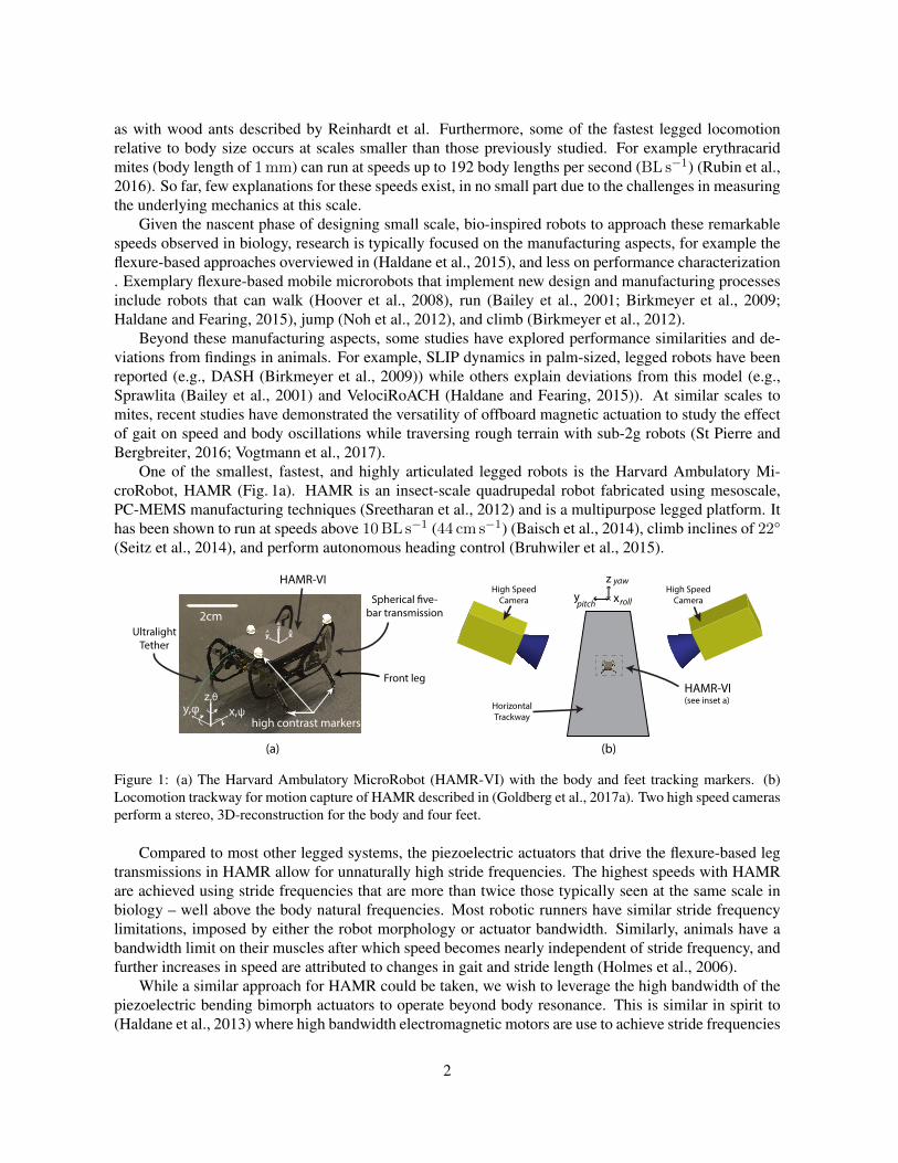
One of the smallest, fastest, and highly articulated legged robots is the Harvard Ambulatory Mi-croRobot, HAMR (Fig. 1a). HAMR is an insect-scale quadrupedal robot fabricated using mesoscale,PC-MEMS manufacturing techniques (Sreetharan et al., 2012) and is a multipurpose legged platform. Ithas been shown to run at speeds above 10BL s−1 (44 cm s−1) (Baisch et al., 2014), climb inclines of 22°(Seitz et al., 2014), and perform autonomous heading control (Bruhwiler et al., 2015).
x
zy rollpitch
yaw
high contrast markers
HAMR-VI
2cmx
zy^
^^
HorizontalTrackway
High SpeedCamera
High SpeedCamera
UltralightTether
Spherical �ve-bar transmission
Front leg
(a) (b)
HAMR-VI(see inset a)
x,ψz,θ
y,φ
Figure 1: (a) The Harvard Ambulatory MicroRobot (HAMR-VI) with the body and feet tracking markers. (b)Locomotion trackway for motion capture of HAMR described in (Goldberg et al., 2017a). Two high speed camerasperform a stereo, 3D-reconstruction for the body and four feet.
Compared to most other legged systems, the piezoelectric actuators that drive the flexure-based legtransmissions in HAMR allow for unnaturally high stride frequencies. The highest speeds with HAMRare achieved using stride frequencies that are more than twice those typically seen at the same scale inbiology – well above the body natural frequencies. Most robotic runners have similar stride frequencylimitations, imposed by either the robot morphology or actuator bandwidth. Similarly, animals have abandwidth limit on their muscles after which speed becomes nearly independent of stride frequency, andfurther increases in speed are attributed to changes in gait and stride length (Holmes et al., 2006).
While a similar approach for HAMR could be taken, we wish to leverage the high bandwidth of thepiezoelectric bending bimorph actuators to operate beyond body resonance. This is similar in spirit to(Haldane et al., 2013) where high bandwidth electromagnetic motors are use to achieve stride frequencies
2
higher than the body dynamics. In contrast to rotary motors where peak torque is produced at stall,piezoelectric actuators have force generation that is independent of actuation frequency up to actuatorresonance (Jafferis et al., 2016a). We wish to leverage this property and operate in frequency regimessuited for different tasks; for example, precision quasi-static motions for orienting a vision system, usingbody resonance to negotiate over obstacles, or exploiting transmission resonance for high speed running.The high bandwidth and power characteristics of piezoelectric actuators allow the potential for all ofthese tasks and this paper addresses the effects of gait selection on performance in low and high frequencyregimes.
In this paper, we describe the control capabilities of HAMR and the methods and metrics used toanalyze its locomotion (Sec. 2). In Section 3, we describe the results of the experimental gait studies.We find that there are distinct differences in body kinematics and dynamics in low and high stride fre-quency regimes (Sec. 3.1) that result in variations in locomotion performance (e.g., speed and cost oftransport (CoT)). At stride frequencies from 50-65Hz, speed is similar across substantial variations ingait (Sec. 3.2). In Sec. 3.3, we discuss the energy and force characteristics of HAMR and show that itfollows a reduced order SLIP model in the body dynamics regime but deviates from this model at highfrequencies (Sec. 3.3). In this regime where stride frequencies surpass the body resonant modes, weobserve “kinematic running” profiles, high speeds, high average step displacement, and low CoT acrosswide variations in gait and without any changes in body morphology. We define “kinematic running” aslocomotion with a Froude number greater than one with horizontal kinetic energy and potential energythat is more similar to a walking template rather than a running template. In Section 3.4, we discusschallenges with achieving high speeds and low CoT by leveraging new metrics of footfall correlationand ineffective stance. A cross-platform analysis (Sec. 3.5) shows that “kinematic running” gaits withHAMR have comparable speeds and CoT compared to other runners at this scale, with speeds upwards of8.5 BL/s, and CoTs lower than 9.4. Finally, we conclude with an outlook on the implications of runningat small scales (Sec. 4) and future work (Sec. 5).
2 Methods
2.1 Platform Overview
HAMR is a 1.43g quadrupedal microrobot with eight degrees of freedom (DOFs) – one lift and one swingDOF per leg (Fig. 2a). The quadrupedal morphology was chosen to reduce manufacturing complexity andoverall size compared to earlier hexapedal HAMR prototypes (Baisch and Wood, 2011), while enablingboth quasi-static and dynamic operation. This design choice was further motivated by rapidly runningcockroaches, which sometimes use quadrupedal or bipedal gaits at high speeds (Full et al., 1991).
The PC-MEMS fabrication process allows for fast and repeatable assembly of HAMR’s complexspherical five-bar (SFB) leg transmissions despite its small scale (Baisch et al., 2014). Each DOF isdriven by a piezoelectric actuator which allows HAMR to run at stride frequencies exceeding 100Hz.Baisch et al. measured speeds on a previous version of HAMR (HAMR-VP) for the trot gait, observinga top speed of 44 cm s−1. In these studies, HAMR was limited to three standard quadrupedal gaits dueto the mechanical coupling between contralateral swing DOFs. The three allowable gaits were the walk,trot, and pace (only the trot, however, was implemented).
Recent design modifications to the powertrain and the addition of two actuators has resulted in twoindependently-actuated DOFs for each leg. These modifications give HAMR-VI a 114% increase in thepayload carrying capacity, larger step displacements, and the potential to achieve aerial phases (Doshiet al., 2015). In addition, with eight independently actuated DOFs, HAMR can now achieve any arbitrarygait including standard quadrupedal gaits such as the jump, bound, and pronk. Example actuator signalsfor a single leg during a 50Hz pronk gait are shown in Fig. 2b with the leg trajectories shown in a
3
0
10 20 30 400
30
60
90
120
150
Inpu
t Vol
tage
(V)
ψSFL
VSFL
VLFL
FL
RL
RR
FR
Time (ms)
(d)
TopView
Front
(b)
Piezoelectric ActuatorsSwing InputLift InputSpherical Five-BarLeg Output
Mechanical Ground
x
y
z
Leg
(a)
swinglift
10 20 30 40
(c)
FLRL
FRRR
LiftSwing
FRRR1cm
directionof motion
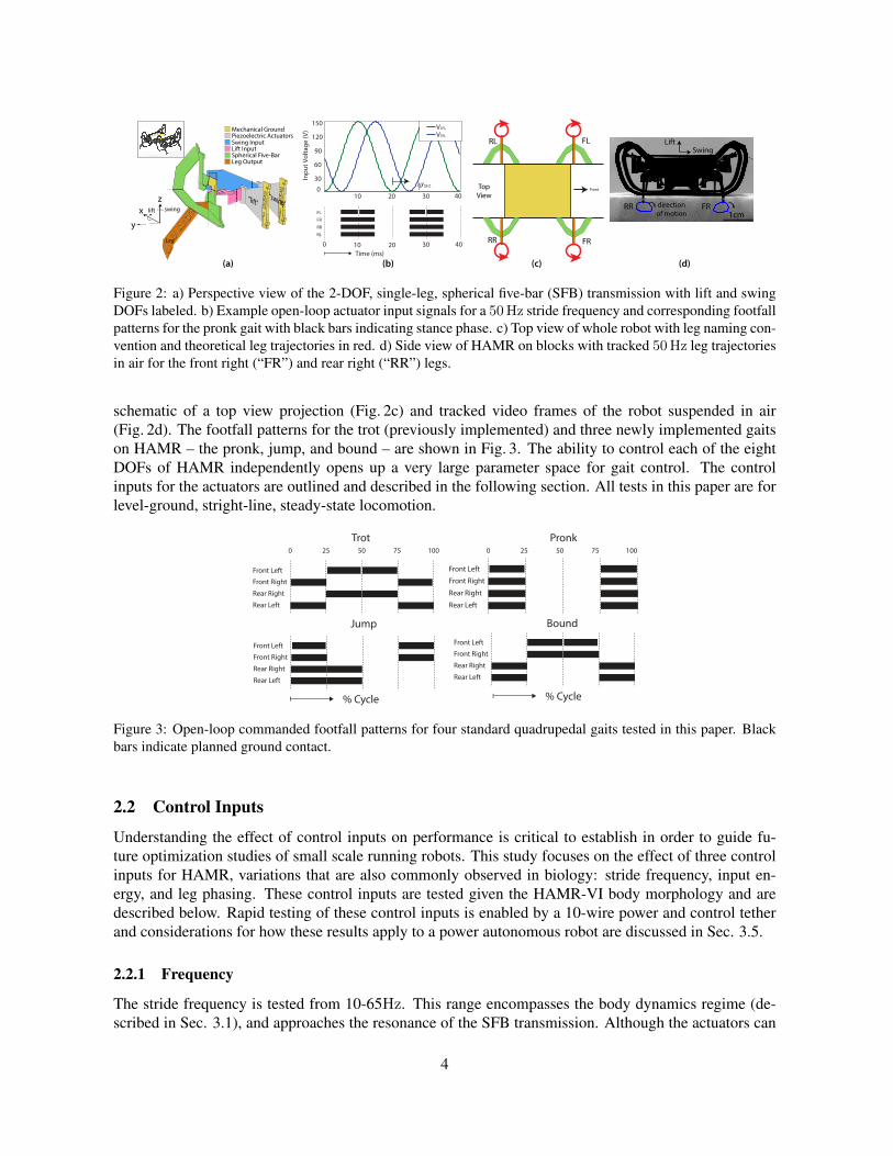
Figure 2: a) Perspective view of the 2-DOF, single-leg, spherical five-bar (SFB) transmission with lift and swingDOFs labeled. b) Example open-loop actuator input signals for a 50Hz stride frequency and corresponding footfallpatterns for the pronk gait with black bars indicating stance phase. c) Top view of whole robot with leg naming con-vention and theoretical leg trajectories in red. d) Side view of HAMR on blocks with tracked 50Hz leg trajectoriesin air for the front right (“FR”) and rear right (“RR”) legs.
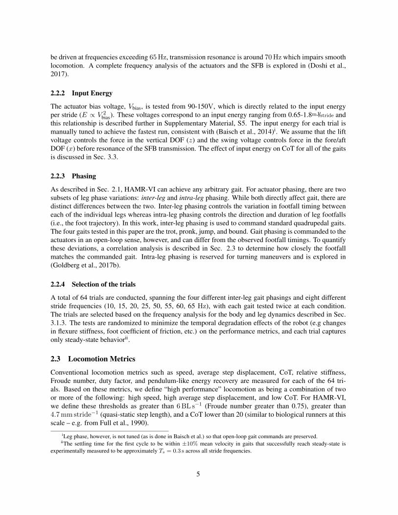
schematic of a top view projection (Fig. 2c) and tracked video frames of the robot suspended in air(Fig. 2d). The footfall patterns for the trot (previously implemented) and three newly implemented gaitson HAMR – the pronk, jump, and bound – are shown in Fig. 3. The ability to control each of the eightDOFs of HAMR independently opens up a very large parameter space for gait control. The controlinputs for the actuators are outlined and described in the following section. All tests in this paper are forlevel-ground, stright-line, steady-state locomotion.
Front Left
Rear Left
Rear Right
Front Right
Jump
Front Left
Rear Left
Rear Right
Front Right
Trot
Front Left
Rear Left
Rear Right
Front Right
Bound
Front Left
Rear Left
Rear Right
Front Right
Pronk
% Cycle
0 10050 7525
% Cycle
0 10050 7525
Figure 3: Open-loop commanded footfall patterns for four standard quadrupedal gaits tested in this paper. Blackbars indicate planned ground contact.
2.2 Control Inputs
Understanding the effect of control inputs on performance is critical to establish in order to guide fu-ture optimization studies of small scale running robots. This study focuses on the effect of three controlinputs for HAMR, variations that are also commonly observed in biology: stride frequency, input en-ergy, and leg phasing. These control inputs are tested given the HAMR-VI body morphology and aredescribed below. Rapid testing of these control inputs is enabled by a 10-wire power and control tetherand considerations for how these results apply to a power autonomous robot are discussed in Sec. 3.5.
2.2.1 Frequency
The stride frequency is tested from 10-65Hz. This range encompasses the body dynamics regime (de-scribed in Sec. 3.1), and approaches the resonance of the SFB transmission. Although the actuators can
4
be driven at frequencies exceeding 65Hz, transmission resonance is around 70Hz which impairs smoothlocomotion. A complete frequency analysis of the actuators and the SFB is explored in (Doshi et al.,2017).
2.2.2 Input Energy
The actuator bias voltage, Vbias, is tested from 90-150V, which is directly related to the input energyper stride (E ∝ V 2
bias). These voltages correspond to an input energy ranging from 0.65-1.8mJ/stride andthis relationship is described further in Supplementary Material, S5. The input energy for each trial ismanually tuned to achieve the fastest run, consistent with (Baisch et al., 2014)i. We assume that the liftvoltage controls the force in the vertical DOF (z) and the swing voltage controls force in the fore/aftDOF (x) before resonance of the SFB transmission. The effect of input energy on CoT for all of the gaitsis discussed in Sec. 3.3.
2.2.3 Phasing
As described in Sec. 2.1, HAMR-VI can achieve any arbitrary gait. For actuator phasing, there are twosubsets of leg phase variations: inter-leg and intra-leg phasing. While both directly affect gait, there aredistinct differences between the two. Inter-leg phasing controls the variation in footfall timing betweeneach of the individual legs whereas intra-leg phasing controls the direction and duration of leg footfalls(i.e., the foot trajectory). In this work, inter-leg phasing is used to command standard quadrupedal gaits.The four gaits tested in this paper are the trot, pronk, jump, and bound. Gait phasing is commanded to theactuators in an open-loop sense, however, and can differ from the observed footfall timings. To quantifythese deviations, a correlation analysis is described in Sec. 2.3 to determine how closely the footfallmatches the commanded gait. Intra-leg phasing is reserved for turning maneuvers and is explored in(Goldberg et al., 2017b).
2.2.4 Selection of the trials
A total of 64 trials are conducted, spanning the four different inter-leg gait phasings and eight differentstride frequencies (10, 15, 20, 25, 50, 55, 60, 65 Hz), with each gait tested twice at each condition.The trials are selected based on the frequency analysis for the body and leg dynamics described in Sec.3.1.3. The tests are randomized to minimize the temporal degradation effects of the robot (e.g changesin flexure stiffness, foot coefficient of friction, etc.) on the performance metrics, and each trial capturesonly steady-state behaviorii.
2.3 Locomotion Metrics
Conventional locomotion metrics such as speed, average step displacement, CoT, relative stiffness,Froude number, duty factor, and pendulum-like energy recovery are measured for each of the 64 tri-als. Based on these metrics, we define “high performance” locomotion as being a combination of twoor more of the following: high speed, high average step displacement, and low CoT. For HAMR-VI,we define these thresholds as greater than 6BL s−1 (Froude number greater than 0.75), greater than4.7mmstride−1 (quasi-static step length), and a CoT lower than 20 (similar to biological runners at thisscale – e.g. from Full et al., 1990).
iLeg phase, however, is not tuned (as is done in Baisch et al.) so that open-loop gait commands are preserved.iiThe settling time for the first cycle to be within ±10% mean velocity in gaits that successfully reach steady-state is
experimentally measured to be approximately Ts = 0.3 s across all stride frequencies.
5
To help further quantify the underlying mechanics of locomotion, two new metrics, ineffective stanceand footfall correlation, are defined in the following sections. The aim for these metrics is to compareand contrast gaits and frequency regimes where body dynamics and foot slippage significantly affectlocomotion. A complete MATLAB structure for all operating conditions and metrics is provided inSupplementary Material, S7.
2.3.1 New metric definitions
Ineffective stance Foot slippage is often observed in animals and robots during locomotion involv-ing perturbations or on complex terrains (Jusufi et al., 2008; Mazouchova et al., 2010; Roberts andKoditschek, 2016). A normalized metric for foot slippage, however, has not yet been established. Priorstudies looking at foot slippage have used metrics such as stride success ratio (Jayaram and Full, 2016)and step displacement (Mazouchova et al., 2013). These metrics work well when the amount of footslippage is binary (foot does or does not slip) or aggregated over all of the legs. However, these measuresdo not quantify slippage as a portion of the stride or capture variations between individual legs.
A new metric, ineffective stance (Is), quantifies the percentage of the gait cycle that is neither “swing”nor “stance”. The gait cycle is considered to consist of three categories: swing, stance, and ineffectivestance. In an ideal gait cycle, the amount of time for swing and stance can be described as the following:
Swing: Amount of time the foot is above the ground (pwz,i > 0) and is swinging forward in abody-fixed frame (vbx,i > 0).
Stance: Amount of time the foot is planted on the ground (pwz,i = 0) and has zero velocity relativeto a fixed world frame (vwx,i = 0).
Ineffective Stance: Amount of time that the leg is slipping on the ground (pwz,i = 0& vwx,i < 0)or swinging backwards in air (pwz,i > 0& vbx,i < 0).
where p and v are the foot positions and velocities in the body (b) or world (w) frames for the x- andz-DOFs of ith foot. Quantitatively, these categories make up the total time, Ttotal, of the cycle(s) of thegait being analyzed:
Ttotal = Tswing + Tstance + Tineffective-stance (1)
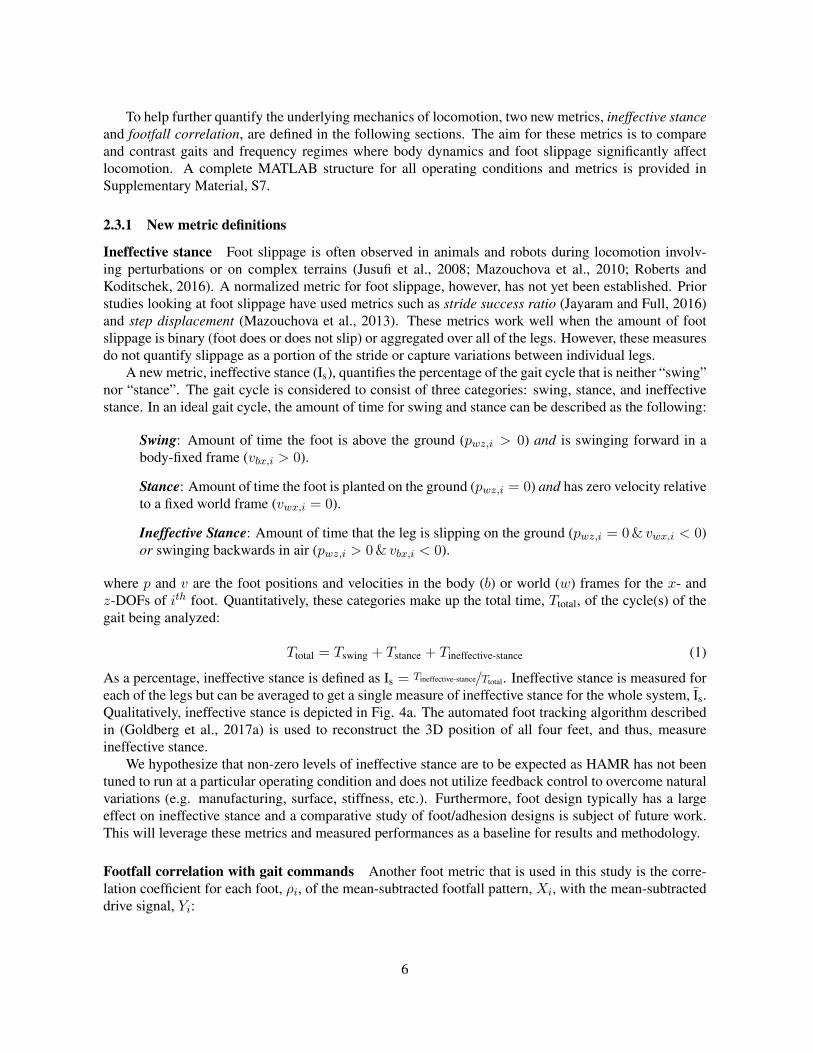
As a percentage, ineffective stance is defined as Is = Tineffective-stance/Ttotal. Ineffective stance is measured foreach of the legs but can be averaged to get a single measure of ineffective stance for the whole system, Is.Qualitatively, ineffective stance is depicted in Fig. 4a. The automated foot tracking algorithm describedin (Goldberg et al., 2017a) is used to reconstruct the 3D position of all four feet, and thus, measureineffective stance.
We hypothesize that non-zero levels of ineffective stance are to be expected as HAMR has not beentuned to run at a particular operating condition and does not utilize feedback control to overcome naturalvariations (e.g. manufacturing, surface, stiffness, etc.). Furthermore, foot design typically has a largeeffect on ineffective stance and a comparative study of foot/adhesion designs is subject of future work.This will leverage these metrics and measured performances as a baseline for results and methodology.
Footfall correlation with gait commands Another foot metric that is used in this study is the corre-lation coefficient for each foot, ρi, of the mean-subtracted footfall pattern, Xi, with the mean-subtracteddrive signal, Yi:
6
pwx(t),pwz(t)
vx,w(t)
x
z
ground
Example of ine�cient leg trajectoryIdeal leg trajectory
red indicates“ine�ective stance”
v=0 t
vx,w
forwardg
vx,b(t) v=0 t
vx,b
ideal stancephase
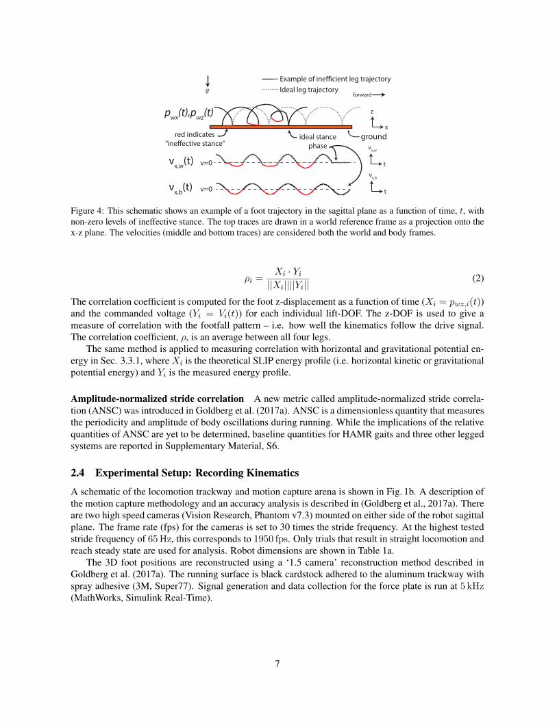
Figure 4: This schematic shows an example of a foot trajectory in the sagittal plane as a function of time, t, withnon-zero levels of ineffective stance. The top traces are drawn in a world reference frame as a projection onto thex-z plane. The velocities (middle and bottom traces) are considered both the world and body frames.
ρi =Xi · Yi||Xi||||Yi||
(2)
The correlation coefficient is computed for the foot z-displacement as a function of time (Xi = pwz,i(t))and the commanded voltage (Yi = Vi(t)) for each individual lift-DOF. The z-DOF is used to give ameasure of correlation with the footfall pattern – i.e. how well the kinematics follow the drive signal.The correlation coefficient, ρ, is an average between all four legs.
The same method is applied to measuring correlation with horizontal and gravitational potential en-ergy in Sec. 3.3.1, where Xi is the theoretical SLIP energy profile (i.e. horizontal kinetic or gravitationalpotential energy) and Yi is the measured energy profile.
Amplitude-normalized stride correlation A new metric called amplitude-normalized stride correla-tion (ANSC) was introduced in Goldberg et al. (2017a). ANSC is a dimensionless quantity that measuresthe periodicity and amplitude of body oscillations during running. While the implications of the relativequantities of ANSC are yet to be determined, baseline quantities for HAMR gaits and three other leggedsystems are reported in Supplementary Material, S6.
2.4 Experimental Setup: Recording Kinematics
A schematic of the locomotion trackway and motion capture arena is shown in Fig. 1b. A description ofthe motion capture methodology and an accuracy analysis is described in (Goldberg et al., 2017a). Thereare two high speed cameras (Vision Research, Phantom v7.3) mounted on either side of the robot sagittalplane. The frame rate (fps) for the cameras is set to 30 times the stride frequency. At the highest testedstride frequency of 65Hz, this corresponds to 1950 fps. Only trials that result in straight locomotion andreach steady state are used for analysis. Robot dimensions are shown in Table 1a.
The 3D foot positions are reconstructed using a ‘1.5 camera’ reconstruction method described inGoldberg et al. (2017a). The running surface is black cardstock adhered to the aluminum trackway withspray adhesive (3M, Super77). Signal generation and data collection for the force plate is run at 5 kHz(MathWorks, Simulink Real-Time).
7
2.5 Robot baseline parameters and performance
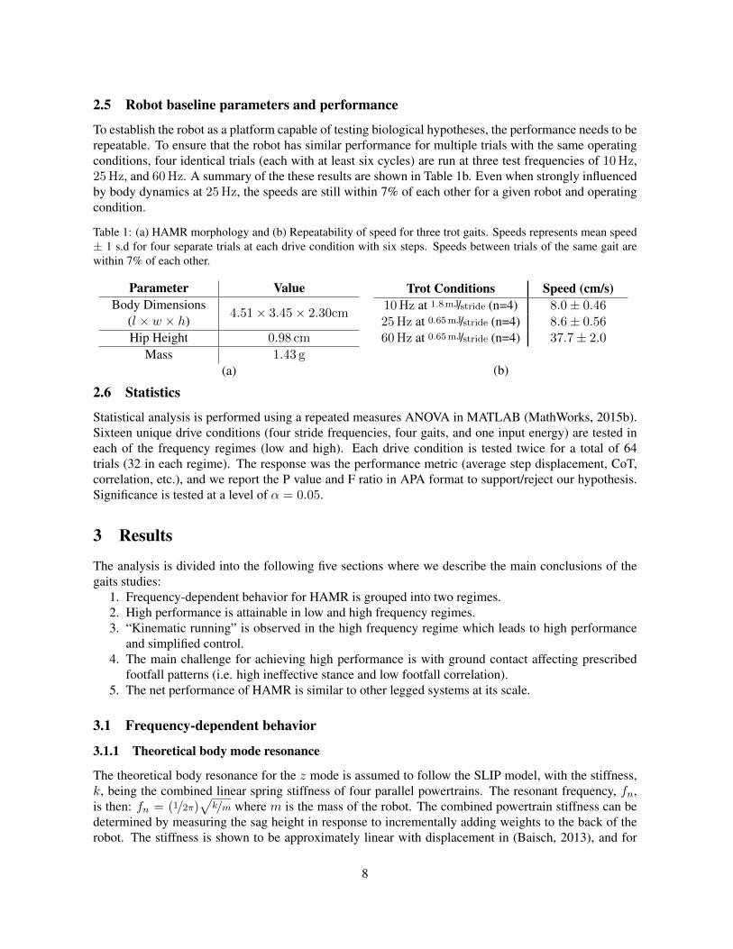
To establish the robot as a platform capable of testing biological hypotheses, the performance needs to berepeatable. To ensure that the robot has similar performance for multiple trials with the same operatingconditions, four identical trials (each with at least six cycles) are run at three test frequencies of 10Hz,25Hz, and 60Hz. A summary of the these results are shown in Table 1b. Even when strongly influencedby body dynamics at 25Hz, the speeds are still within 7% of each other for a given robot and operatingcondition.
Table 1: (a) HAMR morphology and (b) Repeatability of speed for three trot gaits. Speeds represents mean speed± 1 s.d for four separate trials at each drive condition with six steps. Speeds between trials of the same gait arewithin 7% of each other.
Parameter ValueBody Dimensions
(l × w × h)4.51× 3.45× 2.30cm
Hip Height 0.98 cm
Mass 1.43 g(a)
Trot Conditions Speed (cm/s)10Hz at 1.8mJ/stride (n=4) 8.0± 0.4625Hz at 0.65mJ/stride (n=4) 8.6± 0.5660Hz at 0.65mJ/stride (n=4) 37.7± 2.0
(b)
2.6 Statistics
Statistical analysis is performed using a repeated measures ANOVA in MATLAB (MathWorks, 2015b).Sixteen unique drive conditions (four stride frequencies, four gaits, and one input energy) are tested ineach of the frequency regimes (low and high). Each drive condition is tested twice for a total of 64trials (32 in each regime). The response was the performance metric (average step displacement, CoT,correlation, etc.), and we report the P value and F ratio in APA format to support/reject our hypothesis.Significance is tested at a level of α = 0.05.
3 Results
The analysis is divided into the following five sections where we describe the main conclusions of thegaits studies:
1. Frequency-dependent behavior for HAMR is grouped into two regimes.2. High performance is attainable in low and high frequency regimes.3. “Kinematic running” is observed in the high frequency regime which leads to high performance
and simplified control.4. The main challenge for achieving high performance is with ground contact affecting prescribed
footfall patterns (i.e. high ineffective stance and low footfall correlation).5. The net performance of HAMR is similar to other legged systems at its scale.
3.1 Frequency-dependent behavior
3.1.1 Theoretical body mode resonance
The theoretical body resonance for the z mode is assumed to follow the SLIP model, with the stiffness,k, being the combined linear spring stiffness of four parallel powertrains. The resonant frequency, fn,is then: fn = (1/2π)
√k/m where m is the mass of the robot. The combined powertrain stiffness can be
determined by measuring the sag height in response to incrementally adding weights to the back of therobot. The stiffness is shown to be approximately linear with displacement in (Baisch, 2013), and for
8
HAMR-VI, the stiffness is 24Nm−1 which corresponds to a resonant frequency of 20Hz. Due to theinherent nonlinearities of the system (e.g. ground contact and the SFB transmission) and gaits with morethan one instance of ground contact per cycle (all except pronk), the body resonance can be excited withstride frequencies below 20Hz. During the trot, for example, alternating footfalls result in an effectiveexcitation frequency of 20Hz for a 10Hz stride frequency. An experimental characterization of theresonant modes is conducted in the following section.
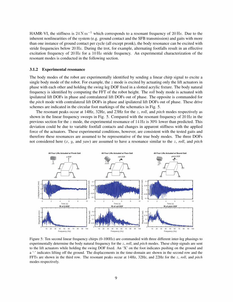
3.1.2 Experimental resonance
The body modes of the robot are experimentally identified by sending a linear chirp signal to excite asingle body mode of the robot. For example, the z mode is excited by actuating only the lift actuators inphase with each other and holding the swing leg DOF fixed in a slotted acrylic fixture. The body naturalfrequency is identified by computing the FFT of the robot height. The roll body mode is actuated withipsilateral lift DOFs in phase and contralateral lift DOFs out of phase. The opposite is commanded forthe pitch mode with contralateral lift DOFs in phase and ipsilateral lift DOFs out of phase. These driveschemes are indicated in the circular foot markings of the schematics in Fig. 5.
The resonant peaks occur at 14Hz, 32Hz, and 23Hz for the z, roll, and pitch modes respectively asshown in the linear frequency sweeps in Fig. 5. Compared with the resonant frequency of 20Hz in theprevious section for the z mode, the experimental resonance of 14Hz is 30% lower than predicted. Thisdeviation could be due to variable footfall contacts and changes in apparent stiffness with the appliedforce of the actuators. These experimental conditions, however, are consistent with the tested gaits andtherefore these resonances are assumed to be representative of the true body modes. The three DOFsnot considered here (x, y, and yaw) are assumed to have a resonance similar to the z, roll, and pitch
0 2 4 6 8 10Time (s)
-2
-1
0
1
z-di
spla
cem
ent (
mm
)
All Four Lifts Actuated w/ Pronk Gait
10 20 30 40 50 60 70 80 90 100Frequency (Hz)
0
1
2
3
4
Mag
nitu
de (m
m)
fft of Z-DOF
0 2 4 6 8 10Time (s)
-0.1
-0.05
0
0.05
0.1
roll-
disp
lace
men
t (ra
d)
All Four Lifts Actuated w/ Pace Gait
10 20 30 40 50 60 70 80 90 100Frequency (Hz)
0
0.05
0.1
0.15
0.2
Mag
nitu
de (r
ad)
fft of roll DOF
0 2 4 6 8 10Time (s)
-0.1
-0.05
0
0.05
0.1
pitc
h-di
spla
cem
ent (
rad)
All Four Lifts Actuated w/ Bound Gait
10 20 30 40 50 60 70 80 90 100Frequency (Hz)
0
0.05
0.1
0.15
0.2
Mag
nitu
de (r
ad)
fft of pitch DOF
z-DOF roll-DOF pitch-DOF
Figure 5: Ten second linear frequency chirps (0-100Hz) are commanded with three different inter-leg phasings toexperimentally determine the body natural frequency for the z, roll, and pitch modes. These chirp signals are sentto the lift actuators while holding the swing DOF fixed. An ‘X’ on the foot indicates pushing on the ground anda ‘·’ indicates lifting off the ground. The displacements in the time-domain are shown in the second row and theFFTs are shown in the third row. The resonant peaks occur at 14Hz, 32Hz, and 22Hz for the z, roll, and pitchmodes respectively.
9
(14-32Hz) since the stiffnesses and inertias have similar values as the tested DOFs (Doshi et al., 2015).Blickhan and Full show that in organisms, running animals over a wide range of sizes and running
speeds have a normalized relative stiffness of approximately 10 (Blickhan and Full, 1993). This indicatesthat the relative individual leg force is roughly ten times greater than the relative compression of thewhole-body leg spring, regardless of animal size and running speeds. Based on the body mode analysisabove, HAMR has a relative stiffness of 4.3 assuming a pronking gait, slightly lower than the trends seenin other legged systems. Relative stiffness, however, can be modulated by altering the input energy, andimplications of this are discussed in Sec. 3.3.
3.1.3 Selection of two frequency regimes
Two distinct frequency regimes are identified to describe the locomotion characteristics of HAMR. One,the low frequency, or “body mode” regime, is considered to be from 10-25Hz. Based on the analysisin 3.1, this is the regime that is most influenced by sagittal plane oscillations (z and pitch). The secondregime, the high frequency regime, is from 50-65Hz. This regime is selected because the analysis in Sec.3.1 shows that sagittal plane oscillations are attenuated above 50Hz.
Prior work with HAMR indicates similar average step displacements in the medium frequency regime(30-45Hz) compared with the high frequency regime before transmission resonance (Baisch et al., 2014;Goldberg et al., 2017a). Therefore, the 30-45Hz stride frequency regime is not tested in order to focuson the regime where highest speed locomotion is achieved, and to highlight the differences between thebody dynamics regime and high speed, high stride frequency regime. Therefore, the 64 trials describedin Sec. 2.2 are grouped into two categories: low and high frequency, with 32 trials in each category.
3.2 Speed and average step displacement characterization
The following sections describe the performance of the gaits in the context of the two regimes: lowfrequency (10-25Hz) and high frequency (50-65Hz).
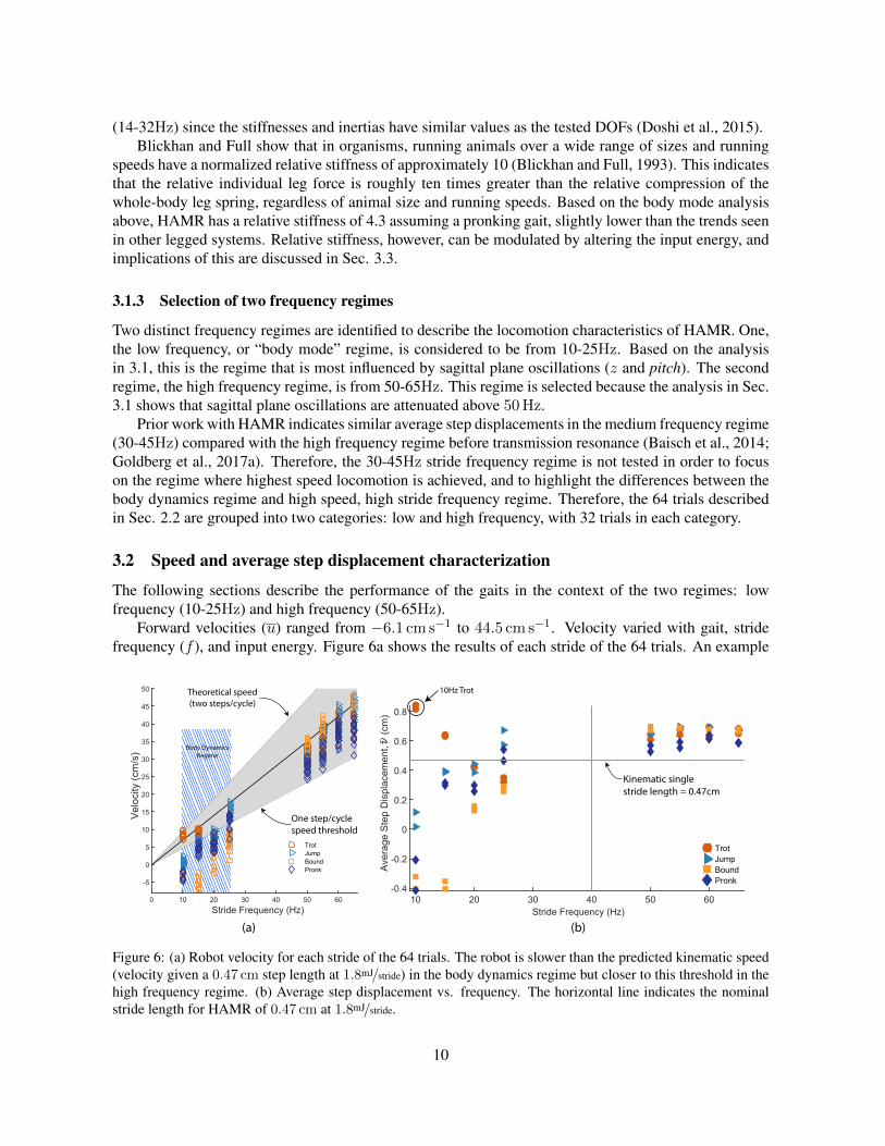
Forward velocities (u) ranged from −6.1 cm s−1 to 44.5 cm s−1. Velocity varied with gait, stridefrequency (f ), and input energy. Figure 6a shows the results of each stride of the 64 trials. An example
Aver
age
Step
Dis
plac
emen
t,
(cm
)
Body DynamicsRegime
Theoretical speed(two steps/cycle)
One step/cyclespeed threshold
(a) (b)
Kinematic single stride length = 0.47cm
10Hz Trot
0 10 20 30 40 50 60Stride Frequency (Hz)
-5
0
5
10
15
20
25
30
35
40
45
50
Velo
city
(cm
/s)
TrotJumpBoundPronk
10 20 30 40 50 60Stride Frequency (Hz)
-0.4
-0.2
0
0.2
0.4
0.6
0.8
TrotJumpBoundPronk
Figure 6: (a) Robot velocity for each stride of the 64 trials. The robot is slower than the predicted kinematic speed(velocity given a 0.47 cm step length at 1.8mJ/stride) in the body dynamics regime but closer to this threshold in thehigh frequency regime. (b) Average step displacement vs. frequency. The horizontal line indicates the nominalstride length for HAMR of 0.47 cm at 1.8mJ/stride.
10
of a tracked trial, the 10Hz trot, is shown in shown electronic supplementary material, video S1, anda qualitative comparison of the four tested gait types at a 60Hz stride frequency is shown in electronicsupplementary material, video S2.
The average step displacement, ν = u/f , is used to compare relative performance of gaits withvarying stride frequencies. One of the gaits that has the highest average step displacement, the 10Hztrot, is in the low frequency regime. It is hypothesized that this is due to constructive influence of bodydynamics on performance. However, some of the lowest performing gaits are also in this regime. Withthese gaits, the direction of travel is unintentionally reversed, most likely due to destructive interferenceof body dynamics. These observations indicate that gaits in the low frequency regime have high variationin average step displacement (0.26±0.35 cm step−1, n=32) due to the influence of body resonant modes.In contrast, gaits in the high frequency regime show much lower variation in average step displacement(0.65 ± 0.04 cm step−1, n=32), despite the same variations in gait as the low stride frequency regime.Comparing the two regimes, there is a significant difference in average step displacement [ANOVA,P < 0.001, F(3,42) = 12.7; Fig. 6b]. Video S3 in the electronic supplementary material shows theprogression of the pronking gait with increasing stride frequency with low (and/or negative) average stepdisplacement in the body dynamics regime and high average step displacement in the high frequencyregime.
3.3 Energy considerations and “kinematic running”
In this section, we describe the energy characteristics of the locomotion patterns of HAMR within thecontext of the SLIP running model and CoT.
3.3.1 SLIP Dynamics
Running in animals (independent of body size, morphology, and number of legs) is typically character-ized by the SLIP running template where the horizontal kinetic energy (HKE) and gravitational potentialenergy (GPE) are in-phase. Additionally, this model has typical ground reaction force patterns where thevertical force (Fz) leads the horizontal force (Fx) by 90 degrees (Blickhan and Full, 1993). In contrast,walking dynamics are characterized by the HKE and GPE being nearly 180 degrees out of phase (Cav-agna et al., 1977). Correlation with these locomotion templates is measured by computing an averagecorrelation coefficient between the template and experimental GPE, HKE, Fz , and Fx.
The running dynamics of HAMR are analyzed by plotting force and energy traces as a function oftimei. An example of one of the best per-stride gaits (high average step displacement) is the trot at 10Hz.Representative force and energy traces for this trial are shown in Fig. 7a. These patterns closely followSLIP dynamics with the HKE and GPE being in-phase and Fz leading Fx by approximately 90 degrees.The correlation with SLIP energy profiles is 0.86. Another gait that closely matches the SLIP profilesis the 15Hz trot (Fig. 7b) with a SLIP energy correlation of 0.72. These two gaits have relatively lowenergy recovery (2.2% and 3.3%, respectively), as is typical of running animals (Cavagna et al., 1977).Asymmetries in the support phase of the trot gaits in Fig. 7 are due to a lack of a tripod of support withthe quadrupedal morphology that causes asymmetric half-strides.
Other gaits (e.g. pronk, jump) with HAMR around this stride frequency, however, do not exhibitenergy profiles that match conventional walking or running templates. These observations are likely dueto footfalls that are not well matched with the body dynamics which ultimately leads to lower speeds.However, video S4 in the electronic supplementary material shows that highly dynamic, open-loop gaitssuch as bipedal running and pronking are possible in the body dynamics regime by finely tuning andexploiting the open-loop instabilities of HAMR. Unfortunately, these gaits are highly sensitive to input
iThe forces are obtained by differentiating the body COM positions.
11

(a) (b)
(c) (d)
F Z (% B
W)
F X (%
BW
)
GPE
(μJ)
HKE
(μJ)25˚
100˚ 75˚
Percent Cycle (%)
Percent Cycle (%)
174˚
124˚
0 20 40 60 80 100134
137.5
141
52
68.5
85
0 20 40 60 80 100
0
100
350
-150
0
170
F (%
BW
)
F (%
BW
)
GPE
(μJ)
HKE
(μJ)
X F Z (% B
W)
F (%
BW
)
GPE
(μJ)
HKE
(μJ)
XPercent Cycle (%)
179˚
75˚
F Z (% B
W)
F X (%
BW
)
GPE
(μJ)
HKE
(μJ)
Percent Cycle (%)
Two examplegaits that resemble
walkingenergy pro�les
25˚
Energy pro�le Approximate theoretical SLIP pro�le
Approximate theoretical ‘walking’ pro�leAerial phase*
*
Two examplegaits that resemble
SLIPenergy pro�les
0 20 40 60 80 100128
139
150
Trot - 10Hz, 150V (2.2% Recovery, 0.86 "SLIP" Correlation)
0
5
10
0 20 40 60 80 1000
100
175
-40
0
40
Pronk - 55Hz, 110V (22.1% Recovery, 0.84 "WALK" Correlation)
0 20 40 60 80 100137.4
137.85
138.3
Trot - 65Hz, 95V (8.8% Recovery, 0.80 "WALK" Correlation)
150
155
160
0 20 40 60 80 1000
100
200
-60
0
60
Z
0 20 40 60 80 100133
136.5
140
Trot - 15Hz, 130V (3.3% Recovery, 0.72 "SLIP" Correlation)
0
6
12
0 20 40 60 80 1000
100
175
-60
0
60
Figure 7: Energy and force traces for the (a) 10Hz trot (n=2 cycles, Fr= 0.07), (b) 15Hz trot (n=4 cycles,Fr= 0.10), (c) 65Hz trot (n=3 cycles, Fr= 2.0), and (d) 55Hz pronk (n=2 cycles, Fr= 1.0). The GPE and HKEfor the SLIP profiles are approximately in-phase in contrast to the gaits that match energy profiles of walking (outof phase). Whole body forces for the SLIP profiles have the z-force leading the x-force by approximately 90°.For gaits that match walking profiles, the x-force leads the z-force by approximately 90°. Percent recovery forgaits that match walking profiles have a higher pendulum-like energy recovery compared to gaits that match SLIPprofiles (8.8% and 22.1% vs. 2.2% and 3.3%). For the 55Hz Pronk, there is an aerial phase for approximately20% of the cycle.
12
variations and in order to make them repeatable, feedback control or design modifications are necessaryfor stabilization.
In contrast to the two SLIP-like gaits, two examples of high frequency gaits are shown in Fig. 7c andd. These gaits have energy profiles that are more similar to pendulum-like walking rather than SLIP-like running. The correlation with pendulum-like energy profiles is 0.80 and 0.84 for the 65Hz Trotand 55Hz Pronk, respectively. Most gaits in the high frequency regime exhibit this type of kinematicrunning behavior where HKE and GPE are nearly out of phase, despite Froude numbers greater than one.Looking more closely at the energy characteristics, the two high frequency gaits show higher energyrecovery (8.8% and 22.1%) compared to 2.2% for the SLIP-like, 10Hz trot in low frequency regime.This higher percent recovery is an indication of walking dynamics (Heglund et al., 1982; Bailey et al.,2001). Table 2 summarizes the speeds achieved with the gaits shown in Fig. 7.
3.3.2 Cost of Transport
Cost of transport is a benchmark measurement of the energy efficiency of a mobile system and is definedas the power cost of moving a unit mass of the system a unit distance. The cost of transport reported inthis paper is a dimensionless measure of the metabolic cost of transport, CoT = P/mgu. Here, P is theaverage input electrical (or metabolic) power, m is the mass, g is the acceleration due to gravity, and uis the average velocity (all in SI units). Cost of transport can be measured on HAMR by measuring theinput electrical power to the piezoelectric actuators. An estimate of the power for HAMR is described inSupplementary Material, S5.
In this paper, voltage was used as a way to tune the input energy. Since the actuators are primarilycapacitive in nature, changing the input electrical energy corresponds to a proportional change in me-chanical energy to the system. Using this input variation, HAMR has the ability to achieve higher forcesand therefore higher foot displacements and velocities given a constant stride frequency. Since we tunedthe input energy to achieve the fastest run for all trials, more efficient locomotion is possible by minimiz-
0 0.1 0.2 0.3 0.4 0.5 0.6 0.7 0.8 0.9Average step displacement, (cm)
0
20
40
60
CoT
TrotJump
BoundPronk
10Hz Trot
10-25Hz50-65 Hz
10Hz Trot
(a)
0 10 20 30 40 50 60Ineffective Stance (%)
-0.5
0
0.5
1
Aver
age
Step
Dis
plac
emen
t, (
cm)
0 10 20 30 40 50 60Ineffective Stance (%)
0
0.2
0.4
0.6
0.8
1
Foot
fall
Cor
rela
tion
with
driv
e si
gnal
, ρ
(c)
(d)
10Hz Trot
0 10 20 30 40 50 60Stride frequency (Hz)
0
20
40
60
(b)
CoT
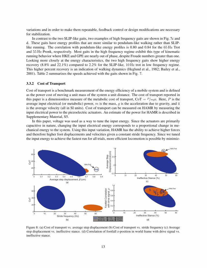
Figure 8: (a) Cost of transport vs. average step displacement (b) Cost of transport vs. stride frequency (c) Averagestep displacement vs. ineffective stance. (d) Correlation of footfall z-position in world frame with drive signal vs.ineffective stance.
13
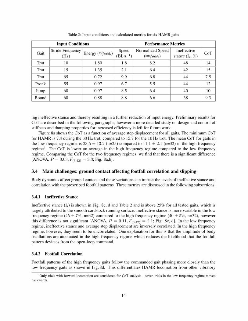
Table 2: Input conditions and calculated metrics for six HAMR gaits
Input Conditions Performance Metrics
GaitStride Frequency
(Hz)Energy (mJ/stride)
Speed(BL s−1)
Normalized Speed(mm/stride)
Ineffectivestance (Is, %)
CoT
Trot 10 1.80 1.8 8.2 48 14
Trot 15 1.35 2.1 6.4 42 15
Trot 65 0.72 9.9 6.8 44 7.5
Pronk 55 0.97 6.7 5.5 44 12
Jump 60 0.97 8.5 6.4 40 10
Bound 60 0.88 8.8 6.6 38 9.3
ing ineffective stance and thereby resulting in a further reduction of input energy. Preliminary results forCoT are described in the following paragraphs, however a more detailed study on design and control ofstiffness and damping properties for increased efficiency is left for future work.
Figure 8a shows the CoT as a function of average step displacement for all gaits. The minimum CoTfor HAMR is 7.4 during the 60Hz trot, compared to 15.7 for the 10Hz trot. The mean CoT for gaits inthe low frequency regime is 23.5 ± 13.2 (n=25) compared to 11.1 ± 2.1 (n=32) in the high frequencyregimei. The CoT is lower on average in the high frequency regime compared to the low frequencyregime. Comparing the CoT for the two frequency regimes, we find that there is a significant difference[ANOVA, P = 0.03, F(3,42) = 3.3; Fig. 8a,b].
3.4 Main challenges: ground contact affecting footfall correlation and slipping
Body dynamics affect ground contact and these variations can impact the levels of ineffective stance andcorrelation with the prescribed footfall patterns. These metrics are discussed in the following subsections.
3.4.1 Ineffective Stance
Ineffective stance (Is) is shown in Fig. 8c, d and Table 2 and is above 25% for all tested gaits, which islargely attributed to the smooth cardstock running surface. Ineffective stance is more variable in the lowfrequency regime (45 ± 7%, n=32) compared to the high frequency regime (40 ± 5%, n=32), howeverthis difference is not significant [ANOVA, P = 0.11, F(3,42) = 2.1; Fig. 8c, d]. In the low frequencyregime, ineffective stance and average step displacement are inversely correlated. In the high frequencyregime, however, they seem to be uncorrelated. One explanation for this is that the amplitude of bodyoscillations are attenuated in the high frequency regime which reduces the likelihood that the footfallpattern deviates from the open-loop command.
3.4.2 Footfall Correlation
Footfall patterns of the high frequency gaits follow the commanded gait phasing more closely than thelow frequency gaits as shown in Fig. 8d. This differentiates HAMR locomotion from other vibratory
iOnly trials with forward locomotion are considered for CoT analysis – seven trials in the low frequency regime movedbackwards.
14
modes (low gait correlation) of locomotion. The correlation of the footfall with the actuator signals is(0.86± 0.03, n=32) in the high frequency regime compared to (0.72± 0.17, n=32) in the low frequencyregime. Figure 8d shows that as footfall deviates from the commanded drive signal (i.e. lower footfallcorrelation with drive signal, ρ), the legs experience higher levels of ineffective stance. This indicates thatthe ineffective stance metric is informative of how well the foot contact follows the commanded footfallpattern. Furthermore, there is a significant difference between the correlation with the drive signal in thetwo frequency regimes [ANOVA, P = 0.04, F(3,42) = 3.0; Fig. 8d]. Two remedies to high ineffectivestance and lower correlation with the drive signals in the body dynamics regime could be changes in thefoot design or feedback control to realize optimized footfall patterns using ground contact sensing.
3.5 Cross-platform comparison
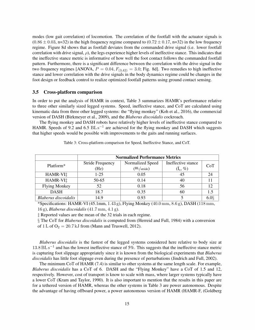
In order to put the analysis of HAMR in context, Table 3 summarizes HAMR’s performance relativeto three other similarly sized legged systems. Speed, ineffective stance, and CoT are calculated usingkinematic data from three other legged systems: the “flying monkey” (Koh et al., 2016), the commercialversion of DASH (Birkmeyer et al., 2009), and the Blaberus discoidalis cockroach.
The flying monkey and DASH robots have relatively higher levels of ineffective stance compared toHAMR. Speeds of 9.2 and 6.5 BL s−1 are achieved for the flying monkey and DASH which suggeststhat higher speeds would be possible with improvements to the gaits and running surfaces.
Table 3: Cross-platform comparison for Speed, Ineffective Stance, and CoT.
Normalized Performance Metrics
Platform*Stride Frequency
(Hz)Normalized Speed
(BL/stride)Ineffective stance
(Is, %)CoT
HAMR-VI‡ 1-25 0.05 45 24HAMR-VI‡ 50-65 0.14 40 11
Flying Monkey 52 0.18 56 12DASH 18.7 0.35 60 1.5
Blaberus discoidalis 14.9 0.93 5 6.0§*Specifications: HAMR-VI (45.1mm, 1.43 g), Flying Monkey (40.0mm, 8.6 g), DASH (118mm,16 g), Blaberus discoidalis (41.7mm, 4.1 g).‡ Reported values are the mean of the 32 trials in each regime.§ The CoT for Blaberus discoidalis is computed from (Herreid and Full, 1984) with a conversionof 1L of O2 = 20.7 kJ from (Mann and Truswell, 2012).
Blaberus discoidalis is the fastest of the legged systems considered here relative to body size at13.8BL s−1 and has the lowest ineffective stance of 5%. This suggests that the ineffective stance metricis capturing foot slippage appropriately since it is known from the biological experiments that Blaberusdiscoidalis has little foot slippage even during the presence of perturbations (Jindrich and Full, 2002).
The minimum CoT of HAMR (7.4) is similar to other systems at the same length scale. For example,Blaberus discoidalis has a CoT of 6. DASH and the “Flying Monkey” have a CoT of 1.5 and 12,respectively. However, cost of transport is know to scale with mass, where larger systems typically havea lower CoT (Kram and Taylor, 1990). It is also important to mention that the results in this paper arefor a tethered version of HAMR, whereas the other systems in Table 3 are power autonomous. Despitethe advantage of having offboard power, a power autonomous version of HAMR (HAMR-F, (Goldberg
15
et al., 2017c)) maintains eight independently actuated DOFs and shows remarkably similar speeds up tostride frequencies of 35Hz (due to microcontroller limitations, the stride frequency is limited to 35Hz),with a top speed of 3.8BL s−1 and a CoT of 85. The main difference in the power autonomous version isin overall mass and power consumption. There is an overhead for high voltage generation that results in apower consumption that is an order of magnitude higher than the tethered version of the robot (480mWvs. 48mW at 15Hz). The high power consumption is primarily due to the overhead in high voltage andcontrol signal generation. The mass of HAMR-F, including a battery, is 2.79 g compared to 1.43 g forHAMR-VI.
4 Conclusion
In this paper, we apply locomotion metrics relevant to small scale locomotion and analyze a large quantityof gaits on HAMR. We analyzed 32 distinct operating conditions spanning stride frequencies from 10-65Hz. More importantly, these frequencies cover two important regimes: one where the stride frequencyis near the body natural frequencies, and one where the stride frequency is more than double the averageof the body natural frequencies.
In the low frequency regime, we find that speed and footfall correlation is highly variable. Despitethese variations, some high performing gaits have energy characteristics similar to SLIP-like running(e.g. the 10 and 15Hz Trots). This suggests that it is possible to fine-tune and control other gaits thatsuffer from destructive body dynamics in this regime. However, without proprioceptive sensing andfeedback control (a challenge at the insect-scale), it is difficult to tune these gaits around body modes fora given body morphology. Additionally, manufacturing and material variations can lead to unpredictabledynamics, making it difficult to stabilize the body dynamics to specific limit-cycles.
In contrast, the open-loop dynamics in the high frequency regime consistently result in high perform-ing gaits. We hypothesize that the simplified lateral and angular control scheme presented in (Goldberget al., 2017b) is possible due to the reduced impact of body dynamics in the high frequency regime. Addi-tionally, we hypothesize that there will be a greater advantage for CoT in the high frequency regime dueto the smaller relative contribution of the overhead cost of onboard, high voltage generation as measuredin Goldberg et al.
Stride frequency and body dynamics are typically constraints for legged runners due to bandwidthlimitations of actuators. In these cases, gait changes such as leg phasing and stride length can be lever-aged to increase speed. In contrast, this paper shows that we are able to utilize the high bandwidth piezo-electric actuators in HAMR to operate in a frequency regime that surpasses the resonant body modesof the robot. In terms of performance, we see that when operating in this regime, different gaits tendto have similar speeds and exhibit kinematic running energy profiles. Furthermore, the footfall patternsof the gaits remain highly correlated with the centralized, feedforward control signals. In other words,footfalls are not stochastic as utilized by some vibration-based, “legged” robots – e.g., HEXBUG andkilobot (Rubenstein et al., 2012).
The trend we report in this paper towards kinematic running at high stride frequencies is consistentwith scaling trends into the micro scale domain – inertial forces become less significant with a decreasein scale, suggesting a shift from dynamic motion to kinematic motion. As we observe in the high fre-quency regime, control strategies for this type of locomotion will likely be different: one hypothesisis that position control (i.e. proprioceptive leg position) will be more important than force control (i.e.controlling SLIP force profiles). A robotic platform such as HAMR can help bridge the gap and exploredifferent running strategies at millimeter scales. Overall, this analysis shows that HAMR is a multipur-pose legged microrobotic platform with the potential for a wide range of applications, including testingbiological hypotheses in neuromechanics, locomotion, and control. Furthermore, the tools, metrics, and
16
methods outlined here are independent of size and can be used across platforms for studying gait inlegged locomotion.
5 Future Work
The experimental analysis presented here is a new methodology for studying gait selection in a leggedrobot with complex dynamics. Hypotheses regarding relative stiffness and body dynamics are easy to teston HAMR. For example, based on the results here, one hypothesis is that a higher leg stiffness might bebeneficial given the high force/high bandwidth piezoelectric actuators. Changes to the relative stiffnesscan alter the frequency where SLIP locomotion naturally occurs (i.e. without force control). This couldoptimize speed and efficiency for a range of applications – for example inspection tasks in confinedspaces or search and rescue for natural disasters or surveillance.
Beyond running straight on flat terrain, this methodology and the new metrics will be applied toother locomotion scenarios such as experiments on perturbation rejection, maneuverability, leg trajectorycontrol, climbing, and locomotion on different surfaces. For example, more stable gaits could resultin higher relative performance on uneven terrain, and lower levels of ineffective stance could improveclimbing capabilities. Such correlations could identify these metrics as valid objectives for designinggaits to accomplish a variety of tasks. The gait analysis can also elucidate the amount of centralizationor sensory feedback needed for future applications requiring high speed and efficient running.
Acknowledgments
The authors thank all members of the Microrobotics Lab for valuable discussions. In particular, wethank Prof. Ardian Jusufi, Prof. Onur Ozcan and Prof. Nick Gravish for helpful discussions on char-acterizing the locomotion of HAMR. Thanks to Prof. Todd Zickler for help developing the locomotionreconstruction analysis during a class project in his Computer Vision class.
Funding
This work is partially funded by the Wyss Institute for Biologically Inspired Engineering and the NationalScience Foundation. This material is based upon work supported by the National Science FoundationGraduate Research Fellowship under Grant Number DGE1144152. Any opinion, findings, and conclu-sions or recommendations expressed in this material are those of the authors and do not necessarily reflectthe views of the National Science Foundation. In addition, the prototypes were enabled by equipmentsupported by the ARO DURIP program (award #W911NF-13-1-0311)
References
Bailey, S. A., Cham, J. G., Cutkosky, M. R., and Full, R. J. (2001). Comparing the locomotion dynamicsof the cockroach and a shape deposition manufactured biomimetic hexapod. In Experimental RoboticsVII, pages 239–248. Springer.
Baisch, A. T. (2013). Design, Manufacturing, and Locomotion Studies of Ambulatory Micro-Robots.PhD thesis, Harvard University School of Engineering and Applied Sciences.
Baisch, A. T., Ozcan, O., Goldberg, B., Ithier, D., and Wood, R. J. (2014). High speed locomotion for aquadrupedal microrobot. The International Journal of Robotics Research, 33(8):1063–1082.
17
Baisch, A. T. and Wood, R. J. (2011). Design and Fabrication of the Harvard Ambulatory Micro-Robot.In Robotics Research, pages 715–730. Springer.
Birkmeyer, P., Gillies, A. G., and Fearing, R. S. (2012). Dynamic climbing of near-vertical smoothsurfaces. In IEEE/RSJ Intl. Conf. on Intelligent Robots and Systems, Vilamoura, Portugal.
Birkmeyer, P., Peterson, K., and Fearing, R. S. (2009). DASH: A dynamic 16g hexapedal robot. InIEEE/RSJ Intl. Conf. on Intelligent Robots and Systems, pages 2683–2689. IEEE.
Blickhan, R. and Full, R. (1993). Similarity in multilegged locomotion: bouncing like a monopode.Journal of Comparative Physiology A, 173(5):509–517.
Bruhwiler, R., Goldberg, B., Doshi, N., Ozcan, O., Jafferis, N., Karpelson, M., and Wood, R. J. (2015).Feedback control of a legged microrobot with on-board sensing. In Intelligent Robots and Systems(IROS), 2015 IEEE/RSJ International Conference on, pages 5727–5733. IEEE.
Cavagna, G. A., Heglund, N. C., and Taylor, C. R. (1977). Mechanical work in terrestrial locomo-tion: two basic mechanisms for minimizing energy expenditure. American Journal of Physiology-Regulatory, Integrative and Comparative Physiology, 233(5):R243–R261.
Chen, J., Peattie, A., Autumn, K., and Full, R. (2006). Differential leg function in a sprawled-posturequadrupedal trotter. Journal of Experimental Biology, 209(2):249–259.
Doshi, N., Goldberg, B., Sahai, R., Jafferis, N., Aukes, D., and Wood, R. J. (2015). Model driven designfor flexure-based microrobots. In Intelligent Robots and Systems (IROS), 2015 IEEE/RSJ InternationalConference on, pages 4119–4126. IEEE.
Doshi, N., Jayaram, K., Goldberg, B., and Wood, R. J. (2017). Phase control for a legged microrobotoperating at resonance. 2017 IEEE International Conference on Robotics and Automation (ICRA).
Full, R., Blickhan, R., and Ting, L. (1991). Leg design in hexapedal runners. Journal of ExperimentalBiology, 158(1):369–390.
Full, R. J. and Koditschek, D. E. (1999). Templates and anchors: neuromechanical hypotheses of leggedlocomotion on land. Journal of Experimental Biology, 202(23):3325–3332.
Full, R. J., Kubow, T., Schmitt, J., Holmes, P., and Koditschek, D. (2002). Quantifying dynamic stabilityand maneuverability in legged locomotion. Integrative and comparative biology, 42(1):149–157.
Full, R. J. and Tu, M. S. (1991). Mechanics of a rapid running insect: two-, four-and six-legged locomo-tion. Journal of Experimental Biology, 156(1):215–231.
Goldberg, B., Doshi, N., and Wood, R. J. (2017a). A high speed motion capture method and performancemetrics for studying gaits on an insect-scale legged robot. Under Review: 2017 IEEE InternationalConference on Robotics and Automation (ICRA).
Goldberg, B., Doshi, N., and Wood, R. J. (2017b). High speed trajectory control using an experimentalmaneuverability model for an insect-scale legged robot. 2017 IEEE International Conference onRobotics and Automation (ICRA).
Goldberg, B., Zufferey, R., Whittredge, G., Doshi, N., Helbling, F. E., Kovac, M., and Wood, R. J.(2017c). Wireless control and power autonomy for a high-speed legged microrobot. Under Review:IEEE/RSJ International Conference on Intelligent Robots and Systems 2017.
18
Haldane, D. W., Casarez, C. S., Karras, J. T., Lee, J., Li, C., Pullin, A. O., Schaler, E. W., Yun, D., Ota,H., and Javey, A. (2015). Integrated manufacture of exoskeletons and sensing structures for foldedmillirobots. Journal of Mechanisms and Robotics, 7(2):021011.
Haldane, D. W. and Fearing, R. S. (2015). Running beyond the bio-inspired regime. In 2015 IEEEInternational Conference on Robotics and Automation (ICRA), pages 4539–4546. IEEE.
Haldane, D. W., Peterson, K. C., Bermudez, F. L. G., and Fearing, R. S. (2013). Animal-inspired designand aerodynamic stabilization of a hexapedal millirobot. In 2013 IEEE International Conference onRobotics and Automation (ICRA), pages 3279–3286. IEEE.
Heglund, N. C., Cavagna, G. A., and Taylor, C. R. (1982). Energetics and mechanics of terrestriallocomotion. iii. energy changes of the centre of mass as a function of speed and body size in birds andmammals. Journal of Experimental Biology, 97(1):41–56.
Herreid, C. F. and Full, R. J. (1984). Cockroaches on a treadmill: aerobic running. Journal of insectphysiology, 30(5):395–403.
Holmes, P., Full, R. J., Koditschek, D., and Guckenheimer, J. (2006). The dynamics of legged locomo-tion: Models, analyses, and challenges. Siam Review, 48(2):207–304.
Hoover, A. M., Steltz, E., and Fearing, R. S. (2008). RoACH: An autonomous 2.4g crawling hexapodrobot. In IEEE/RSJ Intl. Conf. on Intelligent Robots and Systems, pages 22–26.
Jafferis, N. T., Graule, M. A., and Wood, R. J. (2016a). Non-linear resonance modeling and system designimprovements for underactuated flapping-wing vehicles. In 2016 IEEE International Conference onRobotics and Automation (ICRA), pages 3234–3241. IEEE.
Jafferis, N. T., Lok, M., Winey, N., Wei, G.-Y., and Wood, R. J. (2016b). Multilayer laminated piezoelec-tric bending actuators: design and manufacturing for optimum power density and efficiency. SmartMaterials and Structures, 25(5):055033.
Jayaram, K. and Full, R. J. (2016). Cockroaches traverse crevices, crawl rapidly in confined spaces, andinspire a soft, legged robot. Proceedings of the National Academy of Sciences, 113(8):E950–E957.
Jindrich, D. L. and Full, R. J. (2002). Dynamic stabilization of rapid hexapedal locomotion. Journal ofExperimental Biology, 205(18):2803–2823.
Jusufi, A., Goldman, D. I., Revzen, S., and Full, R. J. (2008). Active tails enhance arboreal acrobatics ingeckos. Proceedings of the National Academy of Sciences, 105(11):4215–4219.
Koh, J.-S., Aukes, D. M., Araki, B., Pohorecky, S., Mulgaonkar, Y., Tolley, M. T., Kumar, V., Rus, D.,and Wood, R. J. (2016). A modular folded laminate robot capable of multi modal locomotion. InInternational Symposium on Experimental Robotics (ISER 2016), Tokyo, Japan, Oct., 2016.
Kram, R. and Taylor, C. R. (1990). Energetics of running: a new perspective. Nature, 346(6281):265.
Mann, J. and Truswell, S. (2012). Essentials of human nutrition. Oxford University Press.
Mazouchova, N., Gravish, N., Savu, A., and Goldman, D. I. (2010). Utilization of granular solidificationduring terrestrial locomotion of hatchling sea turtles. Biology letters, 6(3):398–401.
Mazouchova, N., Umbanhowar, P. B., and Goldman, D. I. (2013). Flipper-driven terrestrial locomotionof a sea turtle-inspired robot. Bioinspiration & biomimetics, 8(2):026007.
19
Noh, M., Kim, S.-W., An, S., Koh, J.-S., and Cho, K.-J. (2012). Flea-inspired catapult mechanism forminiature jumping robots. Robotics, IEEE Transactions on, 28(5):1007–1018.
Reinhardt, L., Weihmann, T., and Blickhan, R. (2009). Dynamics and kinematics of ant locomotion: dowood ants climb on level surfaces? The Journal of experimental biology, 212(15):2426–2435.
Roberts, S. F. and Koditschek, D. E. (2016). RHex slips on granular media. In IEEE InternationalConference on Robotics and Automation.
Rubenstein, M., Ahler, C., and Nagpal, R. (2012). Kilobot: A low cost scalable robot system for col-lective behaviors. In 2012 IEEE International Conference on Robotics and Automation (ICRA), pages3293–3298. IEEE.
Rubin, S., Young, M. H.-Y., Wright, J. C., Whitaker, D. L., and Ahn, A. N. (2016). Exceptional runningand turning performance in a mite. Journal of Experimental Biology, 219(5):676–685.
Seitz, B. F., Goldberg, B., Doshi, N., Ozcan, O., Christensen, D. L., Hawkes, E. W., Cutkosky, M. R., andWood, R. J. (2014). Bio-inspired mechanisms for inclined locomotion in a legged insect-scale robot. InRobotics and Biomimetics (ROBIO), 2014 IEEE International Conference on, pages 791–796. IEEE.
Sreetharan, P. S., Whitney, J. P., Strauss, M. D., and Wood, R. J. (2012). Monolithic fabrication ofmillimeter-scale machines. Journal of Micromechanics and Microengineering, 22(5):055027.
St Pierre, R. and Bergbreiter, S. (2016). Gait exploration of sub-2 g robots using magnetic actuation.IEEE Robotics and Automation.
Strogatz, S. H. (2014). Nonlinear dynamics and chaos: with applications to physics, biology, chemistry,and engineering. Westview press.
Ting, L., Blickhan, R., and Full, R. (1994). Dynamic and static stability in hexapedal runners. Journalof Experimental Biology, 197(1):251–269.
Vogtmann, D., Pierre, R. S., and Bergbreiter, S. (2017). A 25 mg magnetically actuated microrobotwalking at> 5 body lengths/sec. In Micro Electro Mechanical Systems (MEMS), 2017 IEEE 30thInternational Conference on, pages 179–182. IEEE.
20