Microrobot Design Using Fiber Reinforced Composites · PDF file1 Microrobot Design Using Fiber...
10
1 Microrobot Design Using Fiber Reinforced Composites R.J. Wood School of Engineering & Applied Sciences Harvard University Cambridge, MA 02138 [email protected] S. Avadhanula, R. Sahai, E. Steltz, R.S. Fearing 1 Dept. of Electrical Engineering & Computer Sciences University of California Berkeley, California 94720 1 [email protected] Abstract— Mobile microrobots with characteristic dimensions on the order of 1cm are difficult to design using either MEMS (microelec- tromechanical systems) technology or precision machining. This is due to the challenges associated with constructing the high strength links and high-speed, low-loss joints with micron scale features required for such systems. Here we present an entirely new framework for creating microrobots which makes novel use of composite materials. This framework includes a new fabrication process termed Smart Composite Microstructures (SCM) for integrating rigid links and large angle flexure joints through a laser micromachining and lamination process. We also present solutions to actuation and integrated wiring issues at this scale using SCM. Along with simple design rules that are customized for this process, our new complete microrobotic framework is a cheaper, quicker, and altogether superior method for creating microrobots that we hope will become the paradigm for robots at this scale. I. I NTRODUCTION All apparatus available for larger scale mechanical systems (mo- tors, revolute joints, bearings, telescopic joints, and robust structural members) become more challenging as size decreases since sur- face effects begin to dominate over Newtonian forces [1]. For this reason, millimeter scale systems based on traditional ‘macro’-scale manufacturing techniques are morphologically limited and articulated structures using revolute or sliding surfaces would be inefficient. Some preliminary MEMS structures have been attempted for micro- robotic mechanisms such as hinge joints [2] and folded structures [3], microrobotic linkages [4], and prototype MEMS microrobots [5], [6]. These devices are constrained by the materials available and MEMS process limitations. Neither end of the manufacturing spectrum offers an acceptable solution for the creation of robust micromechanical systems which can be rapidly prototyped. Further, a holistic fabrication solution is desired; not a concatenation of numerous discrete technologies. We have created a paradigm that incorporates all the mechanical and electromechanical devices that are required for the creation of complete, high performance microrobotic structures. This is some- thing that has not been addressed or attempted elsewhere (either at this scale or with this complexity). Coupled with appropriate mechanical design, this paradigm for creating high performance microstructures is both enabling and holds the potential to eliminate the need for complex control and costly processes. This is based on flexure-jointed (compliant) mechanisms whose links and joints are fabricated in an integrated manner employing a laminate technology that uses high strength composite materials and polymers. This so-called Smart Composite Microstructures (SCM) technology is described in detail in a later section. SCM is a solution to the shortcomings of MEMS and the lim- itations of macro-mechanical machining techniques. This was first introduced in [7] and expanded to include actuator systems in [8], [9]. The resulting structures are truly 3D, unlike the limited 2 1 2 D devices that MEMS processes can create. Not only is this process more versatile than MEMS, it does not require cost-prohibitive infrastructure to implement and the entire process can be performed in a matter of hours (as opposed to months of significant manual labor required for IC processes). Thus the paradigm that we present is an enabling technology for complete integrated microrobots and is simultaneously accessible due to its conceptual simplicity and low infrastructural cost. In this work the SCM fabrication process is detailed for passive and active structures and a model is presented to describe the mechanics of these systems. The focus of the paper is on the production of the complete prototype in an integrated manner, and it provides the necessary procedures for the construction of rigid structural members, links and joints, actuators, electronics and sensors, and wiring. Note that SCM is presented as a fabrication process, not a design flow process. To address microsystem design, this paper also presents simple guidelines for preliminary design of prototype microrobots. These design rules are based on the mechanics of isotropic materials, but we also discuss laminate plate theory as a basis for describing SCM structures. Finally, examples are presented as verification of the SCM process. II. SMART COMPOSITE MICROSTRUCTURE FABRICATION The SCM fabrication process consists of laser micromachining constituent laminae to achieve a desired compliance profile by choice of geometry and material properties. Laser-cutting composite materi- als is not new, but when used to produce thin sheets with micron-scale features for millimeter-scale articulated laminates and actuators, this is a novel fabrication process. For the case of microrobotic structures, links and joints are created when polymers are sandwiched between face sheets of rigid composite materials where gaps in the face sheets create flexures. Actuators are made when any of the laminae are electroactive. Patterned conductive layers bring drive signals to the electroactive elements and allow sensors to be incorporated into the resulting structures. The design and construction of each of these elements is described here as one simple all-inclusive process. A. Composite Process Details Creating a simple flexure joint at this scale presents formidable challenges. Since the resulting static and dynamic parameters rely heavily on geometry, tolerances and alignment are crucial. Also, the creation of rigid links and compliant joints using the morphology shown in Fig. 3 requires either large aspect ratio machining and/or incorporating materials with different elastic properties. Flexure pro- file geometry along with an overview of the solution to creating rigid links and compliant joints is shown in Fig. 1. This solution uses both high aspect ratio, high precision machining, high modulus composite materials (e.g. carbon fiber or S-glass reinforced plastics), and robust thin film polymers. To achieve the structures shown in Fig. 1, a 40μm thick sheet of unidirectional carbon fiber 1 prepreg (Fig. 1(1)) is micromachined by a pulsed laser 2 (Fig. 1(2)). The polymer layer is likewise machined using this laser. The choice of polymer was based upon compatibility 1 M60J from Toray Carbon Fibers America, Inc. 2 either a frequency doubled Nd:Yag laser (λ = 532nm, New Wave Research) or a UV excimer laser (λ = 193nm, TeoSys Engineering)
Transcript of Microrobot Design Using Fiber Reinforced Composites · PDF file1 Microrobot Design Using Fiber...
1
Microrobot Design Using Fiber Reinforced Composites
R.J. WoodSchool of Engineering & Applied Sciences
Harvard UniversityCambridge, MA 02138
S. Avadhanula, R. Sahai, E. Steltz, R.S. Fearing1
Dept. of Electrical Engineering & Computer SciencesUniversity of California
Berkeley, California [email protected]
Abstract— Mobile microrobots with characteristic dimensions on theorder of 1cm are difficult to design using either MEMS (microelec-tromechanical systems) technology or precision machining. This is dueto the challenges associated with constructing the high strength linksand high-speed, low-loss joints with micron scale features requiredfor such systems. Here we present an entirely new framework forcreating microrobots which makes novel use of composite materials. Thisframework includes a new fabrication process termed Smart CompositeMicrostructures (SCM) for integrating rigid links and large angle flexurejoints through a laser micromachining and lamination process. We alsopresent solutions to actuation and integrated wiring issues at this scaleusing SCM. Along with simple design rules that are customized for thisprocess, our new complete microrobotic framework is a cheaper, quicker,and altogether superior method for creating microrobots that we hopewill become the paradigm for robots at this scale.
I. INTRODUCTION
All apparatus available for larger scale mechanical systems (mo-tors, revolute joints, bearings, telescopic joints, and robust structuralmembers) become more challenging as size decreases since sur-face effects begin to dominate over Newtonian forces [1]. For thisreason, millimeter scale systems based on traditional ‘macro’-scalemanufacturing techniques are morphologically limited and articulatedstructures using revolute or sliding surfaces would be inefficient.Some preliminary MEMS structures have been attempted for micro-robotic mechanisms such as hinge joints [2] and folded structures[3], microrobotic linkages [4], and prototype MEMS microrobots[5], [6]. These devices are constrained by the materials availableand MEMS process limitations. Neither end of the manufacturingspectrum offers an acceptable solution for the creation of robustmicromechanical systems which can be rapidly prototyped. Further,a holistic fabrication solution is desired; not a concatenation ofnumerous discrete technologies.
We have created a paradigm that incorporates all the mechanicaland electromechanical devices that are required for the creation ofcomplete, high performance microrobotic structures. This is some-thing that has not been addressed or attempted elsewhere (eitherat this scale or with this complexity). Coupled with appropriatemechanical design, this paradigm for creating high performancemicrostructures is both enabling and holds the potential to eliminatethe need for complex control and costly processes. This is based onflexure-jointed (compliant) mechanisms whose links and joints arefabricated in an integrated manner employing a laminate technologythat uses high strength composite materials and polymers. Thisso-called Smart Composite Microstructures (SCM) technology isdescribed in detail in a later section.
SCM is a solution to the shortcomings of MEMS and the lim-itations of macro-mechanical machining techniques. This was firstintroduced in [7] and expanded to include actuator systems in [8],[9]. The resulting structures are truly 3D, unlike the limited 2 1
2D
devices that MEMS processes can create. Not only is this processmore versatile than MEMS, it does not require cost-prohibitiveinfrastructure to implement and the entire process can be performedin a matter of hours (as opposed to months of significant manual
labor required for IC processes). Thus the paradigm that we presentis an enabling technology for complete integrated microrobots andis simultaneously accessible due to its conceptual simplicity and lowinfrastructural cost.
In this work the SCM fabrication process is detailed for passive andactive structures and a model is presented to describe the mechanicsof these systems. The focus of the paper is on the production ofthe complete prototype in an integrated manner, and it provides thenecessary procedures for the construction of rigid structural members,links and joints, actuators, electronics and sensors, and wiring. Notethat SCM is presented as a fabrication process, not a design flowprocess. To address microsystem design, this paper also presentssimple guidelines for preliminary design of prototype microrobots.These design rules are based on the mechanics of isotropic materials,but we also discuss laminate plate theory as a basis for describingSCM structures. Finally, examples are presented as verification of theSCM process.
II. SMART COMPOSITE MICROSTRUCTURE FABRICATION
The SCM fabrication process consists of laser micromachiningconstituent laminae to achieve a desired compliance profile by choiceof geometry and material properties. Laser-cutting composite materi-als is not new, but when used to produce thin sheets with micron-scalefeatures for millimeter-scale articulated laminates and actuators, thisis a novel fabrication process. For the case of microrobotic structures,links and joints are created when polymers are sandwiched betweenface sheets of rigid composite materials where gaps in the face sheetscreate flexures. Actuators are made when any of the laminae areelectroactive. Patterned conductive layers bring drive signals to theelectroactive elements and allow sensors to be incorporated into theresulting structures. The design and construction of each of theseelements is described here as one simple all-inclusive process.
A. Composite Process Details
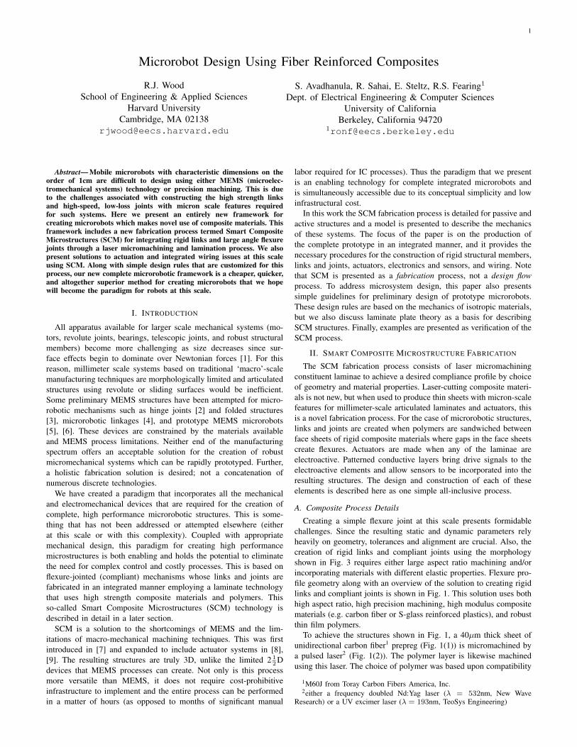
Creating a simple flexure joint at this scale presents formidablechallenges. Since the resulting static and dynamic parameters relyheavily on geometry, tolerances and alignment are crucial. Also, thecreation of rigid links and compliant joints using the morphologyshown in Fig. 3 requires either large aspect ratio machining and/orincorporating materials with different elastic properties. Flexure pro-file geometry along with an overview of the solution to creating rigidlinks and compliant joints is shown in Fig. 1. This solution uses bothhigh aspect ratio, high precision machining, high modulus compositematerials (e.g. carbon fiber or S-glass reinforced plastics), and robustthin film polymers.
To achieve the structures shown in Fig. 1, a 40µm thick sheet ofunidirectional carbon fiber1 prepreg (Fig. 1(1)) is micromachined bya pulsed laser2 (Fig. 1(2)). The polymer layer is likewise machinedusing this laser. The choice of polymer was based upon compatibility
1M60J from Toray Carbon Fibers America, Inc.2either a frequency doubled Nd:Yag laser (λ = 532nm, New Wave
Research) or a UV excimer laser (λ = 193nm, TeoSys Engineering)
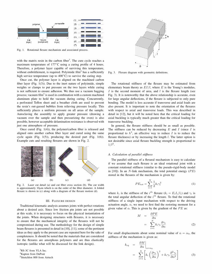
Fig. 1. Rotational flexure mechanism and associated process.
with the matrix resin in the carbon fiber3. The cure cycle reaches amaximum temperature of 177◦C using a curing profile of 4 hours.Therefore, a polymer layer capable of surviving this temperature,without embrittlement, is required. Polyimide film4 has a sufficientlyhigh service temperature (up to 400◦C) to survive the curing step.
Once cut, the polymer layer is aligned on the machined carbonfiber layer (Fig. 1(3)). Due to the inert nature of polyimide, simpleweights or clamps to put pressure on the two layers while curingis not sufficient to ensure adhesion. We thus use a vacuum baggingprocess; vacuum film5 is used in combination with a custom machinedaluminum plate to hold the vacuum during curing. Concurrently,a perforated Teflon sheet and a breather cloth are used to preventthe resin’s out-gassed bubbles from relieving pressure locally. Thissufficiently places a uniform pressure on all areas of the sample.Autoclaving the assembly to apply greater pressure (drawing avacuum over the sample and then pressurizing the oven) is alsopossible, however acceptable delamination resistance is observed withjust one atmosphere of pressure.
Once cured (Fig. 1(4)), the polymer/carbon fiber is released andaligned onto another carbon fiber layer and cured using the samecycle again (Fig. 1(5)), producing the desired part (Fig. 1(6)).Example cuts and resulting flexures are shown in Fig. 2.
(a) (b) (c) (d)
Fig. 2. Laser cut detail (a) and cut fiber cross section (b). The cut widthis approximately 10µm which is on the order of the fiber diameter. A foldedflexure is shown in (c) along with a diagram of the flexure motion (d).
III. FLEXURE DESIGN
Traditional kinematic analysis assumes joints with perfect rotationsabout a desired axis. Since low friction pin joints are not possibleat this scale, it is necessary to focus on the physical instantiation ofthe joints. When designing structures with flexures, it is necessaryto ensure that the mechanical integrity of the flexures will not becompromised during use. The methodology for the design of simplebeam flexures is presented in detail in [10], [11]; some of the pertinentideas as they apply to the present case are repeated here for the sake ofcompleteness. It should be noted that the materials that are consideredfor the flexures are amorphous polymers and are thus elasticallyisotropic (unlike what will be discussed for the link design).
3RS-3C from YLA Inc.4Kapton from DuPont5Stretchlon 800 from Airtech
Fig. 3. Flexure diagram with geometric definitions.
The rotational stiffness of the flexure may be estimated fromelementary beam theory as EI/l, where E is the Young’s modulus,I is the second moment of area, and l is the flexure length (seeFig. 3). It is noteworthy that the above relationship is accurate, evenfor large angular deflections, if the flexure is subjected to only purebending. The model is less accurate if transverse and axial loads arealso present. It is important to note the orientation of the flexureswith respect to axial and transverse loads. This was described indetail in [12], but it will be noted here that the critical loading foraxial buckling is typically much greater than the critical loading fortransverse buckling.
In general, the flexure stiffness should be as small as possible.The stiffness can be reduced by decreasing E and I (since I isproportional to h3, an effective way to reduce I is to reduce theflexure thickness) or by increasing the length l. The latter option isnot desirable since axial flexure buckling strength is proportional to1/l2.
A. Calculation of parallel stiffness
The parallel stiffness of a flexural mechanism is easy to calculateif we assume that each flexure is an ideal rotational joint with aconstant rotational stiffness (similar to the pseudo-rigid-body modelin [10]). In an N -link mechanism, the total potential energy (PE)stored in the flexures of the mechanism is given by:
PEtot =
NXi=1
1
2kiγ
2i (1)
where ki is the stiffness of the ith flexure (ki = EiIi/li) and γi isthe total angular deflection of the ith flexure. To find the rotationalstiffness of a single input mechanism with respect to the drivingactuation angle, α, we need to first find the restoring moment for agiven value of α. This is given by the gradient of the PE as:
M =∂PE
∂α
=
NXi=1
kiγi∂γi
∂α(2)
For small displacements about some nominal value of α = α0, thestiffness of the mechanism is given as:
keq =∂M
∂α
˛α=α0
=
NXi=1
"ki
„∂γi
∂α
«2
+ kiγi∂2γi
∂α2
#(3)
Due to the large change in stiffness with angle for some structures,this expression for keq is only valid for small motions. For thecomplete non-linear dynamics, we should directly use the value ofthe restoring moment M according to (2).
B. Flexure limits
The quantities that should be considered when designing simplebeam flexures include the axial stiffness (Ebh/l), the revolute stiff-ness (Ebh3/12l), and the ratio of axial to revolute stiffness (12/h2).Ideally, the last quantity should be as large as possible. The maximumrotation that a conventional flexure can go through before yielding isalso an important parameter and is given by:
θmax =2lσy
Eh(4)
This last relationship can be easily derived from the formula formaximum bending stresses in a beam subjected to pure bending.Here σy represents the yield stress of the flexure material. As anexample, for a 100µm long polyimide flexure6, θmax ≈ ±40◦. Asstated earlier, an important additional consideration in flexure designis the buckling of the flexure due to axial loads. Modeling the flexureas a link that is fixed at one end and free on the other, the criticalload as determined from the standard Euler buckling relationship isgiven by:
Pcrit =π2EI
4l2(5)
There can be problems associated with flexure mechanisms thatdon’t occur with rotary joints such as undesired off-axis com-pliance and a non-stationary axis of rotation. These issues havebeen addressed with novel mechanisms such as split-tube flexures[11], redundant parallel compliant members [13], [14], and isolationand inversion mechanisms [15], and some of these concepts areappropriate for use with the SCM process. Off-axis compliance isa major concern since any undesired compliances within a serialtransmission chain (for example, a desired rotation that is insteada combination of a rotation and flexure buckling) can exacerbatenonlinearities and backlash. Also, axis drift, if sufficiently severe canlead to undesired kinematic singularities or over-constrained parallelmechanisms.
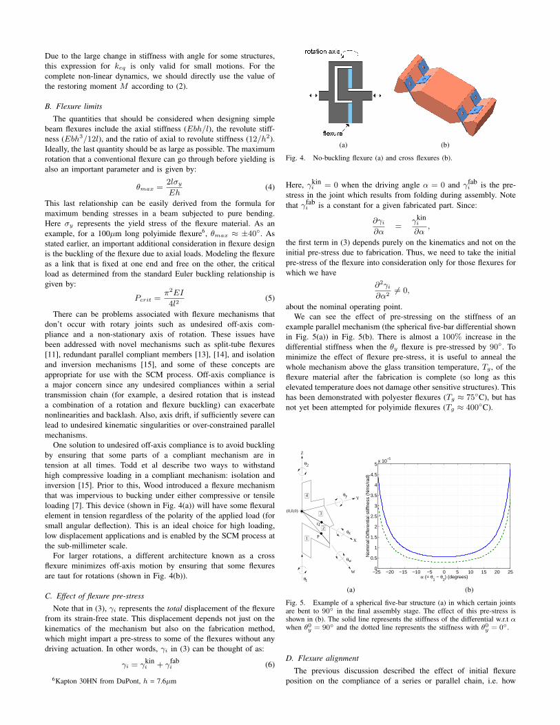
One solution to undesired off-axis compliance is to avoid bucklingby ensuring that some parts of a compliant mechanism are intension at all times. Todd et al describe two ways to withstandhigh compressive loading in a compliant mechanism: isolation andinversion [15]. Prior to this, Wood introduced a flexure mechanismthat was impervious to bucking under either compressive or tensileloading [7]. This device (shown in Fig. 4(a)) will have some flexuralelement in tension regardless of the polarity of the applied load (forsmall angular deflection). This is an ideal choice for high loading,low displacement applications and is enabled by the SCM process atthe sub-millimeter scale.
For larger rotations, a different architecture known as a crossflexure minimizes off-axis motion by ensuring that some flexuresare taut for rotations (shown in Fig. 4(b)).
C. Effect of flexure pre-stress
Note that in (3), γi represents the total displacement of the flexurefrom its strain-free state. This displacement depends not just on thekinematics of the mechanism but also on the fabrication method,which might impart a pre-stress to some of the flexures without anydriving actuation. In other words, γi in (3) can be thought of as:
γi = γkini + γfab
i (6)
6Kapton 30HN from DuPont, h = 7.6µm
(a) (b)
Fig. 4. No-buckling flexure (a) and cross flexures (b).
Here, γkini = 0 when the driving angle α = 0 and γfab
i is the pre-stress in the joint which results from folding during assembly. Notethat γfab
i is a constant for a given fabricated part. Since:
∂γi
∂α=
γkini
∂α,
the first term in (3) depends purely on the kinematics and not on theinitial pre-stress due to fabrication. Thus, we need to take the initialpre-stress of the flexure into consideration only for those flexures forwhich we have
∂2γi
∂α26= 0,
about the nominal operating point.We can see the effect of pre-stressing on the stiffness of an
example parallel mechanism (the spherical five-bar differential shownin Fig. 5(a)) in Fig. 5(b). There is almost a 100% increase in thedifferential stiffness when the θy flexure is pre-stressed by 90◦. Tominimize the effect of flexure pre-stress, it is useful to anneal thewhole mechanism above the glass transition temperature, Tg , of theflexure material after the fabrication is complete (so long as thiselevated temperature does not damage other sensitive structures). Thishas been demonstrated with polyester flexures (Tg ≈ 75◦C), but hasnot yet been attempted for polyimide flexures (Tg ≈ 400◦C).
Q
θy
θx
θw
θ2
θ1
Z
Y
X
4
2
1
3
W
(0,0,0)
P
−25 −20 −15 −10 −5 0 5 10 15 20 250
0.5
1
1.5
2
2.5
3
3.5
4
4.5
5x 10
−5
α (= θ1 − θ
2) (degrees)
Nom
inal
Diff
eren
tial s
tiffn
ess
(Nm
s/ra
d)
(a) (b)
Fig. 5. Example of a spherical five-bar structure (a) in which certain jointsare bent to 90◦ in the final assembly stage. The effect of this pre-stress isshown in (b). The solid line represents the stiffness of the differential w.r.t αwhen θ0
y = 90◦ and the dotted line represents the stiffness with θ0y = 0◦.
D. Flexure alignment
The previous discussion described the effect of initial flexureposition on the compliance of a series or parallel chain, i.e. how
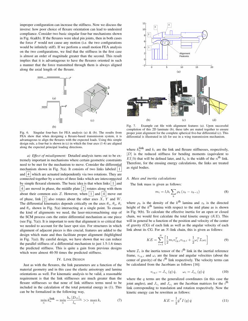
improper configuration can increase the stiffness. Now we discuss theinverse: how poor choice of flexure orientation can lead to undesiredcompliance. Consider two basic singular four-bar mechanisms shownin Fig. 6(a&b). If the flexures were ideal pin joints, then in both casesthe force F would not cause any motion (i.e. the two configurationswould be infinitely stiff). If we perform a small motion FEA analysison the two configurations, we find that the stiffness in the first caseis almost an order of magnitude greater than the second. This resultimplies that it is advantageous to have the flexures oriented in sucha manner that the force transmitted through them is always alignedalong the axial length of the flexure.
(a)
(b)
(c)
Fig. 6. Singular four-bars for FEA analysis (a) & (b). The results fromFEA show that when designing a flexure-based transmission system, it isadvantageous to align the flexures with the expected loads. Using this simpledesign rule, a four-bar is shown in (c) in which the four axes (1-4) are alignedalong the expected principal loading directions.
a) Effect of misalignment: Detailed analysis turns out to be ex-tremely important in mechanisms where certain geometric constraintsneed to be met for the mechanism to move. Consider the differentialmechanism shown in Fig. 5(a). It consists of two links labeled 1and 4 which are actuated independently via two rotations. They areconnected together by a series of three links which are interconnectedby simple flexural elements. The basic idea is that when links 1 and4 are moved in phase, the middle plate 2 rotates along with them
about their common axis Z. However, when 1 and 4 move outof phase, link 2 also rotates about the other axes X , Y and W .The differential kinematics depends critically on the axes θx, θy , θz
and θw shown in Fig. 5(a) intersecting at a single point. To ensurethe kind of alignments we need, the laser-micromachining step ofthe SCM process cuts the entire differential mechanism as one piece(see Fig. 7(a)). It is important to note that alignment is so critical thatwe needed to account for the laser spot size. For structures in whichalignment of adjacent pieces is this crucial, features are added to thedesign which mate and thus facilitate proper alignment (highlightedin Fig. 7(a)). By careful design, we have shown that we can reducethe parallel stiffness of a differential mechanism to just 1.5-1.6 timesthe predicted stiffness. This is quite a gain from previous designswhich were almost 40-50 times the predicted stiffness.
IV. LINK DESIGN
Just as with the flexures, the link parameters are a function of thematerial geometry and in this case the elastic anisotropy and laminaorientations as well. For kinematic analysis to be valid, a reasonablerequirement is that the link stiffnesses are much greater than theflexure stiffnesses so that none of link stiffness terms need to beincluded in the calculation of the total potential energy in (1). Thiscan be be formalized in the following way,
minn
klinkn = min
n
bn [D11]nln
>> maxi
ki (7)
0 5 10 15 20−2
0
2
4
6
8
10
12
AlignmentFeatures
1
2
34
(a)
(b) (c) (d)
Fig. 7. Example cut file with alignment features (a). Upon successfulcompletion of this 2D laminate (b), these tabs are mated together to ensureproper joint alignment for the complete spherical five-bar differential (c). Thisdifferential is illustrated in (d) for use in a wing transmission mechanism.
where klinkn and ki are the link and flexure stiffnesses, respectively,
[D] is the reduced stiffness for bending moments (equivalent toEI/b) that will be defined later, and bn is the width of the nth link.Therefore, for the ensuing energy calculations, the links are treatedas rigid bodies.
A. Mass and inertia calculations
The link mass is given as follows:
mi = libi
Xk
ρk (zk − zk−1) (8)
where ρk is the density of the kth lamina and zk is the directedheight of the kth lamina with respect to the mid plane as is shownin Fig. 9(b). To calculate the effective inertia for an open or closedchain, we would first calculate the total kinetic energy (KE). Thiswill in general be a function of the position and velocity of the centerof gravity (CG) of each link as well as the angular velocity of eachlink about its CG. For an N -link chain, this is given as follows:
KE =
NXi=1
»1
2miv
Tcg,ivcg,i +
1
2ωT
i Iiωi
–(9)
where Ii is the inertia tensor of the ith link in the inertial referenceframe, vcg,i and ωi are the linear and angular velocities (about thecenter of gravity) of the ith link respectively. The velocity terms canbe calculated from the Jacobians as follows [16]:
vcg,i = Jvi (q) q, ωi = Jωi (q) q (10)
where the q terms are the generalized coordinates (in this case thejoint angles), and Jvi and Jωi are the Jacobian matrices for the ith
link corresponding to translation and rotation respectively. Now thekinetic energy can be rewritten as follows:
KE =1
2qT I (q) q (11)
where I (q) is the system’s inertia matrix,
I (q) =
"NX
i=1
“miJvi (q)T Jvi (q) + Jωi (q)T IiJωi (q)
”#(12)
The derivation of the Jacobian is historically well established andoutside the scope of this paper, however, as an example, consider aclosed-chain single input, single output system (a four-bar linkage)as is shown in Fig. 8(a). The generalized coordinate for this system isthe joint angle α with the ‘output’ for this system being the angle β.Thus for L1 > L3, this system amplifies angular motions as is shownin Fig. 8(b). Analytically solving for the kinematics and Jacobianis cumbersome, however, numerical simulation using equ. (12) caneasily give the inertia properties for the four-bar as a function of theinput and the link mass from equ. (8).
(a)
−10 −5 0 5 10−100
−50
0
50
100
β (°
)
l2=l
1, l
1=5l
3
−10 −5 0 5 101
1.5
2
2.5
iner
tia
α (°)
(b)
Fig. 8. Closed-chain four-bar schematic (a) and typical input-outputcharacteristics and normalized inertia (b).
B. Laminate plate theory
Since each structural element created with SCM is a laminatedbeam comprised of flat plates, and each plate is assumed to have athickness much less than either its width or length, a plane stress statecan be assumed in which z-axis stresses are ignored. This allows usto analyze the system using a reduced tensor notation called laminateplate theory. This gives versatility to analytical or numerical analysisof such systems and includes all deformations of a beam in responseto internal or external forces and moments. To begin the analysis,individual ply stresses and strains are defined as follows:24 σx
σy
τxy
35k
=
24 Q11 Q12 Q16
Q12 Q22 Q26
Q16 Q26 Q66
35k
24 εx
εy
γxy
35k
(13)
Where [Qij ]k is the adjusted stiffness matrix whose elements havethe following properties:ˆ
Qij
˜k
= [T ]−1k [Qij ]k [T ]−T
k (14)
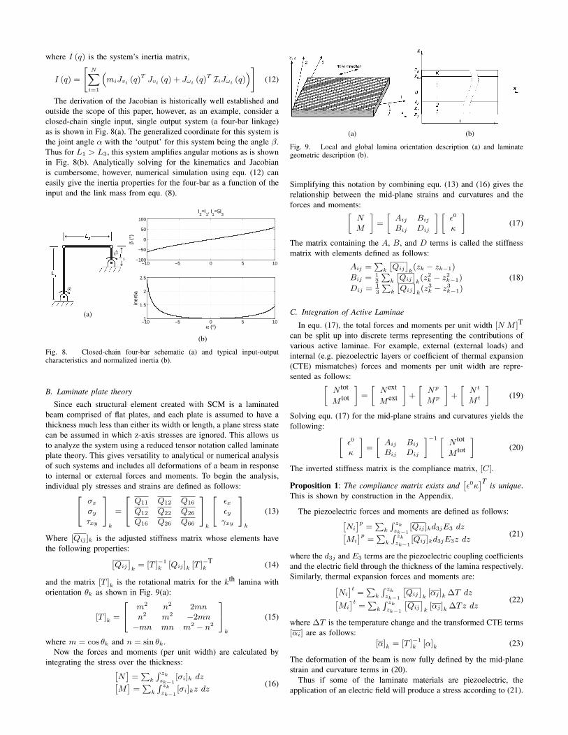
and the matrix [T ]k is the rotational matrix for the kth lamina withorientation θk as shown in Fig. 9(a):
[T ]k =
24 m2 n2 2mnn2 m2 −2mn−mn mn m2 − n2
35k
(15)
where m = cos θk and n = sin θk.Now the forces and moments (per unit width) are calculated by
integrating the stress over the thickness:ˆN
˜=
Pk
R zk
zk−1[σi]k dzˆ
M˜
=P
k
R zk
zk−1[σi]kz dz
(16)
(a) (b)
Fig. 9. Local and global lamina orientation description (a) and laminategeometric description (b).
Simplifying this notation by combining equ. (13) and (16) gives therelationship between the mid-plane strains and curvatures and theforces and moments:»
NM
–=
»Aij Bij
Bij Dij
– »ε0
κ
–(17)
The matrix containing the A, B, and D terms is called the stiffnessmatrix with elements defined as follows:
Aij =P
k
ˆQij
˜k(zk − zk−1)
Bij = 12
Pk
ˆQij
˜k(z2
k − z2k−1)
Dij = 13
Pk
ˆQij
˜k(z3
k − z3k−1)
(18)
C. Integration of Active Laminae
In equ. (17), the total forces and moments per unit width [N M ]T
can be split up into discrete terms representing the contributions ofvarious active laminae. For example, external (external loads) andinternal (e.g. piezoelectric layers or coefficient of thermal expansion(CTE) mismatches) forces and moments per unit width are repre-sented as follows:»
N tot
M tot
–=
»Next
Mext
–+
»Np
Mp
–+
»N t
M t
–(19)
Solving equ. (17) for the mid-plane strains and curvatures yields thefollowing: »
ε0
κ
–=
»Aij Bij
Bij Dij
–−1 »N tot
M tot
–(20)
The inverted stiffness matrix is the compliance matrix, [C].
Proposition 1: The compliance matrix exists andˆε0κ
˜T is unique.This is shown by construction in the Appendix.
The piezoelectric forces and moments are defined as follows:ˆNi
˜p=
Pk
R zk
zk−1[Qij ]kd3jE3 dzˆ
Mi
˜p=
Pk
R zk
zk−1[Qij ]kd3jE3z dz
(21)
where the d3j and E3 terms are the piezoelectric coupling coefficientsand the electric field through the thickness of the lamina respectively.Similarly, thermal expansion forces and moments are:ˆ
Ni
˜t=
Pk
R zk
zk−1
ˆQij
˜k[αj ]k ∆T dzˆ
Mi
˜t=
Pk
R zk
zk−1
ˆQij
˜k[αj ]k ∆Tz dz
(22)
where ∆T is the temperature change and the transformed CTE terms[αi] are as follows:
[α]k = [T ]−1k [α]k (23)
The deformation of the beam is now fully defined by the mid-planestrain and curvature terms in (20).
Thus if some of the laminate materials are piezoelectric, theapplication of an electric field will produce a stress according to (21).

Similarly, if there is a mismatch between lamina CTEs, thermal forcesand moments are obtained by adjusting the laminate temperature.These are two specific examples, however lamina with other modes ofactuation are also encompassed within the model such as: shape mem-ory alloys, electrostrictive materials, electroactive polymers, magne-tostrictive materials, etc. Any material which changes its geometry (ina simple manner) in response to an applied excitation (magnetic field,electric field, current, temperature change, etc) can be used so long asit is a thin lamina. As a caveat to this, the active lamina need not beamorphous. For example, bundles of piezoelectric fibers would notbe modeled using this method. However, binding these fibers withina matrix and creating a thin piezoelectric composite lamina, thenassuming the beam is amorphous (with properties estimated from arule of mixtures) is also encompassed7.
For many of the materials mentioned, force transduction can beinvertible. Some of the same materials that can be used to createactuators can also be used to sense loads applied to the structure.
D. Integration of Compliant Conductors
For the majority of transducers considered here, electric signalsneed to be brought to or from the links. Since all the cases heredescribe systems which have meticulously designed dynamic proper-ties, stringing discrete wires in parallel with the flexures is out of thequestion, particularly when crossing joints undergoing large angularmotions. Proximal actuation is a key benefit to parallel mechanisms.However, distally located sensors and/or actuators are often necessaryor highly desirable and thus the problem of electrical connections overjoints needs to be addressed.
There are two considerations to address for this problem. First,the wiring across the joint must remain intact over a large rangeof motion yet not interfere with the operation of the joint. Second,the wiring needs to facilitate electrical connections to the rest ofthe structure in an easy and reliable manner. Ideally, we wouldlike the wiring to be directly integrated into the flexure joint.However, directly printed wires on the joint are prone to crackingand potentially add undesirable stiffness. With this in mind, we choseto keep the wiring as a separate ribbon structure looped over thejoint (see Fig. 10). Although this wiring will form a large loop,its mechanical parameters can be calculated by using beam flexureformulas discussed previously (since the thickness of the ribbon isvery small compared to the radius of the loop [17]). Also, because theribbon cable wiring is parallel to the flexure joint, the total stiffnessof the joint is the sum of the stiffnesses of the ribbon and the flexure.Given the material properties of the wiring, this ribbon loop can bedesigned to have negligible impact on the stiffness of the joint.
For the material of the wiring, we chose a metal foil (either copperor gold, ≈ 5µm thick) with emphasis on integrity and reliability. Thefoil is patterned into discrete wires (400µm wide wires with 150µmspacing) using the SCM process. An adhesion promoter is then spin-coated onto the patterned foil, and polyimide8 is spin-coated on top ofthe foil (to be used as an adhesion layer). To form a suitable substrate,polyimide (Kapton) is soft-baked on a hot plate at approximately100◦C for 10-20 minutes. The wire ribbon (patterned foil and Kaptonsubstrate) is then released and hard baked separately for an additional20 to 30 minutes at over 300◦C to remove any remaining solvents.This ribbon can now be laser micromachined and used as any otherlayer in the SCM process.
To facilitate electrical interconnections, the ends of these wires aretinned with a low melting point solder. Two wires can be connected
7this is exactly analogous to the assumptions made for fiber-reinforcedcomposite materials in general
8PI2525 or PI2611 from HD Microsystems
(a) (b)
(c)
Fig. 10. Components and assembly method to integrate wiring over theflexure joints (a). In (b), a complete ribbon cable is integrated with a four-bar mechanism (illustrated in (c)) and actuated through a large displacement(≈ 90◦) as a proof-of-concept.
together by layering the solder-coated sides together and a quickapplication of heat. (Again, see Fig. 10(a)).
It should be noted that other materials, such as conductive poly-mers, could also be implemented as a wiring material as long asthe wiring loop across the joint is of sufficient length to keep theconductors intact and the stiffness of the loop low (i.e., << than thestiffness of the joint).
V. RESULTS
A. Articulated microstructures
The paradigm that has been described here gives the user thecapability to create a broad array of articulated structures. Examplesinclude a slider-crank, four-bar, five-bar, and Sarrus linkage. Theseare only a small subset of the devices that can be constructed. Theonly limitation of the SCM process is revolute joints; any articulatedstructure can be created using this process so long as the joints rotatethrough less than 2π (although ±π/3 is a more practical limit). As afirst example of a complex articulated microstructure, Fig. 11 showsa transmission system consisting of two slider-cranks, two parallelfour-bars, and a spherical five-bar differential. The five-bar portionof the structure in Fig. 11 is displayed in greater detail in Fig. 5 andFig. 7 and a four-bar design is illustrated in Fig. 6(c) and Fig. 8(a).
In some cases it is desirable to couple linear motion. In such cases,a Sarrus linkage can be used [18]. This is an additional microstructureenabled by this process and is illustrated in Fig. 12.
B. SCM actuators
As was described in sec. IV-C, incorporating electroactive laminaecan produce induced-strain actuators. Using the analysis presentedearlier, a geometric configuration was determined for optimal powertransduction for a target microrobotic structure (in this case, thewing transmission of a flying robotic insect). The actuators depictedin Fig. 13 are 10mm long, have up to ±250µm displacement, canprovide ±50mN of force, and weigh ≈10mg each [9]. At an operating
(a)
(b)
Fig. 11. Example 2DOF transmission system containing 15 joints (a). Thisis shown along side a SCM instantiation (b).
Fig. 12. Sarrus linkage used as a linear translational bearing.
frequency of 200Hz (quasi-static), these actuators can produce powerdensities >300Wkg−1 which is comparable to high performance DCmotors.
Fig. 13. Composite bimorph PZT-based actuators to be used as clamped-freebending cantilevers.
C. Rigid Microstructures
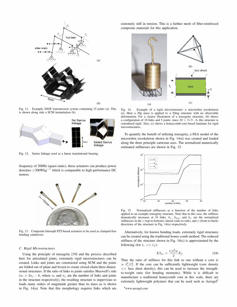
Using the principle of tensegrity [19] and the process describedhere for articulated joints, extremely rigid microstructures can becreated. Links and joints are constructed using SCM and the jointsare folded out of plane and frozen to create closed-chain three dimen-sional structures. If the ratio of links to joints satisfies Maxwell’s rule(nl > 3nj − 6, where nl and nj are the number of links and jointsin the structure respectively), the resulting structure is impervious toloads many orders of magnitude greater than its mass as is shownin Fig. 14(a). Note that this morphology requires links which are
extremely stiff in tension. This is a further merit of fiber-reinforcedcomposite materials for this application.
(a)
(b)
(c)
Fig. 14. Example of a rigid microstructure: a microrobot exoskeleton(a). Here a 20g mass is applied to a 20mg structure with no observabledeformation. For a clearer illustration of a tensegrity structure, (b) showsa configuration of 10 links and 5 joints: since 10 > 3×5 - 6, this structure isconsidered rigid. Also, (c) shows a honeycomb-core-based laminate for rigidmicrostructures.
To quantify the benefit of utilizing tensegrity, a FEA model of themicrorobot exoskeleton shown in Fig. 14(a) was created and loadedalong the three principle cartesian axes. The normalized numericallyestimated stiffnesses are shown in Fig. 15.
20 25 30 35 4010
−3
10−2
10−1
100
norm
aliz
ed s
tiffn
ess
number of links
kz
klat
kx
Fig. 15. Normalized stiffnesses as a function of the number of linksapplied to an example tensegrity structure. Note that in this case, the stiffnessdramatically increases at 34 links. kz , klat, and kx are the normalizedstiffnesses in the z (top-to-bottom), lateral (side-to-side), and x (front-to-back)directions of the structure in Fig. 14(a) respectively.
Alternatively, for known bending loads, extremely rigid structurescan be created using the traditional honey-comb method. The reducedstiffness of the structure shown in Fig. 14(c) is approximated by thefollowing (for tc >> tf ):
EIhc =tf t2cw
2Ef (24)
Thus the ratio of stiffness for this link to one without a core is∝ t2c/t2f . If the core can be sufficiently lightweight (core density<< face sheet density), this can be used to increase the strength-to-weight ratio (for bending moments). While it is difficult tomanufacture a traditional honeycomb core at this scale, there areextremely lightweight polymers that can be used such as Aerogel9
9www.aerogel.com

(ρ = 130kg·m−3). Manufacturing such materials is feasible with thehigh aspect ratio (>10) laser micromachining system used in SCM.
D. Integrated sensors and compliant conductors
The wiring scheme was successfully tested by using it to wirea distally located strain gage across a four-bar leg joint undergoinglarge angular motions (over 75◦, see Fig. 10(b)). The wiring remainedintact, had negligible impact on the motion of the joint, and we wereable to successfully measure contact forces of the leg impacting astructure while it underwent this motion. Fig. 16 shows exampleresults from a microrobot leg contacting a surface.
Fig. 16. Example results of incorporating strain sensors to measure contactforces in a microrobotic leg structure.
VI. COMPLETE SYSTEMS
A. Flapping-Wing Micro Air Vehicle Thorax
The Micromechanical Flying Insect (MFI) project began with thegoal of creating a robotic insect capable of sustained autonomousflight [20]. Biological inspiration was used to limit the design spaceof the wing transmission system. However, there was still a significantchallenge to recreating complex wing motions for a 1cm long airfoil.This was a challenge that could not be met using MEMS processes orany existing ‘macro’-mechanical manufacturing techniques (for ex-ample Shape Deposition Manufacturing [21]). Instead, a transmissionbased upon impedance matching parallel mechanisms was createdusing slider-cranks, four-bars, and a spherical five-bar differential(collectively called the thorax as shown in Fig. 11). Combined withactuators and a tensegrity exoskeleton, this resulted in a two-wing,4DOF microrobotic structure weighing 120mg that can recreate insectwing motions as is shown in Fig. 17.
(a) (b)
Fig. 17. Example microrobotic structure: (a) the Micromechanical FlyingInsect and (b) a sample wing motion (wing beat frequency is 200Hz).
B. Crawling Microrobot Transmission
Ambulatory locomotion is another appropriate application for thestructures created with SCM. To create a crawling mechanism, aslider-crank was chosen to form each leg where the crank wasextended to become the leg and the slider was connected to the sidedriven by the actuator. For static and dynamic stability, a six-leggedmechanism was chosen. To simplify the device (to use only twoactuators), the motion of three of the legs (front and back of oneside and the center of the other) were tied together by connectingthe sliders to a common plate. Actuating the two plates 180◦ out ofphase with each other will result in a tripod gait similar to that seenin nature. Linear motion of the plates was achieved through the useof Sarrus linkages that attach each plate to the base structure in threeplaces.
Because the slider-crank has only one degree of freedom, thefoot of the mechanism never gets truly picked off the ground. Toovercome this deficiency, an additional flexure is included in the legthat has a mechanical stop on one side. This permits the leg to flexas it is dragged in one direction while being rigid in the oppositedirection creating an asymmetry in force that results in forwardmotion of the mechanism. The analysis of the leg mechanism fromactuator to ground reduces to the study of three sequential slider-crankmechanisms. The resulting structure was fit to a molded polymerendoskeleton and driven with SCM piezoelectric actuators. Further,on-board electronics were incorporated for sensing, communication,control, and power electronics (similar to the board created in [22]).Details of this analysis can be found in [23].
(a) (b)
Fig. 18. Example microrobotic structure: crawling robotic insect (a) andsample leg motion (composite from a video sequence) (b).
VII. DISCUSSION
As stated, ‘macro’-scale design methodologies are inappropriateto meet the demands of robust, high-performance micromechanicalstructures. The Smart Composite Microstructures process is detailedhere as an enabling paradigm for such structures and numerousexamples are given for the design of micromechanical componentsand integrated systems. The fundamental contributions of this workcan be summarized as follows:
• We offer a complete fabrication solution for actuators, links,flexures, integrated wiring, and structural (ground) elementsusing high performance materials
• We describe simple design rules for flexures, links, and rigidstructural elements
• Finally, we present combined working articulated microstruc-tures with integrated piezoelectric actuators, wiring, and sensors.We also present two entire robotics structures utilizing the entireprocess and components
In this paper, we describe the SCM process as a paradigm thatincorporates all the mechanical and electromechanical devices that are
required for the creation of complete, high performance microroboticstructures. This is something that has not been addressed or attemptedelsewhere (either at this scale or with this complexity).
One aspect of the SCM process that is not obvious is the ease withwhich it is utilized. For example, the MFI structure shown in Fig. 17was constructed in days with the vast majority of that time allocatedto laser cutting and laminate curing. There are minimal barriers toimplementing this process, both in terms of the infrastructural costand the instruction necessary to understand the process steps. Theperformance of the resulting structures is largely dependent uponthe materials used. For example, Kapton flexures can experimentallysurvive over one million cycles of large angle deflections. However,this may be significantly reduced for a less appropriate choice offlexure material.
ACKNOWLEDGEMENTS
The authors would like to thank NSF (DMI-0423153 and DMI-0115091) and ONR/DARPA (N00014-98-1-0671) for support of thiswork.
REFERENCES
[1] W.S.N. Trimmer. Microrobots and micromechanical systems. J. ofSensors and Actuators, 19:267–287, 1989.
[2] K.S.J. Pister, M.W. Judy, S.R. Burgett, and R.S. Fearing. Microfabricatedhinges. J. of Sensors and Actuators A: Physical, 33:249–256, 1992.
[3] R. Yeh, E.J.J. Kruglick, and K.S.J. Pister. Surface-micromachined com-ponents for articulated microrobots. J. of Microelectrical MechanicalSystems, 5(1):10–17, March 1996.
[4] R. Yeh, S. Hollar, and K.S.J. Pister. Design of low-power siliconarticulated microrobots. J. of Micromechatronics, 1(3):191–203, 2002.
[5] S. Hollar, A. Flynn, C. Bellew, and K.S.J. Pister. Solar powered 10mgsilicon robot. In MEMS, Kyoto, Japan, January 2003.
[6] T. Ebefors, J.U. Mattsson, E. Kalvesten, and G. Stemme. A walkingsilicon micro-robot. In The 10th Int. Conf. on Solid-State Sensorsand Actuators (Transducers ’99), pages 1202–1205, Sendai, Japan, June1999.
[7] R.J. Wood, S. Avadhanula, M. Menon, and R.S. Fearing. Microroboticsusing composite materials: The micromechanical flying insect thorax. InIEEE Int. Conf. on Robotics and Automation, Taipei, Taiwan, September2003.
[8] R.J. Wood, E. Steltz, and R.S. Fearing. Nonlinear performance limitsfor high energy density piezoelectric bending actuators. In IEEE Int.Conf. on Robotics and Automation, Barcelona, Spain, April 2005.
[9] R.J. Wood, E. Steltz, and R.S. Fearing. Optimal energy densitypiezoelectric bending actuators. J. of Sensors and Actuators A: Physical,119(2):476–488, 2005.
[10] L. L. Howell. Compliant mechanisms. John Wiley and Sons, Inc., 2001.[11] M. Goldfarb and J.E. Speich. A well-behaved revolute flexure joint for
compliant mechanism design. J. of Mechanical Design, 121:424–429,September 1999.
[12] S. Avadhanula and R.S. Fearing. Flexure design rules for carbonfiber microrobotic mechanisms. In IEEE Int. Conf. on Robotics andAutomation, Barcelona, Spain, April 2005.
[13] Y.-M. Moon, B.P. Trease, and S. Kota. Design of large-displacementcompliant joints. In Proc. of DETC’02: MECH 27th Biennial Mecha-nisms and Robotics Conference, Montreal, Canada, October 2002.
[14] B.P. Trease, Y.-M. Moon, and S. Kota. Design of large-displacementcompliant joints. J. of Mech. Design, 127:788–798, July 2005.
[15] A.E. Guerinot, S.P. Magleby, L.L. Howell, and R.H. Todd. Compliantjoint design principles for high compressive load situations. J. of Mech.Design, 127:774–781, July 2005.
[16] M.W. Spong, S. Hutchinson, and M. Vidyasagar. Robot Modeling andControl. Wiley, 2006.
[17] R. B. Hopkins. Design analysis of shafts and beams. McGraw Hill,1970.
[18] H.D. Eckhardt. Kinematic Design of Machines and Mechanisms.McGraw-Hill Professional, 1998.
[19] C.R. Calladine. Buckminster Fuller’s “tensegrity” structures and ClerkMaxwell’s rules for the construction of stiff frames. Int. J. SolidsStructures, 14:161–172, 1978.
[20] R.S. Fearing, K.H. Chang, M. Dickinson, D.L. Pick, M. Sitti, and J. Yan.Wing transmission for a micromechanical flying insect. In IEEE Int.Conf. on Robotics and Automation, April 2000.
[21] S.A. Bailey, J.G. Cham, M.R. Cutkosky, and R.J. Full. Biomimeticrobotic mechanisms via shape deposition manufacturing. In 9th Intl.Symp. of Robotics Research, pages 321–327, Snowbird, Utah, October1999.
[22] R.J. Wood, S. Avadhanula, E. Steltz, M. Seeman, J. Entwistle,A. Bachrach, G. Barrows, S. Sanders, and R.S. Fearing. Design,fabrication and initial results of a 2g autonomous glider. In Conf. ofIEEE Industrial Electronics Society, Raleigh, NC, November 2005.
[23] R. Sahai, S. Avadhanula, R. Groff, E. Steltz, R. J. Wood, and R. S. Fear-ing. Towards a 3g crawling robot through the integration of microrobottechnologies. In IEEE Int. Conf. on Robotics and Automation, Orlando,FL, May 2006.
APPENDIX: PROOF OF PROPOSITION 1
For the compliance matrix to exist, the stiffness matrix must havefull rank (i.e. rank 6). To show that this is always the case, considerthe construction of the stiffness matrix:»
NM
–=
»A BB D
– »ε0
κ
–(25)
Solving this for ε0 gives:
ε0 = A−1N −A−1Bκ (26)
Including this in (25) and rearranging gives:»ε0
M
–=
»A−1 −A−1B
BA−1 D −BA−1B
– »Nκ
–(27)
Similarly, solving (25) for κ gives:
κ =`D −BA−1B
´−1M −
`D −BA−1B
´−1BA−1N (28)
Using this in (26) allows us to represent ε0 in terms of N and M :
ε0 =“A−1 + A−1B
`D −BA−1B
´−1BA−1
”N
−A−1B`D −BA−1B
´−1M
(29)
Arranging (28) and (29) in matrix form allows us to represent [C]:»ε0
κ
–=
»A∗ B∗
H∗ D∗
– »NM
–(30)
where the A∗, B∗, H∗, and D∗ terms are given as follows:
A∗ = A−1 + A−1B`D −BA−1B
´−1BA−1
B∗ = −A−1B`D −BA−1B
´−1
H∗ = −`D −BA−1B
´−1BA−1
D∗ =`D −BA−1B
´−1
(31)
Thus to show that [C] exists, it is sufficient to show that A−1
and`D −BA−1B
´−1 exist. As an aside, if [C] does exist, thenit must be symmetric (since the inverse of a symmetric matrix isitself symmetric) and thus B∗ = H∗. To show that A−1 exists,we note the construction of the matrix from (18). It is easy to seethat from equ. (14) for the matrix
ˆQ
˜to have full rank, both the
matrices [T ] and [Q] also have to be full rank (since rank (XY ) =min (rank (X) , rank (Y ))). By the physical basis of the [Q] ma-trix, it is alway full rank for any material and anisotropy. Similarly,for any value of θ, the matrix [T ] is always full rank. Further,
ˆQ
˜is
positive definite. As a final step, note that (zk − zk−1) > 0∀k. Thus,A is an increasing linear combination of positive definite matrices ofsimilar form and is thus itself positive definite and full rank. Anidentical argument can be made for D since
`z3
k − z3k−1
´> 0∀k.
For laminates that are symmetric about the mid-plane, B is zeroand thus this proof is complete. For asymmetric laminates, we needto show that subtracting BA−1B does not diminish the rank of D.

This is significantly more involved and outside the scope of this paper.However, consider as a ‘worst-case’ a laminate that is anti-symmetric(two identical layers oriented at 0 and 90 degrees respectively). Inthis case it is easy to see that:
B =
24 B11 0 00 −B11 00 0 0
35 =
24 1 0 00 −1 00 0 0
35 1
4
(F − 1)
(F + 1)A11t
(32)where t is the thickness of each layer and F is the ratio of anisotropy(= E2/E1). For a high performance composite material, we canapproximate F ≈ 0 and B becomes:
B =
24 −1 0 00 1 00 0 0
35 1
4A11t (33)
Similarly, D can be shown to have the following form:
D =
24 A11 A12 0A12 A11 00 0 A66
35 t2
12(34)
Now D −BA−1B is given as follows:2664A1116
“112− A2
11A2
11−A212
”A1216
“112− A2
11A2
11−A212
”0
A1216
“112− A2
11A2
11−A212
”A1116
“112− A2
11A2
11−A212
”0
0 0 A6612
3775 t2
(35)For this to be singular, either A11 = A12 or (A12/A11)
2 =−11. Neither of these conditions will ever be met for any physicalcomposite.


![Composites] Fiberglass Reinforced Plastics](https://static.fdocuments.us/doc/165x107/54357942219acdd95f8b47ae/composites-fiberglass-reinforced-plastics.jpg)