Breathing Dr. Chuck Neufeld Lander University Dr. Chuck Neufeld Lander University.
Upload
truongdienCategory
view
215download
0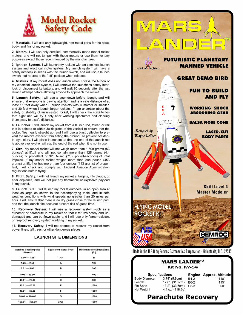
1. Materials. I will use only lightweight, non-metal parts for the nose, body, and fins of my rocket.
2. Motors. I will use only certified, commercially-made model rocket motors, and will not tamper with these motors or use them for any purposes except those recommended by the manufacturer.
3. Ignition System. I will launch my rockets with an electrical launch system and electrical motor igniters. My launch system will have a safety interlock in series with the launch switch, and will use a launch switch that returns to the "off" position when released.
4. Misfires. If my rocket does not launch when I press the button of my electrical launch system, I will remove the launcher's safety inter-lock or disconnect its battery, and will wait 60 seconds after the last launch attempt before allowing anyone to approach the rocket.
5. Launch Safety. I will use a countdown before launch, and will ensure that everyone is paying attention and is a safe distance of at least 15 feet away when I launch rockets with D motors or smaller, and 30 feet when I launch larger rockets. If I am uncertain about the safety or stability of an untested rocket, I will check the stability be-fore flight and will fly it only after warning spectators and clearing them away to a safe distance.
6. Launcher. I will launch my rocket from a launch rod, tower, or rail that is pointed to within 30 degrees of the vertical to ensure that the rocket flies nearly straight up, and I will use a blast deflector to pre-vent the motor's exhaust from hitting the ground. To prevent acciden-tal eye injury, I will place launchers so that the end of the launch rod is above eye level or will cap the end of the rod when it is not in use.
7. Size. My model rocket will not weigh more than 1,500 grams (53 ounces) at liftoff and will not contain more than 125 grams (4.4 ounces) of propellant or 320 N-sec (71.9 pound-seconds) of total impulse. If my model rocket weighs more than one pound (453 grams) at liftoff or has more than four ounces (113 grams) of propel-lant, I will check and comply with Federal Aviation Administration regulations before flying.
8. Flight Safety. I will not launch my rocket at targets, into clouds, or near airplanes, and will not put any flammable or explosive payload in my rocket.
9. Launch Site. I will launch my rocket outdoors, in an open area at least as large as shown in the accompanying table, and in safe weather conditions with wind speeds no greater than 20 miles per hour. I will ensure that there is no dry grass close to the launch pad, and that the launch site does not present risk of grass fires.
10. Recovery System. I will use a recovery system such as a streamer or parachute in my rocket so that it returns safely and un-damaged and can be flown again, and I will use only flame-resistant or fireproof recovery system wadding in my rocket.
11. Recovery Safety. I will not attempt to recover my rocket from power lines, tall trees, or other dangerous places.
LAUNCH SITE DIMENSIONS
Installed Total Impulse (N-sec)
Equivalent Motor Type Minimum Site Dimensions (ft.)
0.00 — 1.25 1/4A 50
1.26 — 2.50 A 100
2.51 — 5.00 B 200
5.01 — 10.00 C 400
10.01 — 20.00 D 500
20.01 — 40.00 E 1000
40.01 — 80.00 F 1000
80.01 — 160.00 G 1000
160.01 — 320.00 2 Gs 1500
MARS LANDER™
Kit No. KV-54
Specifications Body Diameter 3.74” (5.9cm) Length 12.6” (31.9cm) Fin Span 13.2” (33.5cm) Net Weight 4.1 oz. (116.2g)
Engine Approx. Altitude B4-2 110’ B6-2 115’ C6-3 360’
Parachute Recovery
FUTURISTIC PLANETARY
MANNED VEHICLE
GREAT DEMO BIRD
FUN TO BUILD AND FLY
WORKING SHOCK ABSORBING GEAR
BALSA NOSE CONE
LASER-CUT
BODY PARTS
Skill Level 4
Master Modeler
Made in the U.S.A by Semroc Astronautics Corporation - Knightdale, N.C. 27545
Designed by Wayne Kellner

What is a Retro-Repro™?
A Retro-Repro™ is a retro reproduction of an out-of-
production model rocket kit. It is a close approxima-
tion of a full scale model of an early historically sig-
nificant model rocket kit from one of the many com-
panies that pioneered the hobby over the past half
century. A Retro-Repro™ is not a true clone or iden-
tical copy of the original. It incorporates improve-
ments using modern technology, while keeping the
flavor and build appeal of the early kits.
Copyright © 2006 Semroc Astronautics Corporation
Box 1271 Knightdale, NC 27545 (919) 266-1977
March 9, 2006 Original Release
May 27, 2006 Revised
About Estes Industries, Inc.
In July 1958, G. Harry Stine of Model Missiles, Inc.
in Denver, Colorado approached Vern Estes about
making model rocket engines for them. On January
15, 1959, Vern’s automated model rocket engine
fabricating machine, “Mabel”, produced the first of
many millions of Estes model rocket engines. In
1960, Estes was producing more engines than
Model Missiles could sell. Vern and his wife Gleda
opened a mail order rocket company and intro-
duced the Astron Scout and Astron Mark.
In 1961, a catalog was mimeographed and hand
stitched on Gleda’s sewing machine. Later that
year, Estes Industries had outgrown the confined
space in Denver. In December 1961, the entire op-
eration was moved to an old farm in Penrose, Colo-
rado quickly establishing the small town as the
“Model Rocket Capital of the World.”
Estes Industries was sold to Damon in September
1969. The name Estes is synonymous with model
rocketry. Almost everyone remembers growing up
firing Estes rockets or knowing someone that did.
Estes Industries has introduced millions of young-
sters of all ages to model rocketry for almost half a
century.
If you are not 100% satisfied with your Semroc
product, we will make it right by providing what-
ever you consider fair, from refund to replacement.
Contact us at:
Semroc Astronautics Corporation Customer Service Department
P.O. Box 1271
Knightdale, North Carolina 27545
100% SATISFACTION
GUARANTEE
LIMITATION OF LIABILITY
Model rockets are not toys, but are functional rock-
ets made of lightweight materials and are launched
with NAR or Tripoli safety certified model rocket
motors, electrically ignited and flown in accordance
with the NAR Model Rocket Safety Code. If mis-
used, model rockets can cause serious injury and
property damage. Semroc certifies that it has exer-
cised reasonable diligence in the design and manu-
facture of its products. Semroc cannot assume any
liability for the storage, transportation, or usage of
its products. Semroc shall not be held responsible
for any personal injury or property damage whatso-
ever arising out of the handling, storage, use, or
misuse of our products. The buyer assumes all risks
and liabilities therefrom and accepts and uses Sem-
roc products on these conditions.
Your purchase and use of any Semroc products is
construed as your agreement to and acceptance of
these terms. If you do not agree to these terms and
conditions, you must return the product, unused,
for refund or credit.
JOIN THE NAR!
Sign up online at www.nar.org to join
the premier model rocketry organiza-
tion. Semroc fully supports the Na-
tional Association of Rocketry and rec-
ognizes it as the sport’s official voice.
The NAR is the oldest and largest
sport rocketry organization in the
world. Since 1957 over 80,000 serious
sport rocket modelers have joined the
NAR to take advantage of the fun and
excitement of organized rocketry. It is always more
fun if you fly with friends. The Sport Rocketry
magazine is one of the best ways to keep informed
of new developments in the hobby. Check online at
www.semroc.com/nar for promotions just for NAR
members.
FLIGHT PREPPING
65. The Mars Lander™ is designed to fly with
B6-2, B4-2, and C6-3 engines only. Only fly your
Mars Lander™ in little or no wind. The Mars Lan-
der™ is marginally stable due to its short, squat
shape. Without an engine, the dry Center of Gravity
(CG) should be no more than 7.1” from the top of
the nose cone. That is about at the top of the gear
hub slots. Use two pencils to balance the Mars Lan-
der using the slots as fulcrum points. If the CG is
more than 7.1” from the nose cone tip, a small
amount of weight may be required in the nose cone
to make the Mars Lander™ stable.
68. Refer to the model rocket engine manu-
facturer’s instructions to complete the engine prep-
ping. Different engines have different igniters and
methods of hooking them up to the launch control-
lers.
69. Carefully check all parts of your rocket
before each flight as a part of your pre-flight check-
list. Launch the Mars Lander™ from a 1/8” diameter
by 36” long or longer launch rod. Aim the rod as
close to vertical as possible. The Mars Lander™ can
not recover from any angle of attack greater than
about 15 degrees. Any wind or flights off vertical
can result in unstable flights!
70. After each flight, remove the spent en-
gine casing and clean the model thoroughly for
many hours of fun flying with your Mars Lander™!
66. Pack the recovery wadding from the top
of the body tube. Use a sufficient quantity to protect
the parachute, but not too much that it will interfere
with the proper deployment of the parachute. For
best results, only push the recovery wadding down
far enough to allow room for the chute and cords.
67. Fold the parachute and pack it and the
shock cord on top of the recovery wadding. Slide
the nose cone into place, making sure it does not
pinch the shock cord or parachute. If you are flying
with a B4-2 or a B6-2 engine, the parachute must be
packed very loosely. Do not wrap the lines and
shock cord around the parachute or it will not have
time to unroll. The maximum altitude is only about
100 feet and a tightly rolled chute will take more
distance to unroll before impact.
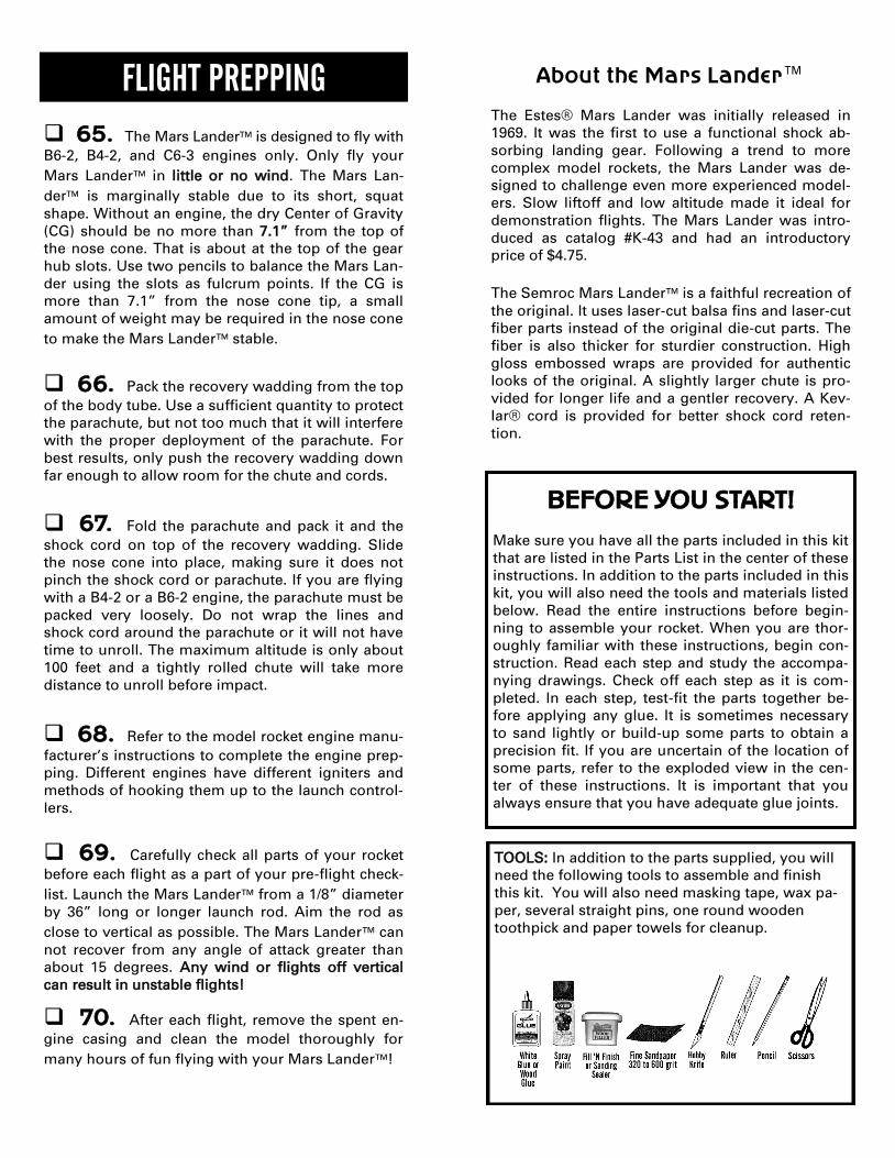
TOOLS: In addition to the parts supplied, you will
need the following tools to assemble and finish
this kit. You will also need masking tape, wax pa-
per, several straight pins, one round wooden
toothpick and paper towels for cleanup.
About the Mars Lander™
The Estes® Mars Lander was initially released in
1969. It was the first to use a functional shock ab-
sorbing landing gear. Following a trend to more
complex model rockets, the Mars Lander was de-
signed to challenge even more experienced model-
ers. Slow liftoff and low altitude made it ideal for
demonstration flights. The Mars Lander was intro-
duced as catalog #K-43 and had an introductory
price of $4.75.
The Semroc Mars Lander™ is a faithful recreation of
the original. It uses laser-cut balsa fins and laser-cut
fiber parts instead of the original die-cut parts. The
fiber is also thicker for sturdier construction. High
gloss embossed wraps are provided for authentic
looks of the original. A slightly larger chute is pro-
vided for longer life and a gentler recovery. A Kev-
lar® cord is provided for better shock cord reten-
tion.
BEFORE YOU START!
Make sure you have all the parts included in this kit
that are listed in the Parts List in the center of these
instructions. In addition to the parts included in this
kit, you will also need the tools and materials listed
below. Read the entire instructions before begin-
ning to assemble your rocket. When you are thor-
oughly familiar with these instructions, begin con-
struction. Read each step and study the accompa-
nying drawings. Check off each step as it is com-
pleted. In each step, test-fit the parts together be-
fore applying any glue. It is sometimes necessary
to sand lightly or build-up some parts to obtain a
precision fit. If you are uncertain of the location of
some parts, refer to the exploded view in the cen-
ter of these instructions. It is important that you
always ensure that you have adequate glue joints.
1. These instructions are presented in a logical
order to help you put your Mars Lander™ together
quickly and efficiently. Check off each step as you
complete it and enjoy putting this kit together.
ASSEMBLY
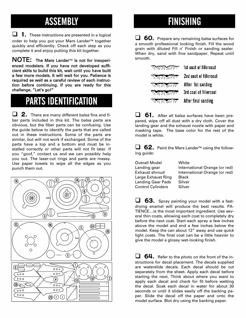
2. There are many different balsa fins and fi-
ber parts included in this kit. The balsa parts are
obvious, but the fiber parts can be confusing. Use
the guide below to identify the parts that are called
out in these instructions. Some of the parts are
similar, but will not work if exchanged. Some of the
parts have a top and a bottom and must be in-
stalled correctly or other parts will not fit later. If
you “goof,” contact us and we can possibly help
you out. The laser-cut rings and parts are messy.
Use paper towels to wipe all the edges as you
punch them out.
PARTS IDENTIFICATION
NOTE: The Mars Lander™ is not for inexperi-
enced modelers. If you have not developed suffi-
cient skills to build this kit, wait until you have built
a few more models. It will wait for you. Patience is
required as well as a careful review of each instruc-
tion before continuing. If you are ready for this
challenge, “Let’s go!”
FINISHING
60. Prepare any remaining balsa surfaces for
a smooth professional looking finish. Fill the wood
grain with diluted Fill n’ Finish or sanding sealer.
When dry, sand with fine sandpaper. Repeat until
smooth.
61. After all balsa surfaces have been pre-
pared, wipe off all dust with a dry cloth. Cover the
landing gear and the exhaust nozzle with paper and
masking tape. The base color for the rest of the
model is white.
63. Spray painting your model with a fast-
drying enamel will produce the best results. PA-
TIENCE…is the most important ingredient. Use sev-
eral thin coats, allowing each coat to completely dry
before the next coat. Start each spray a few inches
above the model and end a few inches below the
model. Keep the can about 12” away and use quick
light coats. The final coat can be a little heavier to
give the model a glossy wet-looking finish.
62. Paint the Mars Lander™ using the follow-
ing guide:
Overall Model White
Landing gear International Orange (or red)
Exhaust shroud International Orange (or red)
Large Exhaust Ring Black
Landing Gear Pads Silver
Control Cylinders Silver
64. Refer to the photo on the front of the in-
structions for decal placement. The decals supplied
are waterslide decals. Each decal should be cut
separately from the sheet. Apply each decal before
starting the next. Think about where you want to
apply each decal and check for fit before wetting
the decal. Soak each decal in water for about 30
seconds or until it slides easily off the backing pa-
per. Slide the decal off the paper and onto the
model surface. Blot dry using the backing paper.
RECOVERY SYSTEM
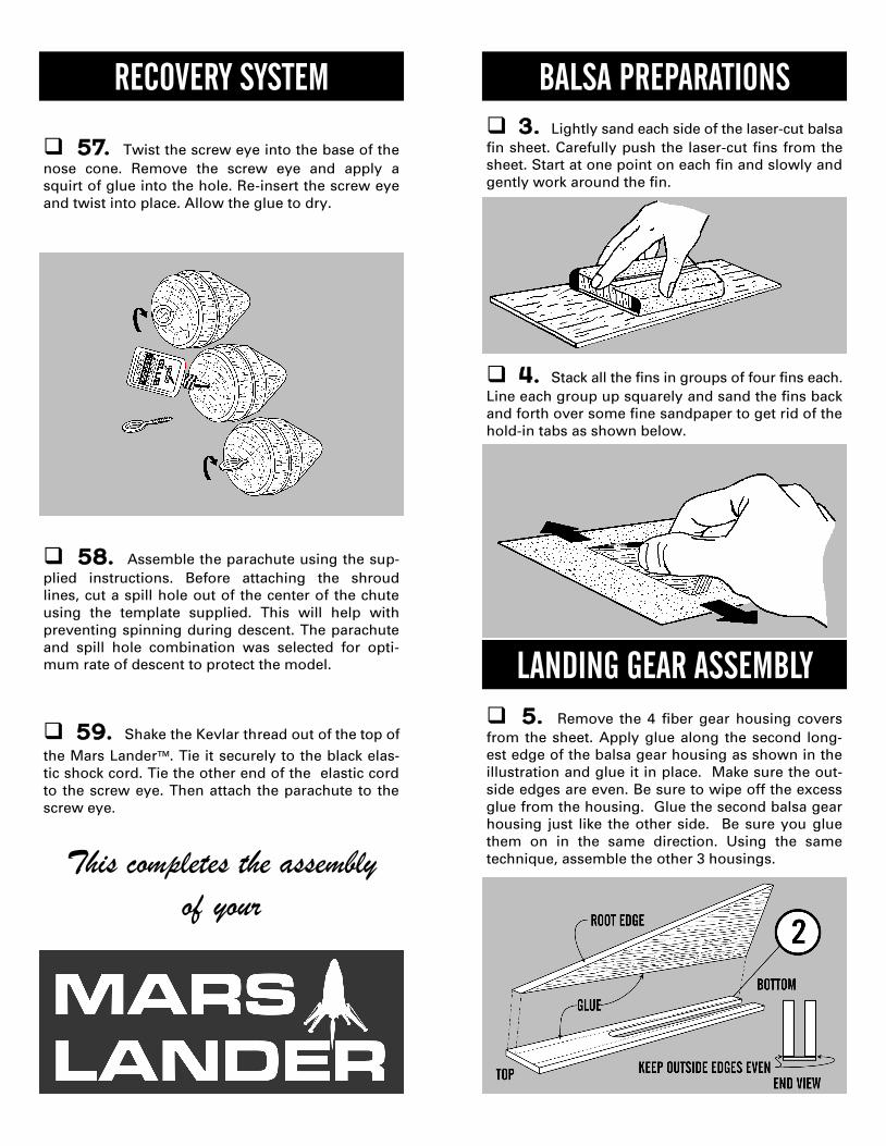
57. Twist the screw eye into the base of the
nose cone. Remove the screw eye and apply a
squirt of glue into the hole. Re-insert the screw eye
and twist into place. Allow the glue to dry.
58. Assemble the parachute using the sup-
plied instructions. Before attaching the shroud
lines, cut a spill hole out of the center of the chute
using the template supplied. This will help with
preventing spinning during descent. The parachute
and spill hole combination was selected for opti-
mum rate of descent to protect the model.
59. Shake the Kevlar thread out of the top of
the Mars Lander™. Tie it securely to the black elas-
tic shock cord. Tie the other end of the elastic cord
to the screw eye. Then attach the parachute to the
screw eye.
This completes the assembly
of your
3. Lightly sand each side of the laser-cut balsa
fin sheet. Carefully push the laser-cut fins from the
sheet. Start at one point on each fin and slowly and
gently work around the fin.
4. Stack all the fins in groups of four fins each.
Line each group up squarely and sand the fins back
and forth over some fine sandpaper to get rid of the
hold-in tabs as shown below.
5. Remove the 4 fiber gear housing covers
from the sheet. Apply glue along the second long-
est edge of the balsa gear housing as shown in the
illustration and glue it in place. Make sure the out-
side edges are even. Be sure to wipe off the excess
glue from the housing. Glue the second balsa gear
housing just like the other side. Be sure you glue
them on in the same direction. Using the same
technique, assemble the other 3 housings.
LANDING GEAR ASSEMBLY
BALSA PREPARATIONS
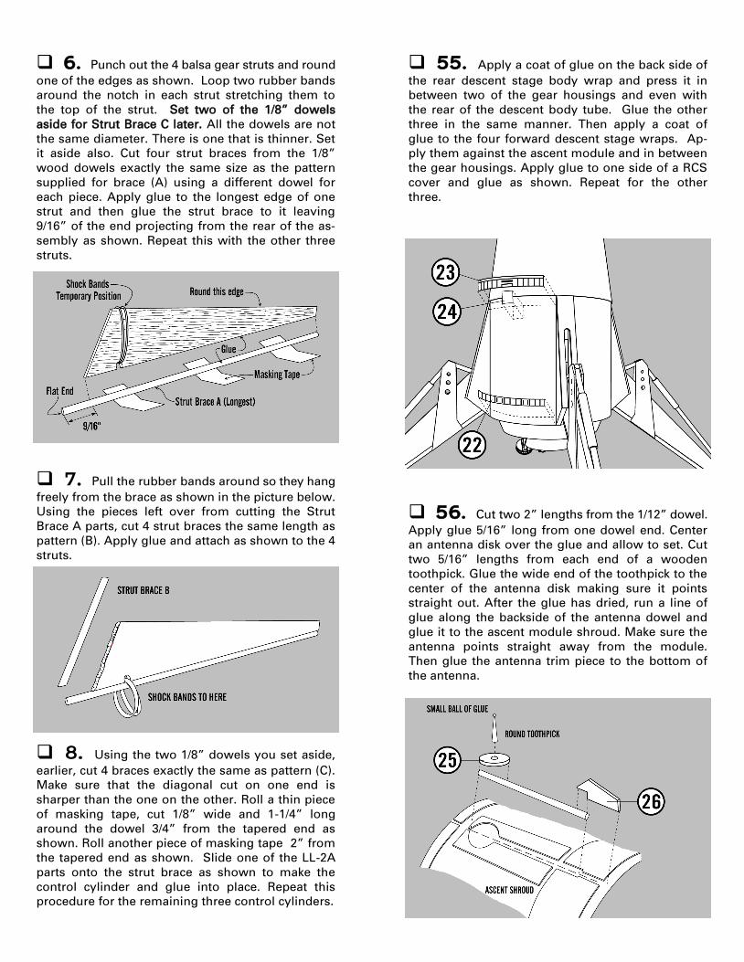
7. Pull the rubber bands around so they hang
freely from the brace as shown in the picture below.
Using the pieces left over from cutting the Strut
Brace A parts, cut 4 strut braces the same length as
pattern (B). Apply glue and attach as shown to the 4
struts.
8. Using the two 1/8” dowels you set aside,
earlier, cut 4 braces exactly the same as pattern (C).
Make sure that the diagonal cut on one end is
sharper than the one on the other. Roll a thin piece
of masking tape, cut 1/8” wide and 1-1/4” long
around the dowel 3/4” from the tapered end as
shown. Roll another piece of masking tape 2” from
the tapered end as shown. Slide one of the LL-2A
parts onto the strut brace as shown to make the
control cylinder and glue into place. Repeat this
procedure for the remaining three control cylinders.
6. Punch out the 4 balsa gear struts and round
one of the edges as shown. Loop two rubber bands
around the notch in each strut stretching them to
the top of the strut. Set two of the 1/8” dowels
aside for Strut Brace C later. All the dowels are not
the same diameter. There is one that is thinner. Set
it aside also. Cut four strut braces from the 1/8”
wood dowels exactly the same size as the pattern
supplied for brace (A) using a different dowel for
each piece. Apply glue to the longest edge of one
strut and then glue the strut brace to it leaving
9/16” of the end projecting from the rear of the as-
sembly as shown. Repeat this with the other three
struts.
55. Apply a coat of glue on the back side of
the rear descent stage body wrap and press it in
between two of the gear housings and even with
the rear of the descent body tube. Glue the other
three in the same manner. Then apply a coat of
glue to the four forward descent stage wraps. Ap-
ply them against the ascent module and in between
the gear housings. Apply glue to one side of a RCS
cover and glue as shown. Repeat for the other
three.
56. Cut two 2” lengths from the 1/12” dowel.
Apply glue 5/16” long from one dowel end. Center
an antenna disk over the glue and allow to set. Cut
two 5/16” lengths from each end of a wooden
toothpick. Glue the wide end of the toothpick to the
center of the antenna disk making sure it points
straight out. After the glue has dried, run a line of
glue along the backside of the antenna dowel and
glue it to the ascent module shroud. Make sure the
antenna points straight away from the module.
Then glue the antenna trim piece to the bottom of
the antenna.

54. Slide the engine nozzle shroud onto the
engine mount tube making sure that the engine
hook passes through the notches in the rings. Posi-
tion the large end of the nozzle even with the en-
gine tube end. Make sure that the engine hook
moves freely in the notches. Glue into place and
hold until it sets.
52. Next run a line of glue around the edge of
the ascent bulkhead and around the forward end of
the parachute tube. Slide on the command module
making sure the launch lug is through the notch
and glue into place. When the glue is dry cut away
the top of the launch lug at an angle so that it is
flush with the shroud.
53. Apply a thin line of glue around the large
end of the descent stage shroud. Pass the launch
lug through the bulkhead hole and glue into place
against the descent stage bulkhead. Be sure that it
is centered and hold until it sets. Trim the bottom of
the launch lug flush with the bulkhead.
9. Mark each strut exactly 2- 7/16” from the
protruding end. Take one gear strut support and
glue it into position as shown against the landing
gear. Hold into place until the glue sets. Do the
same with the other three landing gears.
10. Apply glue to the gear support as shown
in the illustration below. Glue the strut brace on
with the control cylinder closest to the strut sup-
port. Be sure to glue the assembly exactly as
shown below and repeat for the other 3 assemblies.
11. Glue the other gear support on to the as-
sembly exactly as you did the first one and hold in
place with masking tape until it sets. Repeat on the
other 3 assemblies.
13. Apply glue to the edge of the landing pad
ring (EB-20B) and center it on the lower pad disk (5).
Apply glue to the top edge of the landing pad ring.
Center the upper pad ring (6) on the landing pad
ring. Wipe off all excess glue. Make 3 more pads
exactly the same.
12. Cut the strut wraps from the pattern sheet
supplied. Apply glue to the printed side and center
it on the bottom of Strut Brace (A) just before the
slot that contains the shock bands. Repeat with the
other 3 assemblies. Be sure not to get glue on the
shock bands.
51. Slide the ascent module part way onto the
parachute tube. Run a line of glue around the mod-
ule’s internal ring. Slide the internal ring into the
descent stage until the rear of the shroud is up
against the front of the gear housings. Then apply
a fillet of glue around the ascent module forward
bulkhead at the body tube joint.
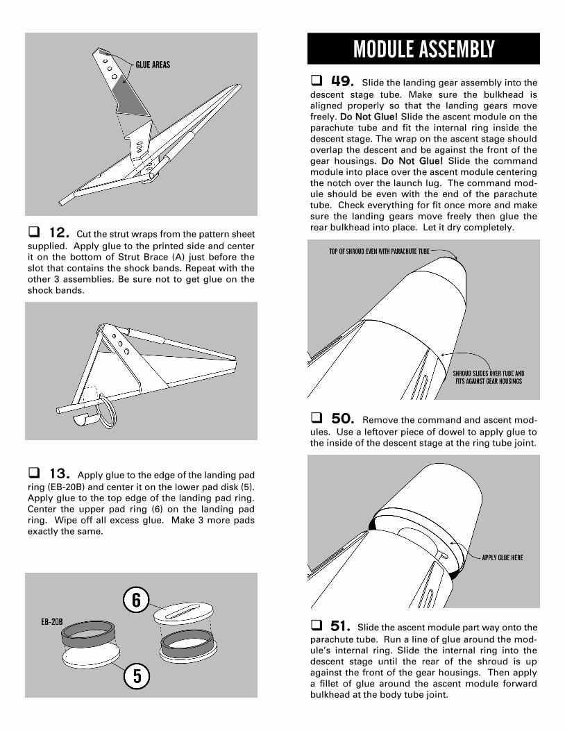
49. Slide the landing gear assembly into the
descent stage tube. Make sure the bulkhead is
aligned properly so that the landing gears move
freely. Do Not Glue! Slide the ascent module on the
parachute tube and fit the internal ring inside the
descent stage. The wrap on the ascent stage should
overlap the descent and be against the front of the
gear housings. Do Not Glue! Slide the command
module into place over the ascent module centering
the notch over the launch lug. The command mod-
ule should be even with the end of the parachute
tube. Check everything for fit once more and make
sure the landing gears move freely then glue the
rear bulkhead into place. Let it dry completely.
MODULE ASSEMBLY
50. Remove the command and ascent mod-
ules. Use a leftover piece of dowel to apply glue to
the inside of the descent stage at the ring tube joint.
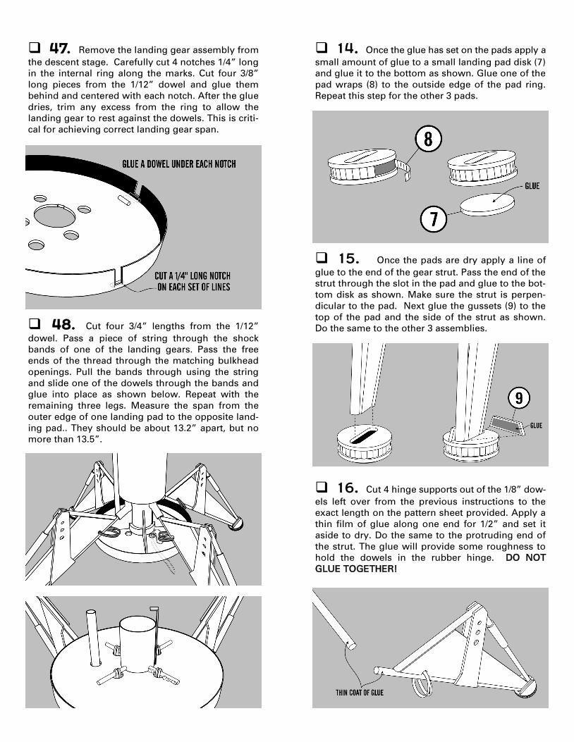
47. Remove the landing gear assembly from
the descent stage. Carefully cut 4 notches 1/4” long
in the internal ring along the marks. Cut four 3/8”
long pieces from the 1/12” dowel and glue them
behind and centered with each notch. After the glue
dries, trim any excess from the ring to allow the
landing gear to rest against the dowels. This is criti-
cal for achieving correct landing gear span.
48. Cut four 3/4” lengths from the 1/12”
dowel. Pass a piece of string through the shock
bands of one of the landing gears. Pass the free
ends of the thread through the matching bulkhead
openings. Pull the bands through using the string
and slide one of the dowels through the bands and
glue into place as shown below. Repeat with the
remaining three legs. Measure the span from the
outer edge of one landing pad to the opposite land-
ing pad.. They should be about 13.2” apart, but no
more than 13.5”.
15. Once the pads are dry apply a line of
glue to the end of the gear strut. Pass the end of the
strut through the slot in the pad and glue to the bot-
tom disk as shown. Make sure the strut is perpen-
dicular to the pad. Next glue the gussets (9) to the
top of the pad and the side of the strut as shown.
Do the same to the other 3 assemblies.
16. Cut 4 hinge supports out of the 1/8” dow-
els left over from the previous instructions to the
exact length on the pattern sheet provided. Apply a
thin film of glue along one end for 1/2” and set it
aside to dry. Do the same to the protruding end of
the strut. The glue will provide some roughness to
hold the dowels in the rubber hinge. DO NOT
GLUE TOGETHER!
14. Once the glue has set on the pads apply a
small amount of glue to a small landing pad disk (7)
and glue it to the bottom as shown. Glue one of the
pad wraps (8) to the outside edge of the pad ring.
Repeat this step for the other 3 pads.

17. While the glue is drying, insert one plastic
bearing in each of the rubber hinges. Use your fin-
gers to slowly work the bearing to the center of
each rubber hinge tube. When all the glue is dry,
slide one of the flexible hinge tubes onto the strut
brace. Push it until the bearing seats against the
dowel. If the bearing does not touch the dowel, trim
a small amount off the end of the hinge tubing, re-
center the bearing and try again. Then insert the
hinge support into the other end of the tube until it
touches the bearing from the other side. Repeat
with the other 3 landing gears.
19. Now that the landing gears are assem-
bled and the glue is dry you may apply sanding
sealer to them. Apply sparingly to keep the weight
down. We recommend using Elmer's Fill and Finish
for sealing. You may apply it to all surfaces except
for the hinge and the hinge support. They must
remain unfilled and unpainted. After you apply the
sealer and sand the landing gears smooth you can
paint them. Paint the gear International Orange or
red. Paint the control cylinders and landing pads
silver.
18. After the glue has dried on the 4 landing
gears, make a glue fillet on all the strut brace joints
as shown it the illustration. Wipe it with your finger
making a fillet and allow the glue to set. Do the
same to both sides of the landing gear on the re-
maining three landing gears.
BREAK TIME!!
44. Set the small end of the engine shroud
down on a piece of wax paper. Insert the small noz-
zle spacing ring (20) and slide it down until it is
flush with the bottom of the shroud. Make sure the
engine hook notch is centered on the shroud joint.
Run a bead of glue around the ring shroud joint and
allow to dry.
45. Run a bead of glue around the inside of
the large opening in the shroud. Place the large
nozzle spacing ring (21) in the shroud and glue it
into place. Make sure that the engine hook notches
are in line with each other.
46. Next trim off the last 1/4” of each landing
gear opening in the descent body tube. Then slide
the entire landing gear assembly into the rear of the
descent stage. The aft bulkhead should be 1/16”
inward from the rear of the body tube. Align so
that the landing gears can move freely. Without
moving the bulkhead mark each exposed section of
the internal ring. The marks should be at the inside
edge of each gear housing. The landing gear are
not shown in the illustration below.
43. Form the engine nozzle shroud the same
as in step #34. Apply glue to the overhang and
press in position and hold until it sets. Then allow
the glue to dry.
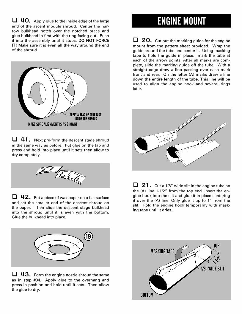
40. Apply glue to the inside edge of the large
end of the ascent module shroud. Center the nar-
row bulkhead notch over the notched brace and
glue bulkhead in first with the ring facing out. Push
it into the assembly until it stops. DO NOT FORCE
IT! Make sure it is even all the way around the end
of the shroud.
41. Next pre-form the descent stage shroud
in the same way as before. Put glue on the tab and
press and hold into place until it sets then allow to
dry completely.
42. Put a piece of wax paper on a flat surface
and set the smaller end of the descent shroud on
the paper. Then slide the descent stage bulkhead
into the shroud until it is even with the bottom.
Glue the bulkhead into place.
20. Cut out the marking guide for the engine
mount from the pattern sheet provided. Wrap the
guide around the tube and center it. Using masking
tape to hold the guide in place, mark the tube at
each of the arrow points. After all marks are com-
plete, slide the marking guide off the tube. With a
straight edge draw a line passing over each mark
front and rear. On the letter (A) marks draw a line
down the entire length of the tube. This line will be
used to align the engine hook and several rings
later.
21. Cut a 1/8” wide slit in the engine tube on
the (A) line 1-1/2” from the top end. Insert the en-
gine hook into the slit and glue it in place centering
it over the (A) line. Only glue it up to 1” from the
slit. Hold the engine hook temporarily with mask-
ing tape until it dries.
ENGINE MOUNT
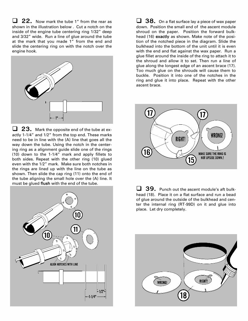
22. Now mark the tube 1” from the rear as
shown in the illustration below . Cut a notch on the
inside of the engine tube centering ring 1/32” deep
and 3/32” wide. Run a line of glue around the tube
at the mark that you made 1” from the end and
slide the centering ring on with the notch over the
engine hook.
23. Mark the opposite end of the tube at ex-
actly 1-1/4” and 1/2” from the top end. These marks
need to be in line with the (A) line that goes all the
way down the tube. Using the notch in the center-
ing ring as a alignment guide slide one of the rings
(10) down to the 1-1/4” mark and apply fillets to
both sides. Repeat with the other ring (10) glued
even with the 1/2” mark. Make sure both notches in
the rings are lined up with the line on the tube as
shown. Then slide the cap ring (11) onto the end of
the tube aligning the small hole over the (A) line. It
must be glued flush with the end of the tube.
38. On a flat surface lay a piece of wax paper
down. Position the small end of the ascent module
shroud on the paper. Position the forward bulk-
head (16) exactly as shown. Make note of the posi-
tion of the notched piece in the diagram. Slide the
bulkhead into the bottom of the unit until it is even
with the end and flat against the wax paper. Run a
glue fillet around the inside of the ring to attach it to
the shroud and allow it to set. Then run a line of
glue along the longest edge of an ascent brace (17).
Too much glue on the shrouds will cause them to
buckle. Position it into one of the notches in the
ring and glue it into place. Repeat with the other
ascent brace.
39. Punch out the ascent module’s aft bulk-
head (18). Place it on a flat surface and run a bead
of glue around the outside of the bulkhead and cen-
ter the internal ring (RT-99D) on it and glue into
place. Let dry completely.

35. Glue the shroud together by applying
glue to the shroud tab and align the two sides to-
gether. Hold in place until it sets up and then leave
to dry. White glue works best for shrouds since it
does not shrink as much as some glues.
36. Follow the same procedure that you just
did in step 35 to the command module shroud. Af-
ter the glue has set for several minutes then press
the Command module bulkhead into the larger
opening and glue into place. Make sure the bulk-
head is even with the end of the shroud. Sanding
may be necessary to get the proper fit.
37. Punch out the notched ascent module
brace (15). Apply glue to the longest straight edge
and glue the brace to the shroud joint so that the
notched end is toward the large end of the shroud.
Hold in place until it sets and make sure it points
straight away from the shroud.
24. Punch out the balsa and paper (1) gear
housing spacers. Glue the two together and let dry.
Insert the spacer in between the groove in the gear
housing. Wrap a piece of sandpaper around the
chute tube (BT-60FG) and round the edges of the
gear housing by sanding them back and forth
against the tube. Do the same to the other three
housings. Make sure that the bottom edges of the
gear housings fit smoothly against the descent
stage tube (BT-100CE.) The spacer will be discarded
when you are finished with it.
MAIN ASSEMBLY
25. Cut out the descent stage marking guide.
Wrap the guide around the descent stage tube (BT-
100CE) and tape with masking tape. Center it over
the tube and mark the tube at each of the arrow
points. Draw a line on the tube around each of the
landing gear openings with a straight edge. Very
carefully cut out the landing gear openings in the
body tube except for the last 1/4” of the tube. The
tube will become very flexible and hard to work
with. Patience is required to avoid cutting through
the large tube. (Refer to illustration)
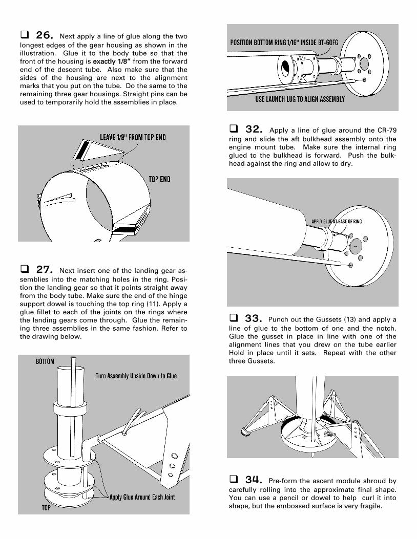
26. Next apply a line of glue along the two
longest edges of the gear housing as shown in the
illustration. Glue it to the body tube so that the
front of the housing is exactly 1/8” from the forward
end of the descent tube. Also make sure that the
sides of the housing are next to the alignment
marks that you put on the tube. Do the same to the
remaining three gear housings. Straight pins can be
used to temporarily hold the assemblies in place.
27. Next insert one of the landing gear as-
semblies into the matching holes in the ring. Posi-
tion the landing gear so that it points straight away
from the body tube. Make sure the end of the hinge
support dowel is touching the top ring (11). Apply a
glue fillet to each of the joints on the rings where
the landing gears come through. Glue the remain-
ing three assemblies in the same fashion. Refer to
the drawing below.
33. Punch out the Gussets (13) and apply a
line of glue to the bottom of one and the notch.
Glue the gusset in place in line with one of the
alignment lines that you drew on the tube earlier
Hold in place until it sets. Repeat with the other
three Gussets.
34. Pre-form the ascent module shroud by
carefully rolling into the approximate final shape.
You can use a pencil or dowel to help curl it into
shape, but the embossed surface is very fragile.
32. Apply a line of glue around the CR-79
ring and slide the aft bulkhead assembly onto the
engine mount tube. Make sure the internal ring
glued to the bulkhead is forward. Push the bulk-
head against the ring and allow to dry.

29. Cut out the marking guide for the para-
chute tube and wrap it around the tube. Mark the
tube at each arrow point. Remove the guide and
draw a line down the whole body tube with a
straight edge. Glue the long launch lug (LL-2E) on
the mark you made making sure that one end of the
launch lug is even with the (top) end of the tube.
30. Pass one end of the Kevlar® thread
through the small hole in the Cap Ring (11) and tie
it securely to the closest Hinge Support Dowel. Put
a drop of glue on the knot. Pass the free end into
the engine mount tube to keep it out of the way.
31. After the glue is dry on the launch lug,
slide the descent stage aft bulkhead assembly onto
the rear of the engine mount tube. Center the bulk-
head notch over the engine hook and slid it all the
way to the centering ring. DO NOT GLUE YET, hold
in place. Pass the launch lug through the furthest
hole in the bulkhead as shown. Slide the engine
mount ring assembly into the parachute tube until
the bottom ring is 1/16” inside the tube. Glue the
parachute tube into place.
28. Slide the descent stage bulkhead into the
end of one of the internal body rings and glue into
place by running a fillet on the inside.
NOTE
When the landing gears are put onto the engine
tube they should look like the drawing below.
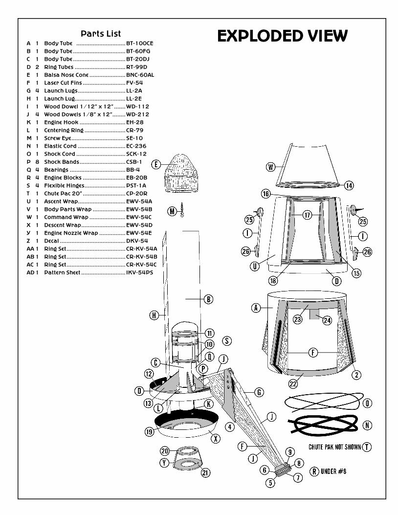
Parts List A 1 Body Tube .............................. BT-100CE
B 1 Body Tube ................................ BT-60FG
C 1 Body Tube ................................ BT-20DJ
D 2 Ring Tubes ............................... RT-99D
E 1 Balsa Nose Cone ...................... BNC-60AL
F 1 Laser Cut Fins .......................... FV-54
G 4 Launch Lugs ............................. LL-2A
H 1 Launch Lug............................... LL-2E
I 1 Wood Dowel 1/12” x 12” ....... WD-112
J 4 Wood Dowels 1/8” x 12”........ WD-212
K 1 Engine Hook ............................ EH-28
L 1 Centering Ring ......................... CR-79
M 1 Screw Eye ................................. SE-10
N 1 Elastic Cord ............................. EC-236
O 1 Shock Cord .............................. SCK-12
P 8 Shock Bands ............................ CSB-1
Q 4 Bearings .................................. BB-4
R 4 Engine Blocks .......................... EB-20B
S 4 Flexible Hinges ......................... PST-1A
T 1 Chute Pac 20” .......................... CP-20R
U 1 Ascent Wrap ............................. EWV-54A
V 1 Body Parts Wrap .................... EWV-54B
W 1 Command Wrap ...................... EWV-54C
X 1 Descent Wrap ........................... EWV-54D
Y 1 Engine Nozzle Wrap ................ EWV-54E
Z 1 Decal ........................................ DKV-54
AA 1 Ring Set .................................... CR-KV-54A
AB 1 Ring Set .................................... CR-KV-54B
AC 1 Ring Set .................................... CR-KV-54C
AD 1 Pattern Sheet ........................... IKV-54PS
EXPLODED VIEW