Fiberglass Pergola Installation Instructions - HB&G … Pergola Installation Instructions 13....
2
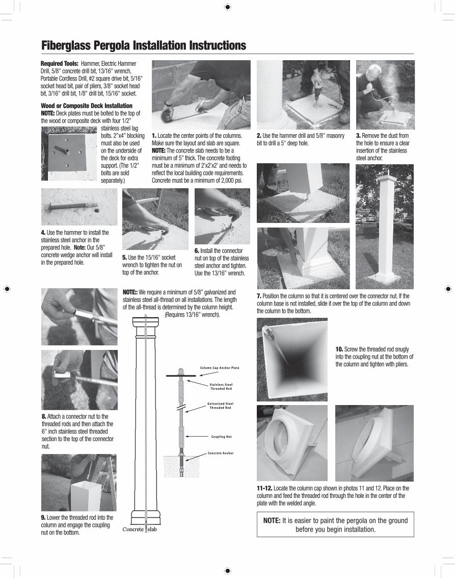
Wood or Composite Deck Installation NOTE: Deck plates must be bolted to the top of the wood or composite deck with four 1/2” stainless steel lag bolts. 2”x4” blocking must also be used on the underside of the deck for extra support. (The 1/2” bolts are sold separately.) Fiberglass Pergola Installation Instructions Required Tools: Hammer, Electric Hammer Drill, 5/8" concrete drill bit, 13/16" wrench, Portable Cordless Drill, #2 square drive bit, 5/16" socket head bit, pair of pliers, 3/8" socket head bit, 3/16" drill bit, 1/8" drill bit, 15/16" socket. 1. Locate the center points of the columns. Make sure the layout and slab are square. NOTE: The concrete slab needs to be a minimum of 5” thick. The concrete footing must be a minimum of 2’x2’x2’ and needs to reflect the local building code requirements. Concrete must be a minimum of 2,000 psi. 2. Use the hammer drill and 5/8" masonry bit to drill a 5" deep hole. 3. Remove the dust from the hole to ensure a clear insertion of the stainless steel anchor. 4. Use the hammer to install the stainless steel anchor in the prepared hole. Note: Our 5/8” concrete wedge anchor will install in the prepared hole. 6. Install the connector nut on top of the stainless steel anchor and tighten. Use the 13/16" wrench. 7. Position the column so that it is centered over the connector nut. If the column base is not installed, slide it over the top of the column and down the column to the bottom. 11-12. Locate the column cap shown in photos 11 and 12. Place on the column and feed the threaded rod through the hole in the center of the plate with the welded angle. 10. Screw the threaded rod snugly into the coupling nut at the bottom of the column and tighten with pliers. 9. Lower the threaded rod into the column and engage the coupling nut on the bottom. 5. Use the 15/16" socket wrench to tighten the nut on top of the anchor. 8. Attach a connector nut to the threaded rods and then attach the 6" inch stainless steel threaded section to the top of the connector nut. NOTE: : We require a minimum of 5/8” galvanized and stainless steel all-thread on all installations. The length of the all-thread is determined by the column height. (Requires 13/16” wrench). NOTE: It is easier to paint the pergola on the ground before you begin installation.
Transcript of Fiberglass Pergola Installation Instructions - HB&G … Pergola Installation Instructions 13....
Wood or Composite Deck Installation NOTE: Deck plates must be bolted to the top of the wood or composite deck with four 1/2”
stainless steel lag bolts. 2”x4” blocking must also be used on the underside of the deck for extra support. (The 1/2” bolts are sold separately.)
Fiberglass Pergola Installation InstructionsRequired Tools: Hammer, Electric Hammer Drill, 5/8" concrete drill bit, 13/16" wrench, Portable Cordless Drill, #2 square drive bit, 5/16" socket head bit, pair of pliers, 3/8" socket head bit, 3/16" drill bit, 1/8" drill bit, 15/16" socket.
1. Locate the center points of the columns. Make sure the layout and slab are square. NOTE: The concrete slab needs to be a minimum of 5” thick. The concrete footing must be a minimum of 2’x2’x2’ and needs to reflect the local building code requirements. Concrete must be a minimum of 2,000 psi.
2. Use the hammer drill and 5/8" masonry bit to drill a 5" deep hole.
3. Remove the dust from the hole to ensure a clear insertion of the stainless steel anchor.
4. Use the hammer to install the stainless steel anchor in the prepared hole. Note: Our 5/8” concrete wedge anchor will install in the prepared hole.
6. Install the connector nut on top of the stainless steel anchor and tighten. Use the 13/16" wrench.
7. Position the column so that it is centered over the connector nut. If the column base is not installed, slide it over the top of the column and down the column to the bottom.
11-12. Locate the column cap shown in photos 11 and 12. Place on the column and feed the threaded rod through the hole in the center of the plate with the welded angle.
10. Screw the threaded rod snugly into the coupling nut at the bottom of the column and tighten with pliers.
9. Lower the threaded rod into the column and engage the coupling nut on the bottom.
5. Use the 15/16" socket wrench to tighten the nut on top of the anchor.
8. Attach a connector nut to the threaded rods and then attach the 6" inch stainless steel threaded section to the top of the connector nut.
NOTE:: We require a minimum of 5/8” galvanized and stainless steel all-thread on all installations. The length of the all-thread is determined by the column height. (Requires 13/16” wrench).
Note: It is easier to paint the pergola on the ground before you begin installation.

Fiberglass Pergola Installation Instructions
13. Tilting the column to one side may make it easier to position the rod so it can be inserted through the hole in the cap. Make sure that the attached angle is oriented properly. Caulk around the center hole. Only finger tighten the stainless steel nut at this time.
14. Install all the headers without decorative rafter tails to the outside of the aluminum angles on top of the columns using the 2.5" hex head stainless steel screws. Set the clutch on the drill so the screw is not stripped.
18. Following the layout pattern on the rafters begin installing the purlins across the top of the rafters using the steel deck screws. Note: The 2.5" stainless steel self-tapping purlin screws will be used on step #18 to attach the purlins to the each rafter. (Requires #2 square drive bit).
Note: On the double rafter support system, the rafter supports will mount on the outside of the double top plate bracket using (4)-2 1/2” hex head self-tapping screws per side (from outside in toward center hole). The header will mount to the angle bracket with 2 1/2” hex head screws. The small flat bracket will mount on top of the header and double rafter support with 3/4” screws or 3/16” pop rivets. (Pop rivet requires 3/16” drill bit.) Note: All the holes in the top plate should be pre-drilled with a 1/8” steel drill bit from the outside from the bracket toward the center hole. Note: On the single rafter support system, the (2) 2.5" hex head stainless self-tapping rafter support screws will be used on each support on step #14 and #15 in our installation instructions. They will attach the single rafter supports and headers to the aluminum 90 degree angled top plate shown in step #13.
19. Set the clutch on the drill to ensure that the screw head does not dimple the top surface of the purlin. Continue across the top of the rafters until all purlins have been installed.
17. Continue working out from the center until the rafters are installed.
16. Starting in the center of the arbor begin installing the rafters with the decorative tails. The headers have fiberglass angles as shown which indicate the rafter location. Note: The 3/4” hex head stainless rafter screws will be used on step # 16 to attach the angle clips to the rafters. (Requires 5/16” socket head bit) *Pre-drilling not required.
20. Using a 15/16" deep well ratchet or open end wrench tighten the nut on top of each column until very tight.
15. Install the rafter supports with the decorative rafter tails on the opposite side of the aluminum angle using 2.5" hex head stainless steel self-tapping screws. Set clutch on the drill so the screw is not stripped.Note: 2.5” screw requires 3/8” socket head bit.
Note: All the holes in the top plate should be pre-drilled with a 1/8" steel drill bit from the inside of the bracket.
*Do not install below grade.* Check your local building code for the building requirements in your area before installation.
* Any deviation from our standard installation shown in these instructions voids all warranties.