Example Program for Crestron - Setup Guide · Example Program for Crestron - Setup Guide - 3 Step...
15
Example Program for Crestron - Setup Guide - May, 2010
Transcript of Example Program for Crestron - Setup Guide · Example Program for Crestron - Setup Guide - 3 Step...

Example Program for Crestron - Setup Guide -
May, 2010

Example Program for Crestron - Setup Guide -
1
Introduction This guide is a step-by-step setup guide to setting up the Yamaha Commercial Audio demonstration programming for Crestron. The program was written to demonstrate the capabilities of Yamaha remote control enabled devices at exhibitions. We have made the code available to assist programmers with example code. You are free to use this code in your own project. The programs have multi-lingual capability and can be configured for different number of devices present.
Please read the caution information on the Yamaha website carefully before proceeding to read on.
Skill Pre-requisites
This guide assumes you are an experienced Crestron programmer and have knowledge of the Yamaha Commercial Audio products which you wish to control. For some products, knowledge of RS-232, MIDI and basic Ethernet networking will also be necessary. The programming is provided "as is" without technical support from Yamaha as an additional resource.
Hardware Pre-requisites
The programming assumes you have some or all of the following hardware. Crestron
PRO2 processor TPS-12W touch panel CNPWSI-75 power supply for touch panel (only required for video playback) TPMC-CH-IMC break-in-box (only required for video playback)
Yamaha 01V96 (MIDI) LS9 (MIDI) M7CL (MIDI) DME24N/DME64N (RS-232) DME4io-C (Ethernet) IMX644 (RS-232) BD-S2900 Blu-ray player (RS-232)
Other Unmanaged Ethernet network switch (10/100Mb) Kenton Electronics THRU-5 MIDI thru device * Kenton Electronics MERGE-4 5 MIDI merge device * *only necessary if multiple consoles are required to be controlled simultaneously.
The programming has been optimised for this hardware. Other Crestron processors or touch screens may be substituted, if the programming is modified suitably and re-compiled, but as this operation has not been tested, no guarantee of performance can be given.

Example Program for Crestron - Setup Guide -
2
Tested Firmware Versions PRO2 processor : 3.155.1240 TPS-12W touch panel : 3.001.0035
The program has been tested using the above firmware combination. Different firmware combination could cause unexpected behaviour. Please refer to the Crestron website to check firmware update history.
File list
Please download and unzip all of these files:
YamahaCA_Crestron_ExampleV1.0_Programming.zip SIMPL Windows files for compiling and uploading to the processor. Written for PRO2.
YamahaCA_Crestron_ExampleV1.0_TP.zip
Files for uploading to the touch panel. Written for TPS-12W. Also supports an XPanel.
YamahaCA_Crestron_ExampleV1.0_DynamicContentRev1.2.zip Language and image files. Transfer using File Manager in the Toolbox application to the
processor.
YamahaCA_Crestron_ExampleV1.0_YamahaDevices.zip Studio manager files for mixers, and configuration files for DME processors and IMX644 installation mixer.
YamahaCA_Crestron_ExampleV1.0_SetupGuide.pdf
This Setup Guide Protocol Specification documents
Each Yamaha device protocol specification document is available as below. DME24N/64N/DME4io-C : Protocol document on Yamaha web site 01V96, M7CL, LS9 : Protocol document on Yamaha web site IMX644 : Described in owner’s manual BD-S2900 : Please contact your nearest Yamaha branch
Assigned IP address IP addresses for all the system components. 192.168.0.101 DME24N 192.168.0.102 DME64N 192.168.0.103 DME4io-C 192.168.0.211 Crestron PRO2 processor 192.168.0.212 Crestron TPS-12 touch panel The device configuration page on the touch panel has pre-configured IP addresses for Yamaha devices. You need to set these identical IP addresses in to the connected Yamaha devices. If you require different IP addresses, these must be modified in the Crestron source code before compiling.

Example Program for Crestron - Setup Guide -
3
Step by step setup
1. Assemble the hardware and connect up both the Crestron & Yamaha components together as shown in the system diagram.
2. Verify all devices have power.
3. Verify all devices are upgraded to the firmware versions mentioned above.
4. Verify there is network activity by looking at the link/activity lights on the network switch.
5. For mixers, configure the MIDI settings as shown in the screenshots below. To save time, we have also prepared Studio Manager files which contain scenes and MIDI configuration settings.
6. For all devices, store scenes or load pre-prepared scenes. 15 are available on the touch panel for the M7CL 15 are available on the touch panel for the 01V96 5 are available on the touch panel for the LS9 8 are available on the touch panel for the DME24N/DME64N/DME4io-C 16 are available on the touch panel for the IMX644, but only 4 memories are necessary as the front panel has 4 memories. (Note that if you select a scene button on the touch panel and there is no scene on the device nothing will happen, which is not very exciting!)
7. Configure IP addresses of the DME4io-C.
8. For DME models, synchronise the provided DME Designer files using DME Designer.
9. Extract Crestron files which are zipped in: - YamahaCA_Crestron_ExampleV1.0_Programming.zip - YamahaCA_Crestron_ExampleV1.0_TP.zip - YamahaCA_Crestron_ExampleV1.0_DynamicContentsRev1.2.zip Then, compile and transfer.
10. Configure the setup pages of the Crestron system as detailed below.
11. Setup completed.
Steps which need further explanation have more information below.

Example Program for Crestron - Setup Guide -
4
Detail of steps Step 1: System Schematic diagrams
The diagram below shows all possible connections with Yamaha devices which are available in this program. You may connect as few or as many Yamaha devices as required.

Example Program for Crestron - Setup Guide -
5
Step 1: System Schematic diagrams (continued)

Example Program for Crestron - Setup Guide -
6
Step 4: Mixing console MIDI configuration
Parameter change TX and RX should be enabled. All others disabled.
Default MIDI channels are as follows: LS9 – channel 1 M7CL – channel 2 01V96 – channel 3 The device configuration page on the touch panel has pre-configured MIDI channels for Yamaha devices. You need to set these identical MIDI channels in to the connected Yamaha devices. If you require different MIDI channels, these must be modified in the Crestron source code before compiling.
Important Note:
Note that at the time of writing, if M7CL is used in addition to another mixer, you MUST use the MIDI-THRU and MERGE units. Daisy-chain connection of MIDI will not work with the M7CL.
Mixer setup screens:
LS9 MIDI settings M7CL MIDI settings
01V96 MIDI Settings – Setup 01V96 MIDI Settings – Host
Note that Studio Manager does not change the MIDI channel,
so this needs to be configured manually.

Example Program for Crestron - Setup Guide -
7
Step 9: Crestron file extracting, compiling and transferring Extract Crestron files which are in the following zip files: - YamahaCA_Crestron_ExampleV1.0_Programming.zip - YamahaCA_Crestron_ExampleV1.0_TP.zip - YamahaCA_Crestron_ExampleV1.0_DynamicContentsRev1.2.zip. This example program requires the memory expansion feature in the PRO2 processor with Compact Flash memory which is a user option in order to serve multi-lingual text files and picture files dynamically to the touch panel. The files in YamahaCA_Crestron_ExampleV1.0_DynamicContentsRev1.2.zip should be copied to the Compact Flash memory. If you don’t carry out this transfer, text and many images won’t be displayed on the touch panel.
In order to upload the dynamic content to the processor, the web pages function need to be enabled first. Follow these steps:
1. Launch Crestron Toolbox and connect to the processor. 2. Go to the Web Pages function from the Functions menu.

Example Program for Crestron - Setup Guide -
8
3. Select the Enable Web Server check box and click Apply.
4. Open the Set User Password dialog and click Disable Password. 5. Select the “VTPro XPanel Web or Mobility Project” check box and locate the project folder. The default page list will be greyed out because the default page has already been specified in VTPro-e. 6. Select the Storage Location: Compact Flash. 7. Type the name of the destination subfolder that will store the project pages. This subfolder will be under the \HTML directory. Click “OK”.
3 45
6
7

Example Program for Crestron - Setup Guide -
9
8. Open the File Manager from the Tools menu.
9. Open Windows Explorer and navigate to the unzipped content. (i.e. the files in YamahaCA_Crestron_ExampleV1.0_DynamicContentsRev1.2.zip) 10. Drag and drop the content from Windows Explorer to the File Manager. 11. Check the content matches (file names and sizes).
Example Program for Crestron - Setup Guide -
10
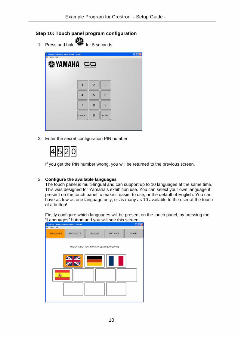
Step 10: Touch panel program configuration
1. Press and hold for 5 seconds.
2. Enter the secret configuration PIN number
4 5 2 0 If you get the PIN number wrong, you will be returned to the previous screen.
3. Configure the available languages The touch panel is multi-lingual and can support up to 10 languages at the same time. This was designed for Yamaha’s exhibition use. You can select your own language if present on the touch panel to make it easier to use, or the default of English. You can have as few as one language only, or as many as 10 available to the user at the touch of a button! Firstly configure which languages will be present on the touch panel, by pressing the “Languages” button and you will see this screen:
Example Program for Crestron - Setup Guide -
11
Press one of the 10 languages buttons. Then select a language flag from the available translations (up to 24) to choose the language used by that button:
Select “BLANK” to clear out a language you don’t want to be present.
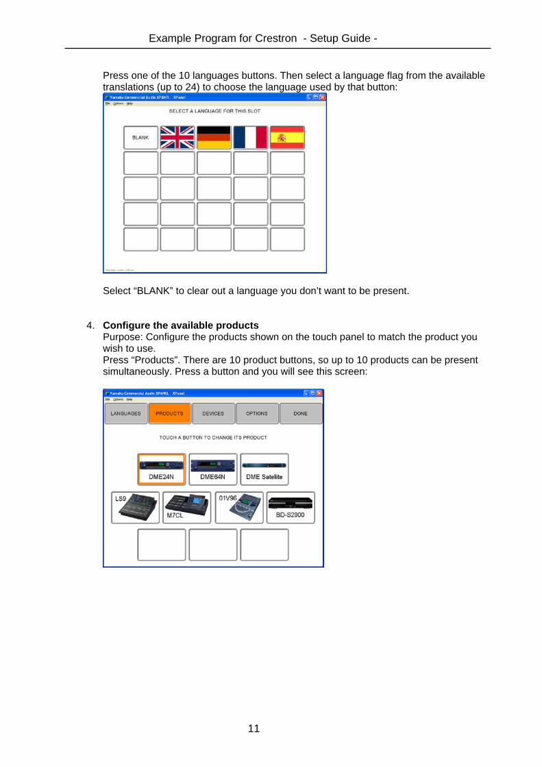
4. Configure the available products Purpose: Configure the products shown on the touch panel to match the product you wish to use. Press “Products”. There are 10 product buttons, so up to 10 products can be present simultaneously. Press a button and you will see this screen:

Example Program for Crestron - Setup Guide -
12
Then select a product from the available products to choose the product used by that button:
5. Verify devices ports, IP addresses and MIDI channels
Press “Devices”. Here you can view and change which serial ports are for which products, view what IP addresses should be configured on the connected products and view which MIDI channels are for which products.
N.B. At the time of writing all settings are fixed except for the choice of device for the serial port.

Example Program for Crestron - Setup Guide -
13
6. Configure Options - Screensaver Here you can set the screensaver. The purpose of the screensaver is not to save the screen, but to enable moving images to attract the attention of exhibition attendees. The options are Blank: No screensaver. Touch panel will go to black when not in use. Slides: A display of product pictures will cycle around with the words “Touch to start” displayed. Video: This allows the Crestron’s video input via the break-in box to be connected to a video source such as a DVD player to show moving images. The video is just for the screensaver and not displayed on any other screens.
7. Configure Options – File Path This sets the path where the product images, text and language flags are loaded from. By default this should be left as the Crestron processor’s IP address.
8. Press “Done” to finish and return to normal operation
Note that the screensaver will still operate after a period of inactivity whilst in the configuration page. This is a deliberate security feature to ensure that the panel is not left in the configuration page by accident.

Example Program for Crestron - Setup Guide -
14
Known issues The following issues are known limitations: BD-S2900 Blu-ray player
Pressing a transport button (play, stop etc), the touch panel takes 5 seconds to update the display, due to the feedback speed from the BD-S2900.
Troubleshooting tips / FAQ Tip:
If you momentarily press the logo, the touch panel will return to the screensaver, without waiting for the time out. This is useful at the end of a demonstration to a customer.
Serial cabling (RS-232)
Q: Does it matter what serial cable I use for what? A: Yes! The BD-S2900 has quite unusual serial wiring! Please use a dedicated cable for it. The DME24N/64N and IMX644 use more conventional “null modem” wiring. Refer to the product manuals for further information.
Touch panel operation
Q: When I press a scene, why does nothing happen? A: The connected device has to have a scene stored in it. Q: The Touch panel shows “connecting…” A: This is waiting or in the process of connecting to the Crestron PRO2 processor. Check Ethernet connections, and network activity lights. If necessary, re-boot the processor and or touch panel.
Video (optional)
Q: How do I get video working on the touch panel? A: You must connect from a video source (e.g. DVD/Blu-ray player) with either composite video (1 BNC), S-Video (Y/C) (2 BNCs) or Component (Y/Pb/Pr) (3 BNCs). Connect the output from the source to the TPMC-CH-IMC break-in-box. Connect the break in box to the touch panel using the black power cable and CAT5 cables for Ethernet and Video. The touch panel does not accept RGB video.
Yamaha CA Support Centre Europe