ESCALATORS - City Lifts - Western Australia Forsyth Street, O’Connor WA 6163 Office +61 8 9331...
20
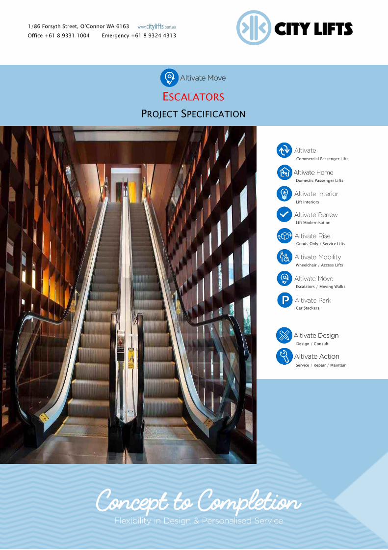
1/86 Forsyth Street, O’Connor WA 6163 Office +61 8 9331 1004 Emergency +61 8 9324 4313 ESCALATORS PROJECT SPECIFICATION Commercial Passenger Lifts Lift Modernisation Lift Interiors Goods Only / Service Lifts Wheelchair / Access Lifts Escalators / Moving Walks Car Stackers Domestic Passenger Lifts Design / Consult Service / Repair / Maintain
Transcript of ESCALATORS - City Lifts - Western Australia Forsyth Street, O’Connor WA 6163 Office +61 8 9331...
1/86 Forsyth Street, O’Connor WA 6163
Office +61 8 9331 1004 Emergency +61 8 9324 4313
ESCALATORS
PROJECT SPECIFICATION
Commercial Passenger Lifts
Lift Modernisation
Lift Interiors
Goods Only / Service Lifts
Wheelchair / Access Lifts
Escalators / Moving Walks
Car Stackers
Domestic Passenger Lifts
Design / Consult
Service / Repair / Maintain

Sep-17 V0 Altivate Move – Escalators – Project Specification P a g e | 2
Contents
Project Description .................................................................................................................................. 4
General Requirements ............................................................................................................................. 4
Manufacturer ....................................................................................................................................... 4
Regulations ......................................................................................................................................... 5
Tender Drawings ................................................................................................................................. 6
Contract Sum....................................................................................................................................... 6
Contract Submittals ............................................................................................................................. 6
Samples............................................................................................................................................... 7
Quality Assurance & Inspections .......................................................................................................... 7
Works for and by Other Trades ................................................................................................................ 7
Building Work ...................................................................................................................................... 7
Electrical Services ................................................................................................................................ 8
Mechanical Services ............................................................................................................................. 9
Fire Protection Services ........................................................................................................................ 9
Design Criteria & Performance Requirements ........................................................................................... 9
Technical Specifications .......................................................................................................................... 9
Escalator Technical Data .................................................................................................................... 10
General ............................................................................................................................................. 10
Truss ................................................................................................................................................. 11
Tracks ............................................................................................................................................... 11
Drive Machine .................................................................................................................................... 11
Step Chains ....................................................................................................................................... 12
Step Tread and Risers ........................................................................................................................ 12
Combplates ....................................................................................................................................... 12
Floor Plates ....................................................................................................................................... 12
Balustrades ........................................................................................................................................ 12
Handrails ........................................................................................................................................... 13
Motors .............................................................................................................................................. 13
Controllers ........................................................................................................................................ 13

Sep-17 V0 Altivate Move – Escalators – Project Specification P a g e | 3
Safety Devices ................................................................................................................................... 14
Key Operated Switches and Emergency Stop Buttons .......................................................................... 15
Materials & Finishes ........................................................................................................................... 15
Moving and Positioning...................................................................................................................... 15
Noise & Vibration............................................................................................................................... 15
Painting & Signs................................................................................................................................. 15
Guards & Barriers............................................................................................................................... 16
Commissioning & Testing .................................................................................................................. 16
Authorities’ Inspections, Fees & Certification ...................................................................................... 17
As-Installed Drawings & Manuals ....................................................................................................... 18
Warranty & Maintenance ........................................................................................................................ 19

Sep-17 V0 Altivate Move – Escalators – Project Specification P a g e | 4
PROJECT DESCRIPTION
Provide an overview of the project and the escalator equipment required.
This work includes the design, supply, delivery, installation, testing, commissioning and
maintenance during the contract period of:
Building name
One single escalator (numbered ???)
GENERAL REQUIREMENTS
MANUFACTURER
The equipment shall be an Altivate Move escalator/s, manufacturer shall be City Lifts, or an
approved equivalent that can meet the performance and quality requirements of the technical
specification. Alternative manufacturers will be assessed according to the following criteria:
Performance.
Quality.
Years of presence in Australia.
Experience with projects of a similar size and nature.
Product warranties.
After sales service and support capability.
Availability of spare parts.
PERFORMANCE
The alternative must meet or exceed the performance parameters of the specified herein.
QUALITY
The alternative must be of equal or better quality to that specified herein with respect of materials,
methods of fabrication, compliance with codes and standards, etc.
PRESENCE IN AUSTRALIA
The alternatives must be sourced from manufacturers that are a registered Australian company
which will be responsible for guaranteeing all product performance and quality warranties.
PROJECT EXPERIENCE
The contractor shall be able to demonstrate that the proposed alternatives have been successfully
employed in projects of a similar size and nature to this project.
PRODUCT WARRANTIES
The proposed alternatives shall be provided with equipment warranties at least equal to that of the
specified herein, but in no case less than 12 months.

Sep-17 V0 Altivate Move – Escalators – Project Specification P a g e | 5
AFTER SALES SERVICE AND SUPPORT CAPABILITY
The contractor shall provide documentary evidence that the alternatives are supported by an
organisation which can provide a level of after sales service and support equivalent to what is
specified herein.
AVAILABILITY OF SPARE PARTS
The contractor shall provide documentary evidence that the alternatives are supported by an
organisation which holds a level of spare parts equivalent to the nominated equipment.
REGULATIONS
AS1170.4 Structural Design Actions – Earthquake Actions in Australia
AS1657 Fixed platforms, walkways, stairways and ladders — Design, construction and installation
AS1735 Lifts, Escalators and moving walks
AS1735.5 Escalators and Moving Walks
AS4836 Safe working on or near low-voltage electrical installations and equipment
AS/NZ 3000 Wiring Rules
EN115-2 Safety of escalators and moving walks — Rules for the improvement of safety of existing
escalators and moving walks
EN13015 Maintenance for Lifts and escalators - Rules for Maintenance instructions
AS/NZS ISO 31000 Risk management
ISO14798 Lifts (elevators), escalators and moving walks - Risk assessment and reduction
methodology
ISO25745 Energy performance of lifts, escalators and moving walks
NCC 2016 National Construction Code
Federal Disability Discrimination Act 1992 (D.D.A.)
Local City Council
Department of Fire and Emergency Service
Worksafe Western Australia

Sep-17 V0 Altivate Move – Escalators – Project Specification P a g e | 6
TENDER DRAWINGS
The architectural drawings show the space provided to accommodate the escalator/s.
CONTRACT SUM
The Tender shall be for a fixed lump sum contract in Australian dollars (AUD), not subject to rise
and fall. No consideration will be given to claims for variations to labour rates, material costs or
exchange rates provided as part of this contract.
CONTRACT SUBMITTALS
A. Brochure. Submit manufacturer’s brochure for each system proposed for use.
B. Shop Drawings. Submit layout drawings or product literature including the following:
1. Maximum loads and reactions on the building structure.
2. Escalator dimensioned layout with detailed construction requirements and all building
works.
3. Details of all finishes.
4. The minimum size of circuit breaker that will carry peak loads without operating.
5. Terminal position and current capacity of submains cables.
6. Submitted in sufficient time for approval and for the Contractor to make arrangements for
access requirements and any penetration or items of equipment to be built in.
Drawings shall be: -
1. Submitted in pdf format.
2. Prepared to comply with Australian Standards for Engineering Drawing Practice, AS1100 to
AS1109 inclusive.
3. Drawn to the following scales - 1:1, 1:5, 1:10, 1:20 for components and 1:50, 1:100 for
locations, except for wiring diagrams, which need not be to scale.
4. Dimensioned in S.I. units.
5. Prepared by competent draftsmen using CAD software, which can produce electronic files
that can be viewed and plotted with the latest version of Auto Cad.
6. Amended as necessary and incorporated within the as-installed drawing set.
7. Thoroughly checked prior to submission as regards measurements, materials and details to
ensure that they conform to the intent of the contract.
8. Complete in detail to show whether the equipment depicted complies with the contract and
is suitable for its intended use and location.
9. Submitted in sufficient time to permit modifications to be made without delaying the works.
Allow at least seven (7) working days for checking. All drawings shall be approved in writing
before work is commenced.
10. Submitted in sufficient time for approval and for the Contractor to make arrangements for
access requirements and any penetration or items of equipment to be built in.

Sep-17 V0 Altivate Move – Escalators – Project Specification P a g e | 7
SAMPLES
Samples shall be:
1. Submitted of all equipment/accessories whose appearance will be visible.
2. Approved before installation commences.
3. Held on site after approval and used as a standard for acceptance or rejection of
subsequent production units. Samples will be returned on completion of the project.
4. Labelled to identify their intended use and relation to these documents.
Subject to approval, where an item of equipment is a standard, a copy of the manufacturer's
catalogue or brochure may be accepted, provided that all dimensions and relevant information are
shown in the catalogue or brochure.
QUALITY ASSURANCE & INSPECTIONS
Apply Quality Assurance as required by the contract. Implement a quality system, subject to
external audit in accordance with AS/NZS ISO 9001.
Allow all assistance necessary for regular on-site inspections by the builder.
Allow to attend regular site, design and coordination meetings.
Provide regular monthly QA statements for the Builders PCG reports confirming all design is in
accordance with the contract design, law, codes and authorities. Detail any non-conformances and
rectification action.
WORKS FOR AND BY OTHER TRADES
The following works associated with the escalator services installation shall be coordinated by the
escalator contractor and other trades.
BUILDING WORK
The principle contractor shall provide;
Pits, openings and supports to details and loads as shown on workshop drawings.
The accurate finished levels so escalators can be installed before floor finishes are applied.
Floor reinforcing or temporary floor propping if necessary along the escalator access route
(for installation).
Make good around escalator after installation.
Handrails and toe-board to openings above escalator.
In fill between building balustrades and escalator balustrades.
Tactile ground surface indicators shall be installed by the builder at the escalator entrances
and egresses to ensure compliance with codes for persons with disabilities.
Sep-17 V0 Altivate Move – Escalators – Project Specification P a g e | 8
SAFE ACCESS & STAIRWAYS
Safe access to landings is essential. Access should be possible by means of fixed stairways with
fall prevention (e.g. temporary handrails) over the complete transportation / access route.
Stairways and access routes should be illuminated. The use of ladders to gain access to either the
site, storage facility or the escalator pit is not acceptable.
UNLOADING & STORAGE
In order to enable efficient material distribution it is important that the material can be unloaded
from the delivery truck within a distance of 50 metres of the storage / unit location and have clear,
rollable access from unloading area to storage area.
Onsite - Provide 30m², secure & weatherproof storage for City Lifts equipment and materials when
delivered to site within 20 metres of escalator pit, with clear and level access between unloading/
storage area and escalator pit. Storage and access ways are required to be provided to allow all
truss parts to be sent to site according to the number/size of units, manufacturer to provide sizes
and weights of truss pieces at time of shop drawing submission.
The principle contractor is responsible for all traffic control at the site during equipment delivery.
ELECTRICAL SERVICES
Co-ordinate the following:
Location and rating of equipment and switchboards requiring an electrical supply.
Space available for termination of incoming cables on switchboards/control
panels/equipment.
Discrimination and co-ordination of circuit protective devices.
The Electrical Services Sub-Contractor shall provide:
Prior to the commencement and during the entire installation of the escalator, provide
uninterrupted temporary power.
This supply will cater for a maximum demand of 15 amps and be available in three phase
415 VAC and single phase 230 VAC. This supply will be used for erection, lighting, testing
and operation of tools and hoisting equipment.
Prior to the commencement of installation, provide permanent power, located in the pit as
shown, with a tail of 5 metres. If multiple escalators are being installed submains per
escalator are required.
Rating of mains protective device, to be greater than largest escalator circuit breaker.
24 hour lighting around the escalator installation area.
Space available for termination of incoming cables on switchboards/control
panels/equipment.
Terminals for the connection of a signal indicating when the building is operating on the
standby power supply.
Provide BMS and security interface cabling if applicable.

Sep-17 V0 Altivate Move – Escalators – Project Specification P a g e | 9
MECHANICAL SERVICES
Provide the following items for the Mechanical Services Sub-Contractor:
Low level interface from each escalator control panel to the BMCS for monitoring of
escalator fault.
FIRE PROTECTION SERVICES
The Fire Services Sub-Contractor shall provide the following items for the escalator services:
Fire protection to authority requirements. This may include sprinklers and smoke detectors
to the underside of the escalator/s.
Fire detection and protection fitted in the escalator pit must be of a type that will not
adversely affect the escalator equipment or cause electrical hazards.
DESIGN CRITERIA & PERFORMANCE REQUIREMENTS
The Escalator Services shall be designed, installed, tested and commissioned in accordance with
the Design Criteria summarised in the following tables in order to satisfy the specified
Performance Requirements for the project.
TECHNICAL SPECIFICATIONS
Escalator
Location (2 Units)
Environment Indoor
Arrangement Parallel/Split
Speed 0.5 m/s
Inclination 35 degree (TBC)
Vertical Rise 4,029mm
Overall Length with Transition Top and Bottom 11,622mm
Overall Width Side by Side 3,200mm
Pit Dimension 3,200 mm W x 4,000 m L x 1,430 mm D
Step Width 1,000mm
Balustrade Height 1,000mm
Sep-17 V0 Altivate Move – Escalators – Project Specification P a g e | 10
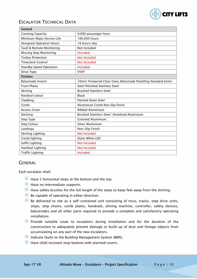
ESCALATOR TECHNICAL DATA
General
Carrying Capacity 9,000 passenger/hour
Minimum Major Service Life 100,000 hours
Designed Operation Hours 18 hours/day
Fault & Remote Monitoring Not Included
Missing Step Monitoring Included
Trolley Protection Not Included
Timeclock Control Not Included
Standby Speed Operation Included
Drive Type VVVF
Finishes
Balustrade Inserts 10mm Tempered Clear Glass Balustrade Panelling Standard Joints
Front Plates Satin Polished Stainless Steel
Skirting Brushed Stainless Steel
Handrail colour Black
Cladding Painted Sheet Steel
Comb Aluminium Comb Non Slip finish
Access Cover Ribbed Aluminium
Decking Brushed Stainless Steel /Anodised Aluminium
Step Type Grooved Aluminium
Step Colour Silver Aluminium
Landings Non-Slip Finish
Skirting Lighting Not Included
Comb lighting Static White LED
Soffit Lighting Not Included
Handrail Lighting Not Included
Traffic Lighting Included
GENERAL
Each escalator shall:
Have 2 horizontal steps at the bottom and the top.
Have no intermediate supports.
Have safety brushes for the full length of the steps to keep feet away from the skirting.
Be capable of operating in either direction.
Be delivered to site as a self-contained unit consisting of truss, tracks, step drive units,
steps, step chains, comb plates, handrails, driving machine, controller, safety devices,
balustrades and all other parts required to provide a complete and satisfactory operating
installation.
Provide suitable cover to escalators during installation and for the duration of the
construction to adequately prevent damage or build up of dust and foreign objects from
accumulating on any part of the new escalators.
Indicate faults to the Building Management System (BMS).
Have child resistant stop buttons with alarmed covers.

Sep-17 V0 Altivate Move – Escalators – Project Specification P a g e | 11
A clear glass fall protection barrier (without mullions) to each side of an escalator where a
passenger could fall. The barrier shall be vertical and extend to at least 1300mm above the
steps.
Be smooth and quiet in operation.
All materials and equipment shall be new. All equipment shall be suitable for the area in which it is
installed and be suitable for a modern building.
TRUSS
The truss shall be of structural steel. It shall be designed for rigidity and to carry the passenger
loads, the mechanism of the escalator, the balustrades and the exterior covering. The upper
section of the truss shall contain the drive machine and the controller. Provide a full - length drip
pan to the underside of the truss.
Provide bearing plates and resilient supports between each end of the truss and the building
structure. Resilient supports shall be selected so that noise, which is transmitted through the
escalator structure is not audible in any occupied areas.
TRACKS
The tracks shall: -
Be constructed of rigid steel sections.
Provide solid support for the step and step chain wheels.
Be aligned to ensure smooth operation of the escalator under all conditions.
Have suitable radius to provide smooth transition from inclined to horizontal movement.
Have a smooth finished track surface.
DRIVE MACHINE
The machine shall: -
Propel the steps smoothly. It shall start and stop without vibration, noise or abrupt
accelerations.
Be an integral gear type. Gear members shall be of steel and special bronze run in oil in an
oil tight housing.
Have dust proof bearings with suitable means for lubrication.
Have an electro mechanical break, to stop the escalator under all normal operating
conditions.
The brake shall stop the escalator gradually. An additional brake shall be provided, mounted
integral with the sprocket drive unit, if chains are used to connect the driving machine to the main
drive shaft. This brake shall stop the escalator gradually if the chain between the driving machine
and main drive shaft breaks.
Sep-17 V0 Altivate Move – Escalators – Project Specification P a g e | 12
STEP CHAINS
The step chains shall: -
Be of the endless roller type located on each side of the steps.
Be made of high grade steel links with hardened pins and rollers designed to accurately
engage the drive sprockets to ensure smooth operation.
Have an automatic tension device at the lower landing to maintain proper chain tension
under varying load conditions.
STEP TREAD AND RISERS
Step treads and risers shall be die-cast aluminium or stainless steel. The treads shall have fine
pitch cleats, which mesh with grooves in the adjoining riser providing a combing action to prevent
material being caught between adjacent steps.
Steps shall have synthetic rollers, which rotate to prevent flat spots. Individual steps shall be
readily removable without disturbing the balustrade or chains. Yellow demarcation strips shall be
provided along both sides of each step tread.
COMBPLATES
At each end of each escalator provide comb plates which: -
Have teeth which mesh with and set into the slots in the tread surface so the points of the
teeth are always below the top of the treads.
Have replaceable sections containing the comb plate teeth.
Have comb plate teeth of non-ductile material which would break before the end of one
tooth was deflected to touch the adjacent straight tooth.
FLOOR PLATES
Provide removable full width floor plates to cover the truss extensions at each end of the
escalators. Floor plates shall have a grooved non - slip surface and shall be of the same material
as the step treads.
Provide tactile warning strips complying with AS1428.4, recessed in the landing plate at the top
and bottom landing.
BALUSTRADES
Provide the escalators with clear safety glass balustrades. The glass panels shall be mounted
vertically without mullions and with the joints at right angles to the handrail.
The interior of the balustrades shall be vertical. Top and bottom landing balustrade newel stands
shall extend beyond the line of the tread way to permit passengers to grasp the handrail and
achieve balance prior to stepping on and off the escalator.

Sep-17 V0 Altivate Move – Escalators – Project Specification P a g e | 13
The balustrade skirting shall:
Be satin finished stainless steel.
Be thick enough to resist bending.
The decking between the skirting and the glazing shall be stainless steel.
HANDRAILS
The handrails shall be reinforced black rubber with smooth vulcanised joints to operate on
specially formed guides and move in synchronism with the steps. Safety guards are to be provided
where the handrails enter and leave the newels. The handrail drive shall be of the traction type
arranged to maintain the handrail at a uniform tension.
MOTORS
Motors shall:
Be suitable for use with escalators.
Have high starting torque and low starting current.
Be protected against overloads, loss of phase and phase reversal.
CONTROLLERS
Provide an enclosed sheet metal control panel in the motor room at the top of each escalator. The
control panel shall include:
A lockable main switch.
A motor over speed monitor to cut off the power and stop the escalator gradually if it over
speeds for any reason.
A non-reversing device to stop the escalator should the direction of travel be accidentally
reversed while the escalator is operating in either direction.
A device to stop the escalator gradually on operation of any safety devices which shall
include:
o skirt switches in case an object is caught between a step and the skirt panel.
o handrail guard switches in case an object is caught at any of the handrails entries.
o chain tension switch in case the tension on either chain is outside the required
range.
o stop buttons.
An interface with the BMS so the escalator controls indicate by closing a volt free contact,
when there is a fault on the escalator or the escalator has been stopped by operation of a
safety device. Provide a variable speed drive for each moving walk interconnected with
passenger sensors.
Escalators shall be set to reduce speed after 60 sec (adjustable 30-600 sec) without
passengers. Sensors shall be interfaced with controls so that escalator is travelling at full
speed when the passenger reaches the first step. Sensors shall be of a type that do not
require posts external to the moving walk.

Sep-17 V0 Altivate Move – Escalators – Project Specification P a g e | 14
SAFETY DEVICES
The escalators shall be equipped, as a minimum, with the following safety devices:
Chain safety contacts to ensure the immediate stopping of the machine in the event
of excessive chain stretch or breakage.
Comb-plate contacts to operate and stop the escalator if the comb-¬plate is moved
from its normal working position when objects are lodged between the treads and
the comb-plate.
Handrail-inlet safety devices at the entry-point of the handrail into the balustrades.
These switches when tripped shall immediately stop the escalator electrically in
order to avoid passenger injury or equipment damage.
Controller phase loss protection.
Emergency stop push buttons with covers and audible alarm located at each end of
the escalator in the balustrade decking and newel.
Maintenance cable sockets in both upper and lower reversing stations.
Means for hand winding of flywheel in order to move the step band manually if
required.
Step running control devices within the step band with five (5) actuation points at
each end of the escalator. System designed to stop the escalator if and when
damage to the steps or to the rollers occurs.
Speed governor for the control of overspeed and/or unintended reversal.
Stop switches as control circuit breakers in both reversing stations.
Protective maintenance guards in reversing stations.
Missing step and broken-step device.
Handrail speed monitoring device which will stop the escalator in the event of
broken or stopped handrail within 15 seconds.
Lighting in upper and lower wells.
Fluorescent step demarcation lights under steps at top and bottom landings.
Skirting micro switches to stop the escalator if a foreign object becomes wedged
between the step and the skirting.
Step up-thrust device at lower landing to stop the escalator if a foreign object
becomes wedged between the riser and tread of adjacent steps.
Step demarcation on skirts to be provided by brush guards to side of escalators.

Sep-17 V0 Altivate Move – Escalators – Project Specification P a g e | 15
KEY OPERATED SWITCHES AND EMERGENCY STOP BUTTONS
Provide emergency stop buttons at the upper and lower landings of each escalator to stop the
escalator upon momentary pressure. The emergency stop buttons shall be protected by an
approved child resistant cover or flap, located on the outside skirting adjacent to the floor, or
other approved position. Moving the cover or flap shall cause a local alarm to sound until the
cover or flap is replaced.
Provide up/down key operated switches at upper and lower landings for starting or reversing the
direction of each escalator.
MATERIALS & FINISHES
All steel used for the truss construction shall be sandblasted and shall receive one coat of
anticorrosive primer. All other steel components and castings shall receive the same protection
against corrosion as the truss construction, unless they are treated by other anticorrosive
measures mentioned separately. Clear anodising of aluminium parts shall be used.
Aluminium: Extrusions per ASTM B221; sheet and plate per ASTM B209.
Cold Roll Steel Sheet: ASTM A366. Structural Steel: ASTM A36. Stainless Steel: AISI, Type 304.
MOVING AND POSITIONING
Make allowance in the tender for council fees, unloading, assembly, moving through site to
relevant location and final positioning of moving walks.
NOISE & VIBRATION
The noise level shall not exceed 60dB(A) one metre from the escalator. Determine the cause and
eliminate any undue noise.
PAINTING & SIGNS
Upon completion of the installation paint to an approved colour, machinery and equipment
installed in the escalator pits.
All steel surfaces shall be effectively rust - proofed. Due care shall be exercised during installation
to prevent damage to surfaces.
Provide a prominent warning notice at each end of each escalator in lettering at least 10mm high:
WARNING
STAND BETWEEN YELLOW LINES
or other signage as required by statutory authorities.

Sep-17 V0 Altivate Move – Escalators – Project Specification P a g e | 16
GUARDS & BARRIERS
Provide transparent soffit guards where escalator passes through a floor and the handrail is within
500mm (horizontally) of the floor opening.
Provide transparent barriers between balustrades at top and bottom of parallel pairs to keep
people out of the space between escalators.
Guards shall be constructed from robust plastic material, ~15mm thick, with rounded corners.
COMMISSIONING & TESTING
GENERAL
Subject all escalator systems to a commissioning and testing procedure before they are put into
service.
Provide all test instruments, other testing facilities and skilled and unskilled labour required to
verify system and equipment performance and to complete all checklist records. Include cost in
tender price. Any work, which does not comply with the specification, shall be made good.
Give at least 2 weeks’ notice prior to the start of the commissioning of any particular system, and
submit a programme of testing and commissioning procedures for that system. Modify the
programme as required.
CHECKLIST
Prepare a detailed and comprehensive checklist prior to commissioning and testing. Two months
prior to the start of commissioning submit the proposed checklist for approval.
The purpose of the checklist is to:
Ensure that all items that should be checked are checked.
Produce a permanent record of the commissioning checks carried out.
Accordingly the checklist must be built up from information contained in this specification, from
suppliers, manufacturers' installation and commissioning data and from experience in
commissioning similar equipment and systems.
The detail of the checklist must be such that it can be completed with a reading or a tick, which
means that every device must be listed e.g. Speed – 0.5 m/s - OK

Sep-17 V0 Altivate Move – Escalators – Project Specification P a g e | 17
The check list for escalators shall cover at least the following:-
Brakes. Load notice.
Drive machine. Step rollers.
Safety switches and devices. Speed control.
Equipment labels. Speed.
Motor room accessories. Safety notices.
Lights. Buttons and switches.
Chains. Timers.
Clearances. Controls.
Pit access devices. Balustrades clean and undamaged.
Steps and tracks clean and free from site damage. Dimensions.
Step demarcation. Finishes.
Tension of step band. Noise.
PROCEDURE
Commissioning and testing procedures shall generally include:
Visual check of all work for completeness, and against diagrams of all wiring.
Check that all work complies with the relevant Regulations.
Check that all equipment is safe to operate, and that overloads, safety devices and
interlocks are all in working order.
Verification of performance under site conditions, under load and simulated "worst case"
condition.
Test continuity and unique identification of all conductors in all cables.
Check main earth connection and test all earth continuity connections.
Check polarity and phase rotation of supply at all outlets.
Check all work for completeness and proper working order.
Test run all equipment for at least 24 hours.
Check calibration and operation of each device.
Final tests shall be conducted in the presence of the consultant.
AUTHORITIES’ INSPECTIONS, FEES & CERTIFICATION
After the commissioning tests have been concluded successfully, arrange for the inspection of the
equipment to Regulatory Authority requirements and issuing of the relevant certificates.
Carry out demonstrations of all systems as required by the authorities. Also allow for all pre-
inspection testing to ensure that all systems are ready for the authorities’ inspection.
Lodge all notices and pay all fees required by the Controlling Authorities, including escalator
registration fees.
The escalator contractor shall make a final check of each escalator operation with the owner or
owner’s representative present prior to turning each escalator over for use. The escalator
contractor shall determine that control systems and operating devices are functioning properly.
Sep-17 V0 Altivate Move – Escalators – Project Specification P a g e | 18
Hand over 3 sets of keys to operate each type of key-operated switch and lock associated with the
escalators. Any keys that over-ride the security system shall be of the restricted broach type that
cannot be copied without written authority from the building owner.
Allow in the Tender Price to pay for any necessary and chargeable testing work.
AS-INSTALLED DRAWINGS & MANUALS
GENERAL
Provide as-installed drawings and manuals on completion of the works and prior to the issue of
the Certificate of Practical Completion.
Submit preliminary copies of the documents for checking.
After approval provide three (3) prints of the drawings full size and one (1) print reduced to A3,
three (3) hard copies of the manual and AutoCAD and PDF files for the drawings on compact disc.
DRAWINGS
The drawings shall be carried out by competent draftsmen.
Workshop drawings prepared and submitted prior to installation shall be amended to show all
variations and will be accepted as as-installed drawings.
The drawings shall also show the following:
The as-installed location of all equipment.
The arrangement of control panels.
Wiring diagrams.
The arrangement of switchboards.
MANUALS
Provide 3 hard copies, and one PDF copy on CD-ROM of each installation manual. The manual
shall include a full description of the installation and functioning of the systems and instructions
for efficient operation and maintenance. The manual shall be bound in a folder with printed label
on the front in the following format:-
INSTALLATION MANUAL FOR ESCALATORS
Escalator Contractor
(as appropriate)
The words "Escalator Manual" and the job name shall be printed along the spine of the folder.

Sep-17 V0 Altivate Move – Escalators – Project Specification P a g e | 19
The manuals shall incorporate the following information grouped into sections.
Index.
Operating instruction for all equipment; include procedures in case of malfunction or civil
emergency.
Manufacturers’ brochure for all equipment.
Schedule of Recommended Maintenance by the building managers.
Schedule of Recommended Maintenance by a Maintenance Contractor (who, for the first 12
months, is the installer).
All relevant information to assist the Proprietor in carrying out the maintenance, additions
and/or alterations to the installation.
Completed checklist (refer Commissioning & Testing).
Where manufacturers' drawings are provided with the manual, they shall be folded and included
within the manual, or alternatively bound separately and cross-referenced in the manual.
WARRANTY & MAINTENANCE
OPERATIONAL WARRANTY MAINTENANCE
(12 MONTHS AFTER PRACTICAL COMPLETION OF HEAD CONTRACT)
The escalator contractor guarantees the materials and workmanship of the apparatus furnished
under these specifications. The escalator contactor shall make good any defects which may
develop within one (1) year from the date of practical completion of the head contract, not due to
ordinary wear and tear, vandalism, improper or insufficient maintenance by others, abuse, misuse,
neglect or any other cause beyond the control of the escalator contractor. Only genuine parts and
supplies as used in the manufacture and installation of the original equipment shall be provided.
This service shall not be subcontracted but shall be performed by the escalator contractor.
During the warranty maintenance period provide qualified and experienced personnel to perform
the maintenance required for safe and reliable operation, including the following:
Make regular service visits at the required intervals and at times agreed with the building
staff, and carry out regular maintenance procedures, including running adjustments,
lubrication and the like.
Promptly attend stoppages or unsatisfactory operation of equipment at any time of the day
or night, and restore the installation to proper working order. Before the start of the
maintenance period, supply the contact telephone numbers of the persons to be called.
Make good faults or damage caused by defects in the installation, and replace defective
parts or parts showing signs of undue wear.
Supply the necessary maintenance materials including lubricants and cleaning materials.
Leave the areas and equipment in and on which maintenance work was performed clean
and tidy after each visit.
Sep-17 V0 Altivate Move – Escalators – Project Specification P a g e | 20
Provide a record of each visit including the date and time, work carried out, name of the
service operator and any relevant, information in one of the following forms:
o a computer record;
o a log book with pages set up for operational maintenance records, neatly bound in
durable vinyl or similar hard covers, permanently labelled with the project name
and date of issue.
At the end of the warranty maintenance period, make a service visit. Test the safety and
protective devices, demonstrate the satisfactory operation of escalator installation, and
certify in writing that it is in satisfactory working order, and is operating correctly.
COMPREHENSIVE MAINTENANCE
Include as a separate item in the tender the annual cost, as at the date of closing of tenders, for
maintaining each escalator in a proper and safe operating condition under a 5, 10 or 20 year
comprehensive maintenance contract commencing after expiry of the operational warranty
maintenance period and in accordance with the following:
Regular inspections, maintenance, adjustments and lubrication of each escalator by a
competent mechanic and assistant, during normal working hours at a mutually agreed
upon time.
Replacement and/or repair all components of the installation necessitated by reason of
normal wear and tear.
Provide all lubricants, compounds and cotton waste.
Promptly answer all calls necessitated by stoppages, or unsatisfactory operation of the
equipment, during and after normal working hour periods, and restore the equipment to
proper working order.
Carry out major replacement or repair work during normal working hours. If otherwise
directed, claims will be received for additional labour costs based on the difference
between afterhours and normal hour rates for the periods worked.