Escalators & moving walks Dr. Gero Gschwendtner EN115-1 Escalators & moving walks EN115-1.
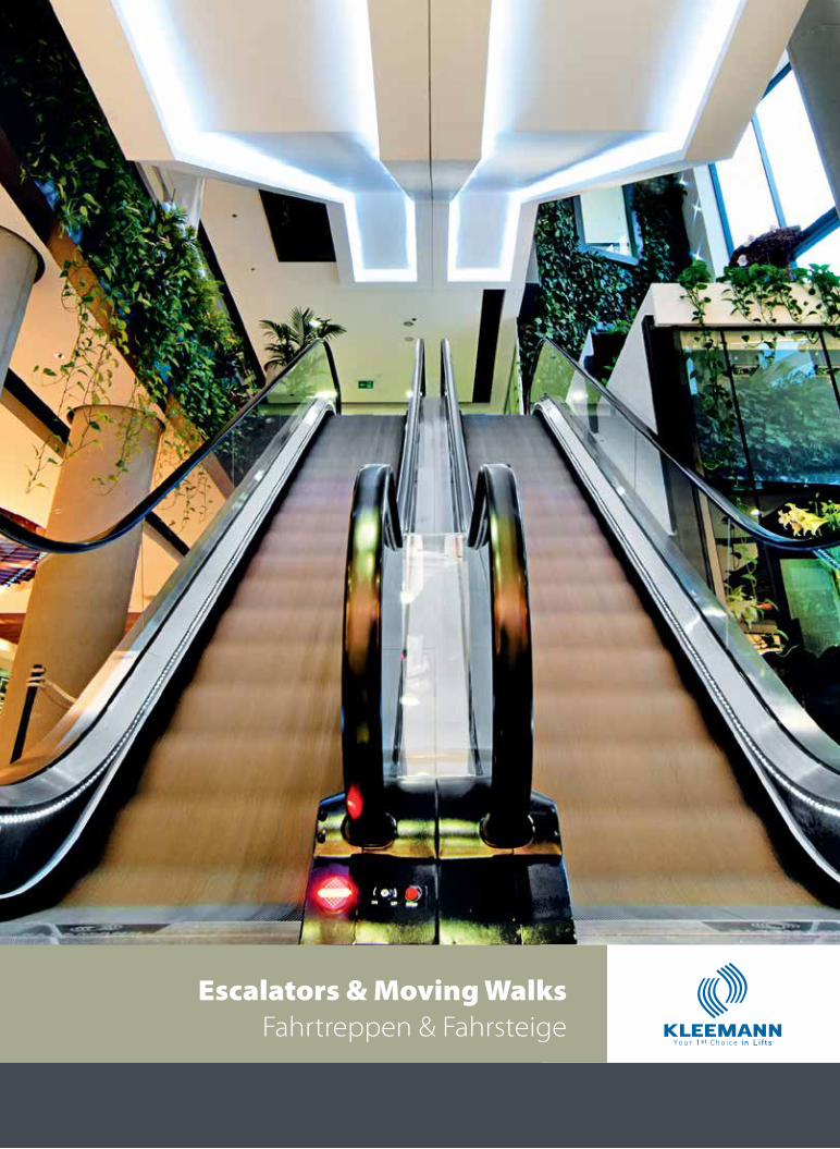
Escalators & Moving Walks Fahrtreppen & Fahrsteige
Escalators & Moving
Walks
Fahrtreppen & Fahrsteige
KLEE
MA
NN
Es
cala
tors
& M
ovin
g W
alks
01
I N D E X I N H A L T
Advantages Vorteile 01
Uses & Features Gebrauch & Ausstattung 02
Special Projects Spezielle Projekte 04
Remote Monitoring System Fernüber Wachungssystem 06
Eco Friendly Umweltschonend 08
Safety Zielwahlsteuerung 10
Design Design 12
Technical Specifications Technische Spezifikationen 14
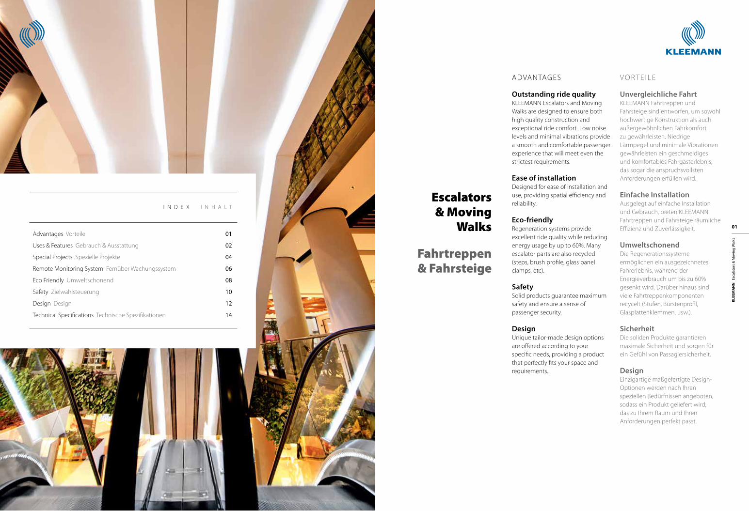
ADVANTAGES
Οutstanding ride qualityKLEEMANN Escalators and Moving Walks are designed to ensure both high quality construction and exceptional ride comfort. Low noise levels and minimal vibrations provide a smooth and comfortable passenger experience that will meet even the strictest requirements.
Ease of installationDesigned for ease of installation and use, providing spatial efficiency and reliability.
Εco-friendlyRegeneration systems provide excellent ride quality while reducing energy usage by up to 60%. Many escalator parts are also recycled (steps, brush profile, glass panel clamps, etc).
SafetySolid products guarantee maximum safety and ensure a sense of passenger security.
DesignUnique tailor-made design options are offered according to your specific needs, providing a product that perfectly fits your space and requirements.
V O R T E I L E
Unvergleichliche FahrtKLEEMANN Fahrtreppen und Fahrsteige sind entworfen, um sowohl hochwertige Konstruktion als auch außergewöhnlichen Fahrkomfort zu gewährleisten. Niedrige Lärmpegel und minimale Vibrationen gewährleisten ein geschmeidiges und komfortables Fahrgasterlebnis, das sogar die anspruchsvollsten Anforderungen erfüllen wird.
Einfache InstallationAusgelegt auf einfache Installation und Gebrauch, bieten KLEEMANN Fahrtreppen und Fahrsteige räumliche Effizienz und Zuverlässigkeit.
Umweltschonend Die Regenerationssysteme ermöglichen ein ausgezeichnetes Fahrerlebnis, während der Energieverbrauch um bis zu 60% gesenkt wird. Darüber hinaus sind viele Fahrtreppenkomponenten recycelt (Stufen, Bürstenprofil, Glasplattenklemmen, usw.).
SicherheitDie soliden Produkte garantieren maximale Sicherheit und sorgen für ein Gefühl von Passagiersicherheit.
DesignEinzigartige maßgefertigte Design-Optionen werden nach Ihren speziellen Bedürfnissen angeboten, sodass ein Produkt geliefert wird, das zu Ihrem Raum und Ihren Anforderungen perfekt passt.
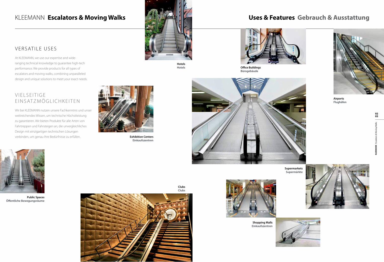
SupermarketsSupermärkte
Exhibition CentersEinkaufszentren
AirportsFlughäfen
Shopping MallsEinkaufszentren
KLEEMANN Escalators & Moving Walks Uses & Features Gebrauch & Ausstattung
V E R S AT I L Ε U S E S
At KLEEMANN, we use our expertise and wide-
ranging technical knowledge to guarantee high-tech
performance. We provide products for all types of
escalators and moving walks, combining unparalleled
design and unique solutions to meet your exact needs.
V I E L S E I T I G E E I N S AT Z M Ö G L I C H K E I T E N
Wir bei KLEEMANN nutzen unsere Fachkenntnis und unser
weitreichendes Wissen, um technische Höchstleistung
zu garantieren. Wir bieten Produkte für alle Arten von
Fahrtreppen und Fahrsteigen an, die unvergleichliches
Design mit einzigartigen technischen Lösungen
verbinden, um genau Ihre Bedürfnisse zu erfüllen.
Office BuildingsBürogebäude
ClubsClubs
HotelsHotels
Public SpacesÖffentliche Bewegungsräume
KLEE
MA
NN
Es
cala
tors
& M
ovin
g W
alks
02 03
KLEEMANN Special Projects Spezielle Projekte
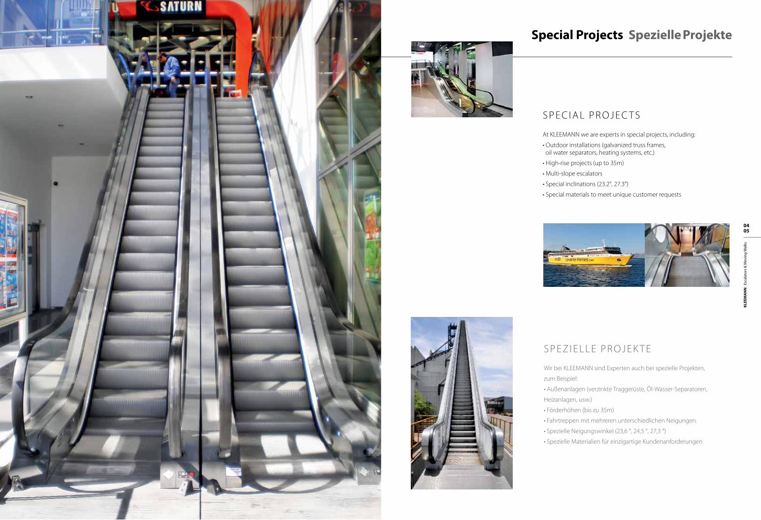
S P E C I A L P R O J E C T S
At KLEEMANN we are experts in special projects, including:
• Outdoor installations (galvanized truss frames, oil water separators, heating systems, etc.)
• High-rise projects (up to 35m)
• Multi-slope escalators
• Special inclinations (23.2°, 27.3°)
• Special materials to meet unique customer requests
S P E Z I E L L E P R O J E K T E
Wir bei KLEEMANN sind Experten auch bei spezielle Projekten,
zum Beispiel:
• Außenanlagen (verzinkte Traggerüste, Öl-Wasser-Separatoren,
Heizanlagen, usw.)
• Förderhöhen (bis zu 35m)
• Fahrtreppen mit mehreren unterschiedlichen Neigungen.
• Spezielle Neigungswinkel (23,6 °, 24,5 °, 27,3 °)
• Spezielle Materialien für einzigartige Kundenanforderungen
KLEE
MA
NN
Es
cala
tors
& M
ovin
g W
alks
04 05
KLEE
MA
NN
Es
cala
tors
& M
ovin
g W
alks
06 07
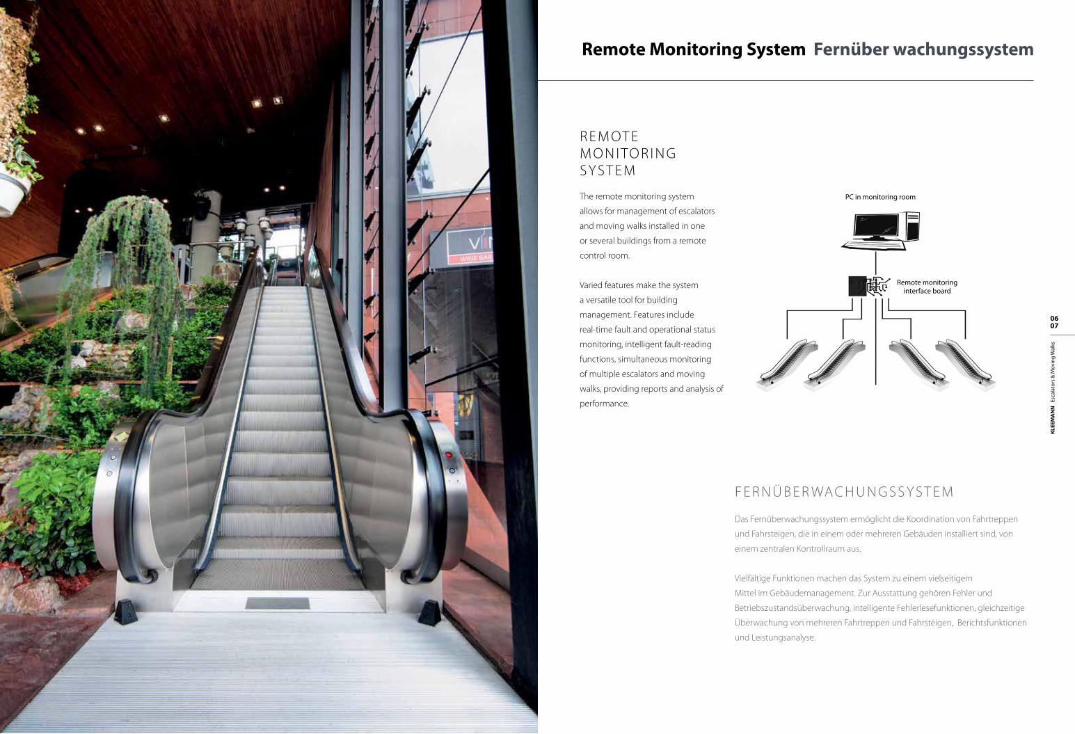
R E M OT E M O N I TO R I N G S Y S T E M
The remote monitoring system
allows for management of escalators
and moving walks installed in one
or several buildings from a remote
control room.
Varied features make the system
a versatile tool for building
management. Features include
real-time fault and operational status
monitoring, intelligent fault-reading
functions, simultaneous monitoring
of multiple escalators and moving
walks, providing reports and analysis of
performance.
KLEEMANN Escalators & Moving Walks Remote Monitoring System Fernüber wachungssystem
F E R N Ü B E R WA C H U N G S S Y S T E M
Das Fernüberwachungssystem ermöglicht die Koordination von Fahrtreppen
und Fahrsteigen, die in einem oder mehreren Gebäuden installiert sind, von
einem zentralen Kontrollraum aus.
Vielfältige Funktionen machen das System zu einem vielseitigem
Mittel im Gebäudemanagement. Zur Ausstattung gehören Fehler und
Betriebszustandsüberwachung, intelligente Fehlerlesefunktionen, gleichzeitige
Überwachung von mehreren Fahrtreppen und Fahrsteigen, Berichtsfunktionen
und Leistungsanalyse.
PC in monitoring room
Remote monitoring interface board
KLEE
MA
NN
Es
cala
tors
& M
ovin
g W
alks
08 09
KLEEMANN Escalators & Moving Walks Eco Friendly Umweltschonend
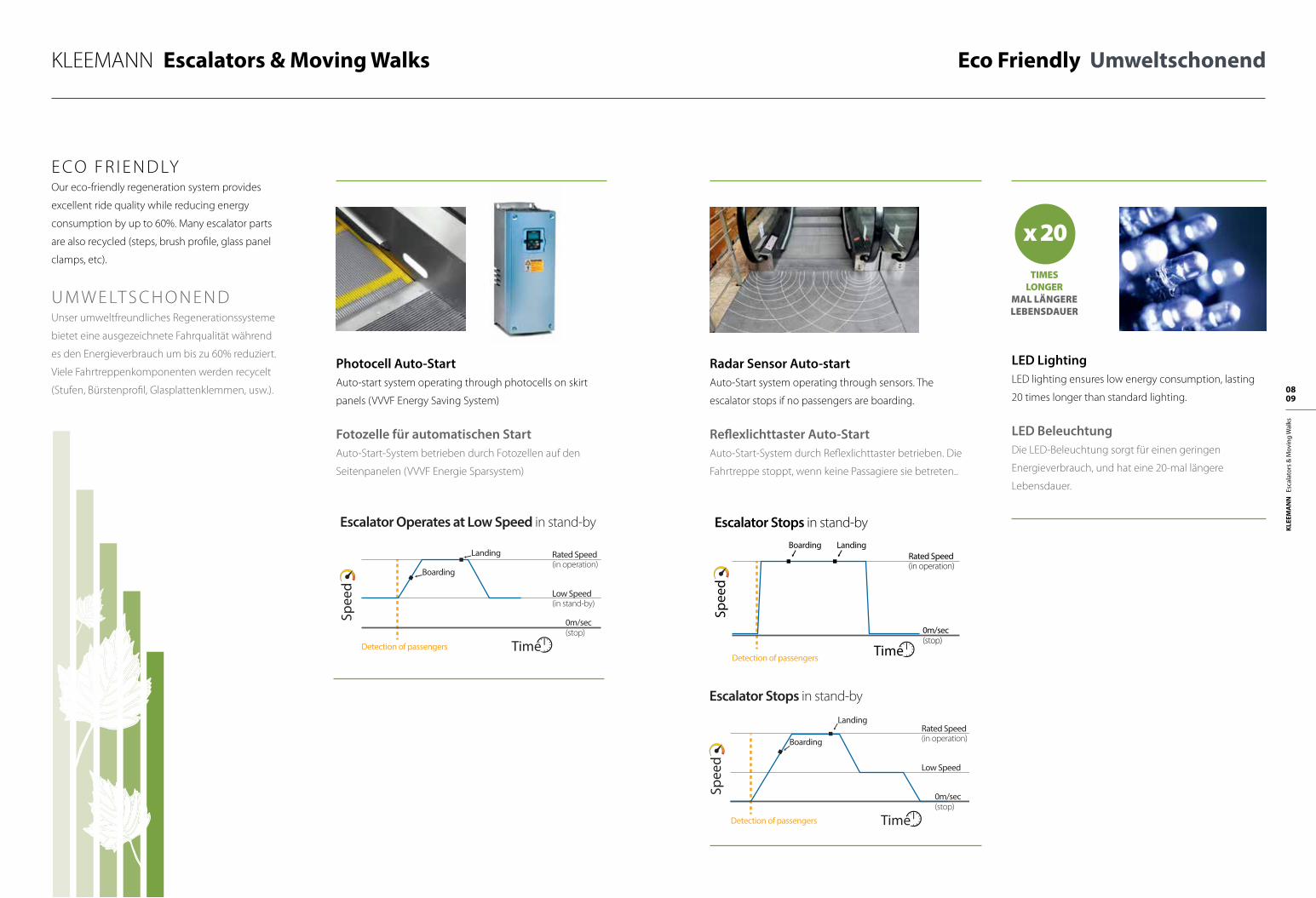
E CO F R I E N D LYOur eco-friendly regeneration system provides
excellent ride quality while reducing energy
consumption by up to 60%. Many escalator parts
are also recycled (steps, brush profile, glass panel
clamps, etc).
U M W E LT S C H O N E N DUnser umweltfreundliches Regenerationssysteme
bietet eine ausgezeichnete Fahrqualität während
es den Energieverbrauch um bis zu 60% reduziert.
Viele Fahrtreppenkomponenten werden recycelt
(Stufen, Bürstenprofil, Glasplattenklemmen, usw.).
Radar Sensor Auto-startAuto-Start system operating through sensors. The
escalator stops if no passengers are boarding.
Reflexlichttaster Auto-StartAuto-Start-System durch Reflexlichttaster betrieben. Die
Fahrtreppe stoppt, wenn keine Passagiere sie betreten..
Photocell Auto-StartAuto-start system operating through photocells on skirt
panels (VVVF Energy Saving System)
Fotozelle für automatischen StartAuto-Start-System betrieben durch Fotozellen auf den
Seitenpanelen (VVVF Energie Sparsystem)
LED Lighting LED lighting ensures low energy consumption, lasting
20 times longer than standard lighting.
LED BeleuchtungDie LED-Beleuchtung sorgt für einen geringen
Energieverbrauch, und hat eine 20-mal längere
Lebensdauer.
TIMESLONGER
MAL LÄNGERELEBENSDAUER
x 20
Spee
d
Escalator Operates at Low Speed in stand-by
Boarding
Landing Rated Speed(in operation)
Low Speed(in stand-by)
0m/sec(stop)
Detection of passengers Time
Spee
d
Escalator Stops in stand-by
Boarding LandingRated Speed(in operation)
0m/sec(stop)
Detection of passengers Time
Spee
dEscalator Stops in stand-by
Boarding
LandingRated Speed(in operation)
Low Speed
0m/sec(stop)
Detection of passengers Time
KLEE
MA
NN
Es
cala
tors
& M
ovin
g W
alks
10 11
KLEEMANN Escalators & Moving Walks Safety Sicherheit
H I G H P E R F O R MA N C E – O P E R AT I O N H O C H L E I S T U N G – B E T R I E B
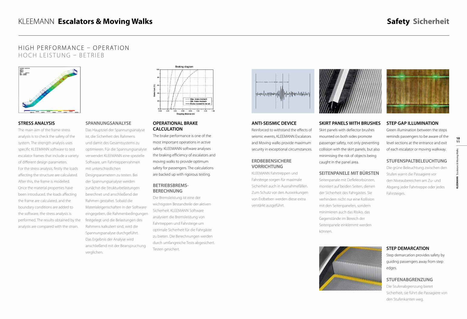
STRESS ANALYSISThe main aim of the frame stress
analysis is to check the safety of the
system. The strength analysis uses
specific KLEEMANN software to test
escalator frames that include a variety
of different design parameters.
For the stress analysis, firstly the loads
affecting the structure are calculated.
After this, the frame is modelled.
Once the material properties have
been introduced, the loads affecting
the frame are calculated, and the
boundary conditions are added to
the software, the stress analysis is
performed. The results obtained by the
analysis are compared with the strain.
OPERATIONAL BRAKE CALCULATION The brake performance is one of the
most important operations in active
safety. KLEEMANN software analyses
the braking efficiency of escalators and
moving walks to provide optimum
safety for passengers. The calculations
are backed up with rigorous testing.
BETRIEBSBREMS-BERECHNUNG
Die Bremsleistung ist eine der
wichtigsten Bestandteile der aktiven
Sicherheit. KLEEMANN Software
analysiert die Bremsleistung von
Fahrtreppen und Fahrsteige um
optimale Sicherheit für die Fahrgäste
zu bieten. Die Berechnungen werden
durch umfangreiche Tests abgesichert.
Testen gesichert.
ANTI-SEISMIC DEVICEReinforced to withstand the effects of
seismic events, KLEEMANN Escalators
and Moving walks provide maximum
security in exceptional circumstances.
ERDBEBENSICHERE VORRICHTUNGKLEEMANN Fahrtreppen und
Fahrsteige sorgen für maximale
Sicherheit auch in Ausnahmefällen.
Zum Schutz vor den Auswirkungen
von Erdbeben werden diese extra
verstärkt ausgeführt.
SKIRT PANELS WITH BRUSHESSkirt panels with deflector brushes
mounted on both sides promote
passenger safety, not only preventing
collision with the skirt panels, but also
minimising the risk of objects being
caught in the panel area.
SEITENPANELE MIT BÜRSTENSeitenpanale mit Deflektorbürsten,
montiert auf beiden Seiten, dienen
der Sicherheit des Fahrgastes. Sie
verhindern nicht nur eine Kollision
mit den Seitenpanelen, sondern
minimieren auch das Risiko, das
Gegenstände im Bereich der
Seitenpanele einklemmt werden
können.
STEP GAP ILLUMINATIONGreen illumination between the steps
reminds passengers to be aware of the
level sections at the entrance and exit
of each escalator or moving walkway.
STUFENSPALTBELEUCHTUNGDie grüne Beleuchtung zwischen den
Stufen warnt die Passagiere vor
den Niveaubereichen am Zu- und
Abgang jeder Fahrtreppe oder jedes
Fahrsteiges.
STEP DEMARCATIONStep demarcation provides safety by
guiding passengers away from step
edges.
STUFENABGRENZUNG
Die Stufenabgrenzung bietet
Sicherheit, sie führt die Passagiere von
den Stufenkanten weg.
SPANNUNGSANALYSEDas Hauptziel der Spannungsanalyse
ist, die Sicherheit des Rahmens
und damit des Gesamtsystems zu
optimieren. Für die Spannungsanalyse
verwendet KLEEMANN eine spezielle
Software, um Fahrtreppenrahmen
mit unterschiedlichen
Designparametern zu testen. Bei
der Spannungsanalyse werden
zunächst die Strukturbelastungen
berechnet und anschließend der
Rahmen gestaltet. Sobald die
Materialeigenschaften in der Software
eingegeben, die Rahmenbedingungen
festgelegt und die Belastungen des
Rahmens kalkuliert sind, wird die
Spannungsanalyse durchgeführt.
Das Ergebnis der Analyse wird
anschließend mit der Beanspruchung
verglichen.
KLEE
MA
NN
Es
cala
tors
& M
ovin
g W
alks
12 13
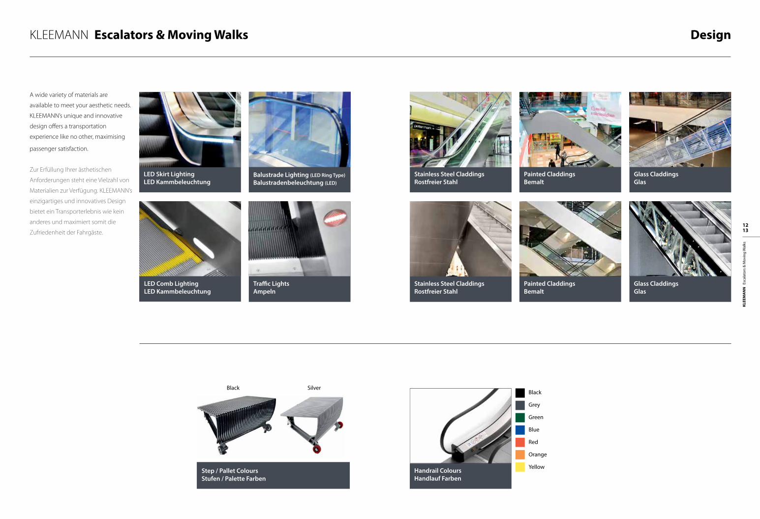
KLEEMANN Escalators & Moving Walks Design
LED Skirt Lighting LED Kammbeleuchtung
Stainless Steel CladdingsRostfreier Stahl
Stainless Steel CladdingsRostfreier Stahl
Traffic LightsAmpeln
Painted CladdingsBemalt
Painted CladdingsBemalt
Handrail ColoursHandlauf Farben
Glass CladdingsGlas
Glass CladdingsGlas
LED Comb LightingLED Kammbeleuchtung
Balustrade Lighting (LED Ring Type) Balustradenbeleuchtung (LED)
A wide variety of materials are
available to meet your aesthetic needs.
KLEEMANN’s unique and innovative
design offers a transportation
experience like no other, maximising
passenger satisfaction.
Zur Erfüllung Ihrer ästhetischen
Anforderungen steht eine Vielzahl von
Materialien zur Verfügung. KLEEMANN’s
einzigartiges und innovatives Design
bietet ein Transporterlebnis wie kein
anderes und maximiert somit die
Zufriedenheit der Fahrgäste.
Step / Pallet ColoursStufen / Palette Farben
Black SilverBlack
Grey
Green
Blue
Red
Orange
Yellow
KLEE
MA
NN
Es
cala
tors
& M
ovin
g W
alks
14 15
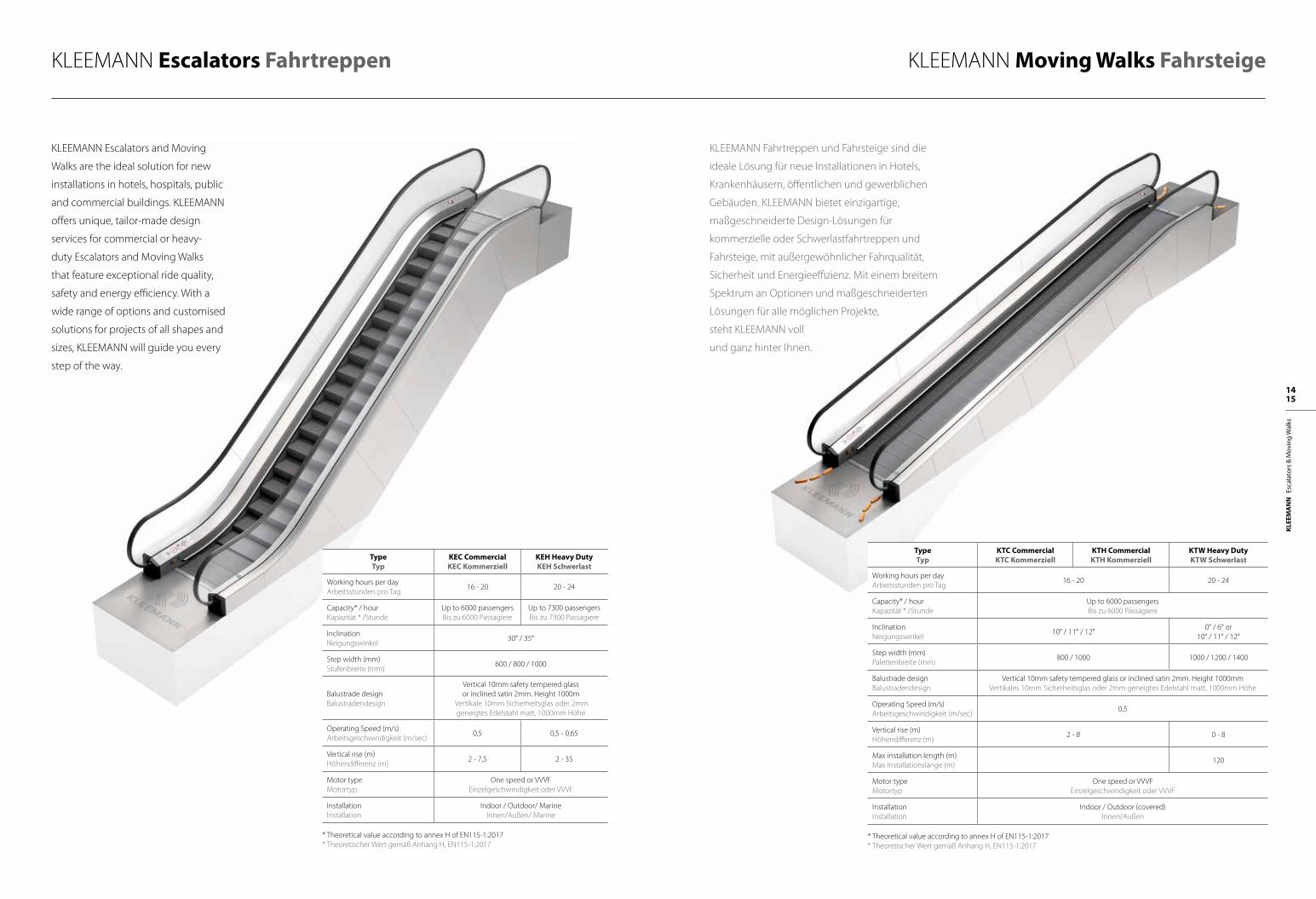
KLEEMANN Escalators Fahrtreppen KLEEMANN Moving Walks Fahrsteige
TypeΤyp
KEC CommercialKEC Kommerziell
KEH Heavy DutyKEH Schwerlast
Working hours per dayArbeitsstunden pro Tag
16 - 20 20 - 24
Capacity* / hourKapazität * /Stunde
Up to 6000 passengersBis zu 6000 Passagiere
Up to 7300 passengersBis zu 7300 Passagiere
InclinationNeigungswinkel
30° / 35°
Step width (mm)Stufenbreite (mm)
600 / 800 / 1000
Balustrade designBalustradendesign
Vertical 10mm safety tempered glassor inclined satin 2mm. Height 1000m
Vertikale 10mm Sicherheitsglas oder 2mmgeneigtes Edelstahl matt, 1000mm Höhe
Operating Speed (m/s)Arbeitsgeschwindigkeit (m/sec)
0,5 0,5 - 0,65
Vertical rise (m)Höhendifferenz (m)
2 - 7,5 2 - 35
Motor type Motortyp
One speed or VVVFEinzelgeschwindigkeit oder VVVF
InstallationInstallation
Indoor / Outdoor/ MarineInnen/Außen/ Marine
* Theoretical value according to annex H of EN115-1:2017* Theoretischer Wert gemäß Anhang H, EN115-1:2017
TypeΤyp
KTC CommercialKTC Kommerziell
KTH CommercialKTH Kommerziell
KTW Heavy DutyKTW Schwerlast
Working hours per dayArbeitsstunden pro Tag
16 - 20 20 - 24
Capacity* / hourKapazität * /Stunde
Up to 6000 passengersBis zu 6000 Passagiere
InclinationNeigungswinkel
10° / 11° / 12°0° / 6° or
10° / 11° / 12°
Step width (mm)Palettenbreite (mm)
800 / 1000 1000 / 1200 / 1400
Balustrade designBalustradendesign
Vertical 10mm safety tempered glass or inclined satin 2mm. Height 1000mmVertikales 10mm Sicherheitsglas oder 2mm geneigtes Edelstahl matt, 1000mm Höhe
Operating Speed (m/s)Arbeitsgeschwindigkeit (m/sec)
0,5
Vertical rise (m)Höhendifferenz (m)
2 - 8 0 - 8
Max installation length (m)Max Installationslänge (m)
120
Motor type Motortyp
One speed or VVVFEinzelgeschwindigkeit oder VVVF
InstallationInstallation
Indoor / Outdoor (covered)Innen/Außen
* Theoretical value according to annex H of EN115-1:2017* Theoretischer Wert gemäß Anhang H, EN115-1:2017
KLEEMANN Escalators and Moving
Walks are the ideal solution for new
installations in hotels, hospitals, public
and commercial buildings. KLEEMANN
offers unique, tailor-made design
services for commercial or heavy-
duty Escalators and Moving Walks
that feature exceptional ride quality,
safety and energy efficiency. With a
wide range of options and customised
solutions for projects of all shapes and
sizes, KLEEMANN will guide you every
step of the way.
KLEEMANN Fahrtreppen und Fahrsteige sind die
ideale Lösung für neue Installationen in Hotels,
Krankenhäusern, öffentlichen und gewerblichen
Gebäuden. KLEEMANN bietet einzigartige,
maßgeschneiderte Design-Lösungen für
kommerzielle oder Schwerlastfahrtreppen und
Fahrsteige, mit außergewöhnlicher Fahrqualität,
Sicherheit und Energieeffizienz. Mit einem breitem
Spektrum an Optionen und maßgeschneiderten
Lösungen für alle möglichen Projekte,
steht KLEEMANN voll
und ganz hinter Ihnen.
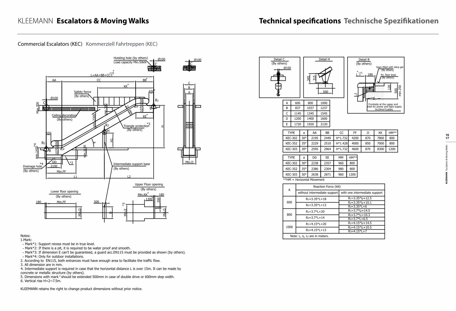
KLEEMANN Escalators & Moving Walks Technical specifications Technische Spezifikationen
KLEE
MA
NN
Es
cala
tors
& M
ovin
g W
alks
16 17
C
B
650
B
650
W.P
W.P
AA CC BB
KK
L=AA+BB+CC
EE
1000
1070
1000
1070
min
.113
0
Min.FF
DD
JJM
M
min
.300
L1 L2
Ø100m
in.2
300
R2
R3
R1
H
Ø100
500
D
a
C
H1
min
.143
0
2100
L +15 0
Max
.700 C
H
+15 0
Min.FF180
Min
.D
Min
.D
200
Min
.E
1300Min.KK
*3
180**
*
**
*
*
*2
*3
ABC
Ø100
Min.D
1000800600A
1920
1400
1345
1037
1200D
E 1720
B
C
837
1145
1600
2120
1237
1545
Load capacity Min.50kNHoisting hole (by others)
Safety fence(By others)
Triangle protection (By others)
Intermediate support base(By others)
(By others)
Lower floor opening (By others)
Upper Floor opening
Ceiling decoration(By others)
Drainage hole
*4
*4
(By others)
A
1000
800
600
Reaction Force (kN)
without intermediate support with one intermediate support
Note: L, L1, L2 are in meters.
R2=4.15*L+13
R1=4.15*L+20
R1=3.7*L+20
R2=3.7*L+14
R2=3.35*L+13
R1=3.35*L+18 R1=3.35*L2+12.5R2=3.35*L1+10.1R3=3.35*L+6R1=3.7*L2+14.5R2=3.7*L1+10.3R3=3.7*L+6.5R1=4.15*L2+14.5R2=4.15*L1+10.5R3=4.15*L+7
*1
120
500
180
min
.250
Detail B(By others)
fin. floor level
(By others)Gaps filled with silica gel
(By others)
Frontside at the upper end
5x10mm (cable)inlet for power and light supply
315
345
500
Detail HDetail C
Ø100
50kN
*
(By others)
2449
KEC-352
KEC-302
35°
30° 2195
TYPE a BBAA
7800
KK
H*1.732 4200 870
CC FF JJ
KEC-303 30° 29642595 8300H*1.732 4600 870
25102229 7000H*1.428 8504000
35°
30°
TYPE a
23572238
EEDD
960
MM
30° 28712638 960
23042386 980KEC-352
KEC-302
KEC-303
800
800
1200
HM**
800
800
1200
HM**
**HM = Horizontal Movement
2
Notes:1.Mark: • Mark*1: Support recess must be in true level. • Mark*2: If there is a pit, it is required to be water proof and smooth. • Mark*3: If dimension E can't be guaranteed, a guard acc.EN115 must be provided as shown (by others). • Mark*4: Only for outdoor installations.2. According to EN115, both entrances must have enough area to facilitate the traffic flow.3. All dimension are in mm.4. Intermediate support is required in case that the horizontal distance L is over 15m. It can be made by concrete or metallic structure (by others).5. Dimensions with mark * should be extended 500mm in case of double drive or 600mm step width.6. Vertical rise H=2~7.5m.
KLEEMANN retains the right to change product dimensions without prior notice.
F
E
D
C
B
A
1 2 3 4 5 6 7
B
A
8
F
E
D
C
1 2 3 4 5 6 7 8
C
B
650
B
650
W.P
W.P
AA CC BB
KK
L=AA+BB+CC
EE
1000
1070
1000
1070
min
.113
0
Min.FF
DD
JJM
M
min
.300
L1 L2
Ø100
min
.230
0
R2
R3
R1
H
Ø100
500
D
a
C
H1
min
.143
0
2100
L +15 0
Max
.700 C
H
+15 0
Min.FF180
Min
.D
Min
.D
200
Min
.E
1300Min.KK
*3
180**
*
**
*
*
*2
*3
ABC
Ø100
Min.D
1000800600A
1920
1400
1345
1037
1200D
E 1720
B
C
837
1145
1600
2120
1237
1545
Load capacity Min.50kNHoisting hole (by others)
Safety fence(By others)
Triangle protection (By others)
Intermediate support base(By others)
(By others)
Lower floor opening (By others)
Upper Floor opening
Ceiling decoration(By others)
Drainage hole
*4
*4
(By others)
A
1000
800
600
Reaction Force (kN)
without intermediate support with one intermediate support
Note: L, L1, L2 are in meters.
R2=4.15*L+13
R1=4.15*L+20
R1=3.7*L+20
R2=3.7*L+14
R2=3.35*L+13
R1=3.35*L+18 R1=3.35*L2+12.5R2=3.35*L1+10.1R3=3.35*L+6R1=3.7*L2+14.5R2=3.7*L1+10.3R3=3.7*L+6.5R1=4.15*L2+14.5R2=4.15*L1+10.5R3=4.15*L+7
*1
120
500
180
min
.250
Detail B(By others)
fin. floor level
(By others)Gaps filled with silica gel
(By others)
Frontside at the upper end
5x10mm (cable)inlet for power and light supply
315
345
500
Detail HDetail C
Ø100
50kN
*
(By others)
2449
KEC-352
KEC-302
35°
30° 2195
TYPE a BBAA
7800
KK
H*1.732 4200 870
CC FF JJ
KEC-303 30° 29642595 8300H*1.732 4600 870
25102229 7000H*1.428 8504000
35°
30°
TYPE a
23572238
EEDD
960
MM
30° 28712638 960
23042386 980KEC-352
KEC-302
KEC-303
800
800
1200
HM**
800
800
1200
HM**
**HM = Horizontal Movement
2
Notes:1.Mark: • Mark*1: Support recess must be in true level. • Mark*2: If there is a pit, it is required to be water proof and smooth. • Mark*3: If dimension E can't be guaranteed, a guard acc.EN115 must be provided as shown (by others). • Mark*4: Only for outdoor installations.2. According to EN115, both entrances must have enough area to facilitate the traffic flow.3. All dimension are in mm.4. Intermediate support is required in case that the horizontal distance L is over 15m. It can be made by concrete or metallic structure (by others).5. Dimensions with mark * should be extended 500mm in case of double drive or 600mm step width.6. Vertical rise H=2~7.5m.
KLEEMANN retains the right to change product dimensions without prior notice.
F
E
D
C
B
A
1 2 3 4 5 6 7
B
A
8
F
E
D
C
1 2 3 4 5 6 7 8
Commercial Escalators (KEC) Kommerziell Fahrtreppen (KEC)
C
B
650
B
650
W.P
W.P
AA CC BB
KK
L=AA+BB+CC
EE
1000
1070
1000
1070
min
.113
0
Min.FF
DD
JJM
M
min
.300
L1 L2
Ø100
min
.230
0
R2
R3
R1
H
Ø100
500
D
a
C
H1
min
.143
0
2100
L +15 0
Max
.700 C
H
+15 0
Min.FF180
Min
.D
Min
.D
200
Min
.E
1300Min.KK
*3
180**
*
**
*
*
*2
*3
ABC
Ø100
Min.D
1000800600A
1920
1400
1345
1037
1200D
E 1720
B
C
837
1145
1600
2120
1237
1545
Load capacity Min.50kNHoisting hole (by others)
Safety fence(By others)
Triangle protection (By others)
Intermediate support base(By others)
(By others)
Lower floor opening (By others)
Upper Floor opening
Ceiling decoration(By others)
Drainage hole
*4
*4
(By others)
A
1000
800
600
Reaction Force (kN)
without intermediate support with one intermediate support
Note: L, L1, L2 are in meters.
R2=4.15*L+13
R1=4.15*L+20
R1=3.7*L+20
R2=3.7*L+14
R2=3.35*L+13
R1=3.35*L+18 R1=3.35*L2+12.5R2=3.35*L1+10.1R3=3.35*L+6R1=3.7*L2+14.5R2=3.7*L1+10.3R3=3.7*L+6.5R1=4.15*L2+14.5R2=4.15*L1+10.5R3=4.15*L+7
*1
120
500
180
min
.250
Detail B(By others)
fin. floor level
(By others)Gaps filled with silica gel
(By others)
Frontside at the upper end
5x10mm (cable)inlet for power and light supply
315
345
500
Detail HDetail C
Ø100
50kN
*
(By others)
2449
KEC-352
KEC-302
35°
30° 2195
TYPE a BBAA
7800
KK
H*1.732 4200 870
CC FF JJ
KEC-303 30° 29642595 8300H*1.732 4600 870
25102229 7000H*1.428 8504000
35°
30°
TYPE a
23572238
EEDD
960
MM
30° 28712638 960
23042386 980KEC-352
KEC-302
KEC-303
800
800
1200
HM**
800
800
1200
HM**
**HM = Horizontal Movement
2
Notes:1.Mark: • Mark*1: Support recess must be in true level. • Mark*2: If there is a pit, it is required to be water proof and smooth. • Mark*3: If dimension E can't be guaranteed, a guard acc.EN115 must be provided as shown (by others). • Mark*4: Only for outdoor installations.2. According to EN115, both entrances must have enough area to facilitate the traffic flow.3. All dimension are in mm.4. Intermediate support is required in case that the horizontal distance L is over 15m. It can be made by concrete or metallic structure (by others).5. Dimensions with mark * should be extended 500mm in case of double drive or 600mm step width.6. Vertical rise H=2~7.5m.
KLEEMANN retains the right to change product dimensions without prior notice.
F
E
D
C
B
A
1 2 3 4 5 6 7
B
A
8
F
E
D
C
1 2 3 4 5 6 7 8
KLEEMANN Escalators & Moving Walks
KLEE
MA
NN
Es
cala
tors
& M
ovin
g W
alks
18 19
W.P
W.P
Min
.230
0
500
D
a
KEH302
Type
KEH352
KEH303
KEH353
KEH303
35°
30°
a
35°
30°
30°
BBAA
H*1.428
H*1.732
CC DD
H*1.428
H*1.732
H*1.732
KKEE FF JJ MMUpper radius
1500
1500
1500
1500
2700
Min.D
ABC
Ø120C
KEH304 30° H*1.7321500
KEH304 30° H*1.7322700
2231 2598
2631 2998
3031 3398
2266 2682
2666 3082
2863 3283
3263 3683
2370 2815
2770 3215
3170 3615
2505 2780
2905 3180
3000 3500
3400 3900
4530 870
4930 870
4420 850
4820 850
5330 870
5160 870
5560 870
1060 8000
1060 8400
1060 8800
1080 7200
1080 7600
1060 8800
1060 9220
Reaction Force (kN)A
R2=4.95*L+10.5
R1=4.95*L+19.5
R1=4.45*L+17
R2=4.45*L+9.5
R2=4.05*L+8.5
R1=4.05*L+16.3
1000
800
600
Note: 1. L, L1 and L2 are in meters. 2. L1 and L2 do not exceed 15m.
without intermediate support with one intermediate support
R1=4.05*L2+14
R2=4.05*L1+7
R3=4.2*L+10
R1=4.45*L2+16
R2=4.45*L1+7.5
R3=4.7*L+11
R1=4.95*L2+17.2
R2=4.95*L1+8.3
R3=5.2*L+11.3
1000800600A
1990
1470
1395
1110
1270D
E 1790
B
C
910
1195
1670
2190
1310
1595
Vertical Balustrade
Inclined Balustrade
1000800600A
1990
1470
1395
1037
1270D
E 1790
B
C
837
1195
1670
2190
1237
1595
B
BBMin.KK
CC
Min
.300
C
L=AA+BB+CC +15 0
Ø120
Triangle protection
H
R2
B
680
2
Ceiling decoration(by others)
(by others)
EE
Load capacity Min.80kNHoisting hole (By others)
Safety fence(by others)
680
R1
CØ120
H1
Min
.155
0
Min
.12
50
DDMin.FF
L2L1
R3
(By others)
AA
Intermediate support base(By others)
(By others)
Min.FF
Lower floor opening
180
Min
.D
Min
.D20
0
Min
.E
(By others)
1300Min.KK
*3
180
Upper floor opening
*
500
135
L +15 0 fin. floor level
Frontside at the upper end
5x10mm (cable)inlet for power and light supply
Detail B(By others)
180
*1
*3
(By others)
**
*
*
*
**
Drainage hole
(By others)Gaps filled with silica gel
*4
315
345
500
Detail H
*4
Detail C
Ø120
80kN
HM**
800
1200
1600
1200
1600
800
1200
**HM = Horizontal Movement
H
min
.250
*4
2
F
E
D
C
B
A
1 2 3 4 5 6 7
B
A
8
F
E
D
C
1 2 3 4 5 6 7 8
1000
1235
1000
1120
JJM
M
2100
Notes:1.Mark: • Mark*1: Supports need to be in true level. • Mark*2: If there is pit, pit need to be water proof and smooth. • Mark*3: If dimension E can't be guaranteed, a guard acc.EN115 must be provided as shown(by others). • Mark*4: Only for outdoor installations.2. According to EN115, the entrance of bothing landing must have enough area to facilitate the traffic flow.3. All dimension refer to finished dimension is in mm.4. Intermediate support is required in case of horizontal distance L over 15m. It can be made by concrete or metallic structure (By others).5. Dimensions with mark * should be extended 500mm in case 600mm step or double drive or 500mm in case VVVF drive.6. Vertical rise 2m~12m.
W.P
W.P
Min
.230
0
500
D
a
KEH302
Type
KEH352
KEH303
KEH353
KEH303
35°
30°
a
35°
30°
30°
BBAA
H*1.428
H*1.732
CC DD
H*1.428
H*1.732
H*1.732
KKEE FF JJ MMUpper radius
1500
1500
1500
1500
2700
Min.D
ABC
Ø120C
KEH304 30° H*1.7321500
KEH304 30° H*1.7322700
2231 2598
2631 2998
3031 3398
2266 2682
2666 3082
2863 3283
3263 3683
2370 2815
2770 3215
3170 3615
2505 2780
2905 3180
3000 3500
3400 3900
4530 870
4930 870
4420 850
4820 850
5330 870
5160 870
5560 870
1060 8000
1060 8400
1060 8800
1080 7200
1080 7600
1060 8800
1060 9220
Reaction Force (kN)A
R2=4.95*L+10.5
R1=4.95*L+19.5
R1=4.45*L+17
R2=4.45*L+9.5
R2=4.05*L+8.5
R1=4.05*L+16.3
1000
800
600
Note: 1. L, L1 and L2 are in meters. 2. L1 and L2 do not exceed 15m.
without intermediate support with one intermediate support
R1=4.05*L2+14
R2=4.05*L1+7
R3=4.2*L+10
R1=4.45*L2+16
R2=4.45*L1+7.5
R3=4.7*L+11
R1=4.95*L2+17.2
R2=4.95*L1+8.3
R3=5.2*L+11.3
1000800600A
1990
1470
1395
1110
1270D
E 1790
B
C
910
1195
1670
2190
1310
1595
Vertical Balustrade
Inclined Balustrade
1000800600A
1990
1470
1395
1037
1270D
E 1790
B
C
837
1195
1670
2190
1237
1595
B
BBMin.KK
CC
Min
.300
C
L=AA+BB+CC +15 0
Ø120
Triangle protection
H
R2
B
680
2
Ceiling decoration(by others)
(by others)
EE
Load capacity Min.80kNHoisting hole (By others)
Safety fence(by others)
680
R1
CØ120
H1
Min
.155
0
Min
.12
50
DDMin.FF
L2L1
R3
(By others)
AA
Intermediate support base(By others)
(By others)
Min.FF
Lower floor opening
180
Min
.D
Min
.D20
0
Min
.E
(By others)
1300Min.KK
*3
180
Upper floor opening
*
500
135
L +15 0 fin. floor level
Frontside at the upper end
5x10mm (cable)inlet for power and light supply
Detail B(By others)
180
*1
*3
(By others)
**
*
*
*
**
Drainage hole
(By others)Gaps filled with silica gel
*4
315
345
500
Detail H
*4
Detail C
Ø120
80kN
HM**
800
1200
1600
1200
1600
800
1200
**HM = Horizontal Movement
H
min
.250
*4
2
F
E
D
C
B
A
1 2 3 4 5 6 7
B
A
8
F
E
D
C
1 2 3 4 5 6 7 8
1000
1235
1000
1120
JJM
M
2100
Notes:1.Mark: • Mark*1: Supports need to be in true level. • Mark*2: If there is pit, pit need to be water proof and smooth. • Mark*3: If dimension E can't be guaranteed, a guard acc.EN115 must be provided as shown(by others). • Mark*4: Only for outdoor installations.2. According to EN115, the entrance of bothing landing must have enough area to facilitate the traffic flow.3. All dimension refer to finished dimension is in mm.4. Intermediate support is required in case of horizontal distance L over 15m. It can be made by concrete or metallic structure (By others).5. Dimensions with mark * should be extended 500mm in case 600mm step or double drive or 500mm in case VVVF drive.6. Vertical rise 2m~12m.
Heavy Duty Escalators (KEH) Heavy Duty Fahrtreppen (KEH)
Technical specifications Technische Spezifikationen
W.P
W.PM
in.2
300
500
D
a
KEH302
Type
KEH352
KEH303
KEH303
35°
30°
a
30°
30°
BBAA
Hx1.428
Hx1.732
CC DD
Hx1.732
Hx1.732
KKEE FF JJ(V) MMUpper radius
1500
1500
1500
2700KEH304 30° Hx1.7322700
2256 2623
2656 3023
2291 2707
2888 3308
3288 3708
2395 2840
2795 3240
2530 2805
3025 3525
3425 3925
4555 870
4955 870
4445 850
5185 870
5585 870
JJ(T)
870
870
850
870
870
1060 8025
1060 8425
1080 7225
1060 8825
1060 9245
Reaction Force (kN)A
R2=4.95*L+10.5
R1=4.95*L+19.5
R1=4.45*L+17
R2=4.45*L+9.5
R2=4.05*L+8.5
R1=4.05*L+16.3
1000
800
600
Note: 1. L, L1 and L2 are in meters. 2. L1 and L2 do not exceed 15m.
without intermediate support with one intermediate support
R1=4.05*L2+14
R2=4.05*L1+7
R3=4.2*L+10
R1=4.45*L2+16
R2=4.45*L1+7.5
R3=4.7*L+11
R1=4.95*L2+17.2
R2=4.95*L1+8.3
R3=5.2*L+11.3
1000800600A
1990
1470
1395
1110
1270D
E 1790
B
C
910
1195
1670
2190
1310
1595
Vertical Balustrade
Inclined Balustrade
1000800600A
1990
1470
1395
1037
1270D
E 1790
B
C
837
1195
1670
2190
1237
1595
B
BBMin.KK
CC
Min
.300
C
L=AA+BB+CC +15 0
Ø120
Triangle protection
H
R2
B
680
2
Ceiling decoration(by others)
(by others)
EE
Load capacity Min.80kNHoisting hole (By others)
Safety fence(by others)
680
R1
CØ120
H1
Min
.155
0
Min
.12
50
DDMin.FF
L2L1
R3
(By others)
AA
Intermediate support base(By others)
(By others)
Min.FF
Lower floor opening
180
Min
.D
Min
.D20
0
Min
.E
(By others)
1300Min.KK
*3
180
Upper floor opening
*
500
135
L +15 0 fin. floor level
Frontside at the upper end
5x10mm (cable)inlet for power and light supply
Detail B(By others)
180
*1
*3
(By others)*
**
*
*
**
Drainage hole
(By others)Gaps filled with silica gel
*4
315
345
500
Detail H
*4
Detail C
Ø120
80kN
H
min
.250
*4
2
F
E
D
C
B
A
1 2 3 4 5 6 7
B
A
8
F
E
D
C
1 2 3 4 5 6 7 8
1000
1235
1000
1120
JJM
M
2100
KLEEMANN Escalators & Moving Walks
KLEE
MA
NN
Es
cala
tors
& M
ovin
g W
alks
20 21
Commercial Moving Walkways (KTC) Kommerziell Fahrsteige (KTC) Commercial Moving Walkways (KTH) Kommerziell Fahrsteige (KTH)
BC
A
Min.D
L +15 0
*1
170
500
180*
A
1000
800
TYPEKTH10KTH11KTH12
a10°11°12°
LH*5.671+3945H*5.145+3755H*4.705+3595
KK177001670015800
FF475045504500
Load capacity Min50kNHoisting hole (By others) Detail H
(By others)Detail B
(By others)Gaps filled with silica gel
fin. floor level(By others)
Frontside at the upper end
5x10mm (cable)inlet for power and light supply
Reaction Forces (KN)
1000800A
2050140013451037
DE
BC
16002250
12371545
Detail C
Ø100
50kN
R3=4.5*L+15.5
R2=3.85*L1+4.5
R3=4*L+14.5
R1=3.85*L2+14
R2=3.45*L1+4
R1=3.45*L2+12.5
(By others)
min
.250
a
*
*
*
*
*
R2
B
R1
B
H *3Triangle protection (By others)
Load capacity Min50kNHoisting hole (By others)
Load capacity Min50kNHoisting hole (By others)
Safety fence(By others)
*2Drainage hole
*4
*4
(By others)
R 3
Min.KK
Min
.E
*3
Min
.D
200
1300 180
**(By others)
Lower floor opening
*4
Intermediate support base(By others) (By others)
Upper floor opening
Ceiling decoration(By others)
C
W.P
W.P
C C
min
.143
0
2100
1
F
E
D
2
C
B
A
1 2 3 4 5 6 7
B
A
8
F
E
D
C
3 6 7 8
H
Ø100
500
315
345
2
1030
4900
1030
1000
1620
L1 L2
Min
.230
0
Ø100 Ø100
(Min.KK)
L+15 0
L/2
Min
.300
Ø100
H1
387
Min
.113
0
Min.FF
D
500
Min
.D
180 Min.FF
Max
.600
Notes:1.Mark: • Mark*1: Support recess must be in true level. • Mark*2: If there is a pit, it is required to be water proof and smooth. • Mark*3: If dimension E can't be guaranteed, a guard acc.EN115 must be provided as shown (by others). • Mark*4: Only for outdoor installations.2. According to EN115, both entrances must have enough area to facilitate the traffic flow.3. All dimensions are in mm.4. Intermediate support is required in case that the horizontal distance L is over 15m. It can be made by concrete or metallic structure (by others).5. Dimensions with mark * should be extended 500mm in case of double drive or VVVF.6. Vertical rise H=1~8m.
KLEEMANN retains the right to change product dimensions without prior notice.
Notes: 1. L, L1 and L2 is in meter 2. L1 and L2 do not exceed 15m 3. Applicable in case of one intermediate support, or else contact with us
BC
A
Min.D
L +15 0
*1
170
500
180*
A
1000
800
TYPEKTH10KTH11KTH12
a10°11°12°
LH*5.671+3945H*5.145+3755H*4.705+3595
KK177001670015800
FF475045504500
Load capacity Min50kNHoisting hole (By others) Detail H
(By others)Detail B
(By others)Gaps filled with silica gel
fin. floor level(By others)
Frontside at the upper end
5x10mm (cable)inlet for power and light supply
Reaction Forces (KN)
1000800A
2050140013451037
DE
BC
16002250
12371545
Detail C
Ø100
50kN
R3=4.5*L+15.5
R2=3.85*L1+4.5
R3=4*L+14.5
R1=3.85*L2+14
R2=3.45*L1+4
R1=3.45*L2+12.5
(By others)
min
.250
a
*
*
*
*
*
R2
B
R1
B
H *3Triangle protection (By others)
Load capacity Min50kNHoisting hole (By others)
Load capacity Min50kNHoisting hole (By others)
Safety fence(By others)
*2Drainage hole
*4
*4
(By others)
R 3
Min.KK
Min
.E
*3
Min
.D
200
1300 180
**(By others)
Lower floor opening
*4
Intermediate support base(By others) (By others)
Upper floor opening
Ceiling decoration(By others)
C
W.P
W.P
C C
min
.143
0
2100
1
F
E
D
2
C
B
A
1 2 3 4 5 6 7
B
A
8
F
E
D
C
3 6 7 8
H
Ø100
500
315
345
2
1030
4900
1030
1000
1620
L1 L2
Min
.230
0
Ø100 Ø100
(Min.KK)
L+15 0
L/2
Min
.300
Ø100
H1
387
Min
.113
0
Min.FF
D
500
Min
.D
180 Min.FF
Max
.600
Notes:1.Mark: • Mark*1: Support recess must be in true level. • Mark*2: If there is a pit, it is required to be water proof and smooth. • Mark*3: If dimension E can't be guaranteed, a guard acc.EN115 must be provided as shown (by others). • Mark*4: Only for outdoor installations.2. According to EN115, both entrances must have enough area to facilitate the traffic flow.3. All dimensions are in mm.4. Intermediate support is required in case that the horizontal distance L is over 15m. It can be made by concrete or metallic structure (by others).5. Dimensions with mark * should be extended 500mm in case of double drive or VVVF.6. Vertical rise H=1~8m.
KLEEMANN retains the right to change product dimensions without prior notice.
Notes: 1. L, L1 and L2 is in meter 2. L1 and L2 do not exceed 15m 3. Applicable in case of one intermediate support, or else contact with us
W.P
C C C
C
W.P
min
.143
0
2100
1
F
E
D
2
C
B
A
1 2 3 4 5 6 7
B
A
8
F
E
D
C
3 6 7 8
1620
(Min.KK)
Min
.113
0
Min.FFL1 L2
Min
.230
0
L+15 0
L/2
H1
Ø100
Ø100 Ø100
Min
.300
H
Ø100
Min
.D
180 Min.FF
D
500
500
315
345
2
*
R2
B
R1
B
*2
a
R 3
H *3
*
*
*
BC
A
Min.D
Min.KK
Min
.E
*3
Min
.D
200
1300 180
**
L +15 0
*1
170
500
180*
A
1000
800
TYPEKTC10KTC11KTC12
a10°11°12°
LH*5.671+2650H*5.145+2555H*4.705+2475
KK177001670015800
FF449042303980
Load capacity Min50kNHoisting hole (By others)
Load capacity Min50kNHoisting hole (By others)
Load capacity Min50kNHoisting hole (By others)
Safety fence(By others)
Ceiling decoration(By others)
Triangle protection (By others)
Intermediate support base(By others)
(By others)Lower floor opening
(By others)Upper floor opening
Detail H(By others)Detail B
(By others)Gaps filled with silica gel
fin. floor level(By others)
Frontside at the upper end
5x10mm (cable)inlet for power and light supply
Reaction Forces (KN)
1000800A
2050140013451037
DE
BC
16002250
12371545
*
1030
4105
1030
1000
Max
.600
Drainage hole
*4
*4
(By others)
Detail C
Ø100
50kN
R3=4.5*L+17
R2=3.85*L1+7.5
R3=4*L+16
R1=3.85*L2+15.5
R2=3.45*L1+7
R1=3.45*L2+14
*4
(By others)
min
.250
Notes: 1. L, L1 and L2 is in meter 2. L1 and L2 do not exceed 15m 3. Applicable in case of one intermediate support, or else contact with us
Notes:1.Mark: • Mark*1: Support recess must be in true level. • Mark*2: If there is a pit, it is required to be water proof and smooth. • Mark*3: If dimension E can't be guaranteed, a guard acc.EN115 must be provided as shown (by others). • Mark*4: Only for outdoor installations.2. According to EN115, both entrances must have enough area to facilitate the traffic flow.3. All dimensions are in mm.4. Intermediate support is required in case that the horizontal distance L is over 15m. It can be made by concrete or metallic structure (by others).5. Dimensions with mark * should be extended 500mm in case of double drive or VVVF.6. Vertical rise H=1~8m.
KLEEMANN retains the right to change product dimensions without prior notice.
W.P
C C C
C
W.P
min
.143
0
2100
1
F
E
D
2
C
B
A
1 2 3 4 5 6 7
B
A
8
F
E
D
C
3 6 7 8
1620
(Min.KK)
Min
.113
0
Min.FFL1 L2
Min
.230
0
L+15 0
L/2
H1
Ø100
Ø100 Ø100
Min
.300
H
Ø100
Min
.D
180 Min.FF
D
500
500
315
345
2
*
R2
B
R1
B
*2
a
R 3
H *3
*
*
*
BC
A
Min.D
Min.KK
Min
.E
*3
Min
.D
200
1300 180
**
L +15 0
*1
170
500
180*
A
1000
800
TYPEKTC10KTC11KTC12
a10°11°12°
LH*5.671+2650H*5.145+2555H*4.705+2475
KK177001670015800
FF449042303980
Load capacity Min50kNHoisting hole (By others)
Load capacity Min50kNHoisting hole (By others)
Load capacity Min50kNHoisting hole (By others)
Safety fence(By others)
Ceiling decoration(By others)
Triangle protection (By others)
Intermediate support base(By others)
(By others)Lower floor opening
(By others)Upper floor opening
Detail H(By others)Detail B
(By others)Gaps filled with silica gel
fin. floor level(By others)
Frontside at the upper end
5x10mm (cable)inlet for power and light supply
Reaction Forces (KN)
1000800A
2050140013451037
DE
BC
16002250
12371545
*10
30
4105
1030
1000
Max
.600
Drainage hole
*4
*4
(By others)
Detail C
Ø100
50kN
R3=4.5*L+17
R2=3.85*L1+7.5
R3=4*L+16
R1=3.85*L2+15.5
R2=3.45*L1+7
R1=3.45*L2+14
*4
(By others)
min
.250
Notes: 1. L, L1 and L2 is in meter 2. L1 and L2 do not exceed 15m 3. Applicable in case of one intermediate support, or else contact with us
Notes:1.Mark: • Mark*1: Support recess must be in true level. • Mark*2: If there is a pit, it is required to be water proof and smooth. • Mark*3: If dimension E can't be guaranteed, a guard acc.EN115 must be provided as shown (by others). • Mark*4: Only for outdoor installations.2. According to EN115, both entrances must have enough area to facilitate the traffic flow.3. All dimensions are in mm.4. Intermediate support is required in case that the horizontal distance L is over 15m. It can be made by concrete or metallic structure (by others).5. Dimensions with mark * should be extended 500mm in case of double drive or VVVF.6. Vertical rise H=1~8m.
KLEEMANN retains the right to change product dimensions without prior notice.
Technical specifications Technische Spezifikationen
While every effort has been made to ensure information accuracy,KLEEMANN bears no responsibility for typographic errors or ommisions.
Obwohl alle Anstrengungen unternommen wurden, um die Richtigkeit derInformationen zu gewährleisten, übernimmt KLEEMANN keine Verantwortungfür eventuelle typografische Ungenauigkeiten sowie Fehler oder Auslassungen.
Copyright © KLEEMANN 2019
prod
ucts
-esc
alat
ors_
&_m
ovin
g_w
alks
-end
e-20
1905
02