
Energoflow AG - irp-cdn.multiscreensite.comUltrasonic Gas Flow Meters High Accuracy Ultrasonic Flow...
30
Transcript of Energoflow AG - irp-cdn.multiscreensite.comUltrasonic Gas Flow Meters High Accuracy Ultrasonic Flow...

Energoflow AG
About the companyEnergoflow AG is an ISO 9001 certified Swiss company dedicated to design, engineering and manufacture of flow metering solutions and related products based on the ultrasonic technology.
AIMWWe strive to provide state-of-the-art, cost effective turnkey technical solutions to our valued clients throughout the world for fluid measurement and monitoring in related fields across a wide range of industries and applications.
Experience, Expertise & Efficiency !Our compact team of EXPERIENCED professionals with a vast global exposure is dedicated to provide the best answer to client's requirements based on our EXPERTISE, and our business practices and management concepts are aimed to provide the highest degree of EFFICIENCY.
EneEnergoflow AG can provide the optimal solution to all your flow metering requirements – the wide range of our products covers all the feasible fluid flow situations. And if you have an unusual, out of the way case – just contact us with the details! We love challenges and our team of Engineers will be just too happy to provide the exact flow meter corresponding to your requirements.
1

Product Line of Gas Flow Meters
2
Product Line of Gas Flow Meters
3

Low-Flow Gas Flow Meters HORN
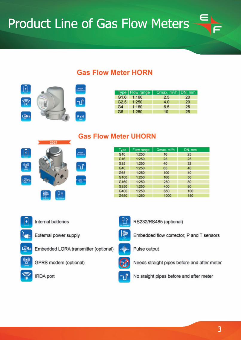
Gas Meter HORN
Gas Meter HORN is designed to measure the volume of natural gas or degasified hydrocarbon gas for households and public utilities adjusting the measured gas volume, and displaying the amount of consumed gas on the meter indicator with the ability to transfer information to a centralized accounting system.
4
PARAMETER, UNITS G1.6 G2.5 G4 G6 Max gas flow rate Qmax, m3/h 2,5 4,0 6,5 10,0 Transitional gas flow rate Qt, m3/h 0,16 0,16 0,4 0,4 Min gas flow rate Qmin, m3/h 0,016 0,016 0,04 0,04 Threshold gas flow rate Qthr, m3/h 0,004 0,004 0,008 0,008 Pressure loss at Рmax, Pa, not more 200 Diameter nominal DN15 DN20 Gas mixture type H, L, E, P/B Limits of relative error under normal conditions in the range of flow rates from Qmin to Qt, %, not more ± 3,0 Limits of relative error under normal conditions in the range of flow rates from Qt to Qmax, %, not more ± 1,5 Absolute error of temperature measurement, °С, not more ± 0,5 Max gas gauge pressure, kPa 50 Power supply Lithium battery 3,6 V Time of autonomous operation, not less 10 years Display LCD, one line 10 symbols Optical port IEC 62056-21 Verification period 8 years Ingress Protection Level IP67 Overall dimensions, mm, not more 110 х 120 х 100 Mounting dimensions: - distance between inlet and outlet pipes, mm, not more 110 - inlet and outlet pipes with G1/2̀ ̀ G3/4̀` Mounting options horizontal, vertical Meter weight, kg, not more 1,0
Low-Flow Gas Flow Meters HORN
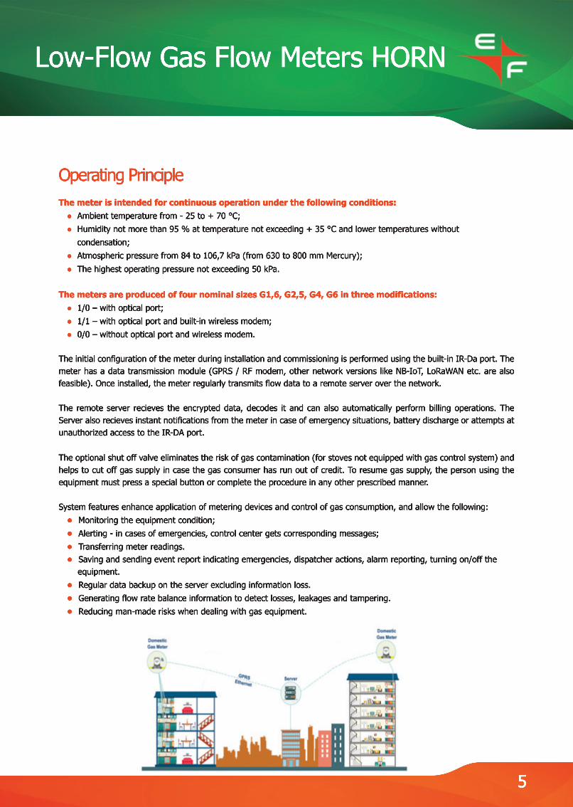
Operating PrincipleThe meter is intended for continuous operation under the following conditions: ● Ambient temperature from - 25 to + 70 °С; ● Humidity not more than 95 % at temperature not exceeding + 35 °С and lower temperatures without condensation; ● Atmospheric pressure from 84 to 106,7 kPa (from 630 to 800 mm Mercury); ● The highest operating pressure not exceeding 50 kPa.
The meters are produced of four nominal sizes G1,6, G2,5, G4, G6 in three modifications: ● 1/0 – with optical port; ● 1/1 – with optical port and built-in wireless modem; ● 0/0 – without optical port and wireless modem.
TheThe initial configuration of the meter during installation and commissioning is performed using the built-in IR-Da port. The meter has a data transmission module (GPRS / RF modem, other network versions like NB-IoT, LoRaWAN etc. are also feasible). Once installed, the meter regularly transmits flow data to a remote server over the network.
The remote server recieves the encrypted data, decodes it and can also automatically perform billing operations. The Server also recieves instant notifications from the meter in case of emergency situations, battery discharge or attempts at unauthorized access to the IR-DA port.
TheThe optional shut off valve eliminates the risk of gas contamination (for stoves not equipped with gas control system) and helps to cut off gas supply in case the gas consumer has run out of credit. To resume gas supply, the person using the equipment must press a special button or complete the procedure in any other prescribed manner.
System features enhance application of metering devices and control of gas consumption, and allow the following: ● Monitoring the equipment condition; ● Alerting - in cases of emergencies, control center gets corresponding messages; ● Transferring meter readings. ● Saving and sending event report indicating emergencies, dispatcher actions, alarm reporting, turning on/off the equipment. ● Regular data backup on the server excluding information loss. ● Generating flow rate balance information to detect losses, leakages and tampering. ● Reducing man-made risks when dealing with gas equipment.
5
Ultrasonic Gas Flow Meters
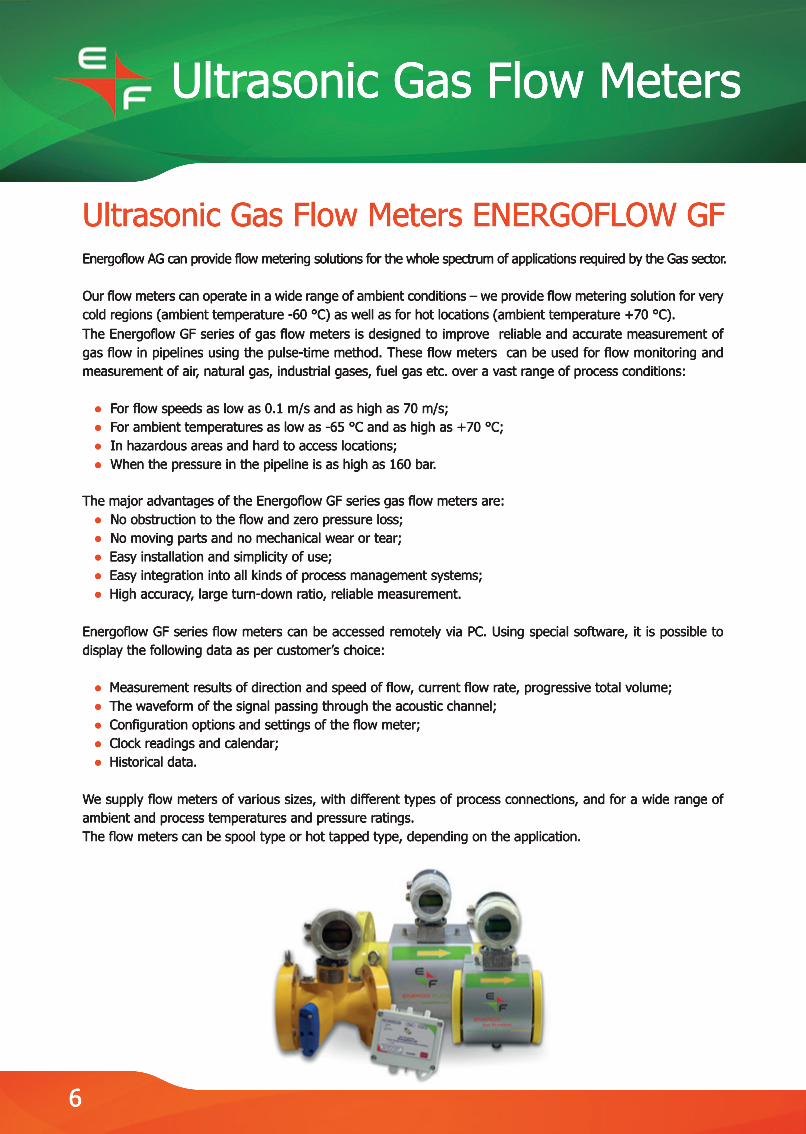
Ultrasonic Gas Flow Meters ENERGOFLOW GF Energoflow AG can provide flow metering solutions for the whole spectrum of applications required by the Gas sector.
Our flow meters can operate in a wide range of ambient conditions – we provide flow metering solution for very cold regions (ambient temperature -60 °C) as well as for hot locations (ambient temperature +70 °C).TheThe Energoflow GF series of gas flow meters is designed to improve reliable and accurate measurement of gas flow in pipelines using the pulse-time method. These flow meters can be used for flow monitoring and measurement of air, natural gas, industrial gases, fuel gas etc. over a vast range of process conditions:
● For flow speeds as low as 0.1 m/s and as high as 70 m/s; ● For ambient temperatures as low as -65 °C and as high as +70 °C; ● In hazardous areas and hard to access locations; ● When the pressure in the pipeline is as high as 160 bar.
The major adThe major advantages of the Energoflow GF series gas flow meters are: ● No obstruction to the flow and zero pressure loss; ● No moving parts and no mechanical wear or tear; ● Easy installation and simplicity of use; ● Easy integration into all kinds of process management systems; ● High accuracy, large turn-down ratio, reliable measurement.
EneEnergoflow GF series flow meters can be accessed remotely via PC. Using special software, it is possible to display the following data as per customer’s choice:
● Measurement results of direction and speed of flow, current flow rate, progressive total volume; ● The waveform of the signal passing through the acoustic channel; ● Configuration options and settings of the flow meter; ● Clock readings and calendar; ● Historical data.
WWe supply flow meters of various sizes, with different types of process connections, and for a wide range of ambient and process temperatures and pressure ratings.The flow meters can be spool type or hot tapped type, depending on the application.
6

Ultrasonic Gas Flow Meters
TECHNICAL CHARACTERISTICS: DN, Dimension Threshold Qthr Minimal Qmin Transition, Qt Maximal Qmax mm type 50 G100 0,7 1 8 160 80 G250 1,9 2,7 20 400 100 G400 3 4,2 33 650 150 G1000 6,8 9,5 80 1600 200 G1600 12 17 125 2500 250 G2500 19 26 200 4000 300 G4000 28 38 325 6500 400 G6500 47 67 500 10000 500 G10000 71 100 800 16000
7
CERTIFIED

Ultrasonic Gas Flow Meters
Energoflow Ultrasonic Flow Meter GFE 212 for In-situ Installation
Ultrasonic gas flow meter Energoflow GFE 212 is a brilliant example of genius engineering for achieving optimal solution for gas flow measurement in large pipes and in cases where installation of inline meters is technically or commercially not viable. The meter comprises electroacoustic transducers being hot tapped into the existing pipeline and connected to a remote electronic unit.
BBesides cost reduction, especially in the case of large pipelines where the flow meter body constitutes a major part of the cost of the device and installation calls for a capital effort, Energoflow GFE 212 gas flow meters provide all the traditional advantages of pulse-time ultrasonic technology – no pressure loss, no moving parts, reliable and accurate measurement and easy servicing. They can be installed on pipelines 200 mm up to 4000 mm in size and can be used for a wide range of media like natural gas, oil gas, flue gas, coal gas etc.
TECHNICAL CHARACTERISTICS DN, Standard Flow rate, m3/h mm size Threshold Qthr Minimal Qmin Transitional Qt Maximal Qmax 200 G1600 12,0 17,0 125,0 2500,0 250 G2500 19,0 26,0 200,0 4000,0 300 G4000 27,0 38,0 325,0 6500,0 400 G6500 48,0 67,0 500,0 10000,0 500 G10000 71,0 100,0 800,0 16000,0 600 G16000 111,0 160,0 1250,0 25000,0 800 G25000 177,0 250,0 2000,0 40000,0 1000 G40000 288,0 400,0 3250,0 65000,0 1200 G65000 470,0 670,0 5000,0 100000,0 1600 G100000 700,0 1000,0 8000,0 160000,0 2000 G160000 1110,0 1600,0 12500,0 250000,0 2500 G250000 1900,0 2700,0 20000,0 400000,0 3000 G400000 2800,0 4000,0 32500,0 650000,0 4000 G650000 4700,0 6700,0 50000,0 1000000,0
8
Ultrasonic Gas Flow Meters
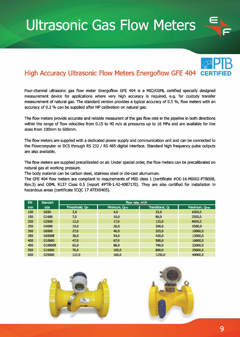
High Accuracy Ultrasonic Flow Meters Energoflow GFE 404
Four-channel ultrasonic gas flow meter Energoflow GFE 404 is a MID/OIML certified specially designed measurement device for applications where very high accuracy is required, e.g. for custody transfer measurement of natural gas. The standard version provides a typical accuracy of 0.5 %, flow meters with an accuracy of 0.2 % can be supplied after HP calibration on natural gas.
TheThe flow meters provide accurate and reliable measurent of the gas flow rate in the pipeline in both directions within the range of flow velocities from 0.15 to 40 m/s at pressures up to 16 MPa and are available for line sizes from 100mm to 600mm.
The flow meters are supplied with a dedicated power supply and communication unit and can be connected to the Flowcomputer or DCS through RS 232 / RS 485 digital interface. Standard high frequency pulse outputs are also available.
TheThe flow meters are supplied precalibrated on air. Under special order, the flow meters can be precalibrated on natural gas at working pressure.The body material can be carbon steel, stainless steel or die-cast alumunium.The GFE 404 flow meters are compliant to requirements of MID class 1 (certificate #DE-16-MI002-PTB00B, Rev.3) and OIML R137 Class 0.5 (report #PTB-1.42-4087170). They are also certified for installation in hazardous areas (certificate ICQC 17 ATEX0405).
DN Standart Flow rate, m3/h mm size Threshhold, Qth Minimum, Qmin Transitional, Qt Maximum, Qmax 100 G650 3,0 4,0 33,0 1000,0 150 G1600 7,0 10,0 80,0 2500,0 200 G2500 12,0 17,0 125,0 4000,0 250 G4000 19,0 26,0 200,0 6500,0 300 G6500 27,0 40,0 325,0 10000,0 350 G6500E 38,0 54,0 420,0 13500,0 400 G10000 47,0 67,0 500,0 16000,0 450 G10000E 62,0 88,0 700,0 22000,0 500 G16000 70,0 100,0 800,0 25000,0 600 G25000 112,0 160,0 1250,0 40000,0
9
CERTIFIED
Ultrasonic Gas Flow Meters
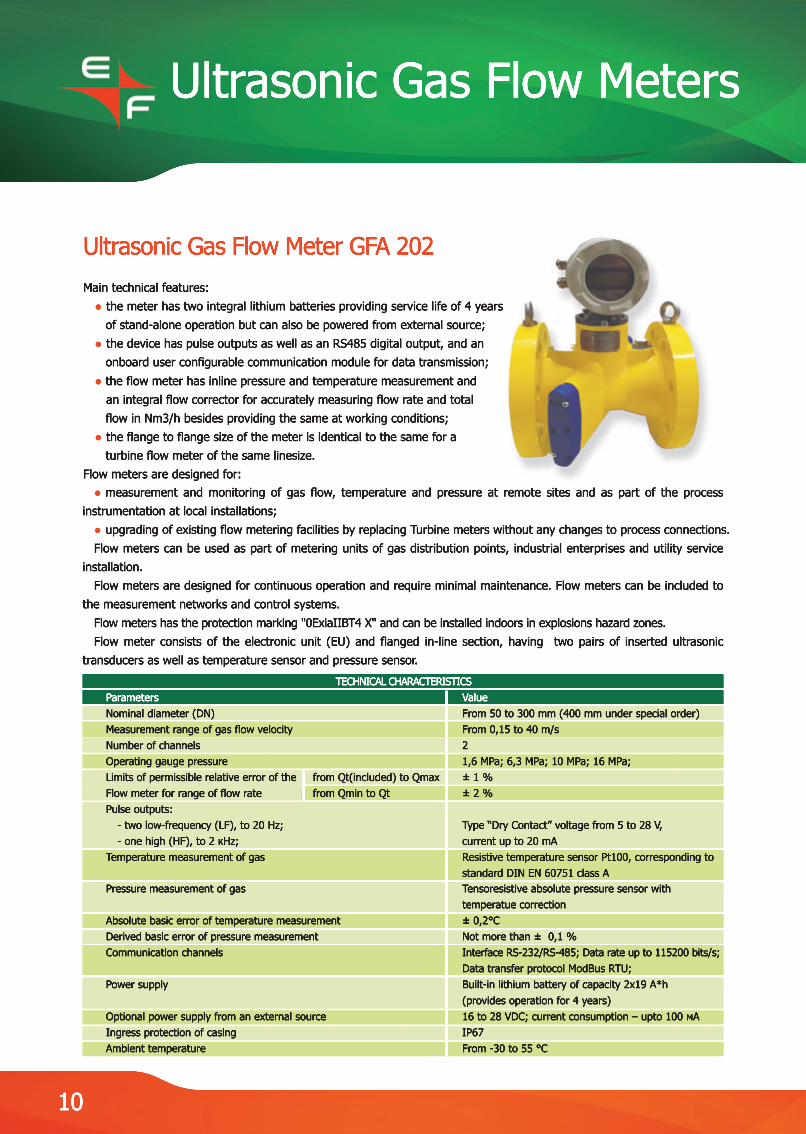
Ultrasonic Gas Flow Meter GFA 202Main technical features: ● the meter has two integral lithium batteries providing service life of 4 years of stand-alone operation but can also be powered from external source; ● the device has pulse outputs as well as an RS485 digital output, and an onboard user configurable communication module for data transmission; ● the flow meter has inline pressure and temperature measurement and an integral flow corrector for accurately measuring flow rate and total flow in Nm3/h besides providing the same at working conditions; ● the flange to flange size of the meter is identical to the same for a turbine flow meter of the same linesize.Flow meters are designed for: ● measurement and monitoring of gas flow, temperature and pressure at remote sites and as part of the process instrumentation at local installations; ● upgrading of existing flow metering facilities by replacing Turbine meters without any changes to process connections. Flow meters can be used as part of metering units of gas distribution points, industrial enterprises and utility service installation. Flow meters are designed for continuous operation and require minimal maintenance. Flow meters can be included to the measurement networks and control systems. Flow meters has the protection marking "0ExiaIIBT4 X" and can be installed indoors in explosions hazard zones. Flow meter consists of the electronic unit (EU) and flanged in-line section, having two pairs of inserted ultrasonic transducers as well as temperature sensor and pressure sensor.
TECHNICAL CHARACTERISTICS Parameters Value Nominal diameter (DN) From 50 to 300 mm (400 mm under special order) Measurement range of gas flow velocity From 0,15 to 40 m/s Number of channels 2 Operating gauge pressure 1,6 MPa; 6,3 MPa; 10 MPa; 16 MPa; Limits of permissible relative error of the from Qt(included) to Qmax ± 1 % Flow meter for range of flow rate from Qmin to Qt ± 2 % Pulse outputs: - two low-frequency (LF), to 20 Hz; Type “Dry Contact” voltage from 5 to 28 V, - one high (HF), to 2 кHz; current up to 20 mA Temperature measurement of gas Resistive temperature sensor Pt100, corresponding to standard DIN EN 60751 class A Pressure measurement of gas Tensoresistive absolute pressure sensor with temperatue correction Absolute basic error of temperature measurement ± 0,2°С Derived basic error of pressure measurement Not more than ± 0,1 % Communication channels Interface RS-232/RS-485; Data rate up to 115200 bits/s; Data transfer protocol ModBus RTU; Power supply Built-in lithium battery of capacity 2x19 A*h (provides operation for 4 years) Optional power supply from an external source 16 to 28 VDC; current consumption – upto 100 мА Ingress protection of casing IP67 Ambient temperature From -30 to 55 °С
10

Ultrasonic Gas Flow Meters
Archive data: ● hourly - for every preceding hour - size of archive 1488 records (62 days); ● daily - for every preceding day - size of archive 730 records; ● power on/off instances - size of archive 512 records; ● emergency situations - size of archive 720 records; ● intervention - changing the adjustment parameters (size of archive 889 records).
Contol software program is used for recording, viewing and changing the settings of the flow meteContol software program is used for recording, viewing and changing the settings of the flow meter, recording and viewing of measurement data, as well as for reading data archive. This program allows you to view the archive data and modify the flow meter settings via a PC monitor and then upload the archive data to a file on the flow meter.The flow meter provides protection of settings and archive data from unauthorized changing by restricting access through a system of passwords and hardware based protection of configuration from being overwritten.
DN Standard Flow rate, m3/h mm size threshold, Qtreshold minimum, Qmin transitional, Qt maximum, Qmax 50 G160 0,2 1,0 8,0 250,0 80 G400 0,5 2,6 20,0 650,0 100 G650 0,8 4,0 33,0 1000,0 150 G1600 2,0 10,0 80,0 2500,0 200 G2500 3,4 17,0 133,0 4000,0 250 G4000 5,0 26,0 200,0 6500,0 300 G6500 8,0 40,0 325,0 10000,0 400 G10000 13,0 63,0 500,0 16000,0
11
Ultrasonic Liquid Flow Meters
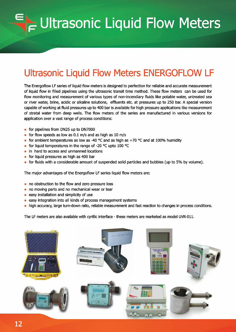
Ultrasonic Liquid Flow Meters ENERGOFLOW LF TheThe Energoflow LF series of liquid flow meters is designed to perfection for reliable and accurate measurement of liquid flow in filled pipelines using the ultrasonic transit time method. These flow meters can be used for flow monitoring and measurement of various types of non-incendiary fluids like potable water, untreated sea or river water, brine, acidic or alkaline solutions, effluents etc. at pressures up to 250 bar. A special version capable of working at fluid pressures up to 400 bar is available for high pressure applications like measurement of stratal water from deep wells. The flow meters of the series are manufactured in various versions for appapplication over a vast range of process conditions:
● for pipelines from DN25 up to DN7000● for flow speeds as low as 0.1 m/s and as high as 10 m/s● for ambient temperatures as low as -40 °C and as high as +70 °C and at 100% humidity● for liquid temperatures in the range of -20 °C upto 100 °C● in hard to access and unmanned locations● for liquid pressures as high as 400 bar● for fluids with a considerable amount of suspended solid particles and bubbles (up to 5% by volume).
The major advantages of the Energoflow LF series liquid flow meters are:
● no obstruction to the flow and zero pressure loss● no moving parts and no mechanical wear or tear● easy installation and simplicity of use● easy integration into all kinds of process management systems● high accuracy, large turn-down ratio, reliable measurement and fast reaction to changes in process conditions.
The LF meters aThe LF meters are also available with cyrillic interface - these meters are marketed as model UVR-011.
12
Ultrasonic Liquid Flow Meters
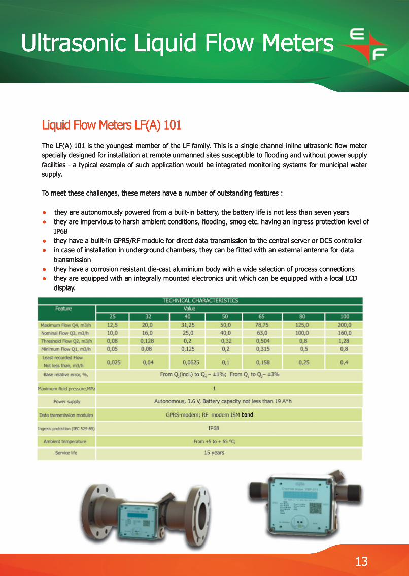
Liquid Flow Meters LF(A) 101The LF(A) 101 is the youngest member of the LF family. This is a single channel inline ultrasonic flow meter specially designed for installation at remote unmanned sites susceptible to flooding and without power supply facilities - a typical example of such application would be integrated monitoring systems for municipal water supply.
To meet these challenges, these meters have a number of outstanding features :
●● they are autonomously powered from a built-in battery, the battery life is not less than seven years● they are impervious to harsh ambient conditions, flooding, smog etc. having an ingress protection level of IP68● they have a built-in GPRS/RF module for direct data transmission to the central server or DCS controller● in case of installation in underground chambers, they can be fitted with an external antenna for data transmission● they have a corrosion resistant die-cast aluminium body with a wide selection of process connections●● they are equipped with an integrally mounted electronics unit which can be equipped with a local LCD display.
13
band
Ultrasonic Liquid Flow Meters
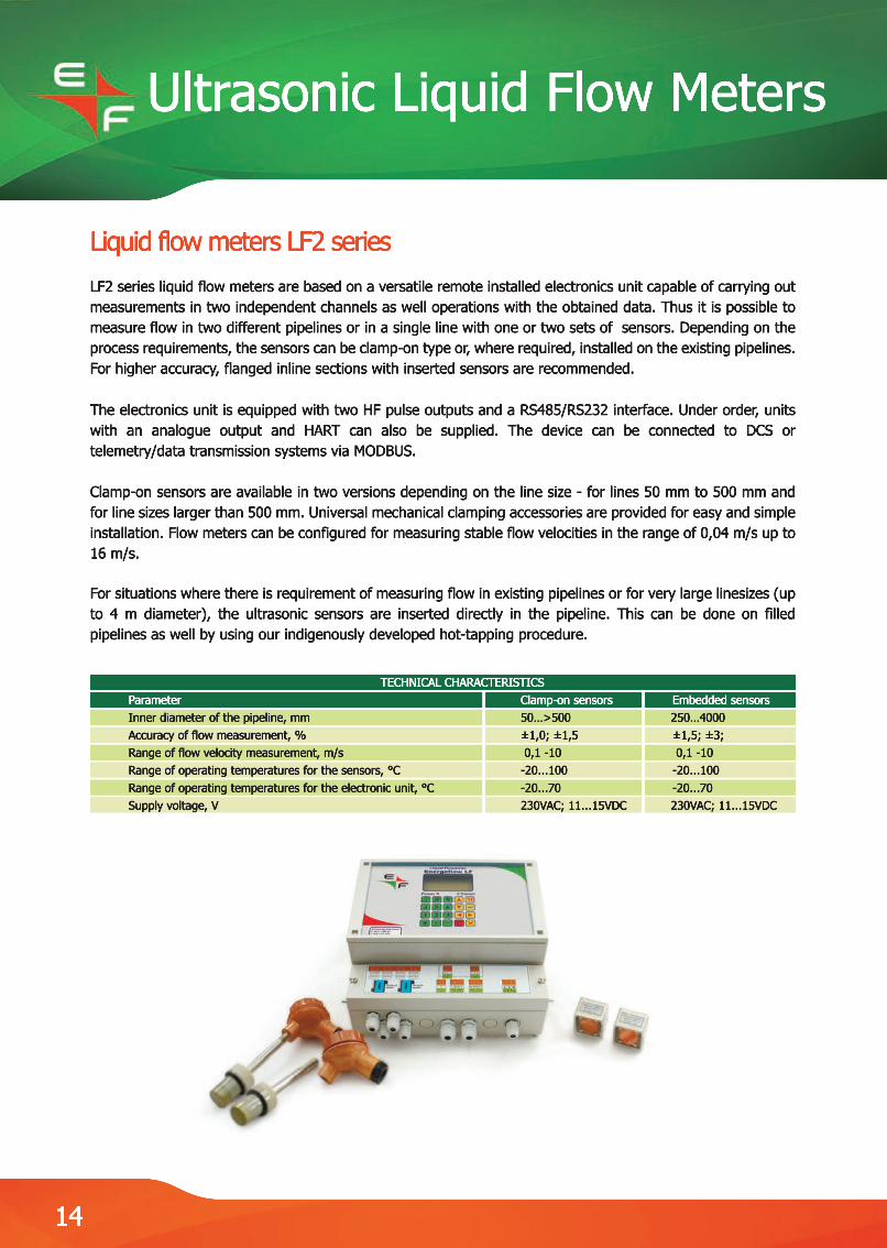
Liquid flow meters LF2 seriesLF2 series liquid flow meters are based on a versatile remote installed electronics unit capable of carrying out measurements in two independent channels as well operations with the obtained data. Thus it is possible to measure flow in two different pipelines or in a single line with one or two sets of sensors. Depending on the process requirements, the sensors can be clamp-on type or, where required, installed on the existing pipelines. For higher accuracy, flanged inline sections with inserted sensors are recommended.
TheThe electronics unit is equipped with two HF pulse outputs and a RS485/RS232 interface. Under order, units with an analogue output and HART can also be supplied. The device can be connected to DCS or telemetry/data transmission systems via MODBUS.
Сlamp-on sensors are available in two versions depending on the line size - for lines 50 mm to 500 mm and for line sizes larger than 500 mm. Universal mechanical clamping accessories are provided for easy and simple installation. Flow meters can be configured for measuring stable flow velocities in the range of 0,04 m/s up to 16 m/s.
FFor situations where there is requirement of measuring flow in existing pipelines or for very large linesizes (up to 4 m diameter), the ultrasonic sensors are inserted directly in the pipeline. This can be done on filled pipelines as well by using our indigenously developed hot-tapping procedure.
TECHNICAL CHARACTERISTICS Parameter Clamp-on sensors Embedded sensors Inner diameter of the pipeline, mm 50…>500 250…4000 Accuracy of flow measurement, % ±1,0; ±1,5 ±1,5; ±3; Range of flow velocity measurement, m/s 0,1 -10 0,1 -10 Range of operating temperatures for the sensors, °C -20...100 -20...100 Range of operating temperatures for the electronic unit, °C -20...70 -20...70 Supply voltage, V 230VAC; 11...15VDC 230VAC; 11...15VDC
14
Ultrasonic Liquid Flow Meters
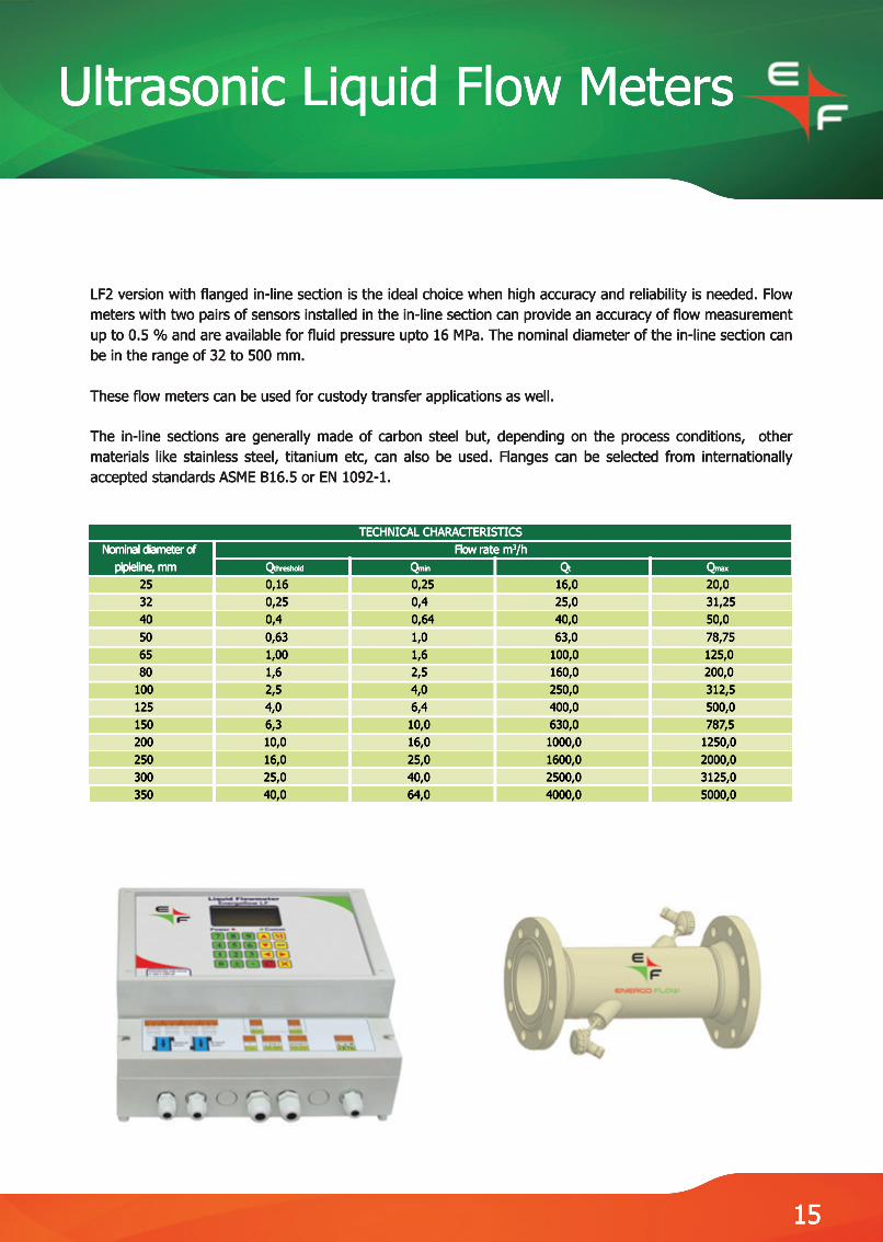
LF2 version with flanged in-line section is the ideal choice when high accuracy and reliability is needed. Flow meters with two pairs of sensors installed in the in-line section can provide an accuracy of flow measurement up to 0.5 % and are available for fluid pressure upto 16 MPa. The nominal diameter of the in-line section can be in the range of 32 to 500 mm.
These flow meters can be used for custody transfer applications as well.
TheThe in-line sections are generally made of carbon steel but, depending on the process conditions, other materials like stainless steel, titanium etc, can also be used. Flanges can be selected from internationally accepted standards ASME B16.5 or EN 1092-1.
TECHNICAL CHARACTERISTICS Nominal diameter of Flow rate m3/h pipleline, mm Qthreshold Qmin Qt Qmax 25 0,16 0,25 16,0 20,0 32 0,25 0,4 25,0 31,25 40 0,4 0,64 40,0 50,0 50 0,63 1,0 63,0 78,75 65 1,00 1,6 100,0 125,0 80 1,6 2,5 160,0 200,0 100 2,5 4,0 250,0 312,5 125 4,0 6,4 400,0 500,0 150 6,3 10,0 630,0 787,5 200 10,0 16,0 1000,0 1250,0 250 16,0 25,0 1600,0 2000,0 300 25,0 40,0 2500,0 3125,0 350 40,0 64,0 4000,0 5000,0
15
Ultrasonic Liquid Flow Meters
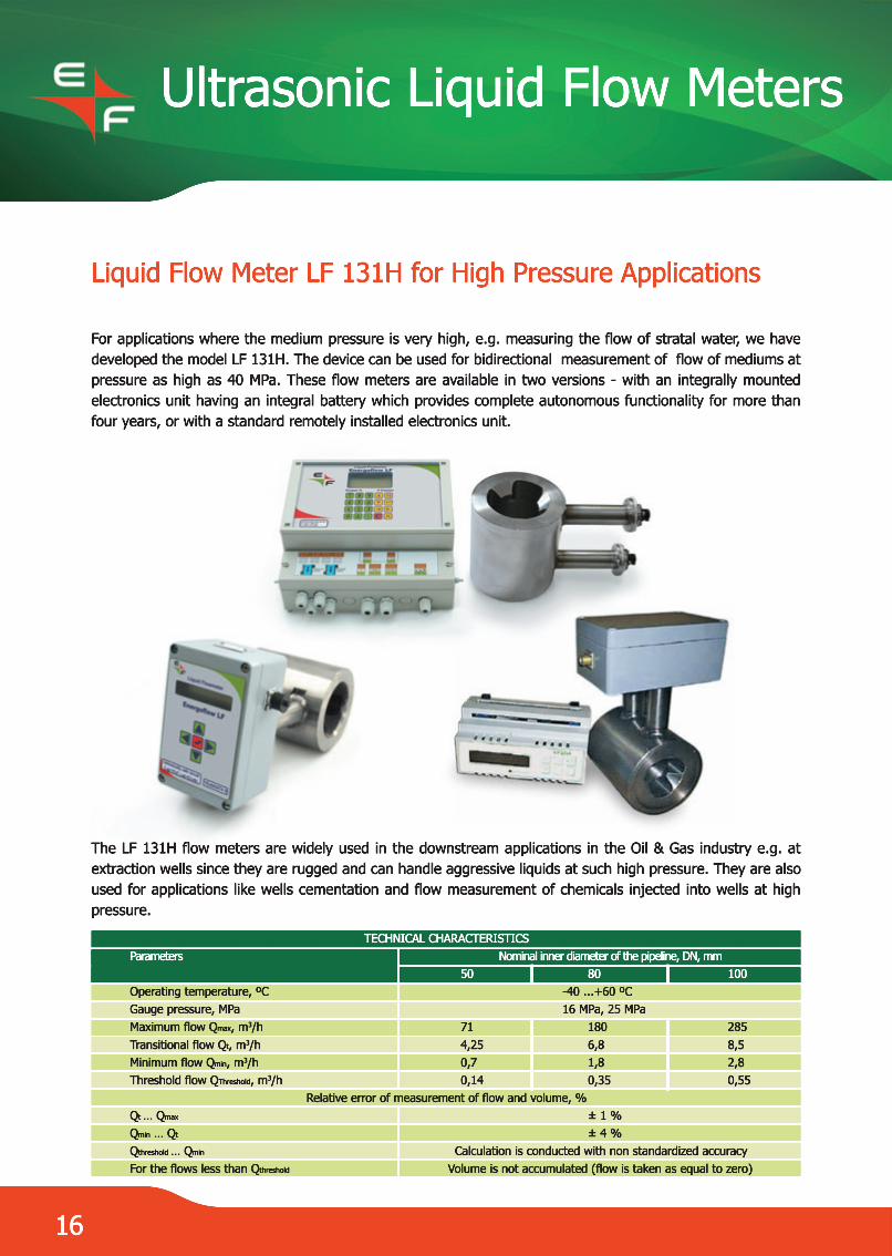
Liquid Flow Meter LF 131H for High Pressure Applications
For applications where the medium pressure is very high, e.g. measuring the flow of stratal water, we have developed the model LF 131H. The device can be used for bidirectional measurement of flow of mediums at pressure as high as 40 MPa. These flow meters are available in two versions - with an integrally mounted electronics unit having an integral battery which provides complete autonomous functionality for more than four years, or with a standard remotely installed electronics unit.
TheThe LF 131H flow meters are widely used in the downstream applications in the Oil & Gas industry e.g. at extraction wells since they are rugged and can handle aggressive liquids at such high pressure. They are also used for applications like wells cementation and flow measurement of chemicals injected into wells at high pressure.
TECHNICAL CHARACTERISTICS Parameters Nominal inner diameter of the pipeline, DN, mm 50 80 100 Operating temperature, ºC -40 ...+60 ºC Gauge pressure, MPa 16 MPa, 25 MPa Maximum flow Qmax, m3/h 71 180 285 Transitional flow Qt, m3/h 4,25 6,8 8,5 Minimum flow Qmin, m3/h 0,7 1,8 2,8 Threshold flow QThreshold, m3/h 0,14 0,35 0,55
Relative error of measurement of flow and volume, % Qt … Qmax ± 1 % Qmin … Qt ± 4 % Qthreshold … Qmin Calculation is conducted with non standardized accuracy For the flows less than Qthreshold Volume is not accumulated (flow is taken as equal to zero)
16

Ultrasonic Liquid Flow Meters
Portable Ultrasonic Liquid Flow Meter Energoflow LF 2P2
The portable flow meter ENERGOFLOW LF 2P2 with clamp-on sensors is designed for use in field conditions for monitoring and measurement of flow of liquids eg. water, oil and oil products, industrial chemicals, solvents, etc. in fully filled pipelines. The set comes in a handy, easy to carry durable case and can be used for:
● single channel (accuracy ± 1.5%) and twin channel (accuracy ± 1%) flow measurements on a single pipeline●● real-time comparison or summation of flows in two adjacent pipelines (single channel mode per pipeline).
This set is a boon for repair teams and field engineers. The built-in digital oscillograph facility and in-line calibration function make installation and commissioning very fast, simple and easy.The flow meter can also be used as a fullfledged stand-alone liquid flow meter for in-situ installations in remote locations.
The complete set comprises of the following:
1 LF 2P2 – Electronic unit (twin channel) with LCD display and keyboard 1 pc. 2 Electroacoustic transducer 4 pcs. 3 Removable plates (for clamp-on installation) 16 pcs. 4 Power unit / Battery charger 5V, 1А 1 pc. 5 Thickness gauge 1 pc. 6 Water-resistant grease 1 pc. 7 Accumulator charger 1 pc. 8 Tapping hammer with screwdriver 1 pc 9 Measuring roulette 1 pc 10 Standards strip for calibration of thickness gauge 1 pc 11 Connecting cables for transducers with connectors, 2 x 10 m 2 sets 12 Carrying case 1 pc 13 Accessories for installation on pipes (chains and clamps) 1 set
Manufacturer's warranty certificate, instruction manual and software CD with cable (for connecting the electronic unit to PC for data transfer and configuration) are provided with each set.
TECHNICAL CHARACTERISTICS Parameter Value Pipe inner diameter, mm 50-3200 Accuracy of flow measurement, % ±1,0; ±1,5 Range of flow velocity measurement, m/s 0,1-10 Range of operating temperatures for the sensors, °C -20…+90 Range of operating temperatures for the electronic unit, °C +5…+45 Relative error of measurement of flow rate and volume, mm ±0,2 Supply voltage, VAC 220 Time of autonomous operation from accumulator battery up to 10 hours
17

Metrological Equipment
18
Reference Turbine Gas Meters EFS-T
Reference Turbine Gas Meters EFS-T are intended for installation on reference calibration rigs for calibration and verification of gas meters of any type with air as operating environment. The meters are equipped with electronics unit (EU) and rotary transducer with mounted binary pulse-frequency sensors and pressure sensors.
TheThe meter EFS-T is intended for measuring the volume of gas passing through its input channel of circular section. The gas flow volume is transmitted to a PC via the EU. The meters are designed for vertical installation on the reference equipment with DN 50 mm, DN 80 mm, DN 100 mm, DN 150 mm, DN 200 mm, DN 250 mm, DN 300 mm, DN 400 mm.
Connection between the meter and PC is carried out via RS-485. Exchange protocol - ModBus RTU. “Start-stop” synchronization is of two-wire type based on the communication line RS-485.
Historical data:● hourly - for every preceding hour - size of archive 1488 records (62 days)●● daily - for every preceding day - size of archive 730 records● power on/off events - size of archive 512 messages● emergency situations - size of archive 720 messages● intervention - changing the adjustment parameters (size of archive 889 messages).
DN4004003002502001501501008050
Standard size G6500 G4000 G4000 G2500 G1600 G1000 G1000G400G250G100
Qmax, m3/h10000650065004000250016001600650400160
Qmin, m3/h500325325200125808032,5208
Parameters
Process mediumOperating pressure, MPa Limits of basic relative permissible error, at least % Repeatability, at least % Repeating accuracy within 2 years, at least % Frequency output with adjusted multiplication factor Fmax, kHz Frequency output with adjusted multiplication factor Fmax, kHz Signal of flow rate excess for the emergency system shutdown Loading capacitance of emergency output shutdown: Voltage, V, maxCurrent, mA, maxOperating conditions:- temperature of operating environment and ambient air оС, at least- relative humidity of air at temperature +25 - relative humidity of air at temperature +25 оС, %- atmospheric pressure, kPaPower consumption, W, max Supply voltage, DCV Lifetime, min. years
Value General industrial Explosion-proof application design design
Air, gas1,6 4,0 6,3± 0,2± 0,03± 0,03± 0,15
Type «dry contact»
2420
15 up to 25up to 80up to 80
from 84,0 up to 106,7 0,5 6,0
from 9 up to 2410

Metrological Equipment
19
DN, mm
50
80
100
150
200
250 250
300
400
Rating, MPa1,64,06,31,64,06,36,31,64,06,31,64,06,31,61,64,06,31,64,06,31,64,04,06,31,64,06,3
L, mm
150
240
300
450
600
750750
900
1200
D1, mm125125135160160170170180190200240250280295295320345355385400410450450460580670715
n
4
8
8
8
12
1212
121616
16
d, mm181622181622222220262224332222273326303926303039304248
Order code for reference turbine gas meter EFS-T
1 2 3 4 5 6 7 8 9 10 11 12 13 EFS- T D G N P Ak Sm Mp I Dp Dt S
# Elements Meter's characteristics Legend 1 EFS- Type of the reference meter 2 Т Type of meter sections: Т - turbine 3 D Nominal meter diameter, mm 4 G Meter standard size 5 5 N Flow range: 20 – 1/20 Qmax, 30 – 1/30 Qmax 6 P Absolute operating pressure (1,6; 4,0; 6,3) МPа 7 Ak Meter accuracy: 0,2% 8 Sm Counting mechanism: 1 – yes, 0 – no 9 Mp Availability of seal oil pump: 1 – yes, 0 – no 10 I Type and quantity of pulse sensors: 0 – no, 1 – one low-frequency (LF), 2 – one high (HF), 3 – one low-frequency (LF) and one high (HF), 4 – two high (HF), 5 – one low-frequency (LF) and two high (HF) 11 Dp Availability of the pressure sensor: 1 – yes, 0 – no 12 Dt Availability of the temperature sensor: 1 – yes, 0 – no 13 13 S Section material: S – Steel.20, А – stainless steel
Legend explanation of typical order codes is given in Table
Control software program is used for recording, viewing and changing the settings of the flow meter, recording and viewing of measurement data, as well as for reading data archive.
This program allows you to view the archive data and modify the flow meter settings via a PC monitor and then upload the archive data to a file on the flow meter. The flow meter provides protection of settings and archive data from unauthorized changing by restricting access through a system of passwords and hardware based protection of configuration from being overwritten.
Metrological Equipment
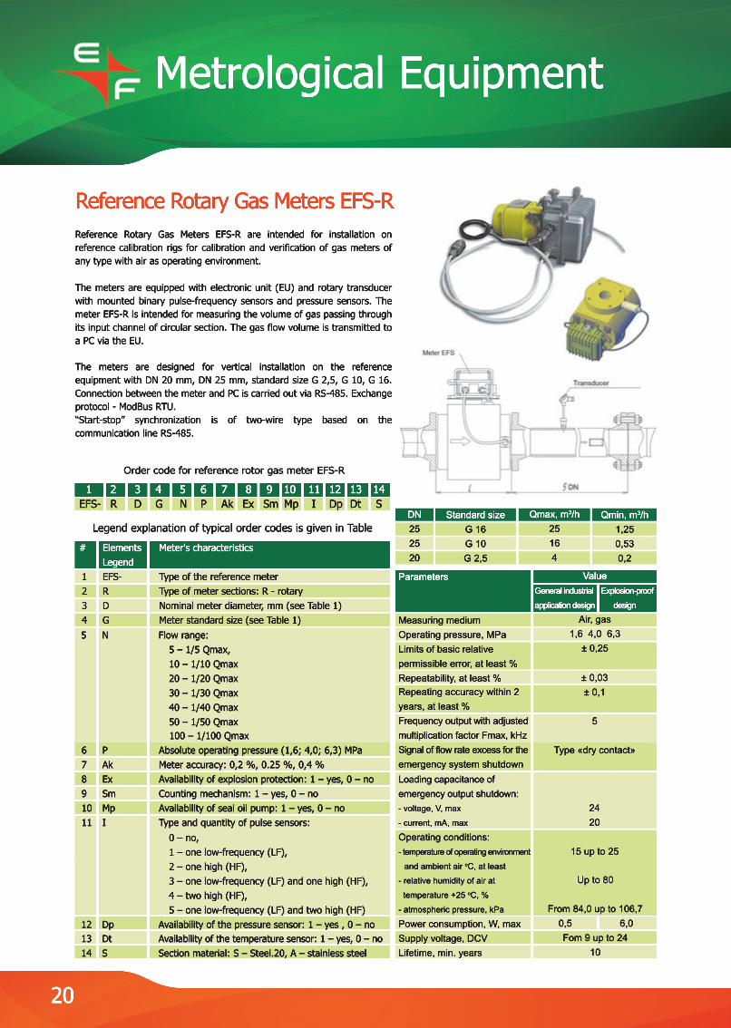
Reference Rotary Gas Meters EFS-R
Order code for reference rotor gas meter EFS-R
1 2 3 4 5 6 7 8 9 10 11 12 13 14 EFS- R D G N P Ak Ex Sm Mp I Dp Dt S
# Elements Meter's characteristics Legend 1 EFS- Type of the reference meter 2 R Type of meter sections: R - rotary 3 D Nominal meter diameter, mm (see Table 1) 4 G Meter standard size (see Table 1) 5 5 N Flow range: 5 – 1/5 Qmax, 10 – 1/10 Qmax 20 – 1/20 Qmax 30 – 1/30 Qmax 40 – 1/40 Qmax 50 – 1/50 Qmax 100 – 1/100 Qmax 6 P Absolute operating pressure (1,6; 4,0; 6,3) МPа 7 Ak Meter accuracy: 0,2 %, 0.25 %, 0,4 % 8 Ex Availability of explosion protection: 1 – yes, 0 – no 9 Sm Counting mechanism: 1 – yes, 0 – no 10 Mp Availability of seal oil pump: 1 – yes, 0 – no 11 I Type and quantity of pulse sensors: 0 – no, 1 – one low-frequency (LF), 2 – one high (HF), 3 – one low-frequency (LF) and one high (HF), 4 – two high (HF), 5 – one low-frequency (LF) and two high (HF) 12 Dp Availability of the pressure sensor: 1 – yes , 0 – no 13 13 Dt Availability of the temperature sensor: 1 – yes, 0 – no 14 S Section material: S – Steel.20, А – stainless steel
Legend explanation of typical order codes is given in Table
Parameters
Measuring mediumOperating pressure, MPa Limits of basic relative permissible error, at least % Repeatability, at least % Repeating accuracy within 2 Repeating accuracy within 2 years, at least % Frequency output with adjusted multiplication factor Fmax, kHz Signal of flow rate excess for the emergency system shutdown Loading capacitance of Loading capacitance of emergency output shutdown: - voltage, V, max
- current, mA, max
Operating conditions:- temperature of operating environment
and ambient air оС, at least
- relative humidity of air at - relative humidity of air at
temperature +25 оС, %
- atmospheric pressure, kPa
Power consumption, W, max Supply voltage, DCV Lifetime, min. years
ValueGeneral industrial Explosion-proof
application design design
Air, gas1,6 4,0 6,3± 0,25
± 0,03± 0,03± 0,1
5
Type «dry contact»
2420
15 up to 25
Up to 80Up to 80
From 84,0 up to 106,7 0,5 6,0
Fom 9 up to 2410
DN252520
Standard sizeG 16G 10G 2,5
Qmax, m3/h25164
Qmin, m3/h1,250,530,2
Reference Rotary Gas Meters EFS-R are intended for installation on reference calibration rigs for calibration and verification of gas meters of any type with air as operating environment.
TheThe meters are equipped with electronic unit (EU) and rotary transducer with mounted binary pulse-frequency sensors and pressure sensors. The meter EFS-R is intended for measuring the volume of gas passing through its input channel of circular section. The gas flow volume is transmitted to a PC via the EU.
TheThe meters are designed for vertical installation on the reference equipment with DN 20 mm, DN 25 mm, standard size G 2,5, G 10, G 16. Connection between the meter and PC is carried out via RS-485. Exchange protocol - ModBus RTU. “Start-stop” synchronization is of two-wire type based on the communication line RS-485.
20
21
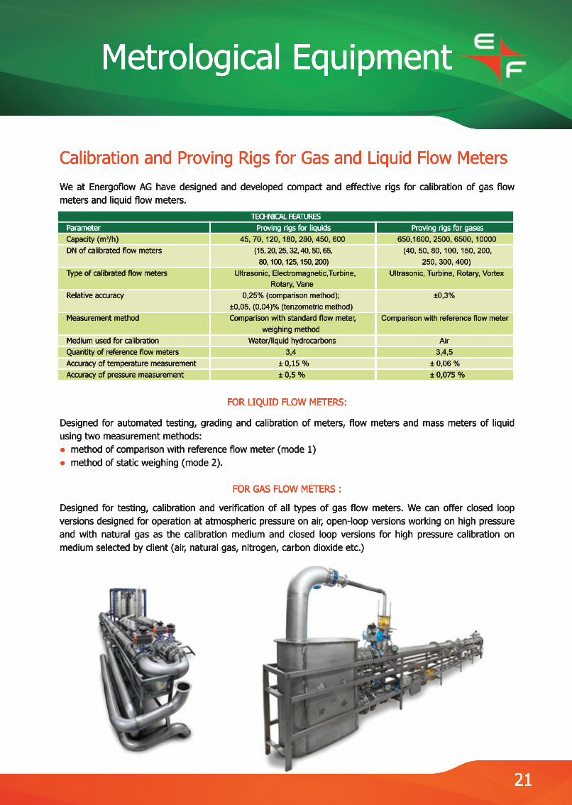
Calibration and Proving Rigs for Gas and Liquid Flow MetersWe at Energoflow AG have designed and developed compact and effective rigs for calibration of gas flow meters and liquid flow meters.
FOR LIQUID FLOW METERS:
Designed for automated testing, grading and calibration of meters, flow meters and mass meters of liquid using two measurement methods:●● method of comparison with reference flow meter (mode 1)● method of static weighing (mode 2).
FOR GAS FLOW METERS :
Designed for testing, calibration and verification of all types of gas flow meters. We can offer closed loop versions designed for operation at atmospheric pressure on air, open-loop versions working on high pressure and with natural gas as the calibration medium and closed loop versions for high pressure calibration on medium selected by client (air, natural gas, nitrogen, carbon dioxide etc.)
TECHNICAL FEATURES Parameter Proving rigs for liquids Proving rigs for gases Capacity (m3/h) 45, 70, 120, 180, 280, 450, 600 650,1600, 2500, 6500, 10000 DN of calibrated flow meters (15, 20, 25, 32, 40, 50, 65, (40, 50, 80, 100, 150, 200, 80, 100, 125, 150, 200) 250, 300, 400) Type of calibrated flow meters Ultrasonic, Electromagnetic,Turbine, Ultrasonic, Turbine, Rotary, Vortex Rotary, Vane Relative accuracy 0,25% (comparison method); ±0,3% ±0,05, (0,04)% (tenzometric method) Measurement method Comparison with standard flow meter, Comparison with reference flow meter weighing method Medium used for calibration Water/liquid hydrocarbons Air Quantity of reference flow meters 3,4 3,4,5 Accuracy of temperature measurement ± 0,15 % ± 0,06 % Accuracy of pressure measurement ± 0,5 % ± 0,075 %
Metrological Equipment
Metrological Equipment
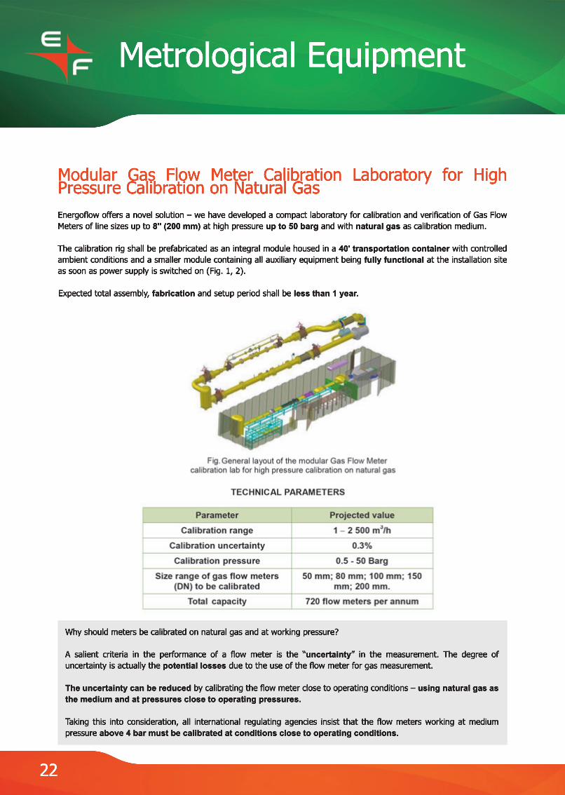
Modular Gas Flow Meter Calibration Laboratory for High Pressure Calibration on Natural GasEnergoflow offers a novel solution – we have developed a compact laboratory for calibration and verification of Gas Flow Meters of line sizes up to 8'' (200 mm) at high pressure up to 50 barg and with natural gas as calibration medium.
The calibration rig shall be prefabricated as an integral module housed in a 40' transportation container with controlled ambient conditions and a smaller module containing all auxiliary equipment being fully functional at the installation site as soon as power supply is switched on (Fig. 1, 2).
Expected total assemblExpected total assembly, fabrication and setup period shall be less than 1 year.
Why should meters be calibrated on natural gas and at working pressure?
A salient criteria in the performance of a flow meter is the “uncertainty” in the measurement. The degree of uncertainty is actually the potential losses due to the use of the flow meter for gas measurement.
The uncertainty can be reduced by calibrating the flow meter close to operating conditions – using natural gas as the medium and at pressures close to operating pressures.
TTaking this into consideration, all international regulating agencies insist that the flow meters working at medium pressure above 4 bar must be calibrated at conditions close to operating conditions.
22
Additional
Portable Standards (Liquids, Gas)
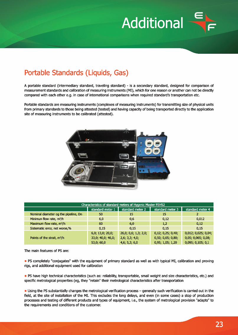
A portable standard (intermediary standard, traveling standard) - is a secondary standard, designed for comparison of measurement standards and calibration of measuring instruments (MI), which for one reason or another can not be directly compared with each other e.g. in case of international comparisons when required standard’s transportation etc.
PPortable standards are measuring instruments (complexes of measuring instruments) for transmitting size of physical units from primary standards to those being attested (tested) and having capacity of being transported directly to the application site of measuring instruments to be calibrated (attested).
The main features of PS are:
● PS completely "conjugates" with the equipment of primary standard as well as with typical MI, calibration and proving rigs, and additional equipment used for calibration
●● PS have high technical characteristics (such as: reliability, transportable, small weight and size characteristics, etc.) and specific metrological properties (eg, they "retain" their metrological characteristics after transportation
● Using the PS substantially changes the metrological verification process – generally such verification is carried out in the field, at the site of installation of the MI. This excludes the long delays, and even (in some cases) a stop of production processes and testing of different products and types of equipment, i.e., the system of metrological provision "adapts" to the requirements and conditions of the customer.
Characteristics of standard meters of Hygenic Master FEH52 standard meter 1 standard meter 2 standard meter 3 standard meter 4 Nominal diameter og the pipeline, Dn 50 15 15 2 Minimun flow rate, m3/h 6,0 0,6 0,12 0,012 Maximum flow rate, m3/h 60 6,0 1,2 0,12 Sistematic error, not worse,% 0,15 0,15 0,15 0,15 6,0; 13,0; 20,0; 26,0; 0,6; 1,3; 2,0; 0,12; 0,25; 0,40; 0,012; 0,025; 0,04; Points of the strait, m3/h 33,0; 40,0; 46,0; 2,6; 3,3; 4,0; 0,50; 0,65; 0,80; 0,05; 0,065; 0,08; 53,0; 60,0 4,6; 5,3; 6,0 0,95; 1,05; 1,20 0,095; 0,105; 0,1
23

Additional
Ultrasonic Non-Intrusive Pig Detector ULIS-A ULIS-A is a non-intrusive ultrasonic pig passage indicator designed for reliable detection of all kinds of pigs used for pigging of filled pipelines. It also provides indication and estimation of accumulated debris in front of the pig as well as the effectiveness of the pigging procedure. The device is certified as intrinsically safe for use in hazardous areas.
TheThe pig detector comprises an ultrasonic non-intrusive sensor clamped to the outside of the pipe and a remotely installed electronic unit. The clamp-on design of the sensor allows the device to be used for all pipe sizes. The electronic unit provides visual indication of pig passage as well a dry relay output signal for integration into existing control systems. Besides, the electronic unit provides archiving of up to 120 events of pig detection and automatic reset functions. With the help of specialized software provided, graphical visualization of the approach of the debris plug as well as pig/sphere passage and change in density of the fluid is possible.
The major adThe major advantages of the ULIS-A pig detector are:● Non-intrusive design provides zero pressure drop and no obstruction to the flow or the pig and allows for all kinds of applications - high pressure, sour service etc ● Any type of pig, sphere etc. can be detected in both directions● There are no mechanical moving parts - so no wear or tear, minimum servicing● The active nature of the ultrasonic device guarantees reliable pig detection eliminating false alarms due to outside interference.
Detectors are certified for use in hazardous area and have EC-Type Examination certificate Detectors are certified for use in hazardous area and have EC-Type Examination certificate FTZU 18 ATEX 0009X.
24

Additional
EASY INSTALLATION
1. Transducers of the detector should be installed on the pipelines to detect large-size objects (including pigs, separating balls, gauges, diagnostics devices etc.), propelled by the liquid flow in the pipelines under pressure for determination of the moment when the object is crossing the pipeline section under control. A corresponding warning signal is emitted to the data collection system or to the Advanced Communications System (ACS).2.2. Detector also provides the detection of the so-called «paraffin plugs» (referred as plugs) in the oil pipelines.3. Detector is designed for the pipelines with passage diameter DN from 80 up to 500 mm and from 350 up to 1200 mm, and wall thickness up to 60 mm. a. Detector consists of a electronic unit (EU) and an electroacoustic transducer (EAT) attached to the pipeline surface by a mounting tool. EAT is connected to the EU by a 4-wire cable. b. EAT transmits and receives an ultrasonic signal. c. ULIS-A SU is intended for installation both indoors and outdoors of the explosion hazardous zones.
EAT is designed in explosion safe enclosure and can be installed indoors and outdoors in the explosion hazardous zones according to rules, regulating electrical equipment application in the explosion hazardous zones.
Parameters of the indicator Value Diameter of the pipeline, mm 80 – 1200 Pig velocity, km/h 1 – 8 Pig length, m 1 – 2 Ambient temperature EU: -10 … +50 °C; EAT: -60 ... +50 °C Voltage 230 V, 50 Hz Power consumption, W, no more 6 1. "Dry contact" "Event" 30V, 200mA 2. "Dry contact" "Fuse" 30V, 200mA 3. Current output 4 – 20 mA 4. Serial interface RS-232/RS485 Distance from the gauge up to the electronic unit, m, max 150 Certification Sensor: II 2G Ex ib IIB T4 Gb Electronics block : II (2)G [Ex ib Gb] IIB
25

Additional
Skid Design and FabricationKeeping in line with our principle of 3 E's – Experience, Expertise & Efficiency, Energoflow AG provides its Customer's with individually designed, prefabricated and pretested instrumentation skids for various applications.
A typical skid supply project comprises the following stages: DesignDesign – our team of engineers provides complete skid design services starting from a conceptual study of the technical assignment and through finished drawings ready for fabrication. The design process includes detailed analysis of electrical, instrumentation, programming and fabrication aspects. In close interaction with the Client, we devise optimal solutions for the Client's requirements. FabricationFabrication – at our facilities, our technicians and engineers provide fabrication of skids from a wide range of materials and instruments as per our own design or as per drawings provided by the Client. The strict quality control procedures and use of latest technologies guarantees the best results. Calibration and Controls – before shipping, our engineers make sure that all the instruments included in the skid are correctly calibrated and properly wired and the control systems are adequately programmed. The Client gets a “Plug and Play” module which provides full functionality and best performance. Testing – all skid systems are vigorously tested at our facilities to ensure proper operation in the field and conformance to the highest international Quality Standards. Commissioning – our team of technicians will assist you with the commissioning of the supplied module at your facility until you are completely satisfied with the skid's operation. We can also provide extensive training of Customer's personnel.
Design,Design, Installation and Commissioning of Flow Metering and Monitoring SystemsEnergoflow AG can provide services for turnkey installation of flow metering and flow monitoring systems for various applications. Taking into account the wide range of flow metering solutions developed by us, we can offer the Client systems incorporating the latest developments in technologies and data transfer for virtually all types of fluids and process conditions; be it utility water supply systems, leak detection systems for pipelines, custody transfer solutions for hydrocarbons – you name it and we will do it.
BBeginning from the design, our team works in close collaboration with the client to develop a tailor made solution exactly as per the Client's requirements and executes the whole project to the Client's utmost satisfaction. We can also provide economically optimized solutions for modernization, development and extension of already existing systems.
26
Additional
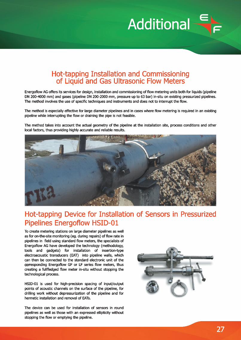
Hot-tapping Installation and Commissioning of Liquid and Gas Ultrasonic Flow Meters
Energoflow AG offers its services for design, installation and commissioning of flow metering units both for liquids (pipeline DN 200-4000 mm) and gases (pipeline DN 200-2000 mm, pressure up to 63 bar) in-situ on existing pressurized pipelines. The method involves the use of specific techniques and instruments and does not to interrupt the flow.
The method is especiaThe method is especially effective for large diameter pipelines and in cases where flow metering is required in an existing pipeline while interrupting the flow or draining the pipe is not feasible.
The method takes into account the actual geometry of the pipeline at the installation site, process conditions and other local factors, thus providing highly accurate and reliable results.
Hot-tapping Device for Installation of Sensors in Pressurized Pipelines Energoflow HSID-01To create metering stations on large diameter pipelines as well as for on-the-site monitoring (eg. during repairs) of flow rate in pipelines in field using standard flow meters, the specialists of Energoflow AG have developed the technology (methodology, tools and gadgets) for installation of insertion-type electroacoustic transducers (EAT) into pipeline walls, which can then be connected to the standard electronic unit of the corcorresponding Energoflow GF or LF series flow meters, thus creating a fullfledged flow meter in-situ without stopping the technological process.
HSID-01 is used for high-precision spacing of input/output points of acoustic channels on the surface of the pipeline, for drilling work without depressurization of the pipeline and for hermetic installation and removal of EATs.
The device can be used for installation of sensors in round pipelines as well as those with an expressed ellipticity without stopping the flow or emptying the pipeline.
27
Additional
Integrated Metering and Monitoring Systems
Green Power Solutions
Energoflow AG is dedicated to spread the idea of creating a better environment by using ecologically clean solutions.
AAll our devices can be supplied with "Green Power Solutions" - solar energy based autonomous power supply units capable of providing the full functionality of the equipment. Our engineers can also provide for such solutions for equipment supplied by other manufacturers.
Typically, such solution would comprise three major parts:1. A solar panel of the required size for converting solar energy into the requiered amount of electrical power.2.2. An accumulator battery for storing the generated power.3. An intelligent controller for smooth operation of the whole system - for regulating the power output and for monitoring the status of the solar panel, the accumulator battery as well as the ambient conditions. The controller can be equipped with a LCD screen for displaying the data. It is also possible to connect to a SCADA system via GPS/GPRS or other networks for remote monitoring of the unit.
IIn order to design such solution, the following data would generally be required:● a detailed specification of the technical characteristics of the equipment to be deployed and powered;● meteorological data on the site of installation;● facilities for mounting the solar panel.
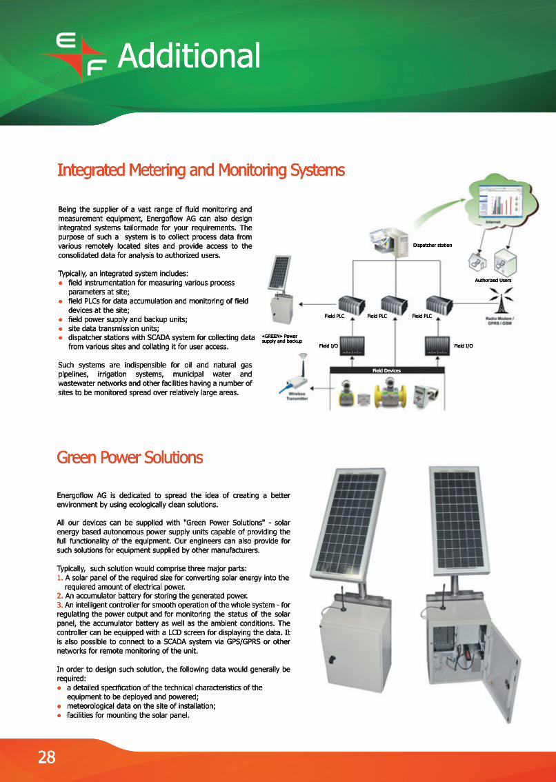
Being the supplier of a vast range of fluid monitoring and measurement equipment, Energoflow AG can also design integrated systems tailormade for your requirements. The purpose of such a system is to collect process data from various remotely located sites and provide access to the consolidated data for analysis to authorized users.
TTypically, an integrated system includes:● field instrumentation for measuring various process parameters at site;● field PLCs for data accumulation and monitoring of field devices at the site;● field power supply and backup units;● site data transmission units;●● dispatcher stations with SCADA system for collecting data from various sites and collating it for user access.
Such systems are indispensible for oil and natural gas pipelines, irrigation systems, municipal water and wastewater networks and other facilities having a number of sites to be monitored spread over relatively large areas.
28
Field PLC
«GREEN» Power supply and backup
Field PLC Field PLC
Field I/OField I/O
Dispatcher station
Authorized Users
Field Devices

Energoflow AG,Ringstrasse 28, CH-4600 Olten, Switzerland Tel: +41 62 212 8907Fax: +41 62 212 8912 [email protected]
/EnergoflowAG
/EnergoflowAG
/Energoflow-AG