Electrical Impedance Tomography for Biomedical...
6
IPASJ International Journal of Electronics & Communication (IIJEC) Web Site: http://www.ipasj.org/IIJEC/IIJEC.htm A Publisher for Research Motivation........ Email: [email protected] Volume 3, Issue 5, May 2015 ISSN 2321-5984 Volume 3, Issue 5, May 2015 Page 15 ABSTRACT In this paper design and implementation of Electrical Impedance Tomography (EIT) system has been discussed. EIT is a method that constructs the electrical impedance distribution image of the cross section of a body based on current excitation and voltage measurement from electrode array. The EIT image provides the significant physiological and pathological information according to the electrical property of the tissue inside the human body. Since the image quality heavily depends on the performance of the applied current, such as frequency, current accuracy and stability, the design of a steady and highly accurate signal source is of great significance. In EIT measurement, multi-frequency system can provide more useful information about the body tissue, so the current source of the EIT system should supply multi-frequency signal for measurement. Both real part and imaginary part of the signal from the EIT measurements contain abundant physiological and pathological information about human body. Hence, a signal source that provides accurate excitation signal for measurement and reference signal is quite important in EIT system. The impedance data is then exported to MATLAB for position correlation and post processing. In medical applications, due to the differences in bioelectrical properties between tissues, the conductivity distribution can show the structural and functional properties of the subject. Different organs of human body show a contrast in bioimpedance imaging. Further, physiological variations, such as increased blood volume in lungs, cause bioelectrical property changes which can be imaged as a varying conductivity distribution. Keywords: Electrodes, Analog multiplexer, ARM processor, Impedance converter, EIDORS. 1. INTRODUCTION Electrical Impedance Tomography (EIT) is a noninvasive medical imaging technique in which current is applied to surface of the body through contact electrodes and the resulting surface voltages are used in reconstruction of images[6][10]. An EIT is a non-invasive technique which monitors and can be used to take measure of electrical activity of the heart, measure the rate and regularity of heartbeats. It also checks the position of the chambers and identifies any damage to the heart and investigates the effect of drugs and devices used to regulate the heart. Many physiological parameters are calculated from bio impedance. Measurement device provides information about correlation between two signals by producing ECG and bio-impedance. Other physiological parameters such as oxygen saturation in hemoglobin[2], electromyography and blood pressure similarly provide vital information about the health of a given person when continuously monitored. To provide a continuous monitoring of several physiological parameters EIT system can be used[1]. This system is commonly used to detect, process and record several physiological signals simultaneously. The goal of our project is to study and develop EIT based system to produce an image of internal conductivity distribution of an object. Electrical Impedance Tomography for Biomedical Application 1 D. K. Kamat , 2 Sunil M. Shinde , 3 Dr. P. M. Patil 1 Asst Prof, Dept of E & TC, Sinhgad Academy of Engg, Pune And Research Scholar, SCOE, Pune, India 2 Dept of E & TC, Sinhgad Academy of Engg, Kondhwa, Pune, India 3 Joint Director, KJ’s Institutes Campus, Kondhwa, Pune, India
Transcript of Electrical Impedance Tomography for Biomedical...

IPASJ International Journal of Electronics & Communication (IIJEC) Web Site: http://www.ipasj.org/IIJEC/IIJEC.htm
A Publisher for Research Motivation........ Email: [email protected] Volume 3, Issue 5, May 2015 ISSN 2321-5984
Volume 3, Issue 5, May 2015 Page 15
ABSTRACT In this paper design and implementation of Electrical Impedance Tomography (EIT) system has been discussed. EIT is a method that constructs the electrical impedance distribution image of the cross section of a body based on current excitation and voltage measurement from electrode array. The EIT image provides the significant physiological and pathological information according to the electrical property of the tissue inside the human body. Since the image quality heavily depends on the performance of the applied current, such as frequency, current accuracy and stability, the design of a steady and highly accurate signal source is of great significance. In EIT measurement, multi-frequency system can provide more useful information about the body tissue, so the current source of the EIT system should supply multi-frequency signal for measurement. Both real part and imaginary part of the signal from the EIT measurements contain abundant physiological and pathological information about human body. Hence, a signal source that provides accurate excitation signal for measurement and reference signal is quite important in EIT system. The impedance data is then exported to MATLAB for position correlation and post processing. In medical applications, due to the differences in bioelectrical properties between tissues, the conductivity distribution can show the structural and functional properties of the subject. Different organs of human body show a contrast in bioimpedance imaging. Further, physiological variations, such as increased blood volume in lungs, cause bioelectrical property changes which can be imaged as a varying conductivity distribution. Keywords: Electrodes, Analog multiplexer, ARM processor, Impedance converter, EIDORS.
1. INTRODUCTION Electrical Impedance Tomography (EIT) is a noninvasive medical imaging technique in which current is applied to surface of the body through contact electrodes and the resulting surface voltages are used in reconstruction of images[6][10]. An EIT is a non-invasive technique which monitors and can be used to take measure of electrical activity of the heart, measure the rate and regularity of heartbeats. It also checks the position of the chambers and identifies any damage to the heart and investigates the effect of drugs and devices used to regulate the heart. Many physiological parameters are calculated from bio impedance. Measurement device provides information about correlation between two signals by producing ECG and bio-impedance. Other physiological parameters such as oxygen saturation in hemoglobin[2], electromyography and blood pressure similarly provide vital information about the health of a given person when continuously monitored. To provide a continuous monitoring of several physiological parameters EIT system can be used[1]. This system is commonly used to detect, process and record several physiological signals simultaneously. The goal of our project is to study and develop EIT based system to produce an image of internal conductivity distribution of an object.
Electrical Impedance Tomography for Biomedical Application
1D. K. Kamat , 2Sunil M. Shinde , 3Dr. P. M. Patil
1Asst Prof, Dept of E & TC, Sinhgad Academy of Engg, Pune And Research Scholar, SCOE, Pune, India
2Dept of E & TC, Sinhgad Academy of Engg, Kondhwa, Pune, India
3Joint Director, KJ’s Institutes Campus, Kondhwa, Pune, India

IPASJ International Journal of Electronics & Communication (IIJEC) Web Site: http://www.ipasj.org/IIJEC/IIJEC.htm
A Publisher for Research Motivation........ Email: [email protected] Volume 3, Issue 5, May 2015 ISSN 2321-5984
Volume 3, Issue 5, May 2015 Page 16
Figure 1 A methodological diagram of EIT system A method for EIT system optimizes the electronic circuit as well as a reconstruction algorithm. A methodological diagram of EIT system is shown in Figure 1. In this eight electrodes are used which are excited by using ac source with 30 kHz frequency and also with same electrodes responses are taken. Further the response signal is processed through impedance analyzer integrated circuit such that impedance values are known. Image of the object with respective to conductivity is constructed by using the values of impedance.
2. MODELED STRUCTURE OF EIT SYSTEM
EIT refers to a medical imaging technique in which an image of the conductivity or permittivity of part of the body is inferred from surface electrode measurements [11]. Electrical conductivity depends on free ion content and differs considerably between various biological tissues (absolute EIT) or different functional states of one and the same tissue or organ (relative or functional EIT). The majority of EIT systems apply small alternating currents at a single frequency, however, some EIT systems use multiple frequencies to better differentiate between normal and suspected abnormal tissue within the same organ (multi-frequency EIT or electrical impedance spectroscopy). Figure 2 shows the modeled structure of EIT system.
Figure 2 Modeled structure of EIT The AD5933 provides excitation as well as it receives response from applied excitation and convert received response into impedance which is loaded in software to construct image [7].
3. ELECTRODES Solid wire consists of multiple strand of aluminum metal wire surrounded by an insulator is used as electrode in this system. These are used as they are flexible and can be easily installed in the system. Corrosion is the unwanted breakdown and weakening of a material due to various reasons such as chemical reactions so aluminum material is used which generally resists corrosion. There could be various methods of arrangement of electrodes like one ring or more than one ring, but for this proposed EIT system only one ring of electrodes are used[5]. 4. ANALOG MULTIPLEXER The HEF4051B is an 8-channel analog multiplexer with three address inputs, an active LOW enable input and eight independent outputs. The supply voltage range is 3V to 15V. The select inputs are operated from ARM7 processor.
Electrodes
Current injection into
electrodes and
Impedance Measurement
from electrodes
Image reconstruction
in software
Impurity
PC or Laptop RS 232
ARM LPC2138
AD5933 Multiplexer
OBJECT
Electrode
IPASJ International Journal of Electronics & Communication (IIJEC) Web Site: http://www.ipasj.org/IIJEC/IIJEC.htm
A Publisher for Research Motivation........ Email: [email protected] Volume 3, Issue 5, May 2015 ISSN 2321-5984
Volume 3, Issue 5, May 2015 Page 17
5. ARM PROCESSOR In this system LPC2138 microprocessor is used. Arm processor helps to record response taken from electrodes in the form of database. The necessary codes[8] required for AD5933 IC, for making correct choice of multiplexer select inputs for sensing signal from electrodes andforRS232data transfer is set through processor. The impedance magnitude is evaluated in Visual Basic (VB) software. This software is also used for collecting impedance magnitudes in Microsoft access file.
6. AD5933 IMPEDANCE CONVERTER The developed system performs impedance measurement. The real and imaginary terms of the impedance are obtained with the help of AD5933 IC [9]. This IC is also used to set excitation voltage with different range of frequencies, for this proposed system 30 kHz of excitation source with 2V peak to peak is provided from AD5933.
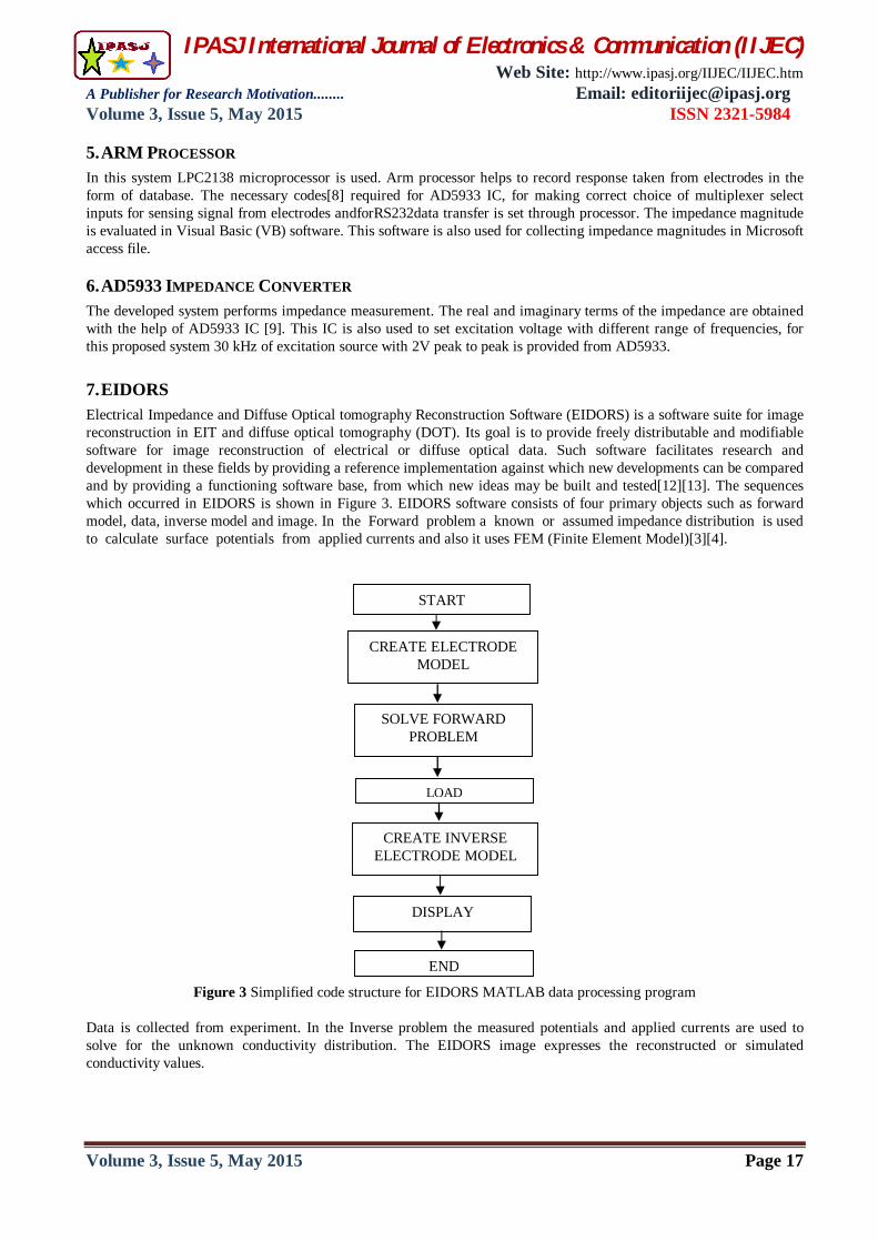
7. EIDORS Electrical Impedance and Diffuse Optical tomography Reconstruction Software (EIDORS) is a software suite for image reconstruction in EIT and diffuse optical tomography (DOT). Its goal is to provide freely distributable and modifiable software for image reconstruction of electrical or diffuse optical data. Such software facilitates research and development in these fields by providing a reference implementation against which new developments can be compared and by providing a functioning software base, from which new ideas may be built and tested[12][13]. The sequences which occurred in EIDORS is shown in Figure 3. EIDORS software consists of four primary objects such as forward model, data, inverse model and image. In the Forward problem a known or assumed impedance distribution is used to calculate surface potentials from applied currents and also it uses FEM (Finite Element Model)[3][4].
Figure 3 Simplified code structure for EIDORS MATLAB data processing program Data is collected from experiment. In the Inverse problem the measured potentials and applied currents are used to solve for the unknown conductivity distribution. The EIDORS image expresses the reconstructed or simulated conductivity values.
START
CREATE ELECTRODE MODEL
DISPLAY
SOLVE FORWARD PROBLEM
LOAD
CREATE INVERSE ELECTRODE MODEL
END

IPASJ International Journal of Electronics & Communication (IIJEC) Web Site: http://www.ipasj.org/IIJEC/IIJEC.htm
A Publisher for Research Motivation........ Email: [email protected] Volume 3, Issue 5, May 2015 ISSN 2321-5984
Volume 3, Issue 5, May 2015 Page 18
8. RESULTS
From the experimentation, the actual homogeneous medium and its reflection in the form of image construction with use of MATLAB is shown in Figure 4 and Figure 5 respectively. In Figure 6 metal rod is placed in between electrode number 5 and 6. The related plot can be seen in MATLAB as red portion as shown in Figure 7. Similarly another result can be seen as shown in Figure 8 as MATLAB image for Figure 9.
Figure 8 Saline water with object present between
electrode number 3 and 4.
Figure 9 MATLAB image plot of object between
electrode number 3 and 4.
9. SUMMARY The results and plots are obtained by applying the EIT algorithm for acquired impedance values. Results for image extraction are studied and the internal mechanism of an object is seen in terms of conductivity distribution (impedance distribution).
Figure 4 Practical pure saline water
Figure 5 MATLAB image of pure saline water
Figure 6 Saline water with object present between
electrode number 5 and 6.
Figure 7 MATLAB image plot of object between
electrode number 5 and 6.

IPASJ International Journal of Electronics & Communication (IIJEC) Web Site: http://www.ipasj.org/IIJEC/IIJEC.htm
A Publisher for Research Motivation........ Email: [email protected] Volume 3, Issue 5, May 2015 ISSN 2321-5984
Volume 3, Issue 5, May 2015 Page 19
10. CONCLUSION The results obtained from the work shows that the Electrical Impedance Tomography System fulfills all the functional specifications that motivated its design. Image reconstruction is one of the key components of the EIT technique, in which the boundary measurements are used, together with the knowledge of the boundary shape of the object, the position of the electrodes and the excitation to reconstruct the impedance distribution of the image object.
REFERENCES
[1] Sagar K. Dhar and Quazi D. Hossain, “Non-invasiveBio-impedance Measurement Using Voltage-Current PulseTechnique,” International Conference on Electrical, Electronics and Biomedical Engineering (ICEEBE'2012), Penang, Malaysia, May 2012.
[2] B.Freer and J.Venkataraman, “Feasibility study for noninvasive blood glucose monitoring,” Proceedings of IEEE Symposium (APSURSI), pp. 1-4, Sept. 2010.
[3] Ying Li1, LiyunRao, Renjie He, GuizhiXu , Qing Wu , Weili Yan, Guoya Dong and Qingxin Yang, “A Novel Combination Method of Electrical Impedance Tomography Inverse Problem for Brain Imaging,” IEEE Transactions on Magnetics, vol. 41, no. 5, May 2005.
[4] Rao L, He R, Wang Y, Yan W, Bai J. and Ye D, “An Efficient Improvement of Modified Newton-Raphson Algorithm for Electrical Impedance Tomography,” IEEE Transactions on Magnetics, vol. 35, no. 3, pp 1562-1565, May 1999.
[5] David M. Otten and Boris Rubinsky, “Monitoring Using Bioimpedance Measurements A Feasibility Study for Electrical Impedance Tomography,” IEEE Transactions on Biomedical Engineering, vol. 47, no. 10, Oct 2000.
[6] VidyaSarode, Priya M. Chimurkar and Alice N Cheeran, “Electrical Impedance Tomography using EIDORS in a Closed Phantom,” International Journal of Computer Applications, vol. 48, no.19, Jun 2012.
[7] J. Ferreiraand and F. Seoane, “AD5933-Based Electrical Bioimpedance spectrometer. Towards Textile-Enabled Applications,” 33rd Annual International Conference of the IEEE EMBS, Sept 2011.
[8] P.Blessy, R.Jegan, and X.Anitha Mary, “Seat Occupancy Detection Based on Impedance Measurement,” International Journal of Innovative Technology and Exploring Engineering, vol. 2, no. 4, Mar 2013.
[9] Melwin Abraham C and K. Rajasekaran, “Implementation of Bioimpedance Instrument Kit in ARM7,” International Journal of Advanced Research in Computer Science and Software Engineering, vol. 3, no. 5, May 2013.
[10] Vidya Sarode, Priya M. Chimurkar and Alice N. Cheeran, “Electrical Impedance Tomography (EIT) Based Medical Imaging Using Finite Element Method (FEM),” International Journal of Engineering Sciences & Emerging Technologies, Feb 2012.
[11] Deepti Gargand and Vikas Goel, “Design and development of Electrical Impedance Tomography (EIT) based System, ” International Journal of Computer Applications, vol. 74, no.7, Jul 2013.
[12] S. Grimnes and O. G. Martinsen, “Bioimpedanceand Bioelectricity Basics,” Science Direct, Second Edition Academy Press, ISBN: 978-0-12-374004-5.
[13] Eaton J W, “Gnu Octave Manual,” Network Theory Ltd, Bristol, UK, 2002. AUTHOR
Durgaprasad K. Kamat received his BE degree in the field of Electronics Engineering in 1994 from Shivaji University, Kolhapur. He has completed ME in Electronics Engineering at SCOE, affiliated to University of Pune in 2008. He is working as Assistant Professor in the Department of E & TC Engineering of Sinhgad Academy of Engineering, Pune, since 2005. His research interests are Signal Processing, Embedded Systems and Biomedical Applications. He has 10 years of teaching experience and 7 years of industry experience. Mr. Kamat is a life member of IETE. He
has published ten papers in International Journal and seven papers in International and National Conferences.
Sunil M. Shinde received his B.E. degree in Electronics and Telecommunication engineering in the year 2009, from SVERI’s College, Solapur University, Solapur. He is pursuing M.E. in Electronics and telecommunication with the specialization in VLSI and Embedded Systems, since 2011, at Sinhgad Academy of Engineering, Kondhwa, Pune, under Pune University. He has 5 years of teaching experience. His area of interest is Analog Electronics and Embedded Systems.

IPASJ International Journal of Electronics & Communication (IIJEC) Web Site: http://www.ipasj.org/IIJEC/IIJEC.htm
A Publisher for Research Motivation........ Email: [email protected] Volume 3, Issue 5, May 2015 ISSN 2321-5984
Volume 3, Issue 5, May 2015 Page 20
Dr. Pradeep Mitharam Patil received his B. E. (Electronics) degree in 1988 from Amravati University, Amravati, (India) and M. E. (Electronics) degree in 1992 from Marathwada University, Aurangabad, (India). He received his Ph.D. degree in Electronics and Computer Engineering in 2004 at Swami Ramanand Teerth Marathwada University, (India). From 1988 to 2011 he worked as Lecturer and Assistant Professor, Professor in department of Electronics Engineering at various engineering colleges in Pune University, (India). He has worked as Dean, RMD Sinhgad School of Engineering and Director of RMD Sinhgad Technical Institutes Campus,
Warje, Pune, (India). Presently he is working as Joint Director, KJ’s Institutes Campus, Kondhwa, Pune, (India). He is member of various professional bodies like IE, ISTE, IEEE and Fellow of IETE. He has been recognized as a PhD guide by various Universities in the state of Maharashtra (India). His research areas include pattern recognition, neural networks, fuzzy neural networks and power electronics. His work has been published in various international and national journals and conferences including IEEE and Elsevier.