ELCT201: Digital Logic Design - GUCeee.guc.edu.eg/Courses/Electronics/ELCT201 Digital Logic...
36
ELCT201: Digital Logic Design Lecture 7 1 Dr. Eng. Rania.Swief e-mail: [email protected] Dr. Eng. Haitham Omran e-mail: [email protected]
Transcript of ELCT201: Digital Logic Design - GUCeee.guc.edu.eg/Courses/Electronics/ELCT201 Digital Logic...

ELCT201: Digital Logic
Design Lecture 7
1
Dr. Eng. Rania.Swief e-mail: [email protected]
Dr. Eng. Haitham Omran e-mail: [email protected]
Dr. Eng. Ahmed H. Madian 2
Outlines
• Sequential Circuit
– Flip-Flop (FF) characteristic table & equations
– FF Direct input
– Finite State Machine (FSM)
– Design of FSMs
– Analysis of FSMs
Dr. Eng. Ahmed H. Madian 3
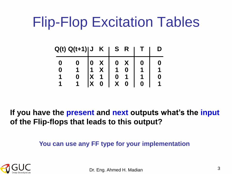
Flip-Flop Excitation Tables
Q(t+1) 0 1 0 1
Q(t) 0 0 1 1
J
0 1 X X
K
X X 1 0
S
0 1 0 X
R
X 0 1 0
T
0 1 1 0
D 0 1 0 1
You can use any FF type for your implementation
If you have the present and next outputs what’s the input
of the Flip-flops that leads to this output?

Dr. Eng. Ahmed H. Madian 4
Direct input ( Asynchronous input )
– Direct preset :
Setting the flip-flop asynchronously.
– Direct clear :
Clearing the flip-flop asynchronously.
J K
Q’ Q
CLK
Clear
Inputs Outputs
Clear CLK J K Q Q’
0 x x x 0 1
1 0 0 Q0 Q0’
1 0 1 0 1
1 1 0 1 0
1 1 1 Q0’ Q0

Dr. Eng. Ahmed H. Madian 5
NOW
• we have covered the memory elements
issue and we are ready to implement the
sequential circuits.
• We need to know how to Deal (analyze)
with a sequential circuit?

Dr. Eng. Ahmed H. Madian 6
How could you describe
combinational circuit?
• Truth table
• Logic function between input and output • F = A+B => if A= 1 and B= 0 F= 1
if A =0 and B=0 F=0 (not depends on the pervious value of F)
How could you describe a sequential circuit?
• The sequential circuit output is now function in the inputs and past outputs
• So, we need a tool to help us describe the behavior of the circuit.

Dr. Eng. Ahmed H. Madian 7
Finite State Machine (FSM)
• Finite State Machine is a tool to model the desired behavior of a
sequential system.
• The designer has to develop a finite state model of the system behavior and then designs a circuit that implements this model
• A FSM consists of several states. Inputs into the machine are combined with the current state of the machine to determine the new state or next state of the machine.
• Depending on the state of the machine, outputs are generated based on either the state or the state and inputs of the machine How to describe FSM?
– State equation ( transition equation ) input variables, present states, next states equation
– State table input variables, present states ,next states, truth table
– State diagram

FSM Example • Events:
– Wake up at fixed time every day
– Weekends: you don’t need alarm, so you wake up, turn off the alarm and resume sleep
• FSM modeling this chain of events, with: – Three states:
• Asleep
• Awake but still in bed
• Awake and up
– Inputs:
• Alarm
• Weekday (determines you how to react to alarm)
– Outputs:
• Turn off the alarm

State tables
• Similar to the truth table
• Doesn’t contain the system clock when specifying
its transitions (it is implicit that transitions occur
only when allowed by clock)
• Unless different stated, all the transitions are
occurring on the positive edge of the clock
Present
State
Inputs Next
State
Outputs

Alarm clock state table
• When you are asleep and alarm goes on, you go from being asleep to being awaked in bed; you also turn off the alarm
• The next two rows encode your actions: – You get up
– You go back to sleep
• This table doesn’t cover what you wouldn’t do…(i.e. if you are asleep and the alarm doesn't go off, you remain asleep, etc..)
Present
State
Alarm Weekday Next State Turn off alarm
Asleep On X Awake in
bed
Yes
Awake in
bed
Off Yes Awake and
up
No
Awake in
bed
Off No Asleep No

Alarm clock state table
• Covers all the cases – First row covers the situation you are asleep, the alarm
doesn’t go off and you remain asleep
– Last row covers the situation you are awake and up and you remain awake and up
– The third row covers the case you are already up and the alarm goes off. You turn it off and remain Awake in bed
Present State Alarm Weekday Next State Turn off alarm
Asleep Off X Asleep No
Asleep On X Awake in bed Yes
Awake in bed On X Awake in bed Yes
Awake in bed Off Yes Awake and up No
Awake in bed Off No Asleep No
Awake and up X X Awake and up No

State diagram
• Graphical representation of the state table
• Each state is represented by a circle vertex
• Each row of the state table is represented as a directed arc from present state vertex to the next state vertex
• In this diagram, the outputs are associated with the states
Initial State
State
0/0
Awake and up
Awake in bed Asleep
Alarm’ or Weekday/0
Alarm’/0 Input/Output
Alarm/1
Always/0
Alarm/0

Dr. Eng. Ahmed H. Madian 13
Transitions ( how it works?)
• Triggered by input events the FSM moves from one state to
other based on the Transition Function.
• Transition Function produces the Output and Next State
depending on Current State and Input Event
• While in particular state FSM is not active, it is waiting for an
input to perform next activity
Dr. Eng. Ahmed H. Madian 14
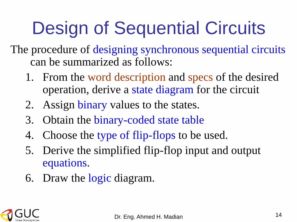
Design of Sequential Circuits The procedure of designing synchronous sequential circuits
can be summarized as follows:
1. From the word description and specs of the desired operation, derive a state diagram for the circuit
2. Assign binary values to the states.
3. Obtain the binary-coded state table
4. Choose the type of flip-flops to be used.
5. Derive the simplified flip-flop input and output equations.
6. Draw the logic diagram.

Dr. Eng. Ahmed H. Madian 15
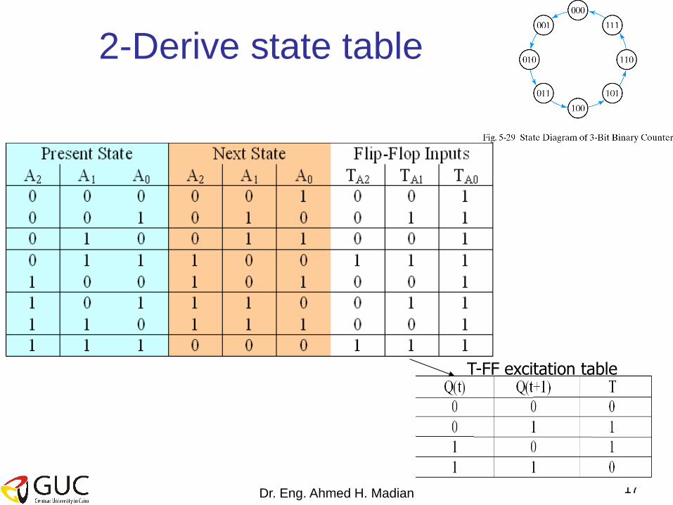
Example
• Using T-type FFs, design a 3-bits binary
counter that can count in binary from 0 to 7
with step 1

Dr. Eng. Ahmed H. Madian 16
1-Derive the state diagram
As we need a 3 binary bits to represent the numbers from 0 to
7 so we need 1 T-FF to generate 1 binary bit
We need 3 T-FF to implement this design
Dr. Eng. Ahmed H. Madian 17
2-Derive state table
T-FF excitation table

Dr. Eng. Ahmed H. Madian 18
3-K-map for the FF output equations

Dr. Eng. Ahmed H. Madian 19
Draw Circuit logic diagram

Dr. Eng. Ahmed H. Madian 20
Types of FSM systems
There are two types of sequential systems:
•Moore FSM
•Mealy FSM

Dr. Eng. Ahmed H. Madian 21
Moore FSM • Output Is a Function of a Present State Only
Present State
Register
Next State
function
Output
function
Inputs
Present State Next State
Outputs
clock reset
State
diagram state 1 /
output 1
state 2 /
output 2
transition
condition 1
transition
condition 2

Dr. Eng. Ahmed H. Madian 22
Mealy FSM • Output Is a Function of a Present State and Inputs
Next State
function
Output
function
Inputs
Present State Next State
Outputs
Present State
Register clock reset
state 1 state 2
transition condition 1
/output 1
transition condition 2
/output 2
State
diagram

In this course we will consider
only Mealy FSM
Dr. Eng. Ahmed H. Madian 23

Dr. Eng. Ahmed H. Madian 24
• Design a FSM that detects 3 or more
consecutive ones.
Design Example 2
Our system
X Y 3 ones detector

Dr. Eng. Ahmed H. Madian 25
1. Derive state diagram
S0
00
S1
01
1/0
0/0
• We will begin with assumption that no input entered to
system, we will give this state name S0
• Our system will stop at S0 if the input to the system is
always ‘0’
• If the system has ‘1’ input a new states created which
represent the state that you have only 1 we will call it S1

Dr. Eng. Ahmed H. Madian 26
• If the system was in state S1 and a ‘0’ entered the system, it must be returned to S0 as we are searching for 3 consecutive ones.
• Else if another ‘1’ entered the system it will go to new state that represent existing of two ones consecutive we will call it S2.
• If the system was in state S2 and ‘0’ entered the system it will return to S0.
• Else if ‘1’ entered to the system it will move to a new state that represent the existing of three consecutive ones S3 and the output would be equal to y=‘1’.
• If the system has more ones as an input it will continue at S3 and output y=‘1’
• Finally, if we have input X=‘0’ to the system, it will goes to the starting state S0
0/0
S0
00
S1
01
S2
10
0/0
1/0 1/0
1/1 S3
11
0/0 0/0
1/1

Dr. Eng. Ahmed H. Madian 27
Present State
Input Next State
Out FF Inputs
A B X A B y DA DB
0 0 0 0 0 0 0 0
0 0 1 0 1 0 0 1
0 1 0 0 0 0 0 0
0 1 1 1 0 0 1 0
1 0 0 0 0 0 0 0
1 0 1 1 1 1 1 1
1 1 0 0 0 0 0 0
1 1 1 1 1 1 1 1
2. Construct the state table
Q(t) Q(t+1) D
0 0 0
0 1 1
1 0 0
1 1 1
D–FF Excitation Table

Dr. Eng. Ahmed H. Madian 28
7. Drive simplified State Equations
Note: Output here depends on the present
state (A(t)) and input (x)

Dr. Eng. Ahmed H. Madian 29
8: Implement the FSM
Dr. Eng. Ahmed H. Madian 30
FSM Circuit Analysis • Start with schematic diagram
• Need to determine how circuit works
– Trace schematic, determine equations of operation
• FF input equations
• sequential circuit output equations
– Create State transition table
• Sequential circuit inputs, FFs are comb. logic inputs
• Organize truth table as current state (FFs) and inputs
• Create FF input, seq. Circuit output columns
• From FF char. Tables, determine FF next state values
Dr. Eng. Ahmed H. Madian 31
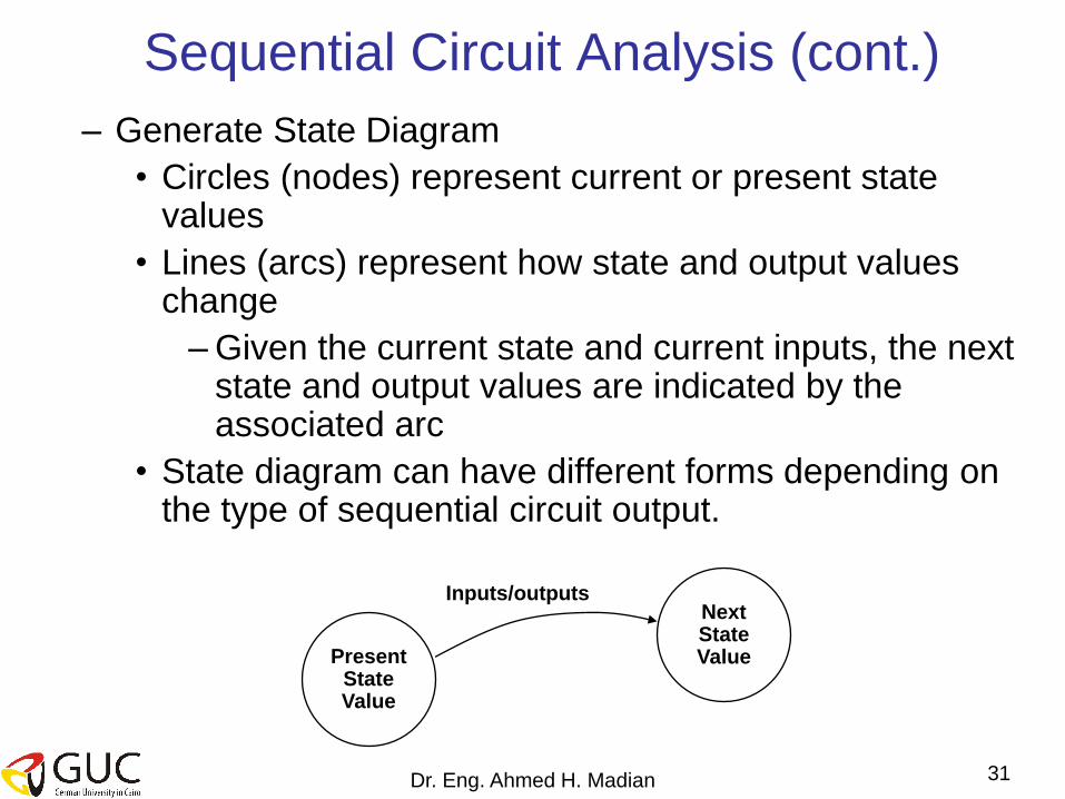
Sequential Circuit Analysis (cont.)
– Generate State Diagram
• Circles (nodes) represent current or present state values
• Lines (arcs) represent how state and output values change
– Given the current state and current inputs, the next state and output values are indicated by the associated arc
• State diagram can have different forms depending on the type of sequential circuit output.
Present State Value
Next State Value
Inputs/outputs

Dr. Eng. Ahmed H. Madian 32
Example 3
• Analyze the following sequential circuit
• How to analyze any sequential circuit
• You need to know : – State equation
– State diagram
– State table

Dr. Eng. Ahmed H. Madian 33
1- Determine State equation
• From the circuit get the logic equations of the input of flip-flops A(t+1) & B(t+1) and output y(t)
• FF input equations
A(t+1) = A(t)X(t)+B(t)X(t)
B(t+1) = A’(t)X(t)
• Output equation
Y(t) = X’(t)(B(t)+A(t))
A(t+1)
B(t+1)
(t)
(t)
(t)

Dr. Eng. Ahmed H. Madian 34
2-Create State table
• From logic equation & characteristics table of flip-flop create State table
• FF input equations
A(t+1) = AX+BX
B(t+1) = A’X
• Output equation
Y = X’(B+A)
• D flip-flop
characteristic table

Dr. Eng. Ahmed H. Madian 35
3-Construct the state diagram
00 10
01 11
0/0
Input/Output
1/0 0/1
1/0
0/1 1/0
0/1 1/0

Dr. Eng. Ahmed H. Madian 36
Please check the website for
assignment 2