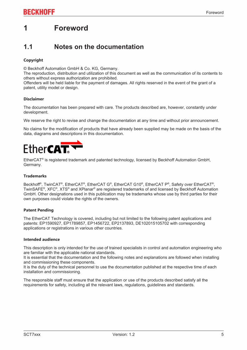
Documentation Busbar split-core current transformers
48
Documentation | EN SCT7xxx Busbar split-core current transformers 2021-04-12 | Version: 1.2
Transcript of Documentation Busbar split-core current transformers
Documentation | EN
SCT7xxxBusbar split-core current transformers
2021-04-12 | Version: 1.2

Table of contents
SCT7xxx 3Version: 1.2
Table of contents1 Foreword .................................................................................................................................................... 5
1.1 Notes on the documentation.............................................................................................................. 51.2 Safety instructions ............................................................................................................................. 6
2 Product overview....................................................................................................................................... 82.1 Introduction........................................................................................................................................ 82.2 Basics current transformers............................................................................................................... 92.3 Product categories – SCTxxxx current transformer......................................................................... 122.4 Notes on class accuracy SCT transformers .................................................................................... 20
3 Technical data.......................................................................................................................................... 213.1 SCT71xx | Busbar split-core current transformers, size 1 ............................................................... 21
3.1.1 SCT71xx | General .......................................................................................................... 213.1.2 SCT7105 | Busbar split-core current transformer for primary currents 0…100 A/0…200 A,
accuracy class 3, size 1................................................................................................... 233.1.3 SCT7115 | Busbar split-core current transformer for primary current 0...250 V / 0…400 A,
accuracy class 1, size 1................................................................................................... 243.1.4 SCT7125 | Busbar split-core current transformer for primary current 0…400 A, accuracy
class 0.5, size 1 ............................................................................................................... 253.2 SCT72xx | Busbar split-core current transformers, size 2 ............................................................... 26
3.2.1 SCT72xx | General .......................................................................................................... 263.2.2 SCT7215 | Busbar split-core current transformer for primary currents 0…500/0…600 A,
accuracy class 1, size 2................................................................................................... 283.2.3 SCT7225 | Busbar split-core current transformer for primary currents 0…500/0…600 A,
accuracy class 0.5, size 2................................................................................................ 293.3 SCT73xx | Busbar split-core current transformers, size 3 ............................................................... 30
3.3.1 SCT73xx | General .......................................................................................................... 303.3.2 SCT7315 | Busbar split-core current transformer for primary currents 0…750 to 0...1500
A, accuracy class 1, size 3 .............................................................................................. 323.3.3 SCT7325 | Busbar split-core current transformer for primary currents 0…750 to 0...1500
A, accuracy class 0.5, size 3 ........................................................................................... 333.4 SCT74xx | Busbar split-core current transformers, size 4 ............................................................... 34
3.4.1 SCT74xx | General .......................................................................................................... 343.4.2 SCT7415 | Busbar split-core current transformer for primary currents 0…1500 to 0…5000
A, accuracy class 1, size 4 .............................................................................................. 363.4.3 SCT7425 | Busbar split-core current transformer for primary currents 0...1500 to 0...5000
A, accuracy class 0.5, size 4 ........................................................................................... 37
4 Commissioning........................................................................................................................................ 384.1 Installation ....................................................................................................................................... 384.2 Maintenance and inspection............................................................................................................ 414.3 Troubleshooting............................................................................................................................... 42
5 Application example................................................................................................................................ 435.1 Power measurement at a machine.................................................................................................. 43
6 Appendix .................................................................................................................................................. 456.1 Documentation issue status ............................................................................................................ 456.2 Support and Service ........................................................................................................................ 46

Table of contents
SCT7xxx4 Version: 1.2
Foreword
SCT7xxx 5Version: 1.2
1 Foreword
1.1 Notes on the documentation
Copyright
© Beckhoff Automation GmbH & Co. KG, Germany.The reproduction, distribution and utilization of this document as well as the communication of its contents toothers without express authorization are prohibited.Offenders will be held liable for the payment of damages. All rights reserved in the event of the grant of apatent, utility model or design.
Disclaimer
The documentation has been prepared with care. The products described are, however, constantly underdevelopment.
We reserve the right to revise and change the documentation at any time and without prior announcement.
No claims for the modification of products that have already been supplied may be made on the basis of thedata, diagrams and descriptions in this documentation.
EtherCAT® is registered trademark and patented technology, licensed by Beckhoff Automation GmbH,Germany.
Trademarks
Beckhoff®, TwinCAT®, EtherCAT®, EtherCAT G®, EtherCAT G10®, EtherCAT P®, Safety over EtherCAT®,TwinSAFE®, XFC®, XTS® and XPlanar® are registered trademarks of and licensed by Beckhoff AutomationGmbH. Other designations used in this publication may be trademarks whose use by third parties for theirown purposes could violate the rights of the owners.
Patent Pending
The EtherCAT Technology is covered, including but not limited to the following patent applications andpatents: EP1590927, EP1789857, EP1456722, EP2137893, DE102015105702 with correspondingapplications or registrations in various other countries.
Intended audience
This description is only intended for the use of trained specialists in control and automation engineering whoare familiar with the applicable national standards.It is essential that the documentation and the following notes and explanations are followed when installingand commissioning these components.It is the duty of the technical personnel to use the documentation published at the respective time of eachinstallation and commissioning.
The responsible staff must ensure that the application or use of the products described satisfy all therequirements for safety, including all the relevant laws, regulations, guidelines and standards.
Foreword
SCT7xxx6 Version: 1.2
1.2 Safety instructions
Description of instructions
In this documentation the following instructions are used. These instructions must be read carefully and followed without fail!
DANGERSerious risk of injury!Failure to follow this safety instruction directly endangers the life and health of persons.
WARNINGRisk of injury!Failure to follow this safety instruction endangers the life and health of persons.
CAUTIONPersonal injuries!Failure to follow this safety instruction can lead to injuries to persons.
NOTEDamage to environment/equipment or data lossFailure to follow this instruction can lead to environmental damage, equipment damage or data loss.
Tip or pointerThis symbol indicates information that contributes to better understanding.
Exclusion of liability
All the components are supplied in particular hardware and software configurations appropriate for theapplication. Modifications to hardware or software configurations other than those described in thedocumentation are not permitted, and nullify the liability of Beckhoff Automation GmbH & Co. KG.
Personnel qualification
This description is only intended for trained specialists in control, automation and drive engineering who arefamiliar with the applicable national standards.
Intended use
If the equipment is used in a manner not specified by the manufacturer, the protection provided by theequipment may be impaired
Safety regulations
Please note the following safety instructions and explanations!Product-specific safety instructions can be found on following pages or in the areas mounting, wiring,commissioning etc.
Current transformer safety instructions
The following points must be noted:
• The applicable laws, standards and regulations.• The state of the art at the time of installation.• The technical rules.
Foreword
SCT7xxx 7Version: 1.2
• The operating instructions.• The fact that operating instructions can only list general regulations and that these regulations must be
followed.• Check the device carefully for transport damage prior to commissioning. The device must not be put
into operation if it is mechanically damaged.• The devices described are intended for installation by qualified electricians and may only be installed in
electrical plant rooms or in closed housings. Any other use or the disregard of these application noteswill result in the loss of the warranty/guarantee.
• The devices may only be installed in dry indoor rooms.• Do not mount on highly flammable materials.• Operation with a higher current than the rated current specified on the name plate can lead to
overheating of the current transformer and thus to burns.
Product overview
SCT7xxx8 Version: 1.2
2 Product overview
2.1 Introduction
SCTxxxx | Current transformers (CT) for energy measurement
Fig. 1: SCT current transformers
With its SCT current transformers, Beckhoff makes it possible to implement reliable power sensor technologyin the field, which is directly integrated into the PC-based control system. Users can select from two deviceconcepts, each with various designs and performance categories that are highly scalable and thereforesuitable for any application. The SCT portfolio is extremely broad-based, ranging from low-cost 3-phase CTsets for building technology to standard industrial transformers for machines through to solutions forinspection and test stands with extra-high accuracy requirements.
The choice of the suitable product category [} 12] depends on the type of use. While ring-type CTs arepredestined for cost-effective and accurate data acquisition in new installations, split-core CTs provide theideal solution for retrofit solutions due to their easy installation.
Product overview
SCT7xxx 9Version: 1.2
2.2 Basics current transformers
Function and design
A current transformer is a transforming device that transforms an input current into a processable currentsignal at the output. A current transformer is mainly used to transform currents of large magnitudes to directlymeasurable, smaller values in the milliampere or small ampere range. With a classic current transformer, theinput current is proportional to the output current. Due to the physical principle and the mechanicalconstruction, the current signal is transmitted galvanically isolated to the evaluation electronics.
A current transformer basically consists of a small number of windings on the primary side and a largernumber of windings on the secondary side. The current to be converted flows through the primary side. Thewindings are usually wound on an alternating magnetic ferrite ring core.
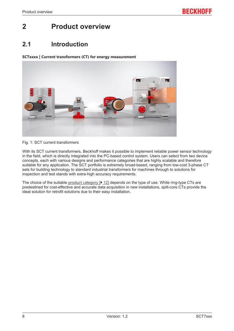
A typical transformer type is the ring core or ring-type current transformer. The current rail or current-carryingcable is often used as the primary winding, which is guided through the toroidal core of the transformer.Thus, the rail or line forms the primary winding with one turn. The secondary winding is located on the ringcore. The transformation is determined by the ratio of the number of primary and secondary windings. Theclassic structure of a ring-type current transformer is shown in the following figure.
Fig. 2: Principle ring-type current transformer
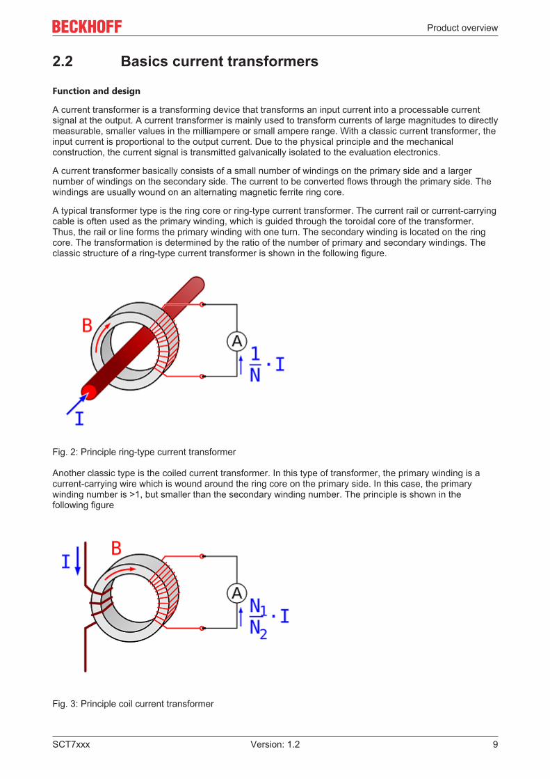
Another classic type is the coiled current transformer. In this type of transformer, the primary winding is acurrent-carrying wire which is wound around the ring core on the primary side. In this case, the primarywinding number is >1, but smaller than the secondary winding number. The principle is shown in thefollowing figure
Fig. 3: Principle coil current transformer
Product overview
SCT7xxx10 Version: 1.2
WARNINGDangerous voltages with secondary side not connectedThe secondary winding must be connected to a current measuring device or short-circuited, otherwise highcore losses or dangerous voltages may occur on the secondary side. Before replacing the measuring elec-tronics in the secondary circuit, the current transformer must therefore be short-circuited at its secondaryterminals.
Grounding of secondary terminalsAccording to DIN VDE 0141 (01/2000) paragraph 5.3.4, current and voltage transformers for nomi-nal voltages from Um = 3.6 kV must be grounded on the secondary side. For low voltages (Um ≤1.2 kV), grounding is not required if the transformer housings do not have any metal surfaces withlarge contact areas.
Characteristic values and calculation
In principle, the construction, and thus also the calculation, correspond to a normal transformer. The basicrelationship between input and output current is determined by the ratio of the number of turns N of theprimary and secondary sides. An important characteristic value in the design of a current transformer istherefore the transformer ratio.
IOut = N1/N2 * IIn
Product overview
SCT7xxx 11Version: 1.2
Technical terms of current transformers
Term ExplanationPrimary rated current Ipr (alternative formula symbol IN)
Value of the rated current on the primary side.
Secondary rated current Isr Value of the rated current on the secondary side.Rated power Sr Value of apparent power (in [VA]) that the transformer can deliver
to the secondary circuit at secondary rated current and rated load.Rated frequency fR Value of the rated frequency.Accuracy class Indication that the measurement deviations are within specified
limits under prescribed application conditions.Rated insulation level Um Maximum voltage; RMS value of the highest conductor-to-
conductor voltage for which a instrument transformer is rated withrespect to its insulation.Specified is the value of the rated insulation level in three values:1. maximum value of the conductor-to-conductor voltage for whichthe isolation of the transducers is rated;2. value of the rated AC voltage (50 Hz, 1 min) with which theinsulation safety of the equipment is tested3. value of the surge voltage level (this specification is mostlyunoccupied here, since IEC 61869/1 only requires a specificationfor transformers with a conductor-to-conductor voltage of >1.2 kV)
Overcurrent limiting factor (FS) Ratio of the rated limiting current to the primary rated current.Thermal rated continuous current Icth Value of the continuous current in the primary winding at which the
overtemperature does not exceed the value specified in thestandard, with the secondary winding loaded with the rated load.
Rated short-time thermal current Ith Value of short-time current for a limited time in the primary windingat which the excess temperature does not exceed the valuespecified in the standard, with the secondary winding loaded withthe rated load.
Rated impulse current Idyn Maximum value of the primary current, the electromagnetic forceeffect of which does not cause any electrical and mechanicaldamage to the current transformer with short-circuited secondarywinding.
“Open voltage" ofcurrent transformers
Current transformers which are not directly connected to a loadmust be short-circuited on the secondary side for safety reasons!A current transformer operated open on the secondary side inducesvery high peak voltage values at its secondary terminals. Themagnitudes of these voltages can reach values of up to severalkilovolts, depending on the dimensioning of the current transformer,and thus represent a danger to persons and the functional safety ofthe transformer. For safety reasons, and to avoid magnetization ofthe core iron during secondary-side open operation, open operationshould generally be avoided.
Grounding of secondary terminals According to DIN VDE 0141 (01/2000) paragraph 5.3.4, current andvoltage transformers for nominal voltages from Um = 3.6 kV mustbe grounded on the secondary side. For low voltages (Um ≤ 1.2kV), grounding is not required if the transformer housings do nothave any metal surfaces with large contact areas.
Product overview
SCT7xxx12 Version: 1.2
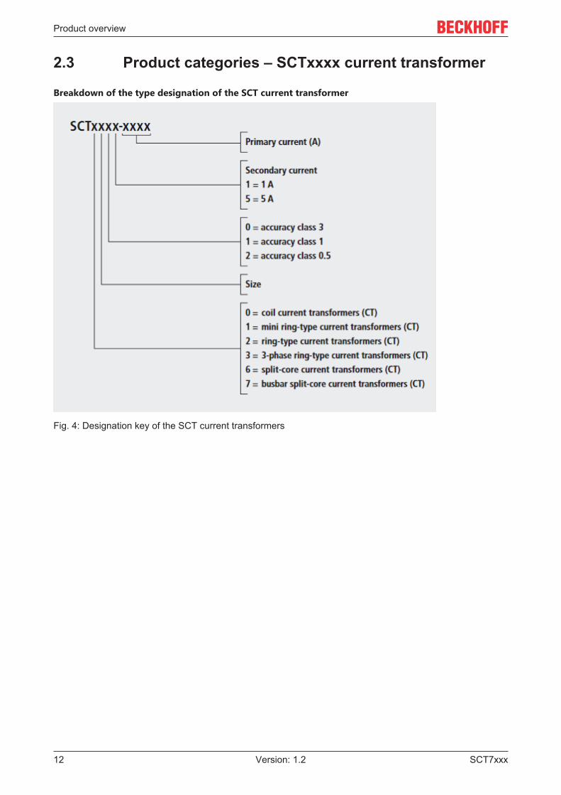
2.3 Product categories – SCTxxxx current transformer
Breakdown of the type designation of the SCT current transformer
Fig. 4: Designation key of the SCT current transformers
Product overview
SCT7xxx 13Version: 1.2
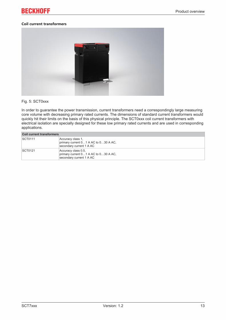
Coil current transformers
Fig. 5: SCT0xxx
In order to guarantee the power transmission, current transformers need a correspondingly large measuringcore volume with decreasing primary rated currents. The dimensions of standard current transformers wouldquickly hit their limits on the basis of this physical principle. The SCT0xxx coil current transformers withelectrical isolation are specially designed for these low primary rated currents and are used in correspondingapplications.Coil current transformersSCT0111 Accuracy class 1,
primary current 0…1 A AC to 0…30 A AC,secondary current 1 A AC
SCT0121 Accuracy class 0.5,primary current 0…1 A AC to 0…30 A AC,secondary current 1 A AC
Product overview
SCT7xxx14 Version: 1.2
Mini ring-type current transformer
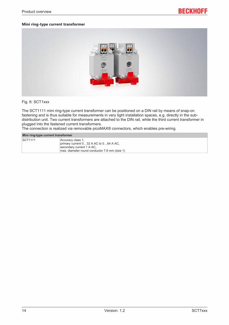
Fig. 6: SCT1xxx
The SCT1111 mini ring-type current transformer can be positioned on a DIN rail by means of snap-onfastening and is thus suitable for measurements in very tight installation spaces, e.g. directly in the sub-distribution unit. Two current transformers are attached to the DIN rail, while the third current transformer inplugged into the fastened current transformers.The connection is realized via removable picoMAX® connectors, which enables pre-wiring.Mini ring-type current transformerSCT1111 Accuracy class 1,
primary current 0…32 A AC to 0…64 A AC,secondary current 1 A AC,max. diameter round conductor 7.6 mm (size 1)
Product overview
SCT7xxx 15Version: 1.2
Ring-type current transformer
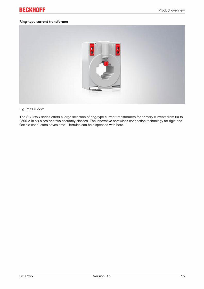
Fig. 7: SCT2xxx
The SCT2xxx series offers a large selection of ring-type current transformers for primary currents from 60 to2500 A in six sizes and two accuracy classes. The innovative screwless connection technology for rigid andflexible conductors saves time – ferrules can be dispensed with here.

Product overview
SCT7xxx16 Version: 1.2
Ring-type current transformerSCT2111 Accuracy class 1,
primary current 0…60 A AC to 0…500 A AC,secondary current 1 A AC,max. diameter round conductor 25.7 mm (size 1)
SCT2121 Accuracy class 0.5,primary current 0…125 A AC to 0…600 A AC,secondary current 1 A AC,max. diameter round conductor 25.7 mm (size 1)
SCT2211 Accuracy class 1,primary current 0…600 A AC / 0…750 A AC,secondary current 1 A AC,max. diameter round conductor 31.8 mm (size 2)
SCT2221 Accuracy class 0.5,primary current 0…600 A AC / 0…750 A AC,secondary current 1 A AC,max. diameter round conductor 31.8 mm (size 2)
SCT2311 Accuracy class 1,primary current 0…800 A AC / 0…1000 A AC,secondary current 1 A AC,max. diameter round conductor 43.7 mm (size 3)
SCT2321 Accuracy class 0.5,primary current 0…800 A AC / 1000 A AC,secondary current 1 A AC,max. diameter round conductor 43.7 mm (size 3)
SCT2411 Accuracy class 1,primary current 0…1250 A AC / 0…1500 A AC,secondary current 1 A AC,max. diameter round conductor 43.7 mm (size 4)
SCT2421 Accuracy class 0.5,primary current 0…1250 A AC / 0…1500 A AC,secondary current 1 A AC,max. diameter round conductor 43.7 mm (size 4)
SCT2515 Accuracy class 1,primary current 0…2000 A AC,secondary current 5 A AC,max. diameter round conductor 54.7 mm (size 5)
SCT2525 Accuracy class 0.5,primary current 0…2000 A AC,secondary current 5 A AC,max. diameter round conductor 54.7 mm (size 5)
SCT2615 Accuracy class 1,primary current 0…2500 A AC,secondary current 5 A AC,max. diameter round conductor 70 mm (size 6)
SCT2625 Accuracy class 0.5,primary current 0…2500 A AC,secondary current 5 A AC,max. diameter round conductor 70 mm (size 6)
Product overview
SCT7xxx 17Version: 1.2
3-phase ring-type current transformers
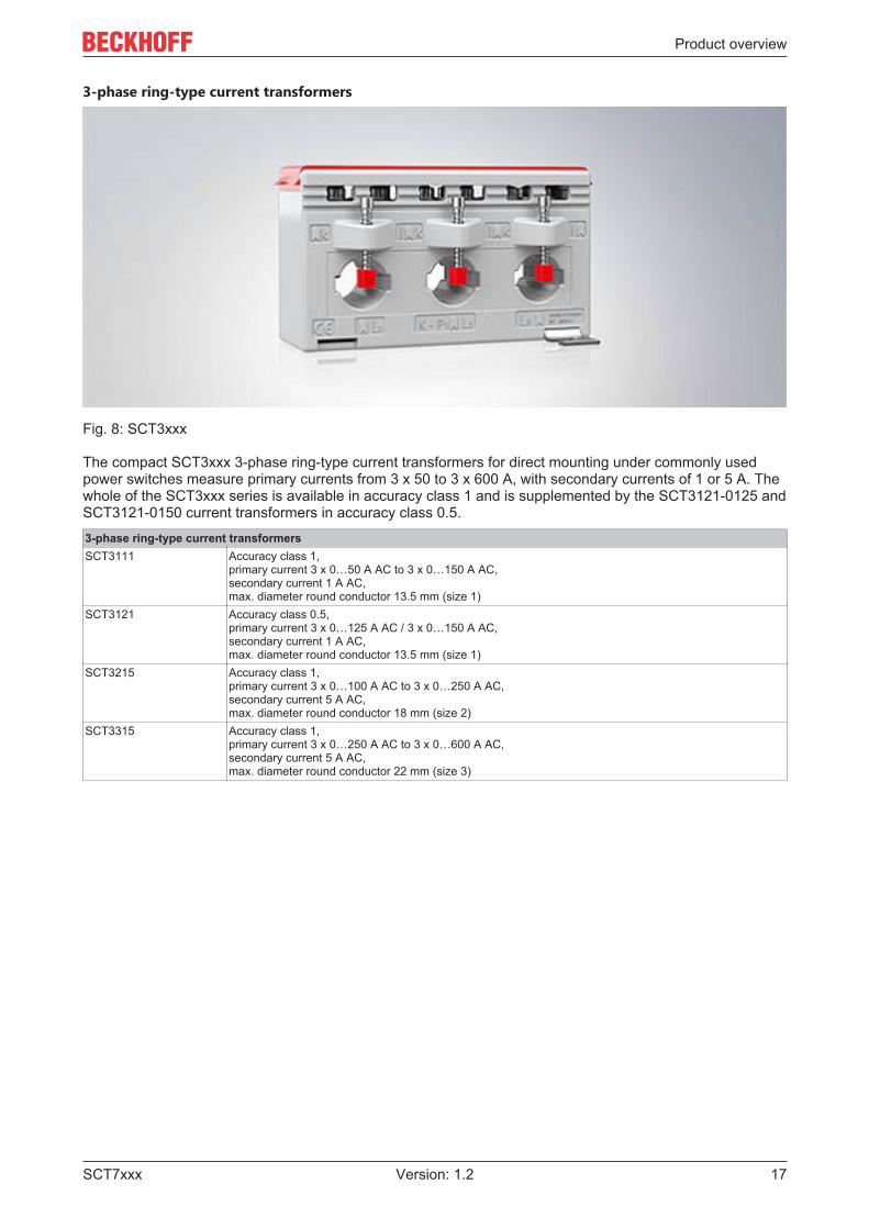
Fig. 8: SCT3xxx
The compact SCT3xxx 3-phase ring-type current transformers for direct mounting under commonly usedpower switches measure primary currents from 3 x 50 to 3 x 600 A, with secondary currents of 1 or 5 A. Thewhole of the SCT3xxx series is available in accuracy class 1 and is supplemented by the SCT3121-0125 andSCT3121-0150 current transformers in accuracy class 0.5.3-phase ring-type current transformersSCT3111 Accuracy class 1,
primary current 3 x 0…50 A AC to 3 x 0…150 A AC,secondary current 1 A AC,max. diameter round conductor 13.5 mm (size 1)
SCT3121 Accuracy class 0.5,primary current 3 x 0…125 A AC / 3 x 0…150 A AC,secondary current 1 A AC,max. diameter round conductor 13.5 mm (size 1)
SCT3215 Accuracy class 1,primary current 3 x 0…100 A AC to 3 x 0…250 A AC,secondary current 5 A AC,max. diameter round conductor 18 mm (size 2)
SCT3315 Accuracy class 1,primary current 3 x 0…250 A AC to 3 x 0…600 A AC,secondary current 5 A AC,max. diameter round conductor 22 mm (size 3)
Product overview
SCT7xxx18 Version: 1.2
Split-core current transformers
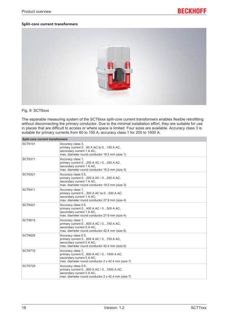
Fig. 9: SCT6xxx
The separable measuring system of the SCT6xxx split-core current transformers enables flexible retrofittingwithout disconnecting the primary conductor. Due to the minimal installation effort, they are suitable for usein places that are difficult to access or where space is limited. Four sizes are available. Accuracy class 3 issuitable for primary currents from 60 to 150 A, accuracy class 1 for 200 to 1000 A.Split-core current transformersSCT6101 Accuracy class 3,
primary current 0…60 A AC to 0…150 A AC,secondary current 1 A AC,max. diameter round conductor 18.5 mm (size 1)
SCT6311 Accuracy class 1,primary current 0…200 A AC / 0…250 A AC,secondary current 1 A AC,max. diameter round conductor 18.5 mm (size 3)
SCT6321 Accuracy class 0.5,primary current 0…200 A AC / 0…250 A AC,secondary current 1 A AC,max. diameter round conductor 18.5 mm (size 3)
SCT6411 Accuracy class 1,primary current 0…300 A AC to 0…500 A AC,secondary current 1 A AC,max. diameter round conductor 27.9 mm (size 4)
SCT6421 Accuracy class 0.5,primary current 0…400 A AC / 0…500 A AC,secondary current 1 A AC,max. diameter round conductor 27.9 mm (size 4)
SCT6615 Accuracy class 1,primary current 0…600 A AC / 0…750 A AC,secondary current 5 A AC,max. diameter round conductor 42.4 mm (size 6)
SCT6625 Accuracy class 0.5,primary current 0…600 A AC / 0…750 A AC,secondary current 5 A AC,max. diameter round conductor 42.4 mm (size 6)
SCT6715 Accuracy class 1,primary current 0…800 A AC / 0…1000 A AC,secondary current 5 A AC,max. diameter round conductor 2 x 42.4 mm (size 7)
SCT6725 Accuracy class 0.5,primary current 0…800 A AC / 0…1000 A AC,secondary current 5 A AC,max. diameter round conductor 2 x 42.4 mm (size 7)
Product overview
SCT7xxx 19Version: 1.2
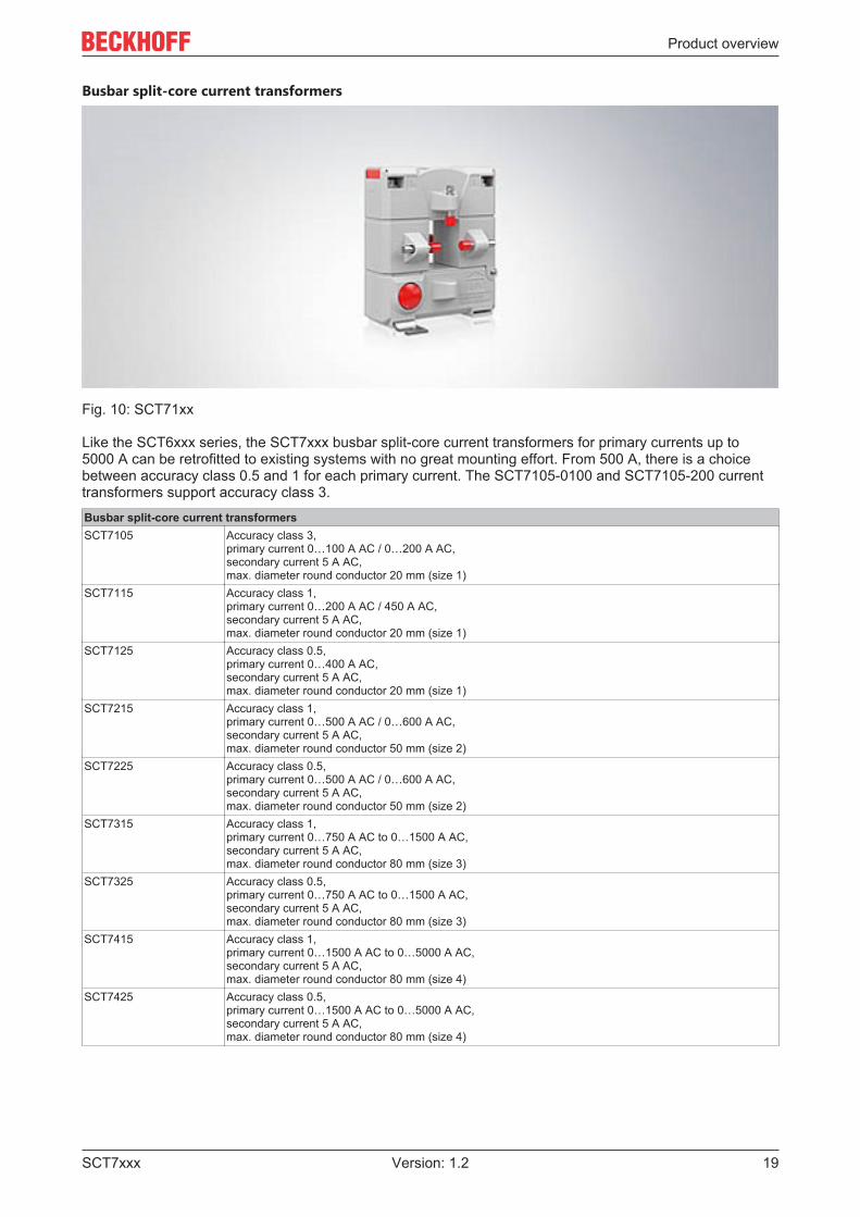
Busbar split-core current transformers
Fig. 10: SCT71xx
Like the SCT6xxx series, the SCT7xxx busbar split-core current transformers for primary currents up to5000 A can be retrofitted to existing systems with no great mounting effort. From 500 A, there is a choicebetween accuracy class 0.5 and 1 for each primary current. The SCT7105-0100 and SCT7105-200 currenttransformers support accuracy class 3.Busbar split-core current transformersSCT7105 Accuracy class 3,
primary current 0…100 A AC / 0…200 A AC,secondary current 5 A AC,max. diameter round conductor 20 mm (size 1)
SCT7115 Accuracy class 1,primary current 0…200 A AC / 450 A AC,secondary current 5 A AC,max. diameter round conductor 20 mm (size 1)
SCT7125 Accuracy class 0.5,primary current 0…400 A AC,secondary current 5 A AC,max. diameter round conductor 20 mm (size 1)
SCT7215 Accuracy class 1,primary current 0…500 A AC / 0…600 A AC,secondary current 5 A AC,max. diameter round conductor 50 mm (size 2)
SCT7225 Accuracy class 0.5,primary current 0…500 A AC / 0…600 A AC,secondary current 5 A AC,max. diameter round conductor 50 mm (size 2)
SCT7315 Accuracy class 1,primary current 0…750 A AC to 0…1500 A AC,secondary current 5 A AC,max. diameter round conductor 80 mm (size 3)
SCT7325 Accuracy class 0.5,primary current 0…750 A AC to 0…1500 A AC,secondary current 5 A AC,max. diameter round conductor 80 mm (size 3)
SCT7415 Accuracy class 1,primary current 0…1500 A AC to 0…5000 A AC,secondary current 5 A AC,max. diameter round conductor 80 mm (size 4)
SCT7425 Accuracy class 0.5,primary current 0…1500 A AC to 0…5000 A AC,secondary current 5 A AC,max. diameter round conductor 80 mm (size 4)

Product overview
SCT7xxx20 Version: 1.2
2.4 Notes on class accuracy SCT transformersCurrent transformers are divided into classes according to their accuracy. The Beckhoff SCT currenttransformers are available in the standard accuracy classes 0.5; 1 and 3, depending on the productcategory. The class designation corresponds to an error curve with regard to current amplitude and angularerror. Beckhoff SCT current transformers conform to the IEC 61869 standard.
The accuracy classes of current transformers are related to the rated current. If current transformers areoperated with a current that is low in relation to the rated current, the measuring accuracy decreases. Thefollowing tables show the fault limit values taking into account the rated current values:Class accuracy Current error (±) in % at % of rated current
5 % 20 % 50 % 100 % 120 %0,5 1,5 % 0,75 % - 0,5 % 0,5 %1 3,0 % 1,5 % - 1,0 % 1,0 %3 - - 3 % - 3 %
Class accuracy Phase shift/error angle (±) at % of rated currentAngular minutes [ ´ ] Radians [rad]
5 % 20 % 50 % 100 % 120 % 5 % 20 % 50 % 100 % 120 %0,5 90‘ 45‘ - 30‘ 30‘ 2,7 rad 1,35 rad - 0,9 rad 0,9 rad1 180‘ 90‘ - 60‘ 60‘ 5,4 rad 2,7 rad - 1,8 rad 1,8 rad3 - - - - - - - - - -
Fig. 11: Characteristic curves accuracy classes/primary current
Adjusting the transducer ratingIn order to use the optimum accuracy of the transducer, you must ensure a suitable transducer rat-ing in your application through the wiring between the transducer and the measuring terminal. Thisis done by using 0.25 to 1.0 times the rated power of the transducer.Additional resistors in the secondary path can be used to match the transducer and measuring ter-minal to each other.
Technical data
SCT7xxx 21Version: 1.2
3 Technical data
3.1 SCT71xx | Busbar split-core current transformers,size 1
3.1.1 SCT71xx | GeneralPrimary side SCT71xx-xxxxThermal rated continuous current Icth 1,0 * IN
Rated short-time thermal current Ith 60 * IN/1 s (max. 100 kA)Rated impulse current Idyn 2,5 * Ith
Rated frequency fR 50..60 Hz
Secondary side SCT71xx-xxxxSecondary rated current Isr 5 AOvercurrent limiting factor FS5
Operating conditions SCT71xx-xxxxPermissible ambient temperature range duringoperation
-5…+40 °C
Permissible ambient temperature range duringstorage
-25 … +70 °C
Permissible relative humidi 5 … 85 %Operating height Up to 1000 mProtection class IP20
Insulation characteristics SCT71xx-xxxxRated insulation level Um 0,72/3/- kVInsulation class E
Gerneral data SCT71xx-xxxxMax. Diameter conductor bushing primary conductor 20 mm x 30 mmConnection technology secondary Screw terminals M5x8Conductor cross section secondary 4 mm² with ferrule
6 mm² massiveSize 1Dimensions (W x H x D) 93 mm x 106 mm x 58 mmWeight 580 g
Standards and regulations SCT71xx-xxxxApprovals/Markings CEStandards/Regulations EN 61869-1; EN 61869-2; IEC 61010-1
Technical data
SCT7xxx22 Version: 1.2
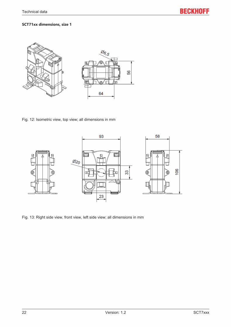
SCT71xx dimensions, size 1
Fig. 12: Isometric view, top view; all dimensions in mm
Fig. 13: Right side view, front view, left side view; all dimensions in mm

Technical data
SCT7xxx 23Version: 1.2
3.1.2 SCT7105 | Busbar split-core current transformer for primarycurrents 0…100 A/0…200 A, accuracy class 3, size 1
Technical data SCT7105-xxxxAccuracy class 3Primary current 0…100 A AC / 0…200 A ACSecondary current 5 A AC
VersionsSCT7105-0100 ratio 100/5,
rated power 1.25 VASCT7105-0200 ratio 200/5,
rated power 2.5 VA
Technical data
SCT7xxx24 Version: 1.2
3.1.3 SCT7115 | Busbar split-core current transformer for primarycurrent 0...250 V / 0…400 A, accuracy class 1, size 1
Technical data SCT7115-xxxxAccuracy class 1Primary current 0…200 A AC / 0…400 A ACSecondary current 5 A AC
VersionsSCT7115-0250 ratio 250/5,
rated power 1.5 VASCT7115-0400 ratio 400/5,
rated power 5 VA
Technical data
SCT7xxx 25Version: 1.2
3.1.4 SCT7125 | Busbar split-core current transformer for primarycurrent 0…400 A, accuracy class 0.5, size 1
Technical data SCT7125-xxxxAccuracy class 0.5Primary current 0…400 A ACSecondary current 5 A AC
VersionsSCT7125-0400 ratio 400/5,
rated power 1.0 VA
Technical data
SCT7xxx26 Version: 1.2
3.2 SCT72xx | Busbar split-core current transformers,size 2
3.2.1 SCT72xx | GeneralPrimary side SCT72xx-xxxxThermal rated continuous current Icth 1,0 * IN
Rated short-time thermal current Ith 60 * IN/1 s (max. 100 kA)Rated impulse current Idyn 2,5 * Ith
Rated frequency fR 50..60 Hz
Secondary side SCT72xx-xxxxSecondary rated current Isr 5 AOvercurrent limiting factor FS5
Operating conditions SCT72xx-xxxxPermissible ambient temperature range duringoperation
-5…+40 °C
Permissible ambient temperature range duringstorage
-25 … +70 °C
Permissible relative humidi 5 … 85 %Operating height Up to 1000 mProtection class IP20
Insulation characteristics SCT72xx-xxxxRated insulation level Um 0,72/3/- kVInsulation class E
Gerneral data SCT72xx-xxxxMax. Diameter conductor bushing primary conductor 50 mm x 80 mmConnection technology secondary Screw terminals M5x8Conductor cross section secondary 4 mm² with ferrule
6 mm² massiveSize 2Dimensions (W x H x D) 125 mm x 158 mm x 58 mmWeight 990 g
Standards and regulations SCT72xx-xxxxApprovals/Markings CEStandards/Regulations EN 61869-1; EN 61869-2; IEC 61010-1
Technical data
SCT7xxx 27Version: 1.2
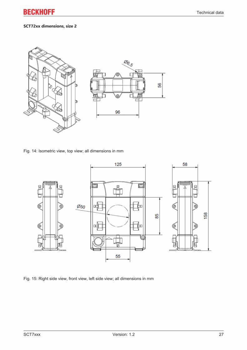
SCT72xx dimensions, size 2
Fig. 14: Isometric view, top view; all dimensions in mm
Fig. 15: Right side view, front view, left side view; all dimensions in mm
Technical data
SCT7xxx28 Version: 1.2
3.2.2 SCT7215 | Busbar split-core current transformer for primarycurrents 0…500/0…600 A, accuracy class 1, size 2
Technical data SCT7215-xxxxAccuracy class 1Primary current 0…500 A AC / 0…600 A ACSecondary current 5 A AC
VersionsSCT7215-0500 ratio 500/5,
rated power 5.0 VASCT7215-0600 ratio 600/5,
rated power 5.0 VA
Technical data
SCT7xxx 29Version: 1.2
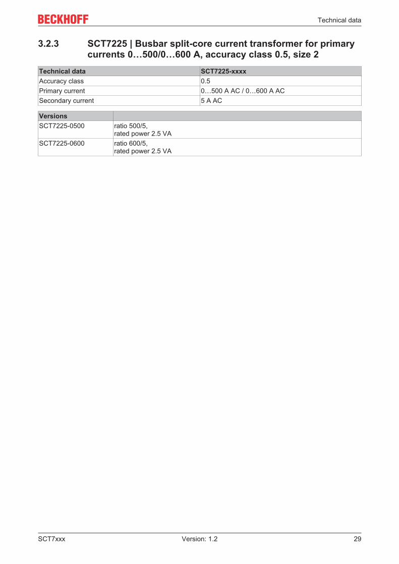
3.2.3 SCT7225 | Busbar split-core current transformer for primarycurrents 0…500/0…600 A, accuracy class 0.5, size 2
Technical data SCT7225-xxxxAccuracy class 0.5Primary current 0…500 A AC / 0…600 A ACSecondary current 5 A AC
VersionsSCT7225-0500 ratio 500/5,
rated power 2.5 VASCT7225-0600 ratio 600/5,
rated power 2.5 VA

Technical data
SCT7xxx30 Version: 1.2
3.3 SCT73xx | Busbar split-core current transformers,size 3
3.3.1 SCT73xx | GeneralPrimary side SCT73xx-xxxxThermal rated continuous current Icth 1,0 * IN
Rated short-time thermal current Ith 60 * IN/1 s (max. 100 kA)Rated impulse current Idyn 2,5 * Ith
Rated frequency fR 50..60 Hz
Secondary side SCT73xx-xxxxSecondary rated current Isr 5 AOvercurrent limiting factor FS5
Operating conditions SCT73xx-xxxxPermissible ambient temperature range duringoperation
-5…+40 °C
Permissible ambient temperature range duringstorage
-25 … +70 °C
Permissible relative humidi 5 … 85 %Operating height Up to 1000 mProtection class IP20
Insulation characteristics SCT73xx-xxxxRated insulation level Um 0,72/3/- kVInsulation class E
Gerneral data SCT73xx-xxxxMax. Diameter conductor bushing primary conductor 80 mm x 120 mmConnection technology secondary Screw terminals M5x8Conductor cross section secondary 4 mm² with ferrule
6 mm² massiveSize 3Dimensions (W x H x D) 155 mm x 198 mm x 58 mmWeight 1300 g
Standards and regulations SCT73xx-xxxxApprovals/Markings CEStandards/Regulations EN 61869-1; EN 61869-2; IEC 61010-1
Technical data
SCT7xxx 31Version: 1.2
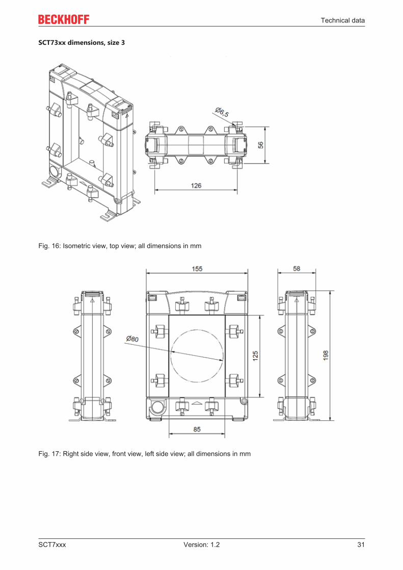
SCT73xx dimensions, size 3
Fig. 16: Isometric view, top view; all dimensions in mm
Fig. 17: Right side view, front view, left side view; all dimensions in mm
Technical data
SCT7xxx32 Version: 1.2
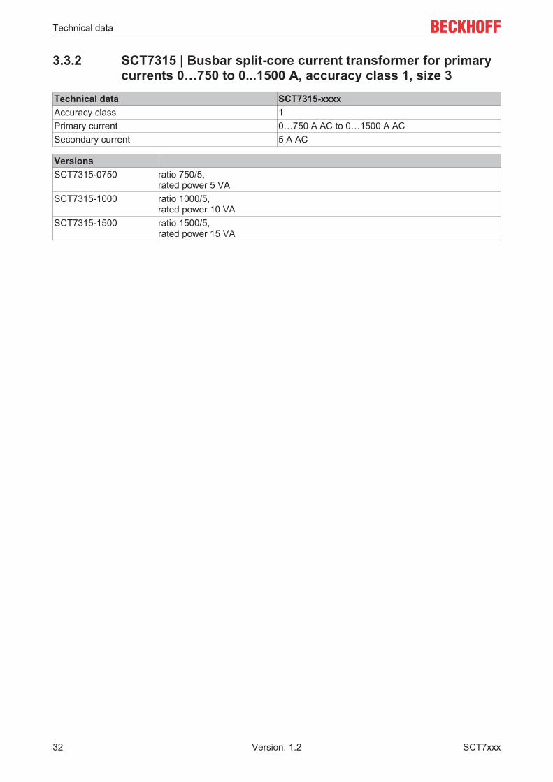
3.3.2 SCT7315 | Busbar split-core current transformer for primarycurrents 0…750 to 0...1500 A, accuracy class 1, size 3
Technical data SCT7315-xxxxAccuracy class 1Primary current 0…750 A AC to 0…1500 A ACSecondary current 5 A AC
VersionsSCT7315-0750 ratio 750/5,
rated power 5 VASCT7315-1000 ratio 1000/5,
rated power 10 VASCT7315-1500 ratio 1500/5,
rated power 15 VA
Technical data
SCT7xxx 33Version: 1.2
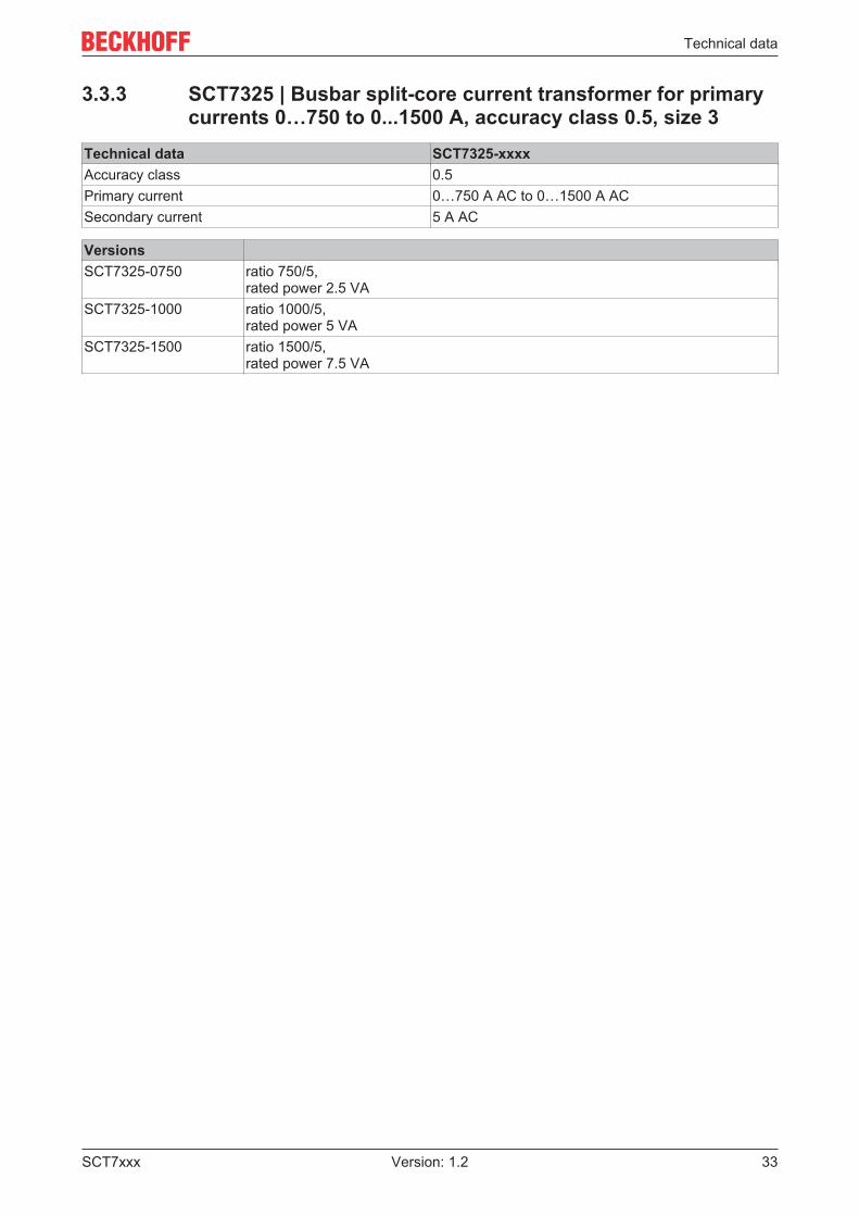
3.3.3 SCT7325 | Busbar split-core current transformer for primarycurrents 0…750 to 0...1500 A, accuracy class 0.5, size 3
Technical data SCT7325-xxxxAccuracy class 0.5Primary current 0…750 A AC to 0…1500 A ACSecondary current 5 A AC
VersionsSCT7325-0750 ratio 750/5,
rated power 2.5 VASCT7325-1000 ratio 1000/5,
rated power 5 VASCT7325-1500 ratio 1500/5,
rated power 7.5 VA

Technical data
SCT7xxx34 Version: 1.2
3.4 SCT74xx | Busbar split-core current transformers,size 4
3.4.1 SCT74xx | GeneralPrimary side SCT74xx-xxxxThermal rated continuous current Icth 1,0 * IN
Rated short-time thermal current Ith 60 * IN/1 s (max. 100 kA)Rated impulse current Idyn 2,5 * Ith
Rated frequency fR 50..60 Hz
Secondary side SCT74xx-xxxxSecondary rated current Isr 5 AOvercurrent limiting factor FS15
Operating conditions SCT74xx-xxxxPermissible ambient temperature range duringoperation
-5…+40 °C
Permissible ambient temperature range duringstorage
-25 … +70 °C
Permissible relative humidi 5 … 85 %Operating height Up to 1000 mProtection class IP20
Insulation characteristics SCT74xx-xxxxRated insulation level Um 0,72/3/- kVInsulation class E
Gerneral data SCT74xx-xxxxMax. Diameter conductor bushing primary conductor 80 mm x 160 mmConnection technology secondary Screw terminals M5x8Conductor cross section secondary 4 mm² with ferrule
6 mm² massiveSize 4Dimensions (W x H x D) 195 mm x 243 mm x 64 mmWeight 3335 g
Standards and regulations SCT74xx-xxxxApprovals/Markings CEStandards/Regulations EN 61869-1; EN 61869-2; IEC 61010-1
Technical data
SCT7xxx 35Version: 1.2
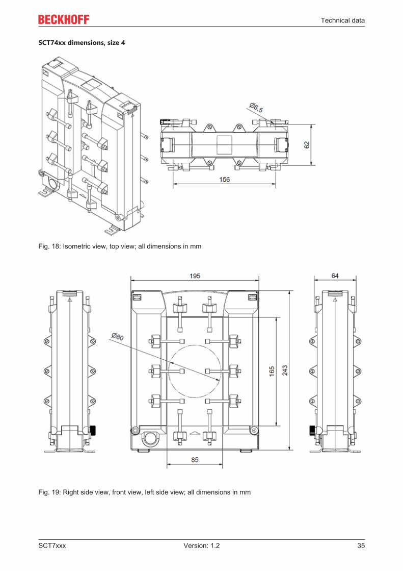
SCT74xx dimensions, size 4
Fig. 18: Isometric view, top view; all dimensions in mm
Fig. 19: Right side view, front view, left side view; all dimensions in mm
Technical data
SCT7xxx36 Version: 1.2
3.4.2 SCT7415 | Busbar split-core current transformer for primarycurrents 0…1500 to 0…5000 A, accuracy class 1, size 4
Technical data SCT7415-xxxxAccuracy class 1Primary current 0…1500 A AC to 0…5000 A ACSecondary current 5 A AC
VersionsSCT7415-1500 ratio 1500/5,
rated power 15 VASCT7415-2000 ratio 2000/5,
rated power 15 VASCT7415-2500 ratio 2500/5,
rated power 15 VASCT7415-3000 ratio 3000/5,
rated power 30 VASCT7415-4000 ratio 4000/5,
rated power 30 VASCT7415-5000 ratio 5000/5,
rated power 30 VA
Technical data
SCT7xxx 37Version: 1.2
3.4.3 SCT7425 | Busbar split-core current transformer for primarycurrents 0...1500 to 0...5000 A, accuracy class 0.5, size 4
Technical data SCT7425-xxxxAccuracy class 0.5Primary current 0…1500 A AC to 0…5000 A ACSecondary current 5 A AC
VersionsSCT7425-1500 ratio 1500/5,
rated power 15 VASCT7425-2000 ratio 2000/5,
rated power 15 VASCT7425-2500 ratio 2500/5,
rated power 15 VASCT7425-3000 ratio 3000/5,
rated power 15 VASCT7425-4000 ratio 4000/5,
rated power 30 VASCT7425-5000 ratio 5000/5,
rated power 30 VA
Commissioning
SCT7xxx38 Version: 1.2
4 Commissioning
4.1 Installation DANGER
Open transformer circuits lead to electric shock and arc flashover!Disregarding this will result in death, physical injury or considerable damage to property!• Never open the secondary circuit of the current transformer under load.• Short-circuit the secondary current terminals of the current transformer before removing the device.
WARNINGHazardous voltage can lead to electric shock and burns!• Make sure that the details on the name plate and in the "Technical data" correspond to the operating pa-
rameters of the system.• Switch the system off before commencing with the installation!
WARNINGInduction of high voltages into the secondary circuit!• If the secondary circuit of the current transformer is not under load (open), high voltages are induced on
its secondary terminals. The voltage values occurring there represent a danger to persons and the func-tional safety of the current transformer.
• "Open operation", i.e. operation of the current transformer without secondary wiring, must be avoided atall costs.
• Make sure that the working environment is safe during assembly, maintenance and installation work.Interrupt the power supply of the primary conductor and secure against being switched on againinadvertently.
• Open the current transformer and fasten it to the primary conductor with the help of the fixing claspsincluded in the scope of delivery. P1 points towards the current source, P2 towards the consumer.The arrow on the name plate shows the direction of the energy flow.Caution: Do not close the current transformer yet – high voltages could occur on the secondaryconnections!Caution: Makes sure that the cut surfaces of the separated core are clean. Avoid hand contact(sweat)!
• Connect the secondary conductors of the current transformer to the measuring device (ammeter,meter, etc.). Observe the operating instructions for the measuring device when doing this.
• Check whether the current transformer is mounted correctly and the secondary conductors areconnected correctly.
• Close the current transformer – press together until the closure engages.• If necessary, switch on the power supply to the primary conductor again.
Commissioning
SCT7xxx 39Version: 1.2
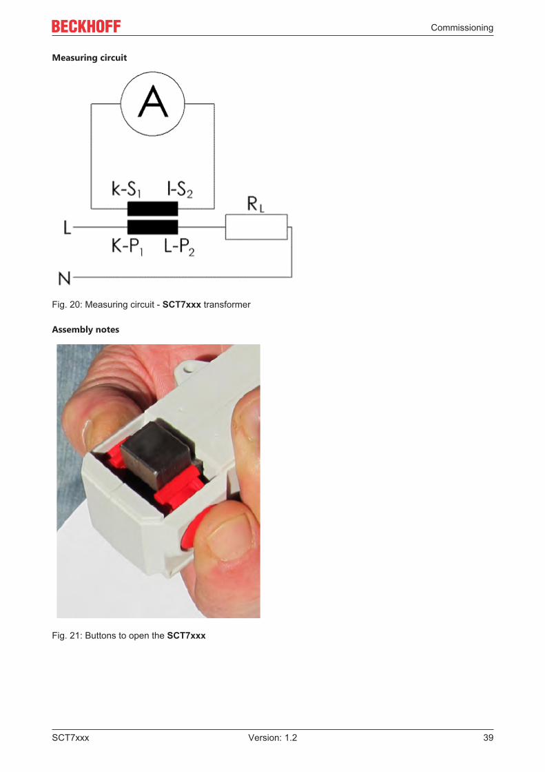
Measuring circuit
Fig. 20: Measuring circuit - SCT7xxx transformer
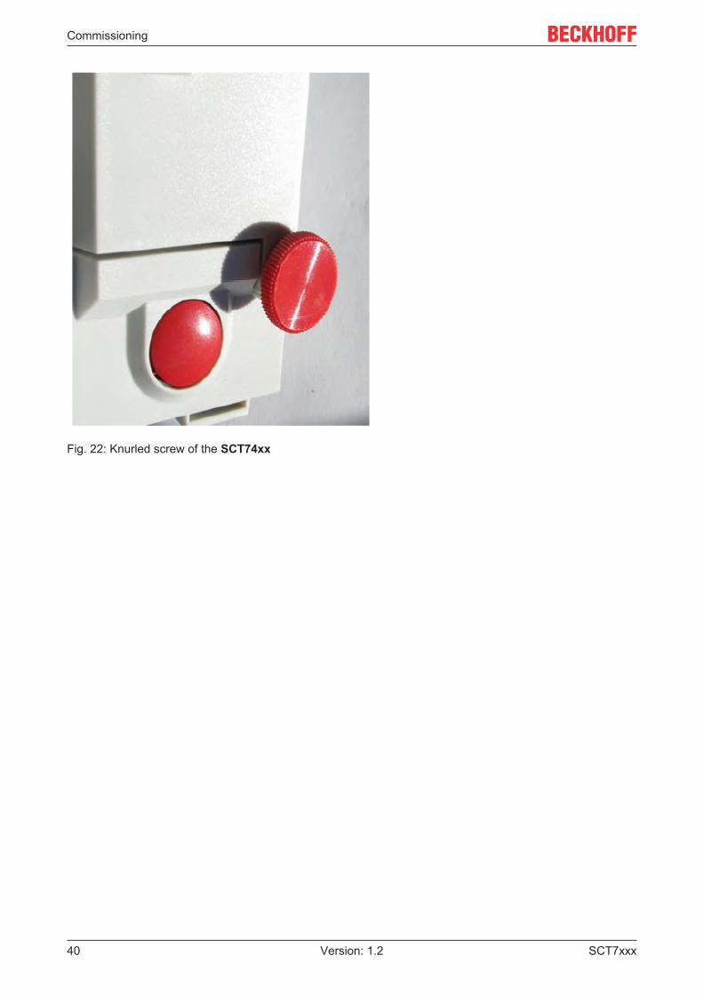
Assembly notes
Fig. 21: Buttons to open the SCT7xxx
Commissioning
SCT7xxx40 Version: 1.2
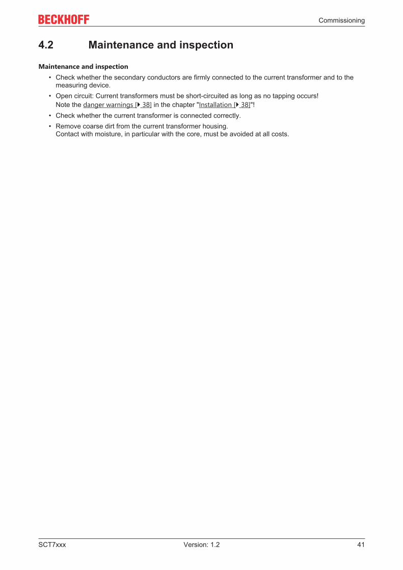
Fig. 22: Knurled screw of the SCT74xx
Commissioning
SCT7xxx 41Version: 1.2
4.2 Maintenance and inspection
Maintenance and inspection• Check whether the secondary conductors are firmly connected to the current transformer and to the
measuring device.• Open circuit: Current transformers must be short-circuited as long as no tapping occurs!
Note the danger warnings [} 38] in the chapter "Installation [} 38]"!• Check whether the current transformer is connected correctly.• Remove coarse dirt from the current transformer housing.
Contact with moisture, in particular with the core, must be avoided at all costs.
Commissioning
SCT7xxx42 Version: 1.2
4.3 Troubleshooting
Troubleshooting
In the case of errors, e.g. unexpected or incorrect values, inverse power:
• Check the settings of the measuring device on the basis of its operating instructions.• Check whether the current transformer is mounted on the intended conductor in the direction of the
energy flow.• Check the connection of the current transformers and the corresponding voltage tap-off if the active
and/or reactive power does not correspond to the expected values; if necessary, one phase has beenreversed.
• Check whether the current transformer is connected correctly.• Check the power requirement of the conductors and measuring devices connected to the current
transformer. It must not exceed the rated power of the current transformer (see name plate).• If the above points do not solve the problem:
Check whether there is dust or other dirt between the two parts of the core. If so, clean the surfacescarefully with a lint-free cloth.
• Avoid hand contact (sweat)!
Application example
SCT7xxx 43Version: 1.2
5 Application example
5.1 Power measurement at a machine WARNING
WARNING: Risk of electric shock!Bring the Bus Terminal system into a safe, voltage-free state before starting mounting, disassembly orwiring of the Bus Terminals!
NOTEAttention! Risk of device damage!Avoid confusing the current and voltage circuit during connection, since the direct connection of mains volt-age to the terminal points for the current transformers (typical input resistance 100 mΩ) would destroy thepower measurement terminal!
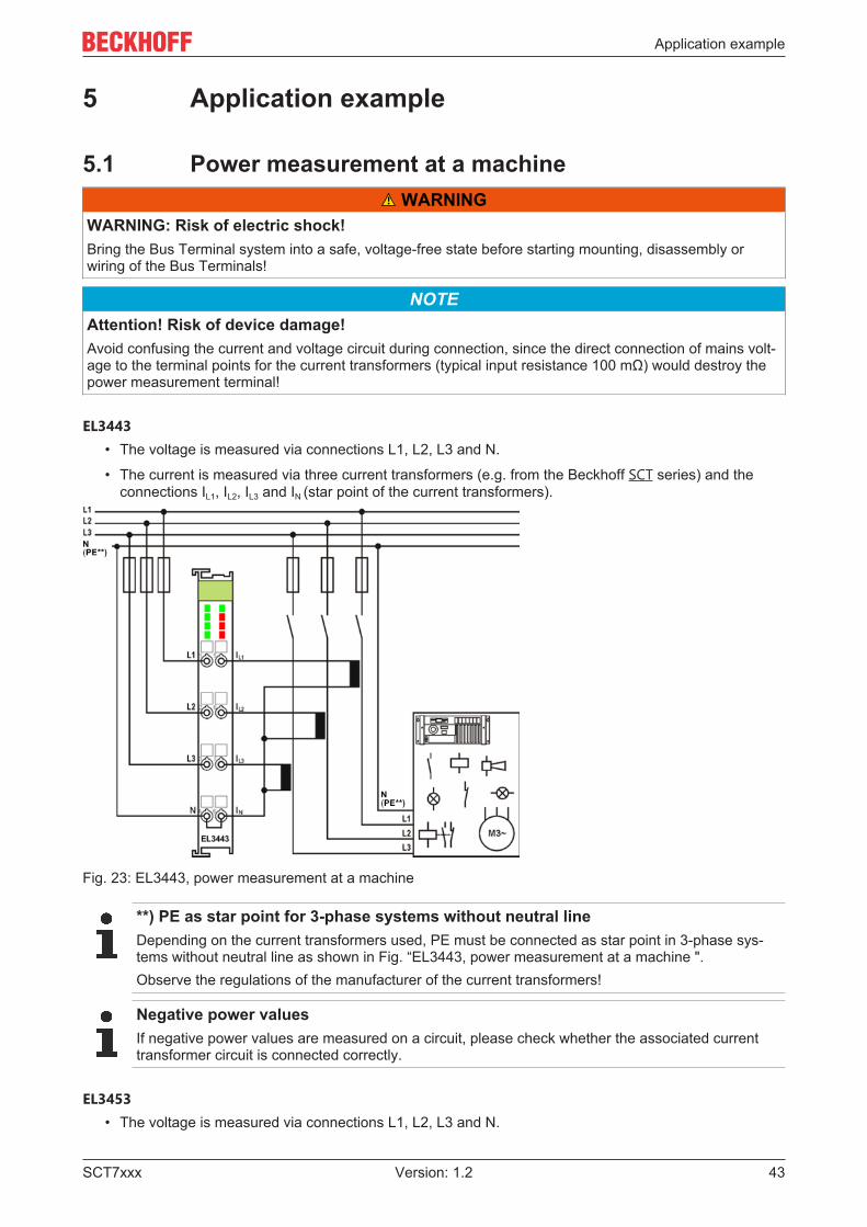
EL3443• The voltage is measured via connections L1, L2, L3 and N.
• The current is measured via three current transformers (e.g. from the Beckhoff SCT series) and theconnections IL1, IL2, IL3 and IN (star point of the current transformers).
Fig. 23: EL3443, power measurement at a machine
**) PE as star point for 3-phase systems without neutral lineDepending on the current transformers used, PE must be connected as star point in 3-phase sys-tems without neutral line as shown in Fig. “EL3443, power measurement at a machine ".Observe the regulations of the manufacturer of the current transformers!
Negative power valuesIf negative power values are measured on a circuit, please check whether the associated currenttransformer circuit is connected correctly.
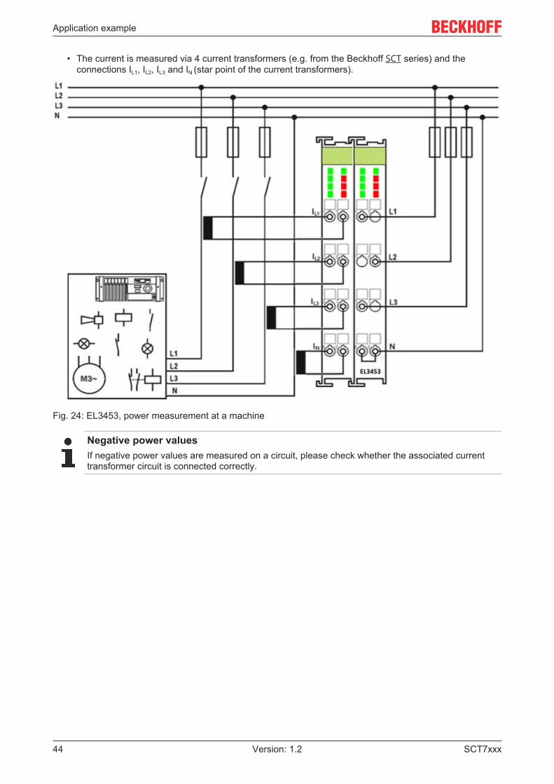
EL3453• The voltage is measured via connections L1, L2, L3 and N.
Application example
SCT7xxx44 Version: 1.2
• The current is measured via 4 current transformers (e.g. from the Beckhoff SCT series) and theconnections IL1, IL2, IL3 and IN (star point of the current transformers).
Fig. 24: EL3453, power measurement at a machine
Negative power valuesIf negative power values are measured on a circuit, please check whether the associated currenttransformer circuit is connected correctly.

Appendix
SCT7xxx 45Version: 1.2
6 Appendix
6.1 Documentation issue statusVersion Comment1.2 - Addenda chapter ”Notes on class accuracy SCT transformers”1.1 - Addenda & corrections1.0 - 1st public issue
- Addenda & corrections

Appendix
SCT7xxx46 Version: 1.2
6.2 Support and ServiceBeckhoff and their partners around the world offer comprehensive support and service, making available fastand competent assistance with all questions related to Beckhoff products and system solutions.
Beckhoff's branch offices and representatives
Please contact your Beckhoff branch office or representative for local support and service on Beckhoffproducts!
The addresses of Beckhoff's branch offices and representatives round the world can be found on her internetpages: https://www.beckhoff.com
You will also find further documentation for Beckhoff components there.
Beckhoff Support
Support offers you comprehensive technical assistance, helping you not only with the application ofindividual Beckhoff products, but also with other, wide-ranging services:
• support• design, programming and commissioning of complex automation systems• and extensive training program for Beckhoff system components
Hotline: +49 5246 963 157Fax: +49 5246 963 9157e-mail: [email protected]
Beckhoff Service
The Beckhoff Service Center supports you in all matters of after-sales service:
• on-site service• repair service• spare parts service• hotline service
Hotline: +49 5246 963 460Fax: +49 5246 963 479e-mail: [email protected]
Beckhoff Headquarters
Beckhoff Automation GmbH & Co. KG
Huelshorstweg 2033415 VerlGermany
Phone: +49 5246 963 0Fax: +49 5246 963 198e-mail: [email protected]: https://www.beckhoff.com

Beckhoff Automation GmbH & Co. KGHülshorstweg 2033415 VerlGermanyPhone: +49 5246 [email protected]
More Information: www.beckhoff.com/SCT7xxx