07-Busbar Protection Busbar Protection Rf
63
08/02 05/02/03 1 1 05/02/03 1 Busbar Protection Protection & Contrôle / Application Rev. A JM, September 2004
-
Upload
rajesh-pillai -
Category
Documents
-
view
644 -
download
67
Transcript of 07-Busbar Protection Busbar Protection Rf
08/0205/02/031 105/02/031
Busbar Protection
Protection & Contrôle / Application
Rev. A JM, September 2004
08/0205/02/032 2
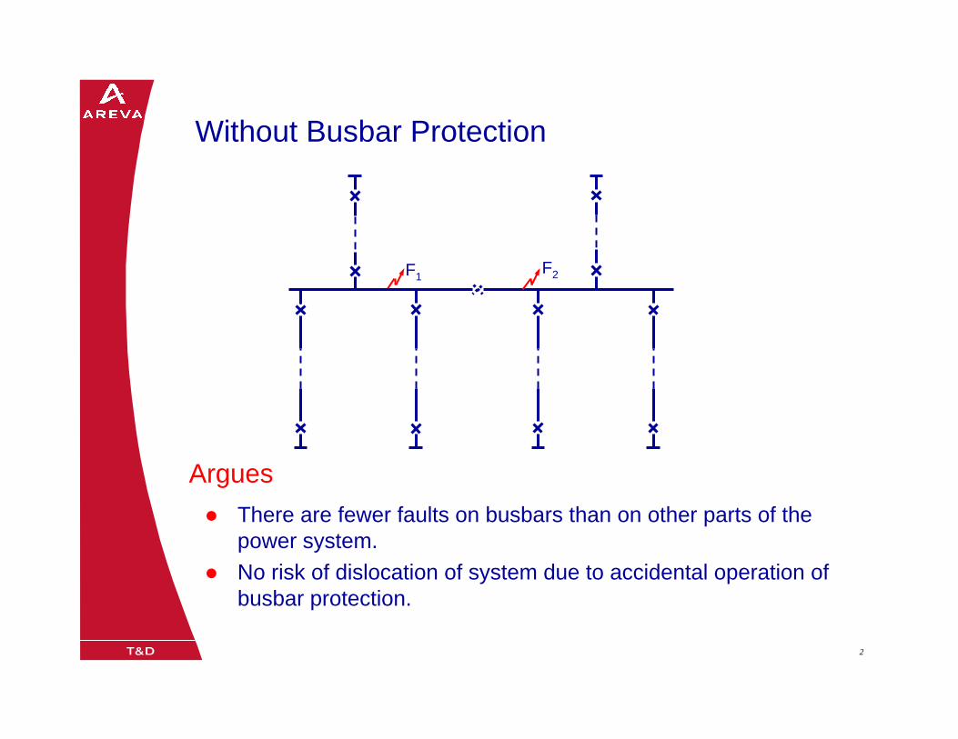
Without Busbar Protection
F2F1
There are fewer faults on busbars than on other parts of the power system. No risk of dislocation of system due to accidental operation of busbar protection.
Argues
08/0205/02/033 3
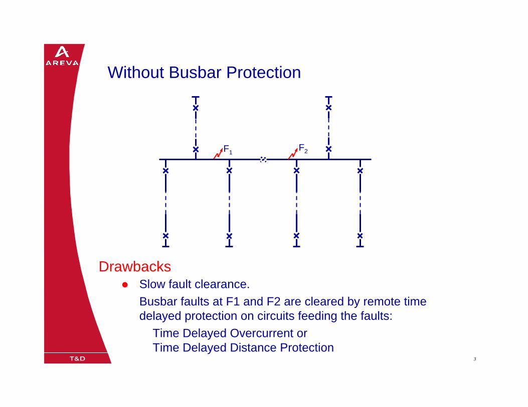
Without Busbar Protection
F2F1
Slow fault clearance.Busbar faults at F1 and F2 are cleared by remote time delayed protection on circuits feeding the faults:
Time Delayed Overcurrent orTime Delayed Distance Protection
Drawbacks
08/0205/02/034 4
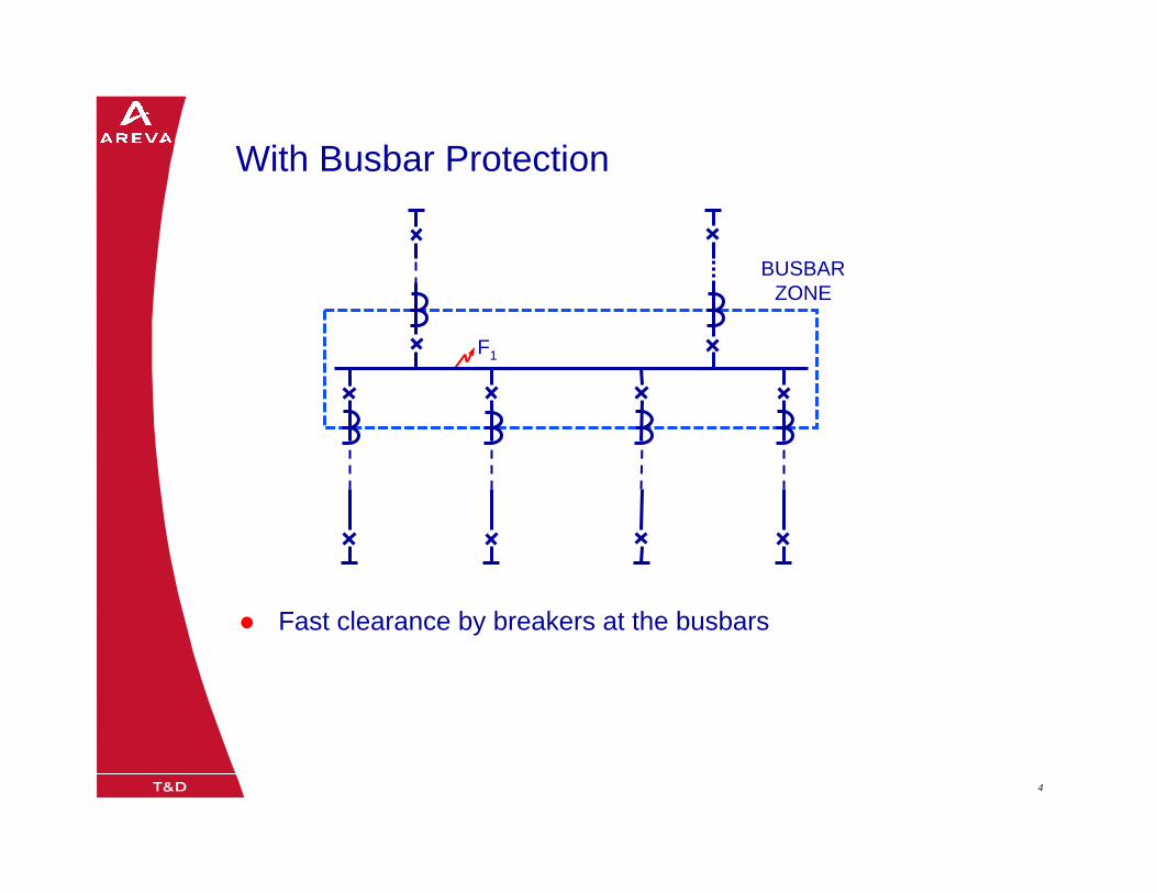
With Busbar Protection
BUSBARZONE
F1
Fast clearance by breakers at the busbars
08/0205/02/035 5
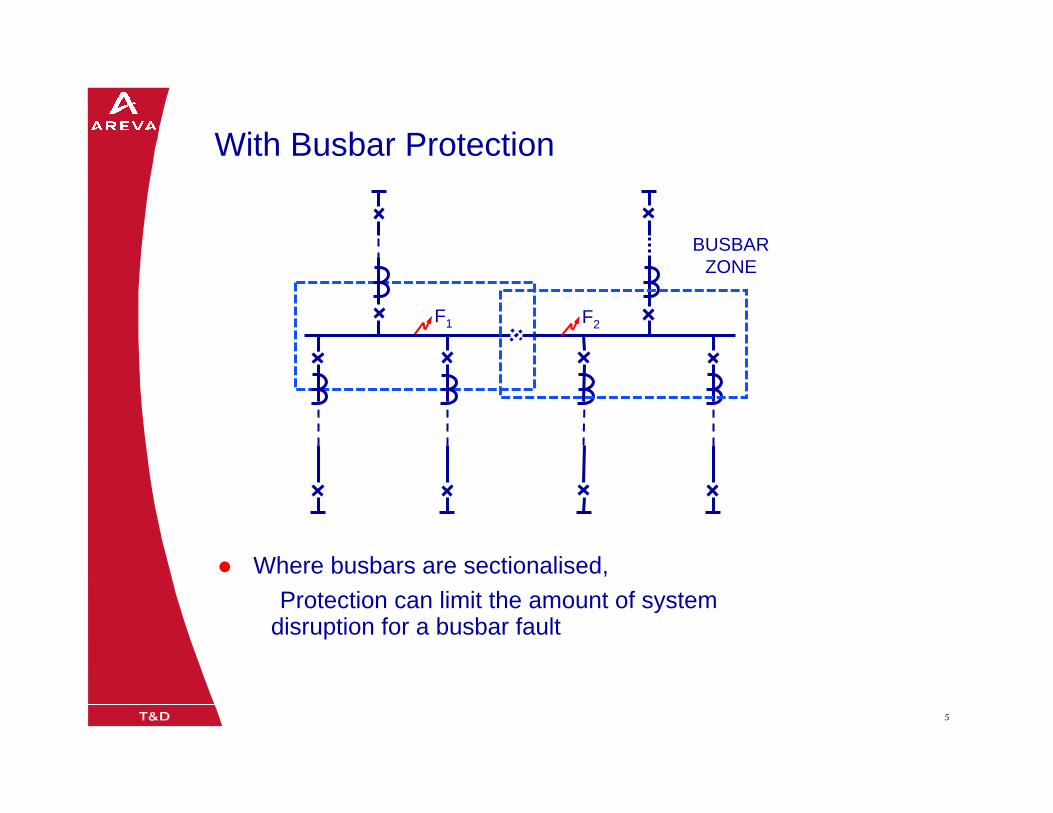
With Busbar Protection
BUSBARZONE
F2F1
Where busbars are sectionalised,Protection can limit the amount of system
disruption for a busbar fault

08/0205/02/036 6
21 21
87BB
87BB
1/2
With Busbar Protection
SS 1
SS 2
SS 3
08/0205/02/037 7
21 21
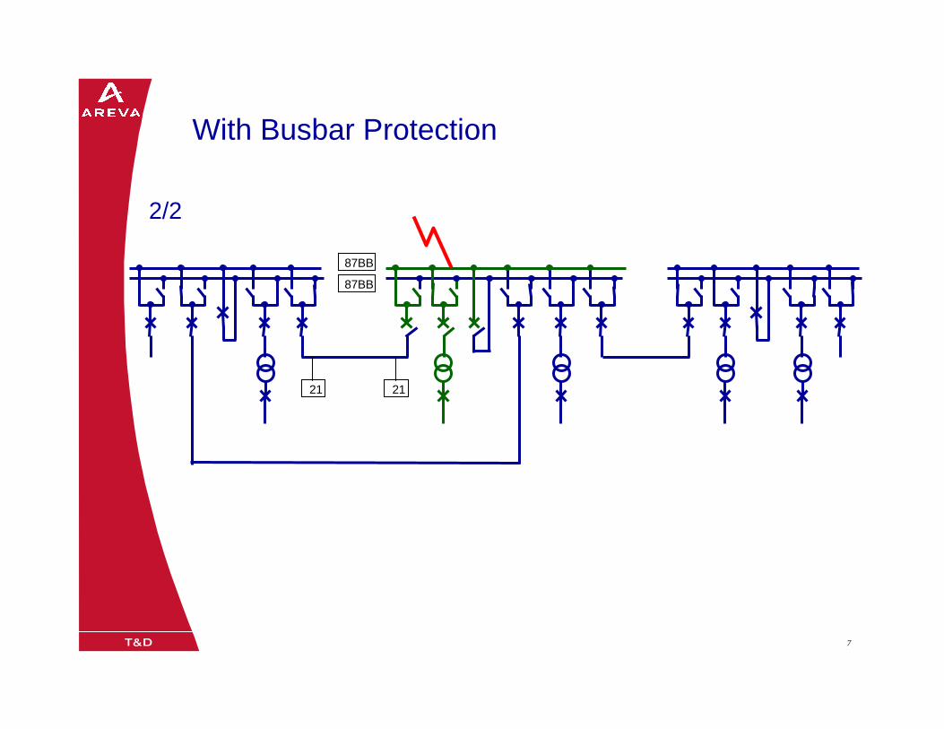
87BB
87BB
2/2
With Busbar Protection
08/0205/02/038 8
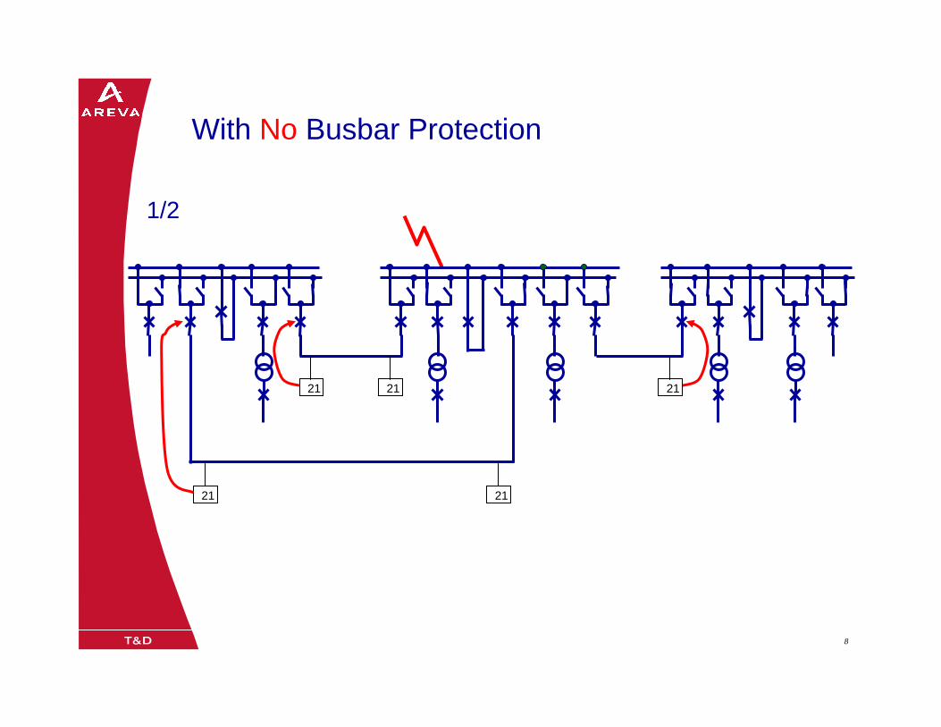
21 21 21
21 21
1/2
With No Busbar Protection
08/0205/02/039 9
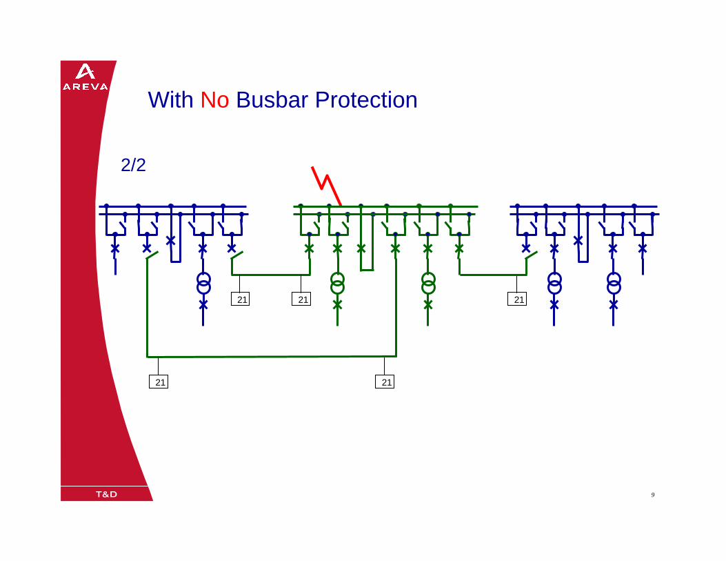
21 21
2/2
21
21 21
With No Busbar Protection
08/0205/02/0310 10
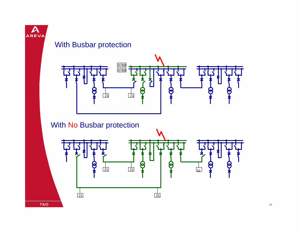
21 21 21
21 21
21 21
87BB87BB
With Busbar protection
With No Busbar protection
08/0205/02/0311 11
Busbar Faults Are Usually Permanent
Causes of Busbar Faults :
Falling debris
Insulation failuresCircuit breaker failuresCurrent transformer failuresIsolators switchs operated on load or outside their ratingsSafety earths left connected
Therefore :
Circuit breakers should be tripped and locked out by busbar protection
08/0205/02/0312 12
Busbar Protection must be :
RELIABLE– Failure to trip could cause widespread damage to the substation
STABLE– False tripping can cause widespread interruption of supplies to
customers / possible power system instability
DISCRIMINATING– Should trip the minimum number of breakers to clear the fault
FAST– To limit damage and possible power system instability
08/0205/02/0313 13
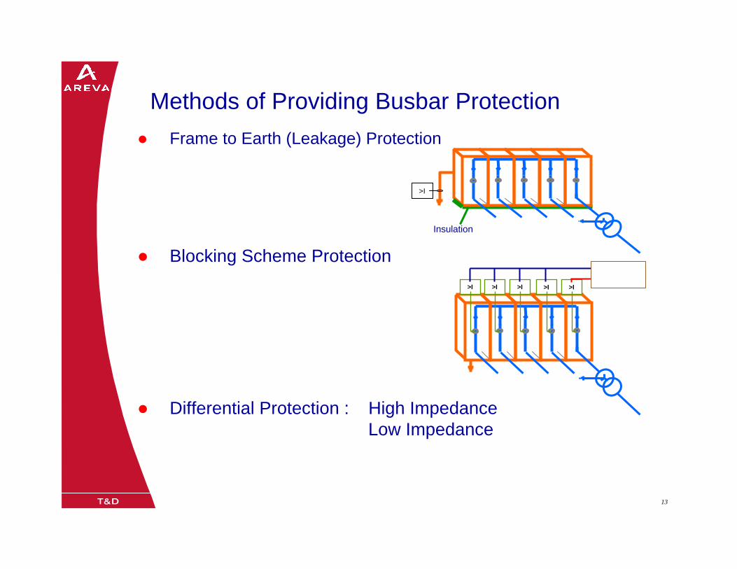
Methods of Providing Busbar ProtectionFrame to Earth (Leakage) Protection
Blocking Scheme Protection
Differential Protection : High ImpedanceLow Impedance
Insulation
>I
>I >I >I >I>I
08/0205/02/0314 1405/02/0314
Frame Leakage Protection
Protection & Contrôle / Application
Rev. A JM, September 2004
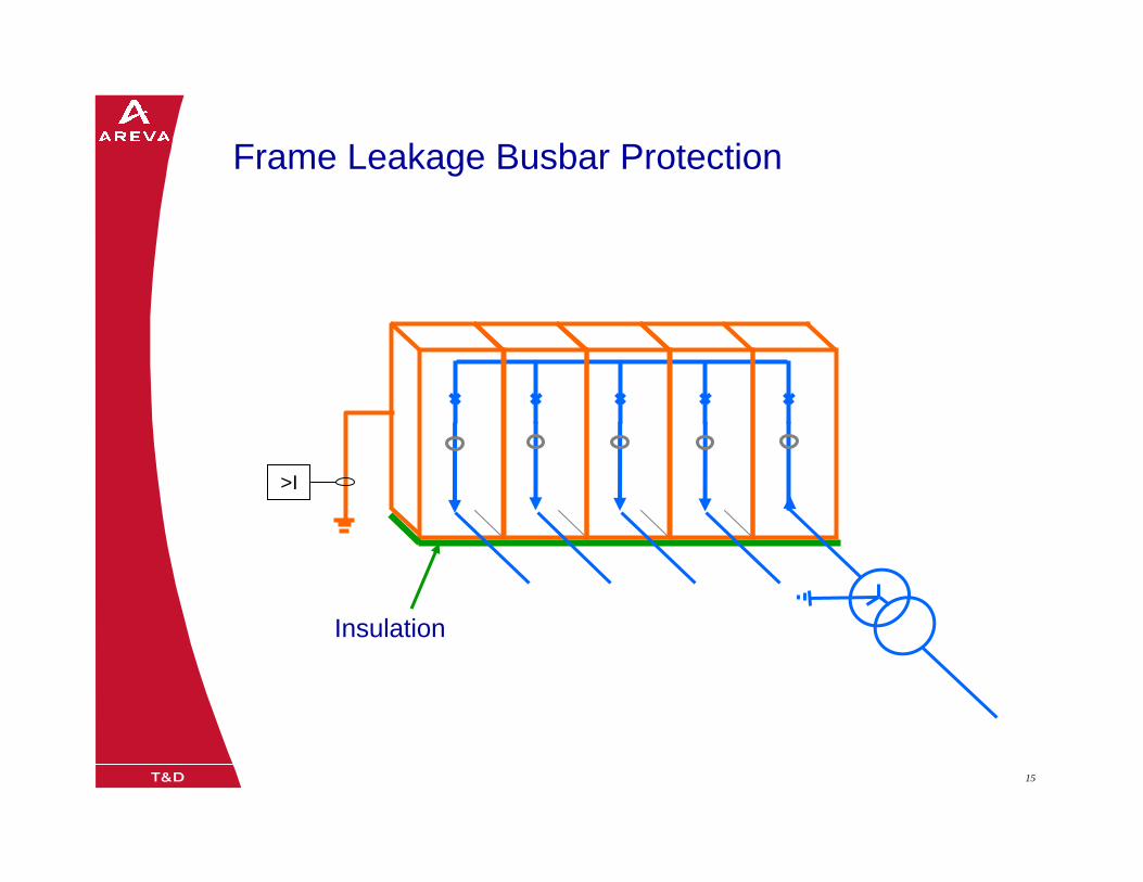
08/0205/02/0315 15
Insulation
>I
Frame Leakage Busbar Protection
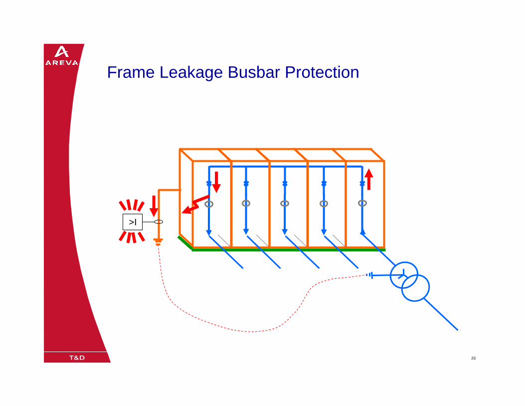
08/0205/02/0316 16
>I
Frame Leakage Busbar Protection
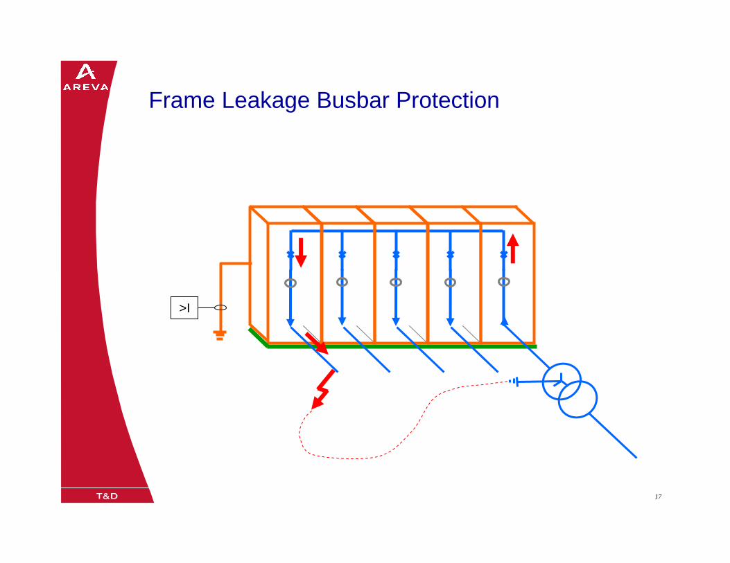
08/0205/02/0317 17
>I
Frame Leakage Busbar Protection
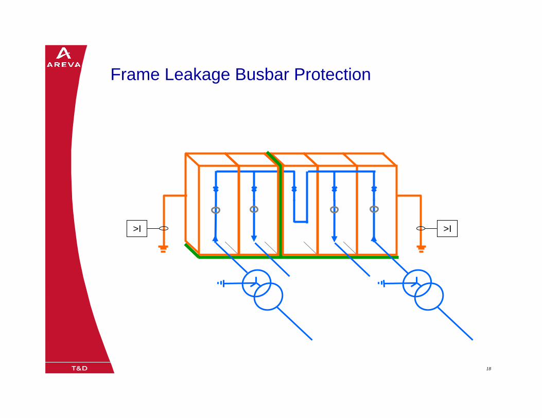
08/0205/02/0318 18
>I
Frame Leakage Busbar Protection
>I
08/0205/02/0319 19
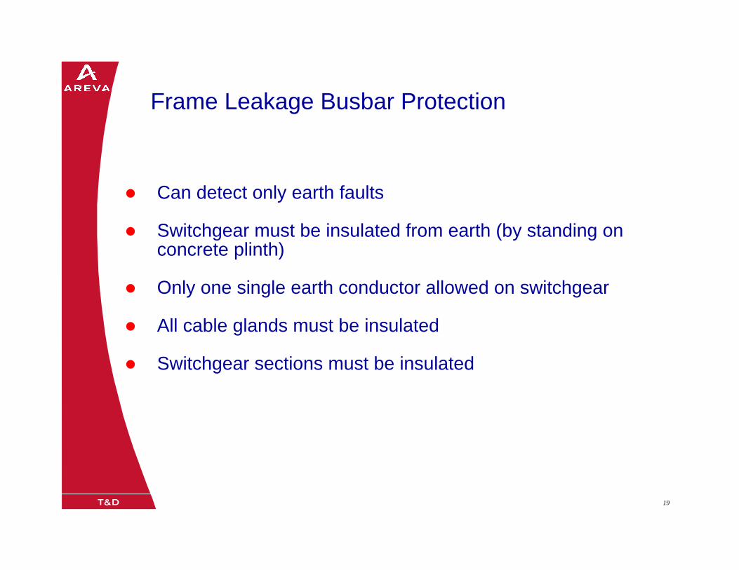
Can detect only earth faults
Switchgear must be insulated from earth (by standing on concrete plinth)
Only one single earth conductor allowed on switchgear
All cable glands must be insulated
Switchgear sections must be insulated
Frame Leakage Busbar Protection
08/0205/02/0320 20
>I
>I
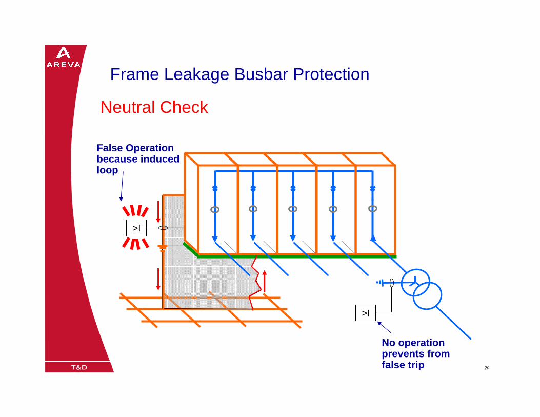
Frame Leakage Busbar Protection
Neutral Check
False Operation because induced loop
No operation prevents from false trip
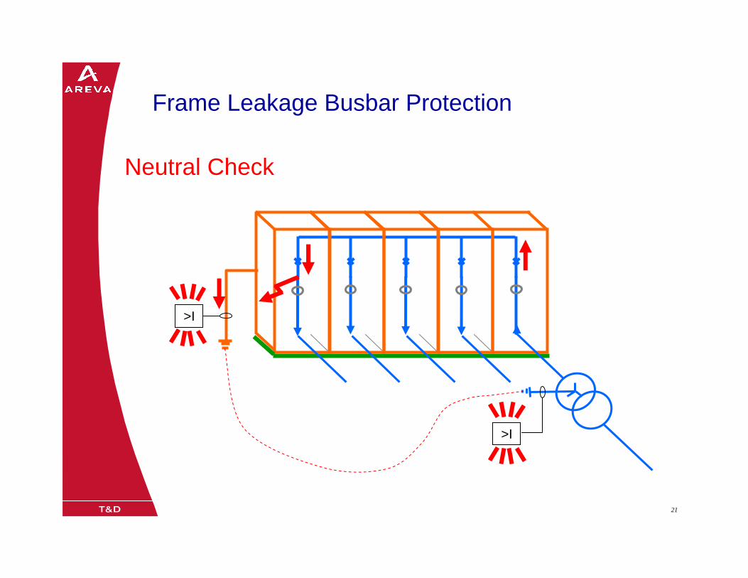
08/0205/02/0321 21
>I
>I
Frame Leakage Busbar Protection
Neutral Check
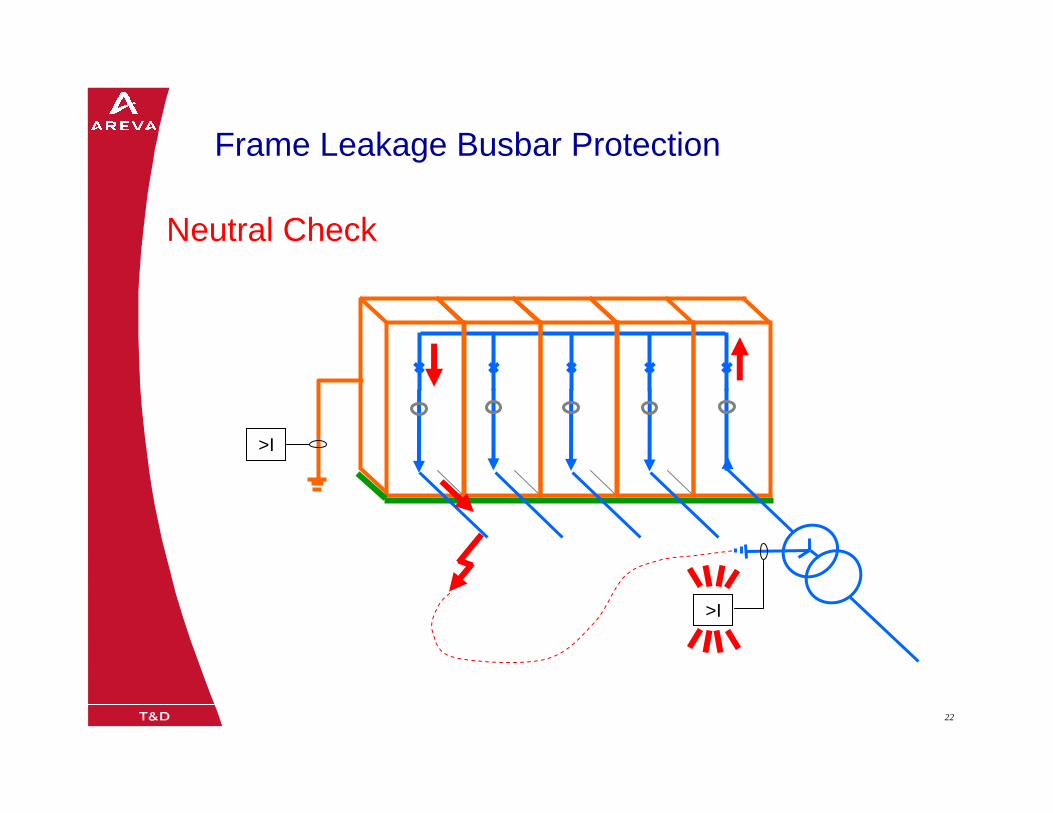
08/0205/02/0322 22
>I
>I
Neutral Check
Frame Leakage Busbar Protection

08/0205/02/0323 2305/02/0323
Blocking Scheme Protection
Protection & Contrôle / Application
Rev. A JM, September 2004
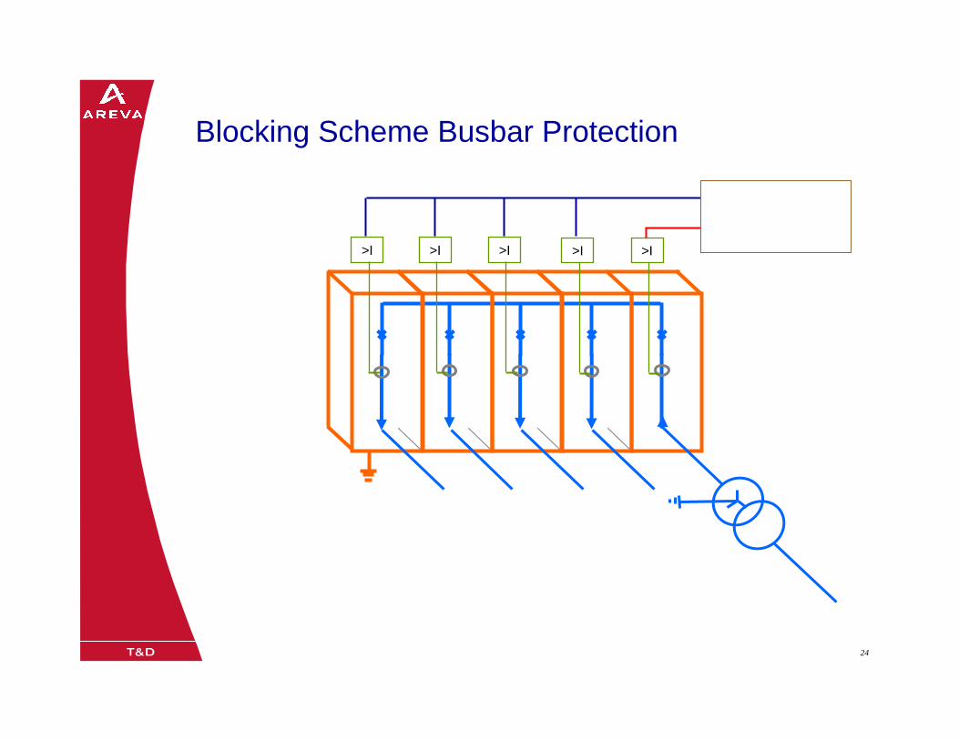
08/0205/02/0324 24
>I >I >I >I>I
Blocking Scheme Busbar Protection
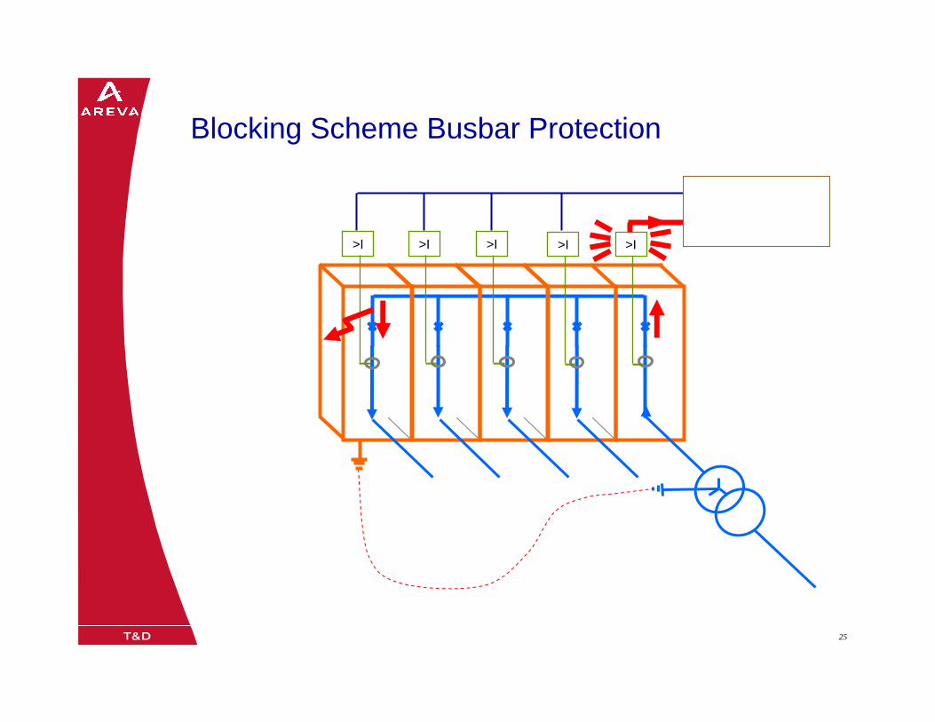
08/0205/02/0325 25
>I >I >I >I>I
Blocking Scheme Busbar Protection
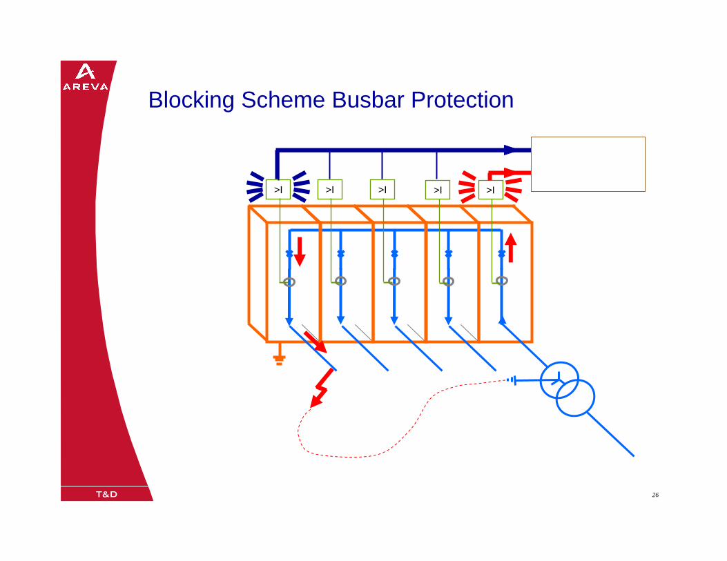
08/0205/02/0326 26
>I >I >I >I>I
Blocking Scheme Busbar Protection
08/0205/02/0327 2705/02/0327
High Impedance Protection
Protection & Contrôle / Application
Rev. A JM, September 2004

08/0205/02/0328 2808/0205/02/0328
Single Bus Substation
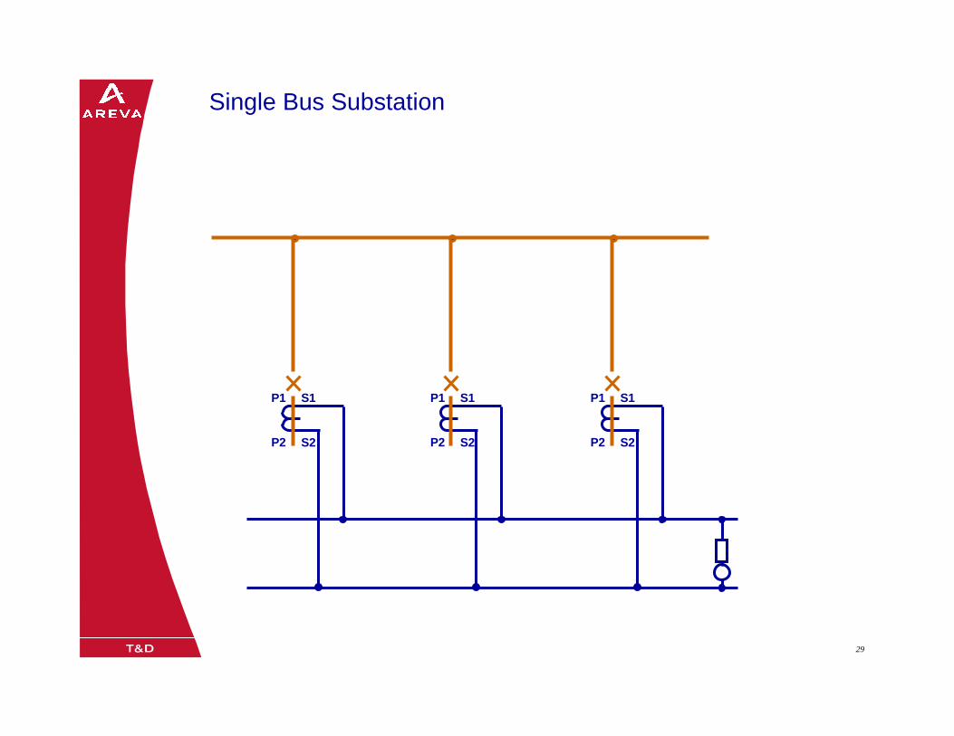
08/0205/02/0329 29
P1
P2
S1
S2
P1
P2
S1
S2
P1
P2
S1
S2
Single Bus Substation
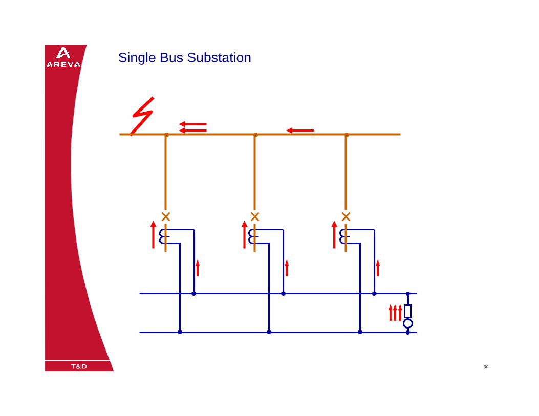
08/0205/02/0330 30
Single Bus Substation
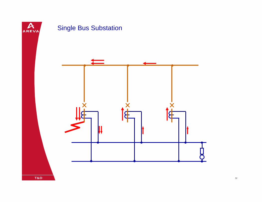
08/0205/02/0331 31
Single Bus Substation
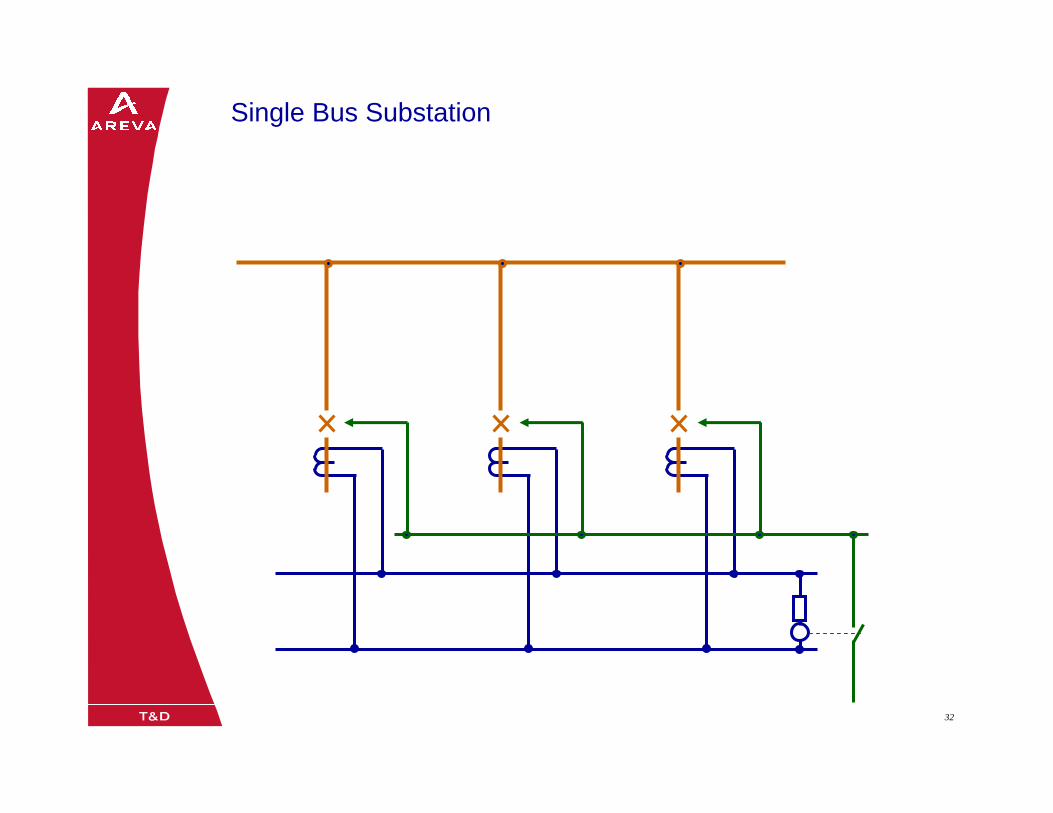
08/0205/02/0332 32
Single Bus Substation
08/0205/02/0333 3308/0205/02/0333
Double Bus Substation
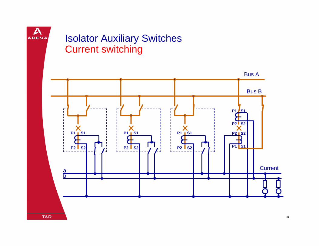
08/0205/02/0334 34
Isolator Auxiliary Switches Current switching
Bus A
Bus B
ab
Current
P1
P2
S1
S2
P1
P2
S1
S2
P1
P2
S1
S2
P1
P2
S1
S2
P1
P2
S1
S2
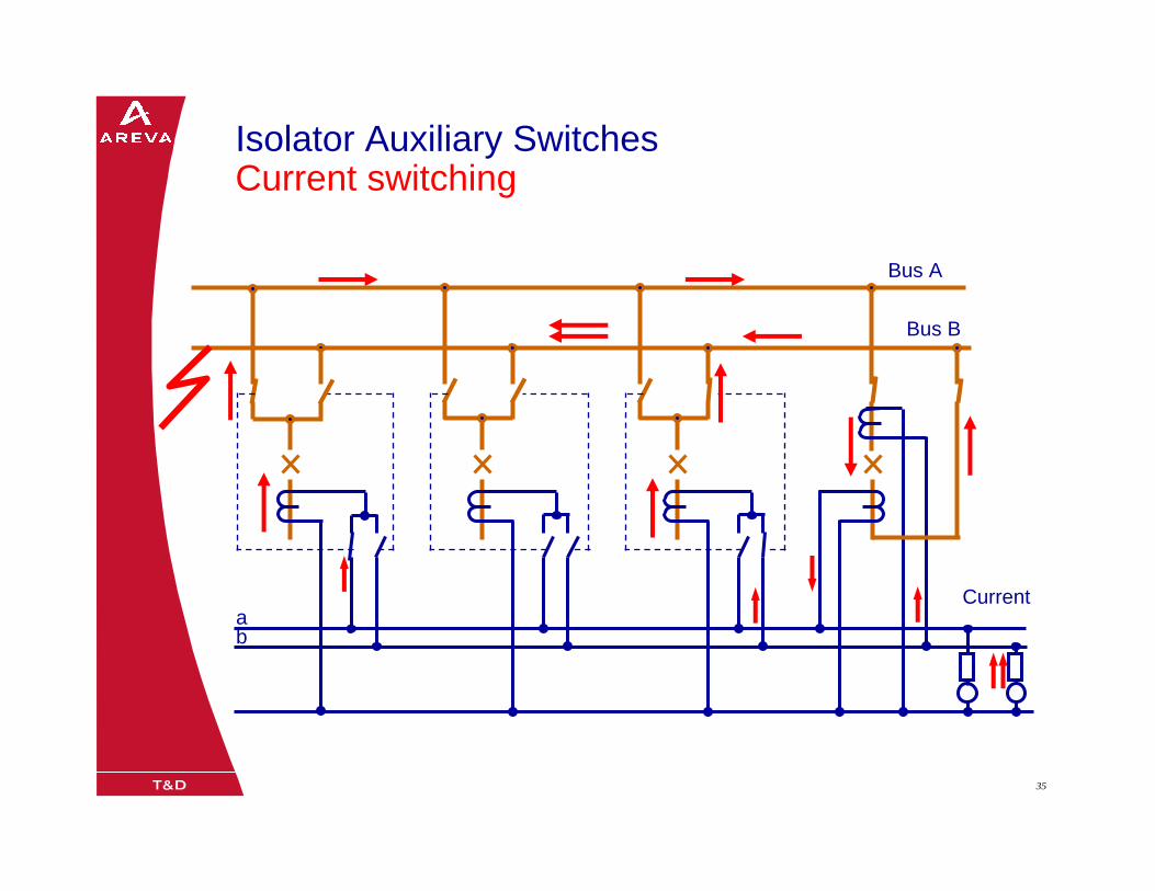
08/0205/02/0335 35
Isolator Auxiliary Switches Current switching
Bus A
Bus B
ab
Current
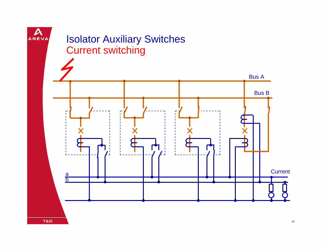
08/0205/02/0336 36
Isolator Auxiliary Switches Current switching
Bus A
Bus B
ab
Current
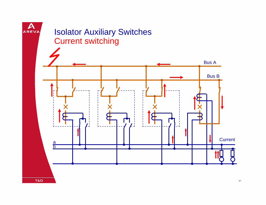
08/0205/02/0337 37
Isolator Auxiliary Switches Current switching
Bus A
Bus B
ab
Current
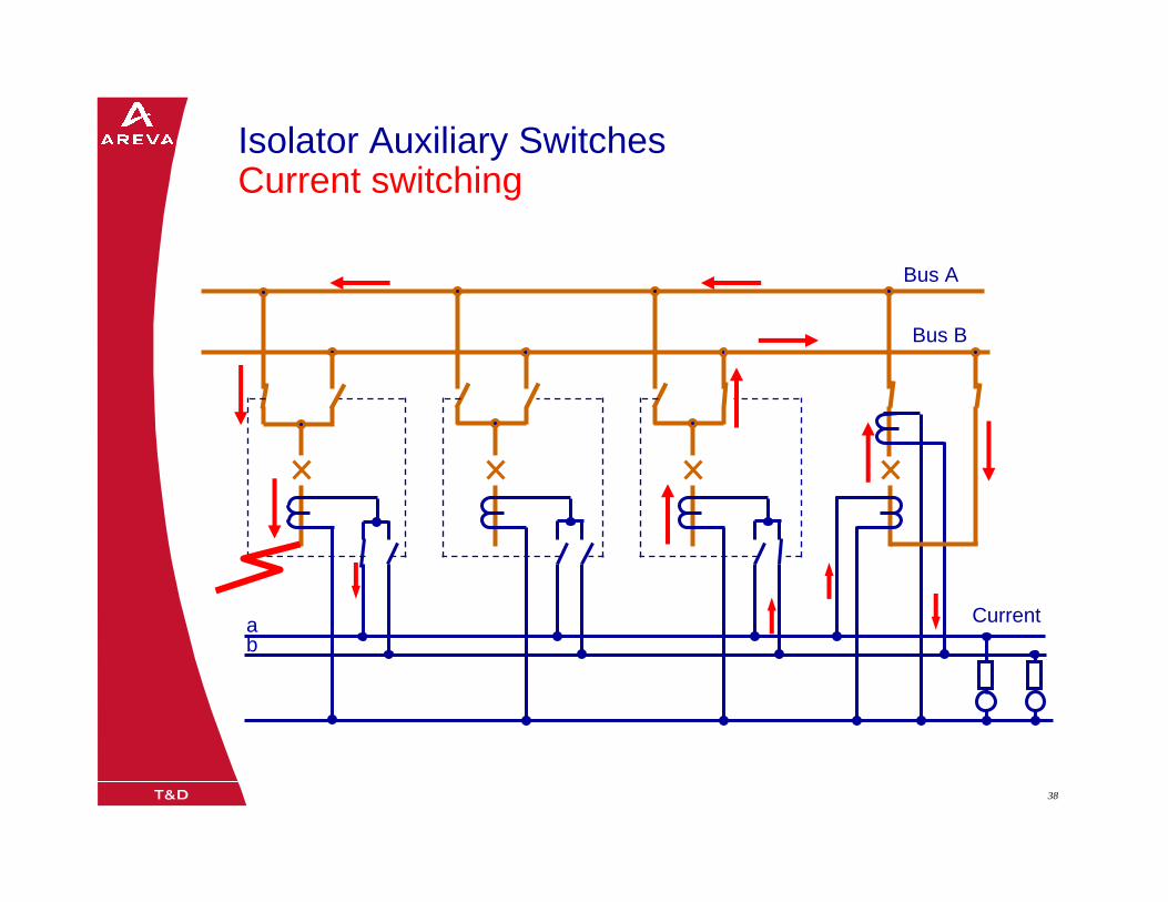
08/0205/02/0338 38
Isolator Auxiliary Switches Current switching
Bus A
Bus B
ab
Current

08/0205/02/0339 39
Isolator Auxiliary Switches Current switching
Bus A
Bus B
ab
Current
08/0205/02/0340 40
Bus A
Current
Bus B
ab
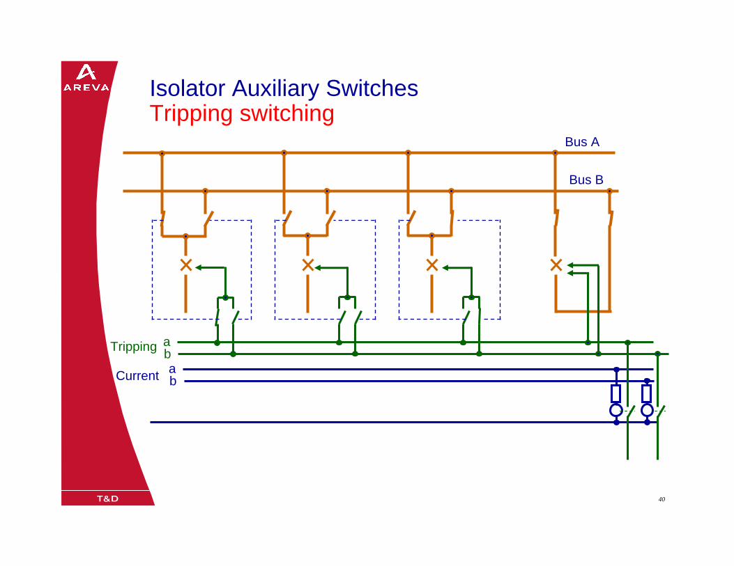
Isolator Auxiliary Switches Tripping switching
Tripping ab
08/0205/02/0341 41
Main CT must be identical
Current switching via auxilliary relay is not acceptable.
Requirement of number of position contact (Disconnector switch) is high
Interposing CT are not acceptable

08/0205/02/0342 42
Isolator Auxiliary Switches Current switching
Bus A
Bus B
abCurrent
08/0205/02/0343 43
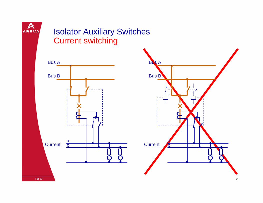
Isolator Auxiliary Switches Current switching
Bus A
Bus B
abCurrent
Bus A
Bus B
abCurrent
08/0205/02/0344 44
Bus A
Bus B
abCurrent
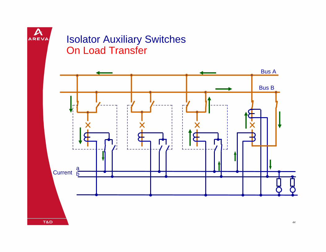
Isolator Auxiliary Switches On Load Transfer

08/0205/02/0345 45
Bus A
Bus B
abCurrent
Isolator Auxiliary Switches On Load Transfer

08/0205/02/0346 46
Bus A
Bus B
abCurrent
Isolator Auxiliary Switches On Load Transfer
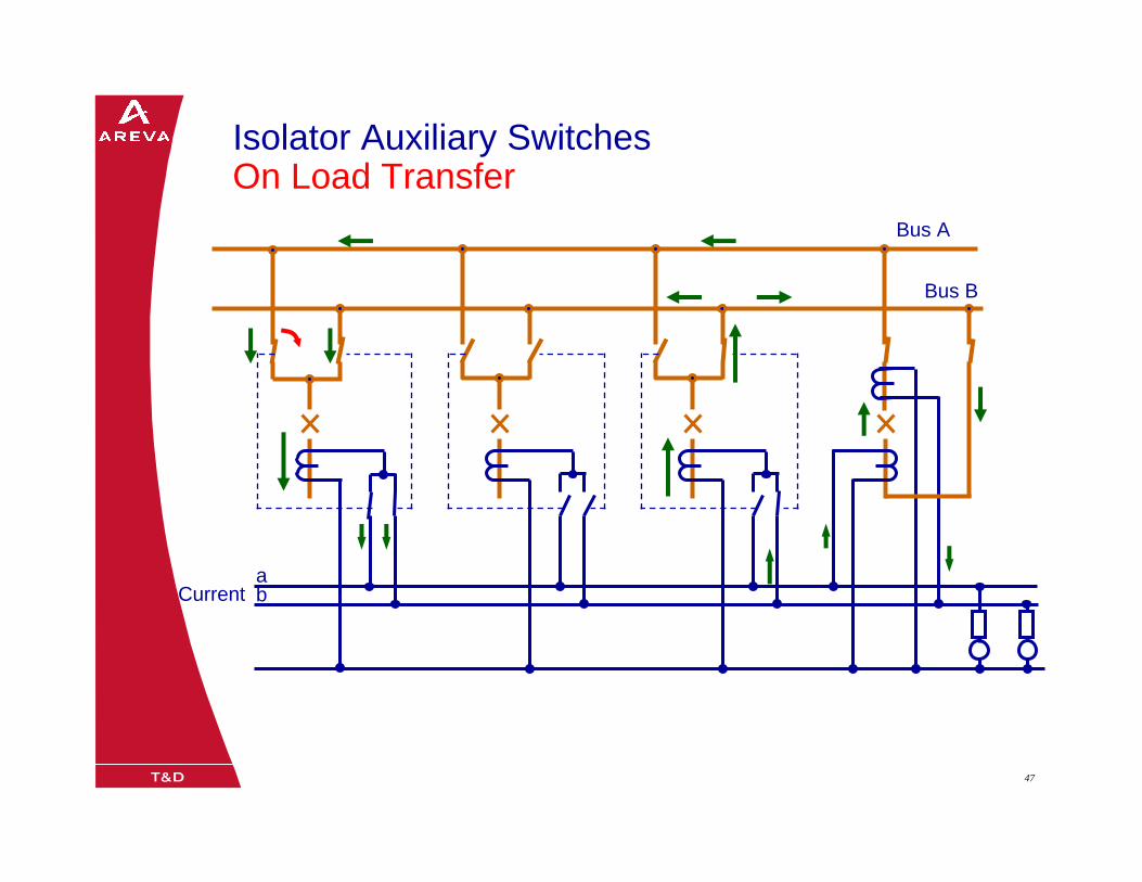
08/0205/02/0347 47
Bus A
Bus B
abCurrent
Isolator Auxiliary Switches On Load Transfer
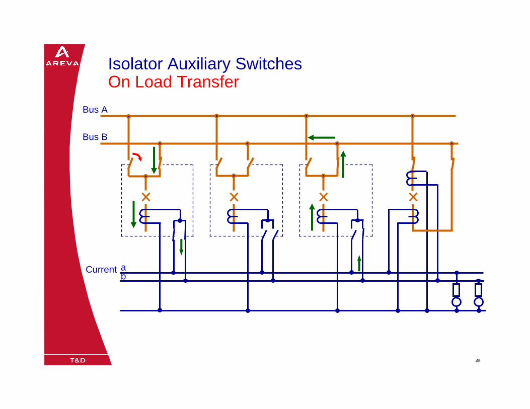
08/0205/02/0348 48
Bus A
Bus B
ab
Current
Isolator Auxiliary Switches On Load Transfer
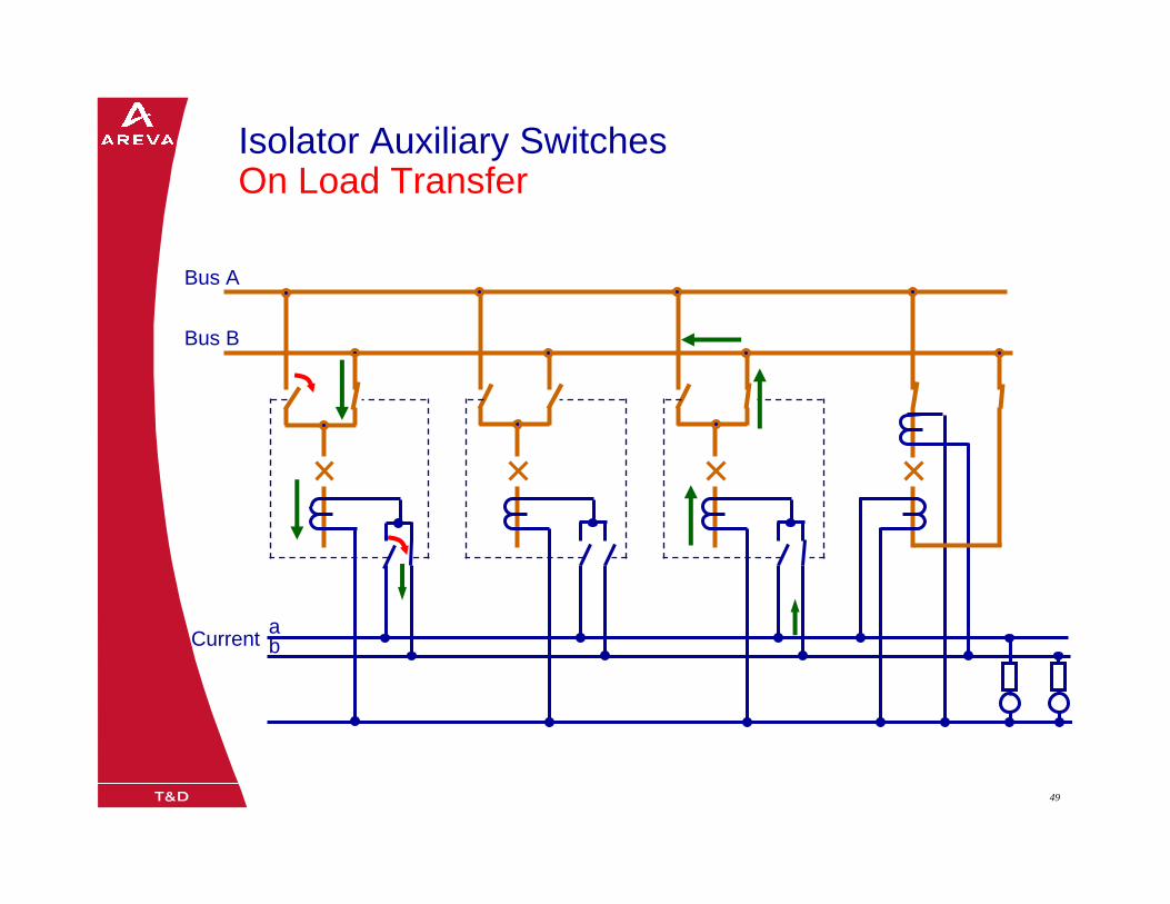
08/0205/02/0349 49
Bus A
Bus B
abCurrent
Isolator Auxiliary Switches On Load Transfer

08/0205/02/0350 50
Bus A
Bus B
abCurrent
Isolator Auxiliary Switches On Load Transfer
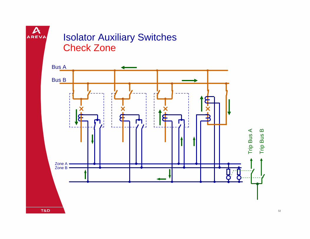
08/0205/02/0351 51
Bus A
Bus B
Trip
Bus
A
Trip
Bus
B
Zone AZone B
Isolator Auxiliary Switches Check Zone
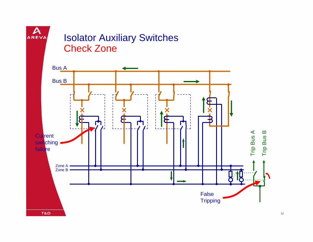
08/0205/02/0352 52
Bus A
Bus B
Trip
Bus
A
Trip
Bus
B
Zone AZone B
Isolator Auxiliary Switches Check Zone
Current switching failure
False Tripping
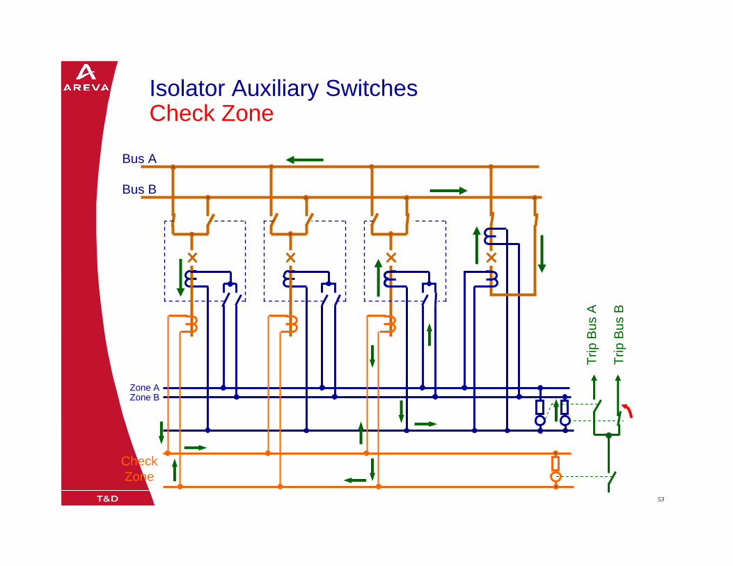
08/0205/02/0353 53
Bus A
Bus B
Trip
Bus
A
Trip
Bus
B
Check Zone
Zone AZone B
Isolator Auxiliary Switches Check Zone

08/0205/02/0354 54
Bus A
Bus B
Trip
Bus
A
Trip
Bus
B
Zone AZone B
Isolator Auxiliary Switches Check Zone
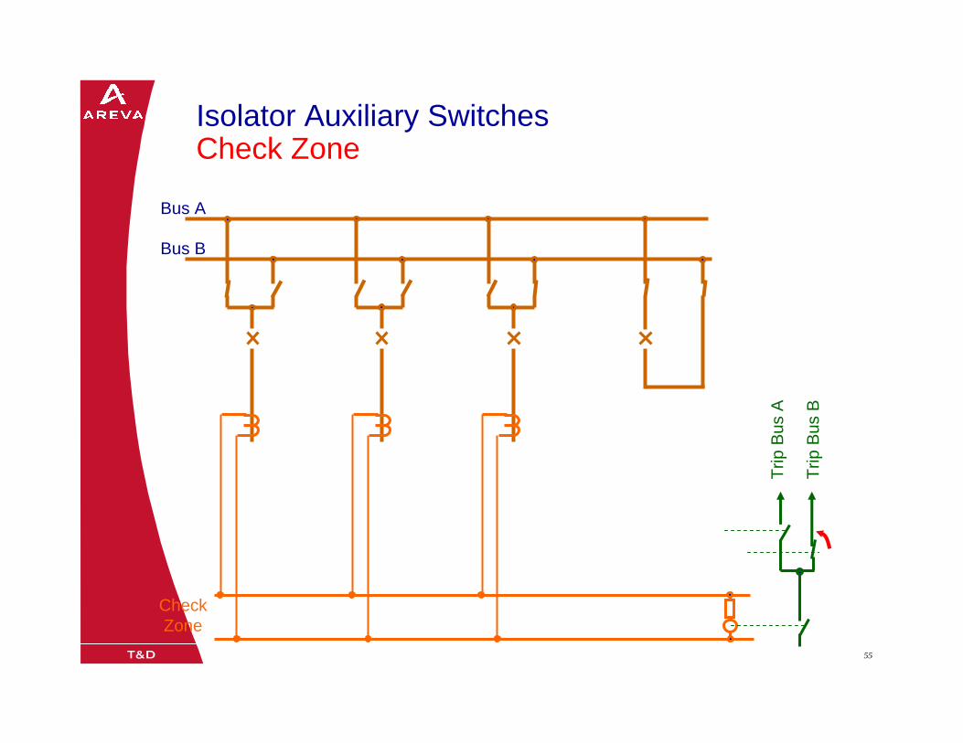
08/0205/02/0355 55
Bus A
Bus B
Trip
Bus
A
Trip
Bus
B
Check Zone
Isolator Auxiliary Switches Check Zone
08/0205/02/0356 5608/0205/02/0356
One Breaker and a Half Substation
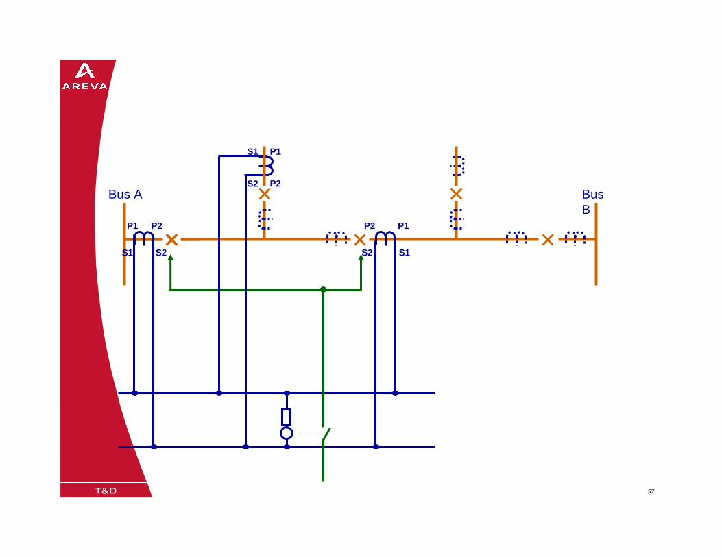
08/0205/02/0357 57
Bus A Bus B
P1
P2
S1
S2
P1
S1
P2
S2
P1P2
S1S2
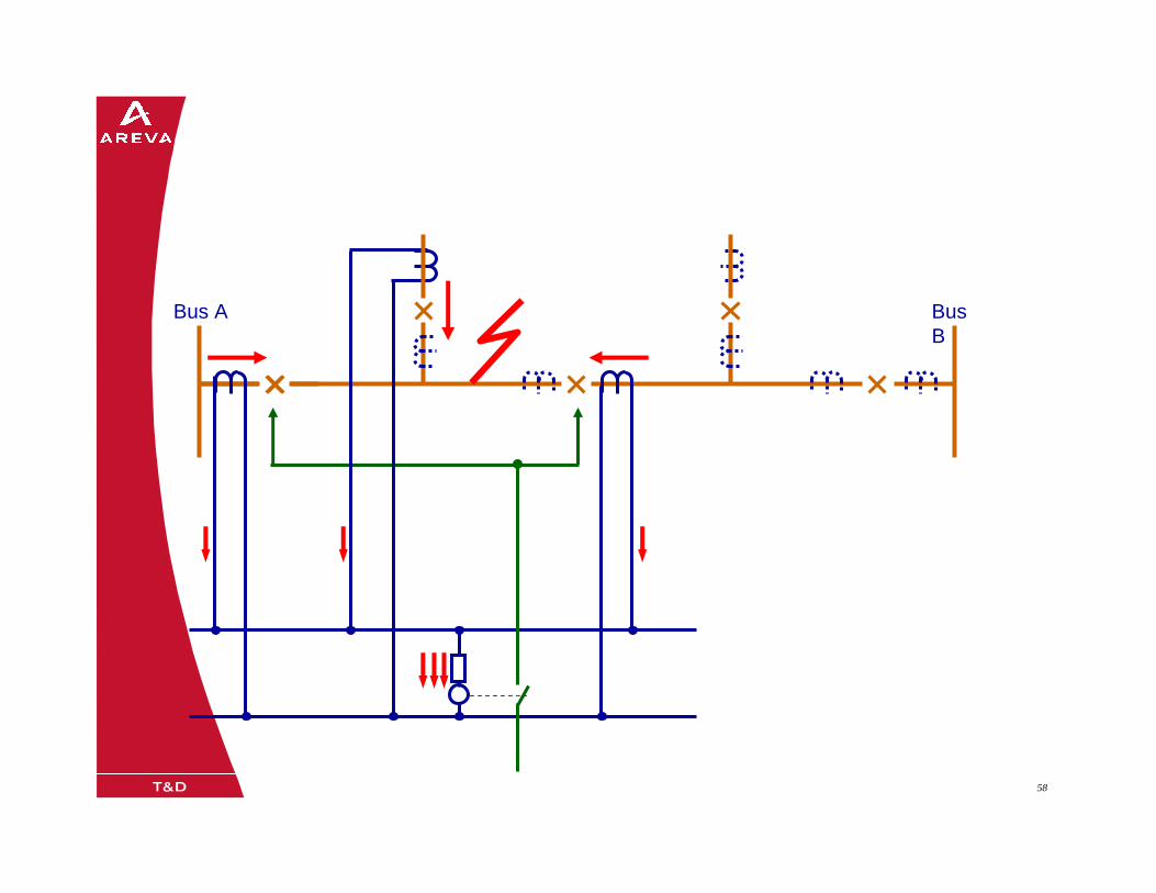
08/0205/02/0358 58
Bus A Bus B
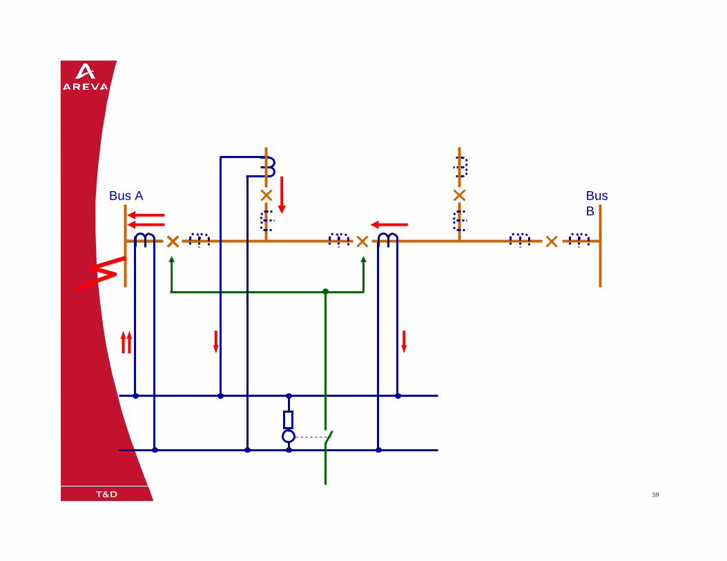
08/0205/02/0359 59
Bus A Bus B
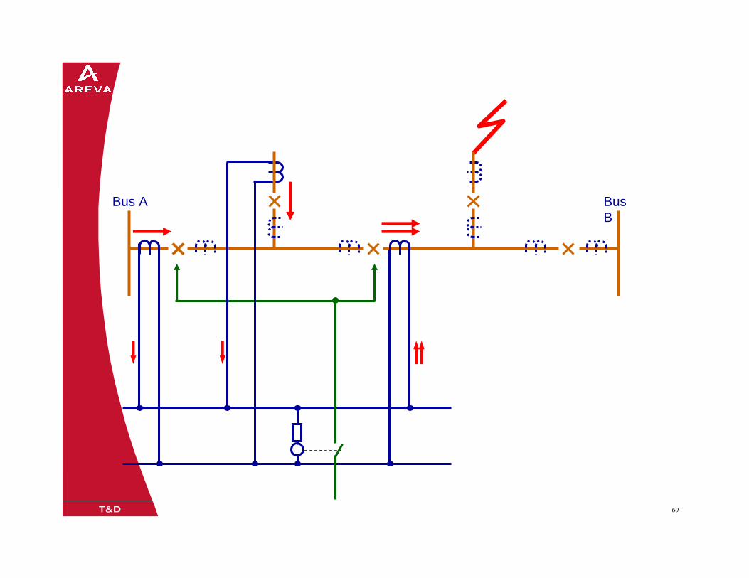
08/0205/02/0360 60
Bus A Bus B
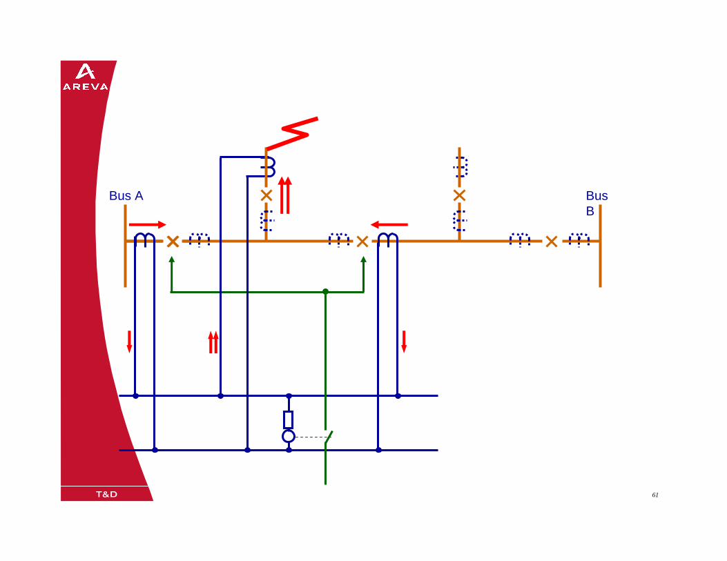
08/0205/02/0361 61
Bus A Bus B
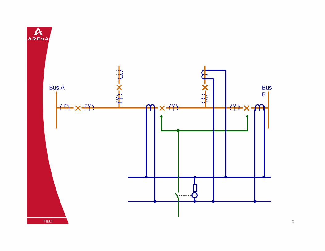
08/0205/02/0362 62
Bus A Bus B
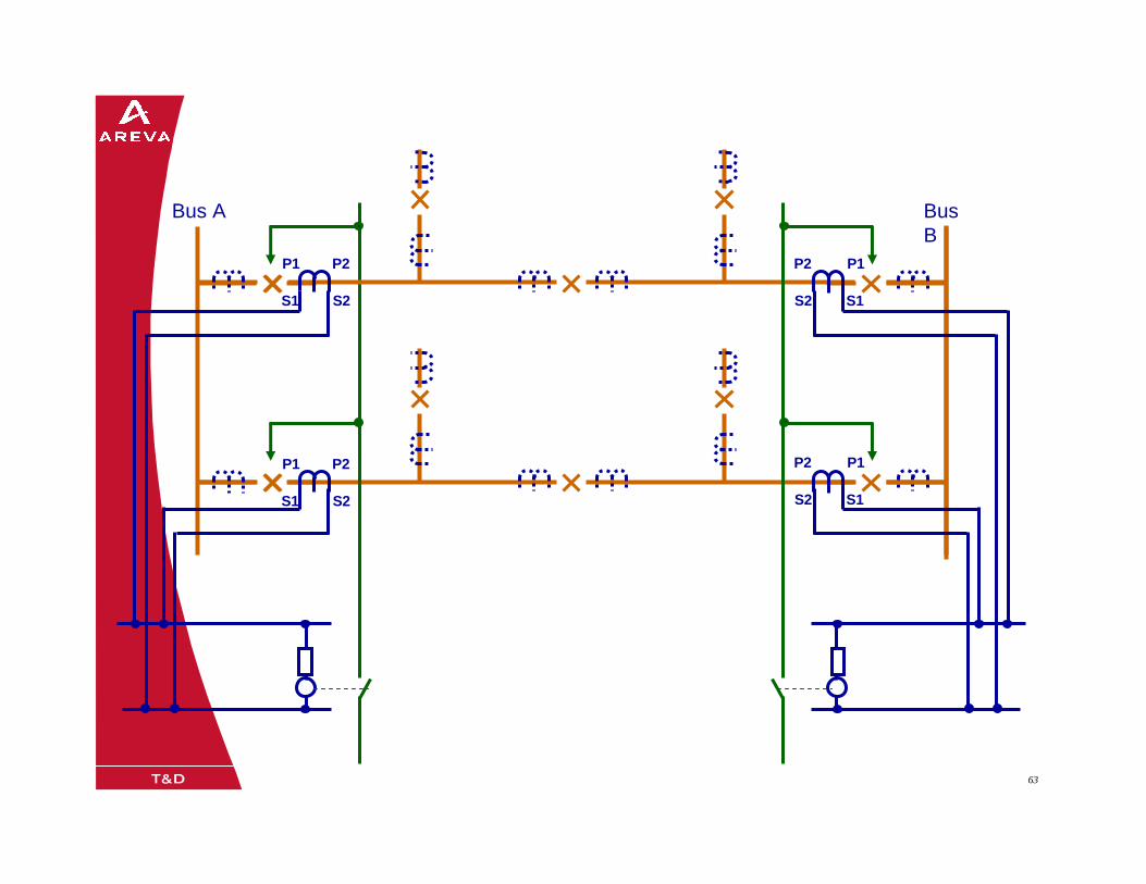
08/0205/02/0363 63
Bus A Bus B
P1
S1
P2
S2
P1
S1
P2
S2
P1
S1
P2
S2
P1
S1
P2
S2