
doc.: IEEE 802.11-05/0562r0 · Web view... 1 1 1 4 4 2 1 1 4 4 ID Length Version Active Protocol ID...
207
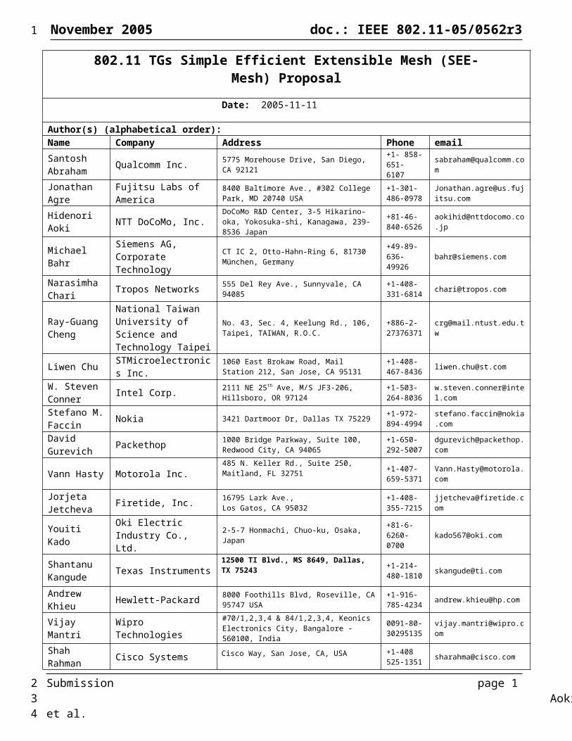
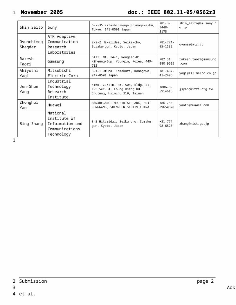
November 2005 doc.: IEEE 802.11-05/0562r3 802.11 TGs Simple Efficient Extensible Mesh (SEE- Mesh) Proposal Date: 2005-11-11 Author(s) (alphabetical order): Name Company Address Phone email Santosh Abraham Qualcomm Inc. 5775 Morehouse Drive, San Diego, CA 92121 +1- 858- 651- 6107 [email protected] m Jonathan Agre Fujitsu Labs of America 8400 Baltimore Ave., #302 College Park, MD 20740 USA +1-301- 486-0978 [email protected] itsu.com Hidenori Aoki NTT DoCoMo, Inc. DoCoMo R&D Center, 3-5 Hikarino- oka, Yokosuka-shi, Kanagawa, 239- 8536 Japan +81-46- 840-6526 [email protected] .jp Michael Bahr Siemens AG, Corporate Technology CT IC 2, Otto-Hahn-Ring 6, 81730 München, Germany +49-89- 636- 49926 [email protected] Narasimha Chari Tropos Networks 555 Del Rey Ave., Sunnyvale, CA 94085 +1-408- 331-6814 [email protected] Ray-Guang Cheng National Taiwan University of Science and Technology Taipei No. 43, Sec. 4, Keelung Rd., 106, Taipei, TAIWAN, R.O.C. +886-2- 27376371 [email protected] w Liwen Chu STMicroelectronic s Inc. 1060 East Brokaw Road, Mail Station 212, San Jose, CA 95131 +1-408- 467-8436 [email protected] W. Steven Conner Intel Corp. 2111 NE 25 th Ave, M/S JF3-206, Hillsboro, OR 97124 +1-503- 264-8036 w.steven.conner@inte l.com Stefano M. Faccin Nokia 3421 Dartmoor Dr, Dallas TX 75229 +1-972- 894-4994 stefano.faccin@nokia .com David Gurevich Packethop 1000 Bridge Parkway, Suite 100, Redwood City, CA 94065 +1-650- 292-5007 dgurevich@packethop. com Vann Hasty Motorola Inc. 485 N. Keller Rd., Suite 250, Maitland, FL 32751 +1-407- 659-5371 Vann.Hasty@motorola. com Jorjeta Jetcheva Firetide, Inc. 16795 Lark Ave., Los Gatos, CA 95032 +1-408- 355-7215 [email protected] om Youiti Kado Oki Electric Industry Co., Ltd. 2-5-7 Honmachi, Chuo-ku, Osaka, Japan +81-6- 6260- 0700 [email protected] Shantanu Kangude Texas Instruments 12500 TI Blvd., MS 8649, Dallas, TX 75243 +1-214- 480-1810 [email protected] Andrew Khieu Hewlett-Packard 8000 Foothills Blvd, Roseville, CA 95747 USA +1-916- 785-4234 [email protected] Vijay Mantri Wipro Technologies #70/1,2,3,4 & 84/1,2,3,4, Keonics Electronics City, Bangalore - 560100, India 0091-80- 30295135 [email protected] om Shah Rahman Cisco Systems Cisco Way, San Jose, CA, USA +1-408 525-1351 [email protected] Submission page 1 Aoki et al. 1 2 3 4
Transcript of doc.: IEEE 802.11-05/0562r0 · Web view... 1 1 1 4 4 2 1 1 4 4 ID Length Version Active Protocol ID...
November 2005 doc.: IEEE 802.11-05/0562r3
802.11 TGs Simple Efficient Extensible Mesh (SEE-Mesh) Proposal
Date: 2005-11-11
Author(s) (alphabetical order):Name Company Address Phone emailSantosh Abraham Qualcomm Inc. 5775 Morehouse Drive, San Diego, CA 92121 +1- 858-
651- 6107 [email protected]
Jonathan Agre Fujitsu Labs of America 8400 Baltimore Ave., #302 College Park, MD 20740 USA
+1-301- 486-0978 [email protected]
Hidenori Aoki NTT DoCoMo, Inc. DoCoMo R&D Center, 3-5 Hikarino-oka, Yokosuka-shi, Kanagawa, 239-8536 Japan
+81-46-840-6526 [email protected]
Michael Bahr Siemens AG,Corporate Technology
CT IC 2, Otto-Hahn-Ring 6, 81730 München, Germany
+49-89-636-49926 [email protected]
Narasimha Chari Tropos Networks 555 Del Rey Ave., Sunnyvale, CA 94085 +1-408-331-
6814 [email protected]
Ray-Guang Cheng
National Taiwan University of Science and Technology Taipei
No. 43, Sec. 4, Keelung Rd., 106, Taipei, TAIWAN, R.O.C.
+886-2-27376371 [email protected]
Liwen Chu STMicroelectronics Inc. 1060 East Brokaw Road, Mail Station 212, San Jose, CA 95131
+1-408-467-8436 [email protected]
W. Steven Conner Intel Corp. 2111 NE 25th Ave, M/S JF3-206, Hillsboro, OR
97124+1-503-264-8036 [email protected]
Stefano M. Faccin Nokia 3421 Dartmoor Dr, Dallas TX 75229 +1-972-894-
4994 [email protected]
David Gurevich Packethop 1000 Bridge Parkway, Suite 100, Redwood City,
CA 94065+1-650-292-5007 [email protected]
Vann Hasty Motorola Inc.485 N. Keller Rd., Suite 250, Maitland, FL 32751 +1-407-659-
5371 [email protected]
Jorjeta Jetcheva Firetide, Inc. 16795 Lark Ave.,
Los Gatos, CA 95032+1-408-355-7215 [email protected]
Youiti Kado Oki Electric Industry Co., Ltd. 2-5-7 Honmachi, Chuo-ku, Osaka, Japan +81-6-6260-
0700 [email protected]
Shantanu Kangude Texas Instruments
12500 TI Blvd., MS 8649, Dallas, TX 75243 +1-214-480-1810 [email protected]
Andrew Khieu Hewlett-Packard 8000 Foothills Blvd, Roseville, CA 95747 USA +1-916-785-4234 [email protected]
Vijay Mantri Wipro Technologies #70/1,2,3,4 & 84/1,2,3,4, Keonics Electronics City, Bangalore - 560100, India
0091-80-30295135 [email protected]
Shah Rahman Cisco SystemsCisco Way, San Jose, CA, USA +1-408 525-
1351 [email protected]
Shin Saito Sony 6-7-35 Kitashinawaga Shinagawa-ku, Tokyo, 141-0001 Japan
+81-3-5448-3175
Oyunchimeg Shagdar
ATR Adaptive Communication Research Laboratories
2-2-2 Hikaridai, Seika-cho, Soraku-gun, Kyoto, Japan
+81-774-95-1532 [email protected]
Rakesh Taori Samsung SAIT, Mt. 14-1, Nongseo-Ri Kiheung-Eup, Youngin, Korea, 449-712
+82 31 280 9635 [email protected]
Akiyoshi Yagi Mitsubishi Electric Corp. 5-1-1 Ofuna, Kamakura, Kanagawa, 247-8501 Japan
+81-467-41-2406 [email protected]
Jen-Shun Yang Industrial Technology Research Institute
K100, CL/ITRI Rm. 505, Bldg. 51, 195 Sec. 4, Chung Hsing Rd. Chutung, Hsinchu 310, Taiwan
+886-3-5914616 [email protected]
Zhonghui Yao Huawei BANXUEGANG INDUSTRIAL PARK, BUJI LONGGANG, SHENZHEN 518129 CHINA
+86 755 89650528 [email protected]
Bing Zhang
National Institute of Information and Communications Technology
3-5 Hikaridai, Seika-cho, Soraku-gun, Kyoto, Japan
+81-774-98-6820 [email protected]
Submission page 1 Aoki, et al.
1
1
2
November 2005 doc.: IEEE 802.11-05/0562r3
Submission page 2 Aoki, et al.
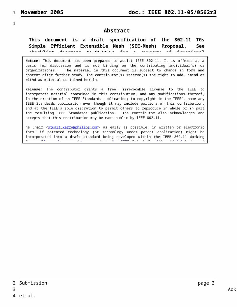
AbstractThis document is a draft specification of the 802.11 TGs Simple Efficient Extensible Mesh (SEE-Mesh) Proposal. See checklist document 11-05/0563 for a summary of functional requirements and scope topics covered by this proposal.
Notice: This document has been prepared to assist IEEE 802.11. It is offered as a basis for discussion and is not binding on the contributing individual(s) or organization(s). The material in this document is subject to change in form and content after further study. The contributor(s) reserve(s) the right to add, amend or withdraw material contained herein.
Release: The contributor grants a free, irrevocable license to the IEEE to incorporate material contained in this contribution, and any modifications thereof, in the creation of an IEEE Standards publication; to copyright in the IEEE’s name any IEEE Standards publication even though it may include portions of this contribution; and at the IEEE’s sole discretion to permit others to reproduce in whole or in part the resulting IEEE Standards publication. The contributor also acknowledges and accepts that this contribution may be made public by IEEE 802.11.
Patent Policy and Procedures: The contributor is familiar with the IEEE 802 Patent Policy and Procedures <http:// ieee802.org/guides/bylaws/sb-bylaws.pdf>, including the statement "IEEE standards may include the known use of patent(s), including patent applications, provided the IEEE receives assurance from the patent holder or applicant with respect to patents essential for compliance with both mandatory and optional portions of the standard." Early disclosure to the Working Group of patent information that might be relevant to the standard is essential to reduce the possibility for delays in the development process and increase the likelihood that the draft publication will be approved for publication. Please notify the Chair <[email protected]> as early as possible, in written or electronic form, if patented technology (or technology under patent application) might be incorporated into a draft standard being developed within the IEEE 802.11 Working Group. If you have questions, contact the IEEE Patent Committee Administrator at <[email protected]>.
1
1
2
November 2005 doc.: IEEE 802.11-05/0562r3
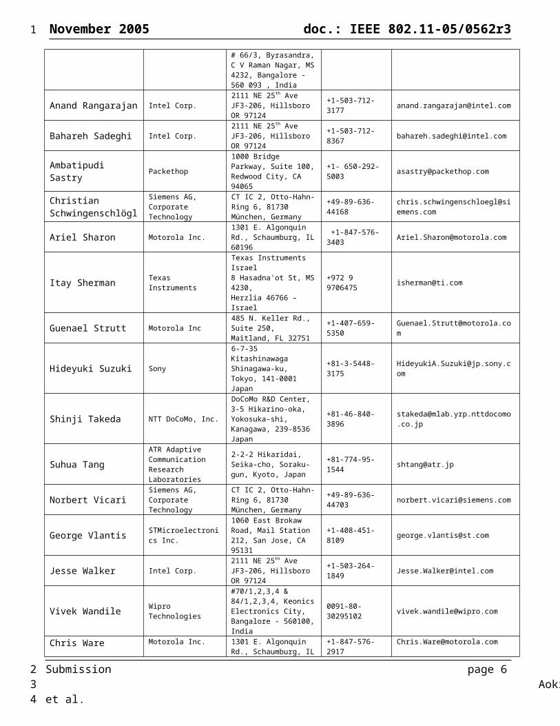
Contributors (alphabetical order)
Name Company Address Phone EmailMalik Audeh Tropos Networks 555 Del Rey Ave,
Sunnyvale, CA 94085 +1 (408) 331-6834 [email protected]
Amit Bansal Wipro Technologies#70/1,2,3,4 & 84/1,2,3,4, Keonics Electronics City, Bangalore - 560100, India
0091-80-30295128 [email protected]
Anuj Batra Texas Instruments 12500 TI Blvd., MS 8649, Dallas, TX 75243 +1-214-480-4220 [email protected]
Wei-Peng Chen Fujitsu Laboratories of America
1240 E. Arques Ave. Sunnyvale, CA 00180 USA +1-408-530 4622 [email protected]
Harshal Chhaya Texas Instruments 12500 TI Blvd., MS 8649, Dallas, TX 75243 +1-214-480-6995 [email protected]
SongYean Cho Samsung
416, Maetan-3dong, Yeongtong-gu,Suwon-Si, Gyeonggi-do, Korea 443-742
+82 31 277 7534 [email protected]
Steve Emeott Motorola Inc. 1301 E. Algonquin Rd., Schaumburg, IL 60196 +1 (847) 576-8268 [email protected]
Michael Finkenzeller Siemens AG,Corporate Technology
CT IC 2, Otto-Hahn-Ring 6, 81730 München, Germany +49-89-636-42725 [email protected]
Mario Gerla UCLA (collaboration with STMicro)
UCLA Computer Science Department, BH 3732F, Los Angeles, CA 90095-1596
+1-310-825-4367 [email protected]
Hrishikesh Gossain Motorola Inc. 485 N. Keller Rd., Suite 250, Maitland, FL 32751 +1-407-659-5393 [email protected]
Masaaki Isozu Sony6-7-35 Kitashinawaga Shinagawa-ku, Tokyo, 141-0001 Japan
+81-3-5448-3175 [email protected]
Avinash Joshi Motorola Inc. 485 N. Keller Rd., Suite 250, Maitland, FL 32751 +1-407-659-5398 [email protected]
Tarun Joshi Motorola Inc. 485 N. Keller Rd., Suite 250, Maitland, FL 32751 +1-407-659-5359 [email protected]
HyeongSeok Kim Samsung
416, Maetan-3dong, Yeongtong-gu,Suwon-Si, Gyeonggi-do, Korea 443-742
+82 31 277 7534 [email protected]
Kyeong-Soo Kim STMicroelectronics Inc.1060 East Brokaw Road, Mail Station 212, San Jose, CA 95131
+1-408-621-4913 [email protected]
MinSoo Kim Samsung
416, Maetan-3dong, Yeongtong-gu,Suwon-Si, Gyeonggi-do, Korea 443-742
+82 31 277 7535 [email protected]
Jarkko Kneckt Nokia Rakentajainrinne 6, 02330 Espoo, Finland +358504821550 [email protected]
Jan Kruys Cisco Systems International
Haarlerbergweg, 1101CHAmsterdam, Netherlands +31 20357 2447 [email protected]
Matthias Kutschen-reuter
Siemens AG,Corporate Technology
CT IC 2, Otto-Hahn-Ring 6, 81730 München, Germany +49-89-636-51744 [email protected]
Sung-Won Lee Samsung SAIT, Mt. 14-1, Nongseo-Ri Kiheung-Eup, Youngin, Korea 449-712
+82 31 280 9628 [email protected]
Yeng-Zhong Lee UCLA (collaboration with STMicro)
UCLA Computer Science Department, BH 3803A, 420 Westwood Plaza, Los Angeles, CA 90095
+1-310-206-3212 [email protected]
Guoqing Li Intel Corp. 2111 NE 25th Ave., Hillsboro, OR 97124 +1-503-712-2089 [email protected]
Daniela Maniezzo UCLA (collaboration with STMicro)
UCLA Computer Science Department, BH 3803A, 420 Westwood Plaza,Los Angeles, CA 90095
+1-310-206-3212 [email protected]
Art Martin Intel Corp. 2111 NE 25th Ave JF3-206, Hillsboro OR 97124 +1-503-264-9261 [email protected]
Yoichi Matsumoto NTT DoCoMo, Inc.DoCoMo R&D Center, 3-5 Hikarino-oka, Yokosuka-shi, Kanagawa, 239-8536 Japan
+81-46-840-3894 [email protected]
Benjamin Metzler Intel Corp. 2111 NE 25th Ave JF3-206, Hillsboro OR 97124 +1-503-264-4679 [email protected]
Submission page 3 Aoki, et al.
1
1
2

November 2005 doc.: IEEE 802.11-05/0562r3
Masanori Nozaki Oki Electric Industry Co., Ltd.
2-5-7 Honmachi, Chuo-ku, Osaka, Japan +81-6-6260-0700 [email protected]
Bob O’Hara Cisco Systems 3625 Cisco Way, San Jose, CA 95134 +1-408-853-5513 [email protected]
Sebnem Ozer Motorola Inc. 485 N. Keller Rd., Suite 250, Maitland, FL 32751 +1-407-659-5391 [email protected]
Joon-Sang Park UCLA (collaboration with STMicro)
UCLA Computer Science Department, BH 3803A, 420 Westwood Plaza,Los Angeles, CA 90095
+1-310-206-3212 [email protected]
Neeraj Poojary Texas Instruments 165 Gibraltar Ct, MS 4126,Sunnyvale, CA 94089 +1-408-543-5305 [email protected]
Shyamal Ramachandran Motorola Inc 485 N. Keller Rd., Suite
250, Maitland, FL 32751 +1-407-659-5354 [email protected]
Sridhar Ramesh Texas Instruments
Texas Instruments (India) Pvt. Ltd., Bagmane Tech Park, # 66/3, Byrasandra, C V Raman Nagar, MS 4232, Bangalore - 560 093 , India
+91-80-25048173 [email protected]
Anand Rangarajan Intel Corp. 2111 NE 25th Ave JF3-206, Hillsboro OR 97124 +1-503-712-3177 [email protected]
Bahareh Sadeghi Intel Corp. 2111 NE 25th Ave JF3-206, Hillsboro OR 97124 +1-503-712-8367 [email protected]
Ambatipudi Sastry Packethop1000 Bridge Parkway, Suite 100, Redwood City, CA 94065
+1- 650-292-5003 [email protected]
Christian Schwingen-schlögl
Siemens AG,Corporate Technology
CT IC 2, Otto-Hahn-Ring 6, 81730 München, Germany +49-89-636-44168 [email protected]
Ariel Sharon Motorola Inc. 1301 E. Algonquin Rd., Schaumburg, IL 60196 +1-847-576-3403 [email protected]
Itay Sherman Texas InstrumentsTexas Instruments Israel8 Hasadna'ot St, MS 4230,Herzlia 46766 – Israel
+972 9 9706475 [email protected]
Guenael Strutt Motorola Inc 485 N. Keller Rd., Suite 250, Maitland, FL 32751 +1-407-659-5350 [email protected]
Hideyuki Suzuki Sony6-7-35 Kitashinawaga Shinagawa-ku, Tokyo, 141-0001 Japan
+81-3-5448-3175 [email protected]
Shinji Takeda NTT DoCoMo, Inc.DoCoMo R&D Center, 3-5 Hikarino-oka, Yokosuka-shi, Kanagawa, 239-8536 Japan
+81-46-840-3896 [email protected]
Suhua TangATR Adaptive Communication Research Laboratories
2-2-2 Hikaridai, Seika-cho, Soraku-gun, Kyoto, Japan +81-774-95-1544 [email protected]
Norbert Vicari Siemens AG,Corporate Technology
CT IC 2, Otto-Hahn-Ring 6, 81730 München, Germany +49-89-636-44703 [email protected]
George Vlantis STMicroelectronics Inc.1060 East Brokaw Road, Mail Station 212, San Jose, CA 95131
+1-408-451-8109 [email protected]
Jesse Walker Intel Corp. 2111 NE 25th Ave JF3-206, Hillsboro OR 97124 +1-503-264-1849 [email protected]
Vivek Wandile Wipro Technologies#70/1,2,3,4 & 84/1,2,3,4, Keonics Electronics City, Bangalore - 560100, India
0091-80-30295102 [email protected]
Chris Ware Motorola Inc. 1301 E. Algonquin Rd., Schaumburg, IL 60196 +1-847-576-2917 [email protected]
Carl Wijting Nokia Itämerenkatu 11-13, 00180 Helsinki, Finland +358 50 486 0564 [email protected]
Marcus Wong SamsungSteinman Hall, #549, 140 Street & Convent Avenue, New York, NY 10031
+1 212 650 7187 [email protected]
Ariton Xhafa Texas Instruments 12500 TI Blvd., MS 8649, Dallas, TX 75243 +1-214-480-6556 [email protected]
Akira Yamada NTT DoCoMo, Inc.DoCoMo R&D Center, 3-5 Hikarino-oka, Yokosuka-shi, Kanagawa, 239-8536 Japan
+81-46-840-6527 [email protected]
Lily Yang Intel Corp. 2111 NE 25th Ave JF3-206, Hillsboro OR 97124 +1-503-264-8813 [email protected]
Mark Yarvis Intel Corp. 2111 NE 25th Ave JF3-206, Hillsboro OR 97124 +1-503-264-7469 [email protected]
Surong Zeng Motorola Inc. 485 N. Keller Rd., Suite +1-407-659-5312 [email protected]
Submission page 4 Aoki, et al.
1
2

November 2005 doc.: IEEE 802.11-05/0562r3
250, Maitland, FL 32751
Heyun Zheng Motorola Inc. 485 N. Keller Rd., Suite 250, Maitland, FL 32751 +1-407-659-5361 [email protected]
DedicationThis proposal is dedicated to the memory of Art Martin who passed away while contributing to it. The authors and contributors appreciate his relentless efforts towards the development of a mesh standard for 802.11.
Revision HistoryRevision Comments DateR0 Initial proposal release for June 15, 2005 submission deadline. 2005-06-15R1 Updated proposal release for September 12, 2005 submission deadline.
Primary changes since last version:o Updated default routing protocol to HWMPo Added common channel frameworko Various editorial improvements
2005-09-12
R2 Updated proposal release for November 7, 2005 submission deadline.Primary changes since last version:
o Added mesh beaconing and synchronizationo Reorganization of sec. 6.3 “Mesh Topology Discovery and
Formation”o Various editorial improvements
2005-11-07
R3 Editorial updates to the proposal:o Improved texts for HWMP, the default routing protocol, in sec.
6.4.3.1o Updated author and contributor lists
2005-11-11
Submission page 5 Aoki, et al.
1
123
4
5
2
November 2005 doc.: IEEE 802.11-05/0562r3
Table of ContentsDedication.................................................................................................................................................................................5Revision History........................................................................................................................................................................5
1 Executive Summary............................................................................................................................................................132 Definitions...........................................................................................................................................................................133 Abbreviations and Acronyms..............................................................................................................................................144 General Description.............................................................................................................................................................16
4.1 Motivation...................................................................................................................................................................164.2 WLAN Mesh Overview..............................................................................................................................................16
4.2.1 Rationale..............................................................................................................................................................164.2.2 Operational Modes..............................................................................................................................................16
4.2.2.1 Lightweight mesh point operation...................................................................................................................184.2.2.2 Non-forwarding mesh point operation (Informative)......................................................................................184.2.2.3 Support for Power Saving Devices in a WLAN Mesh....................................................................................18
4.2.3 Multi-Channel Operation in a WLAN Mesh.......................................................................................................184.2.3.1 RF Channel Interfaces and Unified Channel Graphs......................................................................................194.2.3.2 Common Channel Framework........................................................................................................................194.2.3.3 Common Channel Selection............................................................................................................................20
4.2.4 Interconnecting WLAN Mesh with other Networks...........................................................................................214.2.4.1 General Interworking......................................................................................................................................214.2.4.2 Reference Model for WLAN Mesh Interworking...........................................................................................224.2.4.3 MAC Data Transport over a WLAN Mesh.....................................................................................................23
5 MAC Frame Formats..........................................................................................................................................................235.1 Mesh Data Frames.......................................................................................................................................................23
5.1.1 Mesh Forwarding Control field...........................................................................................................................235.1.1.1 Mesh TTL field...............................................................................................................................................245.1.1.2 Mesh E2E Sequence number field..................................................................................................................24
5.2 Frame Fields................................................................................................................................................................245.2.1 More data field....................................................................................................................................................24
5.3 Mesh Management Frames.........................................................................................................................................245.3.1 Specific Management Frame Types....................................................................................................................24
5.3.1.1 Beacon frame format.......................................................................................................................................245.3.1.2 Association Request frame format..................................................................................................................255.3.1.3 Reassociation Request frame format...............................................................................................................265.3.1.4 Probe Request frame format............................................................................................................................265.3.1.5 Probe Response frame format.........................................................................................................................26
5.3.2 Management frame body components................................................................................................................275.3.2.1 Action field......................................................................................................................................................27
5.3.3 Information elements...........................................................................................................................................275.3.3.1 WLAN Mesh Capability Element...................................................................................................................275.3.3.2 Active Profile Announcement Element...........................................................................................................315.3.3.3 Mesh ID Element............................................................................................................................................315.3.3.4 Local Link state announcement Element........................................................................................................325.3.3.5 HWMP Information Elements........................................................................................................................325.3.3.6 OFDM Parameter Element..............................................................................................................................355.3.3.7 Target Transmission Rate Element.................................................................................................................365.3.3.8 Offered Traffic Load Element.........................................................................................................................365.3.3.9 Neighborhood Congestion Element................................................................................................................365.3.3.10 MP Peer Request Element...........................................................................................................................375.3.3.11 MP Peer Response Element........................................................................................................................375.3.3.12 Mesh Portal Reachability Element..............................................................................................................385.3.3.13 Mesh Portal/Root Announcement Element.................................................................................................385.3.3.14 Channel Cluster Switch Announcement element........................................................................................405.3.3.15 Neighbor List element.................................................................................................................................405.3.3.16 DTIM element.............................................................................................................................................415.3.3.17 Beacon Timing element..............................................................................................................................42
5.3.4 Action frame format details.................................................................................................................................445.3.4.1 Mesh management action details....................................................................................................................44
Submission page 6 Aoki, et al.
1
123456789
10111213141516171819202122232425262728293031323334353637383940414243444546474849505152535455565758
2

November 2005 doc.: IEEE 802.11-05/0562r3
5.3.4.2 Local Link State Announcement frame format...............................................................................................445.3.4.3 Route Request frame format...........................................................................................................................455.3.4.4 Route Reply frame format...............................................................................................................................455.3.4.5 Route Error frame format................................................................................................................................455.3.4.6 Route Reply Ack frame format.......................................................................................................................465.3.4.7 Congestion Control Request frame format......................................................................................................465.3.4.8 Congestion Control Response frame format...................................................................................................465.3.4.9 Neighborhood Congestion Announcement frame format...............................................................................475.3.4.10 Legacy Action Encapsulation frame format................................................................................................475.3.4.11 Vender Specific Mesh Management frame format.....................................................................................48
5.4 Mesh Control Frames..................................................................................................................................................485.4.1 Request to Switch (RTX) frame format..............................................................................................................485.4.2 Clear to Switch (CTX) frame format..................................................................................................................48
6 WLAN Mesh Services........................................................................................................................................................496.1 Use of Mesh Identifier.................................................................................................................................................496.2 Single and Multiple Radio Devices.............................................................................................................................496.3 Mesh Topology Discovery and Formation..................................................................................................................49
6.3.1 Topology Discovery............................................................................................................................................496.3.1.1 Profiles for Extensibility of Path Selection Protocol and Metric....................................................................496.3.1.2 Neighbor Discovery........................................................................................................................................49
6.3.2 Mesh Link Operations.........................................................................................................................................506.3.2.1 Peer Link Setup...............................................................................................................................................506.3.2.2 Local Link State Discovery.............................................................................................................................516.3.2.3 Mesh Portal Discovery (Optional)..................................................................................................................52
6.3.3 Channel Selection................................................................................................................................................526.3.3.1 Channel Selection Modes for Mesh Point Logical Radio Interfaces..............................................................526.3.3.2 Simple Channel Unification Protocol.............................................................................................................526.3.3.3 Channel Cluster Switch Protocol....................................................................................................................52
6.3.4 MP Boot Sequence (Informative).......................................................................................................................536.3.5 MP Tables (Informative).....................................................................................................................................54
6.3.5.1 MP Neighbor Table.........................................................................................................................................546.3.5.2 MP Proxy Table (Informative)........................................................................................................................55
6.4 Mesh Path Selection and Forwarding..........................................................................................................................566.4.1 Overview.............................................................................................................................................................56
6.4.1.1 Extensible Path Selection Framework.............................................................................................................566.4.2 Path Selection Metrics.........................................................................................................................................57
6.4.2.1 Airtime Link Metric Function Computation Procedures................................................................................576.4.3 Path Selection Protocol.......................................................................................................................................58
6.4.3.1 Hybrid Wireless Mesh Protocol (HWMP): Default path selection protocol for interoperability...................586.4.3.2 Radio Aware OLSR Path Selection Protocol (Optional)................................................................................71
6.4.4 Data Message Forwarding...................................................................................................................................956.4.4.1 MSDU Ordering..............................................................................................................................................956.4.4.2 Unicast Forwarding of Four-Address Frames.................................................................................................956.4.4.3 Unicast Forwarding of Three-Address Frames...............................................................................................956.4.4.4 Broadcast Forwarding of Four-Address Frames.............................................................................................966.4.4.5 Multicast Forwarding of Four-Address Frames..............................................................................................96
6.5 Security........................................................................................................................................................................966.5.1 Security Framework............................................................................................................................................96
6.5.1.1 RSNA Establishment.......................................................................................................................................976.5.1.2 Centralized 802.1X Authentication Model.....................................................................................................976.5.1.3 Distributed 802.1X Authentication Model......................................................................................................986.5.1.4 Pre-Shared Key Authentication Model...........................................................................................................99
6.5.2 Extensible AKM (Informative).........................................................................................................................1006.5.3 Mesh Management Frame Security...................................................................................................................100
6.5.3.1 Forgery Protection.........................................................................................................................................1006.5.3.2 Confidentiality protection.............................................................................................................................1006.5.3.3 Compatibility with 802.11i/r key hierarchy..................................................................................................1006.5.3.4 Incremental inclusion of new management frames.......................................................................................1006.5.3.5 Protection only after key establishment........................................................................................................100
Submission page 7 Aoki, et al.
1
123456789
1011121314151617181920212223242526272829303132333435363738394041424344454647484950515253545556575859
2
November 2005 doc.: IEEE 802.11-05/0562r3
6.5.3.6 Fragmentation support for management frames............................................................................................1016.5.3.7 Mesh Specific Requirements.........................................................................................................................1016.5.3.8 Management Frames sent pre-Authentication...............................................................................................1016.5.3.9 Management Frames sent post-Authentication.............................................................................................101
6.6 Optimizations to EDCA for Mesh Point...................................................................................................................1016.6.1 Recommendation for NAV Duration Setting (Informative).............................................................................1016.6.2 Forwarding and BSS Traffic Interaction (Informative)....................................................................................102
6.7 Intra-Mesh Congestion Control.................................................................................................................................1036.7.1 Motivation (Informative)...................................................................................................................................1036.7.2 Local Congestion Monitoring (Informative).....................................................................................................1046.7.3 Congestion Control Signaling...........................................................................................................................1046.7.4 Target Rate Computation (Informative)............................................................................................................1056.7.5 Local Rate Control Mechanism (Informative)..................................................................................................105
6.8 Multi-Channel MAC Using Common Channel Framework (Optional)...................................................................1066.8.1 Channel Coordination Mechanism....................................................................................................................1076.8.2 Handling different traffic scenarios in a mesh network....................................................................................108
6.9 Interworking Support in a WLAN Mesh...................................................................................................................1106.9.1 Overview of Interworking in a WLAN Mesh...................................................................................................1106.9.2 Basic Layer-2 Bridging for a WLAN Mesh with Layer-2 Path Selection........................................................110
6.9.2.1 Mesh Point Forwarding Table (Informative)................................................................................................1116.9.2.2 Determining if a Destination is Inside/Outside the Mesh.............................................................................1116.9.2.3 Data Packet Forwarding................................................................................................................................1126.9.2.4 Maintaining Conformance with a Dynamic Bridging Protocol at MPPs (Informative)...............................113
6.9.3 VLAN support in a WLAN Mesh.....................................................................................................................1146.10 Configuration and Management................................................................................................................................115
6.10.1 Support for DFS in a WLAN Mesh..................................................................................................................1156.11 Mesh Beaconing and Synchronization......................................................................................................................115
6.11.1 Synchronization.................................................................................................................................................1156.11.1.1 Unsynchronizing MPs...............................................................................................................................1156.11.1.2 Synchronizing MPs (Optional)..................................................................................................................1156.11.1.3 Interaction between synchronizing and unsynchronizing MPs.................................................................116
6.11.2 Beaconing..........................................................................................................................................................1166.11.2.1 Beaconing by unsynchronizing MPs.........................................................................................................1166.11.2.2 Beaconing by synchronizing MPs.............................................................................................................1166.11.2.3 Designated Beacon Broadcaster................................................................................................................117
6.11.3 Mesh Beacon Collision Avoidance (MBCA) mechanism................................................................................1186.11.3.1 Action frames for beacon timing request and response............................................................................118
6.12 Power Management in a Mesh (Optional)................................................................................................................1206.12.1 Basic approach..................................................................................................................................................1206.12.2 Initialization of power management within a mesh..........................................................................................1206.12.3 Mesh point power state transitions....................................................................................................................1216.12.4 Frame transmission...........................................................................................................................................1216.12.5 Power management operation with APSD........................................................................................................1226.12.6 Power Save parameters selection......................................................................................................................1226.12.7 TS Reinstatement..............................................................................................................................................1236.12.8 Beacon broadcaster...........................................................................................................................................123
6.12.8.1 Change of Beacon broadcaster..................................................................................................................1236.12.8.2 Beacon broadcaster power save state........................................................................................................123
6.12.9 Naive Mesh operation (Informative).................................................................................................................1236.13 Layer Management (Informative).............................................................................................................................124
6.13.1 Principles of Operation......................................................................................................................................1256.13.2 Inter-Layer Management...................................................................................................................................1256.13.3 Re-transmit Process...........................................................................................................................................1256.13.4 Filtering database..............................................................................................................................................1256.13.5 Forwarding database.........................................................................................................................................1266.13.6 Learning cache..................................................................................................................................................1266.13.7 Protocol entity...................................................................................................................................................1266.13.8 Service Primitives.............................................................................................................................................126
6.13.8.1 MLME-SendMeshMgmt.request..............................................................................................................126
Submission page 8 Aoki, et al.
1
123456789
1011121314151617181920212223242526272829303132333435363738394041424344454647484950515253545556575859
2

November 2005 doc.: IEEE 802.11-05/0562r3
6.13.8.2 MLME-SendMeshMgmt.confirm.............................................................................................................1266.13.8.3 MLME-RecvMeshMgmt.request..............................................................................................................1266.13.8.4 MLME-RecvMeshMgmt.confirm.............................................................................................................1276.13.8.5 MLME-PathAdd.request...........................................................................................................................1276.13.8.6 MLME-PathAdd.confirm..........................................................................................................................1276.13.8.7 MLME-PathRemove.request.....................................................................................................................1276.13.8.8 MLME-PathRemove.confirm...................................................................................................................128
7 References.........................................................................................................................................................................128Appendix A Radio Metric AODV Example and FlowCharts...........................................................................................130A.1 An Example...................................................................................................................................................................130A.2 Radio Metric AODV Algorithm Flowchart..................................................................................................................137A.3 Recommended Default Values......................................................................................................................................140Appendix B Radio Aware OLSR Flowcharts....................................................................................................................141Appendix C Co-located Mesh Point and Station functionality.........................................................................................149Appendix D Interworking Support Example and Flowcharts............................................................................................149D.1 An Example...................................................................................................................................................................149D.2 Interworking Support Flowcharts..................................................................................................................................150
Submission page 9 Aoki, et al.
1
123456789
101112131415161718
2

November 2005 doc.: IEEE 802.11-05/0562r3
List of FiguresFigure 1: Legacy 802.11 deployment model and device classes................................................................................................17Figure 2: WLAN Mesh Containing MPs, MAPs, and STAs......................................................................................................18Figure 3: Example channel configurations in a WLAN Mesh....................................................................................................19Figure 4: Example unified channel graphs in a WLAN Mesh....................................................................................................19Figure 5: Example of multi-channel operation of single-radio devices based on the common channel framework..................20Figure 6: Connecting a WLAN Mesh LAN with other LANs. (a) Layer 2 bridging. (b) Layer 3 internetworking. (c) Interconnecting 802.11s meshes through mesh portals...............................................................................................................22Figure 7: Reference model for WLAN Mesh interworking........................................................................................................22Figure 8: MAC data transport over a WLAN Mesh....................................................................................................................23Figure 9 : Mesh MAC frame format...........................................................................................................................................23Figure 10: Mesh Forwarding control field..................................................................................................................................23Figure 11: Management frame format........................................................................................................................................24Figure 12: WLAN Mesh Capability Element.............................................................................................................................28Figure 13: Peer Capacity Field....................................................................................................................................................28Figure 14: Power Save Capability field......................................................................................................................................29Figure 15: Synchronization Capability Field..............................................................................................................................29Figure 16: Multi-Channel Capability field..................................................................................................................................29Figure 17: Protocol identifier format..........................................................................................................................................30Figure 18: Metric identifier format.............................................................................................................................................30Figure 19: Active Profile Announcement Element.....................................................................................................................31Figure 20: Mesh ID element format............................................................................................................................................31Figure 21: WLAN Mesh Local Link State Announcement Element..........................................................................................32Figure 22: Route Request Element.............................................................................................................................................32Figure 23: Route Reply Element................................................................................................................................................33Figure 24: Route Error Element..................................................................................................................................................34Figure 25: Route Reply Ack Element.........................................................................................................................................35Figure 26: OFDM Parameter Set Element Format....................................................................................................................35Figure 27: Target Transmission Rate Element Format...............................................................................................................36Figure 28: Offered Traffic Load Element Format.....................................................................................................................36Figure 29: Neighborhood Congestion Element Format..............................................................................................................36Figure 30: WLAN Mesh Peer Request Element.........................................................................................................................37Figure 31: MP Peer Response Element.......................................................................................................................................37Figure 32: Mesh Portal Reachability element format.................................................................................................................38Figure 33: Mesh Portal Description format.................................................................................................................................38Figure 34: Mesh Portal/Root Advertisement Element................................................................................................................39Figure 35: Channel Cluster Switch Announcement Element......................................................................................................40Figure 36: Neighbor List element...............................................................................................................................................41Figure 37: MP Control field........................................................................................................................................................41Figure 38: DTIM element...........................................................................................................................................................41Figure 39: Beacon Timing element.............................................................................................................................................42Figure 40: Self Beacon timing....................................................................................................................................................42Figure 41: Synchronized Beacon Timing field...........................................................................................................................43Figure 42: Unsynchronized Beacon Timing field.......................................................................................................................43Figure 43: Local Link State Announcement frame format.........................................................................................................44Figure 44: Route Request frame format......................................................................................................................................45Figure 45: Route Replay frame format.......................................................................................................................................45Figure 46: Route Error frame format..........................................................................................................................................45Figure 47: Route Request frame format......................................................................................................................................46Figure 48: Congestion Control Request frame format................................................................................................................46Figure 49: Congestion Control Response frame format.............................................................................................................46Figure 50: Neighbor Congestion Announcement frame format.................................................................................................47Figure 51: Legacy Action Encapsulation frame format.............................................................................................................47Figure 52: Vender Specific Mesh Management frame format....................................................................................................48Figure 53: RTX frame.................................................................................................................................................................48Figure 54: CTX frame.................................................................................................................................................................48Figure 55: Mesh Point Boot Sequence........................................................................................................................................54Figure 56: Example of optional proxy registration procedure to MPP.......................................................................................56Figure 57: Example Unicast Cost Function based on Airtime Link Metrics..............................................................................58
Submission page 10 Aoki, et al.
1
123456789
1011121314151617181920212223242526272829303132333435363738394041424344454647484950515253545556575859
2
November 2005 doc.: IEEE 802.11-05/0562r3
Figure 58: HWMP State Machine Running on MPs...................................................................................................................69Figure 59: RA-OLSR packet format...........................................................................................................................................74Figure 60: RA-OLSR message format........................................................................................................................................74Figure 61: Message types............................................................................................................................................................74Figure 62: Configuration of MP operating with IEEE802.1x (AS collocated with MP)............................................................97Figure 63: Configuration of MP operating with IEEE802.1x (AS no collocated with MP).......................................................97Figure 64: Example of Centralized 802.1X Authentication Model............................................................................................98Figure 65: Distributed 802.1X Authentication Example............................................................................................................99Figure 66: Example 4-Way Handshakes in a WLAN Mesh.......................................................................................................99Figure 67: Different NAV settings............................................................................................................................................102Figure 68: Dynamic channel selection on the common channel...............................................................................................107Figure 69: Distribution of P and CCW using beacons..............................................................................................................107Figure 70: Channel coordination mechanism...........................................................................................................................108Figure 71: Snapshots of BSS-heavy traffic scenario.................................................................................................................109Figure 72: Channel coordination for the WDS-heavy traffic scenario.....................................................................................109Figure 73: The logical architecture of a Mesh Point collocated with a Mesh Portal (MPP)....................................................110Figure 74: Extensible Routing Framework system architecture...............................................................................................124Figure 75: Inter-layer management entities and their relationship and service access points (SAPs) used for internal communication (based on Figure 11 of IEEE Std. 802.11-1999).............................................................................................125Figure 76: Example network.....................................................................................................................................................133Figure 77: An example of netwrk with multiple interface MAP and legacy stations...............................................................136Figure 78: Flowchart for processing a RREQ...........................................................................................................................137Figure 79: Flowchart for processing expiry of a RREQ wait alarm.........................................................................................138Figure 80: Flowchart for processing a RREP............................................................................................................................139Figure 81: Flowchart for processing an RA-OLSR routing message.......................................................................................141Figure 82: Flowchart for processing a HELLO message..........................................................................................................142Figure 83: Flowcharts for processing an MID message............................................................................................................143Figure 84: Flowcharts for processing a TC message................................................................................................................143Figure 85: Flowchart for processing LABA message...............................................................................................................144Figure 86: Flowcharts for processing an LABCA message......................................................................................................145Figure 87: Flowcharts for processing an ABBR message.........................................................................................................145Figure 88: Flowchart for processing an optional STU message...............................................................................................146Figure 89: Flowchart for selection of MPRs.............................................................................................................................147Figure 90: Flowchart for selection of optimal routes................................................................................................................148Figure 91: An example usage scenario for a mesh point station (MPS) with both the MP and the STA logical interfaces... .149Figure 92: An example bridged network containing two wired segments and a wireless Mesh..............................................150Figure 93: The unicast packet forwarding procedure for MPPs...............................................................................................151Figure 94: The unicast packet forwarding procedure for Mesh nodes with reactive routing...................................................151Figure 95: The unicast packet forwarding procedure for Mesh nodes with proactive routing.................................................152
Submission page 11 Aoki, et al.
1
123456789
10111213141516171819202122232425262728293031323334353637383940
2

November 2005 doc.: IEEE 802.11-05/0562r3
List of TablesTable 1: Beacon frame body modification..................................................................................................................................24Table 2: Beacon frame body additions........................................................................................................................................25Table 3: Association Request frame body additions...................................................................................................................25Table 4: Reassociation Request frame body additions................................................................................................................26Table 5: Probe Request frame body additions............................................................................................................................26Table 6: Probe Response frame body additions..........................................................................................................................26Table 7: Action frame category values.......................................................................................................................................27Table 8: WLAN Mesh Capability Element Fields......................................................................................................................28Table 9: Protocol Identifier Values.............................................................................................................................................30Table 10: Metric Identifier Values..............................................................................................................................................30Table 11: Active Profile Announcement Element Values..........................................................................................................31Table 12: WLAN Mesh Local Link State Announcement Element Fields.................................................................................32Table 13: Route Request Element Fields....................................................................................................................................32Table 14: Route Reply Element Fields.......................................................................................................................................33Table 15: Route Error Element Fields.........................................................................................................................................34Table 16: Route Reply Ack Element Fields................................................................................................................................35Table 17: WLAN Mesh Peer Request Element Fields................................................................................................................37Table 18: MP Peer Response Element Fields.............................................................................................................................37Table 19: MP Peer Response Status Codes.................................................................................................................................37Table 20: Mesh Portal Reachability element fields....................................................................................................................38Table 21: Mesh Portal/Root Advertisement Element Fields.......................................................................................................39Table 22: Mesh management Action field values.......................................................................................................................44Table 23: Example of Legacy Action Encapsulation frame(Measurement Request).................................................................47Table 24: MP Neighbor Table Entry...........................................................................................................................................54Table 25: State Values.................................................................................................................................................................54Table 26: A logical proxy table maintained at each MP (the information can be derived from other sources).........................55Table 27: Airtime Cost Constants...............................................................................................................................................57Table 28: Neighbor Interface Info...............................................................................................................................................81Table 29: A list of blocks...........................................................................................................................................................88Table 30: Action field values for beacon timing category........................................................................................................119Table 31: Beacon Timing Request frame body.........................................................................................................................119Table 32: Beacon Timing Response frame body.....................................................................................................................119Table 33: Routing Table in node A...........................................................................................................................................134Table 34: Routing Table in node E...........................................................................................................................................134Table 35: Routing: Table in node D..........................................................................................................................................134Table 36: Routing Table in node A...........................................................................................................................................134Table 37: Routing: Table in node B..........................................................................................................................................134Table 38: Routing: Table in node C..........................................................................................................................................135Table 39: Routing: Table in node D..........................................................................................................................................135Table 40: Routing: Table in node D.(case 2)............................................................................................................................135
Submission page 12 Aoki, et al.
1
123456789
101112131415161718192021222324252627282930313233343536373839404142
2

November 2005 doc.: IEEE 802.11-05/0562r3
1 Executive SummaryThis document is a specification of the 802.11 TGs Simple Efficient Extensible Mesh (SEE-Mesh) Proposal. See checklist document 11-05/0563 for a summary of functional requirements and scope topics covered by this proposal.
This proposal specifies a framework for WLAN Mesh networking, intended to support a broad range of deployment scenarios [9]. These include, but are not limited to:
Home networks Office networks Public access networks Public safety networks
Each of these application scenarios may have its own unique optimization requirements. However, there are also a large number of common features across all of these areas, which are specific to wireless LAN, and 802.11 in particular.
The focus area for the protocols specified in this document is on unmanaged WLAN Mesh networks, e.g., small/medium deployments that are not fully configured by a service provider or IT department. However, the protocol has been specified as a framework which provides all the common features of the target applications as a baseline, and flexibility to define alternative path selection protocols and optimizations applicable to each scenario and to enable extensibility for future enhancements.
2 Definitions
1. WLAN Mesh – A WLAN Mesh is an IEEE 802.11-based WDS which is part of a DS, consisting of a set of two or more Mesh Points interconnected via IEEE 802.11 links and communicating via the WLAN Mesh Services. A WLAN Mesh may support zero or more entry points (Mesh Portals), automatic topology learning and dynamic path selection (including across multiple hops).
2. WLAN Mesh Services – The set of services provided by the WLAN Mesh that support the control, management, and operation of the WLAN Mesh, including the transport of MSDUs between Mesh Points within the WLAN Mesh. WLAN Mesh Services supplement DSS (Distribution System Services).
3. Mesh Point - Any IEEE 802.11 entity that contains an IEEE 802.11–conformant Medium Access Control (MAC) and Physical Layer (PHY) interface to the Wireless Medium (WM), that is within a WLAN Mesh, and that supports WLAN Mesh Services.
4. Mesh AP - Any Mesh Point that is also an Access Point.
5. Mesh Portal - A point at which MSDUs exit and enter a WLAN Mesh to and from other parts of a DS or to and from a non-802.11 network. A Mesh Portal can be collocated with an IEEE 802.11 portal.
6. Mesh Link - A bidirectional IEEE 802.11 link between two Mesh Points.
7. Link Metric - A criterion used to characterize the performance/quality/eligibility of a mesh link as a member of a mesh path. A mesh link metric may be used in a computation of a path metric.
8. Mesh Path - A concatenated set of connected Mesh Links from a source Mesh Point to a destination Mesh Point.
9. Mesh Path Selection – The process of selecting Mesh Paths.
10. Path Metric – Criterion used for Mesh Path Selection.
11. Mesh Topology – A graph consisting of the full set of Mesh Points and Mesh Links in a WLAN Mesh.
12. Mesh Neighbor - Any Mesh Point that is directly connected to another Mesh Point with a Mesh Link.
Submission page 13 Aoki, et al.
1
1
23456789
1011121314
15161718192021
222324252627
282930
313233
34
3536
37
3839
40
41
42
43
44
2

November 2005 doc.: IEEE 802.11-05/0562r3
13. Mesh Unicast - Frame forwarding mechanism for transporting MSDUs to an individual Mesh Point within a WLAN Mesh.
14. Mesh Multicast - Frame forwarding mechanism for transporting MSDUs to a group of Mesh Points within a WLAN Mesh.
15. Mesh Broadcast - Frame forwarding mechanism for transporting MSDUs to all Mesh Points within a WLAN Mesh.
3 Abbreviations and AcronymsTerm Description
ACK Acknowledgement
AODV Ad-hoc On-demand Distance Vector
AP Access Point
AS Authentication Server
BB Beacon Broadcaster
CCW Channel Coordination Window
CRC Cyclic Redundancy Check
CTS Clear to Send
CTX Clear to Switch
DA Destination Address
DFS Dynamic Frequency Selection
DTIM Delivery Traffic Indication Message
E2E End-to-End
EAPOL Extensible authentication protocol over LAN (aka 802.1X)
ESS Extended Service Set
FCS Frame Check Sequence
HWMP Hybrid Wireless Mesh Protocol
IE Information Element
LAN Local Area Network
LLC Logical Link Control
LQM Link Quality Matrix
MAC Medium Access Controller
MANET Mobile Ad-hoc Networks
MAP Mesh Access Point
MMPDU MAC management protocol data unit
Submission page 14 Aoki, et al.
1
12
34
56
78
2

November 2005 doc.: IEEE 802.11-05/0562r3
MP Mesh point
MPDU MAC protocol data unit
MPP Mesh Point collocated with a mesh Portal
MSDU MAC service data unit
NAV Network Allocation Vector (a MAC-level carrier-sense)
OFDM Orthogonal Frequency Division Multiplexing
OUI Organizational Unique Identifier
PER Packet error rate
PHY Physical Layer
QoS Quality of service
RERR Route Error
RM-AODV Radio-Metric Ad-hoc On-demand Distance Vector
RREQ Route Request
RREP Route Reply
RSSI Receive Signal Strength Indicator
RTS Request to send
RTX Request to Switch
RX Receiver
SA Source Address
SAP Service Access Point
SEE-Mesh Simple Efficient Extensible Mesh
SSID Service set identifier
STA Station
TBC To be confirmed
TBD To be determined
TGe 802.11 Task Group e - Quality of Service
TGs 802.11 Task Group s - WLAN Mesh Networking
TTL Time to live
TU Time Unit
TX Transmitter
TXOP Transmission opportunity
UCG Unified Channel Graph
Submission page 15 Aoki, et al.
1
2

November 2005 doc.: IEEE 802.11-05/0562r3
WDS Wireless Distribution System
WLAN Wireless Local Area Network
4 General Description
4.1 MotivationThe network topologies and supporting protocols as described in this document are primarily targeted at unmanaged mesh networks, e.g. small-medium networks that are not fully configured by a service provider, and thus must be self-configuring. The objectives of the specification described in this document are:
Increased range/coverage & flexibility in use (compared to the base standard) Reliable performance Seamless security Multimedia transport between devices Power efficient operation for battery operated devices Backwards compatibility Assurance of interoperability for interworking Possibility of increased throughput
4.2 WLAN Mesh Overview
4.2.1 RationaleThe networks described in this document make use of layer-2 mesh path selection and forwarding (that is, a Mesh network that performs routing at the link layer). Mesh networks have advantageous properties in terms of robustness, range extension and density, but also have significant potential disadvantages. In particular, power consumption and security are typical problems with such networking topologies. In addition, any implementation of a mesh network cannot assume that all devices will use this new protocol. The approach described in this document is specifically designed to address all of these problems.
4.2.2 Operational ModesIn most wireless LAN deployments today, there is a clear distinction between the devices that comprise the network infrastructure and the devices that are clients that simply use the infrastructure to gain access to network resources.
The most common WLAN infrastructure devices deployed today are standard 802.11 APs that provide a number of services, in particular: support for power saving devices, for which it buffers traffic, authentication services, access to the network.
APs are usually directly connected to a wired network (e.g. 802.3), and simply provide wireless connectivity to client devices rather than utilizing wireless connectivity themselves. Client devices, on the other hand, are typically implemented as simple 802.11 STAs that must associate with an AP in order to gain access to the network. These simple STAs are dependent on the AP with which they are associated to communicate. The legacy WLAN deployment model and device classes are illustrated in Figure 1.
Submission page 16 Aoki, et al.
1
123456
7
89
101112131415161718192021
22
23242526272829
303132
3334
353637383940
2

November 2005 doc.: IEEE 802.11-05/0562r3
Figure 1: Legacy 802.11 deployment model and device classes.
There is no reason, however, that many of the devices under consideration for use in WLANs cannot support much more flexible wireless connectivity. Dedicated infrastructure class devices such as APs should be able to establish peer-to-peer wireless links with neighboring APs to establish a mesh backhaul infrastructure, without the need for a wired network connection to each AP. Moreover, in many cases devices traditionally categorized as clients should also be able to establish peer-to-peer wireless links with neighboring clients and APs in a mesh network. In some cases, these mesh-enabled client devices could even provide the same services as APs to help legacy STAs gain access to the network. In this way, the mesh network extensions proposed in this document blur the lines between infrastructure and client devices in some deployment scenarios.
The architecture proposed here divides wireless nodes into two major classes: mesh class nodes are nodes capable of supporting mesh services, while the non-mesh class includes simple client STAs. Mesh class nodes may optionally also support AP services and may be managed or unmanaged. Note that “class” refers to the role a device may play, not to the device as such.
Mesh services may be implemented as a logical MAC interface that is independent of the legacy 802.11 MAC interface. Thus, in principal, a single device may play the roles of both a mesh point and AP or the roles of both a mesh point and a legacy STA. The details of how to realize such multi-role devices is beyond the scope of this proposal and left to implementation choice.
An example WLAN Mesh is illustrated in Figure 2. Any devices that support mesh services are Mesh Points (MPs). Note that a mesh point may be either a dedicated infrastructure device or a user device that is able to fully participate in the formation and operation of the mesh network. A special type of Mesh Point is the Mesh Access Point (MAP), which provides AP services in addition to mesh services. Simple STAs associate with Mesh APs to gain access to the (mesh) network. Simple STAs do not participate in WLAN Mesh Services such as path selection and forwarding, etc.
Submission page 17 Aoki, et al.
1
12
3456789
10
11121314
15161718
1920212223
24
2
November 2005 doc.: IEEE 802.11-05/0562r3
Figure 2: WLAN Mesh Containing MPs, MAPs, and STAs.
Mesh points may operate at various levels of functionality. Not all mesh points may need to use full mesh services. Services like routing may be used partially or not at all. The following two subsections present two levels of such functionality in MPs.
4.2.2.1 Lightweight mesh point operationThese are the minimal functionality mesh points. They do not use the distribution system (DS) service, and they do not provide any DS service. Thus, they are able to communicate only with their neighbors. Such MPs can have extremely lightweight implementation. This functionality can be achieved as a special case of full functionality by having such MPs adopt wildcard “Null” routing profiles. This indicates to neighbors that these MPs are unable to provide DS services. The choice of not using the DS service does not require any modification to mesh services specification.
4.2.2.2 Non-forwarding mesh point operation (Informative)These are normal mesh points (MPs) configured/functioning to be selfish in the mesh. The operation has no bearing on the standard, and is completely an implementation issue. Consider an MP that has a single neighbor only. Such a ‘leaf’ MP never forwards any other MPs data in the mesh, but can still communicate with the rest of the mesh through its single neighbor. Such behaviour can be extended to a scenario when there are multiple neighbors of an MP. Non-forwarding MPs are such MPs that ‘lie’ to their neighbors that they cannot reach/do not have any other neighbors. Thus, they never receive data to be forwarded. Such MPs do not advertise any routes or reachability to other MPs to any of their neighbors. They can possibly communicate with all of the rest of the mesh through any of their neighbors. While a functionality similar to a non-forwarding mesh point can be achieved through the STA functionality, the non forwarding MP operation allows the added flexibility of communicating over the mesh interface even if no access points are available in the vicinity.
4.2.2.3 Support for Power Saving Devices in a WLAN MeshThe need for powersave in a mesh environment depends on specific scenarios of operation. In certain scenarios where the MPs are all MAPs or only carry backbone traffic, the devices may not be expected to be power constrained. Specifically MAPs are expected to be awake all the time. However, in scenarios with lightweight and non-forwarding MPs, powersave can be useful. Specifically, MPs that are lightweight or non-forwarding may be expected to be power constrained too. Thus, powersaving in MPs is proposed as an optional feature here. The expectation is that devices manufactured to operate in specific scenarios will choose to implement Powersave mechanism, while other devices may be spared the additional overhead of supporting it.
Some aspects of optional powersave support are as follows. The capability to support powersave is advertised by Mesh Points. In case a neighbor of an MP does not support Powersave, the MP may take one of two approaches. It may choose not to communicate with that particular neighbor and still go into Powersave, or it may choose to not use Powersave mechanism and continue communication with that neighbor. an MP supporting power save may reject an association attempt from another MP if this MP is not supporting Power Save. MPs supporting power save may operate in power save mode only if all the MPs they are associated with are supporting power save. Lightweight MPs communicate with neighbors without association. If they choose to operate in powersave mode, they are aware that communication with non supporting neighbors is not possible. The decision of whether to go in Powersave mode or not has to be made considering the power versus communication constraints. Such a decision can be changed dynamically.
In certain scenarios, devices may also choose to operate in STA mode and use the legacy Powersave service through an AP. Such a scenario is particularly attractive in the case Powersave support from mesh point neighbors is not available, but a mesh access point is available in vicinity. It should be noted that the choice of mesh versus non-mesh device class or role can be made dynamic; that is, a CE device such as a camera could configure itself as a mesh device when AC powered, but may configure itself as a simple client STA when operating from a battery.
All MAPs in the same WLAN Mesh network may share a common “Mesh Identity”. In this example, as far as a simple STA is concerned, the network appears no different from a multiple-AP network connected over a wired backbone
4.2.3 Multi-Channel Operation in a WLAN MeshIn its simplest form, a WLAN Mesh operates only on one channel. For multi-channel operation, devices either need multiple radios or channel switching capability. Devices with more than one radio interface tune each radio interface to a different
Submission page 18 Aoki, et al.
1
1
234
56789
10
1112131415161718192021
2223242526272829
303132333435363738
3940414243
4445
464748
2

November 2005 doc.: IEEE 802.11-05/0562r3
channel. Optionally, devices with switching capability can dynamically switch to any of the available channels for a short period. An overview of the resulting multi-channel operation is provided here.
4.2.3.1 RF Channel Interfaces and Unified Channel GraphsA WLAN Mesh network topology may include mesh points with one or more radio interfaces and may utilize one or more channels for communication between mesh points. When channel switching is not supported, each radio interface on a mesh point operates on one channel at a time, but the channel may change during the lifetime of the mesh network according to DFS requirements. The specific channel selection scheme used in a WLAN Mesh network may vary with different topology and application requirements. Figure 3 illustrates three example mesh point channel allocation schemes. Figure 3 (a) illustrates a simple deployment case with single interface mesh points using a single channel throughout the mesh network. This proposal specifies a protocol to enable a set of mesh point radio interfaces to coalesce to a common channel for communication to enable this type of simple topology (see Section 6.3.3.2). Figure 3 (b) and (c) illustrate two advanced channel allocation schemes in which one or more mesh points have more than one radio interface and more than one channel is used across the mesh network. This proposal is flexible to allow implementation of many different possible advanced channel allocation schemes to meet special application requirements.
(a) (b) (c)(a) (b) (c)
Figure 3: Example channel configurations in a WLAN Mesh.
Note that in each of the example topologies in Figure 3, two or more mesh point radio interfaces are connected to each other using a common channel. A set of mesh point radio interfaces that are interconnected to each other via a common channel is referred to as a unified channel graph (UCG). The same device may belong to different UCGs. As illustrated in Figure 4, a simple, single-channel mesh network has only one UCG, while more sophisticated topologies may include multiple UCGs. This proposal provides a framework for coordinated switching of the channel used within a UCG when it is necessary for channels to change in an operating mesh network, e.g., due to regulatory DFS requirements. Each UCG in a WLAN Mesh shares a common channel precedence value which may be used to coalesce (see Section 6.3.3.2) or switch the channel in the cluster (see Section 6.10.1).
Example UCGsExample UCGs
Figure 4: Example unified channel graphs in a WLAN Mesh.
4.2.3.2 Common Channel FrameworkCommon channel framework enables multi-channel operation of devices with a single and multiple radio interfaces. The basis of this framework, detailed in Section 6.8, is the common channel in a UCG. To legacy devices (STAs and AP) and MPs that do not support the CCF, the common channel appears as any other 802.11 channel and their operation remains unaffected.
Using the common channel framework device pairs, or clusters, select a different channel and switch to that channel for a short period of time, after which they return to the common channel. During this time, devices exchange one or more DATA
Submission page 19 Aoki, et al.
1
12
3456789
1011121314
15
16
1718192021222324
25
26
2728293031323334
2

November 2005 doc.: IEEE 802.11-05/0562r3
frames. The channel coordination itself is carried out on the common channel by exchanging control frames or management frames that carry information about the destination channel. In this way, simultaneous transmission on multiple channels is achieved which in turn results in increased aggregate throughput.
The capability of switching the channel within a predetermined time allows an MP with single radio interface (single-radio MP) to operate in multi-channel environments without necessarily having multiple radio interfaces. In the first instance, channel switching is restricted to those channels that are largely inactive. Devices that support the common channel framework for multi-channel operation indicate this using the ‘multi-channel capability’ field in the WLAN mesh capability IE (See section 5.3.3.1). Peer nodes that support the multi-channel capability can communicate on the basis of CCF.
During CCWStart of CCW
Destination channel: Common channel:
After CCWDuring CCWStart of CCW
Destination channel: Common channel:
After CCW
Figure 5: Example of multi-channel operation of single-radio devices based on the common channel framework.
Within the CCF, Multi-channel operation of single-radio MPs is facilitated by defining a channel coordination window (CCW) that is repeated periodically. The period of the repetition is P. CCF-enabled MPs tune to the common channel at the start of every CCW. In doing so, MPs in radio range are connected as shown in Figure 5. During CCW, MAPs may silence the STAs by transmitting CTS to itself frames.
During and after CCW, MPs are able to select different destination channels and carry out simultaneous transmissions on these channels. The parameters P and CCW are distributed on the common channel using the WLAN mesh capability IE of the beacons.
The common channel framework facilitates channelization between BSS and WDS traffic in that an MAP may switch to the BSS channel after CCW, thereby enabling the MAP to handle WDS as well as BSS traffic. The framework also facilitates channelization within WDS, for instance, by allowing the formation of ad-hoc clusters that switch to the agreed-upon channels after CCW.
4.2.3.3 Common Channel Selection
There are a number of issues in selecting the common channel:1. If multiple devices are powered on simultaneously, they may select random initial channels (since not all of them
may be visible to each other at that time) resulting in a disjoint network. A process using existing discovery means is required that permits the nodes to change channel in a controlled way such that the mesh becomes merged and hence fully connected.
2. The mesh as a whole is required to perform dynamic frequency selection (DFS) and radar avoidance to meet regulatory requirements (e.g. in the middle 5GHz bands). DFS operation needs to be globally orchestrated such that, from the point of view of STAs, behavior is in line with 802.11h specifications; STAs must not require any special protocol.
3. In some types of network, choices may be made by a managed node or an advanced channel allocation algorithm, e.g., such that a management console or application can be used to specify channels or ranges of channels.
This functionality is achieved by means of channel precedence indicators. Each unmanaged node selects a random number (its local precedence indicator) and includes it with beacons and probe response messages. Each managed node either selects a value at random or has one specified, but the ranges of values for managed and unmanaged nodes are non-overlapping and managed nodes always have higher values. Every node maintains the value of the highest known precedence indicator in the network, and all nodes will identify the same highest value (see below for multiple channel networks). This highest value is
Submission page 20 Aoki, et al.
1
123456789
10
1112
1314151617181920212223242526
27282930313233
34353637
38394041424344
2

November 2005 doc.: IEEE 802.11-05/0562r3
the channel precedence indicator, and indicates a precedence value for the mesh, which is broadcast in beacons by all mesh points. When two or more disjoint mesh networks (that share a Mesh ID) discover each other, the one with the lower precedence value changes channel in order to merge with the other.
This basic mechanism is then extended to account for the fact that it is possible for nodes to have more than one radio interface, meaning that a mesh point device can span more than one communications channel. In this case, each radio interface may have its own channel precedence indicator space; that is, there is a different channel precedence indicator for each channel. These factors are taken into account in the channel selection and channel precedence indicator determination, and are described in detail in later sections.
4.2.4 Interconnecting WLAN Mesh with other NetworksA WLAN Mesh network is a layer 2 network that functions as a traditional IEEE 802-style LAN. Effectively, this means that a WLAN Mesh network appears functionally equivalent to a broadcast Ethernet from the perspective of other networks and higher layer protocols. Thus, it must appear as if all Mesh Points and Mesh APs in a WLAN Mesh are directly connected at the link layer. The protocols described in this document hide the details of this functionality from higher layer protocols by transparently providing multi-hop broadcast and unicast data delivery at layer 2 within the mesh.
4.2.4.1 General InterworkingIn order for a WLAN Mesh to behave as a traditional 802-style LAN, it must be possible to interconnect the mesh with other networks using both layer 2 bridging and layer 3 internetworking. Figure 6 (a) illustrates an example network where two WLAN Mesh LANs are bridged with 802.3 LAN segments. In this example, each Mesh Point collocated with a mesh Portal (MPP) acts as a bridge, connecting the mesh to another LAN using standard bridge protocols (e.g. 802.1D). This configuration effectively creates a single logical layer 2 subnet LAN spanning both meshes and two 802.3 LAN segments. Figure 6 (b) illustrates an example network where the two WLAN Mesh LANs are internetworked with 802.3 LAN segments using layer 3 routing (e.g. IP). In this example, the MPPs perform the functionality of IP gateway routers, resulting in a network with multiple interconnected subnet LANs.
One or more 802.11s meshes may be connected to each other through Mesh Portals (see Figure 6c). This may be useful, for example, when different meshes are running different routing protocols, or are configured differently.
Submission page 21 Aoki, et al.
1
123456789
101112131415
161718192021222324
2526
2

November 2005 doc.: IEEE 802.11-05/0562r3
(c)
Figure 6: Connecting a WLAN Mesh LAN with other LANs. (a) Layer 2 bridging. (b) Layer 3 internetworking. (c) Interconnecting 802.11s meshes through mesh portals
4.2.4.2 Reference Model for WLAN Mesh Interworking
Figure 7: Reference model for WLAN Mesh interworking.
As shown in Figure 7, the 802.11s MAC entity appears as a single port to an 802.1 bridging relay or L3 router. 802.11s mesh portals expose the WLAN mesh behavior as an 802-style LAN segment. The mesh appears as a single loop-free broadcast LAN segment to the 802.1 bridge relay and higher layers.
Submission page 22 Aoki, et al.
802.11sMeshPoint
802.11sMeshPoint
802.11sMeshPoint
802.11sMeshPoint
802.11sMeshPoint
802.11sMeshPoint
802.11sMeshPoint
802.11sMeshPoint
802.11s802.11sMACMAC
802802MACMAC
BridgeBridge
802.11s802.11sMACMAC
802802MACMAC
BridgeBridgeMesh Portal Mesh Portal
L3 Router L3 Router
802.11sMeshPoint
802.11sMeshPoint
802.11sMeshPoint
802.11sMeshPoint
802.11sMeshPoint
802.11sMeshPoint
802.11sMeshPoint
802.11sMeshPoint
802.11s802.11sMACMAC
802802MACMAC
BridgeBridge
802.11s802.11sMACMAC
802802MACMAC
BridgeBridge
802.11s802.11sMACMAC
802802MACMAC
BridgeBridge
802.11s802.11sMACMAC
802802MACMAC
BridgeBridgeMesh Portal Mesh Portal
L3 Router L3 Router
1
1
23
45
6
78
9
101112
2
November 2005 doc.: IEEE 802.11-05/0562r3
4.2.4.3 MAC Data Transport over a WLAN Mesh
MAC SAP
MeshPoint
MeshPoint
MeshPoint
MeshPoint
MeshPoint
MSDUSource
MSDU (e.g. ARP, DHCP, IP, etc)
MPDU
MSDU source may be:• Endpoint application• Higher-layer protocol
(802.1D, IP, etc.), e.g. at Mesh Portal
• Etc.
MSDUDest
Figure 8: MAC data transport over a WLAN Mesh.
As shown in Figure 8, WLAN Mesh is transparent to higher-layers. Internal L2 behavior of WLAN Mesh is hidden from higher-layer protocols under the MAC-SAP.
5 MAC Frame Formats
5.1 Mesh Data FramesData frames transmitted from one MP to another use the 802.11-1999 four address format as a basis, extended by with the 802.11e QoS header field and a new mesh forwarding control header field. The frame format is shown in Figure 9.
Octets:2 2 6 6 6 2 6 2 3 0-2312 4Frame Control
Dur Address 1
Address 2
Address 3
Seq Control
Address 4
QoS Control
Mesh Forwar
ding Control
Body FCS
MAC Header
Figure 9 : Mesh MAC frame format
5.1.1 Mesh Forwarding Control fieldThe mesh forwarding control field is a 24-bit field which includes a time to live field for use in multi-hop forwarding to eliminate the possibility of infinite loops and a mesh end-to-end sequence number for use in controlled broadcast flooding and other services. The Mesh Control field is present in all frames of type Data with subtype WLAN Mesh.
23 8 7 0
Mesh E2E Seq Time To Live (TTL)
Figure 10: Mesh Forwarding control field
Submission page 23 Aoki, et al.
1
1
23
45
678
9
101112
13
14
15
161718
19
20
2

November 2005 doc.: IEEE 802.11-05/0562r3
5.1.1.1 Mesh TTL fieldMesh TTL field is eight bits in length and is used to eliminate the possibility of infinite loops in WLAN mesh network.
5.1.1.2 Mesh E2E Sequence number fieldMesh E2E Sequence number is sixteen bits in length and used to control broadcast flooding and to enable ordered delivery of messages in a WLAN Mesh network.
For unicast data frames, Mesh E2E Sequence number is used to uniquely identify the frame from a given Source Mesh Point. This field is set by the Source Mesh Point, kept unchanged at the intermediate Relay Mesh Points, and used by the Destination Mesh Point to eliminate duplicate frames or detect out of order frames.
5.2 Frame Fields
5.2.1 More data field
Add the following text in the end of IEEE Std 802.11®-1999 Edition (Reaff 2003) section 7.1.3.1.8
The ‘more data’ bit is set by mesh points for unicast messages sent to a neighboring mesh point operating in power save mode when there are more MSDU/MMPDUs to be transmitted to that mesh point in the current beacon interval.The ‘more data’ bit is set by mesh points for broadcast/multicast MSDUs when the mesh is determined to be operating in power save scheme and there are more broadcast/multicast traffic to be transmitted in the current beacon interval.
5.3 Mesh Management FramesThe exchange of 802.11 management frames shall be supported between neighboring Mesh Points. The management frame header supports two address fields, DA and SA. The value of these address fields are as follows.
DA field : Receiving MP MAC Address (with respect to one-hop transmission)
SA field : Transmitting MP MAC address (with respect to one-hop transmission)
BSSID field: Shall be set to wildcard value (BSSID value not used for management frames transmitted between Mesh Points)
Octets:2 2 6 6 6 2 0-2312 4
Frame Control
Duration DA SA BSSID Seq Control
Frame Body
FCS
MAC Header
Figure 11: Management frame format
5.3.1 Specific Management Frame Types
5.3.1.1 Beacon frame format
Modify the following row of IEEE Std 802.11®-1999 Edition (Reaff 2003) Table 5 in Clause “7.2.3.1 Beacon frame format”
Table 1: Beacon frame body modification
Submission page 24 Aoki, et al.
1
1
2
3
456789
1011
12
1314151617181920
212223
24
25
26
27
28
29
30
3132
33
2
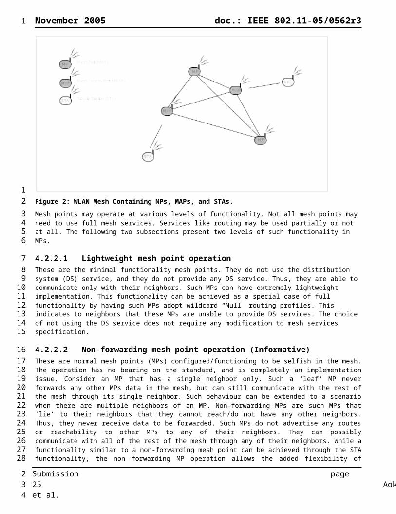
November 2005 doc.: IEEE 802.11-05/0562r3
Order Information Notes
4 Service Set Identifier (SSID)
When dot11WLANMeshService is true but the interface on which the beacon is being sent is not configured as an Access Point, the SSID IE shall be set to the wildcard value. [Note: the SSID is currently a required IE in beacon frames. To avoid having legacy STAs send association requests to non-MAP Mesh Points, a valid SSID should not be included in beacons sent by non-MAP Mesh Points. To avoid backward compatibility issues, rather than removing the SSID IE from MP (non-MAP) beacons the wildcard value is used.]
Add the following rows to the end of IEEE Std 802.11®-1999 Edition (Reaff 2003) Table 5 in Clause “7.2.3.1 Beacon frame format”
Table 2: Beacon frame body additions
Order Information Notes
T.B.D OFDM Parameter Set The OFDM Parameter Set information element is present within Beacon frames generated by STAs using Clause 17 PHYs.
T.B.D Mesh ID The Mesh ID information element shall be present within Beacon frames only when dot11WLANMeshService is true.
T.B.D WLAN Mesh Capability The WLAN Mesh Capability information element shall be present within Beacon frames only when dot11WLANMeshService is true.
T.B.D Neighbor List The Neighbor List information element shall be present within DTIM Beacon frames generated when dot11WLANMesh Service is true and MP is supporting Transmission to MP in power save.
T.B.D DTIM The DTIM IE shall be present in beacon frames generated by when dot11WLANMesh Service is true and MP is supporting Transmission to MP in power save.
T.B.D Mesh Portal Reachability
The Mesh Portal Reachability information element shall be present within Beacon frames only when dot11WLANMeshService is true.
T.B.D Beacon Timing The Beacon Timing information element shall be present within Beacon frames only when dot11WLANMeshService is true.
5.3.1.2 Association Request frame formatAdd the following rows to the end of IEEE Std 802.11®-1999 Edition (Reaff 2003) Table 7 in Clause “7.2.3.4 Associate Request frame format”:
Table 3: Association Request frame body additions
Order Information Notes
T.B.D Mesh ID The Mesh ID information element shall be present within
Submission page 25 Aoki, et al.
1
1
23
4
5
6
78
9
2
November 2005 doc.: IEEE 802.11-05/0562r3
Association Request frames only when dot11WLANMeshService is true.
T.B.D WLAN Mesh Capability The WLAN Mesh Capability information element shall be present within Beacon frames only when dot11WLANMeshService is true.
T.B.D Active Profile Announcement
The Active Profile Announcement information element shall be present within Beacon frames only when dot11WLANMeshService is true.
5.3.1.3 Reassociation Request frame formatAdd the following rows to the end of IEEE Std 802.11®-1999 Edition (Reaff 2003) Table 9 in Clause “7.2.3.6 Reassociation Request frame format”:
Table 4: Reassociation Request frame body additions
Order Information Notes
T.B.D Mesh ID The Mesh ID information element shall be present within Association Request frames only when dot11WLANMeshService is true.
T.B.D WLAN Mesh Capability
The WLAN Mesh Capability information element shall be present within Beacon frames only when dot11WLANMeshService is true.
T.B.D Active Profile Announcement
The Active Profile Announcement information element shall be present within Beacon frames only when dot11WLANMeshService is true.
5.3.1.4 Probe Request frame formatAdd the following rows to the end of IEEE Std 802.11®-1999 Edition (Reaff 2003) Table 11 in Clause “7.2.3.8 Probe Request frame format”:
Table 5: Probe Request frame body additions
Order Information Notes
T.B.D Mesh ID The Mesh ID information element shall be present within Beacon frames only when dot11WLANMeshService is true.
T.B.D WLAN Mesh Capability
The WLAN Mesh Capability information element shall be present within Beacon frames only when dot11WLANMeshService is true.
5.3.1.5 Probe Response frame formatAdd the following rows to the end of IEEE Std 802.11®-1999 Edition (Reaff 2003) Table 12 in Clause “7.2.3.9 Probe Response frame format”:
Table 6: Probe Response frame body additions
Submission page 26 Aoki, et al.
1
1
2
34
5
6
7
89
10
11
12
1314
15
2
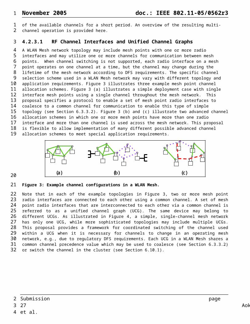
November 2005 doc.: IEEE 802.11-05/0562r3
Order Information Notes
T.B.D OFDM Parameter Set The OFDM Parameter Set information element is present within Beacon frames generated by STAs using Clause 17 PHYs.
T.B.D Mesh ID The Mesh ID information element shall be present within Beacon frames only when dot11WLANMeshService is true.
T.B.D WLAN Mesh Capability The WLAN Mesh Capability information element shall be present within Beacon frames only when dot11WLANMeshService is true.
T.B.D Mesh Portal Reachability The Mesh Portal Reachability information element shall be present within Beacon frames only when dot11WLANMeshService is true.
T.B.D DTIM The DTIM information element is only present in probes generated when dot11WLANMeshService is true and MP supports Power Save operation.
5.3.2 Management frame body components
5.3.2.1 Action fieldInsert the mesh management item in IEEE Std 802.11®-1999 (Reaff 2003) Table 21 as shown:
Table 7: Action frame category values
Name Value See subclause
Spectrum management 0 7.4.1
Reserved 1-3 -
Radio measurement 4 7.4.2
Mesh management 5 -
Reserved 6-127
Error 128-255 -
5.3.3 Information elements
5.3.3.1 WLAN Mesh Capability ElementA new “WLAN Mesh Capability” element is used to advertise WLAN Mesh services. It is contained in beacons transmitted by MPs, and is also contained in probe response messages.
MPs may support one or more path selection protocols and path metrics. However, only one path selection protocol and one path metric may be active in a particular WLAN mesh network at any point in time.
The WLAN Mesh Capability Element notifies an active path selection protocol, an active path metric, a supported protocol list and a supported path metric.
Octets: 1
1 1 4 4 2 1 1 4 4
Submission page 27 Aoki, et al.
1
1
2
3
4
5
6
7
8
910
1112
1314
2

November 2005 doc.: IEEE 802.11-05/0562r3
ID Length Version Active Protocol
ID
Active Metric
ID
Peer Capacity
Power Save
capability
Synchronization Capability
Channel Precedence
Multi-Channe
lCapabil
ity
Figure 12: WLAN Mesh Capability Element
The fields contained in the element are as shown in Table 8.
Table 8: WLAN Mesh Capability Element Fields
Field Value/description
ID T.B.D
Length Variable
Version 1
Active Protocol ID Path selection protocol in use
Active Metric ID Path selection metric in use
Peer capacity Peer capacity value
Power Save capability Support for power save operation and current power save status
Synchronization Capability Support for synchronization services and current synchronization status
Channel precedence Channel precedence value
Multi-Channel Capability CCF parameters and support for channel switching
The peer capacity value is treated as a single field, with the least significant octet transmitted first. It contains four sub-fields as shown in Figure 13.
15 14 13 12 0
Operating as MP
Operating in simple
unification mode
Connected to AS
Peer capacity
Figure 13: Peer Capacity Field
The “operating as MP” subfield is set to one if the device is currently operating as a MP, and zero otherwise. The “operating in simple unification mode (6.3.5.2)” subfield is set to one if the logical radio interface is currently operating in the simple unification mode, and zero otherwise. The “connected to AS” subfield specifies whether the mesh point is connected to an AS (Authentication Server), enabling the MP to support authentication and key management with IEEE802.1x. The “peer capacity” subfield is set to the number of additional MP peers that the device can accommodate.
The channel precedence field is set to the value of channel precedence of the unified channel graph to which the MP interface belongs.
Submission page 28 Aoki, et al.
1
1
2
3
4
56
7
8
910111213
1415
2

November 2005 doc.: IEEE 802.11-05/0562r3
The Power Save capability field includes 5 sub-fields
7 6 5 4-0Supporting Power Save
Requires Power Save Support
from Peer
Current Power Save State
Reserved
Figure 14: Power Save Capability field
The “Supporting Power Save” subfield indicates if the Mesh Point supports power save operation.The “Required Power Save Support from peer” subfield indicates if this mesh point requires peers attempting to associate or directly communicate with it to support Power Save operation.The Current Power Save State” sub filed indicates the current Power Save state of the mesh point. A set bit indicates the mesh point is operating in Power Save mode. A cleared bit indicates it is in active state.
The Synchronization Capability field includes 3 sub-fields
Bits: 0 1 2 3-7
Supporting Synchronization
Requests Synchronization from Peer
Synchronizing with peer MP
Reserved
Figure 15: Synchronization Capability Field
The “Supporting Synchronization” subfield is set to 1 if the Mesh Point supports timing synchronization with peer MPs, and 0 otherwise.
The “Requests Synchronization from Peer” subfield is set to 1 if the mesh point requests MP peers attempting to communicate with it to synchronize with it, and 0 otherwise.
The “Synchronizing with Peer MP” subfield is set to 1 if the non-AP MP is currently a synchronizing MP, and 0 otherwise.
The multi-channel capability field includes 4 sub-fields, shown in Figure 16.
31 30 29-24 23-16 15-0Channel Switching
CapabilityReserved CCW P
Figure 16: Multi-Channel Capability field
The “Channel Switching Capability” subfield indicates if an MP can perform channel switching within TBD s for the multi-channel operation.The “CCW” subfield indicates the duration of channel coordination window as a fraction of P.The “P” subfield indicates the period with which CCW repeats. This is expressed in 28 s units.The “” subfield indicates an offset, with respect to P, at which the beacon is transmitted. The offset is expressed in units of 1s.
5.3.3.1.1 Protocol identifierProtocol identifier is contained in Active Protocol field and Supported Protocol List. This information identifies the path selection protocol for unicast, multicast and broadcast transmission. Protocol profile has format shown in Figure 17.
Octets: 3 1
OUI Protocol Identifier
Submission page 29 Aoki, et al.
1
1234
5
6789
1011121314
15
161718192021222324252627
28
293031323334
35
3637
2
November 2005 doc.: IEEE 802.11-05/0562r3
Figure 17: Protocol identifier format
The protocol identifier specifies the protocol which is currently used to generate routing information in this network, as defined in Section 6.4.
Table 9: Protocol Identifier Values
OUI Value Meaning
00-0F-AC 0 Hybrid Wireless Mesh Protocol (default path selection protocol)
00-0F-AC 1 Radio Aware OLSR (optional path selection protocol)
00-0F-AC 2-254 Reserved for future use
00-0F-AC 255 Null protocol
Vendor OUI Other Vender specific
A Null protocol indicates the MP has no active layer 2 path selection and forwarding. An MP with Null protocol will not send or respond to path selection protocol messages.
5.3.3.1.2 Metric IdentifierMetric identifier is contained in Active Metric field. This information identifies the path metric which is currently used by the active path selection protocol in the WLAN mesh network. Metric identifier has format shown in Figure 18.
Octets: 3 1
OUI Metric Identifier
Figure 18: Metric identifier format
The protocol identifier specifies the protocol that is used to generate routing information in this network, as defined in Table 10.
Table 10: Metric Identifier Values
OUI Value Meaning
00-0F-AC 0 Airtime path metric (default path metric)
00-0F-AC 1-254 Reserved for future use
00-0F-AC 255 Null metric
Vendor OUI Other Vender specific
Null metric is used in conjunction with Null protocol setting.
Submission page 30 Aoki, et al.
1
1
23
4
567
8
910
11
12
1314
15
16
17
2
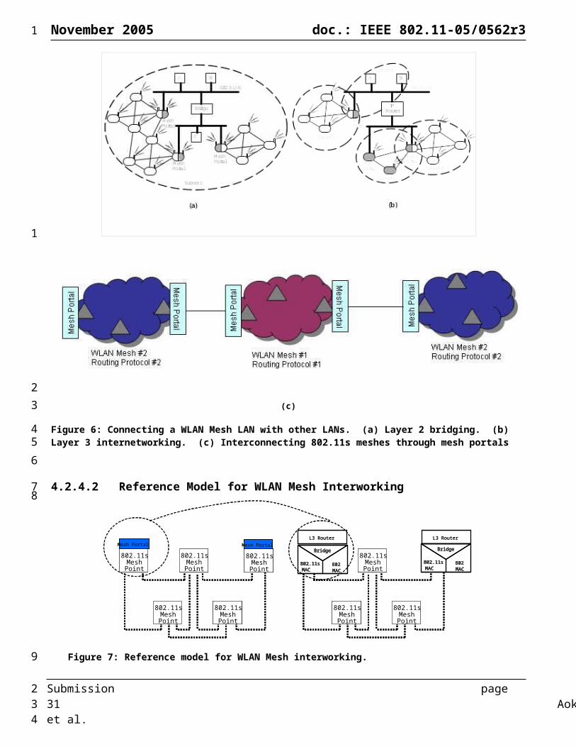
November 2005 doc.: IEEE 802.11-05/0562r3
5.3.3.2 Active Profile Announcement ElementA new “Active Profile Announcement” element is used to notify the profile pair of the active path selection protocol and the active path metric to a peer MP. It is contained in association request message transmitted by the association requesting MP. The profile pair is selected by the association requesting MPs local mechanism.
Octets: 1 1 1 1 1
ID Length Version Active Protocol
ID
Active Metric
ID
Figure 19: Active Profile Announcement Element
The fields contained in the element are as shown in Table 11.
Table 11: Active Profile Announcement Element Values
Field Value/description
ID T.B.D
Length Variable
Version 1
Active Protocol ID Path Selection Protocol in use
Active Metric ID Path Selection Metric in use
5.3.3.3 Mesh ID Element“Mesh ID” element is used to advertise the identification of WLAN mesh network. A 0 length information field may be used within Probe Request management frame to indicate the wildcard Mesh ID.
Octets: 1 1 0-32
Element ID Length Mesh ID
Figure 20: Mesh ID element format
5.3.3.4 Local Link state announcement ElementA local link state announcement message is transmitted by an MP to a neighbor MP to indicate the status of the link between them. The purpose of this message is to ensure that the link quality is symmetric for all Mesh links.
Octets: 1 1 2 2
ID Length r ept
Figure 21: WLAN Mesh Local Link State Announcement Element
Submission page 31 Aoki, et al.
1
1
234
5
6
7
8
9
10
1112
13
14
15
16
1718
19
2
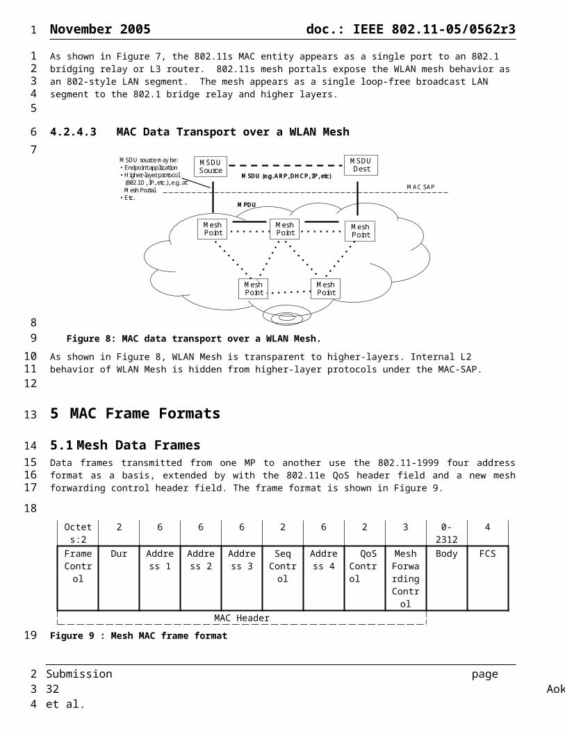
November 2005 doc.: IEEE 802.11-05/0562r3
The fields contained in the element are as shown in Table 12.
Table 12: WLAN Mesh Local Link State Announcement Element Fields
Field Value/description
ID TBD
Length 8
r Transmit bit rate
ept PER
The rate field, r, shall be interpreted as a 16-bit unsigned integer, with the least significant octet transmitted first, which indicates the on-air bit rate currently in use in units of 1Mb/s.
The PER, ept, shall be interpreted as a 16-bit unsigned binary fraction, with the least significant octet transmitted first, such that a value of 0xffff corresponds to a fractional value of:
and which indicates an estimated packet error rate for a data frame containing a payload of 1000 bytes transmitted at the bit rate specified in the r field.
5.3.3.5 HWMP Information Elements
5.3.3.5.1 Route Request Element
Octets: 1 1 1 1 1 4 6 4
ID Length Mode Flags
Dest Count
Hop Count
RREQ ID
Source Address
Source Seq. Num.
4 6 4 6 4
Metric Destination Address #1
Destination Seq. Num.#1
…. Destination Address #N
Destination Seq. Num.#N
Figure 22: Route Request Element
Table 13: Route Request Element Fields
Field Value/description
ID TBD
Length
Mode Flags Bit 0: Request mode (0 = Topology; 1 = On-demand)
Bit 1: Broadcast mode (0 = Topology; 1 = Discovery)
Bit 2 – 7: Reserved
Submission page 32 Aoki, et al.
1
1
2
34
56
7
89
10
11
12
13
14
15
2

November 2005 doc.: IEEE 802.11-05/0562r3
Field Value/description
Dest. Count The number of <destination, dest. sequence number> pairs in the message
Hop Count The number of hops from the Source MAC Address to the node handling the request
RREQ ID A sequence number uniquely identifying the particular RREQ when taken in conjunction with the originating MP's MAC address
Source Address The MAC address of the source MP
Source Sequence Number The current sequence number to be used in the route entry pointing towards the source of the route request.
Metric The cumulative metric from the Source to the node handling the request
Destination Address The MAC address of the destination for which a route is desired (All zero in case of Mode Flags bit 1 = 1).
Destination Sequence Number
The latest sequence number received in the past by the source for any route towards the Destination MP. A value of 0 indicates that the source does not know the sequence number of the destination.
5.3.3.5.2 Route Reply Element
Octets: 1 1 1 1 6 4
ID Length Mode Flags
Src Count Destination Address
Destination Seq.Num.
4 4 6 4 6 4
Lifetime Metric Source Address
#1
Source Seq.
Num. #1
... Source Address
#N
Source Seq.
Num. #N
Figure 23: Route Reply Element
Table 14: Route Reply Element Fields
Field Value/description
ID TBD
Length
Flags Bit 0: Request mode (0 = On-demand; 1 = Gratuitous)
Bit 1: Transfer mode (0 = Intra-mesh; 1 = Portal-Portal)
Bit 2 – 7: Reserved
Src Count The number of <source, src. Sequence number> pairs in the message
Submission page 33 Aoki, et al.
1
1
2
3
4
5
67
2
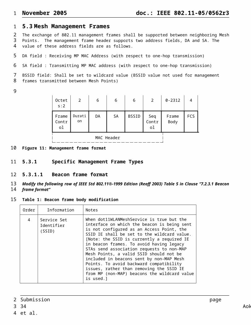
November 2005 doc.: IEEE 802.11-05/0562r3
Field Value/description
Destination Address The MAC address of the destination for which a route is desired.
Destination Sequence Number
The latest sequence number received in the past by the source for any route towards the Destination. A value of 0 indicates that the source does not know the sequence number of the destination.
Life Time The time in milliseconds for which nodes receiving the RREP consider the route to be valid
Metric The cumulative metric from the Destination MAC address to the node handling the RREP
Source Address The MAC address of the node which originated the RREQ for which the route is supplied.
Source Sequence Number The current sequence number to be used in the route entry pointing towards the source of the route request.
5.3.3.5.3 Route Error Element
Octets: 1 1 1 1 (or 4) 6 4
ID Length Mode Flags Num of destination
Destination Address
Destination MP Seq. Num
Figure 24: Route Error Element
Table 15: Route Error Element Fields
Field Value/description
ID TBD
Length
Mode Flags Bit 0: Operating mode (0 = Delete; 1 = Repair)
Bit 1: Transfer mode (0 = Intra-mesh; 1 = Portal-Portal)
Bit 2: Error mode (0 = On-demand only; 1 = All)
Bit 3 – 7: Reserved
Destination Address Detected unreachable destination MAC address
Destination Sequence Number
The sequence number of detected unreachable destination MP
5.3.3.5.4 Route Reply Ack Element
Octets: 1 1 6 4 6 4
Submission page 34 Aoki, et al.
1
1
2
3
4
56
7
8
9
2

November 2005 doc.: IEEE 802.11-05/0562r3
ID Length Destination Address
Destination MP Seq. Num
Source Address
Source MP Seq. Num
Figure 25: Route Reply Ack Element
Table 16: Route Reply Ack Element Fields
Field Value/description
ID TBD
Length 12
Destination Address The MAC address of the destination for which a route is desired.
Source Address The MAC address of the node which originated the RREQ for which the route is supplied
5.3.3.6 OFDM Parameter ElementA new “OFDM Parameter” element is used to advertise current channel identification to the neighbor MP with OFDM PHY. It is contained in beacons transmitted by MPs, and is also contained in probe response messages.
The OFDM Parameter Set element contains information to allow channel number identification for MPs using an OFDM PHY. The information field contains a single parameter containing the dot11CurrentChannelNumber (see 15.4.6.2 for values). The length of the dot11CurrentChannelNumber parameter is 1 octet. See Figure 26.
Octets: 1 1 1
ID Length Current Channel
Figure 26: OFDM Parameter Set Element Format
5.3.3.7 Target Transmission Rate ElementA new “Target Transmission Rate” element is used in the Flow Control Request frame by a Mesh Point to indicate to its upstream neighbor the target data rate the two Mesh Points should coordinate to maintain. It contains four target Data Rate fields for the four 802.11e EDCA access categories and an Expiration Timer. The total length of this information is 20 octets.
Octets: 1 1 4 4 4 4 2
ID Length Target Data Rate (AC_BK)
Target Data Rate (AC_BE)
Target Data Rate (AC_VI)
Target Data Rate (AC_VO)
Expiration Timer
Submission page 35 Aoki, et al.
1
1
23
4
5
6
78
91011
12
13
14
15
16
171819
20
2

November 2005 doc.: IEEE 802.11-05/0562r3
Figure 27: Target Transmission Rate Element Format
Target Data Rate for a given Access Category indicates the mean transmission rate in bits/s from the upstream Mesh Point to the downstream neighboring Mesh Point for this AC. The upstream Mesh Point must not exceed the target Data Rate; otherwise it may result in congestion at the downstream node.
Expiration timer indicates the valid period of Target Data Rates information provided in this element. Expiration Timer is represented in TU.
5.3.3.8 Offered Traffic Load ElementA new “Offered Traffic Load” element is used in the Flow Control Response frame by a Mesh Point to indicate to its downstream neighbor the incoming traffic load between itself and the downstream neighbor. It contains four Offered Traffic Load fields for the four access categories. The total length of this information is 18 octets.
Octets: 1 1 4 4 4 4
ID Length Offered Traffic Load
(AC_BK)
Offered Traffic Load
(AC_BE)
Offered Traffic Load
(AC_VI)
Offered Traffic Load
(AC_VO)
Figure 28: Offered Traffic Load Element Format
Offered Traffic Load for a given Access Category indicates the incoming traffic rate in bits/s estimated or measured at the MAC interface. This information can be used by the downstream neighboring Mesh Point to better estimate the Target Data Rate.
5.3.3.9 Neighborhood Congestion ElementA new “Neighborhood Congestion” element is used by a Mesh Point to indicate to its neighbors its congestion level. It contains a congestion level field and an expiration timer field. The total length of this information is 5 octets.
Octets: 1 1 1 2
ID Length Congestion Level
Expiration Timer
Figure 29: Neighborhood Congestion Element Format
The congestion level is TBD.
Expiration timer indicates the valid period of congestion information provided in this element. Expiration Timer is represented in TU.
5.3.3.10 MP Peer Request ElementThe MP peer request element is transmitted by an MP to a neighbor in order to request creation of a peer relationship.
Octets: 1 1 2
Submission page 36 Aoki, et al.
1
1
234
56
7
8
91011
12
13
141516
17
1819
20
21
22
2324
25
26
2728
2

November 2005 doc.: IEEE 802.11-05/0562r3
ID Length Directionality
Figure 30: WLAN Mesh Peer Request Element
The fields contained in the element are as shown in Table 17.
Table 17: WLAN Mesh Peer Request Element Fields
Field Value/descriptionID TBD
LengthDirectionality Random directionality value
The directionality field contains a random number chosen by the source in order to prevent two MPs from establishing peering requests for each other simultaneously.
5.3.3.11 MP Peer Response ElementThe MP peer response element is transmitted by an MP to a neighbor in response to an MP peer request.
Octets: 1 1 1
ID Length Status
Figure 31: MP Peer Response Element
The fields contained in the element are as shown in Table 18.
Table 18: MP Peer Response Element Fields
Field Value/descriptionID 221
LengthStatus Status code
The status code has a value indicating whether the request was accepted or denied, according to the values and meanings contained in Table 19.
Table 19: MP Peer Response Status Codes
Value Meaning0 Request accepted1 Request denied
2-255 Reserved
5.3.3.12 Mesh Portal Reachability Element“Mesh Portal Reachability“ element is used to advertise the identification of one or more Mesh Portal to which an MP is able to communicate. This information element is included in Beacon and Probe response frame.
Octets: 1 1 1 10*n
Element ID Length Number of Mesh Portals
Mesh Portal Description
Figure 32: Mesh Portal Reachability element format
Submission page 37 Aoki, et al.
1
1
2
3
45
67
8
9
10
1112
13
14
15
1617
18
19
2
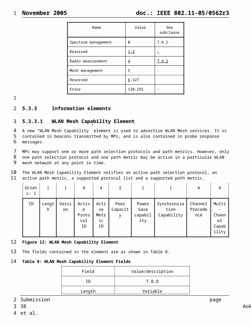
November 2005 doc.: IEEE 802.11-05/0562r3
Octets: 6 4
Mesh Portal MAC address
Metric
Figure 33: Mesh Portal Description format
Table 20: Mesh Portal Reachability element fields
Field Value/description
ID TBD
Length Value
Number of Mesh Portals The number of connected Mesh portals
Mesh Portal Description The list of Mesh Portal descriptions for Mesh Portals that are reachable from the MP. This field has a description entry for each reachable Mesh Portal consisting of the Mesh Portal MAC address and the path metric from the MP to the Mesh Portal.
5.3.3.13 Mesh Portal/Root Announcement ElementMesh Portals periodically broadcast Portal announcement to the WLAN Mesh network every PORTAL_ANNOUNCEMENT_TIME interval. The Portal announcement messages serve three purposes to the mesh network:
1) Announcing the Mesh Portal to the WLAN Mesh nodes allows the MPs to designate the Mesh Portal as a packet forwarder after receiving the annoucement message if they wish to.
2) Announcing the Mesh Portal to other Portals helps all Portals discover the uplinks present in the network and ensures that frames with unknown addresses are forwarded on all uplinks from the mesh network.
3) Allows unconfigured Root Portals to arbritrate and choose a single Portal as Root for hybrid wireless mesh protocol (HWMP) topology building when topology building is enabled via a management entity.
The Root announcement with HWMP-Registration flag set allows the HWMP topology to form. When this flag is not set, the announcements propagate in the network as per Section 6.4.3 Path Selection Protocol.
Octets: 1 1 1 6 1 1 6
Element ID Length Flags Mesh Portal Bridge ID
Priority Number of Mesh
Portals
Mesh Portal Address
4 4 4 1 6*n
Root Seq. Num
Lifetime Root Metric Topology Maintenance
Connected Mesh Portal
Submission page 38 Aoki, et al.
1
1
2
34
5
67
89
10111213141516171819202122232425
26
2
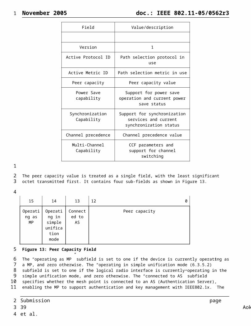
November 2005 doc.: IEEE 802.11-05/0562r3
Policy IDs
Figure 34: Mesh Portal/Root Advertisement Element
Table 21: Mesh Portal/Root Advertisement Element Fields
Field Value/description
ID TBD
Length Length of the IE
Flags Bit 0: Announcement type (0 = Portal; 1 = Root)
Bit 1: HWMP Registration (0 = Disabled; 1 = Enabled)
If the flag is set, registration of MPs with the root portal occurs, otherwise it does not.
Bit 2 – 7: Reserved
Mesh Portal Bridge ID Mesh Portal’s unique bridge ID (802.1D configuration BPDUs contain bridge ID)
Priority A Mesh Portal has the lowest priority value becomes the default Mesh Portal. (0~255). A value of 0 means it is configured as a Root.
Number of Mesh Portal The number of the connected Mesh Portals which have wired and wireless connectivity.
Mesh Portal Address Mesh Portal MAC address
Root Sequence Number The latest sequence number received in the past by the source for any route towards the Root.
Life Time The time in milliseconds for which nodes receiving the RREP consider the route to be valid.
Metric The cumulative metric from the Root to the node advertising the announcement.
Topology Maintenance Policy 0: Policy 1 (Suboptimal)
1: Policy 2
2: Policy 3
3: Policy 4 (Optimal)
Connected Mesh Portal IDs The list of Mesh Portal MAC addresses which have both wired and wireless connectivity. A value of 0 indicates it is a Root announcement and not a Portal announcement.
Submission page 39 Aoki, et al.
1
12
3
4
5
6
7
8
2

November 2005 doc.: IEEE 802.11-05/0562r3
5.3.3.14 Channel Cluster Switch Announcement elementThe Channel Cluster Switch Announcement element is used by an MP in a WLAN Mesh to advertise when it is changing to a new channel and the channel number and precedence value of the new channel (See Section 6.10.1). The format of the Channel Cluster Switch Announcement element is shown in Figure 35.
The MP peer response element is transmitted by an MP to a neighbor in response to an MP peer request.
Octets: 1 1 1 1 4 1 6
ID Length Channel Switch Mode
New Channel Number
New Channel
Precedence Indicator
Channel Switch Count
Source Address
Figure 35: Channel Cluster Switch Announcement Element
The Length field shall be set to 13.
The Channel Switch Mode field indicates any restrictions on transmission until a channel switch. an MP shall set the Channel Switch Mode field to either 0 or 1 on transmission. A Channel Switch Mode set to 1 means that the MP to which the frame containing the element is addressed is advised to transmit no further frames on the current channel until the scheduled channel switch. A Channel Switch Mode set to 0 does not impose any requirement on the receiving STA.
The New Channel Number field shall be set to the number of the channel to which the MP is moving.
The New Channel Precedence Indicator field shall be set to the channel precedence value of the channel to which the MP is moving.
The Channel Switch Count field either shall be set to the number of time units (TUs) until the MP sending the Channel Cluster Switch Announcement element switches to the new channel or shall be set to 0. A value of 0 indicates that the switch will occur at any time after the frame containing the element is transmitted.
The Source Address field shall be set to the address of the Mesh Point that originates the frame.
The Channel Cluster Switch Announcement element is included in Channel Cluster Switch Announcement frames.
5.3.3.15 Neighbor List elementThe Neighbor List element is used by an MP to advertise its neighbor list and their Power Save states. The element contains list of current neighbor MAC addresses and information about the neighbor power save state.
The format of the Neighbor List element is shown in Figure 36
Octets: 1 1 1 6 6 ... 6 k
ID Length MP control MAC Address of terminal 1
MAC Address of terminal 2
... MAC Address of terminal n
PS states
Figure 36: Neighbor List element
The MAC Address fields indicate the MAC address of the current neighbor list of the MP.
The format of the MP control field is shown in Figure 37
Bits: 0-45 5 6 7
Reserved Designated BB switch BB PS
Submission page 40 Aoki, et al.
1
1234
5
6
7
89
1011
12
1314
151617
18
19
20
21
222324252627
28
29303132
2
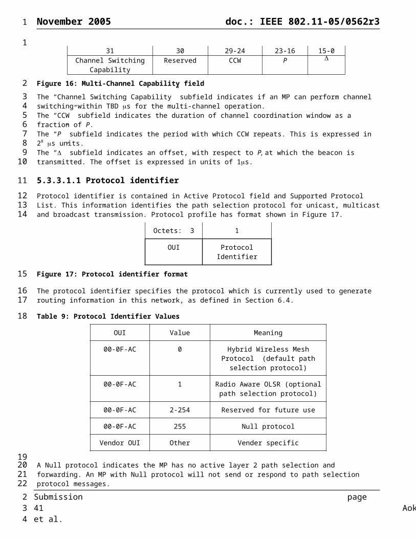
November 2005 doc.: IEEE 802.11-05/0562r3
BB state
Figure 37: MP Control field
The Designated BB field is used to indicate that the current beacon broadcaster is a designated beacon broadcaster that operates according to the scheme described in section 6.12.8.
The BB switch field is used to indicate the change of the beacon broadcaster. If the bit in the DTIM frame is set to 1, the next beacon shall be sent by the MP whose MAC address is the first one in the neighbor list.
The BB PS state field indicates whether the beacon broadcaster is using power save mode. If BB PS state bit is set to 1, then beacon broadcaster sends only DTIM frames. If BB PS state bit is set to 0, then beacon broadcaster is awake all the time.
The PS states field indicates the current power save state of each neighbor list member. Each bit of this field indicates the power save state of the corresponding neighbor list member. If a bit is set to 0, then the corresponding neighbor list member is in awake state and if a bit is set to 1, the corresponding neighbor list member is in power save state. For example, if the neighbor List element contains 8 MAC addresses and PS states is ‘00110001’, then the MPs with MAC addresses in positions 3, 4, and 8 in the neighbor list are in the power save state. PS state field length is always an integer number of octets.
5.3.3.16 DTIM elementThe DTIM element is used by an MP acting as a beacon broadcaster. The element contains information about the DTIM period of the Mesh.
The format of the DTIM element is shown in Figure 36
Octets: 1 1 1 1
ID Length DTIM Count
DTIM Period
Figure 38: DTIM element
The DTIM Count field indicates how many beacons (including the current frame) appear before the next DTIM. A DTIM count of 0 indicates that the current TIM is a DTIM. The DTIM count field is a single octet.
The DTIM Period field indicates the number of Beacon intervals between successive DTIMs. If all TIMs are DTIMs, the DTIM Period has the value 1. The DTIM Period value 0 is reserved. The DTIM period field is a single octet.
MAP will include both a TIM and a DTIM element. The DTIM Period of these IEs do not have to be identical since one will be used for the AP service while the other will be used for the Mesh service.
5.3.3.17 Beacon Timing element
The Beacon Timing element is used by a synchronizing MP to advertise an offset between its self TSF and the Mesh TSF, and to advertise the beacon timing information of zero or more of its neighbors.
The format of the Beacon Timing element is shown in Figure 39.
Octets: 1
1 4 1 1 3 1 3 ...
ID Length Self Beacon Timing
Number of
Synchronizing neighbors
Last byte of MAC Address
Synchronized
Beacon Timing
Last byte of MAC Address
Synchronized
Beacon Timing
...
Submission page 41 Aoki, et al.
1
1
23456789
1011121314151617
181920212223
24
252627282930313233
3435363738394041
2
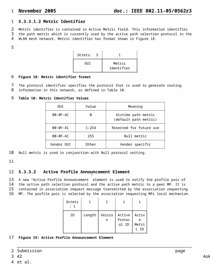
November 2005 doc.: IEEE 802.11-05/0562r3
reported of Synch Terminal 1
terminal 1 of Synch Terminal 2
terminal 2
1 3 1 5 … 1 5
Last byte of MAC Address of Synch Terminal n
Synch
Beacon Timing
terminal n
Last byte of MAC Address of Unsynch Terminal 1
Unsynchronized Beacon Timing unsynch terminal 1
… Last byte of MAC Address
of Unsynch Terminal
m
Unsynchronized Beacon Timing
unsynch terminal m
Figure 39: Beacon Timing element
The format of the Self Beacon Timing field is shown in Figure 40.
Bits: 0-23 24-31
Self TBTT offset
MP DTIM period
Figure 40: Self Beacon timing
The ‘Self TBTT offset’ subfield of the Self Beacon timing field indicates the offset, measured in microseconds, used by the MP for its TSF time compared to the Mesh TSF. The sum of the MP TSF time stamp and the offset equals the mesh TSF time.
The ‘MP DTIM period’ subfield of the Self Beacon timing field indicates the MP DTIM period of the specific MP (i.e. how many Beacon intervals of the MP compose a single Mesh DTIM interval).
The ‘Number of Synchronizing Neighbors Reported’ field specifies the number of synchronizing neighbors whose beacon timing information is reported following this field.
The beacon timing information of synchronizing neighbors is reported in terms of the last byte of MAC address field and the ‘Synchronized Beacon Timing’ field which are included as pairs. The Beacon Timing element may contain zero or more ‘Last byte of MAC Address of Synch Terminal’ and the ‘Synchronized Beacon Timing’ field pairs.
The Last Byte of MAC Address of Synch Terminal field indicates the last byte of the MAC address of neighbors that have a non-zero Self TBTT offset value, whose information is reported in the value of the next ‘Synchronized Beacon Timing’ field.
The format of the Synchronized Beacon Timing field is shown in Figure 41.
Bits: 0-7 8-15 16-23
TBTT offset
Time since last beacon
MP DTIM period
Figure 41: Synchronized Beacon Timing field
Submission page 42 Aoki, et al.
1
1
2
3
4
56
7
89
101112131415161718192021222324252627
28
29
2
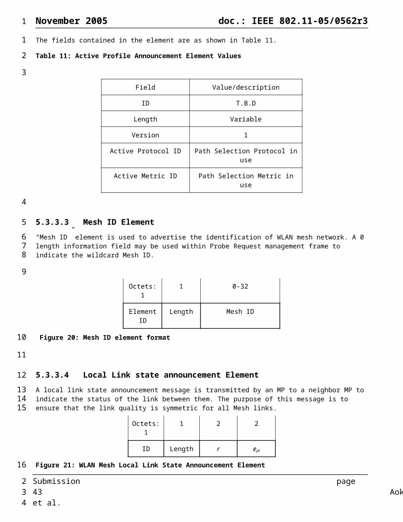
November 2005 doc.: IEEE 802.11-05/0562r3
The ‘TBTT offset’ field is expressed in units of TU, and indicates the offset used by the neighboring MPs for their TSF time stamps compared to the Mesh TSF. For those MPs reporting self TBTT offsets with a higher resolution than a TU, the field is rounded to the nearest TU.
The ‘Time since last beacon’ field indicates the time passed measured in units of Mesh DTIM intervals since last beacon was received from the specific MP.
The ‘MP DTIM period’ field indicates the MP DTIM period of the specific MP (i.e. how many Beacon intervals of the MP compose a single Mesh DTIM interval).
Beacon timing information for unsynchronizing MP neighbors may also be included at the end of the Beacon timing element following the synchronizing neighbor information.
The beacon timing information of unsynchronizing neighbors is reported in terms of the ‘Last byte of the MAC Address of Unsynch Terminal’ and the ‘Unsynchronized Beacon Timing’ fields which are included as pairs. The Beacon Timing element may contain zero or more ‘Last byte of MAC Address of Unsynch Terminal’ and ‘Unsynchronized Beacon Timing’ field pairs.
The ‘Last byte of the MAC Address of Unsynch Terminal’ indicates the last byte of the MAC address of unsynchronizing neighbor whose beacon timing information is reported in the value of the next ‘Unsynchronized Beacon Timing’ field.
The format of the ‘Unsynchronized Beacon Timing’ field is as shown in Figure 42.
Bits: 0-23 24-39
Last Beacon Time
MP Beacon Interval
Figure 42: Unsynchronized Beacon Timing field
The Last Beacon Time field is measured in microseconds and specifies the time at which the last beacon from the specified MP was received relative to the beacon time stamp of the IE transmitting MP, or the most recent TBTT of the IE transmitting MP if the Beacon Timing element is encapsulated in a response frame.
The MP Beacon Interval field specifies the beacon interval being used by the MP whose information is being reported.
5.3.4 Action frame format details
5.3.4.1 Mesh management action detailsAction frame formats are defined for mesh management. An Action field, in the octet field immediately after the Category field, differentiates the frame format. The Action field values associated with each frame format are defined in Table 22.
Table 22: Mesh management Action field values
Action field value
Description Application
0 Local Link state announcement Neighbor discovery
1 Peer Link Disconnect Neighbor discovery
Submission page 43 Aoki, et al.
1
123456789
101112131415161718192021222324
25
26
27282930
32333435
36
37
3839
40
2
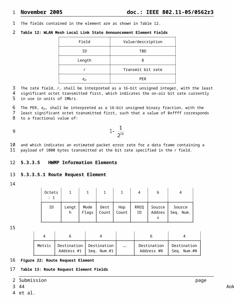
November 2005 doc.: IEEE 802.11-05/0562r3
2 Route Request HWMP routing
3 Route Reply HWMP routing
4 Route Error HWMP routing
5 Route Reply Ack HWMP routing
6 Congestion Control Request Congestion Control
7 Congestion Control Response Congestion Control
8 Neighborhood Congestion Announcement Congestion Control
9 Reserved
10 Reserved
11 Legacy Action Encapsulation Action
16-254 Reserved
255 Vender Specific Mesh Management Vender Specific
5.3.4.2 Local Link State Announcement frame formatThe Local Link State Announcement frame format uses the Action frame body format and is transmitted by an MP to a neighbor MP in WLAN mesh to advertise metric information. This frame is typically transmitted in a broadcast manner. The frame format is shown in Figure 43.
Octets: 1 1 Variable
Category Action Local Link State Announcement Element
Figure 43: Local Link State Announcement frame format
The Category field shall be set to 5 (representing mesh management).The Action field shall be set to 0 (representing Local Link state announcement)The Local Link State Announcement element field shall be set as described in Section 5.3.3.4.
5.3.4.3 Route Request frame formatThe Route Request frame format uses the Action frame body format and is transmitted by a source MP to discover the path to the destination MP. This frame is typically transmitted in a broadcast manner. The intermediate MP rebroadcasts this frame. The frame format is shown in Figure 51.
Octets: 1 1 Variable
Category Action Route Request Element
Figure 44: Route Request frame format
The Category field shall be set to 5 (representing mesh management).
Submission page 44 Aoki, et al.
1
1
2
34567
8
910111213
1415161718
19
2021
2

November 2005 doc.: IEEE 802.11-05/0562r3
The Action field shall be set to 1 (representing Route Request)The Route Request elements field shall be set as described in Section x.
5.3.4.4 Route Reply frame formatThe Route Reply frame format uses the Action frame body format and is transmitted by a destination MP to source MP in WLAN mesh to determine the path between the source and destination MP. This frame is typically transmitted in a unicast manner. The frame format is shown in Figure 45.
Octets: 1 1 Variable
Category Action Route Reply Element
Figure 45: Route Replay frame format
The Category field shall be set to 5 (representing mesh management).The Action field shall be set to 2 (representing Route Request)The Route Reply elements field shall be set as described in Section x.
5.3.4.5 Route Error frame formatThe Route Request frame format uses the Action frame body format and is transmitted by the MP detected the link failure on a certain path to the precursor MP. This frame is typically transmitted in a unicast manner. The frame format is shown in Figure 46.
Octets: 1 1 Variable
Category Action Route Error Element
Figure 46: Route Error frame format
The Category field shall be set to 5 (representing mesh management).The Action field shall be set to 3 (representing Route Error)The Route Error elements field shall be set as described in Section x.
5.3.4.6 Route Reply Ack frame formatThe Route Reply Ack frame format uses the Action frame body format and is transmitted by a source MP to a destination MP in response to a Route Reply frame. This frame is typically transmitted in a unicast manner. The frame format is shown in Figure 47.
Octets: 1 1 Variable
Category Action Route Reply Ack Element
Figure 47: Route Request frame format
The Category field shall be set to 5 (representing mesh management).The Action field shall be set to 4 (representing Route Reply Ack)The Route Reply Ack elements field shall be set as described in Section 5.3.3.5.4.
Submission page 45 Aoki, et al.
1
12
34567
8
910111213
1415161718
19
2021222324
2526272829
30
313233343536
2

November 2005 doc.: IEEE 802.11-05/0562r3
5.3.4.7 Congestion Control Request frame formatThe Congestion Control Request frame format uses the Action frame body format and is sent by an MP to its upstream neighboring MP to indicate the target data rate it desires, or the peak data rate it wants its neighbor not to exceed so as to avoid or control congestion. This frame can also be used to indicate to its neighbors about the current traffic load in case of congestion. This frame is transmitted in a unicast manner. The frame format is shown in Figure 48.
Octets: 1 1 20
Category Action Target Transmission Rate
Element
Figure 48: Congestion Control Request frame format
The Category field shall be set to 5 (representing mesh management).The Action field shall be set to 6 (representing Congestion Control Request)The Target Transmission Rate element field shall be set as described in Section XX.
5.3.4.8 Congestion Control Response frame formatThe Congestion Control Response frame format uses the Action frame body format and is sent by an MP as a response to the “Congestion Control Request” from its downstream MP. This frame is transmitted in a unicast manner. The frame format is shown in Figure 49.
Octets: 1 1 18
Category Action Offered Traffic Load
Element
Figure 49: Congestion Control Response frame format
The Category field shall be set to 5 (representing mesh management).The Action field shall be set to 6 (representing Congestion Control Response)The Offered Traffic Load element field shall be set as described in Section 5.3.3.8.
5.3.4.9 Neighborhood Congestion Announcement frame formatThe Neighborhood Congestion Announcement frame format uses the Action frame body format and is sent by an MP that is congested due to the high channel load in the neighborhood. This frame is transmitted in a broadcast manner. The frame format is shown in Figure 50.
Octets: 1 1 5
Category Action Neighborhood Congestion
Element
Figure 50: Neighbor Congestion Announcement frame format
The Category field shall be set to 5 (representing mesh management).The Action field shall be set to 7 (representing Neighborhood Congestion Announcement)The Neighborhood Congestion Announcement element field shall be set as described in Section 5.3.3.9
5.3.4.10 Legacy Action Encapsulation frame formatNumerous information elements for action frames are already defined in IEEE 802.11, prior to the completion of 802.11s. Some of these frames (for example, DFS, TPC, measurement) are also applicable in multi-hop mesh network topologies..
Submission page 46 Aoki, et al.
1
123456
7
89
1011
12131415
16
17181920
21222324
25
2627282930
313233
2
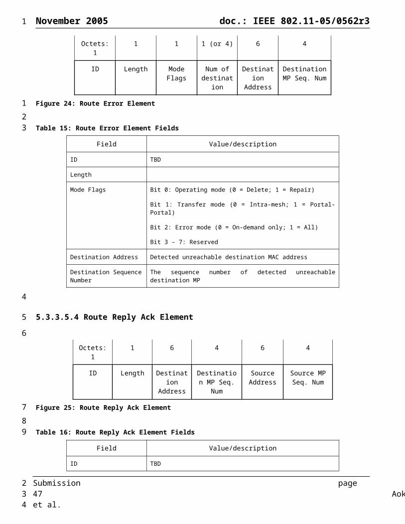
November 2005 doc.: IEEE 802.11-05/0562r3
However, the legacy action frame structure for carrying these information elements is designed mainly for 1-hop STA-AP transmission. The new “Legacy Action Encapsulation“ frame format is designed to transfer these legacy information elements through multi-hop WLAN mesh network topologies and gives a framework to encapsulate them. The Legacy Action Encapsulation frame uses the Action frame body format and is transmitted by a source MP requesting a destination MP for Route Reply information. The frame format is shown in Figure 51.
Octets: 1 1 6 6 Variable
Category Action Source MP Address
Destination MP Address
Encapsulated Action Frame
Figure 51: Legacy Action Encapsulation frame format
The Category field shall be set to 5 (representing mesh management).The Action field shall be set to 10 (representing legacy action escalation)The Source MP Address shall be set to the value of Source MP MAC address.The Destination MP Address shall be set to the value of Destination MP MAC address.The Encapsulated Action Frame Original shall contain the original action frame. The format of this field obeys the original frame format defined in the IEEE802.11 standard. This original format generally consists of three types of field (Category, Action and Element(s)) or four types of field (Category, Action, Dialog Token and Element(s)). Example of Legacy Action Encapsulation frame to carry Measurement Request action frame is shown in Table 23.
Table 23: Example of Legacy Action Encapsulation frame(Measurement Request)
Field Value/description
Category 5 (mesh management)
Action 10 (legacy action encapsulation)
Source MP Address Source MP MAC address
Destination MP Address Destination MP MAC address.
Encapsulated Action Frame
Category 0 (spectrum management)
Action 0 (Measurement Request)
Dialog Token 1
Element(s) Measurement Request Elements
5.3.4.11 Vender Specific Mesh Management frame formatThe Vender Specific Mesh Management frame format uses the Action frame body format and is used to carry information not defined in this standard within a single defined frame format, so that reserved Action IDs are not usurped for non-standard purposes and so that interoperability is more easily achieved in the presence of non-standard management frames. The frame format is shown in Figure 52.
Octets: 1 1 3 Variable
Category Action OUI Vendor specific content
Figure 52: Vender Specific Mesh Management frame format
The Category field shall be set to 5 (representing mesh management).
Submission page 47 Aoki, et al.
1
1234567
8
910111213141516
17
18
19
202122232425
26
2728
2

November 2005 doc.: IEEE 802.11-05/0562r3
The Action field shall be set to 255 (representing)The OUI field shall be a public OUI assigned by the IEEE. The Vender specific contents shall be set to the suitable value defined by each vender’s rule.
5.4 Mesh Control Frames
5.4.1 Request to Switch (RTX) frame formatThe frame format for the RTX frame is as defined in Figure 53.
2 2 6 6 2 4
Frame Control
Duration RA TA Destination Channel Information (TBD)
FCS
Figure 53: RTX frame.
The destination channel information field includes the destination channel information used for subsequent DATA transmission.
5.4.2 Clear to Switch (CTX) frame formatThe frame format for the CTX frame is as defined in Figure 54.
2 2 6 2 4Frame Control
Duration RA Destination Channel Information (TBD)
FCS
Figure 54: CTX frame.
The destination channel information field includes the destination channel information used for subsequent DATA transmission.
6 WLAN Mesh Services
6.1 Use of Mesh IdentifierThe Mesh Identifier is used as a shorthand for an established mesh network with known properties, created by a known administrative authority. The Mesh ID may be installed in mesh capable devices by a variety of means, all outside the scope of this document. In addition, the Mesh ID may be advertised – possibly together with other data relevant for the location and identification of a mesh network – by a variety of means, all outside the scope of this standard. In the simplest case, the Mesh ID is set by the user, e.g., “Mike’s Mesh”.
Conceptually, the Mesh ID is similar in purpose to an SSID, which is used to allow simple STAs to identify candidate APs with which to associate. Given that SSIDs are used in legacy STA implementations for AP discovery, to enable MP-to-MP discovery in a WLAN mesh while avoiding confusing legacy STAs, a new mesh-specific identifier is specified rather than reusing the existing overloaded SSID identifier. To avoid having legacy STAs send association requests to non-MAP Mesh Points, a valid SSID should not be included in beacons sent by non-MAP Mesh Points. To avoid backward compatibility issues, rather than removing the SSID IE from MP (non-MAP) beacons the wildcard value is used.
6.2 Single and Multiple Radio DevicesA device may have one or more radios. A device that can operate as both an 802.11a device and an 802.11b device, but not both at the same time, shall be considered to have one radio, even if it physically contains two radios. A multiple radio device need not operate each radio in a different band; it is permissible to have a device containing more than one 802.11a radios, for example.
Submission page 48 Aoki, et al.
1
1234
5
678
9
101112
131415
16
1718192021
22
23242526272829303132333435
3637383940
2

November 2005 doc.: IEEE 802.11-05/0562r3
A multiple radio MP shall use a different MAC address for each radio, and will be treated as multiple MPs connected by a switch fabric. The switch fabric is part of the WLAN Mesh and is treated as a zero delay non-blocking interconnect.
6.3 Mesh Topology Discovery and FormationMesh formation requires that the members of a mesh network have sufficient information concerning the members of the mesh network and the connections that are available between them. This process requires detection of mesh members through beacons or through active scanning using Mesh Probe Requests followed by the exchange of routing information, which may include link state information.
Mesh formation is a continuous process that entails monitoring of neighbor nodes and their connectivity so as to detect and react to changes in mesh membership and changes in connectivity between mesh members.
6.3.1 Topology Discovery
6.3.1.1 Profiles for Extensibility of Path Selection Protocol and MetricA device must support one or more profiles. A profile describes a specific mesh network that consists of:
1. A Mesh ID
2. A path selection protocol identifier
3. A path selection metric identifier
The path selection protocol and path selection metrics in use may be different for different networks.
6.3.1.2 Neighbor DiscoveryThe purpose of this procedure is to discover neighbor MP devices and their properties.
A configured MP, by definition, has at least one Mesh ID and associated WLAN Mesh profile.
A MP that is not a member of any WLAN Mesh performs passive or active scanning to discover neighboring MPs. A device shall be considered a neighbor MP if and only if all of the following conditions are met:
1. A beacon is received from that device
2. The received beacon contains a Mesh ID matching the required profile
3. The received beacon contains a WLAN Mesh capability element (see section 5.3.3.1) which contains
a. A supported version number
b. An MP active indication
c. A path selection protocol identifier and metric identifier matching the selected profile
A neighbor MP shall also be considered a candidate peer if and only if, in addition:
4. The beacon contains an WLAN Mesh capability element (see section 5.3.3.1) which contains a nonzero peer link available value
5. The MP attempts to discover all neighbor and candidate peer devices, and maintains the neighbor MP information (see section 6.3.5) indicating the MAC address of each device, the most recently observed link state parameters, received channel number and with state equal to neighbor or candidate peer as determined by the rules in this section.
When mesh point devices are discovered, advertising a Mesh ID for which the device has a profile, the path selection protocol and metric should be checked for a match with the profile. If there is no match, the newly discovered device should be ignored.
Note: If an MP has more than one profile, they should be ranked in priority order such that it can determine which network to select if more than one is within range.
Submission page 49 Aoki, et al.
1
12
34567
89
10
1112
13
14
15
16
1718
19
2021
22
23
24
25
26
27
28
2930
31323334
353637
3839
2
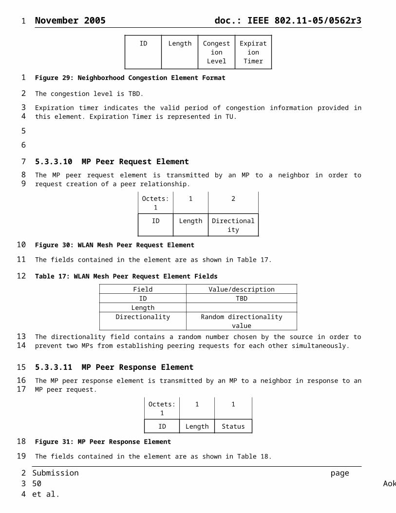
November 2005 doc.: IEEE 802.11-05/0562r3
If an MP is unable to detect any neighbor MPs, it shall adopt the Mesh ID for its highest priority profile, and proceed to the active state, which, in the case of a MAP is the access point initialization state. This will occur when the MP is the first device to power on (or multiple MPs power on simultaneously). Any peer MP links will be established later as part of the continuous mesh formation procedures.
6.3.2 Mesh Link OperationsThe following sections describe how links are formed and maintained.
6.3.2.1 Peer Link Setup The purpose of this procedure is to establish at least one, and in many cases several, initial Mesh links with one or more peer MP.
A MP must be able to establish at least one Mesh link with a peer MP, and may be able to establish many such links simultaneously. It is possible that there are more candidate peer MPs than the device is capable of being associated with simultaneously. In this case, the MP must select which MPs to establish peer links with based on some measure of signal quality, such as gathered during the discovery phase, or other statistics received from candidate neighbor MPs.
Procedures for establishing and maintaining each peer link are described in Section 6.3.2.1.1. This procedure shall be followed for each candidate peer MP in priority order, until the maximum number of peers that the MP is configured to support is established.
Each attempt to establish a peer association with a neighbor MP may fail, in which case that MP shall be marked as no longer being a peer candidate in the MP neighbor table.
Peer links are terminated either explicitly by one of the peers issuing a “disconnect” to the other, or it is terminated implicitly because of a timeout. The duration of the timeout depends on the status of the link.
6.3.2.1.1 Peer Link Maintenance ProceduresA mesh point shall continue to look for received beacons on any of the unified channel graphs it is operating on. On receipt of a beacon from an unknown neighbor MP, but containing a matching Mesh ID, an MP shall attempt to create a peer link to the neighbor MP.
Active MPs shall include a WLAN Mesh Capability element in all transmitted beacon and probe response frames. The WLAN Mesh Capability element is defined in Section 5.3.3.1.
When included in a beacon or probe response frame transmitted by an MP, the WLAN Mesh Capability element shall indicate active MP status.
The WLAN Mesh Capability element includes a peer capacity field, which shall be set to a value indicating the number of additional peer associations that can be supported.
A peer MP link is directional, that is, one end is designated subordinate and the other superordinate. The superordinate end of the link corresponds to the MP that transmitted an association response that accepted an association request from the other MP.
An MP attempting to create a peer link with another MP shall transmit an association request frame to it, including an MP peer request element. This distinguishes a peer MP association request from a client association request. For each attempt, a new randomly selected number shall be selected and transmitted in the directionality field. Once the association request has been successfully transmitted, the neighbor state shall be set to association pending and the directionality field noted.
If an association request is received from the candidate peer whilst the state is set to association pending, and contains an MP peer response element with status set to deny, the state shall be changed to candidate peer.
On receipt of an association request containing an MP peer associate request element, an MP shall check the state of the requesting MP in its own neighbor table. If the state is set to association pending, it shall compare the directionality value contained in the MP peer associate request element with that contained in its own table entry. If the received value is less than or equal to the transmitted value stored in the table, the MP shall reject the association request by transmitting an
Submission page 50 Aoki, et al.
1
1234
56
789
10111213
141516
1718
1920
21222324
2526
2728
2930
313233
34353637
3839
40414243
2
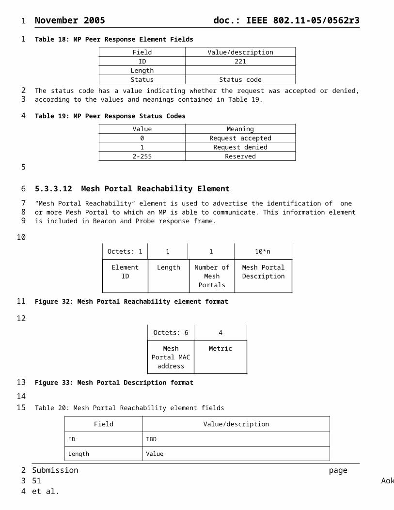
November 2005 doc.: IEEE 802.11-05/0562r3
association response containing an MP peer response element with status set to deny. Otherwise, it may accept or reject the association request at its option.
6.3.2.2 Local Link State DiscoveryThe purpose of the local link state discovery procedure is to populate the r and ept fields for each peer MP in the neighbor table. These are subsequently used by the route establishment algorithm to determine the most efficient available routes.
By definition, a peer link is considered “down” when there is no value assigned to the r and ept fields. As soon as an initial local link state discovery is completed, and the values are assigned, the link is considered “up” and remains so until a disassociation event. Since all such links created during initialization are “down”, the state transitions from subordinate, link down, to subordinate, link up, on completion of each link discovery.
The procedures for local link state discovery and maintenance are described in Section 6.3.2.2.1.
As soon as the first peer link is in an “up” state, the MP may start to receive frames attempting to establish paths. In this case, it shall ignore any such frames until it has completed local link state discovery for all of its peer links.
6.3.2.2.1 Local Link State Maintenance ProceduresAll Mesh links are asymmetric, in that a pairwise link consists of one node designated as superordinate and one designated as subordinate.
In order to ensure that the measured link state is symmetric, the superordinate node is responsible for making a determination as to the link quality. It may use any method it chooses, but must make a determination as to the following two parameters:
r current bit rate in use, that is, the modulation mode
ept packet error rate at the current bit rate for a data frame with a 1000 byte payload
A superordinate node shall make this determination for a link in the superordinate, down, state and at future intervals at its option. On making such a determination, it shall include the information in a local link state announcement frame and transmit it to the subordinate node. On successful transmission of the frame, it shall update the values in its neighbor MP table with the new values, changing the state from superordinate, down to superordinate, up if this is an initial assessment.
A subordinate node shall update the values in its neighbor MP table whenever a local link state announcement message is received.
6.3.2.3 Mesh Portal Discovery (Optional)Depending on the configuration of the network and the selected profile, a mesh point may be able to discover the presence of a portal in the mesh network. The mechanism to discover the presence of portals is described in section 6.4.3.1.5.1.
6.3.3 Channel Selection
6.3.3.1 Channel Selection Modes for Mesh Point Logical Radio InterfacesA Mesh Point shall specify the channel selection mode of each logical radio interface as either simple unification mode or advanced mode, and advertise this mode using the simple channel unification mode flag in the mesh capability element included in beacon and probe response frames.
A mesh point logical radio interface that is in simple unification mode shall select a channel in a controlled way such that it enables the formation of a unified channel graph that becomes merged and hence fully connected. The mesh point logical radio interface shall establish links with neighbors that match the Mesh ID and Mesh Profile and select its channel based on the highest channel precedence value.
A mesh point logical radio interface that is in advanced mode may set its channel based on advanced management rules (beyond the scope of this proposal). In this mode, the mesh point logical interface shall establish links with neighboring
Submission page 51 Aoki, et al.
1
12
3
456
789
10
11
1213
141516
1718
19
20
21222324
2526
272829
30
31323334
35363738
3940
2
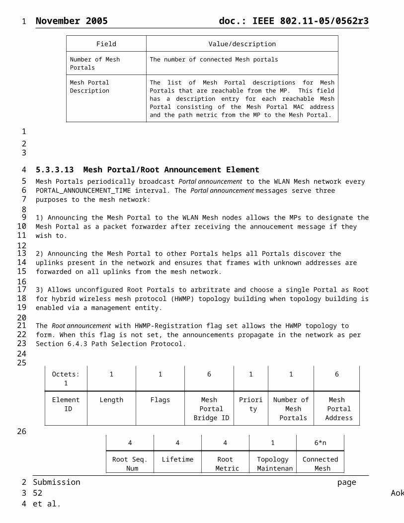
November 2005 doc.: IEEE 802.11-05/0562r3
mesh point logical interfaces that match the Mesh ID and Mesh Profile that are on the same channel as the logical interface according to the advanced channel setting rules.
6.3.3.2 Simple Channel Unification ProtocolThis protocol is executed on mesh point logical radio interfaces that are configured in simple unification mode
At boot time, an MP logical radio interface that is configured in simple channel unification mode shall perform passive scanning to discover neighboring MPs. If an MP is unable to detect any neighbor MPs, it shall adopt the Mesh ID for its highest priority profile, select a channel for operation, and select an initial channel precedence value. The initial channel precedence value may be initialized to the number of microseconds since the boot time of the mesh point plus a random value.
In the event that a mesh point logical radio interface that is configured in simple channel unification mode discovers a disjoint mesh, that is, the list of candidate peer Mesh Points spans more than one channel, it shall select the channel that is indicated by the candidate peer Mesh Point that has the numerically highest channel precedence indicator to be the unification channel.
If the identified unification channel is different than the current operating channel of the mesh point logical radio interface, the mesh point shall execute the channel cluster switch protocol described in Section 6.3.3.3.
6.3.3.3 Channel Cluster Switch ProtocolThis section describes the procedure used for a mesh point to initiate switching of a unified channel graph to a new channel, with a new channel precedence indicator. Due to the possibility of more than one mesh point of a channel cluster executing this procedure concurrently, this procedure includes a mechanism to resolve such possible conflicts by introducing a channel switch wait timer that assures adequate time for the decision process of this procedure.
The mesh point that determines the need to switch the channel of its cluster first chooses a channel cluster switch wait timer of TBD time units (TUs). The mesh point sets a local timer with this wait time and then sends a channel cluster switch announcement frame to each peer mesh point to which an active association exists in the unified channel graph, copying the value of the new candidate channel and new candidate channel precedence indicator and setting the channel switch wait time to TBD TUs.
If a mesh point receives a channel cluster switch frame with a channel precedence value larger than the current channel precedence value of the logical interface on which the frame was received, the mesh point shall set a channel cluster switch timer equal to the channel switch wait timer value of the frame and then sends a channel cluster switch announcement frame to each peer mesh point to which an active association exists on the logical radio interface, copying the values from the received channel cluster switch announcement frame.
Note that it is possible that more than one mesh point in the unified channel graph may independently detect the need to switch channels and send separate channel cluster switch announcement frames. If a mesh point receives more than one channel cluster switch announcement frame, it only acts upon the frame if the channel precedence value is larger than the channel precedence value of a previously received channel cluster switch announcement frame. In case a newly received channel cluster announcement frame has the same channel precedence value as a previously received frame, the new frame is acted upon only if the source address is smaller than the source address from the previously received frame. If the mesh point acts upon the newly received channel cluster switch frame, it updates its candidate channel and candidate channel precedence indicator, sets its channel cluster switch wait timer to the channel switch wait value of the frame and then sends a channel cluster switch announcement frame to each peer mesh point to which an active association exists on the logical radio interface, copying the values from the received channel cluster switch announcement frame.
If a channel switch wait timer has been set on a mesh point, the mesh point shall not originate a new channel cluster switch announcement frame during the duration of the channel switch wait timer. When the channel cluster switch wait timer expires on a mesh point the mesh point switches its radio interface to the candidate channel and updates its channel precedence indicator to the candidate channel precedence indicator.
6.3.4 MP Boot Sequence (Informative)At power up, a configured MP shall perform the following sequence of operations:
Submission page 52 Aoki, et al.
1
12
34
56789
10111213
1415
1617181920
2122232425
2627282930
31323334353637383940
41424344
4546
2
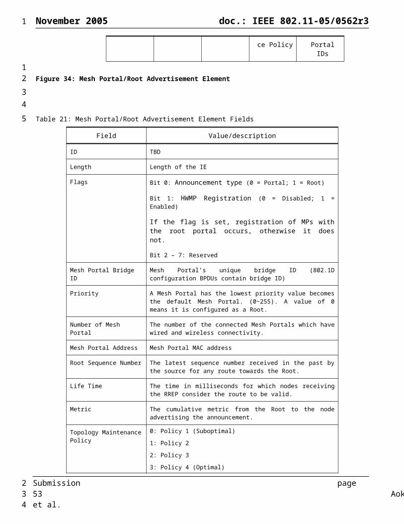
November 2005 doc.: IEEE 802.11-05/0562r3
1. Passive scanning to discover other MP
2. Channel selection
3. Begin mesh beaconing.
4. Neighbor MP link establishment1
i. 802.11 open authentication
ii. Association
iii. 802.11i authentication and key exchange
5. Local link state measurement
6. Path selection initialization
7. AP initialization (optional – if MAP)
This sequence is illustrated in Figure 55.
Link establishment may be performed with a number of nodes but not all of the links will become active – that depends on the outcome of the link state measurements and on the routing initialization. The final (optional) step of the boot sequence is AP service initialization. This may be observed as a Mesh AP (MAP) starting to transmit a valid SSID information element in beacons. Before this point, that is, before the path selection specific state has been initialized, the MAP will not accept association requests or probe requests from simple STA devices. After this time, however, the MAP will continue to perform maintenance operations on the path selection state.
Figure 55: Mesh Point Boot Sequence
6.3.5 MP Tables (Informative)
1 Neighbor MP link establishment may be repeated multiple times if there are multiple neighbor MPs
Submission page 53 Aoki, et al.
1
1
2
3
45
6
7
8
9
10
11
121314151617
1819
2021
2
3

November 2005 doc.: IEEE 802.11-05/0562r3
6.3.5.1 MP Neighbor TableAn MP shall maintain a table containing an entry for each discovered neighbor MP. By definition, all neighbor MPs have the same Mesh ID. Each entry shall contain the information shown in Table 24.
Table 24: MP Neighbor Table Entry
Value DescriptionNeighbor MAC address MAC address of the neighbor MP radio interface Primary MAC address Primary MAC address of the MP, if it has more than one radio
interfaceState State of the association with the neighborDirectionality Directionality value in previous association requestco Operating channel numberpl Channel precedence valuer Reference bit rate (modulation mode)ept PER for the reference frame size at the reference bit rateQ Received signal strength or quality (internal units)
The state of the association with the neighbor shall take one of the values shown in Table 25, and shall be initialized on discovery to neighbor or candidate peer based on beacon contents as described in section Error: Reference source not found.
Table 25: State Values
State DescriptionNeighbor Discovered, no peer capabilityCandidate peer Has peer capability, no association establishedAssociation pending Association sent, reply not receivedSubordinate, link down Association established with this node as the subordinate, link
not yet measuredSubordinate, link up Association established with this node as the subordinate, link
measured and activeSuperordinate, link down Association established with peer as the subordinate, link not
yet measuredSuperordinate, link up Association established with peer as the subordinate, link
measured and active
The neighbor MAC address is the address of the neighbor MP’s radio interface that was discovered. The state information for the link to the MP stored in the MP neighbor table entry is with respect to this advertised address.
The primary MAC address of a neighbor MP is the primary unique address of the MP. In the case where the neighbor MP has only one radio interface, the primary MAC address will be equal to the radio interface MAC address. In the case where the neighbor MP has more than one radio interface, the primary MAC address is typically the radio interface MAC address with the smallest address value. (Note: more than one table entry may be created for a given neighbor primary MAC address).
The operating channel number is the channel on which the beacon was received from the node.
The channel precedence value is a number chosen by all MP radio interfaces in a given Mesh. It is contained in the beacon transmitted by the neighbor MP. It is used when merging disjoint networks and for the purpose of supporting DFS.
The bit rate and PER values are created by the local link state discovery procedures, described in section Error: Referencesource not found.
The received signal strength or quality may represent any convenient quality measure; this value is never presented at an exposed interface, but rather is used for comparisons.
6.3.5.2 MP Proxy Table (Informative)Each MP maintains a proxy table for the devices outside of the WLAN Mesh. The format of a logical proxy table is shown below.
Submission page 54 Aoki, et al.
1
123
4
56
7
89
1011121314
15
1617
1819
2021
222324
2
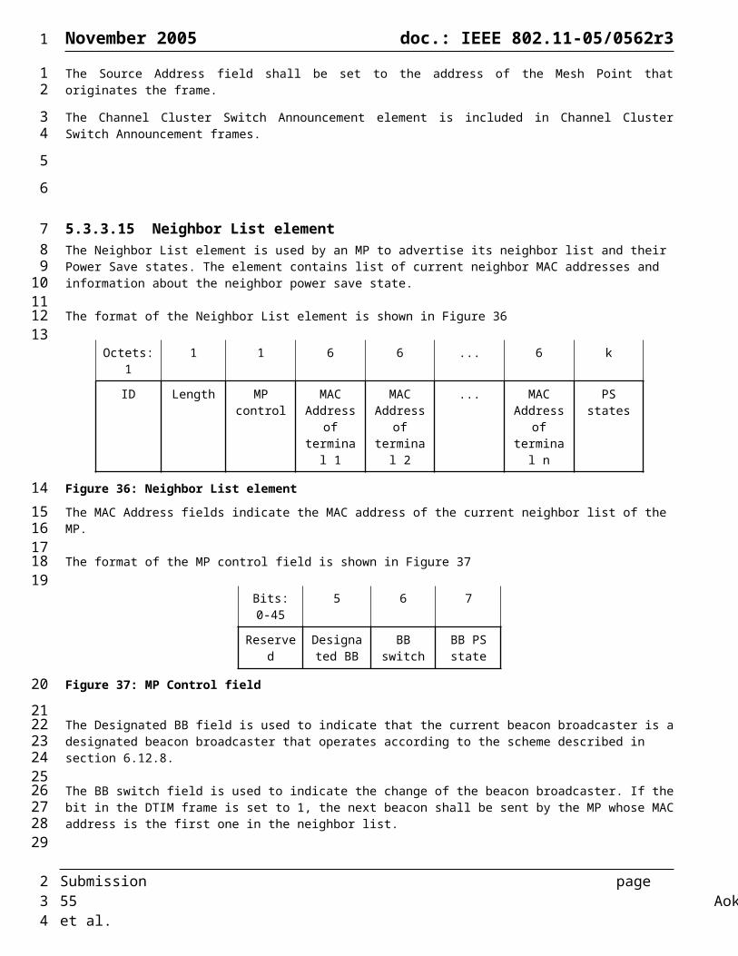
November 2005 doc.: IEEE 802.11-05/0562r3
Table 26: A logical proxy table maintained at each MP (the information can be derived from other sources).
Value DescriptionMAC Address MAC address of a given STA inMesh If the destination is within the meshisProxied If the destination is proxied by MAP/MPPOwner MAC address of its proxy
An example for proxy registration procedure (Figure 56): During the initialization phase, a STA first associates with MAP3 by using standard IEEE 802.11 procedures. Once associated, MAP3 may initiate a proxy registration procedure on behalf of STA towards the MPP. To do so, it sends a proxy registration request message on behalf of STA, to the mesh portal. MAP1 after receiving the registration request message updates its own proxy registration table for STA and forwards it towards mesh portal. The MPP thereby learns that STA is being proxied by MAP3. The MPP may then update its proxy registration table with new/updated entry for STA with owner set to MAP3 and inMesh, isProxied flags set to true. The MPP may then create a proxy registration reply message which is sent towards MAP3. Once MAP3 receives a registration confirmation for STA, proxy routing for STA is established. (Further optimization can be done using selective proxying).
Registration Table At MPP
Addr inMesh isProxied Owner
802.3 LAN No Yes MPP
STA Yes Yes MAP3
Registration Table At MAP1
Addr inMesh isProxied Owner
STA Yes Yes MAP3
Registration Table At MAP3
Addr inMesh isProxied Owner
STA Yes Yes MAP3
Registration Table At MAP2
Addr inMesh isProxied Owner
MPP
MAP2MAP1
MAP3
STA
802.3 LAN
Figure 56: Example of optional proxy registration procedure to MPP.
6.4 Mesh Path Selection and Forwarding
6.4.1 OverviewThe terms “mesh path selection” and “mesh forwarding” are used to describe selection of single-hop or multi-hop paths and forwarding of data frames across these paths between mesh points at the link layer. Data messages use the 802.11-1999 standard four address format, with 802.11e extensions for 802.1p tag transfer, plus some additional mesh specific information. Simple client STA nodes associate with one of the Mesh AP devices as normal, since the Mesh AP devices are logically a collection of APs that are part of the same ESS.
Path selection messages are also transported at the link layer, using 802.11 management frames (MMPDUs). Mesh path selection services consist of baseline management messages for neighbor discovery, local link state measurement and maintenance, and identification of an active path selection protocol. Each WLAN Mesh uses a single method to determine
Submission page 55 Aoki, et al.
1
12
3
456789
10111213
1415
16
17
181920212223
242526
2

November 2005 doc.: IEEE 802.11-05/0562r3
paths through the Mesh, although a single device may be capable of supporting several. This section defines a path selection protocol targeted for small/medium unmanaged networks.
6.4.1.1 Extensible Path Selection FrameworkThis proposal specifies an extensible framework to enable flexible implementation of path selection protocols and metrics within the 802.11s standard framework. The proposal specifies a default mandatory protocol and metric for all implementations, to ensure baseline interoperability between devices from different vendors. However, the proposal also allows any vendor to implement any protocol and/or metric in the 802.11s framework to meet special application needs. A mesh point may include multiple protocol implementations (e.g., including the default protocol, optional protocols, future standard protocols, etc), but only one protocol will be active on a particular link at a time. Different WLAN Meshes may have different active path selection protocols, but a particular mesh will have one active protocol at a time.
As described in Sections 6.3.1.1 and 6.3.1.2, a mesh point uses the WLAN Mesh Capability Information Element to discovery which protocol and metric an established WLAN Mesh is using, allowing the mesh point to identify if and how it should participate in the mesh. Note that this proposal does not force an existing WLAN Mesh that is using a protocol other than the default protocol to switch to the “least common denominator” protocol when a new mesh point requests association. While it is possible, in principle, to implement such behavior, an algorithm to coordinate such reconfiguration is beyond the scope of this proposal.
6.4.2 Path Selection MetricsAs described above, the proposed 802.11s extensibility framework allows, in principal, a WLAN Mesh to be implemented with any path selection metric(s). This section defines a default radio-aware path selection metric to enable baseline interoperability. Figure 57 shows an example path metric based on airtime costs.
6.4.2.1 Airtime Link Metric Function Computation ProceduresIn order to compute the unicast forwarding table from the cached link state information generated by each node, the MP must first calculate the link cost for each pairwise link in the Mesh. This section defines a default link metric that may be used by a path selection protocol to identify an efficient radio-aware path. Note that the extensibility framework allows this metric to be overridden by any routing metric as specified in the active profile.
The cost function for establishment of the radio-aware paths is based on airtime cost. Airtime cost reflects the amount of channel resources consumed by transmitting the frame over a particular link. This measure is approximate and designed for ease of implementation and interoperability.
The airtime cost for each link is calculated as:
Where Oca, Op and Bt are constants listed in Table 27, and the input parameters r and ept are the bit rate in Mbs-1 and the frame error rate for the test frame size Bt respectively. The rate r is dependent on local implementation of rate adaptation and represents the rate at which the mesh point would transmit a frame of standard size ( Bt) based on current conditions. ept
estimation is a local implementation choice and is intended to estimate the ept for transmissions of standard size frames (Bt) at the current transmit bit rate that is used to transmit frames of that size (r). Packet drops due to exceeding TTL should not be included in this estimate as they are not correlated with link performance.
Table 27: Airtime Cost Constants
Parameter Value (802.11a)
Value (802.11b) Description
Oca 75s 335s Channel access overheadOp 110s 364s Protocol overheadBt 8224 8224 Number of bits in test frame
Submission page 56 Aoki, et al.
1
12
3456789
10
111213141516
17181920
2122232425
262728
29
30
313233343536
37
38
2
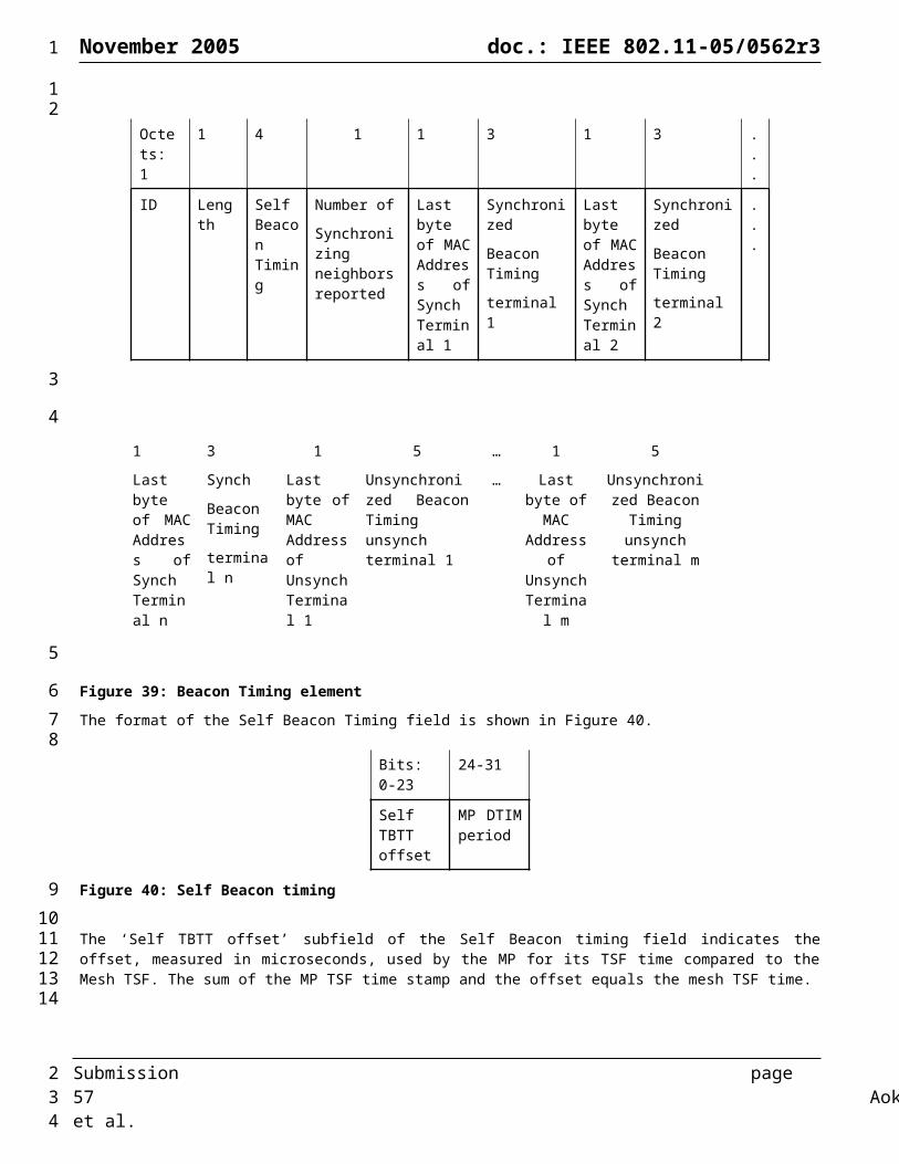
November 2005 doc.: IEEE 802.11-05/0562r3
Figure 57: Example Unicast Cost Function based on Airtime Link Metrics
6.4.3 Path Selection ProtocolThis section describes two example path selection protocols that can be implemented in the extensible 802.11s framework. The first protocol described in Section 6.4.3.1 is the default path selection protocol that must be implemented on all 802.11s devices to ensure interoperability. The second protocol, described in Section 6.4.3.2, is an additional optional protocol. Note that the extensible path selection framework allows these or any other path selection protocols to be implemented in the 802.11s framework.
6.4.3.1 Hybrid Wireless Mesh Protocol (HWMP): Default path selection protocol for interoperability
6.4.3.1.1 IntroductionThe Hybrid Wireless Mesh Protocol (HWMP) is a path selection protocol that combines the flexibility of on-demand route discovery with extensions to enable efficient proactive routing to mesh portals. The hybrid nature of HWMP enables flexible path selection that is easily adapted to both infrastructure and ad hoc stand-alone mesh network deployments.
HWMP combines on-demand routing capabilities and pro-active, tree based routing capabilities. This combination allows mesh points to perform the discovery and maintenance of optimal routes themselves or to rely on the formation of a tree structure based on a root node. In both cases, neighbour node selection is based on a predefined metric. HWMP uses a single set of protocol primitives derived from AODV for all topology and routing related functions. These are described in subsequent sections.
If a mesh network has no root node configured, (e.g. an unstructured network), on-demand route discovery is used for all routing in the mesh network.
Submission page 57 Aoki, et al.
1
12
3
4
56789
10
1112
13141516
1718192021
2223
2
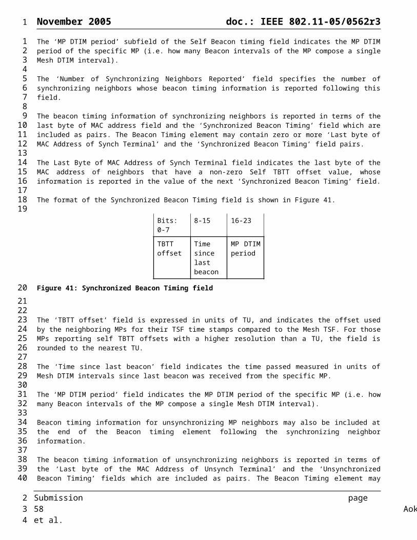
November 2005 doc.: IEEE 802.11-05/0562r3
A tree structured network is enabled by configuring a mesh point (typically a mesh portal) as a root node. In that case, other mesh points proactively maintain routes to the root node and a proactive, distance vector routing tree is created and maintained.
HWMP enables simple hybrid path setup: if a proactive tree exists it may be used by default while on-demand route discovery is in progress.
As described in the following sections, the following are some of the key benefits of the HWMP hybrid routing approach:
Flexibility to adapt to the requirements of a wide range of scenarios, including fixed to mobile mesh networks
Mesh points discover and use the best-metric path to any destination in the mesh with low complexity
In addition, when a root node is configured in the mesh:
o Flooding of route discovery packets in the mesh is reduced if the destination is outside the mesh
o The need to buffer messages at the source while on-demand route discovery is in progress is reduced
o Non-discovery broadcast traffic can be delivered along the tree topology
o On-demand routes have the topology tree to fall back on should an on-demand route become unavailable or during route re-discovery
6.4.3.1.2 On Demand Routing in HWMPOn demand routing in HWMP uses a Route Request (RREQ) and Route Reply (RREP) mechanism to establish routes between two nodes. It is assumed that each node has some mechanism to determine the metric cost of the link to each of its neighbors. In order to propagate the metric information between nodes, a metric field is used in the RREQ and RREP messages. When a node S wants to find the route to a destination D, it broadcasts a RREQ with the destination node D specified in the destination list and the metric field initialized to 0.
Each node may receive multiple copies of the same RREQ that originated in S, each RREQ traversing a unique path from S to the node. When a node receives a RREQ it creates a route to S or updates its current route if the RREQ traversed through a route that offered a better metric than the current route to S. If a route is created or modified, the RREQ is also forwarded (re-broadcast).
Whenever a node forwards a RREQ, the metric field in the RREQ is updated to reflect the cumulative metric of the route to the RREQ’s source from that the forwarding node. After creating or updating a route to S, the destination node D sends a unicast RREP back to S.
Intermediate nodes DO NOT generate a RREP even if they have a route to the destination. Only the destination node can generate a RREP. Intermediate nodes create a route to D on receiving the RREP, and also forward the RREP toward S. When S receives the RREP, it creates a route to D. If the destination receives further RREQs with a better metric, then the destination updates its route to the source to the new route and also sends a fresh RREP to the source along the updated route. Thus a bidirectional, best end-to-end metric route is established between nodes S and D.
Route Maintenance (Optional Implementation Enhancement)
Due to the dynamics of a wireless environment, it is possible that the initial best metric route established using the above mentioned RREQ/RREP mechanism may become worse or that other routes may become available that provide a better end-to-end metric. To maintain a best metric path between nodes, each active source node sends a periodic RREQ message (maintenance RREQ) for the destination(s) that it is communicating with. Maintenance RREQs enable the nodes to adapt to the changes in the network conditions and help to maintain best metric routes between nodes. The time between two consecutive maintenance RREQs is referred as a refresh-round. Maintenance of best metric routes using the above mentioned feature is an optional feature. Route-maintenance is driven by the source node and the rest of the nodes do not need to do any special processing of control packets generated during the maintenance phase. Specifically, processing of maintenance RREQs is the same as processing of RREQs generated during the discovery phase.
Submission page 58 Aoki, et al.
1
123
45
6
7
8
9
10
11
12
1314
15
161718192021
22232425
262728
2930313233
34
3536373839404142434445
2
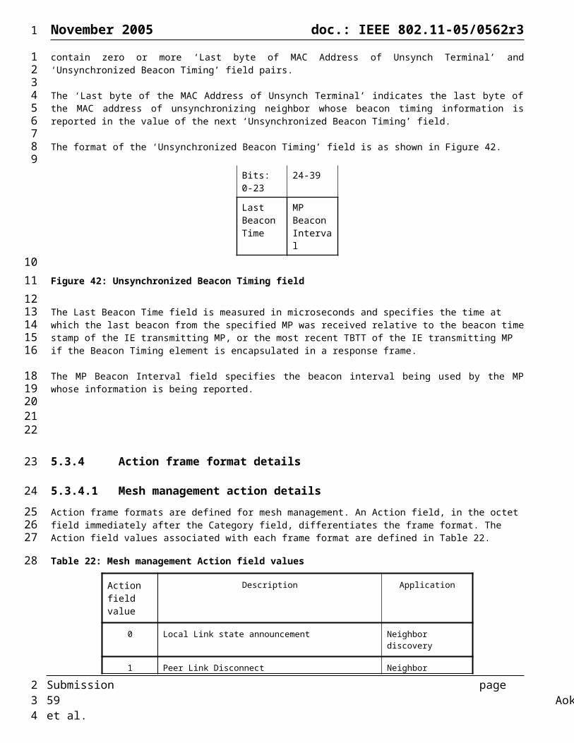
November 2005 doc.: IEEE 802.11-05/0562r3
When a RREQ propagates through the network, nodes that already have best metric routes to the originator may learn lower quality metric routes to the originator before receiving information through the current best metric route. Hence, a form of route selection hysteresis is used to improve route stability by not immediately switching to a worse metric route than the best-known route. Hysteresis allows a good route to continue to be used for a period of time either when a RREQ message that would normally propagate along the best path is lost or when a new worse metric RREQ is seen before the best metric RREQ is seen during a particular round.
Best Candidate Route Caching (Optional Implementation Enhancement):
However, during each refresh round, the best new route and metric learned during that round (called candidate route) is cached. In the case where hysteresis prevents the immediate switch to a new route early in a round, but the node learns later in the round that the metric of the current route (selected during a previous round) has degraded, it is able to immediately switch to a better-metric candidate route learned earlier in the same round. This mechanism guarantees that nodes in the network are always able to update a route based on the best metric learned during each round while simultaneously maintaining stable routes when a small number of RREQ messages are lost along the currently used best metric route.
On-demand Routing uses a sequence number mechanism to maintain loop-free connectivity at all times. Each node maintains its own sequence number, which is propagated to other nodes when the node originates control messages (RREQ or RREP).
6.4.3.1.3 Tree Based routing in HWMPIf a mesh point (typically a mesh portal) in a WLAN Mesh is optionally configured as a root node, other mesh points proactively maintain routes to the root node using topology discovery primitives HWMP topology formation begins when the Root Portal announces itself with the Root announcement message that contains the distance metric and a sequence number. The value of the metric is zero. Any MP hearing the announcement directly updates its Route table as directly connected child of the Root and the metric associated with the link. It then rebroadcasts the Root announcement with an updated distance vector metric. Thus, the topology builds away from the Root as each MP updates the distance vector to Root and re-advertises to its neighbors the cumulative cost to the Root Portal.
Root Announcements are broadcast periodically by the root mesh portal with increasing sequence numbers. The HWMP-Registration flag further distinguishes between a uni-directional tree from all MPs to the root portal and a complete tree where MPs “register” with the root portal in order to set up paths from the root portal to all MPs. If the HWMP-Registration flag is not set in the announcement, there is no further processing of the Root Announcement Message at individual MPs beyond propagating the advertisement to neighbors. If the HWMP-Registration flag is set in the announcement, each MP stores the announcement and waits for a pre-defined period for other announcements to arrive. After the period is expired, the MP may send out a 1-hop broadcast RREQ including the destination address of the Root, as learned from the Root Announcement, to re-validate the advertisements heard from neighbor MPs. Each one-hop neighboring MP hearing the RREQ may reply with a RREP with the most up-to-date cost metric if it has a valid path to the Root. If it does not have a valid path to the Root, a neighboring MP may reply with an infinite metric or a RERR or it may not reply at all. The MP chooses the parent with best metric and caches others as potential parents upon hearing RREPs. An MP may attempt 1-hop broadcast RREQ retries.
If an MP does not hear a Root announcement message for a pre-defined period or does not receive a valid path to the Root from 1-hop broadcast RREQs and retries, it does not participate in tree-building until hearing a valid Root announcement again. It
Once an MP selects a parent MP for its path to the Root, it maintains the path by periodically sending maintenance RREQ to the parent MP and receiving an RREP back. It also proactively broadcasts topology RREQs and compares the replies with its current cost metric to make sure that it always has the best path to the Root (the broadcast interval facilitates optimization of the path to the Root on an ongoing basis and is much longer than the maintenance interval). Whenever the current parent is unable to provide the best path for three consecutive maintenance periods, the MP may switch to another parent depending on the policy configured on the Root (see Section 6.4.3.1.5.5). If the current parent path is lost, the MP broadcasts the topology RREQ immediately and sends out an RERR down the topology so that any node with an on-demand route containing this link can remove the entry from the route table. The same RERR is sent up the tree for the same purpose after another parent is found. Note that topology paths do not require updating unless finding another parent MP fails. If another parent MP with a valid path to the Root cannot found for a pre-defined interval, a RERR with “all” flag issued to all children MPs advertising the loss of the path to the Root.
Submission page 59 Aoki, et al.
1
123456
7
89
1011121314
151617
1819202122232425
262728293031323334353637
383940
4142434445464748495051
2

November 2005 doc.: IEEE 802.11-05/0562r3
If the HWMP-Registration flag was set in the Root announcement message, when an MP selects a parent MP for its path to the Root it registers itself with the Root by sending a “Gratuitous RREP” message containing its own address as well as all connected STAs. Each intermediate MP on the way to the Root seeing the “Gratuitous RREP” message, updates the MP it was received from as the next-hop child to reach the source MP (they are not required to learn about STA addresses). Thus the Root learns about all nodes in the mesh network. When MPs change parent (at will or forced by link/node outage) they always send a re-registration in the form of “Gratuitous RREP” to the Root causing each intermediate MP to update their route tables. The Root issues a RERR with “all” flag on the old path of the MP.
When a node wants to send a frame to another node, and if it has no route to that root (mapping its address to a given MP) it may send the frame to the Root. The Root checks to see if the packet is intended for a node within the mesh or outside. It forwards the message on its uplink if it cannot find an entry in its mesh side routing table. If it does find an entry in the mesh, it sends the frame to the destination parent MP with a special TA. When the packet reaches the destination parent MP and it sees the special source address, it knows that the address is within the mesh and may initiate a RREQ back to the source. This hybrid routing mechanism allows the intial frame to be forwarded on the tree topology path followed by establishing an optimal, on-demand route between the source-destination pair for all subsequent frames between them. Any frame sent from the Root follows the optimal metric path to any other MP in the network.
When there are multiple Portals in a mesh network, a single Portal takes the Root role either by provisioning or by a dynamic procedure. All other Portals assume non-Root roles. In the presence of multiple Portals, the Root forwards all frames with unknown addresses outside the mesh to its own uplink as well as other Portal uplinks. All non-Root Portals forward frames from outside the mesh to the Root Portal for further forwarding within the mesh network. Should multiples Portals be connected to the same LAN segment, an external STP running in the LAN segment may block the wired uplink of a Portal. This occurs by the virtue of Portals transporting BPDU frames between them as data frames.
6.4.3.1.4 On Demand Routing Protocol Details
6.4.3.1.4.1 Message Generation and ProcessingThis section describes the steps involved in the generation and processing of RREQ and RREP messages. Figure 78, Figure79, and Figure 80 provide a detailed flowchart of the processing of these messages. In this section, and in the rest of this document, fields in routing messages (format of the messages are provided in Section 5.3.3) will be referred to as msg.field. For example, rreq.source refers to the Source field in the RREQ message. Note: rreq.destination[] refers to the list of destinations in the RREQ.
On-Demand Routing determines routes to destinations and populates a routing table. Each route table entry contains the following fields.
destination – The address of the destination seq# – Sequence number of the mesh destination, which determines the “freshness” of the route. A value of 0 indicates
that the sequence number is unknown. nexthop – The address of the immediate neighbor node to which any data packet for the destination should be forwarded egress_if – The ID of the interface on which the nexthop exists hopcount – Number of hops to the destination metric – Cumulative metric from this node to the destination using this route list_of_precursors – neighbor node addresses to which a route reply was generated or forwarded on this route lifetime – Time until which this route is valid. last_update_time – Time when this route was updated by a control packet. cand_rt (optional) - Best-metric route seen so far in the current refresh round. This route has the following fields:
a. valid – TRUE indicates alternate route is validb. seq# - Sequence number of the destinationc. nexthop - The address of the immediate neighbor node to which we have to forward any data packet for the
destination using this routed. metric – Cumulative metric from this node to the destination using this routee. hopcount – Number of hops to the destination
6.4.3.1.4.1.1 Generating RREQsA node that is a source of some data traffic may generate a RREQ under two different conditions:
Submission page 60 Aoki, et al.
1
1234567
89
101112131415
161718192021
22
232425262728
2930
3132333435363738394041424344454647
4849
2

November 2005 doc.: IEEE 802.11-05/0562r3
Route Discovery : When it has some data to be sent to a destination D, and it does not have a route to D (Triggered RREQ). The data may have originated in the same node or from an STA associated to this node. In this case, the node generates a RREQ that has D as a member in the destination list of the RREQ
Route Refresh/Maintenance (optional) : Once every HWMP_RREQ_REFRESH_PERIOD (Maintenance RREQ) for each destination that was not updated by a control message (RREQ or RREP) from the destination since (current_time) - (HWMP_RREQ_REFRESH_PERIOD) + (2*HWMP_NET_TRAVERSAL_TIME). The node can generate one RREQ per destination or optionally, to reduce congestion in the network, it may generate one RREQ and include all destinations.
After a node attempts to find a route by sending a RREQ, the node waits for a route to be found (through the receipt of a control message originating from the new destination nodes). If some of the destinations specified in the RREQ sent are still unknown after HWMP_RT_NETDIAMETER_TRAVERSAL_TIME (after the RREQ was sent), then the node MAY send a RREQ again (retry) with the list of unknown destinations at that time. The RREQ retry process may be repeated up to a maximum of HWMP_MAX_RREQ_RETRIES times. The retry process MUST use a binary exponential back-off mechanism similar to AODV. In order to limit the number of RREQs generate, on-demand routing uses a RREQ rate limiting threshold similar to AODV.
Before sending a RREQ (a fresh one or a retry), the RREQ_ID of the node MUST be incremented. When a fresh RREQ is sent, the source’s sequence number MUST be incremented if it had not been incremented in the last HWMP_NETDIAMTER_TRAVERSAL_TIME. Optionally, the node may increment the source’s sequence number every time a fresh RREQ is generated. To prevent RREQ messages from causing network congestion, nodes MAY use the expanding-ring-search and RREQ rate-limiting mechanisms specified in [12]
Delayed Sequence Number Increment (Optional Enhancement):Before sending a RREQ, the RREQ_ID of the node is incremented. However, to improve route stability (and further reduce overhead), a source node’s route request sequence number may be maintained for a minimum time interval. The node’s sequence number is incremented only if the time the first RREQ was sent with the current sequence number is at least HWMP_RT_NETDIAMETER_TRAVERSAL_TIME before current_time. This mechanism prevents nodes from changing the route frequently to the source every time the source sends a burst of RREQs within a very short time (scenario4 in section Appendix A illustrates this situation with an example). This element of the protocol allows a source node to immediately initiate route discovery to a new destination on-demand without affecting recently refreshed routes to the source in other nodes.
6.4.3.1.4.1.2 Processing RREQsPropagation of RREQ messages through a mesh network has two major effects: 1) establish a route to the source of the RREQ at the destination and intermediate nodes, and 2) trigger a RREP from the destination node. When a node receives a RREQ, it may create or update a route to the source. If no route exists to rreq.source, or if the sequence number for the destination is unknown, then, a valid route MUST be created. If a route exists (current route), then, the source sequence number on the RREQ is compared to the sequence number on the route entry. If the sequence number in the RREQ is older, then it is dropped and no further processing is done.
Otherwise, the current route to the source is modified if any of the following conditions is true: rreq.metric plus the current metric to previous hop (new_metric) is better than the metric in the current route the RREQ is newer, and the source sequence number in the RREQ is greater than the sequence number in the route
entry by at least HWMP_RREQ_LOSS_THRESHOLD. Example scenario3 in section Appendix A illustrates this situation.
the previous hop is the same as the nexthop in the current route, and the candidate route is invalid (or not implemented)
the previous hop is the same as the nexthop in the current route, and the candidate route is valid, ando source sequence number in the RREQ is greater than the sequence number in the candidate routeo source sequence number in the RREQ is equal to the one in the candidate route and new_metric is better
than the metric in the candidate route
When a route to the destination is created or modified, the sequence number in the route entry is set to the source sequence number in the RREQ, the nexthop is set to the previous hop, the metric is set to new_metric, the hopcount is set to one more than rreq.hopcount, the last_update_time is set to the current_time, and the lifetime is set to current_time + HWMP_ACTIVE_ROUTE_TIMEOUT. Further processing is done only if the route was not created or modified.
Submission page 61 Aoki, et al.
1
123456789
101112131415161718192021222324252627282930313233
343536373839404142434445464748495051525354555657
2
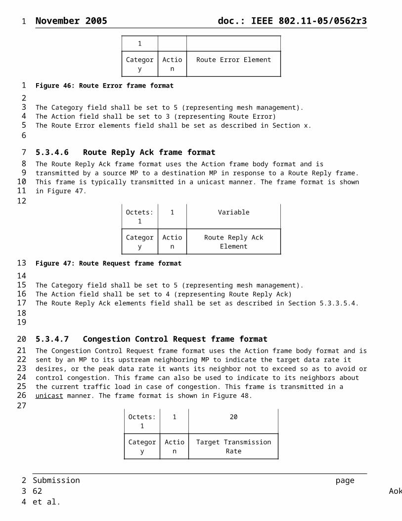
November 2005 doc.: IEEE 802.11-05/0562r3
If a newer RREQ (greater RREQ ID) was received from the previous hop node on the current route with a worse metric, then the current route is modified to reflect the new metric.
Best Candidate Route Caching (Optional Implementation Enhancement):If a newer RREQ came along a route that is different from the current route, it is examined to see if it could be used as a potential candidate route. If there is no candidate route, or if metric offered by the RREQ (new_metric) is better than the metric in the candidate route, then the candidate route is modified: the nexthop is set to the previous hop, the sequence number is set to rreq.osn, and the metric set to new_metric. A rreq_wait_queue along with an alarm (rreq_wait_alarm) set to go off in current_time + HWMP_NETDIAMETER_TRAVERSAL_TIME is created for <rreq.source, rreq.osn> if it is not present. The RREQ is added to the rreq_wait_queue if it is not in the queue already.
If any of the newer RREQs that arrive before the alarm goes off results in the modification of the current route, then the timer is canceled. If the current route is not modified, then, the metric offered by the RREQ is compared with the metric in the candidate route. If the candidate route’s metric is worse, then it is replaced with the route offered by the RREQ. Thus candidate route is maintained such that it provides a route with a metric that is second best to the current route.
If the RREQ is not dropped in the above processing, it is forwarded in the following cases: a route to the source was created the current route to the source was modified the RREQ-ID was not seen from the source before
In addition to the above scenarios, when the rreq_wait_alarm for a rreq_wait_queue goes off, all of the RREQs in the queue are forwarded (see Figure 79).
When a RREQ is forwarded, the information in the RREQ (specifically, source sequence number, metric and hopcount) set to the corresponding information in the (updated) route entry for the source. Whenever a RREQ is forwarded, and if the processing node is specified as a node in the rreq.destination[], then, a unicast RREP MUST be sent to the source along the current route. Before sending a RREP, the sequence number of the node MUST be incremented and the rrep.dsn is set to the incremented value.
The detailed steps for processing RREQ messages are shown in the flow chart in Figure 78.
6.4.3.1.4.1.3 Processing RREPsProcessing of RREPs is relatively simpler than RREQ processing. When a RREP is received, it is first determined if the destination sequence number in the RREP is newer than the sequence number in the route table entry for rrep.destination (if it exists). If a route existed and if the RREP is NOT newer, then the RREP is dropped. Otherwise, a route to the previous hop is created or updated if the previous hop is not the source of the RREP (rrep.destination). Note that if it is not a 1-hop route, and a route to the previous hop is created, then it will not have a valid sequence number. Then a route to rrep.destination is created or updated. The hopcount in the route entry is set to rrep.hopcount+1 and the metric is set to rrep.metric+(current metric to the previous hop). The hopcount and metric values from the route entry are then copied on to the RREP and the RREP is then forwarded towards rrep.source.
The detailed steps for processing RREP messages are shown in the flow chart in Figure 80.
6.4.3.1.4.1.4 Generation and Processing of RERRsThe generation and processing of RERR messages in on-demand routing are similar to the mechanisms in AODV [12].
6.4.3.1.4.2 Support for Legacy 802.11 StationsIn order to be compatible with legacy STA devices, Mesh APs generate and manage messages on behalf of the legacy STAs that are associated with them. The functionality is similar to the situation when a MAP has multiple addresses. The associated STAs addresses may be thought of as alias addresses for the MAP.
Submission page 62 Aoki, et al.
1
123456789
10111213141516171819202122232425262728293031323334
3536373839404142434445
464748
49505152
2

November 2005 doc.: IEEE 802.11-05/0562r3
The sequence numbers for the associated STAs MUST be maintained by the MAP. When the MAP receives a data packet from an associated STA to an unknown destination, it MUST generate a RREQ message for the destination. The source and source sequence number fields in the RREQ are filled with corresponding values for the STA. The MAP MAY also cache the data packets sent by the STA while the route is being discovered. Once the route is discovered, the data packets may be transmitted.
When a MAP receives a RREQ message in which the rreq.destination is that of an associated STA, then it MUST process the RREQ as if the rreq.destination was its own address.
If a MAP receives the disassociation frame or detects timeout of station association due to handoff, the MAP sends a RERR message to the MPs in the precursor list.
6.4.3.1.4.3 Route Table MaintenanceProcedures for Route Table maintenance are out of scope of this document. However, AODV [12] provides useful guidance.
6.4.3.1.4.4 Multiple interface operationThe protocol is extended to support mesh points that have two ore more WLAN interfaces. A mesh point that has multiple WLAN interfaces transmits RREQ frames using all of the interfaces that has are configured as part of the same WLAN Mesh. an MP that receives a RREQ frame on multiple interfaces selects the superior RREQ (using the metric comparison technique described above) and tracks which interface the superior RREQ was received on. When the destination MP receives the RREQ frame, each MP along the path transmits the RREP frame using the particular interface on which the superior RREQ message was received.
6.4.3.1.4.5 Path selection of source and destination pairsForwarding table entries may be uniquely defined for pairs of source and destination Mesh Points to avoid concentrating all traffic to a common destination (but from different sources) on an identical path. This allows traffic to the same destination but from different sources to be load balanced across multiple interfaces (and channels). When using this mode, if an MP has a forwarding table entry for a particular destination, the node may still generate and transmit a RREQ message when the source address does not match the forwarding table entry.
6.4.3.1.5 Tree based routing Protocol Details
6.4.3.1.5.1 Root Selection and ArbritrationRoot selection and arbitration only occurs if there exists at least one mesh portal in the mesh which is configured for topology building. Root selection and arbritration procedure ensures that there is always a single Root in the network regardless of the number of Portals present. All Portals start out in LEARNING state and emerges in Root and non-Root roles after a pre-defined PORTAL_ARBITRATION_TIME. Then they move to FORWARDING state and participate in HWMP topology formation. The following cases can occur in a mesh network:
1) No Portal exists: No tree-based topology is built and only On-demand routing is used
2) Portals exist but none has topology building enabled: No tree-based topology is built and only On demand routing is used.
3) Portals with topology building enabled exist but no Root configured: Each Portal sends Portal announcements and waits for PORTAL_ARBITRATION_TIME before assuming a Root role and sending out Root announcement messages. Each Portal hearing the Portal announcements examines the priorities in the messages and if it has a higher prority value than any priority value received during this period, it assumes a non-Root role. It assumes the Root role if it has a lower priority value than all other priorities received and sends Root announcement after PORTAL_ARBITRATION_TIME expires. The Root Portal saves all non-Root Portals as “MPs with uplinks” for future forwarding. All Portals move to FORWARDING state after this timer expired. Non-Root Portals use HWMP topology discovery and formation mechanisms like ordinary MPs to establish a path to the Root. They also maintain and optimize the path to the Root like ordinary MPs. When they are unable to find a path to the current Root Portal, may start advertising Portal announcement. The similar Root arbritration
Submission page 63 Aoki, et al.
1
12345
67
89
1011
12131415161718
192021222324
25
262728293031
3233343536373839404142434445
2

November 2005 doc.: IEEE 802.11-05/0562r3
process then selects a single Root Portal again. Note that all Portals hearing Portal announcement must send out Portal announcements with its own priority information.
4) Portals with topology building enabled exist and a single Root configured: A Root Portal configuration is advertised by the Root via a ‘0’ priority value in the Portal announcement message. Such a Portal waits for PORTAL_ARBITRATION_TIME in case there are other Root Portals as well before sending out Root announcements. A Root Portal learns about other Portals via the Portal announcements heard from non-Root Portals. All Portals hearing a Portal announcement message with ‘0’ priority value moves to FORWARDING state immediately. They then follow the same procedure as (2) as a non-Root Portal.
5) Portals with topology building enabled exist and multiple Roots configured: If two or more Portals start advertising themselves as Root by setting the priority value of ‘0’, the Roots with higher MAC addresses assume non-Root roles after the PORTAL_ARBITRATION_TIME. They follow the same procedure as (2) assuming non-Root Portal roles. If MPs hear multiple Root announcement messages, they must only attempt to build path with the announcement with lowest priority value and discard all others. Given the arbritration procedure between Portals, this period of time should be minimal and the MPs should need no extra mechanism for relying on a single Rooted tree.
6) A Portal with topology building enabled as well as higher priority emerges: Nothing happens if the current Root Portal is in FORWARDING state and the new Portal is able to hear it. Any announcements sent by the new Portal will be used by the Root to save it as an “MP with uplink”. The Portal regardless of its Root configuration assumes a non-Root role and follows the same procedure as (2). When it cannot hear the Root anymore, it may then start advertising Portal announcement with its appropriate priority value after the path to the Root is lost.
7) A Portal with topology building enabled as well as lower priority emerges: Same as (6)
8) A Portal leaves the topology: If the Portal had a Root role, the outage will be detected by the MPs as well non-Root Portals when a few consecutive Root announcements are not heard. The MPs move into the ad hoc should this occur. The non-Root Portals transition to LEARNING state and follow the procedures 1- 5 in attempt to re- build the topology tree. If the Portal had a non-Root role, the outage will be detected by the parent MP and a RERR will be triggered by the parent MP so that all MPs as well as the Root Portal may update their Route tables accordingly.
Multiple trees are not supported in a single network served by HWMP and at any time, there can only be a single Root in the topology. Typically, the MPs should only hear Root announcements from a single Root Portal. If they hear multiple Root announcements for a prolonged time, they should continue to ignore the announcements with higher priority value. Whenever Portals are able to hear each other, they should be formed into a single tree rooted at a single Portal based on the procedure above.
6.4.3.1.5.2 HWMP Topology FormationAll MPs startup in ad hoc state and the HWMP topology formation begins when a Root announcement message is received by them. The Root Portal sends out the Root announcements every ROOT_ANNOUNCEMENT_TIME with the sequence number monotonically increasing with every announcement and the TTL set to the maximum (255). As soon the announcement is received by an MP, it goes through the following procedure:
Set path to parent MP and Root Portal based on information received in Root announcement. Rebroadcast the announcement message by updating the metric in it and continue only if ‘HWMP Registration’ flag is set in the message
Move into the “Root Discovery” State and wait for ROOT_DELAY_TIME Move into the “Topology Formation” state and either (1) select a parent MP from all the MPs it received the
announcements from in the previous state; or (2) initiate a 1-hop broadcast RREQ in order to pull in all paths to the Root in case it did not receive them all or re-validate and select the most up-to-date and best path to the Root. The announcement contains the sequence number generated by the Root which ensures up-to-date use of the path information to the Root. If the MP chooses to re-validate the path to the Root, but exhausts RREQ retry mechanism, it must transition back to the “Root Discovery” state and wait for the next announcement to arrive.
Before moving to the next state, the MP chooses a parent MP with or without validation and moves to the “Registration” state.
An MP that has a known path to the Root must reply with RREP with Root as the destination address and its stored sequence number when they hear topology RREQ from other MPs. Only the MPs directly hearing the topology RREQ replies with
Submission page 64 Aoki, et al.
1
123456789
10111213141516171819202122232425262728293031323334353637
3839404142
43444546474849505152535455
2

November 2005 doc.: IEEE 802.11-05/0562r3
RREP and on-demand RREQ processing logic ignores topology RREQ messages completely. The MPs must not rebroadcast 1-hop broadcast RREQs. All MPs use On-demand methods of RREQ/RREP generating/processing rules with appropriate flags as described in Section 6.4.3.1.5.
After sending each 1-hop broadcast RREQs, the MP waits for TOPOLOGY_FORMATION_TIME and checks all the RREPs received. If no reply is received, it attempts 1-hop broadcast RREQ again and continues to retry this at a low rate. It chooses the best path to the Root from all the replies received and caches others as potential parents. Suitable potential links may be recognized and cached as “backup” and “alternate” links using similar procedure as IEEE 802.1w or any other mechanism. In combination with the topology maintenance function, this facilitates rapid recovery of small scale link loss. Each MP maintains the distance vector for the Root in the network at all times and supplies this information whenever requested by another MP.
6.4.3.1.5.3 Topology Formation when Proactive Registration Not EnabledIf the HWMP registration flag is not set in the root portal announcement, MPs propagate root announcement messages and proactively setup a path from all mesh points to the root portal. However, MPs do not proactively register with the root node in this case. Thus, paths from the root portal to all mesh points are not proactively maintained. This mode of operation, which may be configured on the Root node, consists only of the first step of the complete HWMP topology formation procedure as described in the previous section on HWMP Topology Formation.
A mesh portal periodically broadcasts its existence, when it is configured to do so (topology building is enabled). The chosen root portal broadcasts root announcements periodically. Mesh points that receive such a root portal announcement, set up paths to their parent node and to the root mesh portal, include their distance/path metric to the announced root portal, and rebroadcast the root announcement. Eventually, all nodes know a path to the root portal with shortest distance/best path metric. The next hop towards the root portal is the mesh point from which the best root portal announcement has been received.
The format of the root portal announcement information element is described in Section 5.3.3.13. The root portal increments its destination sequence number before sending a new root portal information element.
When a mesh point receives a root portal announcement information element, it will process it with the following steps:
The mesh point creates or updates a routing table entry to the sender of the root portal announcement. This is the path to its parent node. The destination and next hop for this entry are taken from the source address field (TA/addr2) of the management frame containing the root portal announcement information element. This route does not have a valid sequence number. The path metric is based on local knowledge.
The TTL value, the hop count value, and the path metric values in the route request message are updated (TTL := TTL-1; hopcount := hopcount+1; path metric values according to routing metric specification).
The mesh point creates or updates the forward route to the root portal. If a route to the root portal already exists, the root portal announcement information element is only used if it contains newer or better information. The latter means, that a route reply information element with the same destination sequence number but a better path metric value is considered.The route may be marked as path to the root portal in the routing table.
If TTL >0 in the updated root portal announcement IE, the mesh point broadcasts the updated root announcement information element.
The mesh point saves the value of the HWMP registration flag to a local variable. The value is connected with a timer, that expires after the same time as the proactive route to the root mesh portal will expire. The timer is reset, when a new root portal announcement is received. Since this section is about lightweight HWMP topology formation, the value of the HWMP registration flag is 0.
When a mesh point S wants to send a data frame to destination D, but there is no path to D in the routing table, it starts a On-demand route discovery for D. If D is inside the mesh, a path to D will be established. If D is outside the mesh and a mesh portal has learned D’s address from some other segment, the mesh portal will answer the route request, so that data frames destined for D are sent to that portal. If the route discovery fails, the data frame is sent to the root mesh portal to deal with it.
When a data frame destined for S arrives at the root portal from outside the mesh, the root portal looks up its routing table. A route to S might already exist. If not, a route discovery for S is performed by the root portal.
Submission page 65 Aoki, et al.
1
123
456789
10
111213141516
171819202122
2324
25
26272829
3031
32333435
3637
38394041
42434445
4647
2

November 2005 doc.: IEEE 802.11-05/0562r3
6.4.3.1.5.4 RegistrationWhenever an MP chooses a new parent in the tree, it checks the HWMP-Registration flag in the Root announcement message. If this flag is set, it sends a gratuitous RREP to register with the root as described below. Otherwise, it does not register with the root. As soon as an MP chooses the parent, it sends the gratuitous RREP message with the first source address as its own and rests all of its associated STAs to the Root. These gratuitous RREP messages are needed by the Root in order to keep the mapping of all known addresses within the mesh network with their parent MPs and facilitate ‘Rbridge-type’ forwarding between Root and nodes inside the mesh for communicating with outside the mesh. The registration messages may need reliable delivery to the Root in order to make sure that the Root always has the most up-to-date information. As the MPs move to the “Forwarding” state only after completing registration with Root, the Root sends RREP-ACK back to the MP so that the MP can move and start forwarding packets on the topology. All unicast, multicast and broadcast forwarding can occur over the topology from this point.
Each intermediate MPs hearing the gratuitous RREP adds the MP address contained in the message to its forwarding table. This allows MPs to forward frames based on the MP addresses learnt via registration and matched in the frame DA/RA. Whenever an MP changes parent, it re-registers and the Root triggers a RERR on the path of the old parent.
6.4.3.1.5.5 Topology Maintenance and OptimizationTopology maintenance and optimization take place in “Forwarding” state. Topology maintenance uses directed, unicast RREQ messages sent every MAINTENANCE_RREQ_TIME. These are directed messages and recipient MP replies with RREP if the neighbor is still alive and has a current path to the Root. If path information is not found for Root, an RERR message or RREP message with infinite cost is sent back to the source MP. When the source MP either receives an RERR and/or RREP with infinite cost from its parent, it first looks up its potential parent list. If a better to the previous distance vector found within the last OPTIMIZATION_RREQ_TIME interval is located in the list that has an equal or more recent sequence number in it than the latest maintenance RREP, the MP switches to that parent. If such a potential parent is not found, it sends out a topology RREQ and transitions to the “Root discovery” state. Note that either via update or discovery as soon as the parent is found, the MP must re-register with Root and the Root issues RERR on the path of the old parent.
Any link breakage that causes an MP to seek another parent triggers an RERR message containing this link to be topology broadcast down the tree prior to establishing the new parent and up to the tree after. Each MP receiving the message updates its Route tables as required. This procedure assumes that any topology link may as well be on an on-demand route and triggering RRER in this manner will allow those on-demand routes to be updated in other MPs which has an entry for that route.
All MPs optimize their current parent by enquiring other neighbors using 1-hop broadcast RREQ every OPTIMIZATION_RREQ_TIME (usually set to multiples - more than three times of the MAINTENANCE_RREQ_TIME to reduce related overhead). If the current parent path is not optimal for five consecutive maintenance windows, the MP may either switch to another parent found as potential parents within the last OPTIMIZATION_RREQ_TIME with a sequence number equal or more recent than the last maintenance window. If the sequence number was older than the current maintenance window, the MP must re-validate the target parent using directed RREQ/RREP with it. If no such potential parent is found, the MP must find another parent using 1-hop broadcast RREQ mechanism.
There is a tradeoff between the frequency of maintenance updates and the resulting optimality of the topology spanning tree. Optimal routing requires greater overhead in terms of maintenance messages. Reduction in the maintenance overhead can be achieved if some suboptimality in routing can be tolerated. To enable the same framework to operate across different network types that may have different requirements on overhead and optimality, HWMP supports the notion of maintenance policies. Each policy is a rule or set of rules to be followed at each MP to trigger maintenance updates. The specific maintenance policy in operation will be a configured characteristic of each mesh network. The root MP will establish the maintenance policy of the network by setting it in the root advertisement element. MPs that join a mesh network will agree to the maintenance policy prevailing in the network.
Policy 1: In “Forwarding” state (after it has identified and validated a parent MP and registered itself with the root portal), a n MP will not initiate any proactive maintenance procedure. If the MP detects a route failure to its parent MP, or after it receives an RERR(dest = root) from its parent MP, it will attempt to find a new route to the root as follows:
1. If there are cached potential parent MPs (from the topology discovery and formation phase), the MP will attempt to re-validate a path to root through each potential parent (in decreasing order of cached metric) by sending a directed RREQ to that potential parent. If the potential parent has a route to root, it will respond with a RREP with the appropriate metric.
Submission page 66 Aoki, et al.
1
123456789
1011
121314
15161718192021222324
2526272829
30313233343536
3738394041424344
454647
48495051
2

November 2005 doc.: IEEE 802.11-05/0562r3
2. If a route to the root is not found after the step 1, the MP will transmit a 1-hop broadcast RREQ. It will cache all RREPs received. It may optionally validate the route through the potential parent with the best metric.
3. If the MP receives no response to the 1-hop broadcast RREQ or fails to validate a route to root, it will enter “Root Discovery” state and execute the steps prescribed in this state.
If a route to the root is found and successfully validated, the MP will register itself with the root through the new parent by sending a gratuitous RREP, as prescribed in the “Registration” procedure.
In addition, if an MP that does not have a route to root receives a directed RREQ from a downstream MP, it will respond with a RERR directed to the downstream MP.
Policy 2: In “Forwarding” state, an MP will transmit periodic maintenance RREQs to its parent MP. If it does not receive a RREP with a valid route for a prescribed number of maintenance RREQ attempts, or if it receives a RERR from its parent MP, or it detects a link failure to its parent MP, it will attempt to find a route to the root as prescribed in policy 1.
Policy 3: In “Forwarding” state, an MP will transmit periodic maintenance RREQs to its parent MP with a period of MAINTENANCE_RREQ_TIME. In addition it will also broadcast 1-hop RREQs periodically, with a period of OPTIMIZATION_RREQ_TIME. If it does not receive a RREP with a valid route for a prescribed number of maintenance windows, or if it receives a RERR from its parent MP, or if it detects a link failure to its parent MP, it will attempt to find a route to the root as prescribed in policy 1.
In addition, if the MP receives an RREP in response to a broadcast RREQ, which has a metric better than the metric corresponding to its parent MP, the MP will set the sender of the RREP as its parent. It will send a gratuitous RREP to the root through the new parent MP.
Policy 4: In “Forwarding” state, an MP will implement policy 3. In addition, it will notify downstream MPs of any change in its route to the root by sending a directed gratuitous RREP to each child MP with its new metric for the root.
When implementing policy 1, MPs will potentially not detect topology changes until they have traffic to send upstream to the root portal. Topology maintenance will be purely reactive and there will be no ongoing optimization to find a minimum-cost spanning tree. The benefit is that MPs will not generate periodic topology maintenance traffic. Policy 2 allows MPs to proactively detect link failures that may trigger topology updates, at the cost of some maintenance traffic. Policy 3 allows MPs to attempt to find optimal routes to the root portal on an ongoing basis. Policy 4 allows any change in upstream portions of the tree to be conveyed downstream, triggering potential optimizations by downstream MPs.
6.4.3.1.6 HWMP Topology State MachineThe Portals and MPs run separate state machines in HWMP to begin with. There is no synchronization necessary between the two as the Root drives the MP state machine. The Portals transition through a simple state machine (consisting of LEARNING and FORWARDING states only) and remain in FORWARDING as per as the Portal state machine is concerned as long as there is an active Root in the topology. When the non-Root Portals assume the role, they follow the MP state machine in order to attach to the topology tree based on the Root. Whenever a Root outage occurs, non-Root Portals start out in LEARNING state as opposed to the MPs.
The HWMP state machine running at each MP as well as Portals is shown in Figure 58 and the state transitions are described below. The descriptions are covered throughout this section.
Submission page 67 Aoki, et al.
1
12
34
56
78
91011
1213141516
171819
2021
222324252627
28293031323334
3536
2
November 2005 doc.: IEEE 802.11-05/0562r3
Ad hoc
Root Discovery
TopologyValidation Registration Topology
Forwarding
(1)
(2)
(4)
(7)
Path Update
(5)
TopologyFormation
(3)
(6)
(8)
(9)
RegistrationRetry
(8)
(10)
(11)(12)
(13)
Figure 58: HWMP State Machine Running on MPs
STATES
Ad hoc: All MPs start out in ad hoc state
Root Discovery: The MP is waiting to receive all Root announcement messages
Topology Formation: The MP chooses a parent MP from all valid paths to Root received
Topology Validation: The MP attempts to re-validate the best path to the Root
Registration: The MP registers itself as well as associated STA addresses with Root Portal
Registration Retry: The initial registration failed and retry is needed
Forwarding: Data forwarding on the topology happens in this state. All topology maintenance/optimization takes place in this state as well.
Path Update: The Root is updated with MPs local information (from potential parents list)
TRANSITIONS
1) A Root announcement message is received with HWMP-Registration flag set
i. When the flag is not set, topology formation without proactive registration occurs
2) When ROOT_DELAY_TIME expires
3) Root announcement needs re-validation
4) Root announcement does not need re-validation and a valid path to Root is found
5) RREQ retry while no valid path to Root is found
Submission page 68 Aoki, et al.
1
1
2
34
5
6
7
8
9
10
1112
13
14
15
16
17
18
19
20
21
2

November 2005 doc.: IEEE 802.11-05/0562r3
6) RREQ retry exhausted and no valid path to Root is found
7) A valid path to the Root is re-validated
8) A registration acknowledgement is received from the Root
9) A RREP ACK timer expeired and Registration acknowledgement is not received from the Root
10) Registration retry exhausted
11) When a Route to Root can be changed using potential parents list on the MP
12) Route to Root update is complete and a re-registration is required
13) When a Route to Root cannot be found using potential parents list and a re-discovery is required
6.4.3.1.7 Hybrid RoutingHybrid routing occurs only when the HWMP-Registration flag is set by the Root and the Root runs in the HWMP mode. There are three types of traffic that require routing in a mesh network attached to a larger network as a LAN segment:
1) Upstream from inside mesh
2) Downstream from outside mesh
3) Intra-mesh between nodes within mesh
The concept of hybrid routing is to make use of both proactive and reactive elements of the path information in order to forward different types of traffic. HWMP achieves that nicely by starting out with proactive topology for forwarding all data and management traffic.
In upstream direction, the process is as follows:
1) When an MP receives an unknown destination frame from a STA or wants to send something to an unknown destination, it may immediately forward it to the parent (next hop toward the Root), encapsulating the destination address and setting DA=Root.
2) Each intermediate node between this MP and the Root, checks if the destination is attached to itself as a directly connected child. If yes, it forwards the frame to the destination STA. If not, it passes the frame on to its parent. This process continues until the Root Portal receives the frame.
3) The Root checks if it knows the destination address is inside the mesh. If yes, the rest is “Intra-mesh routing”. If not, it may converts the frame and forward it on the uplink according to the implemented interworking policy. It also unicasts the frame to all other known mesh portals in the WLAN Mesh by setting DA=(Mesh Portal address) for all known mesh portals. Each mesh portal may forward the message on their uplinks according to the interworking policy.
In the downstream direction, when a frame is received from the uplink on the Root Portal, the opposite of upstream forwarding happens. There are three cases possible:
1) The Root finds the destination address within the mesh: If the Root finds the destination address in its registration table, it forwards the message to the next hop neighbor on the proactive route toward the destination. In the case where the registration table lists the destination as a STA associated with a MAP in the mesh, it encapsulates the destination address and sets the DA=(MAP address) and forwards the message to the next-hop toward the MAP. A process similar to (B) but with a reverse direction (i.e., to child) continues until the destination MP or parent-MAP is reached. The parent-MAP then forwards the frame to the destination STA.
2) The Root finds the destination as reachable via one of the non-Root mesh portals: If the Root finds the destination as learned from one of the non-Root mesh portals, it encapsulates the destination address and forwards the message to that mesh portal with DA=(mesh portal address). The non-Root mesh portal then forwards the frame onto its uplink according to the interworking policy.
3) The Root does not find the destination address in either the registration table or learning table: It encapsulates the destination address and forwards the frame to all non-Root mesh portals so that they can forward them on their uplinks by unicast with DA=(each mesh portal address).
Submission page 69 Aoki, et al.
1
1
2
3
4
5
6
7
8
91011
12
13
14
151617
18
192021222324252627282930
313233343536
37383940
414243
2
November 2005 doc.: IEEE 802.11-05/0562r3
In many deployment scenarios, much of the upstream and downstream routing occurs using the proactive tree topology. However, for intra-mesh routing, the process is optimized for establishing the best metric routes between any pair of nodes within the mesh. The steps are as follows when the frame reaches the Root (if the frame does not reach Root, an intermediate MP may find the destination as attached to itself and directly forward to it):
4) When the Root finds the destination to be within the mesh, it sets the “intra-mesh” flag in the header and forwards the packet to destination or to the parent MAP if the destination is a STA. When the destination is a STA, the Root encapsulates the destination address and sets the DA=(parent MAP address).
5) The downstream process continues until the destination MP or parent-MAP is reached. In the case of a destination STA, the MAP forwards the message to the STA. When the destination MP (or MAP) is reached, if the “intra-mesh” flag is set in the message, the MP may check its local routing table to determine if it has an explicit route to the source of the received message. If no explicit route entry exists, the MP may trigger a On-demand route discovery back to the source of the message to set up an optimal metric path for future intra-mesh message delivery.
6) This process assures that an optimal path is established between the source and destination nodes. All future frames take this path.
In general, nodes shall give priority to on-demand forwarding table entries so that intra-mesh forwarding always happens via the best-metric path if one is available. All MPs on a forwarding path first check the on-demand entry for forwarding a known address prior to sending on the proactive tree topology as a default forwarding path. It should be noted that failure of a peer-to-peer path may cause the nodes to fall back on “via the Root” paths until the peer-to-peer path has been re-established. The opposite should not happen. This method also safeguards against any link failure on the best-metric path during a packet transmission, which has not yet been detected by RERR. The packet can take the sub-optimal path on the topology tree from the point of failure. It also provides a fallback but sub-optimal path while allowing ad-hoc and intra-mesh communication to occur via the best-metric path as a preferred method. There is no longer any need to buffer packets while on-demand path (re)discovery is in progress. This hybrid scheme further enhances the pure On-demand routing in the following ways:
1) Removes the need for flooded route discoveries until the destination is found to be within the mesh. An implementation may continue to use the proactive tree topology path if excessive route discovery retries are encountered.
2) All data multicast and broadcast no longer need to be flooded exhaustively. Multicast and broadcast data forwarding along tree topologies are known to be efficient.
3) Forwarding is nicely segregated into the three most logical scenarios and each of them has the ability to forward frames on optimal paths and complements each other as necessary.
The destination of the first frame in intra-mesh forwarding may decide to setup the on-demand optimal path or continue using the topology path. The mechanisms for setting up on-demand paths are covered above.
6.4.3.2 Radio Aware OLSR Path Selection Protocol (Optional)
6.4.3.2.1 IntroductionRadio Aware Optimized Link State Routing (RA-OLSR) is a unified and extensible proactive, link-state routing framework for wireless mesh networks, which is based on the original OLSR [14] protocol with extensions from Fisheye State Routing (FSR) [16] protocol. RA-OLSR enables the discovery and maintenance of optimal routes based on a predefined metric, given that each node has a mechanism to determine the metric cost of a link to each of its neighbors. In order to propagate the metric information between nodes, a metric field is used in RA-OLSR control messages. In disseminating topology information over the network, RA-OLSR adopts the following approaches in order to reduce the related control overhead:
It uses only a subset of nodes in the network, called multipoint relays (MPRs), in flooding process;
It can control (and thereby reduce) the message exchange frequencies based on the fisheye scopes.
The current RA-OLSR protocol specifications also include association discovery protocol to support legacy 802.11 stations. The MAPs select paths among MAPs and MPs by running RA-OLSR protocol and complement routing information among MAPs and MPs with the information of legacy 802.11 stations associated with them.
Submission page 70 Aoki, et al.
1
1234
567
89
101112
1314
151617181920212223
2425
2627
2829
3031
32
33
34353637383940
41
42
434445
2
November 2005 doc.: IEEE 802.11-05/0562r3
6.4.3.2.2 Overview
Original OLSR ProtocolOLSR is an optimization over the classical link-state routing protocol, tailored for mobile ad hoc networks. The OLSR inherits the stability of a link-state routing protocol and has the advantage of having routes immediately available when needed due to its proactive nature.
OLSR minimizes the overhead of flooding of control traffic by using a selected subset of nodes in the network, called multipoint relays (MPRs), to retransmit control messages. This technique significantly reduces the number of retransmissions required to flood a message to all nodes in the network. Secondly, OLSR requires only partial link state to be flooded in order to provide shortest path routes. The minimal set of link state information required is that all the nodes selected as MPRs must declare the links to their MPR selectors. Additional topological information, if present, MAY be utilized, e.g., for redundancy purposes.
OLSR MAY optimize the reactivity to topological changes by reducing the maximum time interval for periodic control message transmissions. Furthermore, as OLSR continuously maintains routes to all destinations in the network, the protocol is beneficial for traffic patterns where a large subset of nodes are communicating with another large subset of nodes, and where the [source, destination] pairs are changing over time. The protocol is particularly suited for large and dense networks, as the optimization done using MPRs works well in this context. The larger and denser is a network, the more optimization can OLSR achieve than the classic link-state algorithm.
OLSR is designed to work in a completely distributed manner and does not depend on any central entity. The protocol does NOT REQUIRE reliable transmission of control messages: Each node sends control messages periodically, and can therefore sustain a reasonable loss of some of such messages. Such losses occur frequently in radio networks due to collisions or other transmission problems.
Also, OLSR does not require sequenced delivery of messages. Each control message contains a sequence number which is incremented for each message. Thus the recipient of a control message can, if required, easily identify which information is more recent - even if messages have been re-ordered while in transmission.
Furthermore, OLSR provides support for protocol extensions such as sleep mode operation, multicast-routing etc. Such extensions may be introduced as additions to the protocol without breaking backwards compatibility with earlier versions.
Terminology
Terminology Description Main address Primary MAC address of the MP, if it has more than one radio interface
Originator Address The main address of a NODE, which sent a given message
Sender Interface Address The address of the interface, over which the message was last transmitted.
Receiving Interface The interface, over which the message was received
Associated Station A legacy 802.11 station which is associated with a MAP
Local Association Base (LAB) The table of the associated stations to a given MAP
Global Association Base (GAB) The information base which maintains the list of the associated stations to all the MAPs in the WLAN Mesh (in other terms, all the Local Association Base of all the MAPs of the WLAN Mesh)
Association Tuple The information about associated stations is maintained in entries called “association tuples”, either “Local Association Tuple”, in the LAB, or “Global Association Tuple”, in the GAB.
Checksum The value obtained by applying a hash function to the information in the LAB / GAB (or subsets of these Association Bases)
Submission page 71 Aoki, et al.
1
1
23456789
1011121314151617181920212223242526272829303132
33
2

November 2005 doc.: IEEE 802.11-05/0562r3
Protocol FunctioningThe functionality of RA-OLSR specifies the behavior of a NODE, equipped with interfaces participating in the Mesh LAN and running RA-OLSR as a routing protocol. This includes a universal specification of RA-OLSR protocol messages and their transmission through the network, as well as link sensing, topology diffusion and route calculation.
Packet Format and ForwardingA universal specification of the packet format and an optimized flooding mechanism serves as the transport mechanism for all RA-OLSR control traffic.
Neighbor DetectionGiven a network with only single-interface NODEs, a NODE may deduct the neighbor set directly from the information exchanged as part of link sensing: the "main address" of a single interface node is, by definition, the address of the only interface on that NODE.In a network with multiple-interface nodes, additional information is required in order to map interface addresses to main addresses (and, thereby, to Nodes). This additional information is acquired through multiple interface declaration (MID) messages, described in section 6.4.3.2.5.
MPR Selection and MPR SignalingThe objective of MPR selection is for a NODE to select a subset of its neighbors such that a broadcast message, retransmitted by these selected neighbors, will be received by all nodes 2 hops away. The MPR set of a NODE is computed such that it, for each interface, satisfies this condition. The information required to perform this calculation is acquired through the periodic exchange of HELLO messages, as described in section 6.4.3.2.6. MPR selection procedures are detailed in section 6.4.3.2.9. MPR signaling is provided in correspondence with the provisions in the section 6.4.3.2.10.
Topology Control Message DiffusionTopology Control messages are diffused with the purpose of providing each MP in the network with sufficient link-state information to allow route calculation. Topology Control messages are diffused in correspondence with the provisions in section 6.4.3.2.11.
Route CalculationGiven the link state information acquired through periodic message exchange, together with the interface configuration of the nodes, the routing table for each node can be calculated. This is detailed in section 6.4.3.2.12.
Association Discovery To support legacy 802.11 stations, the routing table at each node must be complemented with their association information with MAPs. This is detailed in section 6.4.3.2.13.
6.4.3.2.3 Packet Format and Forwarding
Packet FormatRA-OLSR messages are delivered in an RA-OLSR packet, which forms the frame body of a mesh management frame (described in section 5.3):
6 2 2 variable
Submission page 72 Aoki, et al.
1
1
23456
789
10
1112131415161718
19202122232425
2627282930
31323334
353637
38
39
40414243
2
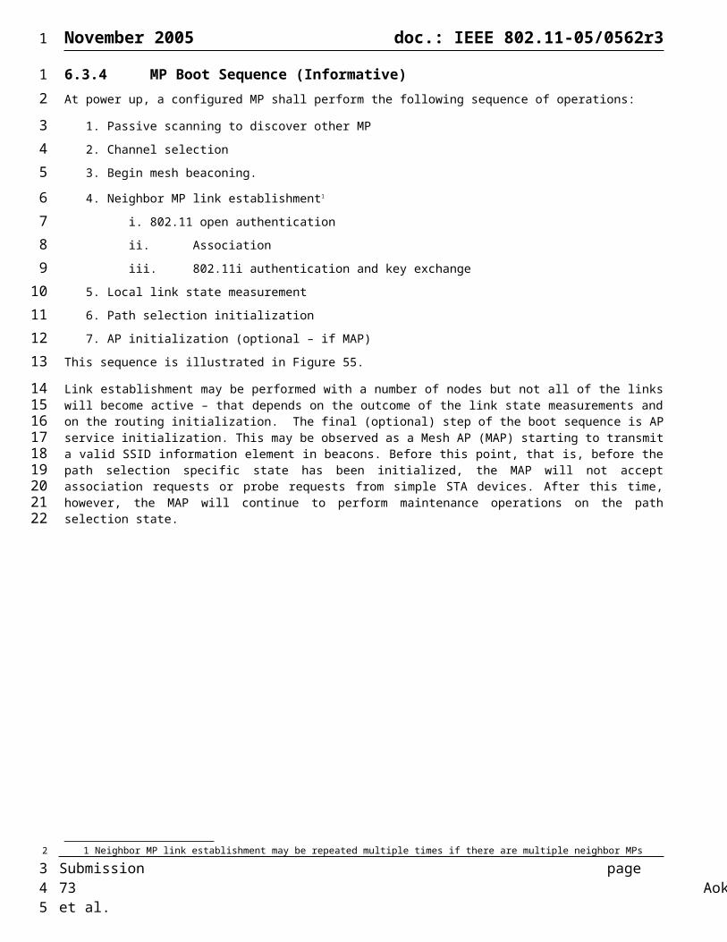
November 2005 doc.: IEEE 802.11-05/0562r3
Sender address Length Frame Sequence Number Messages
Message Header
Figure 59: RA-OLSR packet format
The sender address shall be set to the MAC address of the interface, over which the corresponding frame was sent. The length shall be the length, in bytes, of the packet; if the length is less than or equal to the size of the packet header (i.e., the packet contains no messages), the corresponding frame MUST be silently discarded.The Frame Sequence Number (FSN) MUST be incremented by one each time a new RA-OLSR frame is transmitted. "Wrap-around" is handled as described in section 6.4.3.2.15. A separate FSN is maintained for each interface such that frames transmitted over an interface are sequentially enumeratedNote that an RA-OLSR packet may contain several RA-OLSR messages to reduce related transmission overhead.
Message Format The common layout of RA-OLSR messages is as follows:
Octets: 1 1 6 1 1 2 Variable
MessageType
Vtime Originator address
Time to Live(TTL)
Hop Count Message Sequence Number (MSN)
Payload
Figure 60: RA-OLSR message format
The message type identifies the type of the received message. The list of message types is shown in Figure 61.The originator address is the MAC address of the NODE that originated the message. This may be different from the sender-address in case that multiple messages are encapsulated in one packet. TTL is the maximum number of retransmissions of a message. Before a retransmission, the TTL MUST be decremented. A message with TTL=0 or TTL=1 MUST NOT be retransmitted.The hop count is the number of hops a message has attained. Before a message is retransmitted, the Hop Count MUST be incremented by 1.The message sequence number is a sequence number, generated by the originator NODE, which ensures that each message can be uniquely identified in the network.
Message Type Description
HELLO MPR & 2-hop neighborhood signaling
TC Topology Control : Link-state advertisement
MID Multiple interface declaration
LABA Local Association Base Advertisement
LABCA Local Association Base Checksum Advertisement
ABBR Association Base Block Request
Figure 61: Message types
Packet Processing and Message FloodingUpon receiving a management frame for routing, a node examines each of the included messages. Based on the value of the "Message Type,” the node can determine the further processing of the message.
To ensure that each message is processed by a NODE only once, each NODE maintains a Duplicate Set. In this set, the NODE records information about the most recently received messages where duplicate processing of a message is to be avoided. For such a message, a node records a "Duplicate Tuple"
Submission page 73 Aoki, et al.
1
1
23456789
101112
13
14151617181920212223
24
25
2627282930313233
2
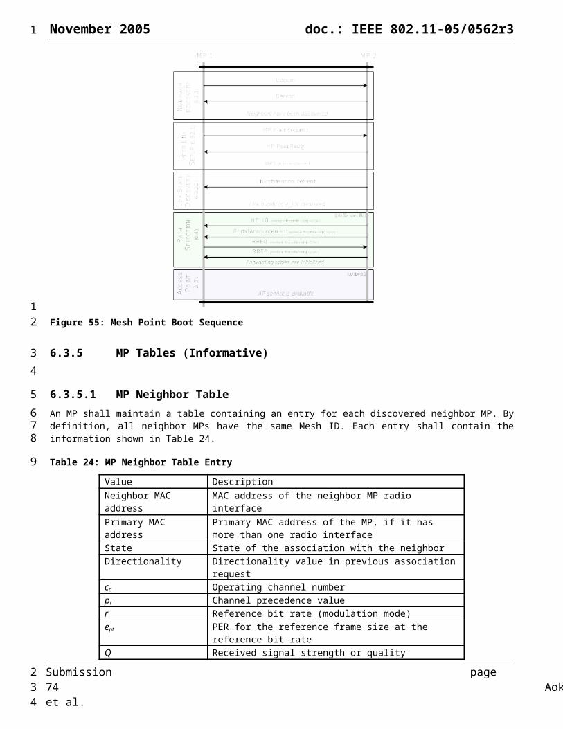
November 2005 doc.: IEEE 802.11-05/0562r3
(D_addr, D_seq_num, D_retransmitted, D_iface_list, D_time)
Field DescriptionD_addr The originator of the message
D_seq_num The message sequence number
D_retransmitted A boolean, indicating if the message is already retransmitted
D_iface_list List of the interfaces over which the message has been received
D_time Expiration time of the tuple
In a node, the set of Duplicate Tuples are denoted the "Duplicate set.”
Thus, upon receiving a basic RA-OLSR routing packet, a NODE MUST perform the following tasks for each encapsulated message:
1. If the RA-OLSR routing packet contains no messages (i.e., the packet length is less than or equal to the size of the packet header), the packet MUST be silently discarded.
2. If the TTL of the message is less than or equal to '0' (zero), or if the message was sent by the receiving node (i.e., the Originator Address of the message is the main address of the receiving node), then the message MUST be silently dropped.
3. Processing condition:a) If there exists a tuple in the duplicate set, where:
D_addr == Originator Address, AND D_seq_num == Message Sequence Numberthen the message has already been completely processed and MUST not be processed again.
b) Otherwise, if the node implements the Message Type of the message, the message MUST be processed according to the specifications for the message type.
4. Forwarding condition:a) if there exists a tuple in the duplicate set, where:
D_addr == Originator Address, AND D_seq_num == Message Sequence Number, AND the receiving interface (address) is in D_iface_listthen the message already been considered for forwarding and SHOULD NOT be retransmitted again.
b) Otherwise:i. If the node implements the Message Type of the message, the message MUST be considered for
forwarding according to the specifications for the message type.ii. Otherwise, if the node does not implement the Message Type of the message, the message SHOULD be
processed according to the default forwarding algorithm described below.
Default Forwarding AlgorithmThe default forwarding algorithm is the following:
1. If the sender interface MAC address of the message is not detected to be in the symmetric 1-hop neighborhood of the node, the forwarding algorithm MUST silently stop here (and the message MUST NOT be forwarded).
2. If there exists a tuple in the duplicate set where:D_addr == Originator MAC Address, ANDD_seq_num == Message Sequence Number
Then the message will be further considered for forwarding if and only if:D_retransmitted is false, ANDthe (address of the) interface which received the message is not included among the addresses in D_iface_list.
3. Otherwise, if such an entry doesn't exist, the message is further considered for forwarding.If after those steps, the message is not considered for forwarding, then the processing of this section stops(i.e., steps 4 to 8 are ignored).Otherwise, if it is still considered for forwarding, then the following algorithm is used:
Submission page 74 Aoki, et al.
1
12
3456789
1011121314151617181920212223242526272829303132
333435363738394041424344454647
2

November 2005 doc.: IEEE 802.11-05/0562r3
4. If the sender interface MAC address is an interface MAC address of an MPR selector of this node and if the TTL of the message is greater than '1', the message MUST be retransmitted (as described later in steps 6 to 8).
5. If an entry in the duplicate set exists, with same Originator MP Address, and same Message Sequence Number, the entry is updated as follows:
D_time = current time + DUP_HOLD_TIME.The receiving interface MAC address is added to D_iface_list.D_retransmitted is set to true if and only if the message will be retransmitted according to step 4.
Otherwise an entry in the duplicate set is recorded with:D_addr = Originator MAC AddressD_seq_num = Message Sequence NumberD_time = current time + DUP_HOLD_TIME.D_iface_list contains the receiving interface address.D_retransmitted is set to true if and only if the message will be retransmitted according to step 4.
If, and only if, according to step 4, the message must be retransmitted then:6. The TTL of the message is decremented by one.7. The hop-count of the message is increased by one8. The message is broadcast on all interfaces
Considerations on Processing and ForwardingIt should be noted that the processing and the forwarding of messages are two different actions, conditioned by different rules. Processing relates to using the content of the messages, while forwarding is related to retransmitting the same message for other nodes of the network.
Notice that this specification includes a description for both the forwarding and the processing of each known message type. Messages with known message types MUST *NOT* be forwarded "blindly" by this algorithm. Forwarding (and setting the correct message header in the forwarded, known message) is the responsibility of the algorithm specifying how the message is to be handled and, if necessary, retransmitted. This enables a message type to be specified such that the message can be modified while in transit (e.g., to reflect the route the message has taken). It also enables bypassing of the MPR flooding mechanism if for some reason classical flooding of a message type is required, the algorithm which specifies how such messages should be handled will simply rebroadcast the message, regardless of MPRs.
By defining a set of message types, which MUST be recognized by all implementations of RA-OLSR, it will be possible to extend the protocol through introduction of additional message types, while still being able to maintain compatibility with older implementations.
Message Emission and JitterAs a basic implementation requirement, the synchronization of control messages SHOULD be avoided. As a consequence, RA-OLSR control messages SHOULD be emitted such that they avoid synchronization.Emission of control traffic from neighbor nodes may, for various reasons (mainly timer interactions with packet processing), become synchronized such that several neighbor nodes attempt to transmit control traffic simultaneously. This may lead to collisions and hence message loss - possibly loss of several subsequent messages of the same type.To avoid such synchronizations, the following simple strategy for emitting control messages is proposed. A node SHOULD add an amount of jitter to the interval at which messages are generated. The jitter must be a random value for each message generated. Thus, for a node utilizing jitter:
Actual message interval = MESSAGE_INTERVAL - jitter
Where jitter is a value, randomly selected from the interval [0, MAXJITTER] and MESSAGE_INTERVAL is the value of the message interval specified for the message being emitted (e.g., HELLO_INTERVAL for HELLO messages, TC_INTERVAL for TC-messages etc.).Jitter SHOULD also be introduced when forwarding messages. The following simple strategy may be adopted: when a message is to be forwarded by a node, it should be kept in the node during a short period of time:
Keep message period = jitter
Submission page 75 Aoki, et al.
1
123456789
101112131415161718
1920212223242526272829303132333435
3637383940414243444546474849505152535455
2
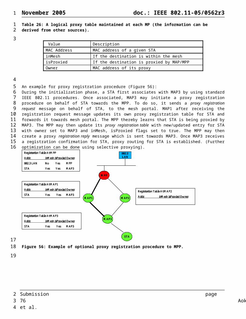
November 2005 doc.: IEEE 802.11-05/0562r3
Where jitter is a random value in [0, MAXJITTER]. Notice that when the node sends a control message, the opportunity to piggyback other messages (before their keeping period is expired) maybe taken to reduce the number of packet transmissions.
6.4.3.2.4 Information RepositoriesThrough the exchange of RA-OLSR control messages, each node accumulates information about the network. This information is stored according to the descriptions in this section.
Link SetA node records a set of “link tuples”:
(L_local_iface_addr, L_neighb_iface_addr, L_time)describing links between local and remote interfaces. The tuples in this set are maintained by some other component of 802.11 and populated using Neighbor Table Entry whose state is subordinate link up or Superordinate, link up as described in section 6.3.5.1.
Field Description
L_local_iface_addr The interface on the local MP
L_neighb_iface_addr The interface on the remote MP, with which there exists a symmetric link
L_time The expiration time of this tuple
L_link_metric The value representing link quality. An example is the Airtime cost given in section 6.4.2.1
Neighbor SetAn MP records a set of "neighbor tuples":
(N_neighbor_main_addr, N_willingness)describing neighbors.
Field DescriptionN_neighb_main_addr The interface on the local MP
N_willingness An integer, between 0 and 7, specifying the nodes willingness to carry traffic on behalf of other MPs
Interface Association SetFor each destination in the network, "Interface Association Tuples" are recorded:
(I_iface_addr, I_main_addr, I_time)
Field DescriptionI_iface_addr An interface address of a node
I_main_addr The main address of a node
I_time The expiration time of the tuple
2-hop Neighbor SetA node records a set of "2-hop tuples" :
(N_neighbor_main_addr, N_2hop_addr, N_time) describing symmetric links between its neighbors and the symmetric 2-hop neighborhood.
Field Description
Submission page 76 Aoki, et al.
1
12
3456
789
10111213
14
1516171819
20
21222324
25
2627282930
2

November 2005 doc.: IEEE 802.11-05/0562r3
N_neighbor_main_addr The main address of a neighbor
N_2hop_addr The main address of a neighbor, which has a symmetric link to N_neighbor_main_addr
N_time The expiration time of the tuple
MPR SetAn MP maintains a set of neighbors which are selected as MPR. Their main addresses are listed in the MPR Set.
MPR Selector SetAn MP records a set of MPR-selector tuples:
(MS_main_addr, MS_time) describing the neighbors which have selected this MP as an MPR.
Field Description
MS_iface_addr The main address of an MPR-selector
MS_time The expiration time of the tuple
Topology SetEach node in the network maintains topology information about the network. This information is acquired from TC-messages and is used for routing table calculations. Thus, for each destination in the network, at least one "Topology Tuple":
(T_dest_addr, T_last_addr, T_seq, T_time, T_link_metric) is recorded.
Field DescriptionT_dest_addr The main address of a node, which may be reached in one hop from the
node with main address T_last_addr
T_last_addr An MP which can reach T_dest_addr in one hop
T_seq A sequence number
T_time The expiration time of the tuple
T_link_metric The value representing link quality. The highest one among links if several links exist. An example is the Airtime cost given in section 6.4.2.1.
Local Association Base (LAB)Each MAP, as a result of the 802.11 association protocol, keeps a set of associated legacy 802.11 stations, denoted Local Association Base” (LAB) in this document, which holds “Local Association Tuple”, one for each associated legacy station. Additionally, to provide support for a large number of stations, each MAP divides its LAB into blocks of local association tuples: each block is a subset of the LAB, and the LAB is the union of those subsets . The blocks of the LAB are numbered; hence each block is identified by an integer, the “block index”.Each element of the LAB, a “Local Association Tuple” of an associated station, has the following fields:
(block_index, station_address, station_sequence_number)
Field Description
block index Index of the block the “Local Association Tuple” belongs to.
Submission page 77 Aoki, et al.
1
1
234
56789
10
111213141516
17
18192021222324252627
2
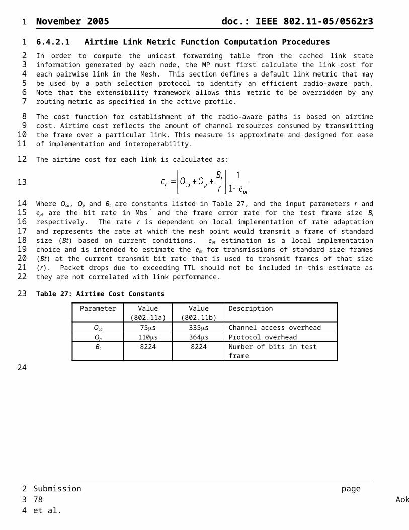
November 2005 doc.: IEEE 802.11-05/0562r3
station address The Mac address of the associated station
station_sequence_number The sequence number in the management of the frame that a station sent to the mesh AP when the station associated with or disassociated with the mesh AP
Global Association Base (GAB)Each MAP maintains information concerning which station is associated to which MAP in the entire WLAN Mesh, in a “Global Association Base” (GAB) which is union of all LAB of each MAP in the WLAN Mesh. It is a set of "global association tuples" containing
(block_index, ap_address, station_address, station_sequence_number, expiration_time)
Field Descriptionblock index Index of block associated to the station address by the MAP in its LAB.
AP_address the MAC address of the MAP
station_address The mac address of the associated station
station_sequence_number The sequence number in the management of the frame that a station sent to the MAP when the station associated with or disassociated with the MAP.
expiration_time The time at which the entry is no longer valid
6.4.3.2.5 Multiple InterfacesThe relationship between RA-OLSR interface addresses and main addresses is defined through the exchange of Multiple Interface Declaration (MID) messages. This section describes how MID messages are exchanged and processed.Each node with multiple interfaces MUST announce, periodically, information describing its interface configuration to other MPs in the network. This is accomplished through flooding a MID message to all MPs in the network.
MID Message FormatThe proposed format of a MID message is as follows
Octets: 1 1 1 6*N
Message Type:MID
Vimte TTL RA-OLSR interface Address
The ID shall be set to MID type constant (TBD)The vtime shall be set to constant MID_HOLD_TIMETTL shall be set to 255. The RA-OLSR Interface Address field shall be the address of a RA-OLSR interface of the MP, excluding the MPs main address (which already indicated in the originator address). All interface addresses other than the main address of the originator MP are put in the MID message. If the maximum allowed message size (as imposed by the network) is reached while there are still interface addresses which have not been inserted into the MIDmessage, more MID messages are generated until the entire interface addresses set has been sent.
MID Message GenerationA MID message is sent by an MP in the network to declare its multiple interfaces (if any). I.e., the MID message contains the list of interface addresses which are associated to its main address. The list of addresses can be partial in each MID message (e.g., due to message size limitations, imposed by the network), but parsing of all MID messages describing the interface set from an MP MUST be complete within a certain refreshing period (MID_INTERVAL). The information
Submission page 78 Aoki, et al.
1
1
234567
8
910111213
14151617
181920212223242526
2728293031
2

November 2005 doc.: IEEE 802.11-05/0562r3
diffused in the network by these MID messages will help each MP to calculate its routing table. An MP which has only a single interface address participating in the MANET (i.e., running RA-OLSR), MUST NOT generate any MID message.A node with several interfaces, where more than one is participating in the WLAN Mesh and running RA-OLSR MUST generate MID messages as specified.
MID Message ForwardingMID messages are broadcast and retransmitted by the MPRs in order to diffuse the messages in the entire network. The "default forwarding algorithm" MUST be used for forwarding of MID messages.
MID Message ProcessingThe tuples in the multiple interface association set are recorded with the information that is exchanged through MID messages.
Upon receiving a MID message, the "validity time" MUST be computed from the Vtime field of the message header (as described in section 6.4.3.2.3). Then the Multiple Interface Association Information Base SHOULD be updated as follows:
1. If the sender interface (NB: not originator) of this message is not in the symmetric 1-hop neighborhood of this MP, the message MUST be discarded.
2. For each interface address listed in the MID message:2.1 If there exist some tuple in the interface association set where:
I_iface_addr == interface address, ANDI_main_addr == originator address,
then the holding time of that tuple is set to:I_time = current time + validity time.
2.2 Otherwise, a new tuple is recorded in the interface association set where:I_iface_addr = interface address,I_main_addr = originator address,I_time = current time + validity time.
Mapping Interface Addresses and MP AddressesIn networks with multiple interface MPs operating within a common RA-OLSR area, it is required to be able to map any interface address to the corresponding main address.
Given an interface address:1. if there exists some tuple in the interface association set where:
I_iface_addr == interface addressthen the result of the main address search is the originator address I_main_addr of the tuple.
2. Otherwise, the result of the main address search is the interface address itself.
6.4.3.2.6 HELLO Message Format and GenerationHELLO messages are exchanged between neighbor MPs, and serve the purpose of populating the 2-hop neighbor set as well as carry MPR signaling.
HELLO Message Format
Octets: 1 1 1 variable
Message Type: HELLO
Htime Willingness A list of Neighbor interface info
The ID shall be set to HELLO type constant
Submission page 79 Aoki, et al.
1
1234
567
89
101112131415161718192021222324252627
28293031323334353637
38394041
4243
4445
2
November 2005 doc.: IEEE 802.11-05/0562r3
The Htime shall be an 8-bit field representing the HELLO emission interval used. The 4 highest bit of the Htime field represent the mantissa (a) and the four lowest bits the exponent (b), yielding that the HELLO interval is expressed thus:
C*(1+a/16)*2^b [in seconds]
The willingness shall be Degree of willingness to be selected as MPR. By default, an MP should advertise WILL_DEFAULTneighb_if_address shall be The address of the interface of a neighbor node. For each neighbor interface, neighbor_if_address signals if the node to which the interface address belongs is selected as MPR:The neighber interface info stores neighbor list and link status with them. Example of neighbor interface info is Table 28.
Table 28: Neighbor Interface Info
Field Value/description
Link Code Link State.see 6.3.1 One additional link statue : MPR_NEIGH - indicating that the neighbors have at least one symmetrical link AND have been selected as MPR by the sender.
Link Message Size Information about the link between the interface of the sender and the following list of neighbor interfaces. It also specifies information about the status of the neighbor.
Neighbor Interface Address 1 The MAC address of interface of neighbor node
Link Metric 1 An example is the Airtime cost in section 6.4.2.1.
………………
Neighbor Interface Address n The MAC address of interface of neighbor node
Link Metric n An example is the Airtime cost in section 6.4.2.1.
HELLO Message Generation, Forwarding & Processing
HELLO Message GenerationThis involves transmitting the Neighbor Set and the MPR Set. These are transmitted periodically, and are scoped for the node’s neighborhood only (TTL=1). The lists of addresses declared in a HELLO message is a list of neighbor interface addresses computed as follows: For each non-expired tuple in the Link Set, where L_local_iface_addr is the interface where the HELLO is to be transmitted, L_neighb_iface_addr is advertised. If the MP, to which L_neighb_iface_addr is associated is selected as MPR (i.e. a corresponding tuple exists in the MPR-set), a neighbor-tlv with type = MPR is associated with this address. The originator address for a HELLO message is set to the main address of the MP, generating the HELLO message.
HELLO Message ForwardingEach HELLO message generated is broadcast by the node on one interface to its neighbors (i.e. the interface for which the HELLO was generated). HELLO messages SHALL not be forwarded.
HELLO Message ProcessingAn MP processes incoming HELLO messages for the purpose of conducting link sensing (detailed in section Error: Reference source not found), neighbor detection and MPR selector set population (detailed in section 6.4.3.2.10). Only messages from subordinate and superordinate links (as described in section 6.3.5.1) are accepted
6.4.3.2.7 Populating the Neighbor SetAn MP maintains a set of neighbor tuples, based on the link tuples. This information is updated according to changes in the Link Set.
Submission page 80 Aoki, et al.
1
12
3
4567
8
9
10
11121314151617
181920
21222324
252627
2

November 2005 doc.: IEEE 802.11-05/0562r3
The Link Set keeps the information about the links, while the Neighbor Set keeps the information about the neighbors. There is a clear association between those two sets, since an MP is a neighbor of another MP if and only if there is at least one link between the two MPs. Only messages from subordinate and superordinate link (as described in 6.3.5.1) are accepted
In any case, the formal correspondence between links and neighbors is defined as follows:The "associated neighbor tuple" of a link tuple, is, if it exists, the neighbor tuple where:
N_neighbor_main_addr == main address of L_neighb_iface_addrThe "associated link tuples" of a neighbor tuple, are all the link tuples, where:
N_neighbor_main_addr == main address of L_neighbor_iface_addr
The Neighbor Set MUST be populated by maintaining the proper correspondence between link tuples and associated neighbor tuples, as follows:
CreationEach time a link appears, that is, each time a link tuple is created, the associated neighbor tuple MUST be created, if it doesn't already exist, with the following values:
N_neighbor_main_addr = main address of L_neighbor_iface_addr (from the link tuple)RemovalEach time a link is deleted, that is, each time a link tuple is removed, the associated neighbor tuple MUST be removed if it has no longer any associated link tuples.
These rules ensure that there is exactly one associated neighbor tuple for a link tuple, and that every neighbor tuple has at least one associated link tuple.
HELLO Message ProcessingThe "Originator Address" of a HELLO message is the main address of the MP, which has emitted the message. Likewise, the "willingness" MUST be computed from the Willingness field of the HELLO message (see section 6.4.3.2.6).
Upon receiving a HELLO message, an MP SHOULD update its Neighbor Set as follows:if the Originator Address is the N_neighbor_main_addr from a neighbor tuple included in the Neighbor Set:
then, the neighbor tuple SHOULD be updated as follows:N_willingness = willingness from the HELLO message
6.4.3.2.8 Populating the 2-hop Neighbor SetThe 2-hop neighbor set describes the set of MPs which have a symmetric link to a symmetric neighbor. This information set is maintained through periodic exchange of HELLO messages as described in this section.
HELLO Message ProcessingThe "Originator Address" of a HELLO message is the main address of the MP, which has emitted the message.Upon receiving a HELLO message, an MP SHOULD update its 2-hop Neighbor Set. Notice that a HELLO message MUST neither be forwarded nor be recorded in the duplicate set.Upon receiving a HELLO message, the "validity time" MUST be computed from the Vtime field of the message header (see section 6.4.3.2.3).The 2-hop Neighbor Set SHOULD be updated as follows:
1. For each address (henceforth: 2-hop neighbor address), listed in the HELLO:1.1 if the main address of the 2-hop neighbor address = main address of the receiving MP:
silently discard the 2-hop neighbor address. (in other words: an MP is not its own 2-hop neighbor).
1.2 Otherwise, a 2-hop tuple is created with:N_neighbor_main_addr = Originator Address;N_2hop_addr = main address of the 2-hop neighbor;N_time = current time + validity time.
Submission page 81 Aoki, et al.
1
123456789
10111213141516171819202122232425
262728293031323334
35363738
39404142434445464748495051525354
2
November 2005 doc.: IEEE 802.11-05/0562r3
This tuple may replace an older similar tuple with same N_neighbor_main_addr and N_2hop_addr values.
6.4.3.2.9 Populating the MPR setMPRs are used to flood control messages from an MP into the network while reducing the number of retransmissions that will occur in a region. Thus, the concept of MPR is an optimization of a classical flooding mechanism.Each MP in the network selects, independently, its own set of MPRs among its 1-hop neighborhood. The neighbor interfaces, which are selected as MPR, are advertised with an associated neighbor-tlv with type=MPR in HELLO messages.The MPR set MUST be calculated by an MP in such a way that it, through the neighbors in the MPR-set, can reach all strict 2-hop neighbors with minimum radio-aware metric. (Notice that an MP, a, which is a direct neighbor of another MP, b, is not also a strict 2-hop neighbor of MP b). This means that the union of the symmetric 1-hop neighborhoods of the MPR MPs contains the strict 2-hop neighborhood. MPR set recalculation should occur when changes are detected in the symmetric neighborhood or in the symmetric strict 2-hop neighborhood. MPR set recalculation should also occur when the change of a radio-aware metric is larger than a defined threshold.MPRs are computed per interface, the union of the MPR sets of each interface make up the MPR set for the MP.While it is not essential that the MPR set is minimal, it is essential that all strict 2-hop neighbors can be reached through the selected MPR MPs. An MP SHOULD select an MPR set such that any strict 2-hop neighbor is covered by at least one MPR MP. Keeping the MPR set small ensures that the overhead of the protocol is kept at a minimum.The MPR set can coincide with the entire neighbor set. This could be the case at network initialization (and will correspond to classic link-state routing).The heuristic for the selection of MPRs in the original OLSR does not take into account the radio-aware metric. It computes an MPR set with minimal cardinality and therefore links with lower radio-aware metric can be omitted. Consequently, the path calculated between two nodes using the known partial topology is not optimal (in terms of radio-aware metric) in the whole network.The decision of how each node selects its MPRs is essential to determinate the optimal radio-aware metric path in the network. In the MPR selection, links with low radio-aware metric SHOULD not be omitted.
MPR ComputationThe following specifies a proposed heuristic for selection of MPRs. It constructs an MPR-set that enables an MP to reach any MP in the strict 2-hop neighborhood through relaying by one MPR with willingness different from WILL_NEVER. The heuristic MUST be applied per interface: The MPR set for an MP is the union of the MPR sets found for each interface. The following terminology will be used in describing the heuristics:
Terminology Descriptionneighbor of an interface an MP is a "neighbor of an interface" if the interface (on the local MP) has a link to any one interface
of the neighbor MP.
2-hop neighbors reachable from an interface
the list of 2-hop neighbors of the MP that can be reached from neighbors of this interface
MPR set of an interface a (sub)set of the neighbors of an interface with a willingness different from WILL_NEVER, selected such that through these selected MPs, all strict 2-hop neighbors reachable from that interface are reachable
N N is the subset of neighbors of the MP, which are neighbor of the interface I.
N2 The set of 2-hop neighbors reachable from the interface I, excluding:(i) the MPs only reachable by members of N with willingness WILL_NEVER(ii) the MP performing the computationiii) all the neighbors: the MPs for which there exists a link to this MP on some interface
D(y) The degree of a 1-hop neighbor MP y (where y is a member of N), is defined as the number of symmetric neighbors of MP y, EXCLUDING all the members of N and EXCLUDING the MP performing the computation
The proposed heuristic is as follows:
Submission page 82 Aoki, et al.
1
1
2
3456789
1011121314151617181920212223242526
272829303132
3334
2
November 2005 doc.: IEEE 802.11-05/0562r3
1. Start with an MPR set made of all members of N with N_willingness equal to WILL_ALWAYS2. Calculate D(y), where y is a member of N, for all MPs in N.3 Add to the MPR set those MPs in N, which are the *only* MPs to provide reachability to an MP in N2. For example,
if MP b in N2 can be reached only through a symmetric link to MP a in N, then add MP a to the MPR set. Remove the MPs from N2 which are now covered by an MP in the MPR set.
4. While there exist MPs in N2 which are not covered by at least one MP in the MPR set:4.1 For each MP in N, calculate the reachability, i.e., the number of MPs in N2 which are not yet covered by at
least one MP in the MPR set, and which are reachable through this 1-hop neighbor;4.2 Select as an MPR the MP with the highest N_willingness among the MPs in N with non-zero reachability.
In case of multiple choices, we use tie-breakers in the following order:- Minimum radio-aware metric;- Maximum reachability (i.e., reachability to the maximum number of MPs in N2);- Maximum degree (D(.))Remove the MPs from N2 which are now covered by an MP in the MPR set.
5. An MP's MPR set is generated from the union of the MPR sets for each interface. As an optimization, process each MP, y, in the MPR set in increasing order of N_willingness. If all MPs in N2 are still covered by at least one MP in the MPR set excluding MP y, and if N_willingness of MP y is smaller than WILL_ALWAYS, then MP y MAY be removed from the MPR set.
Other algorithms, as well as improvements over this algorithm, are possible. For example, assume that in a multiple-interface scenario there exists more than one link between MPs 'a' and 'b'. If MP 'a' has selected MP 'b' as MPR for one of its interfaces, then MP 'b' can be selected as MPR without additional performance loss by any other interfaces on MP 'a'.
6.4.3.2.10 Populating the MPR Selector SetThe MPR selector set of an MP, n, is populated by the main addresses of the MPs which have selected n as MPR. MPR selection is signaled through HELLO messages.
HELLO Message ProcessingUpon receiving a HELLO message, if an MP finds one of its own interface addresses in the list with a Neighbor Type equal to MPR_NEIGH, information from the HELLO message must be recorded in the MPR Selector Set.
The "validity time" MUST be computed from the Vtime field of the message header (see section 6.4.3.2.3). The MPR Selector Set SHOULD then be updated as follows:
1. If there exists no MPR selector tuple with:MS_main_addr == Originator Address
then a new tuple is created with:MS_main_addr = Originator Address
2. The tuple (new or otherwise) withMS_main_addr == Originator Address
is then modified as follows:MS_time = current time + validity time.
Deletion of MPR selector tuples occurs in case of expiration of the timer or in case of link breakage as described in the "Neighborhood and 2-hop Neighborhood Changes".
Neighborhood and 2-hop Neighborhood ChangesA change in the neighborhood is detected when:- The L_SYM_time field of a link tuple expires. This is considered as a neighbor loss if the link described by the expired tuple was the last link with a neighbor MP (on the contrary, a link with an interface may break while a link with another interface of the neighbor MP remains without being observed as a neighborhood change).- A new link tuple is inserted in the Link Set with a non expired L_SYM_time or a tuple with expired L_SYM_time is modified so that L_SYM_time becomes non-expired. This is considered as a neighbor appearance if there was previously no link tuple describing a link with the corresponding neighbor MP.
Submission page 83 Aoki, et al.
1
123456789
10111213141516171819202122
23242526
27282930313233343536373839404142434445
464748495051525354
2
November 2005 doc.: IEEE 802.11-05/0562r3
A change in the 2-hop neighborhood is detected when a 2-hop neighbor tuple expires or is deleted according to section 6.4.3.2.8.
The following processing occurs when changes in the neighborhood or the 2-hop neighborhood are detected:- In case of neighbor loss, all 2-hop tuples with N_neighbor_main_addr == Main Address of the neighbor MUST be deleted.- In case of neighbor loss, all MPR selector tuples with MS_main_addr == Main Address of the neighbor MUST be deleted- The MPR set MUST be re-calculated when a neighbor appearance or loss is detected, or when a change in the 2-hop neighborhood is detected.- An additional HELLO message MAY be sent when the MPR set changes.
6.4.3.2.11 Topology DiscoveryThe link sensing and neighbor detection part of the protocol basically offers, to each MP, a list of neighbors with which it can communicate directly and, in combination with the Packet Format and Forwarding part, an optimized flooding mechanism through MPRs. Based on this, topology information is disseminated through the network. The present section describes which part of the information given by the link sensing and neighbor detection is disseminated to the entire network and how it is used to construct routes.
Routes are constructed through advertised links and links with neighbors. An MP must at least disseminate links between itself and the MPs in its MPR-selector set, in order to provide sufficient information to enable routing.
TC Message FormatThe proposed format of a TC message is as follows:
2 N*(6+M)
ANSN A list of Advertised Neighbor Main Addresses with their link metric
Advertised Neighbor Sequence Number (ANSN) shall be a sequence number which is associated with the advertised neighbor set. Every time an MP detects a change in its advertised neighbor set, it increments this sequence number ("Wraparound" is handled as described in section 6.4.3.2.15). This number is sent in this ANSN field of the TC message to keep track of the most recent information. When an MP receives a TC message, it can decide on the basis of this advertised Neighbor Sequence Number, whether or not the received information about the advertised neighbors of the originator MP is more recent than what it already has.
Advertised Neighbor Main Address shall be the field which contains the main address of a neighbor MP. All main addresses of the advertised neighbors of the Originator MP are put in the TC message. If the maximum allowed message size (as imposed by the network) is reached while there are still advertised neighbor addresses which have not been inserted into the TC-message, more TC messages will be generated until the entire advertised neighbor set has been sent. Extra main addresses of neighbor MPs may be included, if redundancy is desired. Advertisement Neighbor Main address pairs with its link metric. If two nodes are connected through several links, a node selects the highest vale among them and advertise it.
Advertised Neighbor SetA TC message is sent by an MP in the network to declare a set of links, called advertised link set which MUST include at
least the links to all MPs of its MPR Selector set, i.e., the neighbors which have selected the sender MP as an MPR.The sequence number (ANSN) associated with the advertised neighbor set is also sent with the list. The ANSN number
MUST be incremented when links are removed from the advertised neighbor set; the ANSN number SHOULD be incremented when links are added to the advertised neighbor set.
TC Message Generation
Submission page 84 Aoki, et al.
1
123456789
1011
12131415161718192021
222324
25262728293031323334353637383940
41424344454647
48
2

November 2005 doc.: IEEE 802.11-05/0562r3
In order to build the topology information base, each MP, which has been selected as MPR, broadcasts Topology Control (TC) messages. TC messages are flooded to all MPs in the network and take advantage of MPRs. MPRs enable a better scalability in the distribution of topology information [14].
The list of addresses can be partial in each TC message (e.g., due to message size limitations, imposed by the network), but parsing of al TC messages describing the advertised link set of an MP MUST be complete within a certain refreshing period (TC_INTERVAL). The information diffused in the network by these TC messages will help each MP calculate its routing table.
When the advertised link set of an MP becomes empty, this MP SHOULD still send (empty) TC-messages during the duration equal to the "validity time" (typically, this will be equal to TOP_HOLD_TIME) of its previously emitted TC-messages, in order to invalidate the previous TC-messages. It SHOULD then stop sending TC-messages until some MP is inserted in its advertised link set.
An MP MAY transmit additional TC-messages to increase its reactiveness to link failures. When a change to the MPR selector set is detected and this change can be attributed to a link failure, a TC-message SHOULD be transmitted after an interval shorter than TC_INTERVAL.
In order to realize the frequency control, when a node initiates a TC message, RA-OLSR will set different maximum hop count value for the packet according to the different frequencies. With the different maximum hop count values, the packets can only reach different designed scopes. The maximum hop limit is equal to the TTL value of an IP packet. Since the original OLSR TC packet has defined this parameter “Hop Count”, we then simple use to realize the different frequencies. The TTL of the TC massage is set to 2, 4 and mac TTL value every 3*TC_INTERVAL.
TC Message ForwardingTC messages are broadcast and retransmitted by the MPRs in order to diffuse the messages in the entire network. TC messages MUST be forwarded according to the "default forwarding algorithm" (described in section 6.4.3.2.3).
TC Message ProcessingUpon receiving a TC message, the "validity time" MUST be computed from the Vtime field of the message header (see section 6.4.3.2.3). The topology set SHOULD then be updated as follows (using section 6.4.3.2.15 for comparison of ANSN):
1. If the sender interface (NB: not originator) of this message is not in the symmetric 1-hop neighborhood of this MP, the message MUST be discarded.
2. If there exist some tuple in the topology set where:T_last_addr == originator address ANDT_seq > ANSN,
then further processing of this TC message MUST NOT be performed and the message MUST be silently discarded (case: message received out of order).
3. All tuples in the topology set where: T_last_addr == originator address AND T_seq < ANSN
MUST be removed from the topology set.4. For each of the advertised neighbor main address received in the TC message:
4.1 If there exist some tuple in the topology set where:T_dest_addr == advertised neighbor main address, ANDT_last_addr == originator address,
then the holding time of that tuple MUST be set to:T_time = current time + validity time.
4.2 Otherwise, a new tuple MUST be recorded in the topology set where:T_dest_addr = advertised neighbor main address,T_last_addr = originator address,T_seq = ANSN,T_time = current time + validity time
6.4.3.2.12 Routing Table Calculation
Submission page 85 Aoki, et al.
1
123456789
1011121314151617181920
21222324
25262728293031323334353637383940414243444546474849505152
53
2
November 2005 doc.: IEEE 802.11-05/0562r3
Each MP maintains a routing table which allows it to route data destined for the other MPs in the network. The routing table is based on the information contained in the local link information base and the topology set. Therefore, if any of these sets are changed, the routing table is recalculated to update the route information about each destination in the network. The route entries are recorded in the routing table in the following format:
1. R_dest_addr R_next_addr R_dist R_metric R_iface_addr2. R_dest_addr R_next_addr R_dist R_metric R_iface_addr3. ,, ,, ,, ,, ,,
Each entry in the table consists of R_dest_addr, R_next_addr, R_dist, R_metric and R_iface_addr. Such entry specifies that the MP identified by R_dest_addr is estimated to be R_dist hops away from the local MP with the cumulative radio-aware metric equal to R_metric, that the symmetric neighbor MP with interface address R_next_addr is the next hop MP in the route to R_dest_addr, and that this symmetric neighbor MP is reachable through the local interface with the address R_iface_addr. Entries are recorded in the routing table for each destination in the network for which a route is known. All the destinations, for which a route is broken or only partially known, are not recorded in the table.
More precisely, the routing table is updated when a change is detected in either:
- the link set,- the neighbor set,- the 2-hop neighbor set,- the topology set,- the Multiple Interface Association Information Base,
More precisely, the routing table is recalculated in case of neighbor appearance or loss, when a 2-hop tuple is created or removed, when a topology tuple is created or removed or when multiple interface association information changes. The update of this routing information does not generate or trigger any messages to be transmitted, neither in the network, nor in the 1-hop neighborhood.
Route SelectionTo construct the routing table of MP X, a shortest path algorithm is run on the directed graph containing the arcs X -> Y where Y is any symmetric neighbor of X (with Neighbor Type equal to SYM), the arcs Y -> Z where Y is a neighbor MP with willingness different of WILL_NEVER and there exists an entry in the 2-hop Neighbor set with Y as N_neighbor_main_addr and Z as N_2hop_addr, and the arcs U -> V, where there exists an entry in the topology set with V as T_dest_addr and U as T_last_addr.
The optimal path will be selected through the following procedure using the neighbor set, the link set, the 2-hop neighbor set and the topology set:
1. All the entries from the routing table are removed. Clear the list of candidate mesh points. Initialize the shortest-path tree to only the root.
2. Call the mesh point just added to the tree mesh point V. For each mesh point W which is the one-hop neighbor and the link between V and W is the SYM link, Calculate the link cost (the sum of radio-aware metric sum) D of the resulting path from the root to W. D is equal to the sum of the link cost of the (already calculated) shortest path to vertex V and the advertised cost of the link between vertices V and W. If D is:
Greater than or equal to the value that already appears for vertex W on the candidate list, then examine the next mesh point.
Less than the value that appears for W on the candidate list, or if W does not yet appear on the candidate list, then set the entry for W on the candidate list to indicate D from the root. The next hop that result from the candidate path for W accordingly is set to the same as the next hop of V.
3. If at this step the candidate list is empty, the shortest-path tree (of transit vertices) has been completely built and the algorithm terminates. Otherwise, choose the mesh point belonging to the candidate list that is closest to the root, and add it to the shortest-path tree (removing it from the candidate list in the process).
4. The new route entries for the destination MP W is recorded in the routing table.5. Iterate the algorithm by returning to Step 2.
Submission page 86 Aoki, et al.
1
123456789
101112131415161718192021222324252627282930313233343536373839404142434445464748495051525354555657
2
November 2005 doc.: IEEE 802.11-05/0562r3
6.4.3.2.13 Associated Station Discovery
Message Format
Local Association Base Advertisement (LABA)The LABA message format is shown as follows:
6 2 Variables
Originator Mesh AP MAC Address
Life time A List of block
The Originator Mesh AP MAC Address shall be MAC address of Mesh AP originating this message.The Life time shall be the time for how long the information contained in the message as valid, unless a more recent update to the information is received.Each Block shall include the list of legacy station addresses with their sequence number.
The message hence holds a list of information about blocks, identified by their block index. Each block in the message includes the list of legacy station addresses with their sequence number. These station addresses are those, in the LAB of the originator, that are in the block identified by “block index”. In the message, the “Block Message Size” is used, quite naturally, to indicate the amount of number of entries are following it, which are to be associated with “Block index”. More precisely, Block Message Size is the size of the information for the block, counted in bytes and measured from the beginning of the “Block Index” field and until the next “Block Index” field (or - if there are no more blocks – the end of the message). Note that the RA-OLSR message header holds the address of the originator Mesh AP, and the validity time (vtime field) of the information.
Table 29: A list of blocks
Field Value/description
Block 1 index Block index which stores a list of legacy 802.11 station addresses with their sequence number
Block message size The number of 802.11 stations in the block
Station Address 1 The MAC address of the associated legacy station
Station Sequence Number 1 The sequence number in association management frame sent by the station
Station Address 2 The MAC address of the associated legacy station
Station Sequence Number 2 The sequence number in association management frame sent by the station
….. …..
Block 2 index Block index which stores a list of legacy 802.11 stations with their sequence number
Block message size The number of 802.11 stations in the block
Station Address 1 The MAC address of the associated legacy station
Station Sequence Number 1 The sequence number in association management frame sent by the station
Submission page 87 Aoki, et al.
1
1
2
345
6789
1011121314151617181920
21
2223
2

November 2005 doc.: IEEE 802.11-05/0562r3
This message is the sole used in the “Full Base Diffusion” mode, the default mode, as it is sufficient for one Mesh AP to broadcast its entire Local Association Base. Note that format allows the Mesh AP to advertise only some of the blocks: for instance if the Local Association Base in too large to fit a single message.
Local Association Base Checksum Advertisement (LABCA) messageIn the optional “Checksum” mode, two additional of messages are used:- One message to advertise the checksum of the Local Association Table instead of the full Local Association Table, a
“Local Association Base Checksum Advertisement” (LABCA) message.- One message for requiring part of the Local Association Base, when a Mesh Point detects with the previous kind of
message, that its Global Information Base doesn’t include proper information: an Association Base Block Request (ABBR) message.
The proposed format of a Local Association Base Checksum Advertisement (LABCA) message is the following:
6 2 1 Variables
Originator Mesh AP MAC Address Life time # of checksums A List of checksums
for block
This message include list of checksums for all the blocks in the Local Association Base of the originator Mesh AP. The checksums are discussed in another section, but the principle is that one block is supposed different (“inconsistent”) if and only if the checksum is different.
Association Base Block Request (ABBR) MessageUpon receiving Local Association Status Advertisement, the Mesh AP compares status value of all blocks in global association based from the originator Mesh AP. If the Mesh AP finds the mismatched values, the Mesh AP unicasts a request for station information in blocks whose values mismatch to Originator Mesh AP.
The proposed format of a Association Base Block Request is the following:
6 2 Variables
Originator Mesh AP MAC Address Life time
A List of block index requested
The source and the destination addresses are the first two fields. Then a list of block indices follows, which are the blocks that the source Mesh Point has detected to be inconsistent, and for which it requires the content.
Associated Station Discovery in “Full Base Diffusion” modeAs explained previously, in “Full Base Diffusion” mode, the Mesh AP broadcasts periodically messages (LABA messages), representing the full content of its Local Association Base; the other Mesh Points receive them and populate their Global Association Table by this means.
Local Association Base Advertisement (LABA) Message GenerationA Mesh AP with associated station generates periodically LABA messages containing the pairs of (Associated Legacy Station Addresses, Station Sequence Number), with proper block index, corresponding to the currently associated legacy stations in its Local Associated Station Base. LABA messages are broadcast to the entire WLAN Mesh.The Mesh AP must generate LABA messages before the entries of the previous LABA message(s) reach their expiration time (as advertised by expire time).
Submission page 88 Aoki, et al.
1
1234
56789
1011121314
1516171819
20212223242526
2728293031
3233343536
373839404142
2
November 2005 doc.: IEEE 802.11-05/0562r3
As an optimization to increase responsiveness of the station discovery protocol to changes in the association tables, a Mesh AP may generate an earlier LABA message in case of change (which may include information for all blocks as previous LABA messages, or only the blocks that have changed).
LABA Message ForwardingLABA messages are broadcast and retransmitted by the MPRs in order to diffuse the messages to the entire network. LABA messages MUST be forwarded according to the “default forwarding algorithm” (described in section 6.4.3.2.3)
LABA Message ProcessingUpon receiving an LABA Message, each Mesh Point updates its Global Association Base and its Local Association Base, as described in the following sections.
Populating the Global Association Base PopulationHaving received an LABA Message, the receiver Mesh Point will use the following information:- the originator address in the RA-OLSR message header of the LABA message: the address of the Mesh AP which generated the message- the list of associated STAs addresses (with their sequence numbers)
It will perform the actions of:- ensuring that any new association is added to the Global Association Base- ensuring that any terminated association is removed from the Global Association Base- updating properly the expiration times of the global association tuple with the one from the message received
More precisely, it updates the Global Association Base as follows:1. Global Association Base Block cleaning for originator Mesh AP: for each advertised block, the received information
will include all the content of the block as present in the last Local Association Base (of the originator Mesh AP): all preexisting tuples are now obsolete, and hence the following step is performed:
2. The receiving Mesh Point deletes any global association tuple where GA_AP_address == LABA message originator, and where GA_block_index is one of the block indices in the LABA message.
3. Update of information for advertised associated stations:For each station entry in the list of associated STAs, potential corresponding information in the Global Association Table is added or updated:3.1 If there exists some global association tuple in global association base where:
GA_AP_address == LABA Message originator, ANDGA_station_address == station address, ANDGA_station_sequence_number <= Station sequence number of the entry
Then, it is updated as follows:GA_station_sequence_number = station sequence number in frameGA_block_index = block index GA_expiration_time = current time + validity time
3.2 Otherwise, if there exists some station tuple in the global association bases where:GA_AP_address == LABA Message originator, ANDGA_station_address == station address of the current entry, ANDGA_station_sequence_number > Station sequence number of the entry
Then, the information in the message relative to the station is ignored because it is considered obsolete3.3 Otherwise, a new station tuple is recorded in the Global Association Base where:
GA_AP_address = LABA Message originator,GA_station_address = station address of the current entryGA_block_index == block index,GA_station_sequence_number = station sequence number of the entryGA_expiration_time = current time + validity time
Populating the Local Association Base: Update
Submission page 89 Aoki, et al.
1
1234
5678
9101112
13141516171819202122232425262728293031323334353637383940414243444546474849505152
53
2
November 2005 doc.: IEEE 802.11-05/0562r3
Because a Mesh AP may not always be informed directly of a disassociation of a legacy STA, it can be the case that it detects indirectly a disassociation by discovering that another Mesh Point advertises a STA believed to be associated, and with a newer sequence number.
To handle the occurrence of such event, the following processing is done:- For each added entry in the list of associated STAs, if there exists a tuple in the Local Association Base where:
LA_station_address = associated station address of the entryLA_station_sequence_number <= station sequence number of the entry
Then the Local Association Tuple is deleted and the corresponding legacy STAs is assumed to be disassociated (and other 802.11 protocols might be informed of such an event).
Associated Station Address Search and Population of the Routing Table The intent of the maintenance of the different Association Tables is that when a Mesh Point would need a mesh path for an associated station address, it would proceeds as follows: it would search in its Local Association Base, and in its Global Association Base, for association tuples with the required address. If more than one were found to be present, the Mesh Point would choose the association tuple with the highest GA_station_sequence_number.Because the routes are proactively computed, instead of performing this search, the Mesh Point will complement the routing table calculation described in another section in an equivalent way with the following step:
For each entry in the Global Association Base where:• There is no local association tuple in the LAB, nor global association tuple in the GAB with the same
station_address, and a higher station_sequence_number, AND• There exists a recorded routing entry such that:
R_dest_addr == GA_AP_addressThen a route entry is created with:• R_dest_addr = GA_station_address• R_next_addr = R_next address (of the recorded routing entry)• R_dist = R_dist (of the recorded routing entry)• R_iface_addr = R_iface_addr (of the recorded routing entry)
Associated Station Discovery in “Checksum Diffusion” mode
OverviewBecause sending periodically the full Local Association Base can be expensive, especially in the presence of numerous Mesh APs, another mode of operation is presented here, with the following changes in the message generation and processing.• - Message Generation by a Mesh AP: rather than sending the whole Local Association Base, a checksum is
computed for each block of the Base, and the list of checksums is sent in a Local Association Base Checksum Advertisement (LABCA) message.
• - Message Processing by receiver Mesh Points: as a result, the receiver Mesh Points, can no longer populate their Global Association Table for the originator Mesh AP, naturally. But they will verify that the checksum of their Global Association Table matches instead.
• - Block Request by a receiver Mesh Point: when a checksum mismatch is detected, a receiver Mesh Point will issue an Association Base Block Request (ABBR) message, with the list of indices of mismatching blocks. It will be unicast to the Mesh AP.
• - Block Request processing: the indices of mismatching blocks are recorded, and will be advertised in the next LABA/LABCA generation.
The policy for choosing to generate LABCA messages instead of LABA messages is left as a choice to the Mesh AP, but the following is suggested:• - If there have been no changes in the Local Association Table for a duration greater than
STABLE_LOCAL_ASSOCIATION_TIME, the Mesh AP generates LABCA messages.• - If there is a change (i.e. station association or disassociation), it switches back to sending LABA.
As a side note, remark that a prerequisite for application of this mode of operation is that all Mesh Points in the WLAN Mesh support it.
Submission page 90 Aoki, et al.
1
123456789
1011
121314151617181920212223242526272829
30
313233343536373839404142434445464748495051525354
2

November 2005 doc.: IEEE 802.11-05/0562r3
Detailed Message Generation and Message Processing The processing of the LABA messages is unchanged compared to the operating mode “Full Base Diffusion”.
LABCA Message Generation, Forwarding and ProcessingThe generation of LABCA messages can replace the generation of LABA messages, and is straightforward from the LABCA message format description, and from the checksum calculation described in a following section.
The forwarding of LABCA messages is done according to the “default forwarding algorithm”
The processing of LABCA messages is also simple: as indicated, a verification of all the Checksum Status Values is performed for all blocks. In case of one mismatch or more an ABBR message is generated. However, for each block which matches, the GA_expiration_time of tuples in the matching blocks is updated, and also each entry in a block which has disappeared is deleted:1. For each tuple in the Global Association Base where:• GA_AP_address == Originator Address, AND
• GA_block_index == in the range from 0 to the number of blocks-1 in the messageThe field GA_expiration_time is updated as follows:• GA_expiration_time = current time + validity time (from message header)
2. For each tuple in the Global Association Base where:• GA_AP_address == Originator Address, AND• GA_block_index is greater than last block index in the LABCA message,
The tuple is deleted.
ABBR Message Generation, Forwarding and ProcessingAs indicated, at the receiver Mesh Point, an ABBR message is generated each time are detected by the receiver Mesh Point, for the blocks of the Global Association Base corresponding the originator Mesh AP address of the LABCA message. The ABBR message includes the list of the block indices for which there is a mismatch. It is sent to the Mesh AP originator of the mismatching LABCA message, with an RA-OLSR Message header in a RA-OLSR packet format, as a unicast packet with destination MAC address set to the address of the Mesh AP.
The ABBR message forwarding is simple: because the ABBR message is unicast, the message is forwarded in a similar way the data message are forwarded, i.e. hop by hop and using the routing table to reach the destination Mesh AP. Note however that the hop count and the TTL fields of the RA-OLSR message header may be updated at each hop.
The processing of ABBR messages at the destination Mesh AP consists in recording all the blocks indices for which there is a mismatch. At the next LABA/LABCA generation, the Mesh AP will either:• Broadcast a Full LABA message (with all Local Association Base).• Broadcast a LABA message with all the content of blocks for which there was (at least) one request, and broadcast
one LABCA message in addition.
Checksum calculationThe other sections use the fact that a checksum be calculated and verified. In this section, a proof of concept of performing such calculation is performed:• Assuming that the checksum of request for a block with a given index• All the corresponding association tuples, appropriately either in LAB or in the GAB, are retrieved.• They are converted in sequence of bytes (10): (MAC address, sequence number)• They are sorted by increasing order• They are concatenated as one sequence of bytes• The result of a hashing function such as MD5 is applied• All or part of the result of the hashing function, is used to represent the checksumNote that more efficient ways can be devised, provided that all nodes in the WLAN Mesh agree on it. Additionally reliability may be increased by introducing a sequence number of the message in the calculation of the hash.
Submission page 91 Aoki, et al.
1
123
456789
10111213141516171819202122232425
2627282930313233343536373839404142
434445464748495051525354
2
November 2005 doc.: IEEE 802.11-05/0562r3
6.4.3.2.14 Proposed Values for Constants This section list the values for the constants used in the description of the protocol.
Setting emission intervals and holding timesThe proposed constant for C is the following:
C = 1/16 seconds (equal to 0.0625 seconds)
C is a scaling factor for the "validity time" calculation ("Vtime" and "Htime" fields in message headers, see sections 6.4.3.2.3 and 6.4.3.2.6). The "validity time" advertisement is designed such that MPs in a network may have different and individually tuneable emission intervals, while still interoperates fully. For protocol functioning and interoperability to work:
- The advertised holding time MUST always be greater than the refresh interval of the advertised information. Moreover, it is recommended that the relation between the interval (from section 6.4.3.2.5), and the hold time is kept as specified in section 6.4.3.2.5, to allow for reasonable packet loss.- The constant C SHOULD be set to the suggested value. In order to achieve interoperability, C MUST be the same on all MPs.- The emission intervals, along with the advertised holding times (subject to the above constraints MAY be selected on a per MP basis.
Note that the timer resolution of a given implementation might not be sufficient to wake up the system on precise refresh times or on precise expire times: the implementation SHOULD round up the 'validity time' ("Vtime" and "Htime" of packets) to compensate for coarser timer resolution, at least in the case where "validity time" could be shorter than the sum of emission interval and maximum expected timer error.
Emission Intervals
HELLO_INTERVAL = 2 seconds REFRESH_INTERVAL = 2 seconds TC_INTERVAL = 5 seconds MID_INTERVAL = TC_INTERVAL HNA_INTERVAL = TC_INTERVAL
Holding Time
NEIGHB_HOLD_TIME = 3 x REFRESH_INTERVAL TOP_HOLD_TIME = 3 x TC_INTERVAL DUP_HOLD_TIME = 30 seconds MID_HOLD_TIME = 3 x MID_INTERVAL HNA_HOLD_TIME = 3 x HNA_INTERVAL
The Vtime in the message header (see section 6.4.3.2.3), and the Htime in the HELLO message (see section 6.4.3.2.6) are the fields which hold information about the above values in mantissa and exponent format (rounded up). In other words:
Value = C*(1+a/16)*2^b [in seconds]
where a is the integer represented by the four highest bits of the field and b the integer represented by the four lowest bits of the field.
Notice, that for the previous proposed value of C, (1/16 seconds), the values, in seconds, expressed by the formula above can be stored, without loss of precision, in binary fixed point or floating point numbers with at least 8 bits of fractional part. This corresponds with NTP time-stamps and single precision IEEE Standard 754 floating point numbers.
Submission page 92 Aoki, et al.
1
123
456789
10111213141516171819202122232425
2627282930313233
3435363738394041424344454647484950515253
2

November 2005 doc.: IEEE 802.11-05/0562r3
Given one of the above holding times, a way of computing the mantissa/exponent representation of a number T (of seconds) is the following:
Find the largest integer 'b' such that: T/C >= 2^bCompute the expression 16*(T/(C*(2^b))-1), which may not be a integer, and round it up. This results in the value for 'a'
if 'a' is equal to 16: increment 'b' by one, and set 'a' to 0now, 'a' and 'b' should be integers between 0 and 15, and the field will be a byte holding the value a*16+b
For instance, for values of 2 seconds, 6 seconds, 15 seconds, and 30 seconds respectively, a and b would be: (a=0,b=5), (a=8,b=6), (a=14,b=7) and (a=14,b=8) respectively.
Message Types
HELLO_MESSAGE = 1 TC_MESSAGE = 2 MID_MESSAGE = 3 HNA_MESSAGE = 4
Neighbor Types
NOT_NEIGH = 0 SYM_NEIGH = 1 MPR_NEIGH = 2
Willingness
WILL_NEVER = 0 WILL_LOW = 1 WILL_DEFAULT = 3 WILL_HIGH = 6 WILL_ALWAYS = 7
The willingness of an MP may be set to any integer value from 0 to 7, and specifies how willing an MP is to be forwarding traffic on behalf of other MPs. MPs will, by default, have a willingness WILL_DEFAULT. WILL_NEVER indicates an MP which does not wish to carry traffic for other MPs, for example due to resource constraints (like being low on battery). WILL_ALWAYS indicates that an MP always should be selected to carry traffic on behalf of other MPs, for example due to resource abundance (like permanent power supply, high capacity interfaces to other MPs).
An MP may dynamically change its willingness as its conditions change.
One possible application would, for example, be for an MP, connected to a permanent power supply and with fully charged batteries, to advertise a willingness of WILL_ALWAYS. Upon being disconnected from the permanent power supply (e.g., a PDA being taken out of its charging cradle), a willingness of WILL_DEFAULT is advertised. As battery capacity is drained, the willingness would be further reduced. First to the intermediate value between WILL_DEFAULT and WILL_LOW, then to WILL_LOW and finally to WILL_NEVER, when the battery capacity of the MP does no longer support carrying foreign traffic.
Misc. Constants
MAXJITTER = HELLO_INTERVAL / 4
6.4.3.2.15 Sequence Numbers
Submission page 93 Aoki, et al.
1
123456789
1011
12131415161718
192021222324
2526272829303132333435363738394041424344454647
48495051
52
2

November 2005 doc.: IEEE 802.11-05/0562r3
Sequence numbers are used in RA-OLSR with the purpose of discarding "old" information, i.e., messages received out of order. However with a limited number of bits for representing sequence numbers, wrap-around (that the sequence number is incremented from the maximum possible value to zero) will occur. To prevent this from interfering with the operation of the protocol, the following MUST be observed:
The sequence number S1 is said to be "greater than" the sequence number S2 if:
S1 > S2 AND S1 - S2 <= MAXVALUE/2 OR S2 > S1 AND S2 - S1 > MAXVALUE/2
where the term MAXVALUE designates the largest possible value for a sequence number.
Thus when comparing two messages, it is possible — even in the presence of wrap-around — to determine which message contains the most recent information.
6.4.4 Data Message Forwarding
6.4.4.1 MSDU OrderingIn a 802.11s mesh network, path selection and forwarding operations are implemented as layer-2 mechanisms. When data frames are forwarded in such a multi-hop mesh network, multipath routing (either due to load balancing or dynamic route changes) can easily result in arrival of out-of-order and duplicate frames the Destination Mesh Point. The probability of having out-of-order and duplicate frames increases as the rate of topology changes, load level variations, and/or wireless channel fluctuations increases. Note that the Sequence Control field in 802.11 Data Frame headers is meant to be used on a hop-by-hop basis to detect duplicates or missing frames at each hop and is changed by each intermediate Mesh Point. Hence, it cannot be used to detect out-of-order or duplicate frame delivery in an end-to-end fashion.
A new “Mesh E2E Sequence Number” in the Mesh Control field is added to uniquely identify the data frames sent from a given Source Mesh Point. By the pair of Source MP Address and Mesh E2E Sequence Number, the Destination Mesh Point is able to detect out-of-order and duplicate frames. Duplicate frames must be discarded, while out-of-order frames must be buffered temporarily before they can be re-ordered and delivered to LLC. The goal here is to manage the buffer in a way that strives to deliver all MAC frames in the correct order. To avoid excessive delay due to such buffering, a timer may be used locally by the Mesh Point so that it does not wait indefinitely. When the local timer expires, the Destination Mesh Point gives up waiting for the missing frames, delivers the queued frames and considers the missing frames as dropped. Note that such an end-to-end ordered delivery of unicast data frames is only guaranteed between the Source Mesh Point and the Destination Mesh Point, and it is possible that frames may arrive at an intermediate Mesh Point out of order. However, there shall be no reordering of unicast MSDUs received at the MAC service interface of any Mesh Point with the same TID value and the same Source Mesh Point.
6.4.4.2 Unicast Forwarding of Four-Address FramesOn receipt of a four address unicast data frame, the MP deciphers it and checks for authenticity. If it is not from an authentic source, the frame shall be silently discarded. If the “untrusted” bit is set in the QoS control field, and transport of untrusted traffic has not been enabled, the frame shall be discarded silently.
The MP then checks to see whether the destination address is known – if it is not a known address, the frame shall be discarded.
If the destination address corresponds to a legacy STA associated with this MP, the frame is translated to the three address format and queued for transmission to the destination.
If the destination address corresponds to a known MAC address, but not directly associated, the TTL field in the QoS control field is decremented and the frame discarded if zero has been reached. Otherwise, the frame is queued for transmission as a four address frame to the next-hop MP as determined from the Mesh forwarding table.
6.4.4.3 Unicast Forwarding of Three-Address FramesA MAP shall follow normal procedures for the forwarding of unicast three address frames received from associated STAs destined for other STAs within the BSS.
Submission page 94 Aoki, et al.
1
123456789
1011121314
15
1617181920212223
2425262728293031323334
35363738
3940
4142
434445
464748
2
November 2005 doc.: IEEE 802.11-05/0562r3
If a unicast data frame is received by an MAP from an associated and authenticated STA, and the destination address corresponds to an address in the forwarding table, the frame shall be reformatted as a four address frame and transmitted to the peer MP listed in the forwarding table as the next hop address for that destination address. The TTL field in the QoS control field shall be set to 255.
6.4.4.4 Broadcast Forwarding of Four-Address FramesOn receipt of a four address data frame with Address 1 set to the all-1s broadcast address, the MP deciphers it and checks for authenticity. If it is not from an authentic source, the frame shall be silently discarded.
The MP then checks a local broadcast message signature cache to see whether the message has previously been forwarded by this node. Together, the tuple of SA, DA, and Mesh E2E sequence number from the frame header may be used as a unique message signature for tracking messages in the signature cache. If it is already listed in the cache, the frame shall be discarded. Otherwise, a new signature for this message is added to the cache.
The MP then decrements the TTL field in the mesh control field. If the TTL value has reached zero, the message is discarded. Otherwise, the frame is queued for transmission as a four address frame to all neighboring MPs that are associated and authenticated to the MP.
If the node is a Mesh AP, it also creates a three-address broadcast frame with the same body contents as the received frame and transmits it to the STAs associated with it.
6.4.4.5 Multicast Forwarding of Four-Address FramesOn receipt of a four address multicast data frame, the same process used for broadcast forwarding of four address data frames is used for the multicast data frame.
The MP may implement multicast filtering technology to reduce multicast traffic flooding in the WLAN mesh network. This may be achieved, for example, by using the GARP Multicast Registration Protocol (GMRP) defined in IEEE802.1D. This filtering technology is beyond the scope of this proposal.
Support for special multicast capabilities is an implementation choice and requires invoking the extensibility feature of this (draft standard).
6.5 Security This proposal utilizes 802.11i-based security mechanisms to enable link security in a WLAN Mesh network. 802.11i provides link-by-link security in a WLAN Mesh network; it will be used to answer the question “who can utilize the mesh medium?” Note that while end-to-end security may be layered on top of 802.11s security, e.g. using IPsec, this is beyond the scope of the proposal.
6.5.1 Security FrameworkThe link access proposal is based on 802.11i RSNA security and supports both centralized and distributed IEEE 802.1X-based authentication and key management.
In a WLAN Mesh, an MP performs both the Supplicant and the Authenticator roles, and may optionally perform the role of an Authentication Server (AS). The AS may be collocated with an MP (Figure 62) or be located in a remote entity to which the MP has a secure connection (Figure 63). The establishment of a secure end-to-end connection between the MP and AS is beyond the scope of this proposal.
Submission page 95 Aoki, et al.
1
1234
567
89
1011
121314
1516
171819
202122
2324
2526272829
303132
33343536
37
2
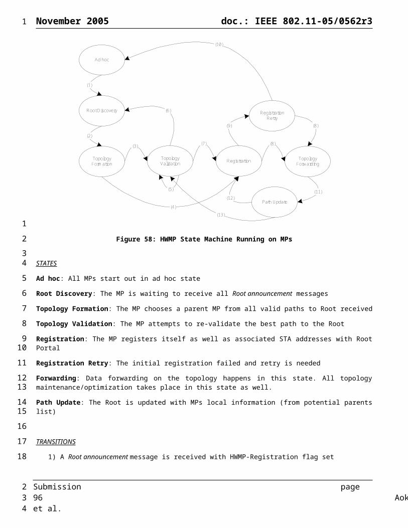
November 2005 doc.: IEEE 802.11-05/0562r3
Figure 62: Configuration of MP operating with IEEE802.1x (AS collocated with MP)
Figure 63: Configuration of MP operating with IEEE802.1x (AS no collocated with MP)
6.5.1.1 RSNA EstablishmentA MP’s SME establishes an RSNA in one of three ways.
6.5.1.2 Centralized 802.1X Authentication Modela) When using centralized IEEE 802.1X AKM in a WLAN Mesh, a MP’s SME establishes an RSNA as follows:
1) It identifies an MP as RSNA-capable and as connected to an AS from the MP’s Beacon or Probe Response frames.
2) It may invoke Open System authentication.
3) It negotiates cipher suites during the association process, as described in 802.11ma 8.4.2 and 8.4.3.
4) Each MP uses IEEE 802.1X to authenticate with the AS associated with the other MP’s Authenticator, as described in 802.11ma 8.4.6 and 8.4.7. Hence two 802.1X authentications happen independently. Note that the AS associated with a MP’s Authenticator may be implemented on the same device as the MP or may be remotely connected to the MP (implementation detail, beyond the scope of this proposal).
5) Each MP’s SME establishes temporal keys by executing a key management algorithm, using the protocol defined by 802.11ma 8.5. Hence two such key management algorithms happen independently between any two MP’s Supplicants and Authenticators.
6) Both MPs use the agreed-upon temporal key portion of the PTK and pairwise and cipher suite from one of the exchanges to protect the link. Each MP uses the GTK established by the exchange it initiated to protect the multicast and broadcast frames it transmits. See 802.11ma 8.3.2 and 8.3.3 for a description of the RSNA data protection mechanisms.
7) The MP may optionally establish a secure connection to a remote AS after establishing a secure connection to an MP that is connected to the remote AS. As described in Section 6.5.1, the establishment of a secure end-to-end connection between the MP and the AS is beyond the scope of this proposal.
Submission page 96 Aoki, et al.
1
12
3
45
6
7
89
1011
12
13
14
15161718
192021
22232425
262728
2

November 2005 doc.: IEEE 802.11-05/0562r3
8) In the case of a Mesh AP, if the Mesh AP has connectivity with an appropriate AS, the Mesh AP may take the Authenticator role for legacy STA authentication.
Figure 64 illustrates an example of the centralized authentication model for 802.11s.
Figure 64: Example of Centralized 802.1X Authentication Model
6.5.1.3 Distributed 802.1X Authentication ModelWhen using distributed IEEE 802.1X AKM in a WLAN Mesh, a MP’s SME establishes an RSNA as follows:
1) It identifies a peer MP as RSNA capable from the peer’s Beacon and Probe Response frames.
2) It may invoke Open System authentication
3) Each MP uses IEEE 802.1X to authenticate with the AS associated with the other MP’s Authenticator, as described in 802.11ma 8.4.6 and 8.4.7. Hence two authentications happen independently.
4) Each MP’s SME establishes temporal keys by executing a key management algorithm, using the protocol defined in 802.11ma 8.5. Hence two such key management algorithms happen independently between any two MP’s Supplicants and Authenticators.
5) Both MPs use the agreed-upon temporal key portion of the PTK and pairwise cipher suite from one of the exchanges to protect the link. Each MP uses the GTK established by the exchange it initiated to protect the multicast and broadcast frames it transmits.
6) In the case of a Mesh AP, the Mesh AP may take the Authenticator role for legacy STA authentication.
Figure 65 illustrates an example 802.1X distributed authentication. The 802.1x EAP exchange is shown serialized, but it can also be interleaved. The PMK derived from the exchange initiated by the MP with the highest MAC address is used to establish the PMKSA (8.4.9).
Submission page 97 Aoki, et al.
1
12
3
4
5
6
7
89
10
11
1213
141516
171819
20
21222324
2

November 2005 doc.: IEEE 802.11-05/0562r3
Figure 66 illustrates an example of the 4-way handshakes between three mesh points in a WLAN mesh network with the distributed authentication model.
Figure 65: Distributed 802.1X Authentication Example
Figure 66: Example 4-Way Handshakes in a WLAN Mesh
6.5.1.4 Pre-Shared Key Authentication ModelWhen using pre-shared keys (PSK) AKM in a WLAN Mesh, a MP’s SME establishes an RSNA as follows:
Submission page 98 Aoki, et al.
MP1 MP2
EAPOL-Start
EAPOL-Start
Request/Identity
Request/Identity
EAP Authentication
EAP Authentication
EAP Success
EAP Success
4-Way Handshake
4-Way Handshake
MP1 MP2 MP3
(MP1 Inits)
(MP1 Inits)
(MP2 Inits)
(MP2 Inits)
(MP3 Inits)
(MP3 Inits)
1
12
34
5
6
78
9
10
1112
2

November 2005 doc.: IEEE 802.11-05/0562r3
1) It identifies a peer MP as RSNA-capable from the peer’s Beacon and Probe Response frames.
2) It may invoke Open System authentication
3) Each MP uses procedure in 802.11ma 8.5 to establish temporal keys and negotiate cipher suite. Both MPs use the PSK as the PMK.
4) Both MPs use the agreed-upon temporal key portion of the PTK to protect the link. Each MP uses the GTK established by the exchange it initiated to protect the multicast and broadcast frames it transmits.
Note: Notice that PSK does not scale to meshes where multi-hop routing is required. In particular, it is infeasible to secure routing functionality when a pre-shared key is used in a mesh with more than two nodes, because it is no longer possible to reliably determine the source of any message.
[The authentication models described above are not exhaustive. A Mesh Network may support alternate authentication and key management models in either centralized or distributed fashion for certain usage scenarios (e.g. small growing enterprise settings).]
6.5.2 Extensible AKM (Informative)In this proposal, a Mesh Network may support flexible centralized or distributed 802.1X authentication and key management. 802.11u mechanisms may be leveraged to identify the type of AKM to use in a WLAN Mesh. A Mesh Point wishing to establish a secure link with another Mesh Point may use this mechanism to identify the AKM type and proceed to authenticate accordingly.
6.5.3 Mesh Management Frame SecurityThe objective for management frame security in TGs is to assure authenticity, integrity and privacy (where appropriate) of the management frames sent and received among Mesh Points on a link-by-link basis. The 802.11i-based link level authentication model identified in 6.5.1 will be used to support authentication, key distribution and encryption for management frames. There will be no separate management frame specific authentication and encryption architecture. Management frames will have the same level of security and use the same mechanisms as data frames. Wherever possible, the security mechanisms defined by the TGw will be utilized. The following sections define management frame security among mesh points (MPs). The security of management frames between Mesh APs and legacy STAs is beyond the scope of this proposal.
6.5.3.1 Forgery ProtectionAll class 3 management frames will be protected against forgery. Some management frames sent after authentication will be encrypted using the same mechanism as defined in 802.11i for data frames security. This mechanism protects data confidentiality and integrity as well as provides frame header integrity. Certain management frames are not encrypted. In this case, the frame header information and the data (when present) will be protected against forgery by computing the cryptographic message digest. The specific cryptographic technique employed for this purpose may be defined by TGw.
6.5.3.2 Confidentiality protectionSome management frames will be encrypted after authentication. The mechanism for this encryption may be the same as defined in the IEEE Std. 802.11i-2004 for the data frames.
6.5.3.3 Compatibility with 802.11i/r key hierarchyBoth 802.11i and 802.11r key hierarchies will be leveraged and supported instead of a separate key hierarchy specific to management frame security.
6.5.3.4 Incremental inclusion of new management framesNew types of management frames will be supported. The management frame protection mechanism will be generic enough to support vendor-defined management frames (6.2.4.6) as well as new standardized management frames.
Submission page 99 Aoki, et al.
1
1
2
34
56
789
10
111213
1415161718
192021222324252627
282930313233
343536
373839
404142
2
November 2005 doc.: IEEE 802.11-05/0562r3
6.5.3.5 Protection only after key establishmentIt is not possible to provide security prior to the establishment of the Security Association. As a consequence, the security of the Beacon and Probe Request frames cannot be supported among un-authenticated mesh points.
6.5.3.6 Fragmentation support for management framesSome management frames may be fragmented. Because of the need for header protection, the encryption and message digest computation will be handled appropriately per fragment.
6.5.3.7 Mesh Specific RequirementsWhen considering security, the mesh management frames, as well as IEEE Std. 802.11-1999 management frames, can be classified in two broad categories: those sent prior to authentication and those sent subsequent authentication. The management frames sent prior to authentication are Beacon, Probe Request/Response, Authentication Request/Response, the 4-way handshake. When 802.1X EAP is used, the data frames used are not protected at the link layer. The management frames sent and received after authentication are Beacon, Reassociation Request/Response, ATIM, Disassociation, and mesh routing management frames.
6.5.3.8 Management Frames sent pre-AuthenticationPrior to authentication, the management frames and the payload data cannot be secured unless a separate security scheme is implemented. The examples of such data are various information elements present in the Beacon and Probe Request/Response frames which are used in network discovery. Unless this data is signed or encrypted, it can only be used as a “hint” during the discovery stage and not trusted until the valid authentication context is established for the link. The alternative would be to utilize a pre-shared secret to sign or encrypt this data.
6.5.3.9 Management Frames sent post-AuthenticationAfter the authentication described in 6.5.1 takes place, the security of the management frames is based on the established context and using the encryption keys derived. The management frame body (data) is encrypted using these keys (unicast and broadcast, as appropriate). In addition, the integrity of the management frame header must be guaranteed through the cryptographic message digest computation.
6.6 Optimizations to EDCA for Mesh PointWe propose to use EDCA as defined in 802.11e as the basis for the 802.11s Media Access Mechanism. A set of recommendations on how to optimize EDCA for Mesh Point without changing the basic Media Access Mechanism is presented here.
6.6.1 Recommendation for NAV Duration Setting (Informative)
IEEE 802.11 compliant nodes are required to set their Network Allocation Vector (NAV) counters for durations indicated by the MAC in order to prevent collisions.
Submission page 100 Aoki, et al.
1
123
456
789
10111213
141516171819
20212223242526272829
303132333435
363738394041424344
2
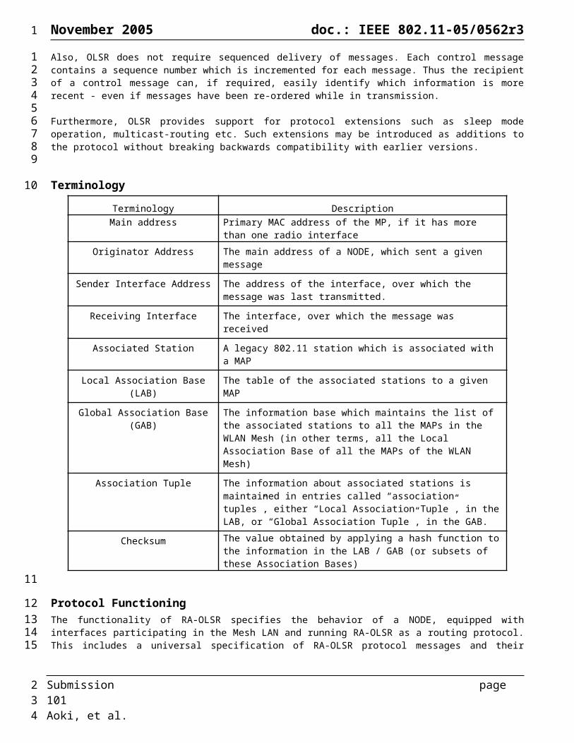
November 2005 doc.: IEEE 802.11-05/0562r3
a. Full NAV b. Packet by Packet NAV
c. NAV clearing mechanism
Figure 67: Different NAV settings.
Figure 67 depicts different available NAV setting mechanisms with TXOP enabled in EDCA. A Full NAV mechanism is shown in Figure 67a where each packet sets the NAV to protect the channel until the end of TXOP. Figure 67b depicts Packet by Packet (PbP) NAV mechanism, in which each packet transmission sets the NAV to protect the channel until the receipt of the ACK of the following DATA packet. The NAV clearing mechanism, shown in Figure 67c, is an optional mechanism in the standard which allows a station to clear its NAV if the station used information from an RTS frame as the most recent basis to update its NAV and there is no signal detected for 2 SIFS + CTS_duration + 2 SlotTime [IEEE 802.11:9.2.5.4]. This allows reuse of the channel in case the 4-way handshake can not be completed.
Clearly, implementation of different NAV mechanisms could potentially affect the performance of the system, depending on the network scenario and parameters. We have conducted simulation studies to understand the performance impact of different NAV mechanisms in mesh networks, and we have identified the scenarios where implementation of different NAV settings results in either gain or loss in network throughput.
Our simulation study shows that in general the performance of different NAV mechanisms is dependent on both network topology and system parameters. Simulation results indicate that the NAV clearing mechanism overall provides throughput gain. However, it is also worthwhile to point out that there exist scenarios in which the NAV clearing mechanism or similar mechanisms can result in throughput loss. Overall, we recommend that the NAV clearing mechanism is used by all Mesh Points.
6.6.2 Forwarding and BSS Traffic Interaction (Informative)
Since Mesh Point is only a logical entity, it is possible that it is physically collocated with an Access Point within one single device: a device that has both AP and MP functionalities collocated in it is called a Mesh AP. It is also possible to have a Mesh Point implemented on a device that also acts as an Application End Point, that is, in addition to participating in the mesh and forwarding frames on behalf of other Mesh Points, it also generate its own application traffic. In both of these cases, one single device has to forward a mixture of mesh traffic (with 4-address frame formats) and BSS traffic (with 3-address frame formats). How these two different kinds of traffic are being handled within a single device can have a profound impact on overall network performance. For example, the forwarding traffic tends to traverse the network through multi-hop path and hence may have already consumed significant amount of network resources before reaching a certain Mesh Point. Dropping such traffic basically renders all such resource as being wasted. The frames originated from a local BSS and destined to the mesh have only traversed one hop, and so dropping such traffic only has local impact. It is also possible that an aggressive STA with heavy traffic backlog in the BSS can potentially starve the neighboring mesh points in
Submission page 101 Aoki, et al.
RTS
CTS
DATA
ACK
SIFS SIFS SIFS
Source
Destination
time
OthersNAV
DATA
ACK
SIFS SIFS
RTS
CTS
DATA
ACK
SIFS SIFS SIFS
Source
OthersNAV
DATA
ACK
SIFS
RTS
CTS
DATA
ACK
SIFS SIFS SIFS
Source
Destination
Time
OthersNAV
DATA
ACK
SIFS
1
1
234567
8
9
101112131415161718192021222324252627282930
31323334353637383940414243
2

November 2005 doc.: IEEE 802.11-05/0562r3
the network. Such traffic prioritization may have different implication from the point of view of fairness and the prioritization policy may very well depend on the mesh network deployment scenario and the business model used. There are many implementation choices as how to best support such traffic prioritization within a single device like MAP. For example, one may choose to employ multiple radios to separate the BSS traffic and mesh forwarding traffic into different radios operating at different channels. Such choice is entirely implementation matter, outside the scope of this specification, but it is highly recommended that consideration is taken into account to separate BSS traffic and mesh forwarding traffic as much as possible and regulate the interaction between the traffic when complete separation is not possible. For example, it is recommended in Section 6.7 that a BSS traffic rate control mechanism be used in conjunction with intra-mesh congestion control to ensure the overall network performance.
6.7 Intra-Mesh Congestion Control
6.7.1 Motivation (Informative)
The original 802.11 MAC and all the recent MAC enhancements (e.g., 11e, 11i, 11k) are designed primarily for one-hop wireless networks. One of the key distinctions of mesh networks is their multi-hop data forwarding nature. 802.11 DCF and .11e EDCA provide no end to end consideration or coordination beyond a single hop at all. The Mesh Points in a mesh network get fair share of the channel access on a node-by-node basis without any coordination among the nodes. More specifically, each mesh point contends for the channel independently, without any regard for what is happening in the upstream or downstream nodes. One of the consequences is that a sender with backlogged traffic may rapidly inject many packets into the network which would result in local congestion for nodes downstream. Local congestion is defined as the condition when an intermediate mesh point receives more packets than it can transmit out in a pre-defined time window. The result of local congestion is that the local buffer gets filled up quickly, and eventually the buffer may become full and packets will have to be dropped from the buffer.
Local congestion exists in both wired and wireless networks, but the performance degradation it causes in wireless networks is even worse than in wired network, because of the very nature of wireless medium being a shared resource. In a wired network, the neighboring links across a flow can be regarded as independent resources and so bandwidth consumed by one link does not adversely affect the bandwidth available on another link. This is not true in a multi-hop wireless mesh networks any more. Typically multiple mesh nodes use the same channel to stay connected to the network, and so when a node is transmitting, other nodes in the vicinity have to refrain from transmitting. Therefore, if an aggressive upstream sender just blindly uses its share of the channel access time slots to inject packets into the network, while the downstream intermediate mesh points cannot effectively forward the packets to the final destinations, the channel access time slots used by the sender not only are wasted but also further reduce the channel access time slots available to the downstream nodes and hence adversely reduce the end to end throughput even more. Furthermore, hot spots may occur in a wireless mesh network where bandwidth consumed on one link in a neighborhood may adversely affect the bandwidth available to other links. This may cause unfairness due to the fact that the contention level seen by the nodes in a neighborhood may be different depending on each node’s location. Therefore in wireless networks congestion can occur even after the admission control is applied at the connection level.
Wired networks have been dealing with congestion control for a long time, and one of the effective tools to combat congestion has been end-to-end flow control implemented at the higher layers of the network stack. The TCP sliding window has been the primary example for end-to-end flow control at L4. Then why can’t we rely on higher layer flow control like TCP to solve this problem?
First of all, most multimedia applications (video and voice) use UDP transport which does not have any form of congestion control. Congestion control for UDP may not be as critical in a wired network as it is in a wireless network, because each individual hop in the wired network is isolated from other hops, but the neighboring hops in the wireless mesh network are sharing the same medium and so how to schedule across these neighboring links to maximize the network throughput becomes much more important for wireless network. Secondly, research (e.g.,[13]) also shows that TCP congestion control does not work well across a multi-hop wireless network and so simply relying on TCP is not a viable solution either.
To provide a good tradeoff between complexity and performance, we propose a simple hop-by-hop congestion control mechanism to address the problem. This mechanism must be implemented at each mesh point, and it includes three basic elements: local congestion monitoring, congestion control signaling, and local rate control. The basic idea is that each mesh point shall actively monitor its local channel utilization condition so that it can detect local congestion when it happens; three new mesh action frames are defined (“Congestion Control Request”, “Congestion Control Response” and “Neighborhood
Submission page 102 Aoki, et al.
1
123456789
10
111213141516171819202122232425262728293031323334353637383940414243444546474849505152535455
2

November 2005 doc.: IEEE 802.11-05/0562r3
Congestion Announcement”) to support the necessary hop-by-hop signaling between neighboring Mesh Points; upon receiving “Congestion Control Request” from a downstream Mesh Point, the upstream neighbors shall employ local rate control to help relieve the congestion being experienced downstream and upon receiving “Neighborhood Congestion Announcement” from a neighbor mesh point, the neighbors shall employ local rate control to help relieve the congestion being experienced in the neighborhood. The exact mechanism for local congestion monitoring and the exact trigger for congestion control signaling is outside the scope of this specification and entirely up to the implementation; but the frame formats for congestion signaling and the mechanism for local rate control are specified here.
6.7.2 Local Congestion Monitoring (Informative)In order to effectively control or even avoid congestion in the network, each Mesh Point has to monitor its local/neighborhood congestion condition so that when necessary, it can notify the neighborhood/upstream nodes of congestion, by transmitting a broadcast “Neighborhood Congestion Announcement” and/or a unicast “Congestion Control Request”. How the monitoring and congestion detection are implemented is a pure local implementation matter and is considered outside the scope of this specification. For the sake of completeness here two different monitoring and congestion detection mechanisms are provided as examples:
One way for detecting congestion is for each Mesh Point to keep track of its own effective MAC transmission and receiving rate for the packets to be forwarded (excluding the received packets destined for this Mesh Point), and to monitor the backpressure which is the difference between the aggregate receive and transmit rates. The goal of rate control is to maintain near zero backpressure at the local node. When the backpressure builds up significantly at the local node, the node informs its previous hop nodes by sending “Congestion Control Request” messages so that the recipient nodes can decrease their transmission rate accordingly by local rate control mechanism. Furthermore, the Mesh Point will inform its neighbors of the congestion level by sending broadcast signaling messages “Neighborhood Congestion Announcement”, so that its neighbors shall regulate their transmission rate depending on service differentiation criteria. The rate regulation should be limited by an expiration timer and should converge to a common EDCA parameter set in the neighborhood of the congested Mesh Point.
Another possible method for congestion detection is based on queue size. Following is an illustrative example: In this method we select upper and lower queue size thresholds. If the queue size is above the upper threshold, the node informs its previous hop neighbors by sending unicast signaling messages “Congestion Control Request Messages”, so that its previous hop neighbors can decrease their transmission rate to it accordingly by local rate control mechanisms. If the queue size is between the lower and the upper thresholds, the node again declares congestion, but this time, sends the unicast signaling messages “Congestion Control Request” messages to the upstream nodes with a probability given by
Furthermore, the possible methods described above for congestion detection may be based on queue size or difference between the MAC transmit and receive rates per upstream node as the downstream node may use different forwarding links for different upstream nodes’ traffic. This method may help to reduce the congestion problem caused by a particular forwarding link by rate limiting only the upstream nodes whose traffic is forwarded through this link.
The cause of the congestion may be estimated during the local congestion monitoring process in order to trigger the appropriate congestion control signaling and local rate control mechanism. For example, the channel access rate of a downstream node may be high within a neighborhood with a small channel load and still congestion may occur at this node that has high retry count due to forward link characteristics or its downstream node capacity. In this case, only the upstream Mesh Point should be informed of the congestion for the application of local rate control while the neighbors’ transmissions should not be affected. On the other hand, a high channel load value in the neighborhood where the congested Mesh Point determined the channel to be busy (CCA/NAV indications) in a manner that adversely affects its transmission attempts may be an indication to inform the neighbor Mesh Points about the congestion for the application of local rate control.
6.7.3 Congestion Control Signaling This specification does not define the exact conditions that would trigger the congestion control signaling. Such signaling can be done periodically or non-periodically. Note that the inclusion of “Expiration Timer” in the “Congestion Control Request” and “Neighborhood Congestion Announcement” frames provides enough flexibility for both cases.
Submission page 103 Aoki, et al.
1
12345678
91011121314151617181920212223242526272829303132
33
343536373839404142434445464748
49505152
2
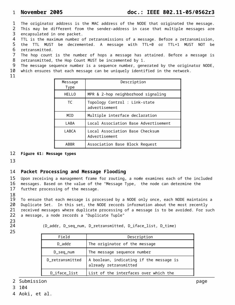
November 2005 doc.: IEEE 802.11-05/0562r3
“Congestion Control Request” message is transmitted as a unicast message. The frame contains the “Target Transmission Rate Element” which specifies the target data rate that should not be exceeded by the upstream Mesh Point transmitting to this node. When a node experiences local congestion, this target rate is generally already exceeded by the previous hop. The purpose of “Congestion Control Request” message is to notify the previous hop node of the congestion condition and to request from it to rate limit its transmission to help remove the congestion. The target rate is specified per AC per upstream neighbor so that the flow control can be done separately for each AC at each upstream neighbor. For example, this allows the nodes to request rate control of higher throughput traffic flows (such as bulk data or video traffic) while maintaining the QoS requirements of delay-sensitive flows (such as voice traffic) by leaving them unaffected by the congestion control scheme.
Nodes that receive a “Congestion Control Request Message” should reply with an “Offered Traffic Load” element. This message includes the offered traffic load of each access category at the node. This information can be used by the congested node to compute the target rate.
The “Neighborhood Congestion Announcement” message is transmitted as a broadcast message. The purpose of this message is to notify the neighbor Mesh Points of the congestion condition due to the high channel load in the neighborhood and to request that all neighbors rate limit their transmission in order to eliminate the congestion.
6.7.4 Target Rate Computation (Informative)In this section informative text and guidelines are provided on how nodes can compute the target rate to be communicated to the upstream nodes in two cases of channel congestion and channel underutilization.
In the case that a node detects congestion on the channel, it measures its outgoing traffic rate as an upper bound for the allowed aggregate incoming traffic to this node. Then the node computes the share of each upstream node of this rate. In order to compute the individual upstream nodes’ shares, the node can take into account any additional information it might have, for example the offered load of upstream nodes or system fairness policies, when computing the target rate. In the simplest case, where there is no additional information available, the share of each upstream node with traffic for this congested node is less than or equal to the measured outgoing traffic divided by number of such nodes. Note that it is recommended that the congested nodes utilize a more conservative approach in computing the target rate, as it would allow additional resources for initialization of new traffic flows.
When a node detects that the channel is underutilized, it needs to notify the upstream nodes of its available resources. Such notification is especially important in cases where the nodes reduce their traffic due to existing congestion and later on the source of congestion disappears. In order to ensure efficient utilization of the network resources, it is important that the upstream nodes be notified of the excess resources. However, the increase in the rate should happen in a way that does not result in congestion in the system. Computation of the target rate in this case requires additional information including the channel utilization (can be measured in the form of channel idle time), probability of collision (an indication of number of nodes contending for the channel), and upstream nodes’ offered load (to ensure efficient allocation of resources). Moreover, an accurate computation of target rate for each node can only be done if additional information is available regarding the channel quality (achievable transmission rate), average data packet size, and the MAC policy (for example whether RTS/CTS is used, in order to compute the MAC overhead per pkt transmission).
Assuming a network consisting of only a one-hop flow and an underutilized channel, which is in average idle for t time units per measurement window on average, one can compute the target increase rate n (packets per measurement window) as
, where C denotes average channel capacity, P denotes average packet size, and denotes average overhead
per packet in time units.
In the case that there exist more than one node contending for the channel, this upper bound target rate needs to be adjusted accordingly.
6.7.5 Local Rate Control Mechanism (Informative)Upon receiving either a “Congestion Control Request” or a “Neighborhood Congestion Announcement” message, the receiving node needs to reduce its effective MAC transmission rate accordingly by locally rate limiting its traffic. If the received message is a “Congestion Control Request” message, the node is only required to rate limit the traffic that it sends out to the neighbor requesting the congestion control. Note that reducing the MAC transmission rate does not mean
Submission page 104 Aoki, et al.
1
12345678
9
101112
13141516
171819
2021222324252627
28293031323334353637
3839
40
41
4243
4445464748
2

November 2005 doc.: IEEE 802.11-05/0562r3
changing the PHY layer modulation and encoding scheme to reduce the transmission rate of the radio. Typically a node can adjust its effective MAC transmission rate by internal scheduling algorithms that purposely delay the transmission of packets in a particular AC to a particular neighbor. How the rate control is implemented is an implementation choice and is hence outside the scope of this specification. Although there are many different ways of implementing a local rate controller, the objective of any implemented mechanism should be to keep the service differentiation and fairness in the neighborhood.
Here we mention two examples of rate control mechanisms. First example of the local rate control mechanism is based on dynamically adjusting EDCA parameters depending on the congestion condition in the node and/or the neighborhood. The EDCA parameters to be adjusted can be AIFSN, CWmin, or both. Use of such a mechanism would be especially effective when the source of a congestion-causing flow is a STA associated with a MAP. Although the BSS communication between a MAP and associated STAs is beyond the scope of this proposal (and the 802.11s standard in general), note that a MAP implementation may adjust the EDCA parameters for the BSS to alleviate congestion due to traffic generated by associated STAs. Thus, STAs do not require explicit knowledge of the congestion control scheme.
Another method of rate control, in response to a “Congestion Control Request”, is to utilize a shaper which includes a traffic meter. The meter measures the temporal properties of a rate-controlled AC traffic against the mean data rate of the “Congestion Control Request” message. If the packet is out-of-profile, the backoff timer’s timeout does not activate a TXOP transmission. Otherwise the backoff timer’s timeout activate a TXOP transmission.
[Editor's Note] The local rate control mechanisms provided above are informative examples only, but we may decide to standardize a specific rate control mechanism as normative text later. This issue is still under discussion and the resolution is TBD.
[Editor’s Node] The exact algorithms of the above mentioned mechanisms are still under investigation (TBD).
Note that while this specification focuses only on intra-mesh congestion control, it is important to point out that when some of the Mesh Points are also Mesh APs, it is critical for MAP to implement effective rate control mechanism for the BSS traffic in conjunction with rate control mechanism for mesh traffic. When a MAP receives Congestion Control Request or Neighborhood Congestion Announcement from its neighbor, it should effectively control both the mesh traffic transmission rate by itself and the BSS traffic transmission from its STAs so that fairness is maintained. The exact mechanism to control BSS traffic is out of scope for this specification. While one can dynamically adjust EDCA parameters to control mesh traffic, one can also employ the same method for MAP to regulate QSTA traffic by setting different EDCA parameters for the BSS. For legacy STA without EDCA support, MAP can also use CTS-to-self to discourage STAs from transmitting in the face of intra-mesh congestion.
Similarly, if a MP itself generates local application traffic to be forwarded into the mesh, it is also important to regulate the local traffic injection such that when it needs to ask its upstream neighbor to regulate the mesh traffic transmission rate, it also needs to regulate its own local traffic injection from its applications. In another word, it should treat its own local application traffic as if it is coming from another neighbor over the air, and it should not allow an aggressive local application saturate the queues when it asks other neighbor nodes to slow down.
Please refer to the reference [21] for simulation results studying different aspects of the congestion control scheme proposed here.
6.8 Multi-Channel MAC Using Common Channel Framework (Optional)Thus far the 802.11 MAC has been based on a single channel, i.e., all the devices on the network share the same channel. Using a multi-channel MAC, where transmissions can take place simultaneously on orthogonal channels, the aggregate throughput can be increased considerably. Multi-channel MAC protocols are often developed for multi-radio devices. The common channel framework described here enables the operation of single radio devices in a multi-channel environment. Known methods for channel access (e.g. DCF and EDCF) can be used within the framework.
Submission page 105 Aoki, et al.
1
12345
6789
101112
13141516
17
181920
21
22
23
242526272829303132
33
3435363738
39
4041
42434445464748
2

November 2005 doc.: IEEE 802.11-05/0562r3
MPs can utilize the common channel to select an available channel as shown in Figure 68. This is in essence a dynamic channel allocation scheme. The destination channel information (in this example channel n) is exchanged using the RTX and CTX frames followed by DATA frame transmission on the destination channel n. While the DATA frame transmission is ongoing on channel n, another transmission can be initiated on another destination channel m
RTXCommonChannel
DataChannel n
DataChannel m
CTX
SIFS
CTX
SIFS
CTX
SIFS
CTX
SIFS
RTX
DIFS
RTX
DIFS
DIFS
DATA
SwitchingDelay DIFS
DATA
SwitchingDelay
ACK
SIFS
ACK
SIFS CTX
SIFS
CTX
SIFS
RTX
DIFSSwitching
Delay
RTX
DIFSSwitching
Delay
DATA
SwitchingDelay DIFS
DATA
SwitchingDelay DIFS
ACK
SIFS
ACK
SIFS
Figure 68: Dynamic channel selection on the common channel
A single-radio MP on the common channel cannot communicate with MPs on other channels. At the same time, single-radio MPs on other channels cannot know the network status on the common channel and vice versa. A multi-channel MAC protocol designed for single radio should therefore address the following issues:1. Facilitate connectivity among arbitrary MPs that may be on different channels. 2. Facilitate protection of the ongoing transactions.
In order to address the foregoing issues the concept of a channel coordination window (CCW) is available in the framework. At the start of CCW, CCF-enabled MPs tune to the common channel. This enables arbitrary MPs to establish communication with each other. Secondly, at the start of CCW, the channel occupancy status is reset and MPs can re-negotiate channels. CCW is repeated with a period P, and the duration of CCW is usually a fraction of P.
The parameters CCW and P are carried in the WLAN Mesh capability information element defined in Section 5.3.3.1. The values of CCW and P should be synchronized among all MPs in the mesh network. The distribution of P and CCW that enables this synchronization is illustrated in Figure 69, where four beacons are shown. In this figure, the offset is the time (expressed in modulo P) elapsed after the start of P. In fact, MPs simply relay the values of P and CCW by copying these values from the beacons received from other MPs. Each MP computes its own value for prior to transmission of the beacon. The beacon transmission is coordinated as specified in Section 6.11. The protocol described in Section 6.3.3 can be reused to change the parameters.
Beacon frame
1 2 3 4
Time
P
Figure 69: Distribution of P and CCW using beacons
Optimal values of CCW and P may vary according to topology and application requirements.
6.8.1 Channel Coordination MechanismMPs shall tune to the common channel at the start of CCW. Once on the common channel, an arbitrary MP can initiate transmission by sending an RTX frame carrying information on the destination channel on which the communication can take place. The destination MP shall accept this request by transmitting a CTX frame carrying the same destination channel. It shall decline this request by sending the destination channel index set to the common channel. If the receiving MP accepts the RTX request, the MP pair shall switch to the destination channel in no longer than TBD s.
Submission page 106 Aoki, et al.
1
12345
67
89
101112131415161718192021222324252627
2829
3031
32333435363738
2

November 2005 doc.: IEEE 802.11-05/0562r3
TBD s after the completion of CTX, the transmitting MP shall perform a clear channel assessment for duration of DIFS. If the channel is found clear, the transmitting MP can send a DATA frame. If the receiving MP does not receive a DATA frame for SIFS + slot time after the transmission of the ACK frame, or after sending an ACK as in the case of TXOP, it shall return back to the common channel. If the transmitting MP does not receive an ACK frame in SIFS + slot time after sending a DATA frame, it shall switch back to the common channel. When that the channel is assessed as being busy during CCA, the transmission of DATA frame shall not be initiated and the MP pair shall return to the common channel after DIFS + slot time.
After returning to the common channel the transmitting MP shall initiate the backoff procedure.
An MP selects a destination channel to which it switches for transmitting frames. To facilitate channel selection, MPs use a channel utilization vector (U) of N channels, where U = [channel1, channel2, .., channelN], and channeli Î{0,1}, channeli = 0 indicates that channel channeli is available, and channeli = 1 indicates that channeli is occupied. At the start of the CCW, U is reset in accordance with the available channel list. The bits in U corresponding to those channels that need to be avoided, due to DFS requirements for instance are retained at '1'. The other bits are set to '0'. The vector is modified in accordance with successful requests. After an MP switches to a different channel and returns to the common channel, it shall no longer assume that channels marked as channeli = 0 are available. Those MPs that return back to the common channel after successful data exchange, and are unsure of the channel utilization states, shall not indicate any other destination channel than the one previously used.
If data channels are left available, a mesh point that did not succeed in obtaining a channel during CCW may select a channel based on its channel utilization vector (U). MPs can continue to exchange RTX and CTX even after CCW and indicate the destination channel to hop to. Figure 70 illustrates the channel coordination mechanism described above.
A transmitting MP that detects activity on the destination channel (e.g. channel is assessed as BUSY during CCA), should mark the channel as unavailable and should not return to this channel for TBD s. Unlike the list of channels that are unavailable due to regulatory requirements (e.g., DFS), other channels are marked as unavailable by individual MPs. Channels that are unavailable due to regulatory requirements are indicated using mechanism described in Section 6.10.1.
RTXA® B
CTXB® A
RTXC® D
CTXD® C
RTSE® F
CTSF® E
RTXB® A
CTXA® B
DATAE® F
ACKF® E
RTXC® D
CTXD® C
Common Channel
Channel m
Channel n
DATAA® B
ACKB® A
DATAC® D
ACKD® C
DATAB® A
Channel Coordination Window (CCW)
PChannel
Switching Delay DIFS
Figure 70: Channel coordination mechanism.
To prevent STAs from transmitting on the common channel during CCW, an MAP may transmit a CTS to itself frame to the STAs with the duration field set to cover the CCW duration. Another way is to prioritize WDS traffic over BSS traffic.
MPs (not MAPs) that switch channel set the duration field such that it only covers the dwell time on the common channel. This way STAs do not allocate unnecessarily long NAVs.
6.8.2 Handling different traffic scenarios in a mesh network
The usage of the common channel framework as described above is straightforward for decentralized traffic scenarios where MPs engage in communication on a point-to-point link.
Submission page 107 Aoki, et al.
1
123456789
101112131415161718192021222324252627282930
3132
33343536373839
404142434445
2
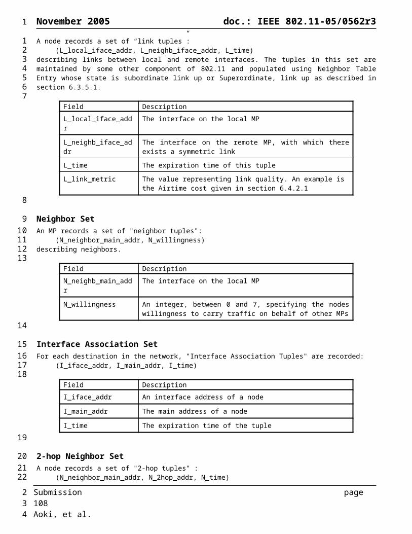
November 2005 doc.: IEEE 802.11-05/0562r3
During CCW After CCW
STA
Traffic on common channel Multiple Channels in BSS and WDS
Start of CCW
STA
Associated STAs allocate NAVs
MAP MAP
STA
MAP MAP
STASTA
MAP MAP
STA
BSS channel: Common channel:
During CCW After CCW
STA
Traffic on common channel Multiple Channels in BSS and WDS
Start of CCW
STA
Associated STAs allocate NAVs
MAP MAP
STA
MAP MAP
STASTA
MAP MAP
STA
BSS channel: Common channel:
Figure 71: Snapshots of BSS-heavy traffic scenario.
The framework also supports different traffic scenarios in which large amount of BSS traffic is generated. This is depicted in Figure 71. A WLAN mesh network may include one or more MAPs. If sufficient channels are available, each MAP can place its BSS on a separate channel. MAPs can switch to their BSS channels at the end of CCW. The other MPs can remain tuned to the common channel. In this way, MAPs are available for WDS traffic during CCW. On the other hand, within the common channel framework, it is also possible for the MAP to use the common channel for the BSS traffic.
Regardless of whether the MAP uses the common channel to communicate to its BSS or a separate channel, silencing the STAs during CCW facilitates participation in WDS traffic.
Only the MAPs switch the channel in this mode of operation. The BSS channel selection procedure of an individual MAP is compliant with known procedures in 802.11. Therefore the multiple BSS channel approach does not need new control or management frames. The choice of a large P may minimize the scheduling and the channel switching overhead. The specific scheme to manage scheduling parameters may vary with traffic pattern or network topology.
End of CCW After CCW
Multiple WDS ChannelsAssociated STAs allocate NAVs
During CCWSTA
Traffic on common channel
WDS channel:Common channel:
MAP MAP
STA
MAP MAP
STA
MAP MAP
STASTA STA
End of CCW After CCW
Multiple WDS ChannelsAssociated STAs allocate NAVs
During CCWSTA
Traffic on common channel
WDS channel:Common channel:
MAP MAP
STA
MAP MAP
STA
MAP MAP
STASTA STA
Figure 72: Channel coordination for the WDS-heavy traffic scenario.
Traffic scenario where large amount of traffic is generated among multiple groups of MPs can also be supported using the common channel framework. In a WLAN mesh network a group of MPs may generate heavy local traffic as compared with inbound or outbound traffic of the group. Moreover, it is possible that more than one group of MPs may exhibit this particular traffic pattern. The framework also supports this kind of pattern in that each group can form a logical, ad hoc cluster, which may vary over time, in the WLAN mesh network.
The channel switching need not take place on a per-packet basis, but takes place only once in a period P (here, switching from and back to the common channel is counted as a single switch) where the cluster members come together on an agreed upon channel. The channel switching can be accomplished without a strict timing constraint. Moreover, the frames carrying ad-hoc cluster information need not be control frames any more. Management frames (TBD) can be used to transmit channel information.
Submission page 108 Aoki, et al.
1
12
3456789
10111213141516
1718
19202122232425262728293031
2
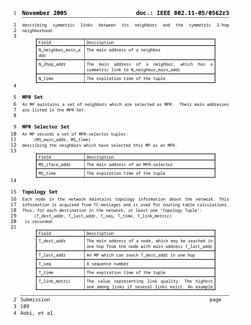
November 2005 doc.: IEEE 802.11-05/0562r3
After ad-hoc clusters are formed, communication takes place on orthogonal channels simultaneously without interfering with each other.
Using the common channel framework, the three scenarios described above can co-exist wherein each MP and MAP decides its mode of partipation individually.
6.9 Interworking Support in a WLAN MeshThis section describes a protocol for exposing broadcast LAN behavior of a WLAN Mesh at a Mesh Point collocated with a Mesh Portal (MPP) to enable bridging a layer-2 WLAN Mesh to other 802 LANs in a manner compatible with 802.1D.
Bridge Protocol
BridgeRelay802.11s
MAC(including L2 routing)
802 MAC
To/FromMesh LAN
Figure 73: The logical architecture of a Mesh Point collocated with a Mesh Portal (MPP).
6.9.1 Overview of Interworking in a WLAN MeshThe interaction between WLAN Mesh path selection and layer-2 bridging occurs in two places: at each Mesh Point collocated with a Mesh Portal (MPP) and on each node in the WLAN Mesh.
A packet being sent or forwarded by a Mesh Point collocated with a Mesh Portal has three possible final destinations:
A.1.A node in the Mesh
A.2.A node outside the Mesh that is reachable without traversing the Mesh
A.3.A node outside the Mesh that is reachable through the Mesh
A packet being sent by a node in the WLAN Mesh has two possible final destinations:
B.1. A node inside the Mesh
B.2. A node outside the Mesh
We assume that the Mesh Points collocated with Mesh Portals may participate in transparent layer-2 bridging, allowing users to build networks that include a WLAN Mesh in combination with other layer-2 networks. As such, each Mesh Point that is collocated with a Mesh Portal may participate in the spanning tree protocol and maintain a node table to determine through which port each node in the logical network can be reached.
6.9.2 Basic Layer-2 Bridging for a WLAN Mesh with Layer-2 Path SelectionIn this section, we describe some simple extensions that allow Mesh Points collocated with Mesh Portals to act as transparent layer-2 bridges. Note that the main goal in this section is to make the WLAN Mesh compatible with transparent bridging.
An implementation of layer-2 bridging for a WLAN Mesh will typically be integrated with layer-2 Mesh path selection (Figure 73). We assume that the Mesh LAN has facilities for delivering unicast, broadcast, and multicast packets. We also assume that the Mesh utilizes table-based layer-2 unicast path selection, where the forwarding table contains the next hop to each known destination, populated by either a proactive or reactive path selection mechanism. No assumptions are made about the broadcast and multicast facilities, and simple broadcast and multicast delivery mechanisms are described below as examples.
Bridging is enabled by handling unicast packets according to the following general outline:
1. Determine if the destination is inside or outside the Mesh.
Submission page 109 Aoki, et al.
1
123456
789
1011
121314
15
16
17
18
19
20
21
22232425
262728
293031323334
35
36
2
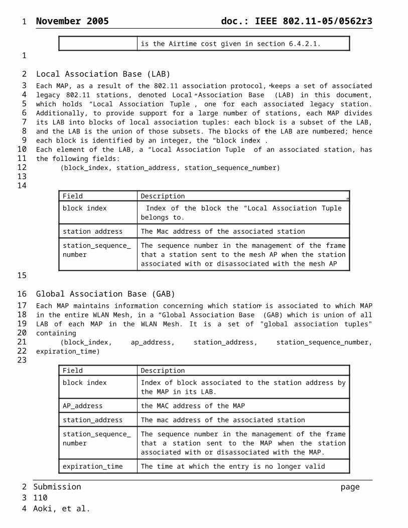
November 2005 doc.: IEEE 802.11-05/0562r3
2. For destinations inside the Mesh,
a. Use Mesh path selection
3. For destinations outside the Mesh,
a. Forward to all mesh points collocated with mesh portals, until the right MPP is identified
b. Eventually, identify the right MPP (may take time because we must wait for the destination node to send a packet) and deliver subsequent packets via unicast
The following subsections describe an implementation of the above approach (as well as broadcast and multicast support), including route table management, route discovery, packet forwarding, and the integration of these functions with the bridging tables.
6.9.2.1 Mesh Point Forwarding Table (Informative)Each Mesh Point (including each mesh point collocated with a mesh portal) maintains a layer-2 forwarding table for all known destinations. Each entry contains the layer-2 destination address and one of the following:
1. The address of the next hop along the route to the destination (if the node is known to be inside the Mesh)
2. The identity of the MPP through which the destination can be reached (if the node is known to be outside of the WLAN Mesh and the identity of the correct MPP is known)
3. A broadcast address (if the node is known to be outside of the WLAN Mesh but the identity of the correct MPP is not known)
A flag is required to distinguish entries of type 1 from types 2 and 3. Entries of type 1 and 3 may be created during route discovery (Section 6.9.2.2). Entries of type 2 are created during bridge table management (Section 6.9.2.4.3). If no entry is present, then it is not known whether the destination is inside or outside the network.
6.9.2.2 Determining if a Destination is Inside/Outside the MeshThe default mechanism to satisfy the first step described in Section 6.9.2 is to leverage the layer-2 path selection protocol to identify if a destination is inside or outside of the WLAN Mesh. Layer-2 routes to individual nodes within the Mesh can be identified either on-demand or proactively.
In the case of on-demand path selection, when a layer-2 forwarding table lookup fails (no entry is present for a given destination), layer-2 path discovery is initiated. If the destination is inside of the mesh, the path discovery mechanism will establish a path within the mesh to the destination. If the path discovery mechanism fails, the destination can be inferred to be outside of the mesh.
In the case of proactive path selection, an entry for each node in the mesh will be proactively maintained in the forwarding table. For each entry maintained by proactive path selection (the case 1 entries from Section 6.9.2), the node is known to be in the Mesh, and the next hop to the destination is known. When a table lookup results in no match, case 3 from Section 6.9.2 can be assumed (no explicit table entry is required).
If the MP fails to determine that a destination is inside the mesh, the broadcast address is placed in the forwarding table (case 3 from Section 6.9.2) for the destination.
6.9.2.2.1 Leveraging MPPs to Determine if a Destination is In/Out (Optional)Before utilizing the default mechanism of using the routing protocol to determine if a mesh point is inside or outside of the mesh, an MP may first send a portal update request message to its all known MPPs. This message can be sent as a unicast/multicast to the MPP. After receiving a portal update request message, each MPP looks at its proxy registration table to decide if they should reply. Three events may happen at this point.
1. MPP has an entry for the destination in its registration table. Destination is in the mesh and is presently owned by some MAP.
2. MPP has an entry for the destination in its registration table. But the destination is not in mesh.
Submission page 110 Aoki, et al.
1
1
2
3
4
56
789
101112
13
1415
1617
181920
21222324
25262728
29303132
3334
3536373839
4041
42
2
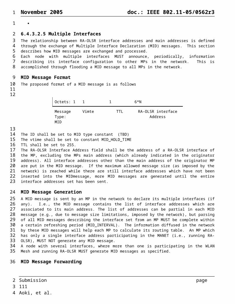
November 2005 doc.: IEEE 802.11-05/0562r3
3. MPP does not have any entry for the destination in its registration table.
In case 1, a portal update response message mentioning the MAC address of the owner of the STA is sent towards the MP. An MP should initiate a RREQ for this destination. In case 2, the MAC address to contact in the portal update response message is set to the MPP itself. An MP after receiving a portal update response message with MAC address of the destination set to MPP, updates its forwarding table accordingly. Now on, all the packets for the destination are sent as a unicast to the MPP. Finally in case 3, if the MP fails to receive any portal update response message within a bounded time, a broadcast address is placed in the forwarding table (case 3 from Section 6.9.2) for the destination.
6.9.2.3 Data Packet Forwarding
6.9.2.3.1 Broadcast Data PacketsAny layer-2 broadcast mechanism can be used to deliver broadcast packets, so long as the packets are delivered to all Mesh nodes. As an example, broadcast data packets can be delivered to all nodes in the Mesh by flooding. The originating node broadcasts the packet to neighboring nodes. Every node (including each mesh point collocated with a mesh portal) rebroadcasts a received flood packet exactly once (subsequently received copies are dropped). The identity of the source node, together with a monotonically increasing sequence number generated at each source, uniquely identifies each packet. In addition to rebroadcasting a flood packet, each Mesh Point collocated with a Mesh Portal also forwards the packet through all other active ports (in accordance with normal bridging procedures).
6.9.2.3.2 Unicast Data PacketsTo forward a unicast packet through the Mesh, a node looks up the destination in the layer-2 forwarding table (a mesh point collocated with a mesh portal must first use its bridging table to rule out case A.2 from Section 6.9.1). In the case of a reactive path selection scheme, if no entry is found, path discovery is initiated as described in Section 6.9.2.2. The path lookup (and potential path discovery in the reactive case) will have one of three possible results (as described in Section6.9.2):
The next hop to the destination. In this case, the packet is forwarded to the next hop as a unicast packet.
The identity of the MPP through which the destination can be reached . In this case, a second routing table lookup is performed to identify the next hop on the route to the MPP. If necessary, path discovery is performed (as described in Section 6.9.2.2). Once the next hop is known, the packet is forwarded to this next hop. The ultimate destination remains unchanged.
The broadcast address. In this case, the packet is delivered to all Mesh points collocated with mesh portals. For example, a simple flooding mechanism might be used, but the ultimate destination would remain the same, so delivery does not occur for any node within the network. At each MPP, three cases may occur:
1. The destination is known to be accessible through this MPP.
2. The destination is known to be accessible through another MPP.
3. Nothing is known.
Case 1 occurs when the destination is in the bridging table and the port listed is not attached to the Mesh. In this case, the packet is forwarded through the specified port. Case 2 occurs when the destination is in the bridging table and the port listed is attached to the mesh. In this case, the packet is dropped. Case 3 occurs when the destination is not in the bridging table. In this case, the packet is forwarded through all other active ports (in accordance with normal bridging procedures).
The forwarding procedure for Mesh Points collocated with Mesh Portals is shown in Figure 93. The forwarding procedure for all mesh points is shown in Figure 94 (reactive case) and Figure 95 (proactive case).
6.9.2.3.3 Multicast Data PacketsEach Mesh Point collocated with a Mesh Portal will forward a multicast packet to non-Mesh ports in accordance with the bridging protocol (e.g., 802.11D) and interworking procedures.
Submission page 111 Aoki, et al.
1
1
234567
8
910111213141516
171819202122
23
24252627
282930
31
32
33
34353637
3839
404142
2
November 2005 doc.: IEEE 802.11-05/0562r3
Any mechanism can be employed to deliver multicast data packets to the appropriate nodes within the Mesh. As an example, a simple mechanism could be based on flooding as described in Section 6.9.2.3.1.
See also section 6.4.4.5.
6.9.2.4 Maintaining Conformance with a Dynamic Bridging Protocol at MPPs (Informative)
The following subsections provide an example of how Mesh Points collocated with Mesh Portals (MPPs) may maintain conformance with a dynamic bridging protocol such as 802.1D.
6.9.2.4.1 Bridge LearningUsing the above data delivery mechanism, a Mesh Point collocated with a Mesh Portal can add entries to its bridge table in any of the following cases:
When forwarding a packet, the packet’s source address can be associated with the port on which the packet was received.
When proactive path selection is used, the bridge knows that all nodes in its routing table are accessible through a port attached to the Mesh.
When reactive path selection is used, route discovery packets can facilitate bridge learning. When a route request is received, the source of the route request packet can be associated with the port on which the route request was received. When a route response is received or overheard, the destination node (and all nodes along the path, if the path is included in the route response) can be associated with the port on which the route response was received.
When a mesh point collocated with a mesh portal shares information with another mesh point collocated with a mesh portal (see Section 6.9.2.4.3). For example, if another MPP indicates that a station is accessible through that MPP, then the station can be reached through the port attached to the Mesh.
6.9.2.4.2 Forming the Spanning TreeNo special action is required to support formation of the spanning tree. Spanning tree control messages are typically delivered to bridges in multicast packets. These packets are data packets from the point of view of the Mesh LAN, and they can be delivered from MPP to MPP (where each MPP is in the multicast group) using the normal Mesh multicast delivery mechanism (as described in Section 6.9.2.3.3).
6.9.2.4.3 Integration of Bridging Tables and Layer-2 Routing TablesLayer-2 forwarding table entries on individual nodes in the Mesh contain a duplicate subset of information maintained in the bridging tables stored in MPPs. Changes made to bridging tables reflect the location of new nodes, timeouts of unused entries, and node mobility. These changes will typically require an update to forwarding tables.
MPPs use a portal update message to inform Mesh nodes of changes in bridging tables. The portal update message is flooded in the network in a manner similar to data packet flooding (Section 6.9.2.3.1). The situations that result in a portal update message and the resulting actions taken by Mesh nodes are described below.
6.9.2.4.3.1Bridge Table Additions, Deletions, and ModificationsWhen a new entry is added to a MPP’s bridging table that points to a non-Mesh port, this MPP becomes the correct way to reach the destination. Since a new entry may not be the intended destination of any node in the Mesh, initially no action is taken. However, when a non-broadcast data packet is received using the flood mechanism (which occurs when the correct MPP is not known, as described in Section 6.9.2.3.2) by a MPP whose bridge table contains an entry for that destination which points to a non-Mesh port, the MPP sends a portal update add message containing the addresses of the destination node and the MPP identity. When a Mesh node receives the portal update message, it updates its forwarding table with the MPP address for this destination (as described in Section 6.9.2). When another MPP receives the portal update message, it updates its forwarding table and also updates its bridging table (as described in Section 6.9.2.4).
Submission page 112 Aoki, et al.
1
12
3
4567
89
10
1112
1314
1516171819
202122
2324252627
28293031
323334
353637383940414243
2

November 2005 doc.: IEEE 802.11-05/0562r3
Eventually, entries in bridging tables time out. When this occurs, the network no longer knows if the destination is inside or outside the mesh. In this case, the MPP immediately sends a portal update delete message, indicating that the given destination should be deleted from the routing tables of all nodes. Note that only bridging-related entries (cases 2 and 3 from Section 6.9.2) should be deleted. This message is also sent if a MPP receives a unicast data message destined for a node not listed in the MPP’s bridging table, as this indicates a stale routing table entry. We recommend that the timeout for bridge table entries be longer than the timeout for routing table entries, to prevent a bridge table entry from expiring prematurely.
A bridge table modification occurs when a bridge learns that a node is accessible via a port other than the one specified in the bridge’s current table entry. For the purposes of integration with a WLAN Mesh, a bridge table modification is handled as a deletion, followed by an addition. Since no action is taken after an addition, a MPP simply sends a portal update delete message, as describe above.
6.9.2.4.3.2Spanning Tree ChangesWhen the topology of the logical LAN changes, the spanning tree becomes invalid and must be reformed. When this occurs, nodes inside the Mesh remain in the Mesh and nodes outside the Mesh remain outside. However, the MPP through which a node inside the mesh may reach a destination outside the mesh may change.
When the spanning tree is reformed, each MPP sends a portal update invalidate message indicating that bridging tables have become invalid. In response, each Mesh node changes all route table entries that point to a specific MPP (case 2 in Section 6.9.2) such that they now point to the broadcast address (case 3 in Section 6.9.2). Entries which are actively being used will be relearned as bridge table entries are added (as described in Section 6.9.2.4.3.1). In the case of proactive path selection, nodes can simply delete the corresponding entry, which has the same effect.
6.9.2.4.3.3Node MobilityNode mobility in a bridged network can be within or between physical LANs. Four cases can occur:
A node may move within the topology of the Mesh LAN. Node mobility within the Mesh is handled by the path selection mechanism.
A node may move from a LAN outside the Mesh to another LAN outside the Mesh. In this case the MPP through which the node can be reached from within the Mesh may change. This case is no different from any other bridged network and can be handled through bridge learning and timeout of old bridge table entries. Note that when a bridge receives a portal update add message, it can also add or update a bridging table entry to reflect the new location of the destination.
A node may move from inside the Mesh to outside the Mesh. When reactive routing is used, this case is caught as a route error in the Mesh routing protocol. A subsequent route repair will discover that the node is no longer in the Mesh and will be handled as described in Section 6.9.2.2. When proactive routing is used, this case is identified during periodic route update rounds,
A node may move from outside the Mesh to inside the Mesh. As with any bridging scheme, this case will eventually lead to either a bridging table entry timeout or update. These cases are handled as described in Section 6.9.2.4.3.1.
6.9.3 VLAN support in a WLAN MeshWLAN mesh behaves as a backbone infrastructure which delivery the data frame between AP and MPP connecting the external network. In order to satisfy the conformance with the external network, WLAN mesh network is required to be compatible with the IEEE802 architecture, including IEEE802.1D, IEEE802.1Q and IEEE802.1F.
In case of VLAN tagging defined in IEEE802.1Q, a WLAN mesh network is required to carry VLAN tag information between AP and MPP.
VLAN tag consists of two fields: TPID (The Tag Protocol Identifier) and TCI (The Tag Control Information). TPID is two octets in length and used to represent MAC protocol type. The TCI is two octets in length and contains user_priority, CFI and VID (VLAN Identifier) fields.
Submission page 113 Aoki, et al.
1
123456
789
10
11121314
1516171819
2021
2223
24252627
28293031
3233
34353637
3839
404142
2
November 2005 doc.: IEEE 802.11-05/0562r3
IEEE802.1Q defines two header forms: Ethernet-encoded header and SNAP-encoded header. Ethernet-encoded header form requires a change to the IEEE802.11 MAC header to adopt VLAN tag field. In case of SNAP-encoded header, no revision to the IEEE802.11 MAC header is required. The new SNAP-encoded header for IEEE802.11 frame may be required.
Our proposal recommends the SNAP encoded header style for VLAN support in order to decrease the IEEE802.11 header overhead and minimize the impact to the current IEEE802.11 standard change.
6.10 Configuration and Management
6.10.1 Support for DFS in a WLAN Mesh If a mesh point detects the need to switch the channel of a logical radio interface (e.g. due to regulatory requirement for radar avoidance), the mesh point must inform neighboring mesh points to which an active association exists on the logical radio interface of the need to channel switch. The mesh point may request other mesh points or STAs to scan and provide measurements and/or run other algorithms to make a choice on which candidate channel to switch to (the detailed algorithm for choosing an appropriate channel is beyond the scope of this proposal).
Once the mesh point identifies the candidate channel to switch its logical radio interface to, it creates a new candidate channel precedence indicator value by adding a random number (in the range TBD) to the current channel precedence value. The mesh point then executes the channel cluster switch procedure described in Section Error: Reference source not found.
6.11 Mesh Beaconing and Synchronization
6.11.1 Synchronization
Synchronization and beacon generation services in a WLAN mesh are based upon the procedures defined in clause 11.1 of the IEEE 802.11-1999 specification for Infrastructure and IBSS modes of operation.
It is optional for an MP to support synchronization. An MP supporting synchronization may choose to be either synchronizing or unsynchronizing based on either its own requirements or the requirements of its peers. MP’s synchronization behavior is communicated through the “synchronization capability field” within the WLAN Mesh Capability element. The synchronizing behaviour for the two classes is defined as follows.
6.11.1.1 Unsynchronizing MPs
An unsynchronizing MP is a MP that maintains an independent TSF timer and does not update the value of its TSF timer based on time stamps and offsets received in beacons or probe responses from other MPs. An unsynchronizing MP may start its TSF timer independently of other MPs. The “Synchronizing with peer MP” bit in the “Synchronization Capability” field of the WLAN Mesh Capability element, when set to 0, indicates that an MP is currently an unsynchronizing MP. A MP that supports synchronization may elect to be an unsynchronizing MP if it is communicating with peers that are not requesting synchronization.
6.11.1.2 Synchronizing MPs (Optional)
A synchronizing MP is an MP that updates its timer based on the time stamps and offsets (if any) received in beacons and probe responses from other synchronizing MPs. The “Synchronized with peer MP” bit in the “Synchronization Capability” field of the WLAN Mesh Capability element, when set to 1, indicates that the MP is currently a synchronizing MP.
Synchronizing MPs should attempt to maintain a common TSF time called the Mesh TSF time. An MAP maintains the mesh TSF in terms of its TSF timer and its self TBTT offset such that the sum of the self TSF timer and the self TBTT offset
Submission page 114 Aoki, et al.
1
123
45
67
89
10111213
141516
17
1819
20212223242526272829
3031323334353637
3839404142434445
2
November 2005 doc.: IEEE 802.11-05/0562r3
equals the mesh TSF time. All beacons and probe responses by such MAPs carry the Beacon Timing IE to advertise its self offset value relative to the Mesh TSF time.
Synchronizing MPs translate the received time stamps and offsets (if any) from beacons and probe responses from other synchronizing MPs to their own timer base, and update their timer as described as follows:
Translated time stamp = Received time stamp + Received offset (if any) – Receiver’s offset (if any);
Any synchronizing MP will adopt the translated time stamp as its own if it is later than the timer value of self as described for IBSS mode of synchronization.
Synchronizing MPs may optionally choose to update their offsets instead of their timers. The offset update process in this case is as below.
If (received time stamp + received offset) > (self time + self offset)New self offset value = received time stamp + received offset – self time.
6.11.1.3 Interaction between synchronizing and unsynchronizing MPs
A synchronizing MP may or may not request synchronization from its peers. However, if an MP requests synchronization from its peers, it has to be a synchronizing MP at that time. Initially, an MP may be in unsynchronized state, but it may switch to synchronized state and vice-versa based on either its own requirements or the requirements of peers. An unsynchronizing MP may change into a synchronizing MP if it is capable of synchronizing, by setting its “Synchronizing with peer MP” bit to 1.
A synchronizing MP that associates with an unsynchronizing MAP and intends to enter power save mode may need to maintain additional information to wake up at the MAP’s DTIM interval during its PS operations as described below.
6.11.2 Beaconing
Any MP may choose to beacon either as defined in the IBSS mode or as defined in the infrastructure mode of operation in IEEE 802.11-1999 and 802.11E.
6.11.2.1 Beaconing by unsynchronizing MPs
Unsynchronizing MPs generate beacons according to the beacon generation procedures defined in clause 11.1.2.1 in IEEE 802.11-1999. Unsynchronizing MPs choose their own beacon interval and TSF independent of other MPs.
Unsynchronizing MPs may implement beacon collision avoidance defined in section 6.11.3 to reduce the chances that it will transmit beacons at the same time as one of its neighbors.
Unsynchronizing MAPs shall treat any associated non-AP MPs and neighboring LW-MPs operating in PS mode identical to legacy STA, meaning that the MAP shall assume that the MPs will wake up for the BSS DTIM beacon of the MAP in PS operations.
6.11.2.2 Beaconing by synchronizing MPs
Synchronizing MAPs generate beacons according to the beacon generation procedures described in clause 11.1.2.1 in IEEE 802.11-1999. The value of the aBeaconPeriod attribute used by synchronizing MAPs shall equal a sub-multiple of the Mesh DTIM interval. Synchronizing MAPs shall use and advertise a non-zero self TBTT offset value using the Beacon Timing element.
Submission page 115 Aoki, et al.
1
123456789
101112131415161718
1920212223242526272829
3031323334
35363738394041424344454647
484950515253
2

November 2005 doc.: IEEE 802.11-05/0562r3
Synchronizing non-AP MPs generate beacons according to the beacon generation procedures described for IBSS operation in the 802.11-1999 standard (section 11.1.2.2), unless acting as a designated beacon broadcaster (see section 6.11.2.3). A non-AP MP that receives a beacon from an MP with the Mesh ID the same as its own after TBTT and before being able to send its own beacon may cancel that beacon transmission. Specifically, the following rules apply for beacon transmission.
a. Suspend the decrementing of backoff timers for any non Beacon traffic.
b. Calculate a random delay uniformly distributed over the range of zero and twice aCWmin X aSlot time. The CWmin is as used for AC_VO.
c. Wait for the period of random delay, decrementing the random delay timer using the same algorithm as for back off.
d. If a beacon with the same Mesh ID arrives before the random delay timer expires, cancel the remaining random timer delay and the pending beacon transmission.
e. Send a beacon if the random delay has expired and no beacon has arrived during the delay period.
Each synchronizing MP can select its own Beacon interval, but all synchronizing MPs need to share a common Mesh DTIM interval. The Beacon intervals selected by MP must always be a submultiple of the Mesh DTIM interval. A synchronizing MP that establishes a Mesh selects its Beacon interval and the MP DTIM period and establishes the common Mesh DTIM interval of the mesh. Mesh DTIM interval equals the product of the beacon interval and the MP DTIM period. A synchronizing MP that joins an existing mesh needs to adopt the Mesh DTIM interval of the mesh.
Note that the Mesh DTIM interval and the BSS DTIM interval in MAPs do not have to be identical. MPs use the DTIM IE to advertise the Mesh DTIM interval, whereas the TIM IE is used for advertising the DTIM interval in a BSS. The DTIM Period of these IEs do not have to be identical since one will be used for the AP service while the other for the Mesh service.
An unsynchronizing MP intending to enter the powersave state shall become a synchronizing MP and request synchronization from peers prior to leaving the active state. MPs supporting PS operation may use the optional designated beacon broadcaster approach described in section 6.11.4 and 6.12.8.
An MP operating in Power Save will set its MP DTIM period to 1 prior to leaving the active state (meaning the beacon interval is the same as the mesh DTIM interval) and would therefore attempt to beacon only once on every Mesh DTIM interval.
A LW-MP (as described in section 4.2.2.1) may opt not to beacon if it is able to detect beacons from a beacon broadcaster. A LW-MP that opts not to beacon will have to resume beaconing if it does not receive any beacons for 3 Mesh DTIM intervals.
6.11.2.3 Designated Beacon Broadcaster
The designated beacon broadcaster approach may only be used by LW-MPs that support powersave operation. It enables to have a designated MP perform beaconing for a defined period of time while all other MPs defer from sending beacons.
An MP that serves as the designated beacon broadcaster will transmit its beacon using the procedure as described for infrastructure AP operation section 11.1.2.1 in the 802.11-1999 standard (i.e., will not use random backoff). The general operation of the power management in a mesh network is discussed in Section 6.12, specifically the beacon broadcaster is discussed in Section 6.12.8.
An MP supporting this option that received at least one beacon from an MP that is marked as Designated Beacon Broadcaster in the last 2 Mesh DTIM intervals will not schedule a Beacon for transmission.
6.11.2.3.1 Change of Beacon broadcaster
Submission page 116 Aoki, et al.
1
12345
6
7
89
10
1112
13
14151617181920212223242526272829303132333435
36373839404142434445464748
49
2

November 2005 doc.: IEEE 802.11-05/0562r3
The beacon broadcaster role must be changed periodically. An MP needs to relinquish its role as the designated beacon broadcaster after no more than MAX_CONT_BB Mesh DTIM intervals. A suggested value of MAX_CONT_BB is 32.
In every Mesh DTIM interval, the current beacon broadcaster sets the BB switch bit to 1 if it wants to change the beacon broadcaster (see Section 6.12.8.1). In this case the neighbor that is first in the neighbor list shall start acting as the beacon broadcaster and shall send the next Mesh DTIM beacon.
The BB has to make sure that the neighbor appearing at the head of the list is supporting power save transmission and Designated Beacon broadcasting.
If a neighbor assigned to be the beacon broadcaster fails to transmit its beacon (shuts down or goes out of range), other MPs will attempt to take over its role. MPs supporting the deterministic beacon broadcasting will start attempting to send beacons using the standard backoff procedure with a Neighbor list IE designating itself as the BB if it does not receive 3 consecutive beacons from the last designated BB.
If another MP already transmitted a Beacon with a neighbor list IE designating itself as the BB, then the MP will cancel its pending Beacon.
6.11.3 Mesh Beacon Collision Avoidance (MBCA) mechanism
MPs may optionally adjust their TSF timers to reduce the chances that they will transmit beacons at the same time as one of their neighbors.
Individual MPs may take steps either prior to, or during association, with a WLAN mesh to select a TBTT that does not conflict with its mesh neighbors. An MP may adjust its TSF timer if it discovers that its TBTT may repeatedly collide with the TBTT of a neighbor. Options a MP has for adjusting its TSF include advancing or suspending the TSF for a period of time.
An MP may collect and report information about the TBTT of neighboring synchronizing MAPs and unsynchronizing MPs using a variety of techniques. The following describes options to receive such information from neighboring MPs.
1. Information from synchronizing neighbors
MPs that are synchronizing collect the beacon timing information of their neighbors and report it through the beacon timing IE. This IE may be transmitted in selected beacons, and in action frames responding to requests for such information. Synchronizing MPs may choose any frequency of including the beacon timing information in the Beacon Timing IE in their beacons. The beacon timing information may also be requested via action frames (described in Sec. 6.11.3.1), with the response through the beacon timing IE in action frames. The action frame approach is especially useful for use by synchronizing MAPs to proactively detect and avoid beacon collisions. Synchronizing MPs are required to be able to respond to requests for such information using the beacon timing IE. Synchronizing non-AP MPs, when using the Beacon Timing IE, set the Self TBTT Offset field in the Self Beacon Timing field to 0.
2. Information from unsynchronizing neighbors
Unsynchronizing MPs may optionally collect and report beacon timing information of their neighbors. Since unsynchronizing MPs do not track the mesh TSF, they report beacon time offsets relative to their self TSF. This information either may be periodically transmitted in beacons at whatever periodicity the MP chooses, or it may be transmitted based on a request response approach through action frames. The Beacon Timing IE is used to report this information in beacons as well as in action frames as a response to request action frames. The Self Beacon Timing field in the Beacon Timing IE is set to all zeros in this case.
In addition, 802.11k beacon reports may be used by MPs to exchange beacon timing information of their neighbors, with the usage as defined by 802.11k.
Submission page 117 Aoki, et al.
1
1
23456789
10111213141516171819
20212223242526272829303132333435363738394041424344454647484950515253545556
2

November 2005 doc.: IEEE 802.11-05/0562r3
As an option, Synchronizing MAPs may occasionally delay their beacons after their TBTTs for a random time. The random delay is chosen so that the transmission time is interpreted by the MAP as not colliding with other beacons. This behavior further helps in discovery of neighbors through beacons in case they choose colliding offsets. The MBCA mechanism may then be used for choosing non-colliding offsets, in case any colliding offsets are observed
6.11.3.1 Action frames for beacon timing request and response
Neighbors’ Beacon Timing information may be requested and provided through action frames as described above. Table 30 shows the action field values to be used for the ‘Beacon Timing Request’ and ‘Beacon Timing Response’ frames. The category used for these frames is Beacon Timing, with the number T.B.D.
Action field value Meaning
0 Beacon Timing Request
1 Beacon Timing Response
2-255 Reserved
Table 30: Action field values for beacon timing category
6.11.3.1.1 Beacon Timing Request frame format
The beacon timing request frame is used to request a peer MAC its neighbors’ beacon timing information. The frame body of the Beacon Timing Request frame contains the information shown in Table 31.
Order Information
1 Category
2 Action
Table 31: Beacon Timing Request frame body
The category field is set to T.B.D., and the action field is set to 0.
6.11.3.1.2 Beacon Timing Response frame format
The Beacon Timing Response frame is used to respond to a Beacon Timing Request frame with neighbors’ beacon timing information. The frame body of the Beacon Timing Response frame contains the information shown in Table 32.
Order Information
1 Category
2 Action
3 Most Recent TBTT Time
4 Beacon Timing IE
Submission page 118 Aoki, et al.
1
12345
67
89
1011
12
1314
151617
18
19
20
2122
232425
2
November 2005 doc.: IEEE 802.11-05/0562r3
Table 32: Beacon Timing Response frame body
The category field is set to T.B.D., and the action field is set to 1. The Most Recent TBTT Time information is an eight byte field that reflects the most recent TBTT time of the transmitting MP, so that the beacon timing IE reflects information as if it was transmitted in a beacon at that TBTT. The beacon timing IE is as defined in 5.3.3.17.
6.12 Power Management in a Mesh (Optional)This sub-clause describes the power management mechanisms to use within a mesh network
6.12.1 Basic approach
A mesh point supporting power save operation may either operate in an active or power save state. The mesh point will advertise its power save state to all neighboring mesh points by using it’s beacons and by sending a Null-Data frame with the PS bit active.
Mesh points in power save mode shall periodically listen for DTIM beacons. Mesh point waking to receive a beacon will stay awake for a minimum period of ATIM window as indicated in their beacons, before returning to sleep.
Mesh points in power save mode shall also wakeup according to any negotiated schedule as part of TSPEC setup with other mesh points. The mesh point will remain awake until the end of service period
Mesh point wishing to communicate with mesh points that are in power save would buffer the traffic targeted for these mesh points. They could deliver the traffic to the mesh point in one of 3 ways:
1. Send traffic to these mesh points only on agreed schedules as negotiated as part of APSD (Automatic Power Save Delivery) TSPEC setup
2. Send directed or broadcast ATIM packets to mesh point in power save during ATIM window in order to signal them to remain awake and wait for further traffic
3. Send a single null data packet to mesh point in power save during their ATIM window in order to reactivate a flow that has been suspended or to signal power save state change.
All non-AP MPs that support the mesh power save mechanism shall support synchronization as described in 6.11. Such non-AP MPs shall become synchronizing MPs if they are not already, if they receive beacons or probe responses with the “Request Synchronization from Peers” bit set in the ‘Synchronization Capability’ field of WLAN Mesh Capability IE. All non-AP MPs that intend to enter powersave state shall be synchronizing MPs, as defined in clause 6.11, and shall request synchronization from peers through the ‘synchronization capability’ field in their WLAN Mesh Capability IE. MAPs may support power save with or without being synchronizing MPs (that is, even when acting as unsynchronizing MPs).
Any MP that wishes to communicate with an unsynchronizing MAP, and enters PS mode shall wake up for the BSS DTIM beacon of the MAP. If such an MP wishes to communicate with more than one unsynchronizing MAP, it shall wake up for the BSS DTIM beacons for each such MAP in addition to any Mesh DTIM TBTT which may be scheduled for its synchronizing MP neighbors.
LW-MPs that aim to communicate with their unsynchronizing MAP neighbors and enter PS state must wake up for the BSS DTIM beacons for each such MAP in addition to any Mesh DTIM TBTT which may be scheduled for its synchronizing MP neighbors. Alternatively, a lightweight MP may associate with a MAP as a simple STA if it intends to enter PS mode.
The PS operation of an unsynchronizing MAP is based upon IEEE 802.11 infrastructure power management operation. In particular, STAs (including MPs) changing Power Management mode shall inform the MAP of this fact using the Power Management bits within the Frame Control field of transmitted frames. Unsynchronizing MAP shall not arbitrarily transmit MSDUs to MP operating in a PS mode, but shall buffer MSDUs and only transmit them at designated times (during BSS DTIM intervals).
Submission page 119 Aoki, et al.
1
1
2
3
4567
89
101112131415161718192021222324252627282930313233343536373839404142434445464748495051
2

November 2005 doc.: IEEE 802.11-05/0562r3
6.12.2 Initialization of power management within a mesh
The following procedure shall be used to initialize power management within a new mesh or on joining an existing mesh.
A mesh point that joins a mesh will update its ATIM window and DTIM interval according to the received values from beacons in the mesh
The mesh point sets its own power save state and advertises it in its beacons A mesh point that creates a mesh would set the values of ATIM window, DTIM interval and power save state and
advertise them in its beacons The start of the ATIM window will be measured from TBTT
6.12.3 Mesh point power state transitions
A mesh point may change its state to powersave only if the following conditions are fulfilled:
The mesh point supports power save operation All of the mesh points that the mesh point is connected to (has peer relationships) are capable of transmitting traffic
to mesh points operating in power save mode
A mesh point changing power mode to power save will inform all it’s mesh neighbors of the change by sending a Null-Data frame to a broadcast address with the power bit in its frame control header set. The packet will be sent during the ATIM window of a DTIM beacon and will be repeated at least twice on two different DTIM intervals. If a beacon is received with the PS state bit of the specific MP in Neighbor list not updated, the MP will continue to send the Null-Data packet on the next DTIM. The mesh point will include a Mesh PS IE with a value of Powersave in its following beacons.
A mesh point changing power mode to active will inform all its mesh neighbors of the change by sending a Null-Data frame to a Broadcast address with the power bit in its frame control header cleared. The packet will be sent during the ATIM window of a DTIM beacon and will be repeated twice on two consecutive DTIM intervals. The mesh point will include a Mesh PS IE with a value of Active in its following beacons. The mesh point will transfer to the active state immediately with no relation to when the Beacons will be sent.
A mesh point operating in power save mode will set the power bit in the frame control header of every outgoing frame. A mesh point operating in active mode will clear the power bit in the frame control header of every out going frame.
A mesh point in power save mode will transition between awake and doze states according to the following rules:
A mesh point will enter awake state prior to every TBTT that matches the mesh DTIM interval If a mesh point that entered the awake state due to the DTIM TBTT event and had not sent an ATIM, did not receive
a directed or multicast ATIM may return to the Doze state following the end of the ATIM window If a mesh point received an ATIM frame it may return to doze state after receiving a packet with the more bit in the
control field cleared from all the sources that sent an ATIM packet to it. A mesh point that transitions to the awake state may transmit a beacon, but this would not prevent it from returning
to doze state following the ATIM window In addition a mesh point will enter awake state prior to every agreed schedule as negotiated as part of a periodic
APSD TSPEC exchange with other mesh points A mesh point entering awake state may return to doze state after receiving and/or sending a directed frame to/from
the specific flow for which this schedule was set with EOSP bit set or with the expiration of the maximal service interval for that flow.
A mesh point may transition to awake state if it has traffic to transmit at any given point of time
6.12.4 Frame transmission
Submission page 120 Aoki, et al.
1
1
23456789
101112
13141516171819202122232425262728293031323334353637383940414243444546474849505152
5354
2
November 2005 doc.: IEEE 802.11-05/0562r3
The following description applies to mesh points that are supporting power save operation. Mesh points that do not support this capability do not have to track the power save state of other mesh points and will only use the standard procedure for frame transmission.
A mesh point will store information on the power save state of all its neighbors by monitoring their beacon’s Mesh PS IE and by extracting information from the neighbor list IE in beacons of other MPs.
A mesh point considers the mesh to operate in a powersave mode if any one of its neighbors is operating in the powersave mode. In a mesh that operates in the Active state, frames may be sent at any time to other mesh points. For a mesh that operates in a power save scheme the following rules apply for transmission:
All broadcast and multicast traffic will be buffered by mesh points that perceive the mesh to operate in power save mode. These packets will be transmitted only on DTIM intervals
All unicast traffic targeted to mesh points in power save will be buffered. These packets will be transmitted only on the DTIM interval.
Mesh points will not transmit other types of packets but ACK, CTS, RTS, ATIM, Beacon & Null Data during the ATIM window.
Mesh points that transmit to mesh points in power save state (including broadcast and multicast) will set the More bit in frame control headers to indicate if more frames are to be transmitted for the specific destination.
All other aspects of ATIM based transmission are as defined in 802.11 specification section 11.2.2.4
For traffic that belongs to a flow for which an APSD TSPEC and schedule was setup with another mesh point, the transmission will be performed according to the agreed schedule.
6.12.5 Power management operation with APSDPower management operation with APSD in a mesh is very similar to the operation in a BSS.
The following are the modifications compared to the description provided in section 802.11-1999 Section 11.2.1.4
The Mesh supports periodic and aperiodic APSD operation modes. The periodic APSD mode is similar to Scheduled APSD. The aperiodic APSD is similar to Unscheduled APSD. The periodic and aperiodic APSDs use the same signaling as scheduled and unscheduled APSDs, but they can be used only with neighbors in a mesh that support it..
Use of aperiodic APSD in a mesh may be limited. It may only be used if one of the mesh points in the link is Active and the other in Power Save and EDCA is used for transport of the data. In this case the mesh point that operates in power save mode will be the one to initiate the data exchange by sending packets to the other mesh point triggering it to send the traffic back.
Periodic APSD can be used for all cases (i.e. both mesh points in power save or only one, EDCA or HCCA access).
The ADDTS request is modified to include a Schedule element that describes the requested schedule from the mesh point. The ADDTS response will include the Schedule that can be supported by the other mesh point and that should be used for this flow. If this schedule is not acceptable to the originating mesh point it may reattempt the ADDTS request with modified schedule or tear down the flow.
For periodic APSD both sides can initiate transactions as long as they are sent within the service interval defined. The service interval will last up to the maximal service duration as defined in the schedule IE or if EOSP is declared in frames sent/received for that flow. For a unidirectional flow the originating mesh point sets the EOSP when it wants to end the service interval. The interval will be considered terminated once the ACK is received for that packet (if ACK is required). For a bi-directional flow the service period will end only after both ends of the flow send a packet with EOSP bit set and the matching ACK packets are received.
Submission page 121 Aoki, et al.
1
123
45
678
910
1112
1314
1516
17
1819
20
21
2223
24
252627
282930
31
32333435
363738394041
2

November 2005 doc.: IEEE 802.11-05/0562r3
6.12.6 Power Save parameters selection
The power save operation of a mesh point is controlled by a set of global parameters. The following are the global mesh parameters with their default recommended values:
Beacon Period: 100TU DTIM period: 10ATIM Window: 10TU
Mesh points may wish to use other parameters but doing so may effect the power save efficiency and also delay the service initiation in the mesh.
6.12.7 TS ReinstatementA mesh point wishing to reinstate a TS with another mesh point that is operating in Power save mode will send a QoS-Null frame to the mesh point in power save during its ATIM window.
6.12.8 Beacon broadcasterBy default the beacon broadcaster in a mesh is rotating between the MPs. MAPs may need to send a beacon even if another MP had already sent a beacon on that same TBTT.
MPs that support power save operation must also support the deterministic beacon broadcasting selection as described in this section.
An MP not supporting this service will use a random backoff procedure for sending of Beacons as described for IBSS operation in the 802.11-1999 standard. An MP that receives a Beacon after TBTT and before being able to send its own beacon may cancel that beacon transmission. MPs that do implement this service and are set to be the Beacon Broadcaster (BB) will transmit Beacons immediately after TBTT or after a PIFS interval after the clearing of CCA in case CCA was active during TBTT.
An MP that supports this option and starts a mesh will set itself to be the Beacon broadcaster.
6.12.8.1 Change of Beacon broadcasterIt is possible to change the beacon broadcaster. In every DTIM period the current beacon broadcaster sets the BB switch bit to 1 if it wants to change the beacon broadcaster. In this case the neighbor that is first in the neighbor list shall start acting as the beacon broadcaster and shall send the next DTIM beacon.
The BB has to make sure that the neighbor appearing at the head of the list is supporting power save transmission and Beacon broadcasting.
If a neighbor assigned to be the beacon broadcaster fails to transmit its beacon (shuts down or goes out of range), other MPs will attempt to take over its role. MPs supporting the deterministic beacon broadcasting will start attempting to send beacons using the standard backoff procedure with a Neighbor list IE designating itself as the BB if it does not receive 3 consecutive beacons from the last designated BB.
If another MP already transmitted a Beacon with a neighbor list IE designating itself as the BB, then the MP will cancel its pending Beacon.
6.12.8.2 Beacon broadcaster power save stateBeacon broadcaster can enter the power save state where it sends only DTIM beacons and stays awake for the next beacon period. In this case, MPs shall not send any frames to the beacon broadcaster during normal beacon periods.
If beacon broadcaster is in power save state it sets the BB PS State bit to 1.
Submission page 122 Aoki, et al.
1
123456789
101112
131415
161718
1920
2122232425
26
27282930
3132
33343536
3738
394041
42
2
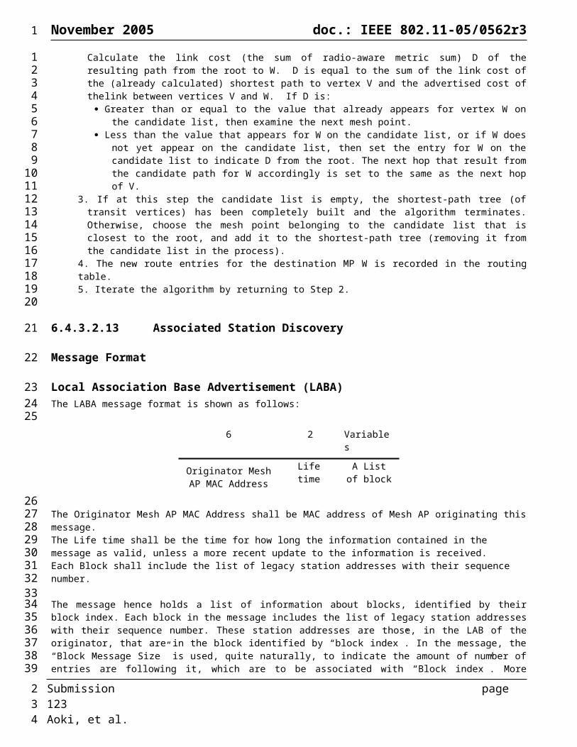
November 2005 doc.: IEEE 802.11-05/0562r3
6.12.9 Naive Mesh operation (Informative)
This section describes the operation of a naive mesh that does not include any Mesh APs and is also not supporting any routing capabilities.
This type of mesh would be mainly useful in cases were all Mesh point are maintaining a neighbor relationship with each other, as such it does not need to follow the association procedures and may use the three address format to directly exchange frames between the mesh members.
For this specific case the Mesh point does not have to support any of the route messages and link state announcements defined in this specification.
The mesh point will include in its WLAN Mesh Capability IE a Peer Capability field with only bit 15 set. This would signal that the MP is not supporting association with any other MPs and does not support any 802.1X capabilities.
Since the mesh point is not going to receive any association request, and it has no need to initiate one itself, it does not have to support the association messages as well as any of congestion control messages that can be exchanged only between associated peers.
The power save operation is an optional feature and may be implemented by the MPs of the Naive mesh.
A naive mesh supporting power save may use the basic power save scheme for simple data exchange and may optionally extend to include the APSD support for real time power save stream delivery.
6.13 Layer Management (Informative)The mesh MAC defines a set of protocol independent layer entities, service access points (SAPs) and management objects which support implementation of path selection and forwarding protocols. The layer entities are responsible for:
1. Re-transmission and filtering of unicast and multicast/broadcast MPDUs2. Maintenance of the information required to make re-transmission and filtering decisions3. Management of the above
The re-transmission of the MPDUs is handled by the mesh MAC. The maintenance of the information needed to make re-transmission and filtering decisions is handled by the MAC Layer Management Entity (MLME) and the Station Management Entity (SME). The management of these is handled by the SME.The re-transmission and filtering processing are time critical functions that are in the data path. The maintenance of the information needed to make re-transmission and filtering decisions is not time critical and only impacts the performance of the path selection protocol.Figure 74 illustrates the functional architecture provided by the Extensible Routing Framework entities and the principles of operation.
Submission page 123 Aoki, et al.
1
1234
567
89
1011
121314
15
1617
18
19
2021222324252627282930313233
2

November 2005 doc.: IEEE 802.11-05/0562r3
Figure 74: Extensible Routing Framework system architecture
6.13.1 Principles of OperationThe MPDUs are received and re-transmitted by the MAC Re-transmission entity. The Protocol entity is responsible for implementing the routing algorithm. It uses the internal MLME_SAP interface to send MMPDUs for route discovery and maintenance. The received MMPDUs are cached in the Learning cache. The Protocol entity retrieves data from the cache. Its internal algorithm is used to compute routes and maintain network topology. The Protocol entity adds and removes entries in the Forwarding and Filtering databases based on the internal computations. The Mesh Routing MIB is used to manage the entities that comprise the Extensible Routing Framework.
6.13.2 Inter-Layer ManagementFigure 11 in IEEE Std. 802.11-1999 needs to be modified to include the following entities supporting routing, as illustrated in Figure 75:
1. Re-transmit process (forwarding)2. Filtering database3. Forwarding database4. Learning cache5. Protocol entity
Submission page 124 Aoki, et al.
Re-transmission
Learning Cache
Forwarding database
Filtering database
Protocol entity
MMPDUs
MeshRoutingMIB
MLME_SAP
MLME_GET/SET
MPDUs
1
1
2
3
456789
10
111213141516171819
2

November 2005 doc.: IEEE 802.11-05/0562r3
Figure 75: Inter-layer management entities and their relationship and service access points (SAPs) used for internal communication (based on Figure 11 of IEEE Std. 802.11-1999).
6.13.3 Re-transmit ProcessWhen an 802.11 MPDU is received, its header is examined to determine the destination. If the destination is local, it is forwarded to the upper layer protocol. If its destination is not local, it is re-transmitted. The re-transmit process uses the information in the forwarding table to determine the address of the next hop destination.
6.13.4 Filtering databaseThe filtering decisions are based on the destination and source addresses and any group addressing policy.
6.13.5 Forwarding databaseThe forwarding database is used for making the re-transmission decision for unicast MPDUs.
6.13.6 Learning cacheThe learning cache keeps track of the protocol specific topology metrics collected from the MMPDUs received. This is a simple cache of the received protocol MMPDUs. It is maintained by the MLME and can be periodically queried by the protocol entity.
6.13.7 Protocol entityThe protocol entity implements the specific path discovery protocol logic, sends MMPDUs, queries the learning database, and updates the forwarding and filtering databases.
6.13.8 Service PrimitivesThe SME uses the MLME SAP interface to gain access to the entities needed to control the data path processing, send MMPDUs, retrieve status based on the received MMPDUs. These service primitives are defined in addition to the standard 802.11 GET and SET primitives which operate on the Mesh Routing MIB objects. The exact implementation details of these entities are beyond the scope of this standard.
Submission page 125 Aoki, et al.
MLME
PMD Sub-layer
DataLinkLayer
PhysicalLayer
MAC Sub-Layer
PLME
StationManagementEntity
MLME_GET/SET
PLME_GET/SET
Re-transmitprocess Learning
cache
Protocol entity
Forwarding database
Filtering database
PLCP Sub-layer
1
1
23
4
5678
910
1112
13141516
171819
2021222324
2

November 2005 doc.: IEEE 802.11-05/0562r3
6.13.8.1 MLME-SendMeshMgmt.requestThis primitive is used to send an MMPDU.
MLME-SendMeshMgmt.request (Interval,Count,Action,OUI ,Contents)
Name Type Valid Range DescriptionInterval Integer Time interval for sending
MMPDUsCount Enumeration Number of times to sent the
MMPDUAction Enumeration Management actionOUI Octet String IEEE OUIContents Octet String Protocol dependent information
6.13.8.2 MLME-SendMeshMgmt.confirmThis service primitive indicates the result of the request.
6.13.8.3 MLME-RecvMeshMgmt.requestThis service primitive is used to retrieve one or more received MMPDUs.
MLME-RecvMeshMgmt.request (Count,Action,OUI,Vendor specific contents)
Name Type Valid Range DescriptionCount Enumeration Number of items to retrieveAction Enumeration Management actionOUI Octet String IEEE OUIContents Octet String Protocol dependent information
6.13.8.4 MLME-RecvMeshMgmt.confirmThis service primitive indicates the result of the request.
6.13.8.5 MLME-PathAdd.requestThis service primitive is used to add a path to the forwarding table.
MLME-PathAdd.request (OUI,Id,Dest,Gw,Metrics)
Name Type Valid Range Description
Submission page 126 Aoki, et al.
1
123456789
1011
12
1314
15161718192021222324
25
2627
282930313233343536373839
2
November 2005 doc.: IEEE 802.11-05/0562r3
OUI OctetString IEEE OUIId OctetString Protocol IdentifierDest MACAddress Destination MAC address
matched with the contents of DA field
Gw MACAddress Next hop MAC address matched with the contents of the RA field
Metrics OctetString Re-transmission metrics used to rank alternate routes. May be matched with the user priority bits for QoS – type routing.
6.13.8.6 MLME-PathAdd.confirmThis service primitive indicates the result of the request.
6.13.8.7 MLME-PathRemove.requestThis service primitive is used to remove a path from the forwarding table.
MLME-pathRemove.request (OUI,Id,Dest,Gw,Metrics)
Name Type Valid Range DescriptionOUI OctetString IEEE OUIId OctetString Protocol IdentifierDest MACAddress Destination MAC address
matched with the contents of DA field
Gw MACAddress Next hop MAC address matched with the contents of the RA field
Metrics OctetString Re-transmission metrics used to rank alternate routes. May be matched with the user priority bits for QoS – type routing.
6.13.8.8 MLME-PathRemove.confirmThis service primitive indicates the result of the request.
7 References[1] IEEE Std 802.11®-1999 (Reaff 2003)
Wireless LAN Medium Access Control (MAC) and Physical Layer (PHY) Specifications
[2] IEEE P802.11e/D8.0, February 2004(Draft Amendment to IEEE Std 802.11, 1999 Edition (Reaff 2003))Medium Access Control (MAC) Enhancements for Quality of Service (QoS)
[3] Project Authorization Request (PAR) for IEEE 802.11s.http://www.ieee802.org/11/PARs/11-04-0054-02-0mes-par-ieee-802-11-ess-mesh.doc
Submission page 127 Aoki, et al.
1
1
23
456789
10111213
1415
161718
19202122
232425
2627
2
November 2005 doc.: IEEE 802.11-05/0562r3
[4] Five Criteria for IEEE 802.11s.IEEE 802.11-04/0056r1
[5] IEEE 802.11s Call for ProposalsIEEE 802.11-04/1430r12
[6] Terms and Definitions for 802.11sIEEE 802.11-04/1477r4
[7] Functional Requirements and Scope for 802.11sIEEE 802.11-04/1174r13
[8] Comparison Categories and Informative Checklists for 802.11sIEEE 802.11-04/1175r10
[9] Usage Models for 802.11sIEEE 802.11-04/662r16
[10] Informative Reference Bibliography for 802.11sIEEE 802.11-04/1543r4
[11] Z. Fu, P. Zerfos, H. Luo, S. Lu, L. Zhang, and M. Gerla, “The impact of multihop wireless channel on TCP throughput and loss”, In Proceedings of IEEE INFOCOM’03, San Francisco, CA, April 2003.
[12] C. Perkins, E. Belding-Royer, S. Das, “Ad hoc On-Demand Distance Vector (AODV) Routing”, IETF RFC 3561, July 2003.
[13] Z. Fu, P. Zerfos, H. Luo, S. Lu, L. Zhang, and M. Gerla, “The impact of multihop wireless channel on TCP throughput and loss”, In Proceedings of IEEE INFOCOM’03, San Francisco, CA, April 2003.
[14] T. Clausen and P. Jacquet, “Optimized Link State Routing Protocol (OLSR),” IETF RFC 3626, October 2003.
[15] J.J. Garcia-Luna-Aceves and M. Spohn, “Source-Tree Routing in Wireless Networks”, In Proceedings of the 7th International Conference on Network Protocols, IEEE ICNP 99, Toronto, Canada, October 1999.
[16] Xiaoyan Hong, Kaixin Xu, and Mario Gerla, "Scalable Routing Protocols for Mobile Ad Hoc Networks, “IEEE Network, special issue on Scalability in Communication Networks, July-Aug, 2002, pp. 11-21.
[17] IEEE Std. 802.11i-2004 Amendment 6 – Security Enhancements
[18] 11-05-0404-01-0ads-tgw-protocol-security-requirements.doc
[19] IEEE Std. 802.11i-2004 Amendment 6 – Security Enhancements
[20] 11-05-0404-01-0ads-tgw-protocol-security-requirements.doc
[21] 11-05-0568-00-000s-seemesh-simulation-congestion-control.doc
Submission page 128 Aoki, et al.
1
12
34
56
78
910
1112
1314
1516
1718
1920
21
2223
2425
26
27
28
29
30
2
November 2005 doc.: IEEE 802.11-05/0562r3
[22]
Appendix A Radio Metric AODV Example and FlowCharts
A.1 An Example
Submission page 129 Aoki, et al.
2
3
1
1
1
A
E
C
B
D
2
2
F
H
1
G I
11
2
3
1
1
1
A
E
C
B
D
2
2
F
H
1
G I
11 RREQ
RREQ
1
1
23
456
7
2

November 2005 doc.: IEEE 802.11-05/0562r3
Submission page 130 Aoki, et al.
2
3
1
1
1
A
E
C
B
D
2
2
F
H
1
G I
11
2
3
1
1
1
A
E
C
B
D
2
2
F
H
1
G I
11
2
3
1
1
1
A
E
C
B
D
2
2
F
H
1
G I
11 RREQ
RREQ
RREQ
1
1
2
3
2
November 2005 doc.: IEEE 802.11-05/0562r3
Submission page 131 Aoki, et al.
2
3
1
1
1
A
E
C
B
D
2
2
F
H
1
G I
11
2
3
1
1
1
A
E
C
B
D
2
2
F
H
1
G I
11
2
3
1
1
1
A
E
C
B
D
2
2
F
H
1
G I
11 RREQ
RREQ
RREQ
1
1
2
3
2
November 2005 doc.: IEEE 802.11-05/0562r3
Figure 76: Example network.
Consider an example network shown in Figure 76. In the figure, lines between nodes indicate that they are neighbors (i.e) they are in radio-range with each other. The numbers beside the lines indicates the metric for the corresponding link. In this example, the link qualities are assumed to be symmetric. Radio Metric AODV should determine routes between nodes that will minimize the end-to-end metric.
Assume that node A attempts to find a route to destination node D and sends a RREQ (OSN=2, RREQID=2, Dest=D, DSN= 0). Assuming there is no packet loss, node D would get 3 copies of this RREQ each traversing a different path: A-E-D, A-F-D and A-B-C-D. Let us assume that the three RREQs reached D in the following order: A-E-D, A-F-D, A-B-C-D. On receiving the RREQ through A-E-D, node D first creates a route to node A through E. At this point, the upstream route to the source (node A) would have been established in node E and D. Then, node D sends a RREP (Dest=D, DSN=2) along the route D-E-A. The RREP establishes the downstream route to node D on nodes E and A. Table 33, Table 34, and Table 35 show the routing tables in nodes A, E and D respectively at this point.
When node D receives the RREQ that came along A-F-D, it determines that this RREQ came along a path with a better metric to A than the current route (4 vs. 5). Therefore, node D modifies the nexthop from E to F and the metric from 5 to 4. D then forwards the RREQ and also sends a unicast RREP (D, 3) back to A via F. Similarly, when D receives the RREQ that came along A-B-C-D, it modifies the nexthop to A from F to C, as this RREQ came along a better route than the current route. The RREQ is then forwarded and a unicast RREP is sent via node C. The RREP establishes the route to D in the intermediate nodes C and B as well as the source node A. Table 36, Table 37, Table 38 and Table 39 show the routing tables in nodes A, B, C and D respectively at this point.
In order to maintain an optimal route between A and D, A sends maintenance RREQs. Assume that A sends a maintenance RREQ (3, 3, D, 2) and that the RREQ reaches D in the order A-E-D, A-F-F, and A-B-C-D. Since D has a better route to A through C and since A’s sequence number in the RREQ (3) is not newer than what is in D’s route table by at least HWMP_RREQ_LOSS_THRESHOLD, node D will not modify its current route to A. Instead, it stores this route (through E) as an alternate route to A, and starts a rreq_wait_alarm for this RREQ that would go off in current_time+HWMP_NETDIAMETER_TRAVERSAL_TIME. It is assumed that HWMP_NETDIAMETER_TRAVERSAL_TIME is configured large enough for a RREQ to traverse one-way along the diameter of the network. This would guarantee that node D receives all copies of a RREQ originating from A within that time. In particular, node D would receive the RREQs that traversed the paths A-F-D and A-B-C-D before the timer goes off. When node D receives the RREQ that came along A-F-D, it does not modify the current route as before. But since this RREQ offers a better route to A than the current alternate route, it changes the alternate route to go through F. When the RREQ arrives via A-B-C-D, node D keeps the current route, since it is still the optimal one, and changes the sequence number on the route to the one in the RREQ. Node D also cancels the rreq_wait_alarm for this RREQ, forwards the RREQ and sends a unicast RREP back to A using the current route via C. The rest of this section considers and illustrates a few hypothetical situations that may happen in the network from this point onwards.
Example Scenario1Consider a scenario when the metric along the path A-B-C-D became worse. In particular, say the metric along the link A-B changed from 1 to 4. When A sends the next maintenance RREQ (4, 4, D, 3), the processing of the RREQs that come along A-E-D and A-F-D in node D will be similar to the processing of the previous maintenance RREQ (3, 3, D, 2). But when D receives the RREQ that traversed A-B-C-D, it finds that the current route’s metric has deteriorated (from 3 to 6) and modifies the route to use the alternate route (via nexthop F) since its offered metric is better than the current route (4 vs. 6). As done before, when the route is modified, node D cancels the rreq_wait_alarm for this RREQ, forwards the RREQ and sends a unicast RREP (D, 4) through the current route to A (via nexthop F).
Example Scenario2Assume that A sends the maintenance RREQ (4, 4, D, 3) and that the RREQ reaches node D along the paths A-E-D and A-F-D, but never along the path A-B-C-D (gets lost). In this case, processing the received RREQs will be similar to the processing of the previous maintenance RREQ along the same paths. But since the RREQ never comes along the current route, the rreq_wait_alarm does not get cancelled. When the timer expires, node D forwards the RREQ with the information in its current route to the source A (via C) and sends a unicast RREP (D, 4) along the current route.
Example Scenario3
Submission page 132 Aoki, et al.
1
1
2345
6789
101112
1314151617181920
2122232425262728293031323334353637383940414243444546474849505152535455
2
November 2005 doc.: IEEE 802.11-05/0562r3
Assume that HWMP_RREQ_LOSS_THRESHOLD=2. Let us further assume that the maintenance RREQs from A with OSN 3 and 4 got lost somewhere along the path A-B-C-D. Now when node D receives the RREQ (5, 5, D, 4) along the path A-E-D, it will modify its route to A to go through nexthop E even though the metric on this route is worse than the current route through C. This is because, the sequence number difference between what is in the received RREQ and the current route entry is greater than HWMP_RREQ_LOSS_THRESHOLD, which indicates that too many RREQs were lost along the current route.
Example Scenario4Assume that node A generated 3 RREQs, one each for destinations G, H, and I. Also, let us say that A incremented its sequence number every time it sent a RREQ. So, the RREQs for G, H, and I would be RREQ4 (4, 4, G, 0), RREQ5 (5, 5, G, 0), and RREQ6 (6, 6, I, 0) respectively. Assume that all the three RREQs reach D along the path A-E-D even before RREQ4 reaches D along the path A-B-C-D. In this case, D would change its route to A to go through nexthop E after processing RREQ6, since the A’s sequence in the RREQ indicates that it has not received more than HWMP_RREQ_LOSS_THRESHOLD RREQs along its the current route to A. But shortly after processing this, all the three RREQs (4, 5, and 6) arrive at D along A-B-C-D. Now D would change its route to A back to its original route through nexthop C. This route flapping can happen every time a burst of RREQs originate from a node with unique and increasing originating sequence numbers. Radio Metric AODV avoids this situation by imposing that nodes not increment their current sequence numbers if the time at which they sent the first RREQ with the current sequence number is less than HWMP_NETDIAMTER_TRAVERSAL_TIME than the current_time. In the current example, node A would have sent the burst of RREQs with the same sequence number, but with different RREQ IDs. This would prevent node D from switching its route to the inferior route through E even if the burst of RREQs arrive at D along A-E-D.
Table 33: Routing Table in node A
Dest. DSN Nexthop Metric Alternate Route
E 0 E 2 InvalidD 2 E 4 Invalid
Table 34: Routing Table in node E
Dest. DSN Nexthop Metric Alternate Route
A 2 A 2 InvalidD 2 D 2 Invalid
Table 35: Routing: Table in node D
Dest. DSN Nexthop Metric Alternate Route
E 0 E 2 InvalidA 2 E 4 Invalid
Table 36: Routing Table in node A
Dest. DSN Nexthop Metric Alternate Route
B 0 B 1 InvalidD 2 B 3 Invalid
Table 37: Routing: Table in node B
Dest. DSN Nexthop Metric Alternate Route
A 2 A 1 InvalidC 0 C 1 InvalidD 2 C 2 Invalid
Submission page 133 Aoki, et al.
1
123456789
1011121314151617181920212223
2425
2627
28
29
3031
2

November 2005 doc.: IEEE 802.11-05/0562r3
Table 38: Routing: Table in node C
Dest. DSN Nexthop Metric Alternate Route
A 2 B 2 InvalidB 0 B 1 InvalidD 2 D 1 Invalid
Table 39: Routing: Table in node D
Dest. DSN Nexthop Metric Alternate Route
C 0 C 1 InvalidA 2 C 3 Invalid
Table 40: Routing: Table in node D.(case 2)
Dest. DSN Nexthop Metric Alternate Route
C 0 C 1 InvalidA 3 C 3 DSN=3
Nexthop=FMetric=4
Example Scenario 5Station management and multiple interface operation.Consider an example network shown in Figure 77 where MAP with multiple radio interfaces has legacy stations. Assume the station X transmits packets to station Z. MAP A transmits RREQ frame in behalf of station X, because station X does not have routing functionality. In the same way, MAP G transmits RREP frame in behalf of station Z because station Z cannot transmits RREP frame. Routing table in MAP A is shown in Table 27. Destination Sequence number is managed in MAP G. If station X moves from MAP A to MAP C, MAP A receives the disassociation frame or detects station X association timeout, then MAP A sends RERR message to MAP B in precursor list.
Example Scenario 6Assume that station Y transmits data frame to station Z when MAP A has a path from X to Z. There are two options in this ptorocol. One is that MAP A forwards the packets from Y by using the path from X to Z. The routing table 27 is used in this case. Another is that MAP A search the another path by transmitting RREQ frame (Elements #5). In this case, routing table has source field entry as shown in Table 28. The second case option is useful when the destination is a device that has heavy traffic with many staitions such as GW. Each MAP can use the different interface to transmit data frame to the same destination if the source of packet is different, which takes an advantage to improve the load balance in each radio.
Submission page 134 Aoki, et al.
1
12
34
5
6
789
101112131415161718192021222324
2
November 2005 doc.: IEEE 802.11-05/0562r3
A
B
C
D
E
F
G
X
Y
Z
Figure 77: An example of netwrk with multiple interface MAP and legacy stations.
Table 27: Routing Table in MAP A
Table 28: Routing Table in MAP A (source-destination pair)
Submission page 135 Aoki, et al.
Dest. DSN Nexthop Metric Alternate Route
Z 0 B#1 1 Invalid
Dest. DSN Source Nexthop Metric Alternate Route
Z 0 Y B#1 1 Invalid
1
12
345
67
8
910
1112131415
2
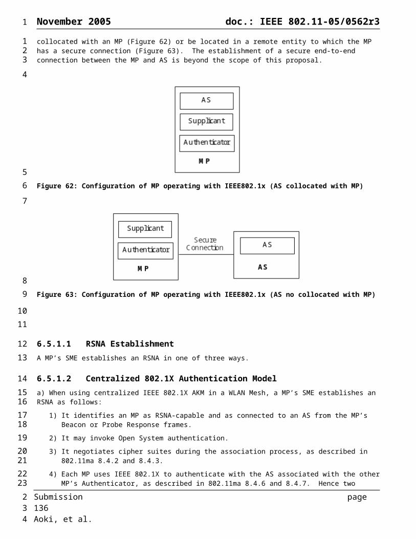
November 2005 doc.: IEEE 802.11-05/0562r3
A.2 Radio Metric AODV Algorithm Flowchart
Figure 78: Flowchart for processing a RREQ
Submission page 136 Aoki, et al.
1
123
45
67
2
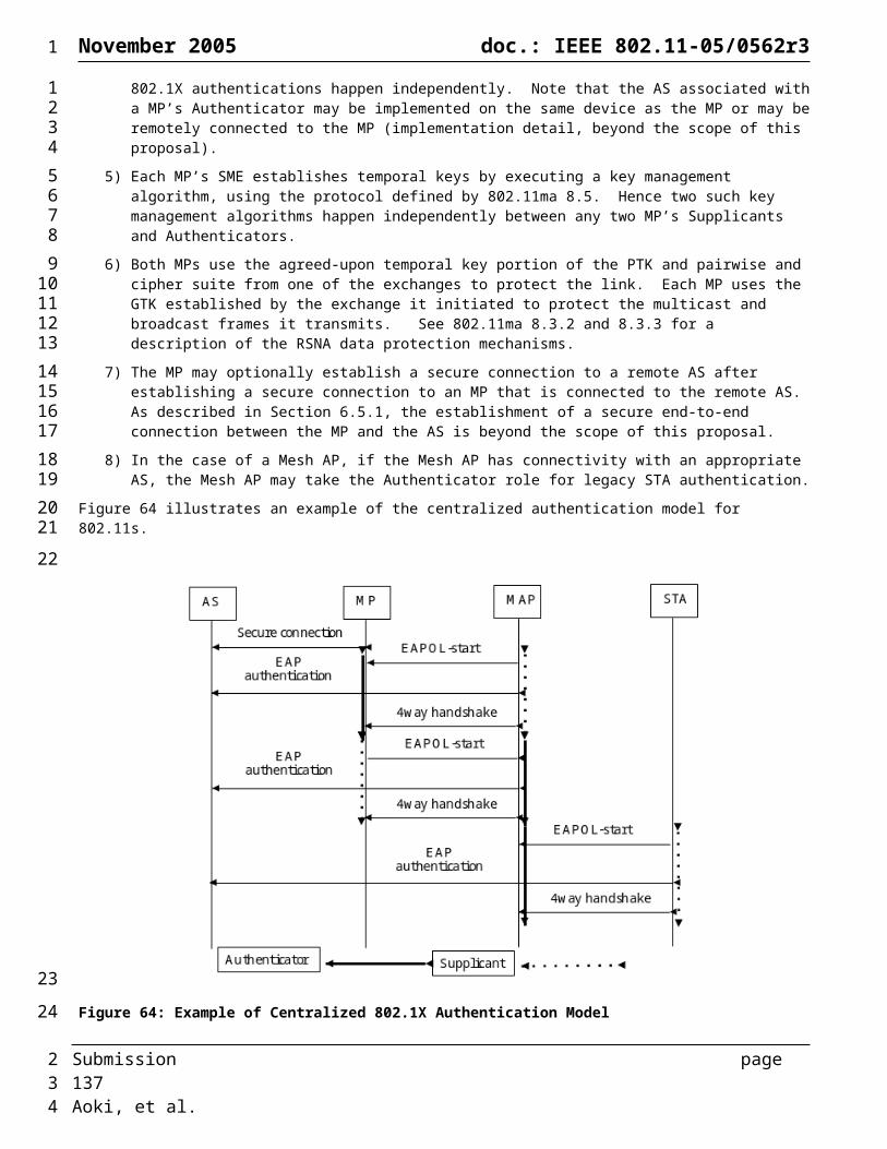
November 2005 doc.: IEEE 802.11-05/0562r3
Figure 79: Flowchart for processing expiry of a RREQ wait alarm
Submission page 137 Aoki, et al.
1
12
3
2
November 2005 doc.: IEEE 802.11-05/0562r3
Figure 80: Flowchart for processing a RREP
Submission page 138 Aoki, et al.
1
12
345678
2

November 2005 doc.: IEEE 802.11-05/0562r3
A.3 Recommended Default Values
HWMP_RREQ_REFRESH_PERIOD = 15 secondsHWMP_ROUTE_LOSS_THRESHOLD = 2HWMP_ACTIVE_ROUTE_TIMEOUT = 5000 millisecondsHWMP_RREQ_RATELIMIT = 2 HWMP_NET_DIAMETER = 20HWMP_NODE_TRAVERSAL_TIME = 40 millisecondsHWMP_NETDIAMTER_TRAVERSAL_TIME = (HWMP_NET_DIAMETER*HWMP_NODE_TRAVERSAL_TIME)HWMP_RT_NETDIAMETER_TRAVERSAL_TIME = (2*HWMP_NETDIAMTER_TRAVERSAL_TIME)HWMP_MAX_RREQ_RETRIES = 3
Submission page 139 Aoki, et al.
1
123456789
10111213
2

November 2005 doc.: IEEE 802.11-05/0562r3
Appendix B Radio Aware OLSR Flowcharts
Figure 81: Flowchart for processing an RA-OLSR routing message.
Submission page 140 Aoki, et al.
1
12
34
5
2
November 2005 doc.: IEEE 802.11-05/0562r3
Figure 82: Flowchart for processing a HELLO message.
Submission page 141 Aoki, et al.
1
12
3
4
2
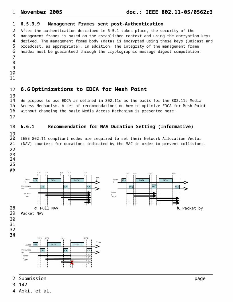
November 2005 doc.: IEEE 802.11-05/0562r3
Figure 83: Flowcharts for processing an MID message.
Figure 84: Flowcharts for processing a TC message.
Submission page 142 Aoki, et al.
1
12
3
4
56
7
2

November 2005 doc.: IEEE 802.11-05/0562r3
Figure 85: Flowchart for processing LABA message.
Submission page 143 Aoki, et al.
1
12
3
2
November 2005 doc.: IEEE 802.11-05/0562r3
Figure 86: Flowcharts for processing an LABCA message.
Figure 87: Flowcharts for processing an ABBR message.
Submission page 144 Aoki, et al.
1
12
3
45
67
8
2
November 2005 doc.: IEEE 802.11-05/0562r3
Input: STU frameInit: n = 0
START
STU.src is in node list?
lsu = STU.lsu[n]
lsu.head is in TG?
lsu.tail is in TG?
STU.length > n*sizeof(LSU)?
link(head, tail) is in TG?
lsu.timestamp > link(head,
tail).timestamp?
Update link(head, tail).timestamp and
link(head, tail).link_cost in TG
link(head, tail) is in TG(STU.src)?
lsu.timestamp > link(head,
tail).timestamp?
Update link(head, tail).timestamp and
link(head, tail).link_cost in TG(STU.src)
incr n
n > 0?
Build newSTBuild newST(STU.src)
Compare TG.ST and newST accdg to prevailing
ORA/LORA rules
ST changes need to be sent?
Build and transmit STU
TG.ST = newSTTG(STU.src).ST = newST(STU.src)
END
Yes
No
Yes
Yes
Add lsu.head to TG
Add lsu.tail to TG
Add STU.src to TG
Add link(head, tail) to TG(STU.src)
Add link(head, tail) to TG
Yes
Yes
Yes
Yes
Yes
Yes
Yes
No
No
No
No
No
No
No
No
No
Figure 88: Flowchart for processing an optional STU message.
Submission page 145 Aoki, et al.
1
12
3
45
2

November 2005 doc.: IEEE 802.11-05/0562r3
Figure 89: Flowchart for selection of MPRs.
Submission page 146 Aoki, et al.
1
12
3
2
November 2005 doc.: IEEE 802.11-05/0562r3
Figure 90: Flowchart for selection of optimal routes.
Submission page 147 Aoki, et al.
1
12
3
4
2

November 2005 doc.: IEEE 802.11-05/0562r3
Appendix C Co-located Mesh Point and Station functionality
The architecture and scenarios presented in this document introduce additional services in the IEEE 802.11 environment that enable generalized multi-hop wireless networks. Mesh services introduce a logical MAC interface that is independent of the legacy 802.11 MAC interface. Any devices that support mesh services are Mesh Points (MPs). In a particular device the mesh interface and the legacy BSS interface may be independently and individually invoked. This allows for devices that are both legacy APs and mesh points, or both legacy STAs and mesh points. The operation of mesh APs or MAPs, the APs with a mesh interface, has a significant bearing on the definition of mesh services, and is described in the document. On the other hand, the operation of devices that are STAs and MPs at the same time does not have any bearing on the standard specification. A brief description of such implementation specific operation is described in this appendix.
A special type of mesh point may be referred to as a mesh point station (MPS). Such a device has a separate logical MAC interface that functions as a STA, along with a logical MAC interface that functions as a MP. The internal communication between STA and MP interface are implementation dependent. However, given that STAs are end user client devices, bridging functionality within the IEEE 802 domain is not expected. A usage scenario for a mesh point station is shown in Figure 91. In Figure 91, the MPS is connected to two logical networks. The station interface connects it to a wired distribution system, and the mesh interface connects it to a mesh. Such a scenario may be useful, for example, if connectivity is expected with different security profiles. One interface may be secure (for example the STA interface in Figure 91), while the other (for example the mesh interface in the figure) may allow insecure access to limited services.
Figure 91: An example usage scenario for a mesh point station (MPS) with both the MP and the STA logical interfaces
Appendix D Interworking Support Example and Flowcharts
D.1 An ExampleConsider the network in Figure 92 consisting of two wired LAN segments connected by a wireless Mesh. Nodes 1 through 11 make up the Mesh. MPPs A and B act as transparent layer-2 bridges. We assume that AODV is used for unicast route discovery.
Submission page 148 Aoki, et al.
Rest of the Mesh
Network
Wired distribution system
AP
MPS
STA logical interface
MP logical interface
1
123456789
1011
12131415161718192021
2223
242526
27282930
2

November 2005 doc.: IEEE 802.11-05/0562r3
59
710
6
2
1
4
3
8
11
B
A
13
14
12
Figure 92: An example bridged network containing two wired segments and a wireless Mesh.
If node 11 wants to send a message to node 6, it looks in its route table, and finding no route, it initiates a route request. Eventually a route reply propagates back through the network, filling in route table entries along a path between 11 and 6. It is likely that the route request will be received by MPPs A and B, which will add node 11 to their bridging tables. It is also possible that the route reply will be overheard by MPP A, in which case bridge table entries will be added for all nodes in the route. Once the route reply reaches node 11, data packets can be unicast from node 11 to node 6.
If node 14 sends a packet to node 2, it will be promiscuously received by MPP B, which is acting as a transparent bridge. MPP B will look in its routing table, and finding no entry, it initiates a route request for node 2. As before, node A will receive the route request and learn that node B is in the Mesh. Eventually, node 2 will receive the route request and generate a route reply. The route reply will propagate back to MPP B, creating route entries at nodes along the path. MPP B will also create bridge entries for node 2 and the nodes along the path. Subsequent packets received by MPP B to node 2 will use this route.
If node 3 sends a packet to node 12, it will create a route request. Nodes A and B will receive the route request and add node 12 to their bridging tables. Ultimately, the route request will timeout, and node 3 will add an entry to its routing table for node 12 containing the broadcast address as the next hop. Data packets will then be sent via flood, with node 12 as the ultimate destination. When MPPs A and B receive the flood, they will repeat the packet on their wired LANs, allowing node 12 to receive the packet. Eventually, node 12 will send a packet to node 3 (most application protocols are bidirectional), allowing MPP A to learn that node 12 is on its wired LAN. MPP A will flood a portal update add message over the Mesh, allowing all nodes to learn that MPP A is the correct MPP for node 12 (by adding an entry to their routing tables). [Note that the route request sent by node A for node 3 to deliver the packet for node 12 could also allow nodes to learn that MPP A is the right way to get to node 12, eliminating the need for the portal update flood.] Subsequent packets from node 3 to node 12 will be unicast. Node 3 would look in its routing table for node 12 and find MPP A. It would then generate a route request for node A, eventually establishing a route. At this point, all nodes along the path from node 3 to MPP A know that MPP A is the right way to reach node 12, and they know the correct next hop to reach A. Thus, each node can forward a unicast packet with 12 as the ultimate destination and the appropriate next hop to node A.
D.2 Interworking Support Flowcharts
Submission page 149 Aoki, et al.
1
1
2
34567
89
10111213
14151617181920212223242526
27
2829
2
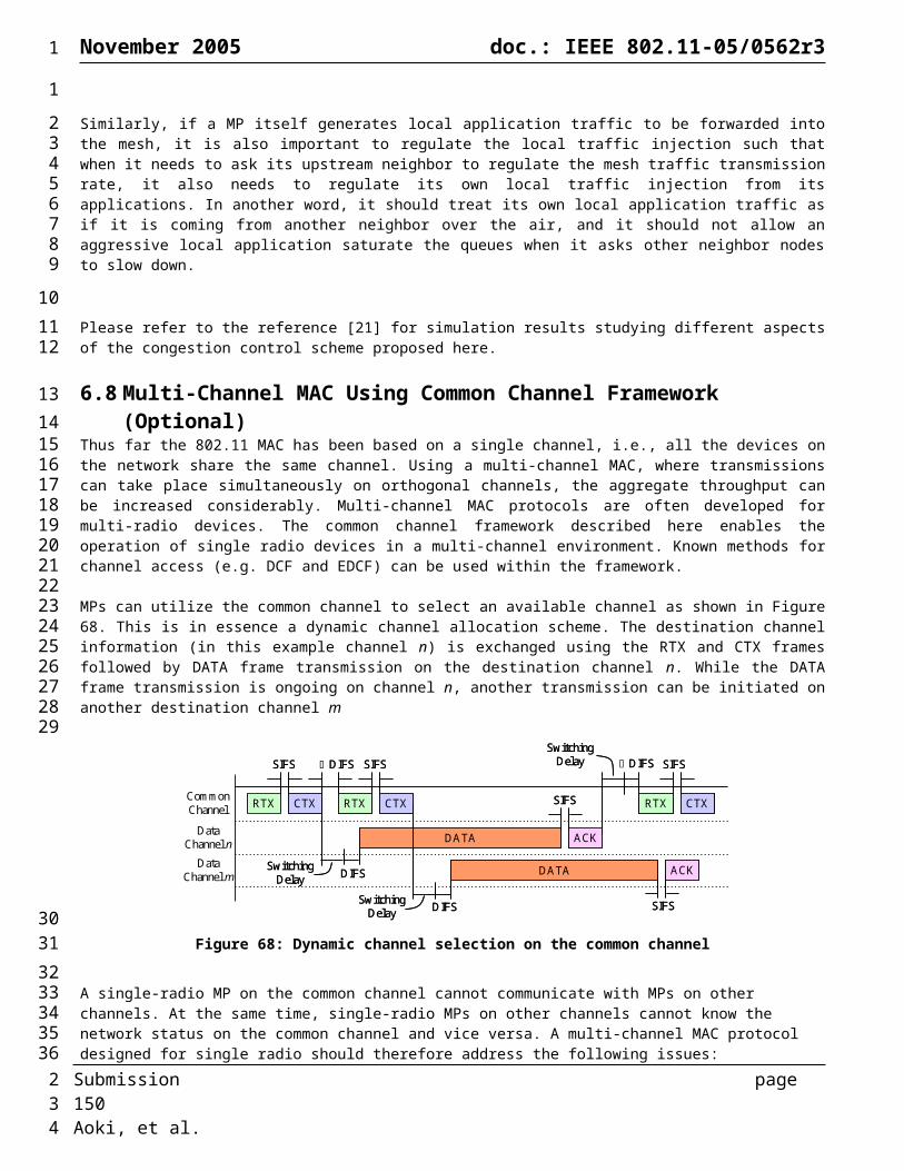
November 2005 doc.: IEEE 802.11-05/0562r3
Start
Destination?
Add/update bridging entry associated
with source address
Deliver packet locally
Destination in bridging table?
Forward packet viaall bridge ports
Bridging entry identifies mesh
port?
Packetreceived via flood to
all portals?
Packetreceived via mesh
port?
Execute Mesh forwarding process
Drop packet
Transmit add message
Forward packet viaOutbound port
YES
NO
NO
NO
NO
NO
YES
YES
YES
YES
Figure 93: The unicast packet forwarding procedure for MPPs.
Start
Destination? Deliver packet locally
Destination inrouting table?
Initiate route discoveryfor destination
Portal type entry?
Mesh type entry?
Route found? Forward packet to all portals (flood)
Insert next hop fordestination in routing
table
Set next hop ofpacket to next hop
to destination
YES
NO
NO
NO
NO
NO
YES
YES
YES
YES
Forward packet viaunicast delivery
Forward packet to all portals (flood)
Entry forportal in routing
table?
Initiate route discoveryfor portal
Discovered portal node?
Insert next hopfor portal in routing
table
Set next hop ofpacket to next hop
to portal
NO
NO
YES
Figure 94: The
unicast packet forwarding procedure for Mesh nodes with reactive routing.
Submission page 150 Aoki, et al.
1
12
34
5
6
2

November 2005 doc.: IEEE 802.11-05/0562r3
Figure 95: The unicast packet forwarding procedure for Mesh nodes with proactive routing..
Submission page 151 Aoki, et al.
Start
Destination? Deliver packet locally
Destination inrouting table?
Portal type entry? Forward packet to all portals (flood)
Set next hop ofpacket to next hop
to destination
YES
NO
NO
NO
NO
YES
YES
Forward packet viaunicast delivery
Entry forportal in routing
table?
Set next hop ofpacket to next hop
to portal
1
1
2