DIVISION 22 PLUMBING DESIGN CRITERIA …UC DAVIS Campus Design Guide PLUMBING – DIVISION 22 6 July...
16
UC DAVIS Campus Design Guide PLUMBING – DIVISION 22 1 July 2018 DIVISION 22 – PLUMBING DESIGN CRITERIA See Part II for additional information regarding Energy and Water Efficiency, etc. SYSTEMS DEFINITION Campus is served by three water distribution systems; potable, non-potable and agricultural water. The potable water is identified as the Campus Domestic Water Distribution System. This system serves the building domestic water, building industrial water and Campus fire water. AGRICULTURAL WATER The Agricultural Water Distribution system is designated as AG Water. This system is non- potable and has a dedicated piping distribution system serving the West Campus agricultural fields. UTILITY WATER The non-potable water supply system is designated as the Utility Water Distribution System and is primarily use for landscape irrigation. This system has a dedicated piping distribution system serving the main Campus only. BUILDING DOMESTIC WATER This system is used to provide for consumption and sanitary needs, industrial water needs, make- up water for mechanical system, and process water needs (i.e. DI, RO, etc.). The building domestic water service shall provide the following: 1. Refer to Division 33 for requirements for reduced pressure backflow prevention devices (RPBP) and strainers. 2. After the backflow device, a water conditioning device using a modulating frequency wave form shall be installed. Scale Blaster, or equal, no known equal. Depending on the size of the system, it is possible more than one device may be needed, particularly at hot water heat exchangers where scale tends to build up. The conditioning system type shall be discussed with the University’s Representative early in the design process before implementing a technology. 3. Perform water pressure calculations to determine the need for a domestic water booster pump. If needed, water booster pumps shall be controlled with VFDs and have pressure transducers. 4. Incoming domestic water shall be plumbed with injector fittings for water system chlorination testing. FIRE WATER This system utilizes domestic water for fire protection systems, including fire hydrants and sprinkler systems. BUILDING INDUSTRIAL WATER A building’s industrial water system is a branch of domestic water system and serves mainly laboratory spaces and fixtures. Industrial water is generated by installing reduced pressure
Transcript of DIVISION 22 PLUMBING DESIGN CRITERIA …UC DAVIS Campus Design Guide PLUMBING – DIVISION 22 6 July...

UC DAVIS Campus Design Guide
PLUMBING – DIVISION 22 1
July 2018
DIVISION 22 – PLUMBING
DESIGN CRITERIA
See Part II for additional information regarding Energy and Water Efficiency, etc.
SYSTEMS DEFINITION
Campus is served by three water distribution systems; potable, non-potable and agricultural
water. The potable water is identified as the Campus Domestic Water Distribution System. This
system serves the building domestic water, building industrial water and Campus fire water.
AGRICULTURAL WATER
The Agricultural Water Distribution system is designated as AG Water. This system is non-
potable and has a dedicated piping distribution system serving the West Campus agricultural
fields.
UTILITY WATER
The non-potable water supply system is designated as the Utility Water Distribution System and
is primarily use for landscape irrigation. This system has a dedicated piping distribution system
serving the main Campus only.
BUILDING DOMESTIC WATER
This system is used to provide for consumption and sanitary needs, industrial water needs, make-
up water for mechanical system, and process water needs (i.e. DI, RO, etc.).
The building domestic water service shall provide the following:
1. Refer to Division 33 for requirements for reduced pressure backflow prevention devices
(RPBP) and strainers.
2. After the backflow device, a water conditioning device using a modulating frequency
wave form shall be installed. Scale Blaster, or equal, no known equal. Depending on the
size of the system, it is possible more than one device may be needed, particularly at
hot water heat exchangers where scale tends to build up. The conditioning system type
shall be discussed with the University’s Representative early in the design process
before implementing a technology.
3. Perform water pressure calculations to determine the need for a domestic water booster
pump. If needed, water booster pumps shall be controlled with VFDs and have pressure
transducers.
4. Incoming domestic water shall be plumbed with injector fittings for water system
chlorination testing.
FIRE WATER
This system utilizes domestic water for fire protection systems, including fire hydrants and
sprinkler systems.
BUILDING INDUSTRIAL WATER
A building’s industrial water system is a branch of domestic water system and serves mainly
laboratory spaces and fixtures. Industrial water is generated by installing reduced pressure

UC DAVIS Campus Design Guide
PLUMBING – DIVISION 22 2
July 2018
backflow prevention (RPBP) devices at a tee, downstream of the building domestic water RPBP.
This industrial water RPBP device is intended to protect the building occupants from labs and
other research areas or mechanical spaces. Note, additional water conditioning as described
above may be required after the RPBP. See section 22 67 00 Processed Water for Laboratory
Facilities.
CARBON FILTERED WATER
Carbon filters are filled with activated carbon, and can be regenerated by a backwash cycle.
Carbon filters shall be equipped with an electro mechanical metered Fleck valve, or equal.
Carbon filters remove in-organic material (manmade) elements such as pesticides and chlorine. It
is important to remove these elements upstream of the reverse osmosis system (RO), because
these elements quickly destroy the RO membrane.
SOFTENED WATER
Soft water is water that is treated by ion exchange within the softener. Elements such as iron,
calcium, and magnesium are removed by ion exchange and replaced with sodium ions. This
results in a slightly higher TDS. (From 360 TDS – 380 TDS) Water softeners shall be equipped
with an electro–mechanical metered Fleck valve, or equal. (See Applied Membranes softeners)
REVERSE OSMOSIS (RO) WATER
Reverse osmosis is a filtration method that removes particles by passing water across a
semipermeable membrane. During the RO process, 95 – 99 percent of all dissolved solids and
bacteria are removed. Most RO systems on campus are set at a 50 percent recovery rate, but
can somewhat be adjusted to waste less water at the risk of reducing the life of the RO
membrane. The water produced has 1-3ppm and is approximately ½ megohm in quality.
DEIONIZED (DI) WATER
Deionized water results from a filtration method which removes the electrically charged atoms
and molecules by passing water through ion exchange resins. The Campus uses mixed bed resin
beads in the ion exchange DI bottles, which exchanges elements such as potassium, aluminum,
manganese, etc., for hydrogen and hydroxide ions to form pure H2O. In non-circulating systems,
2-10 megohm water is produced. In circulating loop systems with ultra-violet and high purity
filters, purity can be as high as 18.3 megohm.
SANITARY SEWER
The Campus wastewater treatment system consists of the treatment plant, pumping stations, and
the collection piping network. The entire sanitary sewer system flows into pumps and sewage is
mechanically pumped to the treatment facility.
COMMON REQUIREMENTS 22 05 13
GENERAL REQUIREMENTS
1. Piping shall not be installed in, pass through, or enter the telecommunications room,
except as needed to serve the room itself.
2. Piping shall not be installed above electrical panelboards, switchboards, switchgear,
transformers, or safety disconnect switches.
2. See Section 23 05 13 in Division 23 for motor requirements.
3. Section Zone Valves: Union ball valves.

UC DAVIS Campus Design Guide
PLUMBING – DIVISION 22 3
July 2018
4. Pressure Gauges: Pressure or vacuum type as required.
5. Gas Outlets: See Vacuum System requirements above.
6. Fuel Gas: Lubricated plug cock.
7. For maintenance and access requirements, refer to Part II Design Requirements,
‘Access’.
METERS & GAGES FOR PLUMBING PIPING 22 05 19
Refer to the University’s Standard Specification, Section 33 12 33, Water Utility Metering, for
metering requirements.
PLUMBING VALVES 22 05 23
A. General Requirements:
1. Valves shall be located in readily accessible areas.
2. Valves that are concealed are to be accessible via clearly marked access panels
when located above or behind new or existing finished surfaces. Access panels shall
be a minimum of 12 inches by 12 inches, or as needed for maintenance access.
3. Each laboratory room shall have dedicated shut off valves.
B. General Purpose Shut-off Valves:
1. Performance Requirements: 2-piece, brass body, brass ball, brass stem with Teflon
seats, threaded or flanged connection (depending on application)
2. Products: Apollo, Milwaukee Hammond or equal.
C. Pressure Reducing Valves:
1. Performance Requirements: All brass, Teflon disc and diaphragm for hot water
service
2. Products: Watts, Wilkins, or equal.
D. Fixture Shut-off Valves:
1. Performance Requirements: All brass, quarter turn angle stops, threaded only
2. Products: Brass Craft or equal
E. Check Valves:
1. Performance Requirements: All brass swing check or 1/2 lb. spring check type,
threaded or flanged connection (depending on application).
2. Products: Apollo, Milwaukee Hammond or equal.
F. Bench Valves: Ball type with tapered sockets with ball and seat compatible with piping
material.
G. Laboratory Valves (air, gas, vacuum):
1. Performance Requirements:
a. Laboratory grade with forged brass lever handles
b. Rotating chrome plated brass ball and molded RFE seals
c. Rated for use up to 75 psi
2. Products: Water Saver, Chicago, T&S Brass, or equal
UC DAVIS Campus Design Guide
PLUMBING – DIVISION 22 4
July 2018
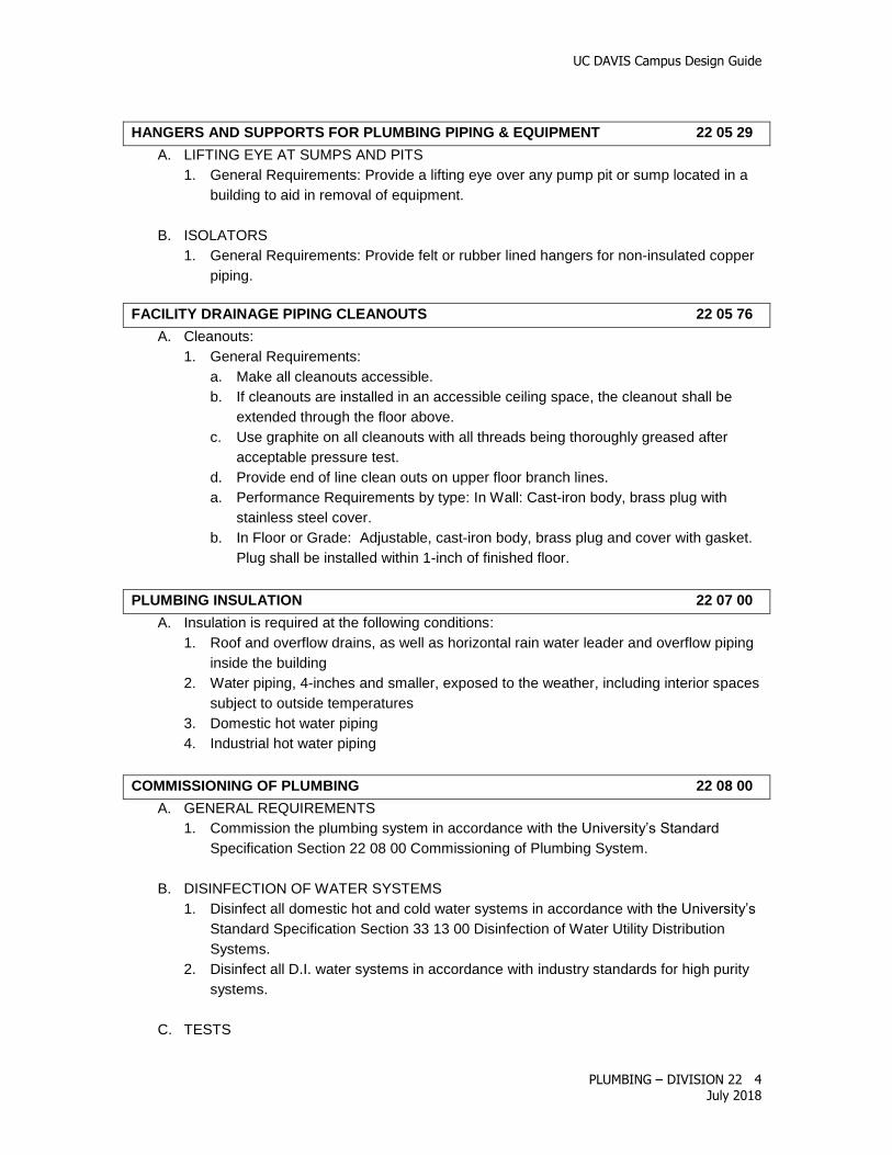
HANGERS AND SUPPORTS FOR PLUMBING PIPING & EQUIPMENT 22 05 29
A. LIFTING EYE AT SUMPS AND PITS
1. General Requirements: Provide a lifting eye over any pump pit or sump located in a
building to aid in removal of equipment.
B. ISOLATORS
1. General Requirements: Provide felt or rubber lined hangers for non-insulated copper
piping.
FACILITY DRAINAGE PIPING CLEANOUTS 22 05 76
A. Cleanouts:
1. General Requirements:
a. Make all cleanouts accessible.
b. If cleanouts are installed in an accessible ceiling space, the cleanout shall be
extended through the floor above.
c. Use graphite on all cleanouts with all threads being thoroughly greased after
acceptable pressure test.
d. Provide end of line clean outs on upper floor branch lines.
a. Performance Requirements by type: In Wall: Cast-iron body, brass plug with
stainless steel cover.
b. In Floor or Grade: Adjustable, cast-iron body, brass plug and cover with gasket.
Plug shall be installed within 1-inch of finished floor.
PLUMBING INSULATION 22 07 00
A. Insulation is required at the following conditions:
1. Roof and overflow drains, as well as horizontal rain water leader and overflow piping
inside the building
2. Water piping, 4-inches and smaller, exposed to the weather, including interior spaces
subject to outside temperatures
3. Domestic hot water piping
4. Industrial hot water piping
COMMISSIONING OF PLUMBING 22 08 00
A. GENERAL REQUIREMENTS
1. Commission the plumbing system in accordance with the University’s Standard
Specification Section 22 08 00 Commissioning of Plumbing System.
B. DISINFECTION OF WATER SYSTEMS
1. Disinfect all domestic hot and cold water systems in accordance with the University’s
Standard Specification Section 33 13 00 Disinfection of Water Utility Distribution
Systems.
2. Disinfect all D.I. water systems in accordance with industry standards for high purity
systems.
C. TESTS

UC DAVIS Campus Design Guide
PLUMBING – DIVISION 22 5
July 2018
1. Test only new piping.
2. Final connection between new and existing piping shall be tested at normal system
operating pressures.
3. Make no test against a service valve or meter.
4. Isolate from the system all existing piping systems and new or existing equipment
which may be damaged by test pressure. No loss in pressure or visible leaks shall
show after 4 hours at the pressures indicated:
System Tested Test Pressure PSI Test with Sanitary &
Lab
Sanitary and Lab, Waste, Drain, Vent 10 ft. head Water
Compressed Air 150 PSI Air & Soap
Deionized Water 100 PSI Deionized Water
Industrial and Domestic Hot & Cold Water 150 PSI* Water
Medical Gas 110 PSI Air & Soap
Natural Gas p.c. 1204.3.2 Low Pres: 10 PSI/15 min.
Med Pres: 60 PSI/30 min.
Vacuum 110 PSI 27 inch vac. Air & Soap
*or 1.5 times the operational pressure, whichever is higher
DOMESTIC WATER DISTRIBUTION 22 11 00
A. General Requirements
1. The building plumbing systems shall have appropriate shut off valve zoning to allow
for ease of maintenance with minimal shutdown impact to building occupants.
2. At minimum, shut off valves shall be provided for the following: each floor, each toilet
room, each laboratory room, each equipment room, and each kitchen.
B. Piping
1. Above and below grade: Type L copper tubing
a. 1-1/2 inches and below: soft drawn
b. 2 inches and above: hard temper, cold drawn
C. Joints
1. All above grade piping, 2 inches and larger, and all below grade piping, regardless of
size, shall be brazed with silver solder (silver/phosphorus).
D. Fittings
1. Copper tubing: Wrought copper or cast brass solder sweat type.
E. Unions and Flanges
1. General Requirements:
a. Unions and flanges shall be provided at the inlet and outlet of all apparatus and
equipment, at all valves, and elsewhere as required to facilitate removal of valves
and equipment.
b. Flexible lines shall not be used in laboratories.
c. When connecting dissimilar metals, use brass nipples. Do not use devices with
plastic components in contact with the flow stream.
UC DAVIS Campus Design Guide
PLUMBING – DIVISION 22 6
July 2018
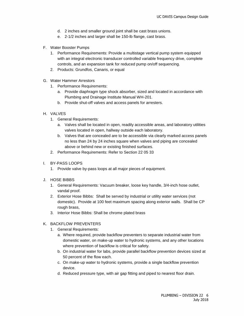
d. 2 inches and smaller ground joint shall be cast brass unions.
e. 2-1/2 inches and larger shall be 150-lb flange, cast brass.
F. Water Booster Pumps
1. Performance Requirements: Provide a multistage vertical pump system equipped
with an integral electronic transducer controlled variable frequency drive, complete
controls, and an expansion tank for reduced pump on/off sequencing.
2. Products: Grundfos, Canaris, or equal
G. Water Hammer Arrestors
1. Performance Requirements:
a. Provide diaphragm type shock absorber, sized and located in accordance with
Plumbing and Drainage Institute Manual WH-201.
b. Provide shut-off valves and access panels for arresters.
H. VALVES
1. General Requirements:
a. Valves shall be located in open, readily accessible areas, and laboratory utilities
valves located in open, hallway outside each laboratory.
b. Valves that are concealed are to be accessible via clearly marked access panels
no less than 24 by 24 inches square when valves and piping are concealed
above or behind new or existing finished surfaces.
2. Performance Requirements: Refer to Section 22 05 33
I. BY-PASS LOOPS
1. Provide valve by-pass loops at all major pieces of equipment.
J. HOSE BIBBS
1. General Requirements: Vacuum breaker, loose key handle, 3/4-inch hose outlet,
vandal proof.
2. Exterior Hose Bibbs: Shall be served by industrial or utility water services (not
domestic). Provide at 100 feet maximum spacing along exterior walls. Shall be CP
rough brass,
3. Interior Hose Bibbs: Shall be chrome plated brass
K. BACKFLOW PREVENTERS
1. General Requirements:
a. Where required, provide backflow preventers to separate industrial water from
domestic water, on make-up water to hydronic systems, and any other locations
where prevention of backflow is critical for safety.
b. On industrial water for labs, provide parallel backflow prevention devices sized at
50 percent of the flow each.
c. On make-up water to hydronic systems, provide a single backflow prevention
device.
d. Reduced pressure type, with air gap fitting and piped to nearest floor drain.

UC DAVIS Campus Design Guide
PLUMBING – DIVISION 22 7
July 2018
e. Backflow prevention devices shall be located for easy access for maintenance.
They shall not be installed higher than 5-feet above the finished floor, in ceilings,
or in concealed spaces.
FACILITY SANITARY SEWERAGE 22 13 00
A. General Requirements:
1. All toilet rooms, laundry rooms and first floor trash rooms shall have floor drains.
2. Sewer lines at toilet room vanities shall be designed properly with sweeps rather than
“Ts” to allow for snaking when blockage occurs.
3. No reducing couplings allowed.
4. All floor drains shall be equipped with automatic trap priming systems.
B. Piping:
1. General Requirements:
a. Service weight cast iron
b. Above or underground no hub waste piping must use 4-band couplings
c. No hub waste vent piping may utilize 2-band couplings
2. Underground piping: no-hub or hub & spigot joined with compression gaskets.
3. Above ground piping:
a. >2 inch no-hub with stainless steel and neoprene coupling.
b. <2 inch no-hub with stainless steel and neoprene couplings, or schedule 40
galvanized steel pipe joined with Durham type threaded drainage fittings.
C. Sanitary Sewer Ejector:
1. General Requirements: Flow controls set as individually operated; provide units
without chopper blades; units shall be counter-balanced.
FACILITY STORM DRAINAGE 22 14 00
A. General Requirements:
1. Roof and overflow drains shall be piped independently to outside.
2. Overflow drain piping shall be day-lighted through exterior wall, minimum 18-inches
above grade.
B. Piping: Same as above Section 22 13 00 - Facility Sanitary Sewerage.
C. Drains:
1. General Requirements: cast iron, unless otherwise noted.
2. Types:
a. Area drain: Cast iron top
b. Roof and overflow drains: Cast iron with flange, flashing ring, gravel stop,
underdeck clamp, extension, sump receiver, dome strainer, vandal proof,
standpipe (overflow only).
c. Floor drain: Cast iron body, N.B. top, with sediment bucket.
UC DAVIS Campus Design Guide
PLUMBING – DIVISION 22 8
July 2018
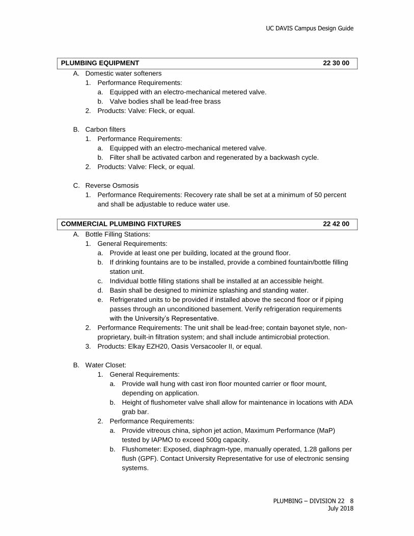
PLUMBING EQUIPMENT 22 30 00
A. Domestic water softeners
1. Performance Requirements:
a. Equipped with an electro-mechanical metered valve.
b. Valve bodies shall be lead-free brass
2. Products: Valve: Fleck, or equal.
B. Carbon filters
1. Performance Requirements:
a. Equipped with an electro-mechanical metered valve.
b. Filter shall be activated carbon and regenerated by a backwash cycle.
2. Products: Valve: Fleck, or equal.
C. Reverse Osmosis
1. Performance Requirements: Recovery rate shall be set at a minimum of 50 percent
and shall be adjustable to reduce water use.
COMMERCIAL PLUMBING FIXTURES 22 42 00
A. Bottle Filling Stations:
1. General Requirements:
a. Provide at least one per building, located at the ground floor.
b. If drinking fountains are to be installed, provide a combined fountain/bottle filling
station unit.
c. Individual bottle filling stations shall be installed at an accessible height.
d. Basin shall be designed to minimize splashing and standing water.
e. Refrigerated units to be provided if installed above the second floor or if piping
passes through an unconditioned basement. Verify refrigeration requirements
with the University’s Representative.
2. Performance Requirements: The unit shall be lead-free; contain bayonet style, non-
proprietary, built-in filtration system; and shall include antimicrobial protection.
3. Products: Elkay EZH20, Oasis Versacooler II, or equal.
B. Water Closet:
1. General Requirements:
a. Provide wall hung with cast iron floor mounted carrier or floor mount,
depending on application.
b. Height of flushometer valve shall allow for maintenance in locations with ADA
grab bar.
2. Performance Requirements:
a. Provide vitreous china, siphon jet action, Maximum Performance (MaP)
tested by IAPMO to exceed 500g capacity.
b. Flushometer: Exposed, diaphragm-type, manually operated, 1.28 gallons per
flush (GPF). Contact University Representative for use of electronic sensing
systems.

UC DAVIS Campus Design Guide
PLUMBING – DIVISION 22 9
July 2018
c. Seat: White, heavy-duty, commercial type, elongated, open front, solid
plastic, with stainless steel hinge.
3. Products:
a. Water closet: American Standard, , or equal
b. Flushometer: Zurn, Sloan, or equal
C. Urinals
1. General Requirements:
a. Urinals shall be accessible.
b. For renovations, existing piping network shall be evaluated for size and slope.
2. Performance Requirements:
a. Wall hung, ultra-low flow 0.125 GPF, vitreous white china with in wall carrier
b. Side discharge units are not acceptable.
c. Flushometer: Exposed, diaphragm-type, manually operated, ultra-low flow 0.125
GPF. Contact University Representative for use of electronic sensing systems.
3. Products: Zurn, Sloan, or equal
D. Wall-hung lavatory:
1. General Requirements: Visible traps should be chrome plated unless the project
requires special finishes.
2. Performance Requirements:
a. 4-inch center vitreous china, with concealed carrier arm
b. Sanitary waste traps for equipment shall be “P” type, 17 gauge, cast brass, slip
joint nuts, chrome-plated brass escutcheons, and cleanout plug.
3. Products: American Standard, , or equal
4. Faucet: Manually operated, single control center set, 0.5 gpm, vandal resistant,
pressure compensating multi-laminar spray. Contact University for use of electronic
sensing systems.
E. Sink, general purpose:
1. Performance Requirements:
a. 18 gauge, type 304 stainless steel sink; 17 gauge chrome plated 1-1/2 inch by 1-
1/2 inch trap
b. Deck mounted low flow faucet, lever handle, gooseneck, rigid spout plain outlet.
2. Products: Elkay, Just, or equal.
F. Shower Valve
1. Performance Requirements:
i. Pressure balancing, four port, quarter turn stops.
2. Products: Moen, or equal.
G. Laboratory sinks, general purpose:
1. Performance Requirements:
a. Epoxy resin, under-counter mount, chemical resistant
b. Faucet: Deck-mounted, gooseneck spout, replaceable stainless steel seats, built
in stops; self-closing for D.I. applications
3. Products:

UC DAVIS Campus Design Guide
PLUMBING – DIVISION 22 10
July 2018
a. Sink: Durcon or equal
b. Faucet: Water Saver, Chicago, or equal.
H. Laboratory Sinks used for dry ice disposal:
1. General Requirements: Provide one per laboratory
2. Performance Requirements:
a. Sink: 18 gauge, type 304 stainless steel
b. Faucet: Deck-mounted, gooseneck spout, replaceable stainless steel seats, built
in stops
3. Products:
a. Sink: Elkay, Just, or equal
b. Faucet: Water Saver, Chicago, or equal.
I. Drain: 1-1/2 inch tailpiece, grid strainer.
EMERGENCY PLUMBING FIXTURES 22 45 00
A. Emergency Plumbing Fixtures (eyewash units and showers)
1. General Requirements:
a. Supplied by domestic water.
b. Readily visible and accessible to the laboratory or work site. The unit should be
located as close to the hazard as possible and cannot be blocked by building
structures, cabinets, supplies or equipment.
c. Provided with an activation device, such as stay open ball valve, that allows the
user full movement of both hands after the valve is turned on.
d. Identified with a highly visible sign.
e. Drain shall be plumbed to sanitary sewer.
f. Located so as not to pose an electrical shock hazard. No electrical outlets within
6 feet unless GFI protected.
g. Indoor units are not required to deliver tempered water.
2. Performance Requirements: Shall meet the performance and installation
requirements of the American National Standards Institute (ANSI) Z358.1.
B. Emergency eye wash:
1. General Requirements:
a. Each laboratory using substances described below shall provide one emergency
eye or eye/facewash located as close as possible to the hazard.
1. Shall be provided in all work areas where, during routine operations of
foreseeable emergencies, the eyes of an employee may come in contact with
a substance which can cause corrosion, severe irritation or permanent tissue
damage, or which is toxic by absorption.
2. Shall be provided if there will be processes that produce flying particles,
including sawdust, metal shavings, biological agents, etc.
b. Consult the University’s Representative for selection of the appropriate type(s)
from the following:
1. For laboratory units installed at sinks, provide eyewash unit which swings
spray head assembly over sink activating continuous flow of water.

UC DAVIS Campus Design Guide
PLUMBING – DIVISION 22 11
July 2018
2. For Barrier Free units, provide wall-mounted, low-profile eyewash with plastic
receptor and aluminum wall bracket.
3. For recessed units, provide swing down eyewash in a fully recessed wall
mounted stainless steel cabinet with drain pan.
4. Hand held drench hoses are not considered eyewash units. They may be
used in addition to equipment, which is described as meeting the ANSI
standard above. In some cases, a sink-mounted eyewash and a drench
hose may be installed in lieu of a combination eyewash/safety shower.
Consult the University’s Representative for coordination with UCD EH&S for
review and approval of this configuration.
c. Mounted such that the water nozzles are 33 inches to 45 inches from the floor
level and spray head height shall be below 36-inches and 17 to 25-inches from
bowl edge, wall, or obstruction; height should comply with Americans with
Disabilities Act of 1990 (ADA) requirements and at least 34-inches of clearance
around the eyewash must be maintained.
d. Mounted such that spray nozzles, when activated, are no more than 18 inches
from the counter front when located above work counters or benches.
e. Drain shall be plumbed to sanitary sewer.
2. Performance Requirements:
a. Regulated to provide a spray force of three to six gallons per minute at 30 psi.
3. Products: Haws, WaterSaver, or equal
C. Emergency showers:
1. General Requirements:
a. Emergency shower with integral eyewash unit is required if during routine
operations there is a risk of a splash of corrosive or other skin hazardous
material to the body.
b. Units shall be adequately supplied with potable water to meet the requirements
of each component.
c. A combination eyewash/emergency shower shall be located within a research
laboratory using hazardous chemicals; or a combination eyewash/emergency
shower may be located outside the laboratory provided an eyewash is located in
the laboratory. The combination unit shall be located so that travel distance is no
more than 10 seconds or 100 feet with no obstructions and only one door to pass
through to reach the unit.
d. The unit shall be installed and located so both the shower and eyewash can be
used at the same time by one person.
e. The diameter of the water pattern of the shower measured 60 inches above the
surface on which the user stands shall be a minimum of 20 inches.
f. The center of the spray pattern shall be located at least 16 inches from any
obstruction.
g. Installed such that the shower head is not less than 82 inches or more than 96
inches from the surface on which the user stands.
h. Supplied by a minimum pipe size of 1 inch.
2. Performance Requirements:
a. The shower shall be able to deliver a minimum of 30 gallons per minute.

UC DAVIS Campus Design Guide
PLUMBING – DIVISION 22 12
July 2018
3. Products: Haws 8346 or Guardian G1909 HFC (GBF1909 Barrier Free), Haws
8355WC (recessed), Guardian GBF2150 (recessed), or equal.
COMPRESSED AIR SYSTEMS FOR LABORATORY FACILITIES 22 61 00
A. Compressed air systems
1. General Requirements:
a. Identify the design and installation requirements for compressed air quality, dew
point, pressure, flow, and volume to meet project specific requirements.
b. Compressors shall be oil-type except for medical or dental applications. Refer to
CDG Section 22 63 00 for Ultra-Pure system requirements.
c. Buildings utilizing compressed air for laboratory functions and HVAC systems
shall have separate compressors.
d. Provide refrigerant dryers. In locations where refrigerant dryers cannot be used,
consult the University’s Representative. If desiccant dryers are to be used, they
shall be capable of standby mode. Desiccant dryers shall not be used in small air
compressor applications.
2. Air Compressors
a. Provide lead/lag compressors for systems requiring 10 HP compressors or
larger, i.e. split one 10 HP compressor into two 5 HP lead/lag compressors.
b. Provide inter-cooled and after cooled, 2 stage compressors/pumps for all 5 HP
systems and larger.
c. Provide
d. Provide single stage compressors only for applications requiring 100 pounds or
less.
e. Once through cooling water systems are prohibited.
3. Compressed Air Piping:
a. Above ground: Type L copper tubing, hard drawn.
b. Below ground: Type K copper tubing, hard temper, cold drawn with brazed joints.
c. Joints: Silver brazing alloy, melting point above 1000 degrees F, 15 percent
silver, 80 percent copper 5 percent phosphorous.
d. Fittings: Wrought copper or brass; solder sweat type. Couplings shall be of the
staked stop type.
e. Valves: Ball type.
f. Lab Air Outlets: Line size, Ball valve or needle valves to match project
requirements.
g. Points of connection to existing copper air piping in existing buildings shall be
screwed, soldered, or brazed, depending on system.
VACUUM SYSTEMS FOR LABORATORY FACILITIES 22 62 00
A. Vacuum Systems
1. General Requirements: Identify the design and installation requirements for vacuum,
pressure and flow to meet project specific requirements.
2. Performance Requirements:
a. Piping, Joints, Fittings, Valves, and Lab Air Outlets:

UC DAVIS Campus Design Guide
PLUMBING – DIVISION 22 13
July 2018
1. See Compressed Air System requirements above.
b. Vacuum Pump:
1. Furnish air-cooled duplex vacuum unit complete with base mounted pumps,
tank drain, flexible connection, scrubber, check valves, relief valves, control
panel including fused disconnect, vacuum switches and gauges, motors,
starters, electrical alternator.
2. NEMA rating shall be specified based on the location of equipment.
3. Vacuum Pump Products: Ingersoll-Rand, or equal.
GAS SYSTEMS FOR LABORATORY FACILITIES 22 63 00
A. Specialty Gases
1. General Requirements:
a. This section applies to laboratories that require Ultra-Pure piping system for
special gases including nitrogen, oxygen, CO2, Argon, etc.
b. Identify the design and installation requirements for quality, pressure and flow for
all specialty gasses to meet project specific requirements.
c. Grounding: All oxygen, nitrous oxide and vacuum lines shall be grounded to the
water supply system to reduce the possibility of static electric charges.
2. Performance Requirements:
a. Comply with NFPA 99 requirements for Gas and Vacuum Systems. Although this
standard applies to Health Care systems, the requirements noted in this standard
shall be applied for special lab air system.
b. Screwed Connections: Wherever possible, screwed joints made in attaching
valves, or other permanently connected equipment shall be silver brazed after
assembly using precautions to avoid overheating the valve or equipment. Where
conditions do not permit this method of assembly, the connection joints shall be
tinned or sweated with solder. No joint compound shall be used.
3. Products: Nitrogen and Argon: Plug Shutoff Valve; Circle Seal 9259 with Buna-N O-
ring, or equal (no known equal).
LABORATORY CHEMICAL WASTE AND VENT PIPING 22 66 00
A. Piping
1. Performance Requirements:
a. New construction: Schedule 40 flame retardant polypropylene pipe
b. Existing buildings with glass piping: Chemically resistant glass drain line piping
may be used for repair of material or polypropylene with adaptors.
B. Fittings
1. Performance Requirements:
a. General: fusion coil joints
b. Provide mechanical joint fittings at all piping around benches and equipment,
above ground and accessible piping, and all acid waste piping.
c. Compression fittings are not allowed.
2. Products:
a. General piping: Enfield “Enfusion” or equal in walls or ceilings

UC DAVIS Campus Design Guide
PLUMBING – DIVISION 22 14
July 2018
b. Piping around benches and equipment, under and around sinks, and in
accessible areas: Enfield, "Labline" or equal
C. Traps
1. Performance Requirements:
a. Universal: 1-1/2 inch Polypropylene clear base
b. Acid waste and fume hood sinks: drum trap with drain connection adapter and
union connection
3. Products:
a. Universal: Enfield W5115, Harrington or equal.
b. Acid waste: Nalgene 96025-1500, Sloane, or equal
D. Supports
1. Performance Requirements: Horizontal polypropylene piping shall have a continuous
16-gauge galvanized sheet metal trough support or maximum 2 foot support spacing
system.
E. Fixtures
1. Performance Requirements:
a. Funnel Sink: Cast iron, with trap and 6 inch diameter inlet.
b. Cup Sink: Polyethylene, oval with integral waste fitting, 1-1/2 inch with
polypropylene trap.
PROCESSED WATER SYSTEMS FOR LABORATORY FACILITIES 22 67 00
A. Processed water systems
1. General Requirements:
a. When program needs require specially treated water supplies (e.g., deionized
water for laboratory needs), these needs shall be met by providing on-site
treatment systems. Such systems may include carbon filters, water softeners,
reverse osmosis units, ion exchange systems, and ultraviolet light disinfection
systems with ultra-filtration. Review the project specific requirements for water
quality, quantity, pressure and flow to identify the design and installation
requirements with the University’s Representative.
b. Life-cycle costing shall be used to select system components (e.g., the use of
resin beds vs. reverse osmosis units). Consideration should also be given during
design for future needs in the facility and/or adjacent areas to allow for future
expansion of local water treatment devices to meet higher flow and/or water
quality requirements. Leased systems shall not be used to meet new facility
needs.
2. Performance Requirements:
a. Reverse Osmosis systems shall have a regenerating type of softener with
backwashing carbon filters in lieu of exchange bottles.
b. Deionized water systems shall be designed to provide for a minimum 10
megohm system unless otherwise required by the University’s Representative.
The entire DI system shall be recirculating; no ‘dead legs’.

UC DAVIS Campus Design Guide
PLUMBING – DIVISION 22 15
July 2018
B. Ultra-Pure Deionized Systems
2. Performance Requirements:
a. The system shall be recirculating through deionized polishing bottles
b. Piping, joints and fittings: Unpigmented (natural) polypropylene, copolymer Type
1, Schedule 40 butt-fusion and/or socked fusion.
c. The entire system shall be sterilized.
3. Products: For bench valves: use Chicago 828PVDF (solid PVDF valve), or equal
Table 1: Water Quality and Equipment
C. Piping, joints, fittings, and unions
1. General Requirements:
a. Metric sizes are not acceptable.
b. Supports: Piping 2 inches and smaller and all horizontal piping shall have
continuous 16-gauge galvanized sheet metal trough support or maximum 2 foot
support spacing system.
c. Sanitizing: The entire distribution loop and components shall be sanitized per the
requirements in the Specification Section 33 13 00, Disinfection of Domestic
Description Use: Quality Equipment: Piping:
Domestic
Water (DW),
plain
Consumption; fixtures Potable None Copper
Softened
Water
Process equipment,
dishwashing, cage-
washing
A minimum of
95 percent of
TDS removed
Softener Copper
Softened +
R.O.
Process equipment,
consumption, feed water
for D.I. system
5 percent or
less of TDS
and bacteria;
1-3ppm;
approx. 0.5
megohm
In addition to
above:
- Carbon Filter
- R.O. Prefilter
- R.O. System
Copper
Softened +
R.O. + D.I.
Laboratory grade for
non-critical purposes;
lab equipment
connections; Type I feed
water
Type II or III,
per ASTM
D1193-6;
verify with
University’s
Representative
In addition to
above:
- UV Sterilizers
- 0.2 micron vinyl
filter
- Mixed bed De-
Ionization bottles
- Resin Trap
- Storage Tanks
- Distribution
Pumps
Schedule 80
PVC
Softened +
R.O. + Ultra-
pure D.I.
Critical laboratory
applications; research/
medical grade
Type I, per
ASTM D1193-
6
In addition to
above:
- Polisher
Hi-purity
polypropylene
UC DAVIS Campus Design Guide
PLUMBING – DIVISION 22 16
July 2018
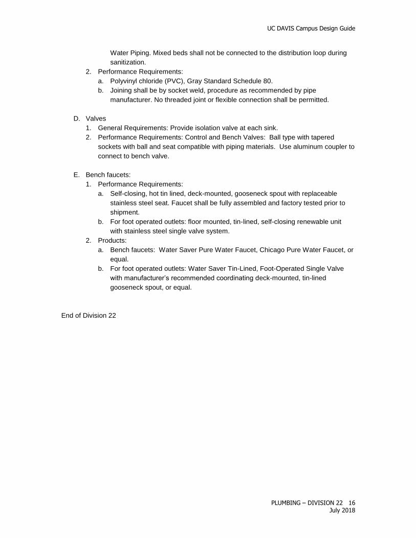
Water Piping. Mixed beds shall not be connected to the distribution loop during
sanitization.
2. Performance Requirements:
a. Polyvinyl chloride (PVC), Gray Standard Schedule 80.
b. Joining shall be by socket weld, procedure as recommended by pipe
manufacturer. No threaded joint or flexible connection shall be permitted.
D. Valves
1. General Requirements: Provide isolation valve at each sink.
2. Performance Requirements: Control and Bench Valves: Ball type with tapered
sockets with ball and seat compatible with piping materials. Use aluminum coupler to
connect to bench valve.
E. Bench faucets:
1. Performance Requirements:
a. Self-closing, hot tin lined, deck-mounted, gooseneck spout with replaceable
stainless steel seat. Faucet shall be fully assembled and factory tested prior to
shipment.
b. For foot operated outlets: floor mounted, tin-lined, self-closing renewable unit
with stainless steel single valve system.
2. Products:
a. Bench faucets: Water Saver Pure Water Faucet, Chicago Pure Water Faucet, or
equal.
b. For foot operated outlets: Water Saver Tin-Lined, Foot-Operated Single Valve
with manufacturer’s recommended coordinating deck-mounted, tin-lined
gooseneck spout, or equal.
End of Division 22