MASTER SPECIFICATIONS Division 22 PLUMBING - … · MASTER SPECIFICATIONS: DIVISION 22 ... COMMON...
235
MASTER SPECIFICATIONS Division 22 – PLUMBING Release 1.0 [March] 2017 Released by: Northwestern University Facilities Management Operations 2020 Ridge Avenue, Suite 200 Evanston, IL 60208-4301 All information within this Document is considered CONFIDENTIAL and PROPRIETARY. By receipt and use of this Document, the recipient agrees not to divulge any of the information herein and attached hereto to persons other than those within the recipients’ organization that have specific need to know for the purposes of reviewing and referencing this information. Recipient also agrees not to use this information in any manner detrimental to the interests of Northwestern University.
Transcript of MASTER SPECIFICATIONS Division 22 PLUMBING - … · MASTER SPECIFICATIONS: DIVISION 22 ... COMMON...
MASTER SPECIFICATIONS
Division 22 – PLUMBING
Release 1.0 [March] 2017 Released by: Northwestern University Facilities Management Operations 2020 Ridge Avenue, Suite 200 Evanston, IL 60208-4301
All information within this Document is considered CONFIDENTIAL and PROPRIETARY. By receipt and use of this Document, the recipient agrees not to divulge any of the information herein and attached hereto to persons other than those within the recipients’ organization that have specific need to know for the purposes of reviewing and referencing this information. Recipient also agrees not to use this information in any manner detrimental to the interests of Northwestern University.

Northwestern University
Master Specifications
Copyright © 2017
By Northwestern University
These Specifications, or parts thereof, may not be reproduced in any form without
the permission of the Northwestern University.
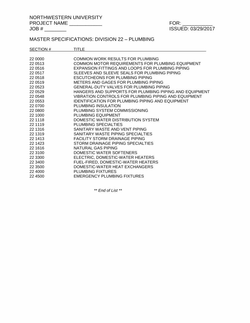
NORTHWESTERN UNIVERSITY PROJECT NAME ____________ FOR: ___________ JOB # ________ ISSUED: 03/29/2017
MASTER SPECIFICATIONS: DIVISION 22 – PLUMBING
SECTION # TITLE
22 0000 COMMON WORK RESULTS FOR PLUMBING 22 0513 COMMON MOTOR REQUIREMENTS FOR PLUMBING EQUIPMENT 22 0516 EXPANSION FITTINGS AND LOOPS FOR PLUMBING PIPING 22 0517 SLEEVES AND SLEEVE SEALS FOR PLUMBING PIPING 22 0518 ESCUTCHEONS FOR PLUMBING PIPING 22 0519 METERS AND GAGES FOR PLUMBING PIPING 22 0523 GENERAL-DUTY VALVES FOR PLUMBING PIPING 22 0529 HANGERS AND SUPPORTS FOR PLUMBING PIPING AND EQUIPMENT 22 0548 VIBRATION CONTROLS FOR PLUMBING PIPING AND EQUIPMENT 22 0553 IDENTIFICATION FOR PLUMBING PIPING AND EQUIPMENT 22 0700 PLUMBING INSULATION 22 0800 PLUMBING SYSTEM COMMISSIONING 22 1000 PLUMBING EQUIPMENT 22 1118 DOMESTIC WATER DISTRIBUTION SYSTEM 22 1119 PLUMBING SPECIALTIES 22 1316 SANITARY WASTE AND VENT PIPING 22 1319 SANITARY WASTE PIPING SPECIALTIES 22 1413 FACILITY STORM DRAINAGE PIPING 22 1423 STORM DRAINAGE PIPING SPECIALTIES 22 1616 NATURAL GAS PIPING 22 3100 DOMESTIC WATER SOFTENERS 22 3300 ELECTRIC, DOMESTIC-WATER HEATERS 22 3400 FUEL-FIRED, DOMESTIC-WATER HEATERS 22 3500 DOMESTIC-WATER HEAT EXCHANGERS 22 4000 PLUMBING FIXTURES 22 4500 EMERGENCY PLUMBING FIXTURES
** End of List **
NORTHWESTERN UNIVERSITY PROJECT NAME ____________ FOR: ___________ JOB # ________ ISSUED: 03/29/2017
COMMON WORK RESULTS FOR PLUMBING 22 0000 - 1
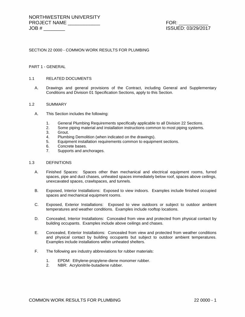
SECTION 22 0000 - COMMON WORK RESULTS FOR PLUMBING
PART 1 - GENERAL
1.1 RELATED DOCUMENTS
A. Drawings and general provisions of the Contract, including General and Supplementary Conditions and Division 01 Specification Sections, apply to this Section.
1.2 SUMMARY
A. This Section includes the following:
1. General Plumbing Requirements specifically applicable to all Division 22 Sections. 2. Some piping material and installation instructions common to most piping systems. 3. Grout. 4. Plumbing Demolition (when indicated on the drawings). 5. Equipment installation requirements common to equipment sections. 6. Concrete bases. 7. Supports and anchorages.
1.3 DEFINITIONS
A. Finished Spaces: Spaces other than mechanical and electrical equipment rooms, furred spaces, pipe and duct chases, unheated spaces immediately below roof, spaces above ceilings, unexcavated spaces, crawlspaces, and tunnels.
B. Exposed, Interior Installations: Exposed to view indoors. Examples include finished occupied spaces and mechanical equipment rooms.
C. Exposed, Exterior Installations: Exposed to view outdoors or subject to outdoor ambient temperatures and weather conditions. Examples include rooftop locations.
D. Concealed, Interior Installations: Concealed from view and protected from physical contact by building occupants. Examples include above ceilings and chases.
E. Concealed, Exterior Installations: Concealed from view and protected from weather conditions and physical contact by building occupants but subject to outdoor ambient temperatures. Examples include installations within unheated shelters.
F. The following are industry abbreviations for rubber materials:
1. EPDM: Ethylene-propylene-diene monomer rubber. 2. NBR: Acrylonitrile-butadiene rubber.
NORTHWESTERN UNIVERSITY PROJECT NAME ____________ FOR: ___________ JOB # ________ ISSUED: 03/29/2017
COMMON WORK RESULTS FOR PLUMBING 22 0000 - 2
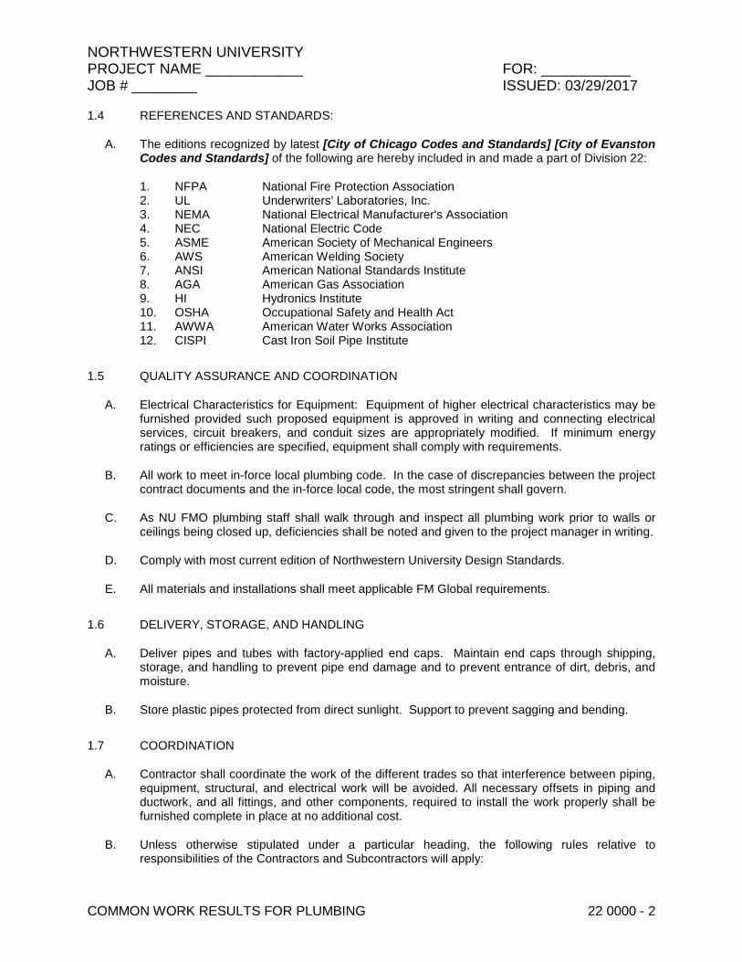
1.4 REFERENCES AND STANDARDS:
A. The editions recognized by latest [City of Chicago Codes and Standards] [City of Evanston Codes and Standards] of the following are hereby included in and made a part of Division 22:
1. NFPA National Fire Protection Association 2. UL Underwriters' Laboratories, Inc. 3. NEMA National Electrical Manufacturer's Association 4. NEC National Electric Code 5. ASME American Society of Mechanical Engineers 6. AWS American Welding Society 7. ANSI American National Standards Institute 8. AGA American Gas Association 9. HI Hydronics Institute 10. OSHA Occupational Safety and Health Act 11. AWWA American Water Works Association 12. CISPI Cast Iron Soil Pipe Institute
1.5 QUALITY ASSURANCE AND COORDINATION
A. Electrical Characteristics for Equipment: Equipment of higher electrical characteristics may be furnished provided such proposed equipment is approved in writing and connecting electrical services, circuit breakers, and conduit sizes are appropriately modified. If minimum energy ratings or efficiencies are specified, equipment shall comply with requirements.
B. All work to meet in-force local plumbing code. In the case of discrepancies between the project contract documents and the in-force local code, the most stringent shall govern.
C. As NU FMO plumbing staff shall walk through and inspect all plumbing work prior to walls or ceilings being closed up, deficiencies shall be noted and given to the project manager in writing.
D. Comply with most current edition of Northwestern University Design Standards.
E. All materials and installations shall meet applicable FM Global requirements.
1.6 DELIVERY, STORAGE, AND HANDLING
A. Deliver pipes and tubes with factory-applied end caps. Maintain end caps through shipping, storage, and handling to prevent pipe end damage and to prevent entrance of dirt, debris, and moisture.
B. Store plastic pipes protected from direct sunlight. Support to prevent sagging and bending.
1.7 COORDINATION
A. Contractor shall coordinate the work of the different trades so that interference between piping, equipment, structural, and electrical work will be avoided. All necessary offsets in piping and ductwork, and all fittings, and other components, required to install the work properly shall be furnished complete in place at no additional cost.
B. Unless otherwise stipulated under a particular heading, the following rules relative to responsibilities of the Contractors and Subcontractors will apply:
NORTHWESTERN UNIVERSITY PROJECT NAME ____________ FOR: ___________ JOB # ________ ISSUED: 03/29/2017
COMMON WORK RESULTS FOR PLUMBING 22 0000 - 3
1. Make-up water piping connections shall be provided by the Plumbing Contractor to within five (5) feet of the required point of connection to the equipment and there terminated with a shut-off valve. Each trade shall make the final connection to the equipment it installs.
2. Ceiling access panels will be installed by the General Contractor at locations determined by the Plumbing Contractor.
3. The Plumbing Contractor or subcontractor shall install all roughing-in pertaining to his trade for each item of equipment furnished under another Section of the Specifications or by the Owner.
4. The Plumbing Contractor shall make final connections of equipment to rough-ins.
1.8 EQUIPMENT START-UP
A. Start-up of all plumbing equipment shall be video-recorded by the plumbing contractor. Two DVD copies shall be turned over to the Owner’s maintenance staff.
1.9 TESTING AND REPAIR
A. All piping and ductwork systems shall be thoroughly cleaned and flushed prior to final testing.
B. Pressure testing shall be completed for the following piping systems:
1. Domestic water, sanitary and vent, storm and gas piping systems, and other systems as noted on the plans.
C. All testing must be witnessed and accurately recorded noting methods of testing, times, dates, and results.
D. Any damage as a result of tests shall be repaired or damaged materials replaced at no cost to the Owner.
1.10 FINAL COMPLETION
A. All work shall be cleaned prior to issuance of Substantial Completion.
B. Retouch or repaint factory painted prime and finish coats where scratched or damaged.
C. Deliver any equipment as required by this Specification to Owner and obtained signed receipts of delivery.
D. Clean equipment, restore damaged materials, and leave the Work in acceptable condition.
E. Remove all site tools, equipment, surplus materials and rubbish continuously at no additional cost to the Owner.
F. Contractor shall submit written certificates warranting each item of equipment.
NORTHWESTERN UNIVERSITY PROJECT NAME ____________ FOR: ___________ JOB # ________ ISSUED: 03/29/2017
COMMON WORK RESULTS FOR PLUMBING 22 0000 - 4
PART 2 - PRODUCTS
2.1 EQUIPMENT AND MATERIALS:
A. All equipment and materials shall be furnished in strict accordance with the equipment named and according to Specification requirements. Each bid shall be based upon one of the materials or manufacturers specified.
B. Equipment and materials specified shall be considered to have prior approval, but submittal for approval is required. Furnish construction drawings to other Contractors when required to coordinate construction.
C. Where multiple manufacturers are named the drawings and specifications are based on the requirements and layouts for the equipment of the first named manufacturer. Any change required by the use of other named manufacturers such as revisions to foundations, bases, piping, controls, wiring, openings, and appurtenances shall be made by the Contractor at no additional cost to the Owner.
2.2 PIPE, TUBE, AND FITTINGS - GENERAL
A. Refer to individual Division 22 Piping Sections for pipe, tube, and fitting materials and joining methods.
B. Pipe Threads: ASME B1.20.1 for factory-threaded pipe and pipe fittings.
2.3 GROUT
A. Description: ASTM C 1107, Grade B, non-shrink and nonmetallic, dry hydraulic-cement grout.
1. Characteristics: Post-hardening, volume-adjusting, non-staining, noncorrosive, nongaseous, and recommended for interior and exterior applications.
2. Design Mix: 5000-psi, 28-day compressive strength. 3. Packaging: Premixed and factory packaged.
PART 3 - EXECUTION
3.1 PLUMBING DEMOLITION (When indicated on the drawings)
A. Refer to applicable Division 01 Section covering cutting and patching and applicable Division 02 Section covering selective structure demolition for general demolition requirements and procedures.
B. If pipe, insulation, or equipment to remain is damaged in appearance or is unserviceable, remove damaged or unserviceable portions and replace with new products of equal capacity and quality.
C. All unused waste, water and vent that is no longer in service shall be removed from ceilings, walls and floors. No dead piping will be allowed to stay. Underground piping shall also be removed. If piping cannot be removed underground it shall be capped at the main and the pipe shall be pumped and filled with a flowable fill.
NORTHWESTERN UNIVERSITY PROJECT NAME ____________ FOR: ___________ JOB # ________ ISSUED: 03/29/2017
COMMON WORK RESULTS FOR PLUMBING 22 0000 - 5
D. A MOP will be required when filling abandoned sewers, old water mains or any plumbing piping that is buried in the ground.
E. Before abandoning any plumbing piping underground, the piping shall be inspected, video recorded, mapped on an as built and FMDC and FMO shall approve abandoning the piping.
F. After completion of of all work, all of the sewer systems involved with the project in their entirety, shall be thoroughly cleaned out to remove all grit, or other foreign matter. This shall include the use of a camera and recording to a flash drive or DVD and a copy of the recording included with the close out documents.
3.2 PIPING SYSTEMS - COMMON REQUIREMENTS
A. All materials and/or equipment shall be installed per manufacturer's recommendations and instructions.
B. When temporary water is required, an approved backflow device shall be used and testing reports from device shall be sent to FMO plumbing foreman for verification.
C. Install piping according to the following requirements and Division 22 Sections specifying piping systems.
D. Drawing plans, schematics, and diagrams indicate general location and arrangement of piping systems. Indicated locations and arrangements were used to size pipe and calculate friction loss, expansion, pump sizing, and other design considerations. Install piping as indicated unless deviations to layout are approved on Coordination Drawings.
E. Install piping in concealed locations, unless otherwise indicated and except in equipment rooms and service areas.
F. Install piping indicated to be exposed and piping in equipment rooms and service areas at right angles or parallel to building walls. Diagonal runs are prohibited unless specifically indicated otherwise.
G. Piping shall not project beyond walls or steel lines nor shall it hang below slabs more than is absolutely necessary. Particular attention shall be paid to the required clearances.
H. Offset piping where required to avoid interference with other work, to provide greater headroom or clearance, or to conceal pipe more readily. Offsets shall be properly drained or trapped where necessary.
I. Provide swing joints and expansion bends wherever required to allow the piping to expand without undue stress to connections or equipment.
J. Exposed piping around fixtures or in other conspicuous places shall not show tool marks at fittings.
K. Isolate pipe from the building construction to prevent transmission of vibration to the structure and to eliminate noise.
L. Install piping such that any equipment connected to piping may be removed by disconnecting two (2) flanges or unions and removing only one or two pipe sections. All equipment shall have bolted or screwed flanges or unions at pipe connections.
NORTHWESTERN UNIVERSITY PROJECT NAME ____________ FOR: ___________ JOB # ________ ISSUED: 03/29/2017
COMMON WORK RESULTS FOR PLUMBING 22 0000 - 6
M. Install fittings for changes in direction and branch connections. T-drill system for mechanically formed tee connections and couplings, and Victaulic hole cut piping system are not allowed.
N. Do not route piping through transformer vaults or above transformers, panelboards, or switchboards, including the required service space for this equipment, unless the piping is serving this equipment.
O. Install groups of pipes parallel to each other, spaced to permit applying insulation and servicing of valves.
P. Install piping above accessible ceilings to allow sufficient space for ceiling panel removal.
Q. Install piping to permit valve servicing.
R. Install piping at indicated slopes.
S. Install piping free of sags and bends.
T. Install piping to allow application of insulation.
U. Eccentric reducing couplings shall be provided in all cases where air or water pockets would otherwise occur due to a reduction in pipe size.
V. Cap and plug all openings in pipes during construction with suitable metal plugs or cap to keep out dirt and rubbish until equipment is connected.
W. Install drains, consisting of a tee fitting, NPS 3/4 full port-ball valve, and short NPS 3/4 threaded nipple with cap, at low points in piping system mains and elsewhere as required for system drainage.
X. Select system components with pressure rating equal to or greater than system operating pressure.
Y. Fire-Barrier Penetrations: Maintain indicated fire rating of walls, partitions, ceilings, and floors at pipe penetrations. Seal pipe penetrations with firestop materials. Refer to Division 07 Section "Penetration Firestopping" for materials.
Z. Verify final equipment locations for roughing-in.
AA. Refer to equipment specifications in other Sections of these Specifications for roughing-in requirements.
BB. Provide proper access to materials and equipment that require inspection, repair, service, or maintenance.
CC. Minimum service access size for materials equipment/components above ceilings shall be 24" square.
3.3 PIPING JOINT CONSTRUCTION
A. Join pipe and fittings according to the following requirements and Division 22 Sections specifying piping systems.

NORTHWESTERN UNIVERSITY PROJECT NAME ____________ FOR: ___________ JOB # ________ ISSUED: 03/29/2017
COMMON WORK RESULTS FOR PLUMBING 22 0000 - 7
B. Ream ends of pipes and tubes and remove burrs. Bevel plain ends of steel pipe.
C. Remove scale, slag, dirt, and debris from inside and outside of pipe and fittings before assembly.
D. Threaded Joints: Thread pipe with tapered pipe threads according to ASME B1.20.1. Cut threads full and clean using sharp dies. Ream threaded pipe ends to remove burrs and restore full ID. Join pipe fittings and valves as follows:
1. Apply appropriate tape or thread compound to external pipe threads unless dry seal threading is specified.
2. Damaged Threads: Do not use pipe or pipe fittings with threads that are corroded or damaged. Do not use pipe sections that have cracked or open welds.
3.4 PIPING CONNECTIONS
A. Pipe sizes indicated shall be carried full size to equipment served. Any change of size to match equipment connection shall be made within one foot of the equipment. At temperature control valves with sizes smaller than connected lines, reduction shall be made immediately adjacent to valves.
3.5 EQUIPMENT INSTALLATION - COMMON REQUIREMENTS
A. Install equipment to allow maximum possible headroom unless specific mounting heights are not indicated.
B. Install equipment level and plumb, parallel and perpendicular to other building systems and components in exposed interior spaces, unless otherwise indicated.
C. Install Plumbing equipment to facilitate service, maintenance, and repair or replacement of components. Connect equipment for ease of disconnecting, with minimum interference to other installations. Extend grease fittings to accessible locations.
D. Install equipment to allow right of way for piping installed at required slope.
3.6 CONCRETE BASES
A. Concrete Bases: Anchor equipment to concrete base according to equipment manufacturer's written instructions and according to seismic codes at Project.
1. Construct concrete bases of dimensions indicated, but not less than 4 inches larger in both directions than supported unit. Install dowel rods to connect concrete base to concrete floor.
2. Unless otherwise indicated, install dowel rods on 18-inch centers around the full perimeter of the base.
3. Install epoxy-coated anchor bolts for supported equipment that extend through concrete base, and anchor into structural concrete floor.
4. Place and secure anchorage devices. Use supported equipment manufacturer's setting drawings, templates, diagrams, instructions, and directions furnished with items to be embedded.
5. Install anchor bolts to elevations required for proper attachment to supported equipment. 6. Install anchor bolts according to anchor-bolt manufacturer's written instructions.
NORTHWESTERN UNIVERSITY PROJECT NAME ____________ FOR: ___________ JOB # ________ ISSUED: 03/29/2017
COMMON WORK RESULTS FOR PLUMBING 22 0000 - 8
7. Use 3000-psi, 28-day compressive-strength concrete and reinforcement as specified in Division 03 Section “Cast-in-Place Concrete”
3.7 ERECTION OF METAL SUPPORTS AND ANCHORAGES
A. Refer to Division 05 Section "Metal Fabrications" for structural steel.
B. Cut, fit, and place miscellaneous metal supports accurately in location, alignment, and elevation to support and anchor Plumbing materials and equipment.
C. Field Welding: Comply with AWS D1.1.
3.8 GROUTING
A. Mix and install grout for Plumbing equipment base bearing surfaces, pump and other equipment base plates, and anchors.
B. Clean surfaces that will come into contact with grout.
C. Provide forms as required for placement of grout.
D. Avoid air entrapment during placement of grout.
E. Place grout, completely filling equipment bases.
F. Place grout on concrete bases and provide smooth bearing surface for equipment.
G. Place grout around anchors.
H. Cure placed grout.
END OF SECTION 22 0000

NORTHWESTERN UNIVERSITY PROJECT NAME ____________ FOR: ___________ JOB # ________ ISSUED: 03/29/2017
COMMON MOTOR REQUIREMENTS FOR PLUMBING 22 0513 - 1
SECTION 22 0513 - COMMON MOTOR REQUIREMENTS FOR PLUMBING EQUIPMENT
PART 1 - GENERAL
1.1 RELATED DOCUMENTS
A. Drawings and general provisions of the Contract, including General and Supplementary Conditions and Division 01 Specification Sections, apply to this Section.
1.2 SUMMARY
A. Section includes general requirements for single-phase and polyphase, general-purpose, horizontal, small and medium, squirrel-cage induction motors for use on ac power systems up to 600 V and installed at equipment manufacturer's factory or shipped separately by equipment manufacturer for field installation.
1.3 COORDINATION
A. Coordinate features of motors, installed units, and accessory devices to be compatible with the following:
1. Motor controllers. 2. Torque, speed, and horsepower requirements of the load. 3. Ratings and characteristics of supply circuit and required control sequence. 4. Ambient and environmental conditions of installation location.
PART 2 - PRODUCTS
2.1 GENERAL MOTOR REQUIREMENTS
A. Comply with requirements in this Section except when stricter requirements are specified in plumbing equipment schedules or Sections.
B. Comply with NEMA MG 1 unless otherwise indicated.
C. Comply with IEEE 841 for severe-duty motors.
2.2 MOTOR CHARACTERISTICS
A. Duty: Continuous duty at ambient temperature of 40 deg C and at altitude of 3300 feet above sea level.
B. Capacity and Torque Characteristics: Sufficient to start, accelerate, and operate connected loads at designated speeds, at installed altitude and environment, with indicated operating sequence, and without exceeding nameplate ratings or considering service factor.
NORTHWESTERN UNIVERSITY PROJECT NAME ____________ FOR: ___________ JOB # ________ ISSUED: 03/29/2017
COMMON MOTOR REQUIREMENTS FOR PLUMBING 22 0513 - 2
2.3 POLYPHASE MOTORS
A. Description: NEMA MG 1, Design B, medium induction motor.
B. Efficiency: Energy efficient, as defined in NEMA MG 1.
C. Service Factor: 1.15.
D. Multispeed Motors: Variable torque.
1. For motors with 2:1 speed ratio, consequent pole, single winding. 2. For motors with other than 2:1 speed ratio, separate winding for each speed.
E. Rotor: Random-wound, squirrel cage.
F. Bearings: Regreasable, shielded, antifriction ball bearings suitable for radial and thrust loading.
G. Temperature Rise: Match insulation rating.
H. Insulation: Class F.
I. Code Letter Designation:
1. Motors 15 HP and Larger: NEMA starting Code F or Code G. 2. Motors Smaller than 15 HP: Manufacturer's standard starting characteristic.
J. Enclosure Material: Cast iron for motor frame sizes 324T and larger; rolled steel for motor frame sizes smaller than 324T.
2.4 POLYPHASE MOTORS WITH ADDITIONAL REQUIREMENTS
A. Motors Used with Reduced-Voltage and Multispeed Controllers: Match wiring connection requirements for controller with required motor leads. Provide terminals in motor terminal box, suited to control method.
B. Motors Used with Variable Frequency Controllers: Ratings, characteristics, and features coordinated with and approved by controller manufacturer.
1. Windings: Copper magnet wire with moisture-resistant insulation varnish, designed and tested to resist transient spikes, high frequencies, and short time rise pulses produced by pulse-width modulated inverters.
2. Energy- and Premium-Efficient Motors: Class B temperature rise; Class F insulation. 3. Inverter-Duty Motors: Class F temperature rise; Class H insulation. 4. Thermal Protection: Comply with NEMA MG 1 requirements for thermally protected
motors.
2.5 SINGLE-PHASE MOTORS
A. Motors larger than 1/20 hp shall be one of the following, to suit starting torque and requirements of specific motor application:
1. Permanent-split capacitor.

NORTHWESTERN UNIVERSITY PROJECT NAME ____________ FOR: ___________ JOB # ________ ISSUED: 03/29/2017
COMMON MOTOR REQUIREMENTS FOR PLUMBING 22 0513 - 3
2. Split phase. 3. Capacitor start, inductor run. 4. Capacitor start, capacitor run.
B. Multispeed Motors: Variable-torque, permanent-split-capacitor type.
C. Bearings: Prelubricated, antifriction ball bearings or sleeve bearings suitable for radial and thrust loading.
D. Motors 1/20 HP and Smaller: Shaded-pole type.
E. Thermal Protection: Internal protection to automatically open power supply circuit to motor when winding temperature exceeds a safe value calibrated to temperature rating of motor insulation. Thermal-protection device shall automatically reset when motor temperature returns to normal range.
PART 3 - EXECUTION (Not Applicable)
END OF SECTION 22 0513

NORTHWESTERN UNIVERSITY PROJECT NAME ____________ FOR: ___________ JOB # ________ ISSUED: 03/29/2017
COMMON MOTOR REQUIREMENTS FOR PLUMBING 22 0513 - 4
THIS PAGE IS INTENTIONALLY BLANK

NORTHWESTERN UNIVERSITY PROJECT NAME ____________ FOR: ___________ JOB # ________ ISSUED: 03/29/2017
EXPANSION FITTINGS AND LOOPS FOR PLUMBING PIPING 22 0516 - 1
SECTION 22 0516 - EXPANSION FITTINGS AND LOOPS FOR PLUMBING PIPING
PART 1 - GENERAL
1.1 RELATED DOCUMENTS
A. Drawings and general provisions of the Contract, including General and Supplementary Conditions and Division 01 Specification Sections, apply to this Section.
1.2 SUMMARY
A. Section Includes:
1. Flexible-hose packless expansion joints. 2. Grooved-joint expansion joints. 3. Alignment guides and anchors. 4. Pipe loop installation.
1.3 PERFORMANCE REQUIREMENTS
A. Compatibility: Products shall be suitable for piping service fluids, materials, working pressures, and temperatures.
B. Capability: Products to absorb 200 percent of maximum axial movement between anchors.
1.4 ACTION SUBMITTALS
A. Product Data: For each type of product indicated.
B. Delegated-Design Submittal: For each anchor and alignment guide indicated to comply with performance requirements and design criteria, including analysis data signed and sealed by the qualified professional engineer responsible for their preparation.
1. Design Calculations: Calculate requirements for thermal expansion of piping systems and for selecting and designing expansion joints, loops, and swing connections.
2. Anchor Details: Detail fabrication of each anchor indicated. Show dimensions and methods of assembly and attachment to building structure.
3. Alignment Guide Details: Detail field assembly and attachment to building structure. 4. Schedule: Indicate type, manufacturer's number, size, material, pressure rating, end
connections, and location for each expansion joint.
1.5 INFORMATIONAL SUBMITTALS
A. Welding certificates.
B. Product Certificates: For each type of expansion joint, from manufacturer.

NORTHWESTERN UNIVERSITY PROJECT NAME ____________ FOR: ___________ JOB # ________ ISSUED: 03/29/2017
EXPANSION FITTINGS AND LOOPS FOR PLUMBING PIPING 22 0516 - 2
1.6 CLOSEOUT SUBMITTALS
A. Maintenance Data: For expansion joints to include in maintenance manuals.
1.7 QUALITY ASSURANCE
A. Welding Qualifications: Qualify procedures and personnel according to the following:
1. AWS D1.1/D1.1M, "Structural Welding Code - Steel." 2. ASME Boiler and Pressure Vessel Code: Section IX.
PART 2 - PRODUCTS
2.1 PACKLESS EXPANSION JOINTS
A. Flexible-Hose Packless Expansion Joints:
1. Manufacturers: Subject to compliance with requirements, provide products by one of the following:
a. Flex-Hose Co., Inc. b. Flexicraft Industries. c. Metraflex, Inc.
2. Description: Manufactured assembly with inlet and outlet elbow fittings and two flexible-metal-hose legs joined by long-radius, 180-degree return bend or center section of flexible hose.
3. Flexible Hose: Corrugated-metal inner hoses and braided outer sheaths. 4. Expansion Joints for Copper Tubing NPS 2 (DN 50) and Smaller: Copper-alloy fittings
with solder-joint end connections.
a. Bronze hoses and single-braid bronze sheaths with 450 psig at 70 deg F (3100 kPa at 21 deg C) and 340 psig at 450 deg F (2340 kPa at 232 deg C) ratings.
5. Expansion Joints for Copper Tubing NPS 2-1/2 to NPS 4 (DN 65 to DN 100): Copper-alloy fittings with threaded end connections.
a. Stainless-steel hoses and single-braid, stainless-steel sheaths with 300 psig at 70 deg F (2070 kPa at 21 deg C) and 225 psig at 450 deg F (1550 kPa at 232 deg C) ratings.
6. Expansion Joints for Steel Piping NPS 2 (DN 50) and Smaller: Stainless-steel fittings with threaded end connections.
a. Stainless-steel hoses and single-braid, stainless-steel sheaths with 450 psig at 70 deg F (3100 kPa at 21 deg C) and 325 psig at 600 deg F (2250 kPa at 315 deg C) ratings.
7. Expansion Joints for Steel Piping NPS 2-1/2 to NPS 6 (DN 65 to DN 150): Stainless-steel fittings with flanged end connections.

NORTHWESTERN UNIVERSITY PROJECT NAME ____________ FOR: ___________ JOB # ________ ISSUED: 03/29/2017
EXPANSION FITTINGS AND LOOPS FOR PLUMBING PIPING 22 0516 - 3
a. Stainless-steel hoses and single-braid, stainless-steel sheaths with 200 psig at 70 deg F (1380 kPa at 21 deg C) and 145 psig at 600 deg F (1000 kPa at 315 deg C) ratings.
8. Expansion Joints for Steel Piping NPS 8 to NPS 12 (DN 200 to DN 300): Stainless-steel fittings with flanged end connections.
a. Stainless-steel hoses and single-braid, stainless-steel sheaths with 125 psig at 70 deg F (860 kPa at 21 deg C) and 90 psig at 600 deg F (625 kPa at 315 deg C) ratings.
2.2 GROOVED-JOINT EXPANSION JOINTS
A. Manufacturers: Subject to compliance with requirements, provide products by one of the following:
1. Victaulic Company.
B. Description: Factory-assembled expansion joint made of several grooved-end pipe nipples, couplings, and grooved joints.
C. Standard: AWWA C606, for grooved joints.
D. Nipples: Galvanized, ASTM A 53/A 53M, Schedule 40, Type E or S, steel pipe with grooved ends.
E. Couplings: Five, seven, ten, or twelve, flexible type for steel-pipe dimensions. Include ferrous housing sections, Buna-N or EPDM gaskets suitable for project duties, and bolts and nuts.
2.3 ALIGNMENT GUIDES AND ANCHORS
A. Alignment Guides:
1. Manufacturers: Subject to compliance with requirements, provide products by one of the following:
a. Adsco Manufacturing LLC. b. Advanced Thermal Systems, Inc. c. Flex-Hose Co., Inc. d. Flexicraft Industries. e. Hyspan Precision Products, Inc. f. Metraflex, Inc. g. Unisource Manufacturing, Inc. h. U.S. Bellows, Inc.
2. Description: Steel, factory-fabricated alignment guide, with bolted two-section outer cylinder and base for attaching to structure; with two-section guiding spider for bolting to pipe.
B. Anchor Materials:
1. Steel Shapes and Plates: ASTM A 36/A 36M. 2. Bolts and Nuts: ASME B18.10 or ASTM A 183, steel hex head.
NORTHWESTERN UNIVERSITY PROJECT NAME ____________ FOR: ___________ JOB # ________ ISSUED: 03/29/2017
EXPANSION FITTINGS AND LOOPS FOR PLUMBING PIPING 22 0516 - 4
3. Washers: ASTM F 844, steel, plain, flat washers. 4. Mechanical Fasteners: Insert-wedge-type stud with expansion plug anchor for use in
hardened portland cement concrete, with tension and shear capacities appropriate for application.
a. Stud: Threaded, zinc-coated carbon steel. b. Expansion Plug: Zinc-coated steel. c. Washer and Nut: Zinc-coated steel.
5. Chemical Fasteners: Insert-type-stud, bonding-system anchor for use with hardened portland cement concrete, with tension and shear capacities appropriate for application.
a. Bonding Material: ASTM C 881/C 881M, Type IV, Grade 3, two-component epoxy resin suitable for surface temperature of hardened concrete where fastener is to be installed.
b. Stud: ASTM A 307, zinc-coated carbon steel with continuous thread on stud unless otherwise indicated.
c. Washer and Nut: Zinc-coated steel.
PART 3 - EXECUTION
3.1 EXPANSION-JOINT INSTALLATION
A. Install expansion joints of sizes matching sizes of piping in which they are installed.
B. Install grooved-joint expansion joints to grooved-end steel piping
3.2 PIPE LOOP INSTALLATION
A. Connect risers and branch connections to mains with at least five pipe fittings including tee in main.
B. Connect risers and branch connections to terminal units with at least four pipe fittings including tee in riser.
C. Connect mains and branch connections to terminal units with at least four pipe fittings including tee in main.
3.3 ALIGNMENT-GUIDE AND ANCHOR INSTALLATION
A. Install alignment guides to guide expansion and to avoid end-loading and torsional stress.
B. Install two guide(s) on each side of pipe expansion fittings and loops. Install guides nearest to expansion joint not more than four pipe diameters from expansion joint.
C. Attach guides to pipe and secure guides to building structure.
D. Install anchors at locations to prevent stresses from exceeding those permitted by ASME B31.9 and to prevent transfer of loading and stresses to connected equipment.

NORTHWESTERN UNIVERSITY PROJECT NAME ____________ FOR: ___________ JOB # ________ ISSUED: 03/29/2017
EXPANSION FITTINGS AND LOOPS FOR PLUMBING PIPING 22 0516 - 5
E. Anchor Attachments:
1. Anchor Attachment to Black-Steel Pipe: Attach by welding. Comply with ASME B31.9 and ASME Boiler and Pressure Vessel Code: Section IX, "Welding and Brazing Qualifications."
2. Anchor Attachment to Galvanized-Steel Pipe: Attach with pipe hangers. Use MSS SP-69, Type 42, riser clamp welded to anchor.
3. Anchor Attachment to Copper Tubing: Attach with pipe hangers. Use MSS SP-69, Type 24, U-bolts bolted to anchor.
F. Fabricate and install steel anchors by welding steel shapes, plates, and bars. Comply with ASME B31.9 and AWS D1.1/D1.1M.
1. Anchor Attachment to Steel Structural Members: Attach by welding. 2. Anchor Attachment to Concrete Structural Members: Attach by fasteners. Follow
fastener manufacturer's written instructions.
G. Use grout to form flat bearing surfaces for guides and anchors attached to concrete.
END OF SECTION 22 0516

NORTHWESTERN UNIVERSITY PROJECT NAME ____________ FOR: ___________ JOB # ________ ISSUED: 03/29/2017
EXPANSION FITTINGS AND LOOPS FOR PLUMBING PIPING 22 0516 - 6
THIS PAGE IS INTENTIONALLY BLANK
NORTHWESTERN UNIVERSITY PROJECT NAME ____________ FOR: ___________ JOB # ________ ISSUED: 03/29/2017
SLEEVES AND SLEEVE SEALS FOR PLUMBING PIPING 22 0517 - 1
SECTION 22 0517 - SLEEVES AND SLEEVE SEALS FOR PLUMBING PIPING
PART 1 - GENERAL
1.1 RELATED DOCUMENTS
A. Drawings and general provisions of the Contract, including General and Supplementary Conditions and Division 01 Specification Sections, apply to this Section.
1.2 SUMMARY
A. Section Includes:
1. Sleeves. 2. Stack-sleeve fittings. 3. Sleeve-seal systems. 4. Sleeve-seal fittings. 5. Grout.
1.3 ACTION SUBMITTALS
A. Product Data: For each type of product indicated.
PART 2 - PRODUCTS
2.1 SLEEVES
A. Cast-Iron Wall Pipes: Cast or fabricated of cast or ductile iron and equivalent to ductile-iron pressure pipe, with plain ends and integral waterstop unless otherwise indicated.
B. Galvanized-Steel Wall Pipes: ASTM A 53/A 53M, Schedule 40, with plain ends and welded steel collar; zinc coated.
C. Galvanized-Steel-Pipe Sleeves: ASTM A 53/A 53M, Type E, Grade B, Schedule 40, zinc coated, with plain ends.
D. Galvanized-Steel-Sheet Sleeves: 0.0239-inch (0.6-mm) minimum thickness; round tube closed with welded longitudinal joint.
E. Molded-PE or -PP Sleeves: Removable, tapered-cup shaped, and smooth outer surface with nailing flange for attaching to wooden forms.

NORTHWESTERN UNIVERSITY PROJECT NAME ____________ FOR: ___________ JOB # ________ ISSUED: 03/29/2017
SLEEVES AND SLEEVE SEALS FOR PLUMBING PIPING 22 0517 - 2
2.2 STACK-SLEEVE FITTINGS
A. Manufacturers: Subject to compliance with requirements, provide products by one of the following:
1. Smith, Jay R. Mfg. Co. 2. Zurn Specification Drainage Operation; Zurn Plumbing Products Group.
B. Description: Manufactured, cast-iron sleeve with integral clamping flange. Include clamping ring, bolts, and nuts for membrane flashing.
1. Underdeck Clamp: Clamping ring with setscrews.
2.3 SLEEVE-SEAL SYSTEMS
A. Manufacturers: Subject to compliance with requirements, provide products by one of the following:
1. Advance Products & Systems, Inc. 2. CALPICO, Inc. 3. Metraflex Company (The). 4. Pipeline Seal and Insulator, Inc. 5. Proco Products, Inc.
B. Description: Modular sealing-element unit, designed for field assembly, for filling annular space between piping and sleeve.
1. Sealing Elements: EPDM-rubber or NBR interlocking links shaped to fit surface of pipe. Include type and number required for pipe material and size of pipe.
2. Pressure Plates: Carbon steel or stainless steel. 3. Connecting Bolts and Nuts: Carbon steel, with corrosion-resistant coating, or stainless
steel of length required to secure pressure plates to sealing elements.
2.4 SLEEVE-SEAL FITTINGS
A. Manufacturers: Subject to compliance with requirements, provide products by one of the following:
1. Presealed Systems.
B. Description: Manufactured plastic, sleeve-type, waterstop assembly made for imbedding in concrete slab or wall. Unit has plastic or rubber waterstop collar with center opening to match piping OD.
2.5 GROUT
A. Standard: ASTM C 1107/C 1107M, Grade B, post-hardening and volume-adjusting, dry, hydraulic-cement grout.
B. Characteristics: Nonshrink; recommended for interior and exterior applications.
C. Design Mix: 5000-psi (34.5-MPa), 28-day compressive strength.

NORTHWESTERN UNIVERSITY PROJECT NAME ____________ FOR: ___________ JOB # ________ ISSUED: 03/29/2017
SLEEVES AND SLEEVE SEALS FOR PLUMBING PIPING 22 0517 - 3
D. Packaging: Premixed and factory packaged.
PART 3 - EXECUTION
3.1 SLEEVE INSTALLATION
A. Install sleeves for piping passing through penetrations in floors, partitions, roofs, and walls.
B. For sleeves that will have sleeve-seal system installed, select sleeves of size large enough to provide 1-inch (25-mm) annular clear space between piping and concrete slabs and walls.
C. Install sleeves in concrete floors, concrete roof slabs, and concrete walls as new slabs and walls are constructed.
1. Cut sleeves to length for mounting flush with both surfaces.
a. Exception: Extend sleeves installed in floors of mechanical equipment areas or other wet areas 2 inches (50 mm) above finished floor level.
2. Using grout, seal the space outside of sleeves in slabs and walls without sleeve-seal system.
D. Install sleeves for pipes passing through interior partitions.
1. Cut sleeves to length for mounting flush with both surfaces. 2. Install sleeves that are large enough to provide 1/4-inch (6.4-mm) annular clear space
between sleeve and pipe or pipe insulation. 3. Seal annular space between sleeve and piping or piping insulation; use joint sealants
appropriate for size, depth, and location of joint. Comply with requirements for sealants specified in Section 079200 "Joint Sealants."
E. Fire-Barrier Penetrations: Maintain indicated fire rating of walls, partitions, ceilings, and floors at pipe penetrations. Seal pipe penetrations with firestop materials. Comply with requirements for firestopping specified in Section 078413 "Penetration Firestopping."
3.2 STACK-SLEEVE-FITTING INSTALLATION
A. Install stack-sleeve fittings in new slabs as slabs are constructed.
1. Install fittings that are large enough to provide 1/4-inch (6.4-mm) annular clear space between sleeve and pipe or pipe insulation.
2. Secure flashing between clamping flanges for pipes penetrating floors with membrane waterproofing. Comply with requirements for flashing specified in Section 076200 "Sheet Metal Flashing and Trim."
3. Install section of cast-iron soil pipe to extend sleeve to 2 inches (50 mm) above finished floor level.
4. Extend cast-iron sleeve fittings below floor slab as required to secure clamping ring if ring is specified.
5. Using grout, seal the space around outside of stack-sleeve fittings.

NORTHWESTERN UNIVERSITY PROJECT NAME ____________ FOR: ___________ JOB # ________ ISSUED: 03/29/2017
SLEEVES AND SLEEVE SEALS FOR PLUMBING PIPING 22 0517 - 4
B. Fire-Barrier Penetrations: Maintain indicated fire rating of floors at pipe penetrations. Seal pipe penetrations with firestop materials. Comply with requirements for firestopping specified in Section 078413 "Penetration Firestopping."
3.3 SLEEVE-SEAL-SYSTEM INSTALLATION
A. Install sleeve-seal systems in sleeves in exterior concrete walls and slabs-on-grade at service piping entries into building.
B. Select type, size, and number of sealing elements required for piping material and size and for sleeve ID or hole size. Position piping in center of sleeve. Center piping in penetration, assemble sleeve-seal system components, and install in annular space between piping and sleeve. Tighten bolts against pressure plates that cause sealing elements to expand and make a watertight seal.
3.4 SLEEVE-SEAL-FITTING INSTALLATION
A. Install sleeve-seal fittings in new walls and slabs as they are constructed.
B. Assemble fitting components of length to be flush with both surfaces of concrete slabs and walls. Position waterstop flange to be centered in concrete slab or wall.
C. Secure nailing flanges to concrete forms.
D. Using grout, seal the space around outside of sleeve-seal fittings.
3.5 SLEEVE AND SLEEVE-SEAL SCHEDULE
A. Use sleeves and sleeve seals for the following piping-penetration applications:
1. Exterior Concrete Walls above Grade:
a. Piping Smaller Than [NPS 6 (DN 150)]: Cast-iron wall sleeves or galvanized-steel-pipe sleeves.
b. Piping NPS 6 (DN 150) and Larger: Cast-iron wall sleeves or galvanized-steel-pipe sleeves.
2. Exterior Concrete Walls below Grade:
a. Piping Smaller than NPS 6 (DN 150): Cast-iron wall sleeves with sleeve-seal system or galvanized-steel-pipe sleeves with sleeve-seal system.
1) Select sleeve size to allow for 1-inch (25-mm) annular clear space between piping and sleeve for installing sleeve-seal system.
b. Piping NPS 6 (DN 150) and Larger: Cast-iron wall sleeves with sleeve-seal system or galvanized-steel-pipe sleeves with sleeve-seal system.
1) Select sleeve size to allow for 1-inch (25-mm) annular clear space between piping and sleeve for installing sleeve-seal system.
3. Concrete Slabs-on-Grade:

NORTHWESTERN UNIVERSITY PROJECT NAME ____________ FOR: ___________ JOB # ________ ISSUED: 03/29/2017
SLEEVES AND SLEEVE SEALS FOR PLUMBING PIPING 22 0517 - 5
a. Piping Smaller than NPS 6 (DN 150): Cast-iron floor sleeves with sleeve-seal system, galvanized-steel-pipe sleeves with sleeve-seal system, or Sleeve-seal fittings.
1) Select sleeve size to allow for 1-inch (25-mm) annular clear space between piping and sleeve for installing sleeve-seal system.
b. Piping NPS 6 (DN 150) and Larger: Cast-iron floor sleeves with sleeve-seal system, galvanized-steel-pipe sleeves with sleeve-seal system, or galvanized-steel-pipe sleeves.
1) Select sleeve size to allow for 1-inch (25-mm) annular clear space between piping and sleeve for installing sleeve-seal system.
4. Concrete Slabs above Grade:
a. Piping Smaller Than NPS 6 (DN 150) : Galvanized-steel-pipe sleeves, stack-sleeve fittings, or Sleeve-seal fittings.
b. Piping NPS 6 (DN 150) and Larger: Galvanized-steel-pipe sleeves or stack-sleeve fittings.
5. Interior Partitions:
a. Piping Smaller Than NPS 6 (DN 150): Galvanized-steel-pipe sleeves. b. Piping NPS 6 (DN 150) and Larger: Galvanized-steel-sheet sleeves.
END OF SECTION 22 0517

NORTHWESTERN UNIVERSITY PROJECT NAME ____________ FOR: ___________ JOB # ________ ISSUED: 03/29/2017
SLEEVES AND SLEEVE SEALS FOR PLUMBING PIPING 22 0517 - 6
THIS PAGE IS INTENTIONALLY BLANK
NORTHWESTERN UNIVERSITY PROJECT NAME ____________ FOR: ___________ JOB # ________ ISSUED: 03/29/2017
ESCUTCHEONS FOR PLUMBING PIPING 22 0518 - 1
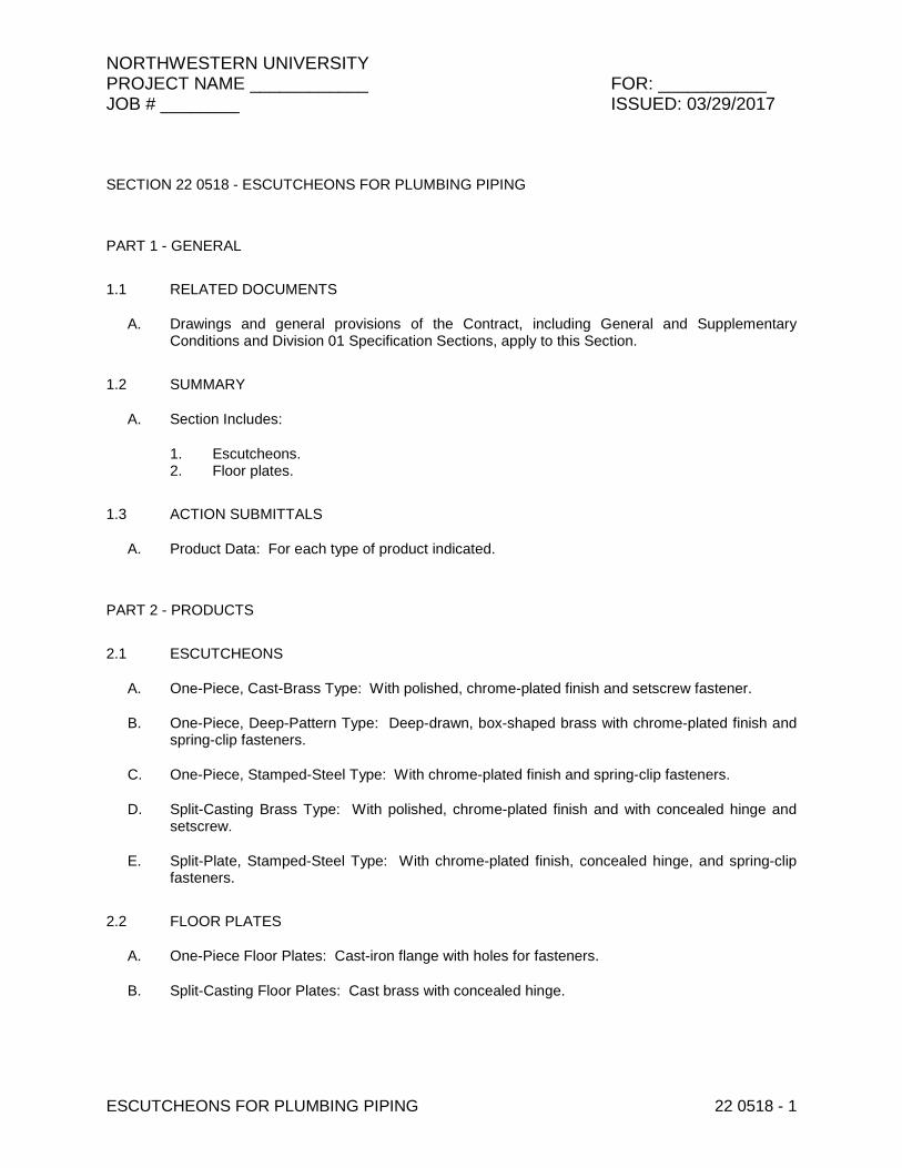
SECTION 22 0518 - ESCUTCHEONS FOR PLUMBING PIPING
PART 1 - GENERAL
1.1 RELATED DOCUMENTS
A. Drawings and general provisions of the Contract, including General and Supplementary Conditions and Division 01 Specification Sections, apply to this Section.
1.2 SUMMARY
A. Section Includes:
1. Escutcheons. 2. Floor plates.
1.3 ACTION SUBMITTALS
A. Product Data: For each type of product indicated.
PART 2 - PRODUCTS
2.1 ESCUTCHEONS
A. One-Piece, Cast-Brass Type: With polished, chrome-plated finish and setscrew fastener.
B. One-Piece, Deep-Pattern Type: Deep-drawn, box-shaped brass with chrome-plated finish and spring-clip fasteners.
C. One-Piece, Stamped-Steel Type: With chrome-plated finish and spring-clip fasteners.
D. Split-Casting Brass Type: With polished, chrome-plated finish and with concealed hinge and setscrew.
E. Split-Plate, Stamped-Steel Type: With chrome-plated finish, concealed hinge, and spring-clip fasteners.
2.2 FLOOR PLATES
A. One-Piece Floor Plates: Cast-iron flange with holes for fasteners.
B. Split-Casting Floor Plates: Cast brass with concealed hinge.

NORTHWESTERN UNIVERSITY PROJECT NAME ____________ FOR: ___________ JOB # ________ ISSUED: 03/29/2017
ESCUTCHEONS FOR PLUMBING PIPING 22 0518 - 2
PART 3 - EXECUTION
3.1 INSTALLATION
A. Install escutcheons for piping penetrations of walls, ceilings, and finished floors.
B. Install escutcheons with ID to closely fit around pipe, tube, and insulation of insulated piping and with OD that completely covers opening.
1. Escutcheons for New Piping:
a. Piping with Fitting or Sleeve Protruding from Wall: One-piece, deep-pattern type. b. Chrome-Plated Piping: One-piece, cast-brass type with polished, chrome-plated
finish. c. Insulated Piping: One-piece, stamped-steel type or split-plate, stamped-steel type
with concealed hinge. d. Bare Piping at Wall and Floor Penetrations in Finished Spaces: One-piece, cast-
brass type with polished, chrome-plated finish. e. Bare Piping at Ceiling Penetrations in Finished Spaces: One-piece, cast-brass
type with polished, chrome-plated finish. f. Bare Piping in Unfinished Service Spaces: One-piece, cast-brass or split-casting
brass type with polished, chrome-plated finish. g. Bare Piping in Equipment Rooms: One-piece, cast-brass or split-casting brass
type with polished, chrome-plated finish.
C. Install floor plates for piping penetrations of equipment-room floors.
D. Install floor plates with ID to closely fit around pipe, tube, and insulation of piping and with OD that completely covers opening.
1. New Piping: One-piece, floor-plate type. 2. Existing Piping: Split-casting, floor-plate type.
3.2 FIELD QUALITY CONTROL
A. Replace broken and damaged escutcheons and floor plates using new materials.
END OF SECTION 22 0518
NORTHWESTERN UNIVERSITY PROJECT NAME ____________ FOR: ___________ JOB # ________ ISSUED: 03/29/2017
METERS AND GAGES FOR PLUMBING PIPING 22 0519- 1
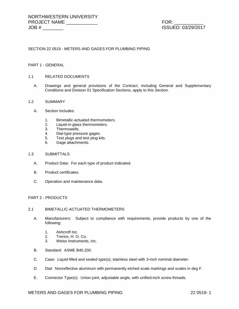
SECTION 22 0519 - METERS AND GAGES FOR PLUMBING PIPING
PART 1 - GENERAL
1.1 RELATED DOCUMENTS
A. Drawings and general provisions of the Contract, including General and Supplementary Conditions and Division 01 Specification Sections, apply to this Section.
1.2 SUMMARY
A. Section Includes:
1. Bimetallic-actuated thermometers. 2. Liquid-in-glass thermometers. 3. Thermowells. 4. Dial-type pressure gages. 5. Test plugs and test plug kits. 6. Gage attachments.
1.3 SUBMITTALS
A. Product Data: For each type of product indicated.
B. Product certificates.
C. Operation and maintenance data.
PART 2 - PRODUCTS
2.1 BIMETALLIC-ACTUATED THERMOMETERS
A. Manufacturers: Subject to compliance with requirements, provide products by one of the following:
1. Ashcroft Inc. 2. Trerice, H. O. Co. 3. Weiss Instruments, Inc.
B. Standard: ASME B40.200.
C. Case: Liquid-filled and sealed type(s); stainless steel with 3-inch nominal diameter.
D. Dial: Nonreflective aluminum with permanently etched scale markings and scales in deg F.
E. Connector Type(s): Union joint, adjustable angle, with unified-inch screw threads.

NORTHWESTERN UNIVERSITY PROJECT NAME ____________ FOR: ___________ JOB # ________ ISSUED: 03/29/2017
METERS AND GAGES FOR PLUMBING PIPING 22 0519- 2
F. Connector Size: 1/2 inch, with ASME B1.1 screw threads.
G. Stem: 0.25 or 0.375 inch in diameter; stainless steel.
H. Window: Plain glass.
I. Ring: Stainless steel.
J. Element: Bimetal coil.
K. Pointer: Dark-colored metal.
L. Accuracy: Plus or minus 1 percent of scale range.
2.2 LIQUID-IN-GLASS THERMOMETERS
A. Metal-Case, Industrial-Style, Liquid-in-Glass Thermometers:
1. Manufacturers: Subject to compliance with requirements, provide products by one of the following:
a. Trerice, H. O. Co. b. Weiss Instruments, Inc. c. Winters Instruments - U.S.
2. Standard: ASME B40.200. 3. Case: Cast aluminum; 9-inch nominal size unless otherwise indicated. 4. Case Form: Adjustable angle unless otherwise indicated. 5. Tube: Glass with magnifying lens and blue or red organic liquid. 6. Tube Background: Nonreflective aluminum with permanently etched scale markings
graduated in deg F. 7. Window: Glass. 8. Stem: Aluminum and of length to suit installation.
a. Design for Thermowell Installation: Bare stem.
9. Connector: 1-1/4 inches, with ASME B1.1 screw threads. 10. Accuracy: Plus or minus 1 percent of scale range or one scale division, to a maximum of
1.5 percent of scale range.
B. Plastic-Case, Industrial-Style, Liquid-in-Glass Thermometers:
1. Manufacturers: Subject to compliance with requirements, provide products by one of the following:
a. Ernst Flow Industries. b. Watts Regulator Co.; a div. of Watts Water Technologies, Inc. c. Weiss Instruments, Inc.
2. Standard: ASME B40.200. 3. Case: Plastic; 9-inch nominal size unless otherwise indicated. 4. Case Form: Adjustable angle unless otherwise indicated. 5. Tube: Glass with magnifying lens and blue or red organic liquid.
NORTHWESTERN UNIVERSITY PROJECT NAME ____________ FOR: ___________ JOB # ________ ISSUED: 03/29/2017
METERS AND GAGES FOR PLUMBING PIPING 22 0519- 3
6. Tube Background: Nonreflective aluminum with permanently etched scale markings graduated in deg F.
7. Window: Glass. 8. Stem: Aluminum and of length to suit installation.
a. Design for Thermowell Installation: Bare stem.
9. Connector: 1-1/4 inches, with ASME B1.1 screw threads. 10. Accuracy: Plus or minus 1 percent of scale range or one scale division, to a maximum of
1.5 percent of scale range.
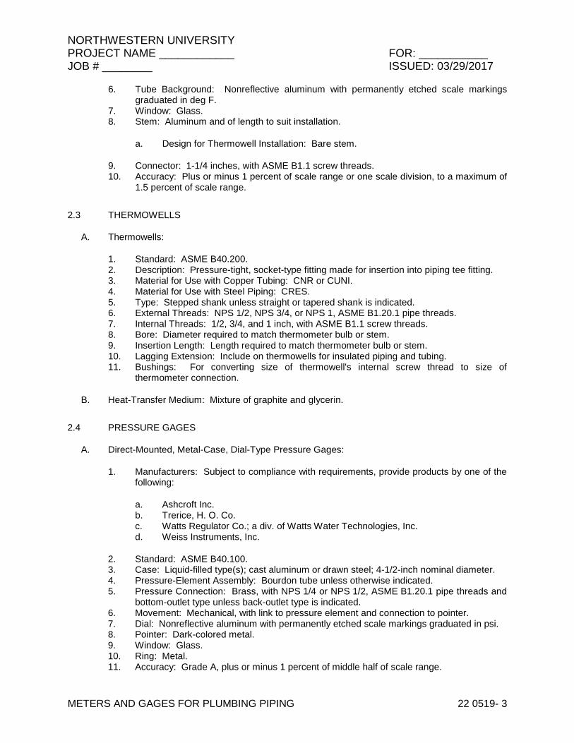
2.3 THERMOWELLS
A. Thermowells:
1. Standard: ASME B40.200. 2. Description: Pressure-tight, socket-type fitting made for insertion into piping tee fitting. 3. Material for Use with Copper Tubing: CNR or CUNI. 4. Material for Use with Steel Piping: CRES. 5. Type: Stepped shank unless straight or tapered shank is indicated. 6. External Threads: NPS 1/2, NPS 3/4, or NPS 1, ASME B1.20.1 pipe threads. 7. Internal Threads: 1/2, 3/4, and 1 inch, with ASME B1.1 screw threads. 8. Bore: Diameter required to match thermometer bulb or stem. 9. Insertion Length: Length required to match thermometer bulb or stem. 10. Lagging Extension: Include on thermowells for insulated piping and tubing. 11. Bushings: For converting size of thermowell's internal screw thread to size of
thermometer connection.
B. Heat-Transfer Medium: Mixture of graphite and glycerin.
2.4 PRESSURE GAGES
A. Direct-Mounted, Metal-Case, Dial-Type Pressure Gages:
1. Manufacturers: Subject to compliance with requirements, provide products by one of the following:
a. Ashcroft Inc. b. Trerice, H. O. Co. c. Watts Regulator Co.; a div. of Watts Water Technologies, Inc. d. Weiss Instruments, Inc.
2. Standard: ASME B40.100. 3. Case: Liquid-filled type(s); cast aluminum or drawn steel; 4-1/2-inch nominal diameter. 4. Pressure-Element Assembly: Bourdon tube unless otherwise indicated. 5. Pressure Connection: Brass, with NPS 1/4 or NPS 1/2, ASME B1.20.1 pipe threads and
bottom-outlet type unless back-outlet type is indicated. 6. Movement: Mechanical, with link to pressure element and connection to pointer. 7. Dial: Nonreflective aluminum with permanently etched scale markings graduated in psi. 8. Pointer: Dark-colored metal. 9. Window: Glass. 10. Ring: Metal. 11. Accuracy: Grade A, plus or minus 1 percent of middle half of scale range.
NORTHWESTERN UNIVERSITY PROJECT NAME ____________ FOR: ___________ JOB # ________ ISSUED: 03/29/2017
METERS AND GAGES FOR PLUMBING PIPING 22 0519- 4
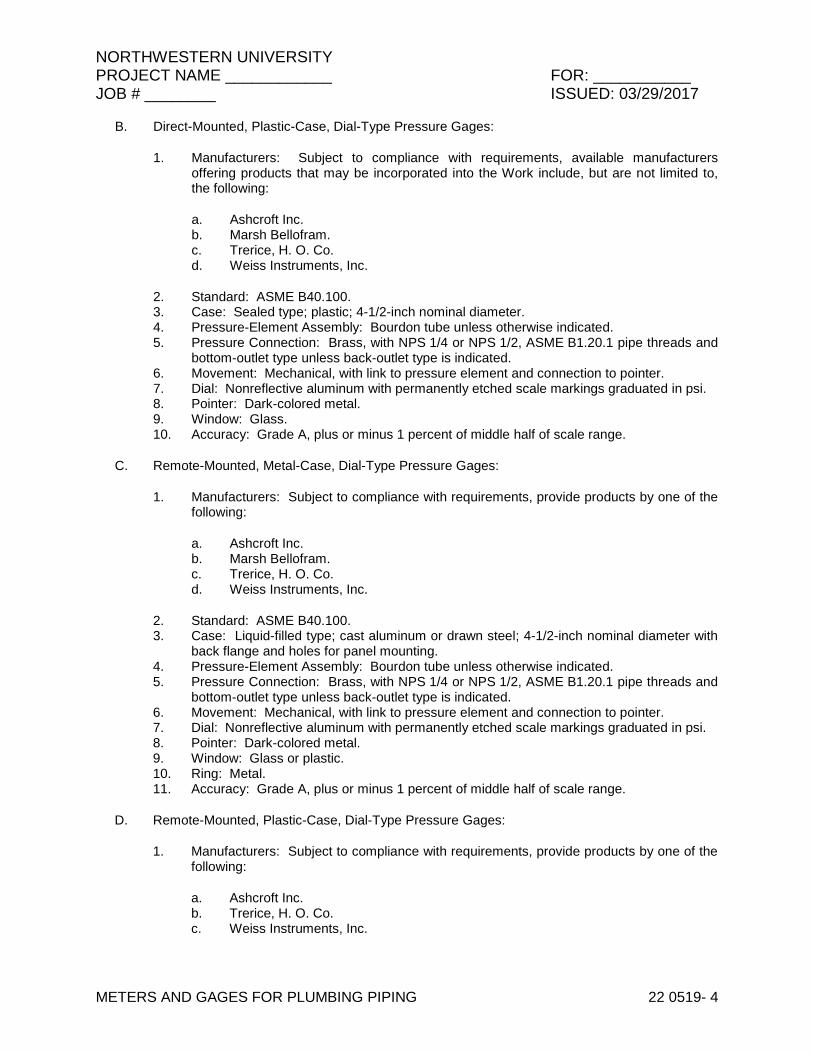
B. Direct-Mounted, Plastic-Case, Dial-Type Pressure Gages:
1. Manufacturers: Subject to compliance with requirements, available manufacturers offering products that may be incorporated into the Work include, but are not limited to, the following:
a. Ashcroft Inc. b. Marsh Bellofram. c. Trerice, H. O. Co. d. Weiss Instruments, Inc.
2. Standard: ASME B40.100. 3. Case: Sealed type; plastic; 4-1/2-inch nominal diameter. 4. Pressure-Element Assembly: Bourdon tube unless otherwise indicated. 5. Pressure Connection: Brass, with NPS 1/4 or NPS 1/2, ASME B1.20.1 pipe threads and
bottom-outlet type unless back-outlet type is indicated. 6. Movement: Mechanical, with link to pressure element and connection to pointer. 7. Dial: Nonreflective aluminum with permanently etched scale markings graduated in psi. 8. Pointer: Dark-colored metal. 9. Window: Glass. 10. Accuracy: Grade A, plus or minus 1 percent of middle half of scale range.
C. Remote-Mounted, Metal-Case, Dial-Type Pressure Gages:
1. Manufacturers: Subject to compliance with requirements, provide products by one of the following:
a. Ashcroft Inc. b. Marsh Bellofram. c. Trerice, H. O. Co. d. Weiss Instruments, Inc.
2. Standard: ASME B40.100. 3. Case: Liquid-filled type; cast aluminum or drawn steel; 4-1/2-inch nominal diameter with
back flange and holes for panel mounting. 4. Pressure-Element Assembly: Bourdon tube unless otherwise indicated. 5. Pressure Connection: Brass, with NPS 1/4 or NPS 1/2, ASME B1.20.1 pipe threads and
bottom-outlet type unless back-outlet type is indicated. 6. Movement: Mechanical, with link to pressure element and connection to pointer. 7. Dial: Nonreflective aluminum with permanently etched scale markings graduated in psi. 8. Pointer: Dark-colored metal. 9. Window: Glass or plastic. 10. Ring: Metal. 11. Accuracy: Grade A, plus or minus 1 percent of middle half of scale range.
D. Remote-Mounted, Plastic-Case, Dial-Type Pressure Gages:
1. Manufacturers: Subject to compliance with requirements, provide products by one of the following:
a. Ashcroft Inc. b. Trerice, H. O. Co. c. Weiss Instruments, Inc.

NORTHWESTERN UNIVERSITY PROJECT NAME ____________ FOR: ___________ JOB # ________ ISSUED: 03/29/2017
METERS AND GAGES FOR PLUMBING PIPING 22 0519- 5
2. Standard: ASME B40.100. 3. Case: Sealed type; plastic; 4-1/2-inch nominal diameter with back flange and holes for
panel mounting. 4. Pressure-Element Assembly: Bourdon tube unless otherwise indicated. 5. Pressure Connection: Brass, with NPS 1/4 or NPS 1/2, ASME B1.20.1 pipe threads and
bottom-outlet type unless back-outlet type is indicated. 6. Movement: Mechanical, with link to pressure element and connection to pointer. 7. Dial: Nonreflective aluminum with permanently etched scale markings graduated in psi. 8. Pointer: Dark-colored metal. 9. Window: Glass or plastic. 10. Accuracy: Grade A, plus or minus 1 percent of middle half of scale range.
2.5 TEST PLUGS
A. Manufacturers: Subject to compliance with requirements, provide products by one of the following:
1. Flow Design, Inc. 2. Miljoco Corporation. 3. National Meter, Inc. 4. Peterson Equipment Co., Inc. 5. Sisco Manufacturing Company, Inc. 6. Trerice, H. O. Co. 7. Watts Regulator Co.; a div. of Watts Water Technologies, Inc. 8. Weiss Instruments, Inc.
B. Description: Test-station fitting made for insertion into piping tee fitting.
C. Body: Stainless steel with core inserts and gasketed and threaded cap. Include extended stem on units to be installed in insulated piping.
D. Thread Size: NPS 1/4 (DN 8) or NPS 1/2 (DN 15), ASME B1.20.1 pipe thread.
E. Minimum Pressure and Temperature Rating: 500 psig at 200 deg F (3450 kPa at 93 deg C).
F. Core Inserts: Chlorosulfonated polyethylene synthetic and EPDM or neoprene or Nordel, but all potable water rated.
2.6 TEST-PLUG KITS
A. Manufacturers: Subject to compliance with requirements, provide products by one of the following:
1. Flow Design, Inc. 2. Miljoco Corporation. 3. National Meter, Inc. 4. Peterson Equipment Co., Inc. 5. Sisco Manufacturing Company, Inc. 6. Trerice, H. O. Co. 7. Watts Regulator Co.; a div. of Watts Water Technologies, Inc. 8. Weiss Instruments, Inc.

NORTHWESTERN UNIVERSITY PROJECT NAME ____________ FOR: ___________ JOB # ________ ISSUED: 03/29/2017
METERS AND GAGES FOR PLUMBING PIPING 22 0519- 6
B. Furnish two test-plug kit(s) containing two thermometer(s), one pressure gage and adapter, and carrying case. Thermometer sensing elements, pressure gage, and adapter probes shall be of diameter to fit test plugs and of length to project into piping.
C. Low-Range Thermometer: Small, bimetallic insertion type with 1- to 2-inch- (25- to 51-mm-) diameter dial and tapered-end sensing element. Dial range shall be at least 25 to 125 deg F (minus 4 to plus 52 deg C).
D. High-Range Thermometer: Small, bimetallic insertion type with 1- to 2-inch- (25- to 51-mm-) diameter dial and tapered-end sensing element. Dial range shall be at least 0 to 220 deg F (minus 18 to plus 104 deg C).
E. Pressure Gage: Small, Bourdon-tube insertion type with 2- to 3-inch- (51- to 76-mm-) diameter dial and probe. Dial range shall be at least 0 to 200 psig (0 to 1380 kPa).
F. Carrying Case: Metal or plastic, with formed instrument padding.
2.7 GAGE ATTACHMENTS
A. Snubbers: ASME B40.100, brass; with NPS 1/4 or NPS 1/2, ASME B1.20.1 pipe threads and piston-type surge-dampening device. Include extension for use on insulated piping.
B. Valves: Brass or stainless-steel needle, with NPS 1/4 or NPS 1/2, ASME B1.20.1 pipe threads.
PART 3 - EXECUTION
3.1 INSTALLATION
A. Install thermowells with socket extending a minimum of 2 inches into fluid and in vertical position in piping tees.
B. Install thermowells of sizes required to match thermometer connectors. Include bushings if required to match sizes.
C. Install thermowells with extension on insulated piping.
D. Fill thermowells with heat-transfer medium.
E. Install direct-mounted thermometers in thermowells and adjust vertical and tilted positions.
F. Install remote-mounted thermometer bulbs in thermowells and install cases on panels; connect cases with tubing and support tubing to prevent kinks. Use minimum tubing length.
G. Install direct-mounted pressure gages in piping tees with pressure gage located on pipe at the most readable position.
H. Install remote-mounted pressure gages on panel.
I. Install valve and snubber in piping for each pressure gage for fluids.
J. Install thermometers in the following locations:

NORTHWESTERN UNIVERSITY PROJECT NAME ____________ FOR: ___________ JOB # ________ ISSUED: 03/29/2017
METERS AND GAGES FOR PLUMBING PIPING 22 0519- 7
1. Inlet and outlet of each water heater.
K. Install pressure gages in the following locations:
1. Building water service entrance into building. 2. Inlet and outlet of each pressure-reducing valve. 3. Suction and discharge of each domestic water pump.
L. Install meters and gages adjacent to machines and equipment to allow service and maintenance of meters, gages, machines, and equipment.
M. Adjust faces of meters and gages to proper angle for best visibility.
3.2 THERMOMETER SCHEDULE
A. Thermometers at inlet and outlet of each domestic water heater shall be one of the following:
1. Liquid-filled, bimetallic-actuated type. 2. Industrial-style, liquid-in-glass type.
B. Thermometer stems shall be of length to match thermowell insertion length.
3.3 THERMOMETER SCALE-RANGE SCHEDULE
A. Scale Range for Domestic Cold-Water Piping: 0 to 100 deg F.
B. Scale Range for Domestic Hot-Water Piping: 0 to 250 deg F.
3.4 PRESSURE-GAGE SCHEDULE
A. Pressure gages at discharge of each water service into building shall be one of the following:
1. Liquid-filled Sealed, direct-mounted, metal case. 2. Sealed, direct-mounted, plastic case.
B. Pressure gages at inlet and outlet of each water pressure-reducing valve shall be one of the following:
1. Liquid-filled Sealed Open-front, pressure-relief Solid-front, pressure-relief Insert type, direct-mounted, metal case.
2. Sealed, direct-mounted, plastic case.
C. Pressure gages at suction and discharge of each domestic water pump shall be one of the following:
1. Liquid-filled, -mounted, metal case. 2. Sealed, direct-mounted, plastic case.
3.5 PRESSURE-GAGE SCALE-RANGE SCHEDULE
A. Scale Range for Water Service Piping: 0 to 100 psi.
NORTHWESTERN UNIVERSITY PROJECT NAME ____________ FOR: ___________ JOB # ________ ISSUED: 03/29/2017
METERS AND GAGES FOR PLUMBING PIPING 22 0519- 8
B. Scale Range for Domestic Water Piping: 0 to 160 psi.
END OF SECTION 22 0519

NORTHWESTERN UNIVERSITY PROJECT NAME ____________ FOR: ___________ JOB # ________ ISSUED: 03/29/2017
GENERAL-DUTY VALVES FOR PLUMBING PIPING 22 0523 - 1
SECTION 22 0523 - GENERAL-DUTY VALVES FOR PLUMBING PIPING
PART 1 - GENERAL
1.1 RELATED DOCUMENTS
A. Drawings and general provisions of the Contract, including General and Supplementary Conditions and Division 01 Specification Sections, apply to this Section.
1.2 SUMMARY
A. Section Includes:
1. Bronze ball valves. 2. Bronze swing check valves. 3. Iron swing check valves. 4. Iron swing check valves with closure control. 5. Bronze globe valves. 6. Iron globe valves. 7. Chainwheels.
B. Related Sections:
1. Division 22 plumbing piping Sections for specialty valves applicable to those Sections only.
2. Division 22 Section "Identification for Plumbing Piping and Equipment" for valve tags and schedules.
3. Division 33 water distribution piping Sections for general-duty and specialty valves for site construction piping.
1.3 SUBMITTALS
A. Product Data: For each type of valve indicated.
1.4 QUALITY ASSURANCE
A. ASME Compliance: ASME B16.10 and ASME B16.34 for ferrous valve dimensions and design criteria.
B. NSF Compliance: NSF 61 for valve materials for potable-water service.
C. To assure uniformity and compatibility, all grooved end valves and adjoining couplings shall be supplied by the same manufacturer.

NORTHWESTERN UNIVERSITY PROJECT NAME ____________ FOR: ___________ JOB # ________ ISSUED: 03/29/2017
GENERAL-DUTY VALVES FOR PLUMBING PIPING 22 0523 - 2
PART 2 - PRODUCTS
2.1 GENERAL REQUIREMENTS FOR VALVES
A. Refer to valve schedule articles for applications of valves.
B. Valve Pressure and Temperature Ratings: Not less than indicated and as required for system pressures and temperatures.
C. Valve Sizes: Same as upstream piping unless otherwise indicated.
D. Valve Actuator Types:
1. Gear Actuator: For quarter-turn valves NPS 8 and larger. 2. Handwheel: For valves other than quarter-turn types. 3. Handlever: For quarter-turn valves NPS 6 and smaller except plug valves. 4. Chainwheel: Device for attachment to valve handwheel, stem, or other actuator; of size
and with chain for mounting height, as indicated in the "Valve Installation" Article.
E. Valves in Insulated Piping: With 2-1/4 inch stem extensions and the following features:
1. Ball Valves: With extended operating handle of non-thermal-conductive material, and protective sleeve that allows operation of valve without breaking the vapor seal or disturbing insulation.
F. Valve-End Connections:
1. Flanged: With flanges according to ASME B16.1 for iron valves. 2. Solder Joint: With sockets according to ASME B16.18. 3. Threaded: With threads according to ASME B1.20.1. 4. Grooved: With grooves according to ANSI/AWWA C606.
2.2 BRONZE BALL VALVES
A. Two-Piece, Full-Port, Ball Valves with Stainless-Steel Trim:
1. Manufacturers: Subject to compliance with requirements, provide products by one of the following:
a. Conbraco Industries, Inc. (Apollo)
2. Description:
a. Standard: MSS SP-110. b. SWP Rating: 150 psig. c. CWP Rating: 600 psig. d. Body Design: Two piece. e. Body Material: Bronze. f. Ends: Threaded. g. Seats: PTFE or TFE. h. Stem: 316 Stainless Steel. i. Ball: 316 Stainless Steel. j. Port: Full.

NORTHWESTERN UNIVERSITY PROJECT NAME ____________ FOR: ___________ JOB # ________ ISSUED: 03/29/2017
GENERAL-DUTY VALVES FOR PLUMBING PIPING 22 0523 - 3
2.3 BRONZE SWING CHECK VALVES
A. Class 125, Bronze Swing Check Valves with Bronze Disc:
1. Manufacturers: Subject to compliance with requirements, provide products by one of the following:
a. Conbraco Industries, Inc. (Apollo)
2. Description:
a. Standard: MSS SP-80, Type 3. b. CWP Rating: 200 psig. c. Body Design: Horizontal flow. d. Body Material: ASTM B 62, bronze. e. Ends: Threaded. f. Disc: Bronze.
2.4 IRON SWING CHECK VALVES
A. Class 125, Iron Swing Check Valves with Metal Seats:
1. Manufacturers: Subject to compliance with requirements, provide products by one of the following:
a. Conbraco Industries, Inc. (Apollo)
2. Description:
a. Standard: MSS SP-71, Type I. b. CWP Rating: 200 psig. c. Body Design: Clear or full waterway. d. Body Material: ASTM A 126, gray iron with bolted bonnet. e. Ends: Flanged. f. Trim: Bronze. g. Gasket: Asbestos free.
2.5 IRON SWING CHECK VALVES WITH CLOSURE CONTROL
A. Class 125, Iron Swing Check Valves with Lever- and Spring-Closure Control:
1. Description:
a. Standard: MSS SP-71, Type I. b. CWP Rating: 200 psig. c. Body Design: Clear or full waterway. d. Body Material: ASTM A 126, gray iron with bolted bonnet. e. Ends: Flanged. f. Trim: Bronze. g. Gasket: Asbestos free. h. Closure Control: Factory-installed, exterior lever and spring.
NORTHWESTERN UNIVERSITY PROJECT NAME ____________ FOR: ___________ JOB # ________ ISSUED: 03/29/2017
GENERAL-DUTY VALVES FOR PLUMBING PIPING 22 0523 - 4
2.6 BRONZE GLOBE VALVES
A. Class 125, Bronze Globe Valves with Bronze Disc:
1. Manufacturers: Subject to compliance with requirements, provide products by one of the following:
a. Conbraco Industries, Inc. (Apollo)
2. Description:
a. Standard: MSS SP-80, Type 1. b. CWP Rating: 200 psig. c. Body Material: ASTM B 62, bronze with integral seat and screw-in bonnet. d. Ends: Threaded or solder joint. e. Stem and Disc: Bronze. f. Packing: Asbestos free. g. Handwheel: Malleable iron.
2.7 IRON GLOBE VALVES
A. Class 125, Iron Globe Valves:
1. Manufacturers: Subject to compliance with requirements, provide products by one of the following:
a. Conbraco Industries, Inc. (Apollo)
2. Description:
a. Standard: MSS SP-85, Type I. b. CWP Rating: 200 psig. c. Body Material: ASTM A 126, gray iron with bolted bonnet. d. Ends: Flanged. e. Trim: Bronze. f. Packing and Gasket: Asbestos free.
2.8 CHAINWHEELS
A. Description: Valve actuation assembly with sprocket rim, brackets, and chain.
1. Brackets: Type, number, size, and fasteners required to mount actuator on valve. 2. Sprocket Rim with Chain Guides: Ductile iron, of type and size required for
valve. Include zinc coating. 3. Chain: Hot-dip, galvanized steel, of size required to fit sprocket rim.
NORTHWESTERN UNIVERSITY PROJECT NAME ____________ FOR: ___________ JOB # ________ ISSUED: 03/29/2017
GENERAL-DUTY VALVES FOR PLUMBING PIPING 22 0523 - 5
PART 3 - EXECUTION
3.1 VALVE INSTALLATION
A. Install valves with unions or flanges at each piece of equipment arranged to allow service, maintenance, and equipment removal without system shutdown.
B. Locate valves for easy access and provide separate support where necessary.
C. Install valves in horizontal piping with stem at or above center of pipe.
D. Install valves in position to allow full stem movement.
E. Install swing check valves for proper direction of flow and in horizontal position with hinge pin level.
F. Install grooved end valves in accordance with the manufacturer's guidelines and recommendations. A representative shall provide on-site training for contractor's field personnel in the installation of grooved end valves. Factory-trained representative shall periodically review the product installation. Contractor shall remove and replace any improperly installed products.
3.2 ADJUSTING
A. Adjust or replace valve packing after piping systems have been tested and put into service but before final adjusting and balancing. Replace valves if persistent leaking occurs.
3.3 GENERAL REQUIREMENTS FOR VALVE APPLICATIONS
A. If valve applications are not indicated, use the following:
1. Shutoff Service: Ball valves. 2. Throttling Service: Globe or ball valves. 3. Pump-Discharge Check Valves:
a. NPS 2 and Smaller: Bronze swing check valves with bronze or nonmetallic disc. b. NPS 2-1/2 and Larger for Domestic Water: Iron swing check valves with lever and
weight or with spring. c. NPS 2-1/2 and Larger for Sanitary Waste and Storm Drainage: Iron swing check
valves with lever and weight or spring.
B. If valves with specified SWP classes or CWP ratings are not available, the same types of valves with higher SWP class or CWP ratings may be substituted.
C. Select valves, except wafer types, with the following end connections:
1. For Copper Tubing, NPS 2 and Smaller: Threaded ends except where solder-joint valve-end option is indicated in valve schedules below.
2. For Copper Tubing, NPS 2-1/2 to NPS 4: Flanged ends except where threaded valve-end option is indicated in valve schedules below.
3. For Steel Piping, NPS 2 and Smaller: Threaded ends.

NORTHWESTERN UNIVERSITY PROJECT NAME ____________ FOR: ___________ JOB # ________ ISSUED: 03/29/2017
GENERAL-DUTY VALVES FOR PLUMBING PIPING 22 0523 - 6
4. For Steel Piping, NPS 2-1/2 to NPS 4: Flanged ends except where threaded valve-end option is indicated in valve schedules below.
3.4 DOMESTIC, HOT- AND COLD-WATER VALVE SCHEDULE
A. Pipe NPS 2 and Smaller:
1. Bronze Valves: May be provided with solder-joint ends instead of threaded ends. 2. Bronze Angle Valves: Class 125, bronze disc. 3. Ball Valves: Two piece, full port, 316 stainless steel with bronze trim. 4. Bronze Swing Check Valves: Class 125, bronze disc. 5. Bronze Globe Valves: Class 125, bronze disc.
B. Pipe NPS 2-1/2 and Larger:
1. Iron Valves, NPS 2-1/2 to NPS 4: May be provided with threaded ends instead of flanged ends.
2. Iron Swing Check Valves: Class 125, metal seats. 3. Iron Swing Check Valves with Closure Control: Class 125, lever and spring. 4. Iron Globe Valves: Class 125.
END OF SECTION 22 0523

NORTHWESTERN UNIVERSITY PROJECT NAME ____________ FOR: ___________ JOB # ________ ISSUED: 03/29/2017
GENERAL-DUTY VALVES FOR PLUMBING PIPING 22 0523 - 7
THIS PAGE IS INTENTIONALLY BLANK

NORTHWESTERN UNIVERSITY PROJECT NAME ____________ FOR: ___________ JOB # ________ ISSUED: 03/29/2017
HANGERS AND SUPPORTS FOR PLUMBING PIPING AND EQUIPMENT 22 0529 - 1
SECTION 22 0529 - HANGERS AND SUPPORTS FOR PLUMBING PIPING AND EQUIPMENT
PART 1 - GENERAL
1.1 RELATED DOCUMENTS
A. Drawings and general provisions of the Contract, including General and Supplementary Conditions and Division 01 Specification Sections, apply to this Section.
1.2 SUMMARY
A. Section Includes:
1. Metal pipe hangers and supports. 2. Trapeze pipe hangers. 3. Metal framing systems. 4. Thermal-hanger shield inserts. 5. Fastener systems. 6. Pipe stands. 7. Pipe positioning systems. 8. Equipment supports.
B. Related Sections:
1. Section 055000 "Metal Fabrications" for structural-steel shapes and plates for trapeze hangers for pipe and equipment supports.
2. Section 220516 "Expansion Fittings and Loops for Plumbing Piping" for pipe guides and anchors.
3. Section 220548 "Vibration and Seismic Controls for Plumbing Piping and Equipment" for vibration isolation devices.
1.3 DEFINITIONS
A. MSS: Manufacturers Standardization Society of The Valve and Fittings Industry Inc.
1.4 PERFORMANCE REQUIREMENTS
A. Delegated Design: Design trapeze pipe hangers and equipment supports, including comprehensive engineering analysis by a qualified professional engineer, using performance requirements and design criteria indicated.
B. Structural Performance: Hangers and supports for plumbing piping and equipment shall withstand the effects of gravity loads and stresses within limits and under conditions indicated according to ASCE/SEI 7.
1. Design supports for multiple pipes, including pipe stands, capable of supporting combined weight of supported systems, system contents, and test water.

NORTHWESTERN UNIVERSITY PROJECT NAME ____________ FOR: ___________ JOB # ________ ISSUED: 03/29/2017
HANGERS AND SUPPORTS FOR PLUMBING PIPING AND EQUIPMENT 22 0529 - 2
2. Design equipment supports capable of supporting combined operating weight of supported equipment and connected systems and components.
1.5 ACTION SUBMITTALS
A. Product Data: For each type of product indicated.
B. Shop Drawings: Show fabrication and installation details and include calculations for the following; include Product Data for components:
1. Trapeze pipe hangers. 2. Metal framing systems. 3. Pipe stands. 4. Equipment supports.
C. Delegated-Design Submittal: For trapeze hangers indicated to comply with performance requirements and design criteria, including analysis data signed and sealed by the qualified professional engineer responsible for their preparation.
1. Detail fabrication and assembly of trapeze hangers. 2. Design Calculations: Calculate requirements for designing trapeze hangers.
1.6 INFORMATIONAL SUBMITTALS
A. Welding certificates.
1.7 QUALITY ASSURANCE
A. Structural Steel Welding Qualifications: Qualify procedures and personnel according to AWS D1.1/D1.1M, "Structural Welding Code - Steel."
B. Pipe Welding Qualifications: Qualify procedures and operators according to ASME Boiler and Pressure Vessel Code.
PART 2 - PRODUCTS
2.1 METAL PIPE HANGERS AND SUPPORTS
A. Carbon-Steel Pipe Hangers and Supports:
1. Description: MSS SP-58, Types 1 through 58, factory-fabricated components. 2. Galvanized Metallic Coatings: Pre-galvanized or hot dipped. 3. Nonmetallic Coatings: Plastic coating, jacket, or liner. 4. Padded Hangers: Hanger with fiberglass or other pipe insulation pad or cushion to
support bearing surface of piping. 5. Hanger Rods: Continuous-thread rod, nuts, and washer made of carbon steel.
B. Stainless-Steel Pipe Hangers and Supports:
1. Description: MSS SP-58, Types 1 through 58, factory-fabricated components.

NORTHWESTERN UNIVERSITY PROJECT NAME ____________ FOR: ___________ JOB # ________ ISSUED: 03/29/2017
HANGERS AND SUPPORTS FOR PLUMBING PIPING AND EQUIPMENT 22 0529 - 3
2. Padded Hangers: Hanger with fiberglass or other pipe insulation pad or cushion to support bearing surface of piping.
3. Hanger Rods: Continuous-thread rod, nuts, and washer made of stainless steel.
C. Copper Pipe Hangers:
1. Description: MSS SP-58, Types 1 through 58, copper-coated-steel, factory-fabricated components.
2. Hanger Rods: Continuous-thread rod, nuts, and washer made of copper-coated steel or stainless steel.
2.2 TRAPEZE PIPE HANGERS
A. Description: MSS SP-69, Type 59, shop- or field-fabricated pipe-support assembly made from structural carbon-steel shapes with MSS SP-58 carbon-steel hanger rods, nuts, saddles, and U-bolts.
2.3 METAL FRAMING SYSTEMS
A. MFMA Manufacturer Metal Framing Systems:
1. Manufacturers: Subject to compliance with requirements, provide products by one of the following:
a. Allied Tube & Conduit. b. Cooper B-Line, Inc. c. Powerstrut d. Unistrut Corporation; Tyco International, Ltd.
2. Description: Shop- or field-fabricated pipe-support assembly for supporting multiple parallel pipes.
3. Standard: MFMA-4. 4. Channels: Continuous slotted steel channel with inturned lips. 5. Channel Nuts: Formed or stamped steel nuts or other devices designed to fit into
channel slot and, when tightened, prevent slipping along channel. 6. Hanger Rods: Continuous-thread rod, nuts, and washers made of carbon steel. 7. Metallic Coating: Electroplated zinc or mill galvanized.
2.4 THERMAL-HANGER SHIELD INSERTS
A. Manufacturers: Subject to compliance with requirements, provide products by one of the following:
1. Carpenter & Paterson, Inc. 2. Clement Support Services. 3. ERICO International Corporation. 4. National Pipe Hanger Corporation. 5. PHS Industries, Inc. 6. Pipe Shields, Inc.; a subsidiary of Piping Technology & Products, Inc. 7. Piping Technology & Products, Inc. 8. Rilco Manufacturing Co., Inc. 9. Value Engineered Products, Inc.
NORTHWESTERN UNIVERSITY PROJECT NAME ____________ FOR: ___________ JOB # ________ ISSUED: 03/29/2017
HANGERS AND SUPPORTS FOR PLUMBING PIPING AND EQUIPMENT 22 0529 - 4
B. Insulation-Insert Material for Cold Piping: ASTM C 552, Type II cellular glass with 100-psig (688-kPa) or ASTM C 591, Type VI, Grade 1 polyisocyanurate with 125-psig (862-kPa) minimum compressive strength and vapor barrier.
C. Insulation-Insert Material for Hot Piping: Water-repellent treated, ASTM C 533, Type I calcium silicate with 100-psig (688-kPa), ASTM C 552, Type II cellular glass with 100-psig (688-kPa), or ASTM C 591, Type VI, Grade 1 polyisocyanurate with 125-psig (862-kPa) minimum compressive strength.
D. For Trapeze or Clamped Systems: Insert and shield shall cover entire circumference of pipe.
E. For Clevis or Band Hangers: Insert and shield shall cover lower 180 degrees of pipe.
F. Insert Length: Extend 2 inches (50 mm) beyond sheet metal shield for piping operating below ambient air temperature.
2.5 FASTENER SYSTEMS
A. Mechanical-Expansion Anchors: Insert-wedge-type, zinc-coated steel anchors, for use in hardened portland cement concrete; with pull-out, tension, and shear capacities appropriate for supported loads and building materials where used.
2.6 PIPE STANDS
A. General Requirements for Pipe Stands: Shop- or field-fabricated assemblies made of manufactured corrosion-resistant components to support roof-mounted piping.
B. Compact Pipe Stand: One-piece plastic unit with integral-rod roller, pipe clamps, or V-shaped cradle to support pipe, for roof installation without membrane penetration.
C. Low-Type, Single-Pipe Stand: One-piece stainless-steel base unit with plastic roller, for roof installation without membrane penetration.
D. High-Type, Single-Pipe Stand:
1. Description: Assembly of base, vertical and horizontal members, and pipe support, for roof installation without membrane penetration.
2. Base: Stainless steel. 3. Vertical Members: Two or more cadmium-plated-steel or stainless-steel, continuous-
thread rods. 4. Horizontal Member: Cadmium-plated-steel or stainless-steel rod with plastic or stainless-
steel, roller-type pipe support.
E. High-Type, Multiple-Pipe Stand:
1. Description: Assembly of bases, vertical and horizontal members, and pipe supports, for roof installation without membrane penetration.
2. Bases: One or more; plastic. 3. Vertical Members: Two or more protective-coated-steel channels. 4. Horizontal Member: Protective-coated-steel channel. 5. Pipe Supports: Galvanized-steel, clevis-type pipe hangers.
NORTHWESTERN UNIVERSITY PROJECT NAME ____________ FOR: ___________ JOB # ________ ISSUED: 03/29/2017
HANGERS AND SUPPORTS FOR PLUMBING PIPING AND EQUIPMENT 22 0529 - 5
F. Curb-Mounting-Type Pipe Stands: Shop- or field-fabricated pipe supports made from structural-steel shapes, continuous-thread rods, and rollers, for mounting on permanent stationary roof curb.
2.7 PIPE POSITIONING SYSTEMS
A. Description: IAPMO PS 42, positioning system of metal brackets, clips, and straps for positioning piping in pipe spaces; for plumbing fixtures in commercial applications.
2.8 EQUIPMENT SUPPORTS
A. Description: Welded, shop- or field-fabricated equipment support made from structural carbon-steel shapes.
2.9 MISCELLANEOUS MATERIALS
A. Structural Steel: ASTM A 36/A 36M, carbon-steel plates, shapes, and bars; black and galvanized.
B. Grout: ASTM C 1107, factory-mixed and -packaged, dry, hydraulic-cement, nonshrink and nonmetallic grout; suitable for interior and exterior applications.
1. Properties: Nonstaining, noncorrosive, and nongaseous. 2. Design Mix: 5000-psi (34.5-MPa), 28-day compressive strength.
PART 3 - EXECUTION
3.1 HANGER AND SUPPORT INSTALLATION
A. Metal Pipe-Hanger Installation: Comply with MSS SP-69 and MSS SP-89. Install hangers, supports, clamps, and attachments as required to properly support piping from the building structure.
B. Metal Trapeze Pipe-Hanger Installation: Comply with MSS SP-69 and MSS SP-89. Arrange for grouping of parallel runs of horizontal piping, and support together on field-fabricated trapeze pipe hangers.
1. Pipes of Various Sizes: Support together and space trapezes for smallest pipe size or install intermediate supports for smaller diameter pipes as specified for individual pipe hangers.
2. Field fabricate from ASTM A 36/A 36M, carbon-steel shapes selected for loads being supported. Weld steel according to AWS D1.1/D1.1M.
C. Metal Framing System Installation: Arrange for grouping of parallel runs of piping, and support together on field-assembled metal framing systems.
D. Thermal-Hanger Shield Installation: Install in pipe hanger or shield for insulated piping.
E. Fastener System Installation:

NORTHWESTERN UNIVERSITY PROJECT NAME ____________ FOR: ___________ JOB # ________ ISSUED: 03/29/2017
HANGERS AND SUPPORTS FOR PLUMBING PIPING AND EQUIPMENT 22 0529 - 6
1. Install mechanical-expansion anchors in concrete after concrete is placed and completely cured. Install fasteners according to manufacturer's written instructions.
F. Pipe Stand Installation:
1. Pipe Stand Types except Curb-Mounted Type: Assemble components and mount on smooth roof surface. Do not penetrate roof membrane.
2. Curb-Mounted-Type Pipe Stands: Assemble components or fabricate pipe stand and mount on permanent, stationary roof curb. See Section 077200 "Roof Accessories" for curbs.
G. Pipe Positioning-System Installation: Install support devices to make rigid supply and waste piping connections to each plumbing fixture.
H. Install hangers and supports complete with necessary attachments, inserts, bolts, rods, nuts, washers, and other accessories.
I. Equipment Support Installation: Fabricate from welded-structural-steel shapes.
J. Install hangers and supports to allow controlled thermal and seismic movement of piping systems, to permit freedom of movement between pipe anchors, and to facilitate action of expansion joints, expansion loops, expansion bends, and similar units.
K. Install lateral bracing with pipe hangers and supports to prevent swaying.
L. Install building attachments within concrete slabs or attach to structural steel. Install additional attachments at concentrated loads, including valves, flanges, and strainers, NPS 2-1/2 (DN 65) and larger and at changes in direction of piping. Install concrete inserts before concrete is placed; fasten inserts to forms and install reinforcing bars through openings at top of inserts.
M. Load Distribution: Install hangers and supports so that piping live and dead loads and stresses from movement will not be transmitted to connected equipment.
N. Pipe Slopes: Install hangers and supports to provide indicated pipe slopes and to not exceed maximum pipe deflections allowed by ASME B31.9 for building services piping.
O. Insulated Piping:
1. Attach clamps and spacers to piping.
a. Piping Operating above Ambient Air Temperature: Clamp may project through insulation.
b. Piping Operating below Ambient Air Temperature: Use thermal-hanger shield insert with clamp sized to match OD of insert.
c. Do not exceed pipe stress limits allowed by ASME B31.9 for building services piping.
2. Install MSS SP-58, Type 39, protection saddles if insulation without vapor barrier is indicated. Fill interior voids with insulation that matches adjoining insulation.
a. Option: Thermal-hanger shield inserts may be used. Include steel weight-distribution plate for pipe NPS 4 (DN 100) and larger if pipe is installed on rollers.
NORTHWESTERN UNIVERSITY PROJECT NAME ____________ FOR: ___________ JOB # ________ ISSUED: 03/29/2017
HANGERS AND SUPPORTS FOR PLUMBING PIPING AND EQUIPMENT 22 0529 - 7
3. Install MSS SP-58, Type 40, protective shields on cold piping with vapor barrier. Shields shall span an arc of 180 degrees.
a. Option: Thermal-hanger shield inserts may be used. Include steel weight-distribution plate for pipe NPS 4 (DN 100) and larger if pipe is installed on rollers.
4. Shield Dimensions for Pipe: Not less than the following:
a. NPS 1/4 to NPS 3-1/2 (DN 8 to DN 90): 12 inches (305 mm) long and 0.048 inch (1.22 mm) thick.
b. NPS 4 (DN 100): 12 inches (305 mm) long and 0.06 inch (1.52 mm) thick. c. NPS 5 and NPS 6 (DN 125 and DN 150): 18 inches (457 mm) long and 0.06 inch
(1.52 mm) thick. d. NPS 8 to NPS 14 (DN 200 to DN 350): 24 inches (610 mm) long and 0.075 inch
(1.91 mm) thick. e. NPS 16 to NPS 24 (DN 400 to DN 600): 24 inches (610 mm) long and 0.105 inch
(2.67 mm) thick.
5. Pipes NPS 8 (DN 200) and Larger: Include wood or reinforced calcium-silicate-insulation inserts of length at least as long as protective shield.
6. Thermal-Hanger Shields: Install with insulation same thickness as piping insulation.
3.2 EQUIPMENT SUPPORTS
A. Fabricate structural-steel stands to suspend equipment from structure overhead or to support equipment above floor.
B. Grouting: Place grout under supports for equipment and make bearing surface smooth.
C. Provide lateral bracing, to prevent swaying, for equipment supports.
3.3 METAL FABRICATIONS
A. Cut, drill, and fit miscellaneous metal fabrications for trapeze pipe hangers and equipment supports.
B. Fit exposed connections together to form hairline joints. Field weld connections that cannot be shop welded because of shipping size limitations.
C. Field Welding: Comply with AWS D1.1/D1.1M procedures for shielded, metal arc welding; appearance and quality of welds; and methods used in correcting welding work; and with the following:
1. Use materials and methods that minimize distortion and develop strength and corrosion resistance of base metals.
2. Obtain fusion without undercut or overlap. 3. Remove welding flux immediately. 4. Finish welds at exposed connections so no roughness shows after finishing and so
contours of welded surfaces match adjacent contours.
NORTHWESTERN UNIVERSITY PROJECT NAME ____________ FOR: ___________ JOB # ________ ISSUED: 03/29/2017
HANGERS AND SUPPORTS FOR PLUMBING PIPING AND EQUIPMENT 22 0529 - 8
3.4 ADJUSTING
A. Hanger Adjustments: Adjust hangers to distribute loads equally on attachments and to achieve indicated slope of pipe.
B. Trim excess length of continuous-thread hanger and support rods to 1-1/2 inches (40 mm).
3.5 PAINTING
A. Touchup: Clean field welds and abraded areas of shop paint. Paint exposed areas immediately after erecting hangers and supports. Use same materials as used for shop painting. Comply with SSPC-PA 1 requirements for touching up field-painted surfaces.
1. Apply paint by brush or spray to provide a minimum dry film thickness of 2.0 mils (0.05 mm).
B. Touchup: Cleaning and touchup painting of field welds, bolted connections, and abraded areas of shop paint on miscellaneous metal are specified in applicable Division 9 section(s).
C. Galvanized Surfaces: Clean welds, bolted connections, and abraded areas and apply galvanizing-repair paint to comply with ASTM A 780.
3.6 HANGER AND SUPPORT SCHEDULE
A. Specific hanger and support requirements are in Sections specifying piping systems and equipment.
B. Comply with MSS SP-69 for pipe-hanger selections and applications that are not specified in piping system Sections.
C. Use hangers and supports with galvanized metallic coatings for piping and equipment that will not have field-applied finish.
D. Use nonmetallic coatings on attachments for electrolytic protection where attachments are in direct contact with copper tubing.
E. Use carbon-steel pipe hangers and supports, metal trapeze pipe hangers, and metal framing systems and attachments for general service applications.
F. Use stainless-steel pipe hangers and stainless-steel attachments for hostile environment applications.
G. Use copper-plated pipe hangers and copper or stainless-steel attachments for copper piping and tubing.
H. Use padded hangers for piping that is subject to scratching.
I. Use thermal-hanger shield inserts for insulated piping and tubing.
J. Horizontal-Piping Hangers and Supports: Unless otherwise indicated and except as specified in piping system Sections, install the following types:

NORTHWESTERN UNIVERSITY PROJECT NAME ____________ FOR: ___________ JOB # ________ ISSUED: 03/29/2017
HANGERS AND SUPPORTS FOR PLUMBING PIPING AND EQUIPMENT 22 0529 - 9
1. Adjustable, Steel Clevis Hangers (MSS Type 1): For suspension of non-insulated or insulated, stationary pipes NPS 1/2 to NPS 30 (DN 15 to DN 750).
2. Yoke-Type Pipe Clamps (MSS Type 2): For suspension of up to 1050 deg F (566 deg C), pipes NPS 4 to NPS 24 (DN 100 to DN 600), requiring up to 4 inches (100 mm) of insulation.
3. Carbon- or Alloy-Steel, Double-Bolt Pipe Clamps (MSS Type 3): For suspension of pipes NPS 3/4 to NPS 36 (DN 20 to DN 900), requiring clamp flexibility and up to 4 inches (100 mm) of insulation.
4. Steel Pipe Clamps (MSS Type 4): For suspension of cold and hot pipes NPS 1/2 to NPS 24 (DN 15 to DN 600) if little or no insulation is required.
5. Pipe Hangers (MSS Type 5): For suspension of pipes NPS 1/2 to NPS 4 (DN 15 to DN 100), to allow off-center closure for hanger installation before pipe erection.
6. Adjustable, Swivel Split- or Solid-Ring Hangers (MSS Type 6): For suspension of noninsulated, stationary pipes NPS 3/4 to NPS 8 (DN 20 to DN 200).
7. Adjustable, Steel Band Hangers (MSS Type 7): For suspension of noninsulated, stationary pipes NPS 1/2 to NPS 8 (DN 15 to DN 200).
8. Adjustable Band Hangers (MSS Type 9): For suspension of noninsulated, stationary pipes NPS 1/2 to NPS 8 (DN 15 to DN 200).
9. Adjustable, Swivel-Ring Band Hangers (MSS Type 10): For suspension of noninsulated, stationary pipes NPS 1/2 to NPS 8 (DN 15 to DN 200).
10. Split Pipe Ring with or without Turnbuckle Hangers (MSS Type 11): For suspension of noninsulated, stationary pipes NPS 3/8 to NPS 8 (DN 10 to DN 200).
11. Extension Hinged or Two-Bolt Split Pipe Clamps (MSS Type 12): For suspension of noninsulated, stationary pipes NPS 3/8 to NPS 3 (DN 10 to DN 80).
12. U-Bolts (MSS Type 24): For support of heavy pipes NPS 1/2 to NPS 30 (DN 15 to DN 750).
13. Clips (MSS Type 26): For support of insulated pipes not subject to expansion or contraction.
14. Pipe Saddle Supports (MSS Type 36): For support of pipes NPS 4 to NPS 36 (DN 100 to DN 900), with steel-pipe base stanchion support and cast-iron floor flange or carbon-steel plate.
15. Pipe Stanchion Saddles (MSS Type 37): For support of pipes NPS 4 to NPS 36 (DN 100 to DN 900), with steel-pipe base stanchion support and cast-iron floor flange or carbon-steel plate, and with U-bolt to retain pipe.
16. Adjustable Pipe Saddle Supports (MSS Type 38): For stanchion-type support for pipes NPS 2-1/2 to NPS 36 (DN 65 to DN 900) if vertical adjustment is required, with steel-pipe base stanchion support and cast-iron floor flange.
17. Single-Pipe Rolls (MSS Type 41): For suspension of pipes NPS 1 to NPS 30 (DN 25 to DN 750), from two rods if longitudinal movement caused by expansion and contraction might occur.
18. Adjustable Roller Hangers (MSS Type 43): For suspension of pipes NPS 2-1/2 to NPS 24 (DN 65 to DN 600), from single rod if horizontal movement caused by expansion and contraction might occur.
19. Complete Pipe Rolls (MSS Type 44): For support of pipes NPS 2 to NPS 42 (DN 50 to DN 1050) if longitudinal movement caused by expansion and contraction might occur but vertical adjustment is not necessary.
20. Pipe Roll and Plate Units (MSS Type 45): For support of pipes NPS 2 to NPS 24 (DN 50 to DN 600) if small horizontal movement caused by expansion and contraction might occur and vertical adjustment is not necessary.
21. Adjustable Pipe Roll and Base Units (MSS Type 46): For support of pipes NPS 2 to NPS 30 (DN 50 to DN 750) if vertical and lateral adjustment during installation might be required in addition to expansion and contraction.
NORTHWESTERN UNIVERSITY PROJECT NAME ____________ FOR: ___________ JOB # ________ ISSUED: 03/29/2017
HANGERS AND SUPPORTS FOR PLUMBING PIPING AND EQUIPMENT 22 0529 - 10
K. Vertical-Piping Clamps: Unless otherwise indicated and except as specified in piping system Sections, install the following types:
1. Extension Pipe or Riser Clamps (MSS Type 8): For support of pipe risers NPS 3/4 to NPS 24 (DN 24 to DN 600).
2. Carbon- or Alloy-Steel Riser Clamps (MSS Type 42): For support of pipe risers NPS 3/4 to NPS 24 (DN 20 to DN 600) if longer ends are required for riser clamps.
L. Hanger-Rod Attachments: Unless otherwise indicated and except as specified in piping system Sections, install the following types:
1. Steel Turnbuckles (MSS Type 13): For adjustment up to 6 inches (150 mm) for heavy loads.
2. Steel Clevises (MSS Type 14): For 120 to 450 deg F (49 to 232 deg C) piping installations.
3. Swivel Turnbuckles (MSS Type 15): For use with MSS Type 11, split pipe rings. 4. Malleable-Iron Sockets (MSS Type 16): For attaching hanger rods to various types of
building attachments. 5. Steel Weldless Eye Nuts (MSS Type 17): For 120 to 450 deg F (49 to 232 deg C) piping
installations.
M. Building Attachments: Unless otherwise indicated and except as specified in piping system Sections, install the following types:
1. Steel or Malleable Concrete Inserts (MSS Type 18): For upper attachment to suspend pipe hangers from concrete ceiling.
2. Top-Beam C-Clamps (MSS Type 19): For use under roof installations with bar-joist construction, to attach to top flange of structural shape.
3. Side-Beam or Channel Clamps (MSS Type 20): For attaching to bottom flange of beams, channels, or angles.
4. Center-Beam Clamps (MSS Type 21): For attaching to center of bottom flange of beams. 5. Welded Beam Attachments (MSS Type 22): For attaching to bottom of beams if loads
are considerable and rod sizes are large. 6. C-Clamps (MSS Type 23): For structural shapes. 7. Top-Beam Clamps (MSS Type 25): For top of beams if hanger rod is required tangent to
flange edge. 8. Side-Beam Clamps (MSS Type 27): For bottom of steel I-beams. 9. Steel-Beam Clamps with Eye Nuts (MSS Type 28): For attaching to bottom of steel I-
beams for heavy loads. 10. Linked-Steel Clamps with Eye Nuts (MSS Type 29): For attaching to bottom of steel I-
beams for heavy loads, with link extensions. 11. Malleable-Beam Clamps with Extension Pieces (MSS Type 30): For attaching to
structural steel. 12. Welded-Steel Brackets: For support of pipes from below or for suspending from above
by using clip and rod. Use one of the following for indicated loads:
a. Light (MSS Type 31): 750 lb (340 kg). b. Medium (MSS Type 32): 1500 lb (680 kg). c. Heavy (MSS Type 33): 3000 lb (1360 kg).
13. Side-Beam Brackets (MSS Type 34): For sides of steel or wooden beams. 14. Plate Lugs (MSS Type 57): For attaching to steel beams if flexibility at beam is required. 15. Horizontal Travelers (MSS Type 58): For supporting piping systems subject to linear
horizontal movement where headroom is limited.

NORTHWESTERN UNIVERSITY PROJECT NAME ____________ FOR: ___________ JOB # ________ ISSUED: 03/29/2017
HANGERS AND SUPPORTS FOR PLUMBING PIPING AND EQUIPMENT 22 0529 - 11
N. Saddles and Shields: Unless otherwise indicated and except as specified in piping system Sections, install the following types:
1. Steel-Pipe-Covering Protection Saddles (MSS Type 39): To fill interior voids with insulation that matches adjoining insulation.
2. Protection Shields (MSS Type 40): Of length recommended in writing by manufacturer to prevent crushing insulation.
3. Thermal-Hanger Shield Inserts: For supporting insulated pipe.
O. Spring Hangers and Supports: Unless otherwise indicated and except as specified in piping system Sections, install the following types:
1. Restraint-Control Devices (MSS Type 47): Where indicated to control piping movement. 2. Spring Cushions (MSS Type 48): For light loads if vertical movement does not exceed 1-
1/4 inches (32 mm). 3. Spring-Cushion Roll Hangers (MSS Type 49): For equipping Type 41, roll hanger with
springs. 4. Spring Sway Braces (MSS Type 50): To retard sway, shock, vibration, or thermal
expansion in piping systems. 5. Variable-Spring Hangers (MSS Type 51): Preset to indicated load and limit variability
factor to 25 percent to allow expansion and contraction of piping system from hanger. 6. Variable-Spring Base Supports (MSS Type 52): Preset to indicated load and limit
variability factor to 25 percent to allow expansion and contraction of piping system from base support.
7. Variable-Spring Trapeze Hangers (MSS Type 53): Preset to indicated load and limit variability factor to 25 percent to allow expansion and contraction of piping system from trapeze support.
8. Constant Supports: For critical piping stress and if necessary to avoid transfer of stress from one support to another support, critical terminal, or connected equipment. Include auxiliary stops for erection, hydrostatic test, and load-adjustment capability. These supports include the following types:
a. Horizontal (MSS Type 54): Mounted horizontally. b. Vertical (MSS Type 55): Mounted vertically. c. Trapeze (MSS Type 56): Two vertical-type supports and one trapeze member.
P. Comply with MSS SP-69 for trapeze pipe-hanger selections and applications that are not specified in piping system Sections.
Q. Comply with MFMA-103 for metal framing system selections and applications that are not specified in piping system Sections.

NORTHWESTERN UNIVERSITY PROJECT NAME ____________ FOR: ___________ JOB # ________ ISSUED: 03/29/2017
HANGERS AND SUPPORTS FOR PLUMBING PIPING AND EQUIPMENT 22 0529 - 12
R. Use mechanical-expansion anchors instead of building attachments where required in concrete construction.
S. Use pipe positioning systems in pipe spaces behind plumbing fixtures to support supply and waste piping for plumbing fixtures.
END OF SECTION 22 0529

NORTHWESTERN UNIVERSITY PROJECT NAME ____________ FOR: ___________ JOB # ________ ISSUED: 03/29/2017
VIBRATION AND SEISMIC CONTROLS FOR PLUMBING PIPING AND EQUIPMENT 22 0548 - 1
SECTION 22 0548 - VIBRATION AND SEISMIC CONTROLS FOR PLUMBING PIPING AND EQUIPMENT
PART 1 - GENERAL
1.1 RELATED DOCUMENTS
A. Drawings and general provisions of the Contract, including General and Supplementary Conditions and Division 01 Specification Sections, apply to this Section.
1.2 SUMMARY
A. This Section includes the following:
1. Isolation pads. 2. Isolation mounts. 3. Freestanding spring isolators. 4. Housed spring mounts. 5. Elastomeric hangers. 6. Spring hangers. 7. Spring hangers with vertical-limit stops. 8. Pipe riser resilient supports. 9. Resilient pipe guides.
1.3 DEFINITIONS
A. IBC: International Building Code.
B. ICC-ES: ICC-Evaluation Service.
C. OSHPD: Office of Statewide Health Planning and Development for the State of California.
1.4 ACTION SUBMITTALS
A. Product Data: For the following:
1. Include rated load, rated deflection, and overload capacity for each vibration isolation device.
B. Delegated-Design Submittal: For vibration isolation details indicated to comply with performance requirements and design criteria, including analysis data signed and sealed by the qualified professional engineer responsible for their preparation.
1. Riser Supports: Include riser diagrams and calculations showing anticipated expansion and contraction at each support point, initial and final loads on building structure, spring deflection changes, and seismic loads. Include certification that riser system has been examined for excessive stress and that none will exist.
NORTHWESTERN UNIVERSITY PROJECT NAME ____________ FOR: ___________ JOB # ________ ISSUED: 03/29/2017
VIBRATION AND SEISMIC CONTROLS FOR PLUMBING PIPING AND EQUIPMENT 22 0548 - 2
1.5 INFORMATIONAL SUBMITTALS
A. Qualification Data: For professional engineer and testing agency.
B. Welding certificates.
C. Field quality-control test reports.
1.6 QUALITY ASSURANCE
A. Testing Agency Qualifications: An independent agency, with the experience and capability to conduct the testing indicated, that is a nationally recognized testing laboratory (NRTL) as defined by OSHA in 29 CFR 1910.7, and that is acceptable to authorities having jurisdiction.
B. Welding: Qualify procedures and personnel according to AWS D1.1/D1.1M, "Structural Welding Code - Steel."
PART 2 - PRODUCTS
2.1 VIBRATION ISOLATORS
A. Manufacturers: Subject to compliance with requirements, provide products by one of the following:
1. Kinetics Noise Control. 2. Mason Industries. 3. Vibro-Acoustics.
B. Pads: Arranged in single or multiple layers of sufficient stiffness for uniform loading over pad area, molded with a nonslip pattern and galvanized-steel baseplates, and factory cut to sizes that match requirements of supported equipment.
1. Resilient Material: Oil- and water-resistant neoprene or rubber.
C. Mounts: Double-deflection type, with molded, oil-resistant rubber, hermetically sealed compressed fiberglass, or neoprene isolator elements with factory-drilled, encapsulated top plate for bolting to equipment and with baseplate for bolting to structure. Color-code or otherwise identify to indicate capacity range.
1. Materials: Cast-ductile-iron or welded steel housing containing two separate and opposing, oil-resistant rubber or neoprene elements that prevent central threaded element and attachment hardware from contacting the housing during normal operation.
2. Neoprene: Shock-absorbing materials compounded according to the standard for bridge-bearing neoprene as defined by AASHTO.
D. Spring Isolators: Freestanding, laterally stable, open-spring isolators.
1. Outside Spring Diameter: Not less than 80 percent of the compressed height of the spring at rated load.
2. Minimum Additional Travel: 50 percent of the required deflection at rated load. 3. Lateral Stiffness: More than 80 percent of rated vertical stiffness.

NORTHWESTERN UNIVERSITY PROJECT NAME ____________ FOR: ___________ JOB # ________ ISSUED: 03/29/2017
VIBRATION AND SEISMIC CONTROLS FOR PLUMBING PIPING AND EQUIPMENT 22 0548 - 3
4. Overload Capacity: Support 200 percent of rated load, fully compressed, without deformation or failure.
5. Baseplates: Factory drilled for bolting to structure and bonded to 1/4-inch- (6-mm-) thick, rubber isolator pad attached to baseplate underside. Baseplates shall limit floor load to 500 psig (3447 kPa).
6. Top Plate and Adjustment Bolt: Threaded top plate with adjustment bolt and cap screw to fasten and level equipment.
E. Housed Spring Mounts: Housed spring isolator.
1. Housing: Ductile-iron or steel housing. 2. Base: Factory drilled for bolting to structure. 3. Snubbers: Vertically adjustable to allow a maximum of 1/4-inch (6-mm) travel up or down
before contacting a resilient collar.
F. Elastomeric Hangers: Single or double-deflection type, fitted with molded, oil-resistant elastomeric isolator elements bonded to steel housings with threaded connections for hanger rods. Color-code or otherwise identify to indicate capacity range.
G. Spring Hangers: Combination coil-spring and elastomeric-insert hanger with spring and insert in compression.
1. Frame: Steel, fabricated for connection to threaded hanger rods and to allow for a maximum of 30 degrees of angular hanger-rod misalignment without binding or reducing isolation efficiency.
2. Outside Spring Diameter: Not less than 80 percent of the compressed height of the spring at rated load.
3. Minimum Additional Travel: 50 percent of the required deflection at rated load. 4. Lateral Stiffness: More than 80 percent of rated vertical stiffness. 5. Overload Capacity: Support 200 percent of rated load, fully compressed, without
deformation or failure. 6. Elastomeric Element: Molded, oil-resistant rubber or neoprene. Steel-washer-reinforced
cup to support spring and bushing projecting through bottom of frame. 7. Self-centering hanger rod cap to ensure concentricity between hanger rod and support
spring coil.
H. Spring Hangers with Vertical-Limit Stop: Combination coil-spring and elastomeric-insert hanger with spring and insert in compression and with a vertical-limit stop.
1. Frame: Steel, fabricated for connection to threaded hanger rods and to allow for a maximum of 30 degrees of angular hanger-rod misalignment without binding or reducing isolation efficiency.
2. Outside Spring Diameter: Not less than 80 percent of the compressed height of the spring at rated load.
3. Minimum Additional Travel: 50 percent of the required deflection at rated load. 4. Lateral Stiffness: More than 80 percent of rated vertical stiffness. 5. Overload Capacity: Support 200 percent of rated load, fully compressed, without
deformation or failure. 6. Elastomeric Element: Molded, oil-resistant rubber or neoprene. 7. Adjustable Vertical Stop: Steel washer with neoprene washer "up-stop" on lower
threaded rod. 8. Self-centering hanger rod cap to ensure concentricity between hanger rod and support
spring coil.
NORTHWESTERN UNIVERSITY PROJECT NAME ____________ FOR: ___________ JOB # ________ ISSUED: 03/29/2017
VIBRATION AND SEISMIC CONTROLS FOR PLUMBING PIPING AND EQUIPMENT 22 0548 - 4
I. Pipe Riser Resilient Support: All-directional, acoustical pipe anchor consisting of 2 steel tubes separated by a minimum of 1/2-inch- (13-mm-) thick neoprene. Include steel and neoprene vertical-limit stops arranged to prevent vertical travel in both directions. Design support for a maximum load on the isolation material of 500 psig (3.45 MPa) and for equal resistance in all directions.
J. Resilient Pipe Guides: Telescopic arrangement of 2 steel tubes or post and sleeve arrangement separated by a minimum of 1/2-inch- (13-mm-) thick neoprene. Where clearances are not readily visible, a factory-set guide height with a shear pin to allow vertical motion due to pipe expansion and contraction shall be fitted. Shear pin shall be removable and reinsertable to allow for selection of pipe movement. Guides shall be capable of motion to meet location requirements.
2.2 FACTORY FINISHES
A. Finish: Manufacturer's standard paint applied to factory-assembled and -tested equipment before shipping.
1. Powder coating on springs and housings. 2. All hardware shall be galvanized. Hot-dip galvanize metal components for exterior use. 3. Baked enamel or powder coat for metal components on isolators for interior use. 4. Color-code or otherwise mark vibration isolation and seismic-control devices to indicate
capacity range.
PART 3 - EXECUTION
3.1 EXAMINATION
A. Examine areas and equipment to receive vibration isolation for compliance with requirements for installation tolerances and other conditions affecting performance.
B. Examine roughing-in of reinforcement and cast-in-place anchors to verify actual locations before installation.
C. Proceed with installation only after unsatisfactory conditions have been corrected.
3.2 APPLICATIONS
A. Multiple Pipe Supports: Secure pipes to trapeze member with clamps approved for application by an evaluation service member of ICC-ES, OSHPD, or an agency acceptable to authorities having jurisdiction.
B. Hanger Rod Stiffeners: Install hanger rod stiffeners where indicated or scheduled on Drawings to receive them and where required to prevent buckling of hanger rods due to seismic forces.
C. Strength of Support Assemblies: Where not indicated, select sizes of components so strength will be adequate to carry present and future static loads within specified loading limits.

NORTHWESTERN UNIVERSITY PROJECT NAME ____________ FOR: ___________ JOB # ________ ISSUED: 03/29/2017
VIBRATION AND SEISMIC CONTROLS FOR PLUMBING PIPING AND EQUIPMENT 22 0548 - 5
3.3 VIBRATION-CONTROL DEVICE INSTALLATION
A. Equipment Restraints:
1. Install resilient bolt isolation washers on equipment anchor bolts where clearance between anchor and adjacent surface exceeds 0.125 inches (3.2 mm).
B. Install cables so they do not bend across edges of adjacent equipment or building structure.
C. Install bushing assemblies for anchor bolts for floor-mounted equipment, arranged to provide resilient media between anchor bolt and mounting hole in concrete base.
D. Install bushing assemblies for mounting bolts for wall-mounted equipment, arranged to provide resilient media where equipment or equipment-mounting channels are attached to wall.
E. Attachment to Structure: If specific attachment is not indicated, anchor bracing to structure at flanges of beams, at upper truss chords of bar joists, or at concrete members.
F. Drilled-in Anchors:
1. Identify position of reinforcing steel and other embedded items prior to drilling holes for anchors. Do not damage existing reinforcing or embedded items during coring or drilling. Notify the structural engineer if reinforcing steel or other embedded items are encountered during drilling. Locate and avoid prestressed tendons, electrical and telecommunications conduit, and gas lines.
2. Do not drill holes in concrete or masonry until concrete, mortar, or grout has achieved full design strength.
3. Wedge Anchors: Protect threads from damage during anchor installation. Heavy-duty sleeve anchors shall be installed with sleeve fully engaged in the structural element to which anchor is to be fastened.
4. Adhesive Anchors: Clean holes to remove loose material and drilling dust prior to installation of adhesive. Place adhesive in holes proceeding from the bottom of the hole and progressing toward the surface in such a manner as to avoid introduction of air pockets in the adhesive.
5. Set anchors to manufacturer's recommended torque, using a torque wrench. 6. Install zinc-coated steel anchors for interior and stainless steel anchors for exterior
applications.
3.4 FIELD QUALITY CONTROL
A. Testing Agency: Northwestern University will engage a qualified testing agency to perform tests and inspections.
B. Tests and Inspections:
1. Provide evidence of recent calibration of test equipment by a testing agency acceptable to authorities having jurisdiction.
2. Schedule test with Northwestern University, through Architect, before connecting anchorage device to restrained component (unless post connection testing has been approved), and with at least seven days' advance notice.
3. Obtain Architect's approval before transmitting test loads to structure. Provide temporary load-spreading members.

NORTHWESTERN UNIVERSITY PROJECT NAME ____________ FOR: ___________ JOB # ________ ISSUED: 03/29/2017
VIBRATION AND SEISMIC CONTROLS FOR PLUMBING PIPING AND EQUIPMENT 22 0548 - 6
4. Test at least four of each type and size of installed anchors and fasteners selected by Architect.
5. Test to 90 percent of rated proof load of device. 6. Measure isolator deflection. 7. Test and adjust air-mounting system controls and safeties. 8. If a device fails test, modify all installations of same type and retest until satisfactory
results are achieved.
C. Remove and replace malfunctioning units and retest as specified above.
D. Prepare test and inspection reports.
3.5 ADJUSTING
A. Adjust isolators after piping system is at operating weight.
B. Adjust limit stops on restrained spring isolators to mount equipment at normal operating height. After equipment installation is complete, adjust limit stops so they are out of contact during normal operation.
C. Adjust active height of sprint isolators.
D. Adjust restraints to permit free movement of equipment within normal mode of operation.
END OF SECTION 22 0548

NORTHWESTERN UNIVERSITY PROJECT NAME ____________ FOR: ___________ JOB # ________ ISSUED: 03/29/2017
IDENTIFICATION FOR PLUMBING PIPING AND EQUIPMENT 22 0553 - 1
SECTION 22 0553 - IDENTIFICATION FOR PLUMBING PIPING AND EQUIPMENT
PART 1 - GENERAL
1.1 RELATED DOCUMENTS
A. Drawings and general provisions of the Contract, including General and Supplementary Conditions and Division 01 Specification Sections, apply to this Section.
1.2 SUMMARY
A. Section Includes:
1. Equipment labels. 2. Pipe labels. 3. Valve tags. 4. Warning tags.
1.3 ACTION SUBMITTALS
A. Product Data: For each type of product indicated.
B. Samples: For color, letter style, and graphic representation required for each identification material and device.
C. Equipment Label Schedule: Include a listing of all equipment to be labeled with the proposed content for each label.
D. Valve numbering scheme.
E. Valve Schedules: For each piping system to include in maintenance manuals.
1.4 COORDINATION
A. Coordinate installation of identifying devices with completion of covering and painting of surfaces where devices are to be applied.
B. Coordinate installation of identifying devices with locations of access panels and doors.
C. Install identifying devices before installing acoustical ceilings and similar concealment.
1.5 WORK INCLUDED
A. Furnish and install nameplates, valve tags, valve charts, and pipe markers on all Plumbing equipment, and piping.
B. Provide nameplates with the unit number and service designation on all plumbing equipment.

NORTHWESTERN UNIVERSITY PROJECT NAME ____________ FOR: ___________ JOB # ________ ISSUED: 03/29/2017
IDENTIFICATION FOR PLUMBING PIPING AND EQUIPMENT 22 0553 - 2
C. Indicate all valve tag numbers on Record Drawings and submit framed under glass valve tag charts including valve service and location.
D. Install color coded ceiling tacks in acoustical tile ceilings or color coded tape on ceiling grid to identify location of equipment, valves and dampers that require regular maintenance or are part of a life safety system (fire dampers, smoke dampers, sprinkler valves or main isolation valves). Concealed fire protection valves shall be marked by red label triangles (3" equilateral) and circle dots (1" diameter). Triangles shall be placed on the wall nearest the valve with the apex pointing toward the ceiling tile. Dots shall be placed on border of ceiling tile.
E. Provide underground plastic pipe markers 6 to 8 inches below finish grade, directly above buried pipes.
F. Prepare valve charts and frame under glass. All valves and the tag numbers shall be shown on the Record As-Built Drawings.
G. Provide valve computer data base to match chart.
H. Prepare and install exterior protected brass plaques indicating underground service entrances.
PART 2 - PRODUCTS
2.1 GENERAL
A. Acceptable manufactures contingent on compliance with the specification.
1. Seton 2. Brady Corporation 3. Marking Services Incorporated
2.2 EQUIPMENT NAMEPLATES
A. Equipment nameplates shall be 3” x 6” long, 0.02” aluminum with a black enamel background with engraved natural aluminum letters similar to Seton Style 2065-20. Nameplate shall have pressure sensitive taped backing.
B. The nameplate shall contain the unit or equipment designation (“AHU” for air handling unit, “P” for circulating pump, etc.), unit number and area or system served.
C. Nameplates for exterior equipment shall be applied with waterproof adhesive.
2.3 PIPE IDENTIFICATION AND VALVE TAGS
A. All piping, except that piping which is within inaccessible chases, shall be identified with semi-rigid plastic identification markers equal to Seton Setmark pipe markers.
1. Direction of flow arrows are to be included on each marker. 2. Each marker background shall be appropriately color coded with a clearly printed legend
to identify the contents of the pipe in conformance with the “Scheme for the Identification of Piping Systems” (ASME A13.1-1981).
NORTHWESTERN UNIVERSITY PROJECT NAME ____________ FOR: ___________ JOB # ________ ISSUED: 03/29/2017
IDENTIFICATION FOR PLUMBING PIPING AND EQUIPMENT 22 0553 - 3
3. Setmark snap-around markers shall be used for overall diameters up to 6” and strap-around markers shall be used above 6” overall diameters.
4. Markers shall be located:
a. Adjacent to each valve b. At each branch c. At each cap for future d. At each riser takeoff, e. At each pipe passage through wall (each side) f. At each pipe passage at 20’ – 0” intervals maximum. g. At each piece of equipment. h. At all access doors. i. A minimum of one (1) marker shall be provided at each room.
5. Under ground pipe markers:
a. Provide detectable tape on all underground piping: b. Labels shall be color coded and labeled the same as indoors.
B. Valve tags
1. All valves shall be designated by distinguishing numbers and letters carefully coordinated with a valve chart. Valve tags shall include what room(s) the valve serves and piece of equipment served.
2. Valve tags shall be color coded 0.032” anodized aluminum tags, with engraved letters similar to Seton S Type 250-BL or approved equal.
a. HVAC tags shall be round 2” diameter, similar to Seton 15426. b. Plumbing tags shall be square 2” x 2” similar to Seton 42769. c. Fire Protection tags shall be square 2” x 2” similar to Seton 42769 RED. d. Lettering shall be ¼” high for type service and ½” for valve number. Tag shall
indicate service and valve number. e. Each service shall be a different color.
3. Tag shall be attached to valves with chain similar to Seton No 16 stainless steel jack chain.
4. Whenever a valve is above a hung ceiling, the valve tag shall be located immediately above the hung ceiling.
5. Provide a tag for every valve except:
a. Perimeter radiation shut-off valves that are located at the finned tube radiation element within the accessible (from the space) heating enclosure
C. Furnish a minimum of two (2) typed valve lists
1. Each framed under glass or Plexiglas. Each chart shall be enclosed in an approved 0.015” thick plastic closure for permanent protection.
2. Valve numbers shall correspond to those indicated on the Record Drawings and on the printed valve lists.
3. The printed list shall include the valve number, location and purpose of each valve. 4. It shall state other necessary information such as the required opening or closing of
another valve when one valve is to be opened or closed. 5. Printed framed valve lists shall be displayed in each Mechanical Room or in a location
designated by Northwestern University.
NORTHWESTERN UNIVERSITY PROJECT NAME ____________ FOR: ___________ JOB # ________ ISSUED: 03/29/2017
IDENTIFICATION FOR PLUMBING PIPING AND EQUIPMENT 22 0553 - 4
D. Valve data base.
1. Provide a valve data base for all valves to operate on the building computer. 2. Every valve shall include:
a. Tag Number b. Service (Hot water, Chilled water, Sprinkler, etc.) c. Size d. Operation e. Location f. Manufacture g. Model number h. Submittal reference
2.4 UTILITY ENTRANCE DESIGNATIONS
A. Provide a brass wall plaque, minimum 0.020” thickness, secured to the exterior wall just above the grade line for all buried service entrances or exits. Samples are: Water Service Below; Gas Service Below; Sanitary Sewer Below; Storm Sewer Below; Irrigation Water Below; etc.
B. Ceiling Tacks or Tape.
C. Provide steel color coded 3/4 inch diameter ceiling tacks in acoustical tile ceilings or color coded tape applied to ceiling grid to locate equipment, valves or dampers that require regular maintenance or are part of a Life Safety System.
D. The tacks or tapes shall be color codes as follows:
1. Yellow – HVAC 2. Red – Life Safety (fire dampers, sprinkler valves, etc.) 3. Green - Plumbing Valves. 4. Blue – Heating/Cooling Valves.
PART 3 - EXECUTION
3.1 PREPARATION
A. All surfaces shall be cleaned and insulated (if applicable) prior to installing any identification.
B. Exterior surfaces of outdoor equipment shall be dry and prepared to accept the specified identification.
3.2 INSTALLATION
A. Install nameplates with corrosive-resistant mechanical fasteners, or adhesive. Apply with sufficient adhesive to ensure permanent adhesion. Seal with clear lacquer.
B. Install valve tags with chain.
C. Install plastic pipe markers in accordance with manufacturer’s Instructions.

NORTHWESTERN UNIVERSITY PROJECT NAME ____________ FOR: ___________ JOB # ________ ISSUED: 03/29/2017
IDENTIFICATION FOR PLUMBING PIPING AND EQUIPMENT 22 0553 - 5
D. Install plastic tape markers complete around pipe in accordance with manufacturer’s instructions.
E. Install underground plastic pipe markers 6 to 8 inches below finished grade, directly above buried pipe.
F. Identify air handling units, pumps, domestic hot water heaters, fire pumps, heat transfer equipment tanks, water treatment devices, etc. with plastic nameplates. Small devices, such as in-line pumps, may be identified with tags.
G. Identify control panels and major control components outside panels with plastic nameplates.
H. Install detector tape on all under ground services in accordance with the manufactures recommendations.
I. Identify thermostats relating to air handling equipment serving multiple spaces.
J. Identify valves in main and branch piping with valve tags.
K. Tag automatic controls, instruments and relays. Key to control schematic.
L. Identify piping, concealed or exposed, with pipe markers or where buried using plastic tape pipe markers. Use tags on piping ¾ inch diameter and smaller. Identify service, flow direction and pressure. Install in clear view and align with axis of piping. Locate identification not to exceed 20 feet on straight runs including risers and drops, adjacent to each valve and Tee, at each side of penetration of structure or enclosure, and at each obstruction.
END OF SECTION 22 0553
NORTHWESTERN UNIVERSITY PROJECT NAME ____________ FOR: ___________ JOB # ________ ISSUED: 03/29/2017
IDENTIFICATION FOR PLUMBING PIPING AND EQUIPMENT 22 0553 - 6
THIS PAGE IS INTENTIONALLY BLANK

NORTHWESTERN UNIVERSITY PROJECT NAME ____________ FOR: ___________ JOB # ________ ISSUED: 03/29/2017
PLUMBING INSULATION 22 0700 - 1
SECTION 220700 - PLUMBING INSULATION
PART 1 - GENERAL
1.1 RELATED DOCUMENTS
A. Drawings and general provisions of the Contract, including General and Supplementary Conditions and Division 01 Specification Sections, apply to this Section.
1.2 SUMMARY
A. Section Includes:
1. Insulation Materials:
a. Flexible elastomeric. b. Mineral fiber. c. Polyolefin.
2. Insulating cements. 3. Adhesives. 4. Mastics. 5. Sealants. 6. Factory-applied jackets. 7. Field-applied fabric-reinforcing mesh. 8. Field-applied jackets. 9. Tapes. 10. Securements. 11. Corner angles.
B. Related Sections include the following:
1. Division 23 Section "HVAC Insulation."
1.3 SUBMITTALS
A. Product Data: For each type of product indicated.
B. LEED Submittal:
1. Product Data for Credit EQ 4.1: For adhesives and sealants, including printed statement of VOC content.
C. Shop Drawings:
1. Detail application of protective shields, saddles, and inserts at hangers for each type of insulation and hanger.
2. Detail attachment and covering of heat tracing inside insulation.
NORTHWESTERN UNIVERSITY PROJECT NAME ____________ FOR: ___________ JOB # ________ ISSUED: 03/29/2017
PLUMBING INSULATION 22 0700 - 2
3. Detail insulation application at pipe expansion joints for each type of insulation. 4. Detail insulation application at elbows, fittings, flanges, valves, and specialties for each
type of insulation. 5. Detail removable insulation at piping specialties, equipment connections, and access
panels. 6. Detail application of field-applied jackets. 7. Detail application at linkages of control devices. 8. Detail field application for each equipment type.
D. Field quality-control reports.
1.4 QUALITY ASSURANCE
A. Fire-Test-Response Characteristics: Insulation and related materials shall have fire-test-response characteristics indicated, as determined by testing identical products per ASTM E 84, by a testing and inspecting agency acceptable to authorities having jurisdiction. Factory label insulation and jacket materials and adhesive, mastic, tapes, and cement material containers, with appropriate markings of applicable testing and inspecting agency.
1. Insulation Installed Indoors: Flame-spread index of 25 or less, and smoke-developed index of 50 or less.
2. Insulation Installed Outdoors: Flame-spread index of 75 or less, and smoke-developed index of 150 or less.
PART 2 - PRODUCTS
2.1 INSULATION MATERIALS
A. Comply with requirements in Part 3 schedule articles for where insulating materials shall be applied.
B. Products shall not contain asbestos, lead, mercury, or mercury compounds.
C. Products that come in contact with stainless steel shall have a leachable chloride content of less than 50 ppm when tested according to ASTM C 871.
D. Insulation materials for use on austenitic stainless steel shall be qualified as acceptable according to ASTM C 795.
E. Foam insulation materials shall not use CFC or HCFC blowing agents in the manufacturing process.
F. Flexible Elastomeric: Closed-cell, sponge- or expanded-rubber materials. Comply with ASTM C 534, Type I for tubular materials and Type II for sheet materials.
1. Products: Subject to compliance with requirements, provide one of the following:
a. Aeroflex USA Inc.; Aerocel. b. Armacell LLC; AP Armaflex. c. RBX Corporation; Insul-Sheet 1800 and Insul-Tube 180.
NORTHWESTERN UNIVERSITY PROJECT NAME ____________ FOR: ___________ JOB # ________ ISSUED: 03/29/2017
PLUMBING INSULATION 22 0700 - 3
G. Mineral-Fiber, Preformed Pipe Insulation:
1. Products: Subject to compliance with requirements, provide one of the following:
a. Johns Manville; Micro-Lok. b. Knauf Insulation; 1000 Pipe Insulation. c. Owens Corning; Fiberglas Pipe Insulation.
2. Type I, 850 deg F Materials: Mineral or glass fibers bonded with a thermosetting resin. Comply with ASTM C 547, Type I, Grade A, with factory-applied ASJ. Factory-applied jacket requirements are specified in "Factory-Applied Jackets" Article.
H. Polyolefin: Unicellular, polyethylene thermal plastic insulation. Comply with ASTM C 534 or ASTM C 1427, Type I, Grade 1 for tubular materials and Type II, Grade 1 for sheet materials.
1. Products: Subject to compliance with requirements, provide one of the following:
a. Armacell LLC; Tubolit. b. Nomaco Inc.; IMCOLOCK, IMCOSHEET, NOMALOCK, and NOMAPLY. c. RBX Corporation; Therma-cell.
2.2 INSULATING CEMENTS
A. Mineral-Fiber, Hydraulic-Setting Insulating and Finishing Cement: Comply with ASTM C 449/C 449M.
1. Products: Subject to compliance with requirements, provide one of the following:
a. Insulco, Division of MFS, Inc.; SmoothKote. b. P. K. Insulation Mfg. Co., Inc.; PK No. 127, and Quik-Cote. c. Rock Wool Manufacturing Company; Delta One Shot.
2.3 ADHESIVES
A. Materials shall be compatible with insulation materials, jackets, and substrates and for bonding insulation to itself and to surfaces to be insulated, unless otherwise indicated.
B. Flexible Elastomeric and Polyolefin Adhesive: Comply with MIL-A-24179A, Type II, Class I.
1. Products: Subject to compliance with requirements, provide one of the following:
a. Aeroflex USA Inc.; Aeroseal. b. Armacell LCC; 520 Adhesive. c. Foster Products Corporation, H. B. Fuller Company; 85-75. d. RBX Corporation; Rubatex Contact Adhesive.
2. For indoor applications, use adhesive that has a VOC content of 50 g/L or less when calculated according to 40 CFR 59, Subpart D (EPA Method 24).
C. Mineral-Fiber Adhesive: Comply with MIL-A-3316C, Class 2, Grade A.
1. Products: Subject to compliance with requirements, provide one of the following:

NORTHWESTERN UNIVERSITY PROJECT NAME ____________ FOR: ___________ JOB # ________ ISSUED: 03/29/2017
PLUMBING INSULATION 22 0700 - 4
a. Childers Products, Division of ITW; CP-82. b. Foster Products Corporation, H. B. Fuller Company; 85-20. c. ITW TACC, Division of Illinois Tool Works; S-90/80. d. Marathon Industries, Inc.; 225. e. Mon-Eco Industries, Inc.; 22-25.
2. For indoor applications, use adhesive that has a VOC content of 80 g/L or less when calculated according to 40 CFR 59, Subpart D (EPA Method 24).
D. ASJ Adhesive, and FSK and PVDC Jacket Adhesive: Comply with MIL-A-3316C, Class 2, Grade A for bonding insulation jacket lap seams and joints.
1. Products: Subject to compliance with requirements, provide one of the following:
a. Childers Products, Division of ITW; CP-82. b. Foster Products Corporation, H. B. Fuller Company; 85-20. c. ITW TACC, Division of Illinois Tool Works; S-90/80. d. Marathon Industries, Inc.; 225. e. Mon-Eco Industries, Inc.; 22-25.
2. For indoor applications, use adhesive that has a VOC content of 50 g/L or less when calculated according to 40 CFR 59, Subpart D (EPA Method 24).
E. PVC Jacket Adhesive: Compatible with PVC jacket.
1. Products: Subject to compliance with requirements, provide one of the following:
a. Dow Chemical Company (The); 739, Dow Silicone. b. Johns-Manville; Zeston Perma-Weld, CEEL-TITE Solvent Welding Adhesive. c. P.I.C. Plastics, Inc.; Welding Adhesive. d. Speedline Corporation; Speedline Vinyl Adhesive.
2. For indoor applications, use adhesive that has a VOC content of 50 g/L or less when calculated according to 40 CFR 59, Subpart D (EPA Method 24).
2.4 MASTICS
A. Materials shall be compatible with insulation materials, jackets, and substrates; comply with MIL-C-19565C, Type II.
1. For indoor applications, use mastics that have a VOC content of 50 g/L or less when calculated according to 40 CFR 59, Subpart D (EPA Method 24).
B. Vapor-Barrier Mastic: Water based; suitable for indoor and outdoor use on below ambient services.
1. Products: Subject to compliance with requirements, provide one of the following:
a. Childers Products, Division of ITW; CP-35. b. Foster Products Corporation, H. B. Fuller Company; 30-90. c. ITW TACC, Division of Illinois Tool Works; CB-50. d. Marathon Industries, Inc.; 590. e. Mon-Eco Industries, Inc.; 55-40.

NORTHWESTERN UNIVERSITY PROJECT NAME ____________ FOR: ___________ JOB # ________ ISSUED: 03/29/2017
PLUMBING INSULATION 22 0700 - 5
2. Water-Vapor Permeance: ASTM E 96, Procedure B, 0.013 perm at 43-mil dry film thickness.
3. Service Temperature Range: Minus 20 to plus 180 deg F. 4. Solids Content: ASTM D 1644, 59 percent by volume and 71 percent by weight. 5. Color: White.
C. Breather Mastic: Water based; suitable for indoor and outdoor use on above ambient services.
1. Products: Subject to compliance with requirements, provide one of the following:
a. Childers Products, Division of ITW; CP-10. b. Foster Products Corporation, H. B. Fuller Company; 35-00. c. ITW TACC, Division of Illinois Tool Works; CB-05/15. d. Marathon Industries, Inc.; 550. e. Mon-Eco Industries, Inc.; 55-50.
2. Water-Vapor Permeance: ASTM F 1249, 3 perms at 0.0625-inch dry film thickness. 3. Service Temperature Range: Minus 20 to plus 200 deg F. 4. Solids Content: 63 percent by volume and 73 percent by weight. 5. Color: White.
2.5 SEALANTS
A. Joint Sealants:
1. Joint Sealants for Cellular-Glass Products: Subject to compliance with requirements, provide one of the following:
a. Childers Products, Division of ITW; CP-76. b. Foster Products Corporation, H. B. Fuller Company; 30-45. c. Marathon Industries, Inc.; 405. d. Mon-Eco Industries, Inc.; 44-05.
B. ASJ Flashing Sealants, and Vinyl, PVDC, and PVC Jacket Flashing Sealants:
1. Products: Subject to compliance with requirements, provide one of the following:
a. Childers Products, Division of ITW; CP-76.
2. Materials shall be compatible with insulation materials, jackets, and substrates. 3. Fire- and water-resistant, flexible, elastomeric sealant. 4. Service Temperature Range: Minus 40 to plus 250 deg F. 5. Color: White. 6. For indoor applications, use sealants that have a VOC content of 250 g/L or less when
calculated according to 40 CFR 59, Subpart D (EPA Method 24).
2.6 FACTORY-APPLIED JACKETS
A. Insulation system schedules indicate factory-applied jackets on various applications. When factory-applied jackets are indicated, comply with the following:
1. ASJ: White, kraft-paper, fiberglass-reinforced scrim with aluminum-foil backing; complying with ASTM C 1136, Type I.
NORTHWESTERN UNIVERSITY PROJECT NAME ____________ FOR: ___________ JOB # ________ ISSUED: 03/29/2017
PLUMBING INSULATION 22 0700 - 6
2. ASJ-SSL: ASJ with self-sealing, pressure-sensitive, acrylic-based adhesive covered by a removable protective strip; complying with ASTM C 1136, Type I.
3. FSK Jacket: Aluminum-foil, fiberglass-reinforced scrim with kraft-paper backing; complying with ASTM C 1136, Type II.
4. PVDC Jacket for Indoor Applications: 4-mil- thick, white PVDC biaxially oriented barrier film with a permeance at 0.02 perms when tested according to ASTM E 96 and with a flame-spread index of 5 and a smoke-developed index of 20 when tested according to ASTM E 84.
a. Products: Subject to compliance with requirements, provide one of the following:
1) Dow Chemical Company (The); Saran 540 Vapor Retarder Film and Saran 560 Vapor Retarder Film.
5. PVDC-SSL Jacket: PVDC jacket with a self-sealing, pressure-sensitive, acrylic-based adhesive covered by a removable protective strip.
a. Products: Subject to compliance with requirements, provide one of the following:
1) Dow Chemical Company (The); Saran 540 Vapor Retarder Film and Saran 560 Vapor Retarder Film.
2.7 FIELD-APPLIED FABRIC-REINFORCING MESH
A. Woven Polyester Fabric: Approximately 1 oz./sq. yd. with a thread count of 10 strands by 10 strands/sq. inch, in a Leno weave, for equipment and pipe.
1. Products: Subject to compliance with requirements, provide one of the following:
a. Foster Products Corporation, H. B. Fuller Company; Mast-A-Fab. b. Vimasco Corporation; Elastafab 894.
2.8 FIELD-APPLIED JACKETS
A. Field-applied jackets shall comply with ASTM C 921, Type I, unless otherwise indicated.
B. PVC Jacket: High-impact-resistant, UV-resistant PVC complying with ASTM D 1784, Class 16354-C; thickness as scheduled; roll stock ready for shop or field cutting and forming. Thickness is indicated in field-applied jacket schedules.
1. Products: Subject to compliance with requirements, provide one of the following:
a. Johns Manville; Zeston. b. P.I.C. Plastics, Inc.; FG Series. c. Proto PVC Corporation; LoSmoke. d. Speedline Corporation; SmokeSafe.
2. Adhesive: As recommended by jacket material manufacturer. 3. Color: White. 4. Factory-fabricated fitting covers to match jacket if available; otherwise, field fabricate.
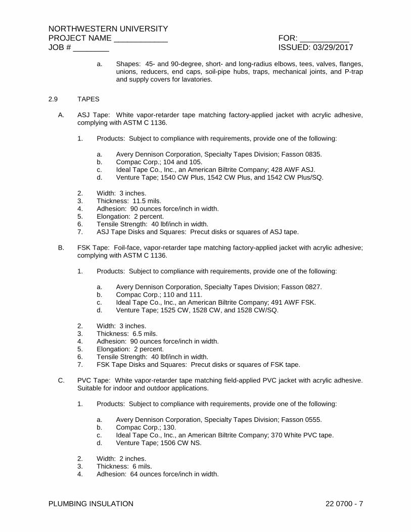
NORTHWESTERN UNIVERSITY PROJECT NAME ____________ FOR: ___________ JOB # ________ ISSUED: 03/29/2017
PLUMBING INSULATION 22 0700 - 7
a. Shapes: 45- and 90-degree, short- and long-radius elbows, tees, valves, flanges, unions, reducers, end caps, soil-pipe hubs, traps, mechanical joints, and P-trap and supply covers for lavatories.
2.9 TAPES
A. ASJ Tape: White vapor-retarder tape matching factory-applied jacket with acrylic adhesive, complying with ASTM C 1136.
1. Products: Subject to compliance with requirements, provide one of the following:
a. Avery Dennison Corporation, Specialty Tapes Division; Fasson 0835. b. Compac Corp.; 104 and 105. c. Ideal Tape Co., Inc., an American Biltrite Company; 428 AWF ASJ. d. Venture Tape; 1540 CW Plus, 1542 CW Plus, and 1542 CW Plus/SQ.
2. Width: 3 inches. 3. Thickness: 11.5 mils. 4. Adhesion: 90 ounces force/inch in width. 5. Elongation: 2 percent. 6. Tensile Strength: 40 lbf/inch in width. 7. ASJ Tape Disks and Squares: Precut disks or squares of ASJ tape.
B. FSK Tape: Foil-face, vapor-retarder tape matching factory-applied jacket with acrylic adhesive; complying with ASTM C 1136.
1. Products: Subject to compliance with requirements, provide one of the following:
a. Avery Dennison Corporation, Specialty Tapes Division; Fasson 0827. b. Compac Corp.; 110 and 111. c. Ideal Tape Co., Inc., an American Biltrite Company; 491 AWF FSK. d. Venture Tape; 1525 CW, 1528 CW, and 1528 CW/SQ.
2. Width: 3 inches. 3. Thickness: 6.5 mils. 4. Adhesion: 90 ounces force/inch in width. 5. Elongation: 2 percent. 6. Tensile Strength: 40 lbf/inch in width. 7. FSK Tape Disks and Squares: Precut disks or squares of FSK tape.
C. PVC Tape: White vapor-retarder tape matching field-applied PVC jacket with acrylic adhesive. Suitable for indoor and outdoor applications.
1. Products: Subject to compliance with requirements, provide one of the following:
a. Avery Dennison Corporation, Specialty Tapes Division; Fasson 0555. b. Compac Corp.; 130. c. Ideal Tape Co., Inc., an American Biltrite Company; 370 White PVC tape. d. Venture Tape; 1506 CW NS.
2. Width: 2 inches. 3. Thickness: 6 mils. 4. Adhesion: 64 ounces force/inch in width.
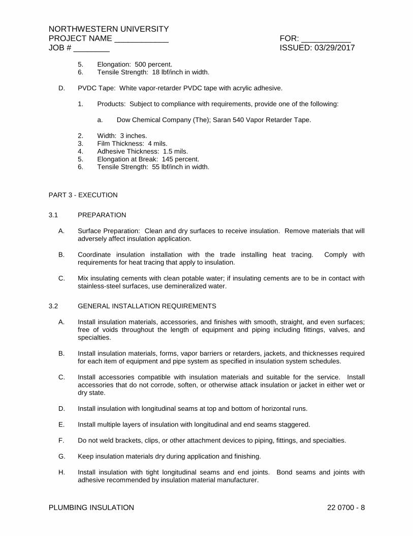
NORTHWESTERN UNIVERSITY PROJECT NAME ____________ FOR: ___________ JOB # ________ ISSUED: 03/29/2017
PLUMBING INSULATION 22 0700 - 8
5. Elongation: 500 percent. 6. Tensile Strength: 18 lbf/inch in width.
D. PVDC Tape: White vapor-retarder PVDC tape with acrylic adhesive.
1. Products: Subject to compliance with requirements, provide one of the following:
a. Dow Chemical Company (The); Saran 540 Vapor Retarder Tape.
2. Width: 3 inches. 3. Film Thickness: 4 mils. 4. Adhesive Thickness: 1.5 mils. 5. Elongation at Break: 145 percent. 6. Tensile Strength: 55 lbf/inch in width.
PART 3 - EXECUTION
3.1 PREPARATION
A. Surface Preparation: Clean and dry surfaces to receive insulation. Remove materials that will adversely affect insulation application.
B. Coordinate insulation installation with the trade installing heat tracing. Comply with requirements for heat tracing that apply to insulation.
C. Mix insulating cements with clean potable water; if insulating cements are to be in contact with stainless-steel surfaces, use demineralized water.
3.2 GENERAL INSTALLATION REQUIREMENTS
A. Install insulation materials, accessories, and finishes with smooth, straight, and even surfaces; free of voids throughout the length of equipment and piping including fittings, valves, and specialties.
B. Install insulation materials, forms, vapor barriers or retarders, jackets, and thicknesses required for each item of equipment and pipe system as specified in insulation system schedules.
C. Install accessories compatible with insulation materials and suitable for the service. Install accessories that do not corrode, soften, or otherwise attack insulation or jacket in either wet or dry state.
D. Install insulation with longitudinal seams at top and bottom of horizontal runs.
E. Install multiple layers of insulation with longitudinal and end seams staggered.
F. Do not weld brackets, clips, or other attachment devices to piping, fittings, and specialties.
G. Keep insulation materials dry during application and finishing.
H. Install insulation with tight longitudinal seams and end joints. Bond seams and joints with adhesive recommended by insulation material manufacturer.
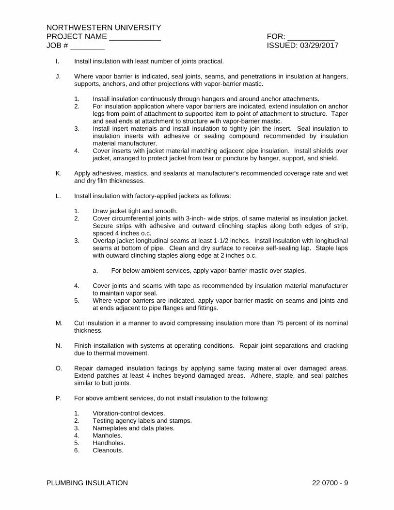
NORTHWESTERN UNIVERSITY PROJECT NAME ____________ FOR: ___________ JOB # ________ ISSUED: 03/29/2017
PLUMBING INSULATION 22 0700 - 9
I. Install insulation with least number of joints practical.
J. Where vapor barrier is indicated, seal joints, seams, and penetrations in insulation at hangers, supports, anchors, and other projections with vapor-barrier mastic.
1. Install insulation continuously through hangers and around anchor attachments. 2. For insulation application where vapor barriers are indicated, extend insulation on anchor
legs from point of attachment to supported item to point of attachment to structure. Taper and seal ends at attachment to structure with vapor-barrier mastic.
3. Install insert materials and install insulation to tightly join the insert. Seal insulation to insulation inserts with adhesive or sealing compound recommended by insulation material manufacturer.
4. Cover inserts with jacket material matching adjacent pipe insulation. Install shields over jacket, arranged to protect jacket from tear or puncture by hanger, support, and shield.
K. Apply adhesives, mastics, and sealants at manufacturer's recommended coverage rate and wet and dry film thicknesses.
L. Install insulation with factory-applied jackets as follows:
1. Draw jacket tight and smooth. 2. Cover circumferential joints with 3-inch- wide strips, of same material as insulation jacket.
Secure strips with adhesive and outward clinching staples along both edges of strip, spaced 4 inches o.c.
3. Overlap jacket longitudinal seams at least 1-1/2 inches. Install insulation with longitudinal seams at bottom of pipe. Clean and dry surface to receive self-sealing lap. Staple laps with outward clinching staples along edge at 2 inches o.c.
a. For below ambient services, apply vapor-barrier mastic over staples.
4. Cover joints and seams with tape as recommended by insulation material manufacturer to maintain vapor seal.
5. Where vapor barriers are indicated, apply vapor-barrier mastic on seams and joints and at ends adjacent to pipe flanges and fittings.
M. Cut insulation in a manner to avoid compressing insulation more than 75 percent of its nominal thickness.
N. Finish installation with systems at operating conditions. Repair joint separations and cracking due to thermal movement.
O. Repair damaged insulation facings by applying same facing material over damaged areas. Extend patches at least 4 inches beyond damaged areas. Adhere, staple, and seal patches similar to butt joints.
P. For above ambient services, do not install insulation to the following:
1. Vibration-control devices. 2. Testing agency labels and stamps. 3. Nameplates and data plates. 4. Manholes. 5. Handholes. 6. Cleanouts.

NORTHWESTERN UNIVERSITY PROJECT NAME ____________ FOR: ___________ JOB # ________ ISSUED: 03/29/2017
PLUMBING INSULATION 22 0700 - 10
3.3 PENETRATIONS
A. Insulation Installation at Roof Penetrations: Install insulation continuously through roof penetrations.
1. Seal penetrations with flashing sealant. 2. For applications requiring only indoor insulation, terminate insulation above roof surface
and seal with joint sealant. For applications requiring indoor and outdoor insulation, install insulation for outdoor applications tightly joined to indoor insulation ends. Seal joint with joint sealant.
3. Extend jacket of outdoor insulation outside roof flashing at least 2 inches below top of roof flashing.
4. Seal jacket to roof flashing with flashing sealant.
B. Insulation Installation at Underground Exterior Wall Penetrations: Terminate insulation flush with sleeve seal. Seal terminations with flashing sealant.
C. Insulation Installation at Aboveground Exterior Wall Penetrations: Install insulation continuously through wall penetrations.
1. Seal penetrations with flashing sealant. 2. For applications requiring only indoor insulation, terminate insulation inside wall surface
and seal with joint sealant. For applications requiring indoor and outdoor insulation, install insulation for outdoor applications tightly joined to indoor insulation ends. Seal joint with joint sealant.
3. Extend jacket of outdoor insulation outside wall flashing and overlap wall flashing at least 2 inches.
4. Seal jacket to wall flashing with flashing sealant.
D. Insulation Installation at Interior Wall and Partition Penetrations (That Are Not Fire Rated): Install insulation continuously through walls and partitions.
E. Insulation Installation at Fire-Rated Wall and Partition Penetrations: Install insulation continuously through penetrations of fire-rated walls and partitions.
1. Comply with requirements in Division 07 Section "Penetration Firestopping" and fire-resistive joint sealers.
F. Insulation Installation at Floor Penetrations:
1. Pipe: Install insulation continuously through floor penetrations. 2. Seal penetrations through fire-rated assemblies. Comply with requirements in
Division 07 Section "Penetration Firestopping."
3.4 GENERAL PIPE INSULATION INSTALLATION
A. Requirements in this article generally apply to all insulation materials except where more specific requirements are specified in various pipe insulation material installation articles.
B. Insulation Installation on Fittings, Valves, Strainers, Flanges, and Unions:
1. Install insulation over fittings, valves, strainers, flanges, unions, and other specialties with continuous thermal and vapor-retarder integrity, unless otherwise indicated.
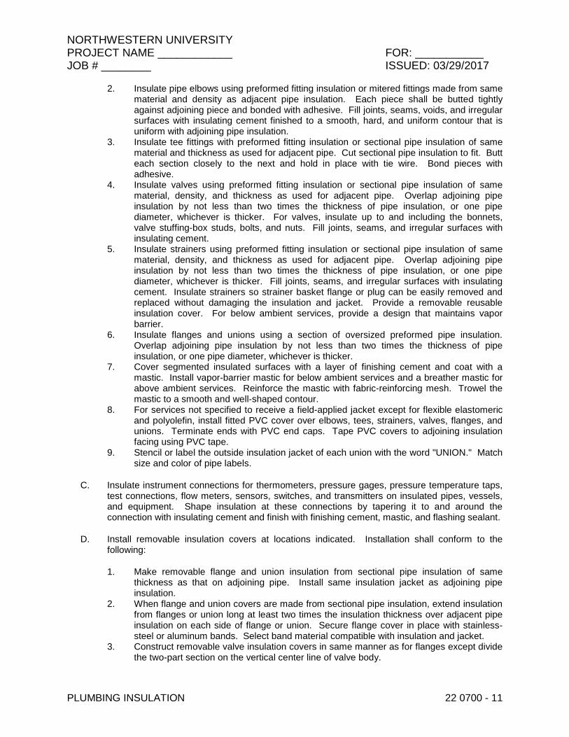
NORTHWESTERN UNIVERSITY PROJECT NAME ____________ FOR: ___________ JOB # ________ ISSUED: 03/29/2017
PLUMBING INSULATION 22 0700 - 11
2. Insulate pipe elbows using preformed fitting insulation or mitered fittings made from same material and density as adjacent pipe insulation. Each piece shall be butted tightly against adjoining piece and bonded with adhesive. Fill joints, seams, voids, and irregular surfaces with insulating cement finished to a smooth, hard, and uniform contour that is uniform with adjoining pipe insulation.
3. Insulate tee fittings with preformed fitting insulation or sectional pipe insulation of same material and thickness as used for adjacent pipe. Cut sectional pipe insulation to fit. Butt each section closely to the next and hold in place with tie wire. Bond pieces with adhesive.
4. Insulate valves using preformed fitting insulation or sectional pipe insulation of same material, density, and thickness as used for adjacent pipe. Overlap adjoining pipe insulation by not less than two times the thickness of pipe insulation, or one pipe diameter, whichever is thicker. For valves, insulate up to and including the bonnets, valve stuffing-box studs, bolts, and nuts. Fill joints, seams, and irregular surfaces with insulating cement.
5. Insulate strainers using preformed fitting insulation or sectional pipe insulation of same material, density, and thickness as used for adjacent pipe. Overlap adjoining pipe insulation by not less than two times the thickness of pipe insulation, or one pipe diameter, whichever is thicker. Fill joints, seams, and irregular surfaces with insulating cement. Insulate strainers so strainer basket flange or plug can be easily removed and replaced without damaging the insulation and jacket. Provide a removable reusable insulation cover. For below ambient services, provide a design that maintains vapor barrier.
6. Insulate flanges and unions using a section of oversized preformed pipe insulation. Overlap adjoining pipe insulation by not less than two times the thickness of pipe insulation, or one pipe diameter, whichever is thicker.
7. Cover segmented insulated surfaces with a layer of finishing cement and coat with a mastic. Install vapor-barrier mastic for below ambient services and a breather mastic for above ambient services. Reinforce the mastic with fabric-reinforcing mesh. Trowel the mastic to a smooth and well-shaped contour.
8. For services not specified to receive a field-applied jacket except for flexible elastomeric and polyolefin, install fitted PVC cover over elbows, tees, strainers, valves, flanges, and unions. Terminate ends with PVC end caps. Tape PVC covers to adjoining insulation facing using PVC tape.
9. Stencil or label the outside insulation jacket of each union with the word "UNION." Match size and color of pipe labels.
C. Insulate instrument connections for thermometers, pressure gages, pressure temperature taps, test connections, flow meters, sensors, switches, and transmitters on insulated pipes, vessels, and equipment. Shape insulation at these connections by tapering it to and around the connection with insulating cement and finish with finishing cement, mastic, and flashing sealant.
D. Install removable insulation covers at locations indicated. Installation shall conform to the following:
1. Make removable flange and union insulation from sectional pipe insulation of same thickness as that on adjoining pipe. Install same insulation jacket as adjoining pipe insulation.
2. When flange and union covers are made from sectional pipe insulation, extend insulation from flanges or union long at least two times the insulation thickness over adjacent pipe insulation on each side of flange or union. Secure flange cover in place with stainless-steel or aluminum bands. Select band material compatible with insulation and jacket.
3. Construct removable valve insulation covers in same manner as for flanges except divide the two-part section on the vertical center line of valve body.

NORTHWESTERN UNIVERSITY PROJECT NAME ____________ FOR: ___________ JOB # ________ ISSUED: 03/29/2017
PLUMBING INSULATION 22 0700 - 12
4. When covers are made from block insulation, make two halves, each consisting of mitered blocks wired to stainless-steel fabric. Secure this wire frame, with its attached insulation, to flanges with tie wire. Extend insulation at least 2 inches over adjacent pipe insulation on each side of valve. Fill space between flange or union cover and pipe insulation with insulating cement. Finish cover assembly with insulating cement applied in two coats. After first coat is dry, apply and trowel second coat to a smooth finish.
5. Unless a PVC jacket is indicated in field-applied jacket schedules, finish exposed surfaces with a metal jacket.
3.5 FLEXIBLE ELASTOMERIC INSULATION INSTALLATION
A. Seal longitudinal seams and end joints with manufacturer's recommended adhesive to eliminate openings in insulation that allow passage of air to surface being insulated.
B. Insulation Installation on Pipe Flanges:
1. Install pipe insulation to outer diameter of pipe flange. 2. Make width of insulation section same as overall width of flange and bolts, plus twice the
thickness of pipe insulation. 3. Fill voids between inner circumference of flange insulation and outer circumference of
adjacent straight pipe segments with cut sections of sheet insulation of same thickness as pipe insulation.
4. Secure insulation to flanges and seal seams with manufacturer's recommended adhesive to eliminate openings in insulation that allow passage of air to surface being insulated.
C. Insulation Installation on Pipe Fittings and Elbows:
1. Install mitered sections of pipe insulation. 2. Secure insulation materials and seal seams with manufacturer's recommended adhesive
to eliminate openings in insulation that allow passage of air to surface being insulated.
D. Insulation Installation on Valves and Pipe Specialties:
1. Install preformed valve covers manufactured of same material as pipe insulation when available.
2. When preformed valve covers are not available, install cut sections of pipe and sheet insulation to valve body. Arrange insulation to permit access to packing and to allow valve operation without disturbing insulation.
3. Install insulation to flanges as specified for flange insulation application. 4. Secure insulation to valves and specialties and seal seams with manufacturer's
recommended adhesive to eliminate openings in insulation that allow passage of air to surface being insulated.
3.6 MINERAL-FIBER INSULATION INSTALLATION
A. Insulation Installation on Straight Pipes and Tubes:
1. Secure each layer of preformed pipe insulation to pipe with wire or bands and tighten bands without deforming insulation materials.
2. Where vapor barriers are indicated, seal longitudinal seams, end joints, and protrusions with vapor-barrier mastic and joint sealant.
3. For insulation with factory-applied jackets on above ambient surfaces, secure laps with outward clinched staples at 6 inches o.c.

NORTHWESTERN UNIVERSITY PROJECT NAME ____________ FOR: ___________ JOB # ________ ISSUED: 03/29/2017
PLUMBING INSULATION 22 0700 - 13
4. For insulation with factory-applied jackets on below ambient surfaces, do not staple longitudinal tabs but secure tabs with additional adhesive as recommended by insulation material manufacturer and seal with vapor-barrier mastic and flashing sealant.
B. Insulation Installation on Pipe Flanges:
1. Install preformed pipe insulation to outer diameter of pipe flange. 2. Make width of insulation section same as overall width of flange and bolts, plus twice the
thickness of pipe insulation. 3. Fill voids between inner circumference of flange insulation and outer circumference of
adjacent straight pipe segments with mineral-fiber blanket insulation. 4. Install jacket material with manufacturer's recommended adhesive, overlap seams at
least 1 inch, and seal joints with flashing sealant.
C. Insulation Installation on Pipe Fittings and Elbows:
1. Install preformed sections of same material as straight segments of pipe insulation when available.
2. When preformed insulation elbows and fittings are not available, install mitered sections of pipe insulation, to a thickness equal to adjoining pipe insulation. Secure insulation materials with wire or bands.
D. Insulation Installation on Valves and Pipe Specialties:
1. Install preformed sections of same material as straight segments of pipe insulation when available.
2. When preformed sections are not available, install mitered sections of pipe insulation to valve body.
3. Arrange insulation to permit access to packing and to allow valve operation without disturbing insulation.
4. Install insulation to flanges as specified for flange insulation application.
3.7 POLYOLEFIN INSULATION INSTALLATION
A. Insulation Installation on Straight Pipes and Tubes:
1. Seal split-tube longitudinal seams and end joints with manufacturer's recommended adhesive to eliminate openings in insulation that allow passage of air to surface being insulated.
B. Insulation Installation on Pipe Flanges:
1. Install pipe insulation to outer diameter of pipe flange. 2. Make width of insulation section same as overall width of flange and bolts, plus twice the
thickness of pipe insulation. 3. Fill voids between inner circumference of flange insulation and outer circumference of
adjacent straight pipe segments with cut sections of polyolefin sheet insulation of same thickness as pipe insulation.
4. Secure insulation to flanges and seal seams with manufacturer's recommended adhesive to eliminate openings in insulation that allow passage of air to surface being insulated.
C. Insulation Installation on Pipe Fittings and Elbows:

NORTHWESTERN UNIVERSITY PROJECT NAME ____________ FOR: ___________ JOB # ________ ISSUED: 03/29/2017
PLUMBING INSULATION 22 0700 - 14
1. Install mitered sections of polyolefin pipe insulation. 2. Secure insulation materials and seal seams with manufacturer's recommended adhesive
to eliminate openings in insulation that allow passage of air to surface being insulated.
D. Insulation Installation on Valves and Pipe Specialties:
1. Install cut sections of polyolefin pipe and sheet insulation to valve body. 2. Arrange insulation to permit access to packing and to allow valve operation without
disturbing insulation. 3. Install insulation to flanges as specified for flange insulation application. 4. Secure insulation to valves and specialties, and seal seams with manufacturer's
recommended adhesive to eliminate openings in insulation that allow passage of air to surface being insulated.
3.8 FIELD-APPLIED JACKET INSTALLATION
A. Where FSK jackets are indicated, install as follows:
1. Draw jacket material smooth and tight. 2. Install lap or joint strips with same material as jacket. 3. Secure jacket to insulation with manufacturer's recommended adhesive. 4. Install jacket with 1-1/2-inch laps at longitudinal seams and 3-inch- wide joint strips at end
joints. 5. Seal openings, punctures, and breaks in vapor-retarder jackets and exposed insulation
with vapor-barrier mastic.
B. Where PVC jackets are indicated, install with 1-inch overlap at longitudinal seams and end joints; for horizontal applications, install with longitudinal seams along top and bottom of tanks and vessels. Seal with manufacturer's recommended adhesive.
1. Apply two continuous beads of adhesive to seams and joints, one bead under lap and the finish bead along seam and joint edge.
C. Where metal jackets are indicated, install with 2-inch overlap at longitudinal seams and end joints. Overlap longitudinal seams arranged to shed water. Seal end joints with weatherproof sealant recommended by insulation manufacturer. Secure jacket with stainless-steel bands 12 inches o.c. and at end joints.
D. Where PVDC jackets are indicated, install as follows:
1. Apply three separate wraps of filament tape per insulation section to secure pipe insulation to pipe prior to installation of PVDC jacket.
2. Wrap factory-presized jackets around individual pipe insulation sections with one end overlapping the previously installed sheet. Install presized jacket with an approximate overlap at butt joint of 2 inches over the previous section. Adhere lap seal using adhesive or SSL, and then apply 1-1/4 circumferences of appropriate PVDC tape around overlapped butt joint.
3. Continuous jacket can be spiral wrapped around a length of pipe insulation. Apply adhesive or PVDC tape at overlapped spiral edge. When electing to use adhesives, refer to manufacturer's written instructions for application of adhesives along this spiral edge to maintain a permanent bond.
4. Jacket can be wrapped in cigarette fashion along length of roll for insulation systems with an outer circumference of 33-1/2 inches or less. The 33-1/2-inch- circumference limit

NORTHWESTERN UNIVERSITY PROJECT NAME ____________ FOR: ___________ JOB # ________ ISSUED: 03/29/2017
PLUMBING INSULATION 22 0700 - 15
allows for 2-inch- overlap seal. Using the length of roll allows for longer sections of jacket to be installed at one time. Use adhesive on the lap seal. Visually inspect lap seal for "fishmouthing," and use PVDC tape along lap seal to secure joint.
5. Repair holes or tears in PVDC jacket by placing PVDC tape over the hole or tear and wrapping a minimum of 1-1/4 circumferences to avoid damage to tape edges.
3.9 FINISHES
A. Equipment and Pipe Insulation with ASJ or Other Paintable Jacket Material: Paint jacket with paint system identified below and as specified in Division 09 painting Sections.
1. Flat Acrylic Finish: Two finish coats over a primer that is compatible with jacket material and finish coat paint. Add fungicidal agent to render fabric mildew proof.
a. Finish Coat Material: Interior, flat, latex-emulsion size.
B. Flexible Elastomeric Thermal Insulation: After adhesive has fully cured, apply two coats of insulation manufacturer's recommended protective coating.
C. Color: Final color as selected by Architect. Vary first and second coats to allow visual inspection of the completed Work.
D. Do not field paint aluminum or stainless-steel jackets.
3.10 FIELD QUALITY CONTROL
A. Perform tests and inspections.
B. Tests and Inspections:
1. Inspect pipe, fittings, strainers, and valves, randomly selected by Architect, by removing field-applied jacket and insulation in layers in reverse order of their installation. Extent of inspection shall be limited to three locations of straight pipe, three locations of threaded fittings, three locations of welded fittings, two locations of threaded strainers, locations of welded strainers, locations of threaded valves, and locations of flanged valves for each pipe service defined in the "Piping Insulation Schedule, General" Article.
C. All insulation applications will be considered defective Work if sample inspection reveals noncompliance with requirements.
3.11 PIPING INSULATION SCHEDULE, GENERAL
A. Acceptable preformed pipe and tubular insulation materials and thicknesses are identified for each piping system and pipe size range. If more than one material is listed for a piping system, selection from materials listed is Contractor's option.
B. Items Not Insulated: Unless otherwise indicated, do not install insulation on the following:
1. Drainage piping located in crawl spaces. 2. Underground piping. 3. Chrome-plated pipes and fittings unless there is a potential for personnel injury.

NORTHWESTERN UNIVERSITY PROJECT NAME ____________ FOR: ___________ JOB # ________ ISSUED: 03/29/2017
PLUMBING INSULATION 22 0700 - 16
3.12 INDOOR PIPING INSULATION SCHEDULE
A. Domestic Cold and Non-potable Cold Water: Insulation shall be one of the following:
1. Flexible Elastomeric: 1/2 inch thick for pipe sizes less than 1-1/2 inches, 1 inch thick for pipe sizes 2 inches and greater
2. Mineral-Fiber, Preformed Pipe Insulation, Type I: 1/2 inch thick for pipe sizes less than 1-1/2 inches, 1 inch thick for pipe sizes 2 inches and greater
3. Polyolefin: 1/2 inch thick for pipe sizes less than 1-1/2 inches, 1 inch thick for pipe sizes 2 inches and greater
B. Domestic Hot, and Re-circulated Hot Water and Tempered Water: Insulation shall be one of the following:
1. Flexible Elastomeric: 1 inch thick. 2. Mineral-Fiber, Preformed Pipe Insulation, Type I: 1 inch thick. 3. Polyolefin: 1 inch thick.
C. Horizontal Stormwater and Emergency Drain: Insulation shall be one of the following:
1. Flexible Elastomeric: 1 inch thick. 2. Mineral-Fiber, Preformed Pipe Insulation, Type I: 1 inch thick. 3. Polyolefin: 1 inch thick.
D. Roof Drain and Emergency Drain Bodies: Insulation shall be one of the following:
1. Flexible Elastomeric: 1 inch thick. 2. Mineral-Fiber, Preformed Pipe Insulation, Type I: 1 inch Insert thickness thick. 3. Polyolefin: 1 inch thick.
E. Exposed Sanitary Drains, Domestic Water, Domestic Hot Water, and Stops at lavatories shall be insulated and finished with Truebro Model No. 102 "Lav-Guard" or Brocar "Trap-Wrap" white insulation kit.
F. Sanitary Waste Piping Where Heat Tracing Is Installed, insulation shall be:
1. Mineral-Fiber, Preformed Pipe Insulation, Type I: 1-1/2 inches thick.
3.13 OUTDOOR, ABOVEGROUND PIPING INSULATION SCHEDULE
A. Domestic Cold, Hot, and Recirculated Hot Water: Insulation shall be one of the following:
1. Flexible Elastomeric: 2 inches thick. 2. Mineral-Fiber, Preformed Pipe Insulation, Type I: 2 inches thick.
B. Sanitary Waste Piping Where Heat Tracing Is Installed: Insulation shall be:
1. Mineral-Fiber, Preformed Pipe Insulation, Type I: 2 inches thick.
3.14 OUTDOOR, FIELD-APPLIED JACKET SCHEDULE
A. Install jacket over insulation material. For insulation with factory-applied jacket, install the field-applied jacket over the factory-applied jacket.

NORTHWESTERN UNIVERSITY PROJECT NAME ____________ FOR: ___________ JOB # ________ ISSUED: 03/29/2017
PLUMBING INSULATION 22 0700 - 17
B. If more than one material is listed, selection from materials listed is Contractor's option.
C. Piping, Exposed:
1. PVC: 20 mils thick.
3.15 Aluminum, Smooth or Corrugated or Stucco Embossed: 0.016 inch thick.
END OF SECTION 22 0700

NORTHWESTERN UNIVERSITY PROJECT NAME ____________ FOR: ___________ JOB # ________ ISSUED: 03/29/2017
PLUMBING INSULATION 22 0700 - 18
THIS PAGE IS INTENTIONALLY BLANK

NORTHWESTERN UNIVERSITY PROJECT NAME ____________ FOR: ___________ JOB # ________ ISSUED: 03/29/2017
COMMISSIONING PLUMBING SYSTEMS 22 0800 - 1
SECTION 22 0800 - COMMISSIONING OF PLUMBING SYSTEMS
GENERAL
1.1 SUMMARY
The purpose of this section is to specify the Division 22 responsibilities and participation in the Commissioning Process.
Work under this contract shall conform to requirements of Division 01, General Requirements, Conditions of the Contract, and Supplementary Conditions. This specification covers commissioning of plumbing systems which are part of this project.
Commissioning work shall be a team effort to ensure that all plumbing equipment and systems have been completely and properly installed, function together correctly to meet the design intent, and document system performance. Commissioning shall coordinate system documentation, equipment start-up, control system calibration, testing and balancing, and verification and performance testing.
The Commissioning Team shall be made up of representatives from the Owner, Design Team, General Contractor (GC), manufacturers, and construction trades. The trades represented on the Commissioning Team shall include, but not be limited to: mechanical (including sheet metal and piping), Building Automation System, Test and Balance, Electrical, Plumbing and other specialty trades as necessary; fitting, controls, test and balance, and electrical. The lead person for each trade who will actually perform or supervise the work is to be designated as the representative to the Commissioning Team. Responsibility for various steps of the Commissioning Process shall be divided among the members of the Commissioning Team, as described in this section.
The Commissioning Authority (CxA) shall have responsibility for coordinating and directing each step of the Commissioning Process.
Plumbing system installation, start-up, testing, balancing, preparation of O&M manuals and operator training are the responsibility of the Division 22 Contractors, with coordination, observation, verification and commissioning the responsibility of the General Contractor per Division 01, Section 01 9113. The 01 9113 Commissioning Process does not relieve Division 22 – Contractor from the obligations to complete all portions of work in a satisfactory and fully operational manner.
Refer to Division 01, Section 01 9113, for a full list of commissioning related definitions. A few critical definitions are included below:
1. Commissioning. A systematic process that provides documented confirmation that specific and interconnected fire and life safety systems function according to the intended design criteria set forth in the project documents and satisfy the owner’s operational needs, including compliance requirements of any applicable laws, regulations, codes, and standards requiring fire and life safety systems.
2. Commissioning Authority (CxA). The qualified person, company, or agency that plans, coordinates, and oversees the entire Cx process.

NORTHWESTERN UNIVERSITY PROJECT NAME ____________ FOR: ___________ JOB # ________ ISSUED: 03/29/2017
COMMISSIONING PLUMBING SYSTEMS 22 0800 - 2
3. Commissioning Plan. The document prepared for each project, which identifies the processes and procedures necessary for a successful Cx process.
4. Commissioning Record. The complete set of commissioning documentation for the project, which is turned over to the owner at the end of the construction phase.
5. Functional Testing. Tests performed to verify compliance with manufacturers’ specifications, applicable codes and standards, and the project BOD and OPR.
1.2 RELATED SECTIONS
Division 01 Section 01 9113 - General Commissioning Requirements
Division 21 Section 21 0800 - Commissioning of Fire Suppression
Division 23 Section 23 0800 - Commissioning of HVAC Systems
Division 25 Section 25 0800 - Commissioning of Integrated Automation System
Division 26 Section 26 0800 - Commissioning of Electrical Systems
Individual Division 01, 21, 22, 23, 25, and 26 sections contain requirements related to the commissioning process.
1.3 ROLES AND RESPONSIBILITIES
Refer to Section 01 9113 for Commissioning Authority, Owner, Architect, and General Contractor roles and responsibilities.
Refer to Section 21 0800 for fire suppression contractor roles and responsibilities.
Refer to Section 22 0800 for plumbing contractor roles and responsibilities.
Refer to Section 23 0800 for Mechanical contractor roles and responsibilities.
Refer to Section 25 0800 for Integrated Automation System contractor roles and responsibilities.
Refer to Section 26 0800 for Electrical contractor roles and responsibilities.
Design Team
1. Provide the Owners Project Requirements (OPR). 2. Provide documentation of initial design concepts and Design Intent based on Owner’s
program. 3. Provide plumbing system design parameters and obtain approval of Owner. 4. Prepare contract documents incorporating Commissioning Specification requirements and
description of the electrical systems. 5. The Design Team shall specify and verify adequate maintenance accessibility for each
piece of equipment in shop drawings and the actual installation. 6. Periodic inspections as part of the Design Team’s contract with the Architect and/or Owner. 7. Review and approve submittals. 8. Participate in commissioning meetings. 9. Review Pre-functional Checklists and Functional Performance Test procedures submitted
by the Commissioning Authority. 10. Prepare punch lists.

NORTHWESTERN UNIVERSITY PROJECT NAME ____________ FOR: ___________ JOB # ________ ISSUED: 03/29/2017
COMMISSIONING PLUMBING SYSTEMS 22 0800 - 3
11. Review as-built records as required by contract documents. Issue a report noting deficiencies requiring correction to the Commissioning Authority.
12. Review and comment on final commissioning report.
Plumbing Contractor
1. Include cost to complete commissioning requirements for plumbing systems in the contract price.
2. Include requirements for submittal data, O&M data, and training in each purchase order or sub contract written.
3. Ensure cooperation and participation of all subcontractors. 4. Ensure participation of major equipment manufacturers in appropriate training and testing
activities. 5. Attend Construction Phase coordination meeting scheduled by the Commissioning
Authority. 6. Conduct plumbing system orientation and inspection when equipment is set. 7. Respond to (in writing) and address items documented in the Contractor Commissioning
Issues Log. 8. Notify the GC a minimum of two weeks in advance of system start-up and testing, so CxA
may be on site to witness. 9. Notify the GC a minimum of two weeks in advance, of the time for start of the TAB work.
Attend the initial TAB meeting for review of the TAB procedures. 10. Submit copies of all test results to the CxA. 11. Complete Pre-Functional Checklists for all equipment.
a. If no other system is agreed upon by Commissioning Team, Plumbing Contractor shall be responsible for completion of Pre-Functional Checklists for all equipment for which it issued a purchase order.
b. Plumbing Contractor shall coordinate completion of Pre-Functional Checklists with all other contractors that have made connections to equipment for which it issued a purchase order.
c. Remedy any deficiencies identified in Pre-Functional Checklists and notify CxA in writing that deficiencies have been addressed.
12. Assist the Commissioning Authority in all Pre-Functional Checklist verifications and Functional Performance Tests.
13. Prepare preliminary schedule for plumbing system orientation and inspections, O&M manual submission, training sessions, pipe system testing, flushing and cleaning, equipment start up, TAB, and task completion for use by the GC and Commissioning Authority. Update schedule as appropriate throughout the construction period.
14. Conduct plumbing system orientation and inspection when equipment is set in place. 15. Keep drawings updated as changes in the field are made, and review with the GC and
Commissioning Authority. 16. Gather O&M data on all equipment, and assemble in binders as required by the
Commissioning Specification. Submit to GC for review prior to the completion of construction.
17. Participate in, and schedule vendors and Contractors to participate in the training sessions as set up by the GC.
NORTHWESTERN UNIVERSITY PROJECT NAME ____________ FOR: ___________ JOB # ________ ISSUED: 03/29/2017
COMMISSIONING PLUMBING SYSTEMS 22 0800 - 4
18. Provide written notification to the General Contractor and Commissioning Authority that the following work has been completed in accordance with the contract documents, and that the equipment, systems, and sub-systems are functioning as required.
a. Domestic cold and hot water equipment and systems including all pumps, meters, backflow preventers, softeners, thermostatic mixing valves, and all Division 22 equipment.
b. Specialty plumbing systems, medical gas systems and certification, if applicable. c. Storm water system. d. Building automation systems are functioning to relay plumbing and medical gas
equipment alarms where required.
19. Submit training syllabus for approval to Commissioning Authority. 20. Participate in, and schedule vendors and Contractors to participate in the training sessions
as set up by the GC. Provide site-specific training information on digital media/electronic format (flash drive, CD, DVD). If training is videotaped, provide on digital media/electronic format (flash drive, CD, DVD).
21. Provide a complete set of as-built records to the GC. Hard Copy and Electronic Format (Flash Drive, CD, DVD, etc….) are required.
Test, Adjust, and Balance Contractor
1. Include cost for commissioning requirements in the contract price. 2. Attend initial commissioning coordination meeting scheduled by the Commissioning
Authority. 3. Submit the TAB procedures to the GC for review and acceptance. 4. Attend the TAB review meeting scheduled by the GC. Be prepared to discuss the
procedures that shall be followed in testing, adjusting and balancing the plumbing system. 5. Participate in training sessions as scheduled by the GC. 6. At the completion of the TAB work, and submittal of final TAB report, notify the Plumbing
Contractor. 7. Participate in verification of the TAB report, which will consist of repeating any selected
measurement contained in the TAB report where required by the Commissioning Authority for verification or diagnostic purposes.
Equipment Manufacturers and Miscellaneous Contractors
1. Include cost for commissioning requirements in the contract price. 2. Provide submittals, and appropriate O&M manual section(s). 3. Attend initial commissioning coordination meeting scheduled by the Commissioning
Authority. 4. Participate in training sessions as scheduled by the GC. 5. Demonstrate performance of equipment as applicable
1.4 SCOPE OF WORK
Commissioning work of Division 22 shall include, but not be limited to:
1. Testing and start-up of the equipment. 2. Logging in and checking the WCxS at least once a week for outstanding items. 3. Completion of Pre-Functional Checklists on the WCxS. 4. Testing, adjusting and balancing of domestic hot water systems. 5. Cooperation with the Commissioning Authority.

NORTHWESTERN UNIVERSITY PROJECT NAME ____________ FOR: ___________ JOB # ________ ISSUED: 03/29/2017
COMMISSIONING PLUMBING SYSTEMS 22 0800 - 5
6. Providing qualified personnel for participation in commissioning tests, including seasonal testing required after the initial testing.
7. Providing equipment, materials, and labor as necessary to correct construction and/or equipment deficiencies found during the Commissioning Process.
8. Providing operation and maintenance manuals and as-built drawings to the Commissioning Authority for verification.
9. Providing training and demonstrations for the systems specified in this Division.
The work included in the Commissioning Process involves a complete and thorough evaluation of the operation and performance of all components, systems, and sub-systems. The following equipment and systems shall be evaluated:
1. Low and high zone Domestic Water Heaters and associated recirculation pumps and mixing valves
2. Domestic Water Booster Pumps 3. Automatic Sprinkler System including the fire and jockey pumps 4. Sump Pumps and Elevator Pump 5. R/O or special water systems 6. Trap primers
System components which will not be functionally performance tested but will be included in the commissioning scope for conformance to the design documents, verification of specified Contractor testing, construction phase observation, and training verification shall include:
1. Medical Air Compressor, Vacuum Pump, and Manifolds 2. Medical Gas Outlets, Alarms, Zoning and Zone Valve Boxes (checking installation only,
not med gas certification)
Timely and accurate documentation is essential for the Commissioning Process to be effective. Documentation required as part of the Commissioning Process shall include but not be limited to:
1. Commissioning Process Reports, which may include the following:
a. Commissioning Field Reports b. Design Team Issues Log c. Contractor Commissioning Issues Log d. Meeting Minutes
2. Pre-start, and start-up procedures 3. Pre-Functional Checklists 4. Functional Performance Tests 5. Training agenda and materials 6. As-built records 7. Final commissioning report 8. Operation and maintenance (O&M) manuals
Detailed testing may be performed on all installed equipment and systems to ensure that operation and performance conform to contract documents. All tests shall be witnessed by the Commissioning Authority. The following testing is required as part of the Commissioning process:
1. Pre-Functional Checklists (PFC) are comprised of a full range of checks and tests to determine that all components, equipment, systems, and interfaces between systems operate in accordance with contract documents. Verification is completed by the Division 22, 23 and 26 contractors and documented using Pre-Functional Checklists.
NORTHWESTERN UNIVERSITY PROJECT NAME ____________ FOR: ___________ JOB # ________ ISSUED: 03/29/2017
COMMISSIONING PLUMBING SYSTEMS 22 0800 - 6
2. Functional Performance Tests (FPT) shall determine if the plumbing system is operating in accordance with the design intent. This includes all operating modes, interlocks, control responses, and specific responses to abnormal or emergency conditions.
Comprehensive training of O&M personnel shall be performed by the Plumbing Contractor, and where appropriate, by other sub-contractors, and vendors prior to turnover of building to the owner. The training shall include classroom instruction, along with hands-on instruction on the installed equipment and systems
1.5 DOCUMENTATION
The Commissioning Authority shall oversee and maintain the development of the document process. The GC shall facilitate project documentation through the web-based commissioning software. The commissioning documentation shall include, but not be limited to, the following:
1. Commissioning Plan 2. Commissioning Schedule 3. Document Request Log 4. Commissioning RFIs 5. Commissioning Field Reports on the WCxS 6. Design Team Issues Log on the WCxS 7. Contractor Commissioning Issues Log on the WCxS 8. Pre-Functional Checklists on the WCxS 9. Functional Performance Tests on the WCxS 10. See 01 9113 for additional information on the commissioning documentation.
PRODUCTS
2.1 TEST EQUIPMENT
The appropriate Contractor(s) shall furnish all special tools and equipment required for testing during the commissioning process. A list of all tools and equipment to be used during commissioning shall be submitted to the Commissioning Authority for approval. The owner shall furnish necessary utilities for the Commissioning Process.
2.2 TEST EQUIPMENT – PROPRIETARY
Proprietary test equipment and software required by any equipment manufacturer for programming and/or start-up, whether specified or not, shall be provided by the manufacturer of the equipment. Manufacturer shall provide the test equipment, demonstrate its use, and assist in the Commissioning Process as needed. Proprietary test equipment (and software) shall become the property of the owner upon completion of the Commissioning Process.

NORTHWESTERN UNIVERSITY PROJECT NAME ____________ FOR: ___________ JOB # ________ ISSUED: 03/29/2017
COMMISSIONING PLUMBING SYSTEMS 22 0800 - 7
EXECUTION
3.1 GENERAL
A pre-construction meeting of all Commissioning Team members shall be held at a time and place designated by the owner. The purpose shall be to familiarize all parties with the Commissioning Process, and to ensure that the responsibilities of each party are clearly understood.
The Contractor shall complete all phases of work so the systems can be started, tested, balanced, and commissioning procedures undertaken. This includes the complete installation of all equipment, materials, pipe, duct, wire, insulation, controls, etc., per the contract documents and related directives, clarifications, and change orders.
A Commissioning Plan shall be developed by the Commissioning Authority. The Contractor shall assist the Commissioning Authority in preparing the Commissioning Plan by providing all necessary information pertaining to the actual equipment and installation. If contractor-initiated system changes have been made that alter the Commissioning Process, the Commissioning Authority shall notify the Owner.
Acceptance procedures are normally intended to begin prior to completion of a system and/or sub-systems, and shall be coordinated with the Division 22 contractor. Start of acceptance procedures before system completion does not relieve the contractor from completing those systems as per the schedule.
3.2 PARTICIPATION IN COMMISSIONING
The Contractor shall provide skilled technicians to start-up and debug all systems within Division 22. These same technicians shall be made available to assist the Commissioning Authority in completing the commissioning program. Work schedules, time required for testing, etc., shall be requested by the Commissioning Authority and coordinated by the contractor. Contractor shall ensure that the qualified technician(s) are available and present during the agreed upon schedules and of sufficient duration to complete the necessary tests, adjustments, and/or problem resolutions.
System performance problems and discrepancies may require additional technician time, Commissioning Authority time, reconstruction of systems, and/or replacement of system components. The additional technician time shall be made available for subsequent commissioning periods until the required system performance is obtained.
The Commissioning Authority reserves the right to question the appropriateness and qualifications of the technicians relative to each item of equipment, system, and/or sub-system. Qualifications of technicians shall include expert knowledge relative to the specific equipment involved and a willingness to work with the Commissioning Authority. Contractor shall provide adequate documentation and tools to start up and test the equipment, system, and/or sub-system.
3.3 DEFICIENCY RESOLUTION
In some systems, maladjustments, misapplied equipment, and/or deficient performance under varying loads will result in additional work being required to commission the systems. This work shall be completed under the direction of the Owner, with input from the contractor, equipment manufacturer, and Commissioning Authority. Whereas all members shall have input and the

NORTHWESTERN UNIVERSITY PROJECT NAME ____________ FOR: ___________ JOB # ________ ISSUED: 03/29/2017
COMMISSIONING PLUMBING SYSTEMS 22 0800 - 8
opportunity to discuss, debate, and work out problems, the Owner shall make final determination over any additional required work to achieve performance.
Corrective work shall be completed in a timely fashion to permit the completion of the Commissioning Process. Experimentation to demonstrate system performance may be permitted. If the Commissioning Authority deems the experimentation work to be ineffective or untimely as it relates to the Commissioning Process, the Commissioning Authority shall notify the Owner, indicating the nature of the problem, expected steps to be taken, and suggested deadline(s) for completion of activities. If the deadline(s) pass without resolution of the problem, the Owner reserves the right to obtain supplementary services and/or equipment to resolve the problem. Costs incurred to solve the problems in an expeditious manner shall be the contractor’s responsibility.
The Owner’s contract with the Commissioning Authority includes up to two Functional Performance Tests of each piece of equipment or system included in the commissioning scope. Commissioning Authority time and expenses required for retests beyond two, if required, due to incomplete installation or otherwise, will be paid by the Owner and reimbursed by the contractor.
3.4 ADDITIONAL COMMISSIONING
Additional commissioning activities may be required after system adjustments, replacements, etc., are completed. The contractor(s), manufacturers, and Commissioning Authority shall include a reasonable reserve to complete this work as part of their contractual obligations.
3.5 CONSTRUCTION PHASE OBSERVATION
Scope of Construction Phase Observation
1. The Commissioning Authority will conduct periodic observations during the Construction Phase to monitor progress and compliance with the design intent and contract documents. It is the responsibility of the contractor to address the issues noted on the web-based commissioning application and notify Commissioning Authority of completion.
2. Commissioning Authority observations will coincide with Design Team observations and are not intended to take the place of this work.
Documentation and Reporting
1. Issues identified by the Commissioning Authority during Construction Phase will be documented using the web-based commissioning application and distributed to Commissioning Team members.
2. Progress during the Construction Phase will also be documented by the Commissioning Authority using Commissioning Process Reports.

NORTHWESTERN UNIVERSITY PROJECT NAME ____________ FOR: ___________ JOB # ________ ISSUED: 03/29/2017
COMMISSIONING PLUMBING SYSTEMS 22 0800 - 9
3.6 ACCEPTANCE PROCEDURES
Pre-Functional Checklists
1. Pre-Functional Checklist Scope
a. Tests and verifications included in the Pre-Functional Checklists shall determine if all components, equipment, systems, and interfaces between systems are installed and are ready to operate in accordance with contract documents.
2. Pre-Functional Checklist Roles and Responsibilities
a. The Commissioning Authority shall be responsible for creating the Checklists, which will be completed by the installing contractors and then verified (via spot checking and Functional Performance Testing). Participating contractors, manufacturers, etc. shall include all costs to do the work involved in these tests in their proposals. The following is a list of tasks and supporting information that shall be required:
b. The Plumbing Contractor shall provide the services of a technician(s) who is (are) familiar with the construction and operation of the applicable system. Provide access to the contract plans, shop drawings, and equipment cut sheets of all installed equipment.
3. Documentation and Reporting Requirements
a. Pre-Functional Checklists shall be provided for each component, piece of equipment, system, and sub-system, including all interfaces, interlocks, etc. Each item to be tested shall have a different entry line with space provided for comments. The checklists will include spaces for each party to sign off on.
b. Completed checklists shall be submitted to the Commissioning Authority for acceptance and inclusion in the commissioning report.
4. Acceptance of Pre-Functional Checklists
a. The Commissioning Authority will select, at random, 10 percent of the checklists for verification.
b. If 10 percent or more of the checklists are found to be inaccurate for each system or equipment type, all of the checklists for that system or equipment type will be rejected. Complete, accurate checklists will need to be resubmitted.
Test, Adjust, and Balance Verification
1. The Commissioning Authority shall select, at random, 10 percent of the report data for verification.
2. The TAB contractor shall be given sufficient advance notice of the date of field verification. However, they shall not be informed in advance of the data points to be verified.
NORTHWESTERN UNIVERSITY PROJECT NAME ____________ FOR: ___________ JOB # ________ ISSUED: 03/29/2017
COMMISSIONING PLUMBING SYSTEMS 22 0800 - 10
3. Failure of an item is defined as:
a. For all readings other than sound, a deviation of more than 10 percent. b. For sound pressure readings, a deviation of 3 decibels. (Note: variations in
background noise must be considered).
4. A failure of more than 10 percent of the selected items shall result in the rejection of the final TAB report.
Functional Performance Testing
1. Scope of Functional Performance Testing
a. Functional Performance Tests shall determine if equipment, system, and/or sub-system is operating in accordance with the final design intent. This includes all operating modes, interlocks, control responses, and specific responses to abnormal or emergency conditions. The following is a list of test examples:
1) Determine capability of the sewage ejector to evacuate sewage at the required rate of flow.
2) Determine capacity of domestic hot water system to deliver hot water at the design temperature.
3) Determine the ability of the sump pumps to detect and properly react to all required alarms.
2. Functional Performance Test Report
a. Detailed procedures for each series of tests will be developed by the Commissioning Authority for review and acceptance by the GC and Owner. The procedures shall include samples of the data sheets that will be part of the reports.
3. Participants in Functional Performance Tests
a. Participants in the Functional Performance Tests shall be the same as those listed in the Pre-Functional Checklists.
4. Functional Performance Test Procedures
a. The Commissioning Authority shall supervise and direct all Functional Performance Tests.
1) Set the system equipment (i.e. water heater, pumps, ejectors, etc.) into the operating mode to be tested (i.e. normal shut-down, normal auto position, normal manual position, unoccupied cycle, emergency power, and alarm conditions).
2) The Commissioning Authority shall inspect and verify the position of each device and interlock identified in the test procedure. Each item shall be signed off as acceptable (yes) or failed (no).
3) This test shall be repeated for each operating cycle that applies to the plumbing system being tested.
4) Operating checks shall include all safety cutouts, alarms, and interlocks with smoke control and life safety systems during all modes of operation of the plumbing system.
NORTHWESTERN UNIVERSITY PROJECT NAME ____________ FOR: ___________ JOB # ________ ISSUED: 03/29/2017
COMMISSIONING PLUMBING SYSTEMS 22 0800 - 11
5) If during a test an operating deficiency is observed, appropriate comments will be added to the Test Procedure form and the Issues Log.
6) Confirmation of the TAB results shall be verified utilizing the Building Automation System. This shall include, but not be limited to, the following:
a) Verify domestic hot water recirculation balancing.
7) Verification of the proper responses of BAS system controllers and sensors shall be as follows:
a) For each controller or sensor, record the indicated BAS system reading, and the test instrument reading.
b) If the initial test indicates that the test reading is outside of the control range of the installed device, the calibration of the installed device shall be checked and adjusted as required. The deficient device shall be re-tested and the results recorded on the Functional Performance Test form.
b. If deficiencies are identified during Functional Performance Testing, the General Contractor will be notified, and action taken to remedy the deficiency. The final Functional Test Procedure forms will be reviewed by the Commissioning Authority to determine if testing is complete and the system is functioning in accordance with the contract documents.
5. Documentation and Reporting Requirements
a. All measured data, data sheets, and a comprehensive summary, describing the operation of the plumbing system at the time of testing shall be submitted to the Commissioning Authority.
b. Data sheets used in verification of the proper operation of the control system shall include each controller to be verified, the system it serves, the service it provides, and its location. For each controller, provide space for recording the readout of the controller, the reading at the controller’s sensor(s), and any comments.
c. A preliminary Functional Performance Test report shall be prepared by the Commissioning Authority and submitted to the Design Team for review. Any identified deficiencies need to be evaluated by the Design Team and General Contractor to determine if they are part of the contractor’s or sub-contractor’s contractual obligations. Construction deficiencies shall be corrected by the responsible contractor(s), and the specific Functional Performance Test repeated.
d. f it is determined that the plumbing system is constructed in accordance with the contract documents, and the performance deficiencies are not part of the contract documents, the Owner must decide whether any required modifications needed to bring the performance of the plumbing system up to the finalized design intent shall be implemented, or if the test shall be accepted as submitted. If corrective work is performed, the owner shall determine if a portion or all required Functional Performance Tests should be repeated, and a revised report submitted.
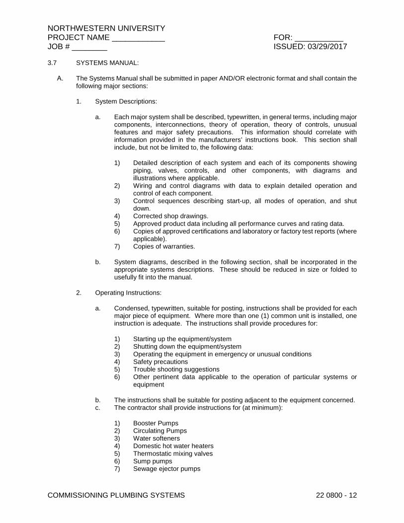
NORTHWESTERN UNIVERSITY PROJECT NAME ____________ FOR: ___________ JOB # ________ ISSUED: 03/29/2017
COMMISSIONING PLUMBING SYSTEMS 22 0800 - 12
3.7 SYSTEMS MANUAL:
The Systems Manual shall be submitted in paper AND/OR electronic format and shall contain the following major sections:
1. System Descriptions:
a. Each major system shall be described, typewritten, in general terms, including major components, interconnections, theory of operation, theory of controls, unusual features and major safety precautions. This information should correlate with information provided in the manufacturers’ instructions book. This section shall include, but not be limited to, the following data:
1) Detailed description of each system and each of its components showing piping, valves, controls, and other components, with diagrams and illustrations where applicable.
2) Wiring and control diagrams with data to explain detailed operation and control of each component.
3) Control sequences describing start-up, all modes of operation, and shut down.
4) Corrected shop drawings. 5) Approved product data including all performance curves and rating data. 6) Copies of approved certifications and laboratory or factory test reports (where
applicable). 7) Copies of warranties.
b. System diagrams, described in the following section, shall be incorporated in the appropriate systems descriptions. These should be reduced in size or folded to usefully fit into the manual.
2. Operating Instructions:
a. Condensed, typewritten, suitable for posting, instructions shall be provided for each major piece of equipment. Where more than one (1) common unit is installed, one instruction is adequate. The instructions shall provide procedures for:
1) Starting up the equipment/system 2) Shutting down the equipment/system 3) Operating the equipment in emergency or unusual conditions 4) Safety precautions 5) Trouble shooting suggestions 6) Other pertinent data applicable to the operation of particular systems or
equipment
b. The instructions shall be suitable for posting adjacent to the equipment concerned. c. The contractor shall provide instructions for (at minimum):
1) Booster Pumps 2) Circulating Pumps 3) Water softeners 4) Domestic hot water heaters 5) Thermostatic mixing valves 6) Sump pumps 7) Sewage ejector pumps

NORTHWESTERN UNIVERSITY PROJECT NAME ____________ FOR: ___________ JOB # ________ ISSUED: 03/29/2017
COMMISSIONING PLUMBING SYSTEMS 22 0800 - 13
3. Ongoing and Preventive Maintenance:
a. Condensed, typewritten procedures for recommended ongoing and preventive maintenance actions shall be provided for each category of equipment/system listed above. This information shall include, but not be limited to the following:
1) Maintenance and overhaul instructions. 2) Lubricating schedule including type, grade, temperature, and frequency
range. 3) Parts list, including source of supply and recommended spare parts. 4) Name, address, and 24 hour telephone number of each subcontractor who
installed equipment and systems, and local representative for each type of system.
5) Other pertinent data applicable to the maintenance of particular systems or equipment.
b. These recommended preventive maintenance actions shall be categorized by the following recommended frequencies:
1) Weekly 2) Monthly 3) Quarterly 4) Semi Annual 5) Annual 6) Other
Posted Operating Instructions and Diagrams:
1. Operating Instructions:
a. Copies of operating instructions provided in the Systems Manual shall be posted in the near vicinity of each piece of applicable equipment. The instructions shall be mounted neatly in frames under Plexiglas, where they can be easily read by operating personnel. Instructions mounted outdoors shall be suitably protected from weather.
3.8 SYSTEMS TRAINING:
The Plumbing Contractor, and appropriate sub-contractors, shall provide comprehensive systems instruction on building systems prior to delivery. The instruction shall include classroom instruction delivered by competent instructors based upon the contents of the Systems Manual. Emphasis shall be placed upon overall systems diagrams and descriptions, and how system components interact. The classroom instruction shall also include detailed equipment instruction by qualified manufacturer’s representatives for which operating instructions are provided. The manufacturer’s representative training shall emphasize operating instructions and preventive maintenance as described in the Systems Manual. At a minimum, the training sessions shall cover the following items:
1. Types of installed systems 2. Theory of operation
a. Design intent b. Emergency conditions and procedures
NORTHWESTERN UNIVERSITY PROJECT NAME ____________ FOR: ___________ JOB # ________ ISSUED: 03/29/2017
COMMISSIONING PLUMBING SYSTEMS 22 0800 - 14
c. Comfort conditions d. Energy efficiency e. Other issues important to facility operation
3. System operations 4. Use of control system
a. Sequence of operation b. Problem indicators c. Diagnostics d. Corrective actions
5. Service, maintenance, diagnostics and repair 6. Use of reports and logs 7. Troubleshooting, investigation of malfunctions, and determining reasons for the problem
Each classroom training period shall be followed by an inspection, explanation, and demonstration of the system by the instructors. The applicable equipment shall be demonstrated including system startup and shutdown, with the exception of sprinkler systems.
The contractor shall be responsible for organizing, arranging, and delivering this instruction in an efficient and effective manner on a schedule agreeable to the Owner.
The contractor shall provide, at or before substantial completion, a proposed agenda and schedule of the above training for approval by the Commissioning Authority and the Owner
END OF SECTION 22 0800
NORTHWESTERN UNIVERSITY PROJECT NAME ____________ FOR: ___________ JOB # ________ ISSUED: 03/29/2017
PLUMBING EQUIPMENT 22 1000 - 1
SECTION 22 1000 – PLUMBING EQUIPMENT
PART 1 - GENERAL
1.1 SUMMARY
A. Section Includes:
1. Self-Priming Sewage and Sump Pumps - With Four Solid State Level Switches. 2. Self-Priming Sewage and Sump Pumps - With Dual Level Switches. 3. Domestic Water Booster Pump Systems - High Pressure (Above 100 psi). 4. Domestic Water Booster Pump Systems - Low Pressure (100 psi maximum). 5. Electric Water Coolers. 6. Duplex Sump Pumps Systems - Duplex - Submersible Vortex or Semi-Open - 2 Digital
Level Switches. 7. Duplex Sump Pumps Systems - Submersible Vortex - 2 Digital Level Switches.
B. Related Sections:
1. Section 22 1118 “Domestic Water Distribution System.”
1.2 ACTION SUBMITTALS
A. Product Data: For each type of product indicated, including dimensions, rough-in and connection requirements, and electrical data.
1.3 CLOSEOUT SUBMITTALS
A. Operation and maintenance data.
B. Northwestern University Maintenance Requirement Forms, see division 01 for more information.
1.4 QUALITY ASSURANCE
A. Electrical Components, Devices, and Accessories: Listed and labeled as defined in NFPA 70, by a qualified testing agency, and marked for intended location and application.
B. UL Compliance: Comply with UL 778 for motor-operated water pumps.
C. Comply with requirements of NSF-61 and 372 as applicable to each type of pump system.
1.5 REFERENCE STANDARDS
A. The work in this section is subject to the requirements of applicable portions of the following standards:
1. HI - Hydraulic Institute
NORTHWESTERN UNIVERSITY PROJECT NAME ____________ FOR: ___________ JOB # ________ ISSUED: 03/29/2017
PLUMBING EQUIPMENT 22 1000 - 2
2. ANSI – American National Standards Institute 3. ASTM – American Society for Testing and Materials 4. IEEE – Institute of Electrical and Electronics Engineers 5. NEMA – National Electrical Manufacturers Association 6. NEC – National Electrical Code 7. UL – Underwriters Laboratories, Inc. 8. NSF - National Sanitation Foundation
PART 2 - PRODUCTS
2.1 SEWAGE EJECTOR AND SUMP PUMP SYSTEMS – DUPLEX – SELF-PRIMING - WITH FOUR SOLID STATE LEVEL SWITCHES
A. Provide self-priming sewage or sump pump systems, with four (4) digital level switches, of the sizes and capacities as noted on the drawings.
B. The pumps shall be duplex, self priming type designed for floor-level installation above the wet-well. The pumps shall be designed to facilitate pump maintenance and volute-cleaning above the wet-well, in a clean, dry and safe environment. Pump designs which require personnel to enter the confined-space of the wet-well for any reason, or lift equipment weighing many hundreds of pounds out of the wet-well for servicing, are not acceptable.
C. The pumping systems shall be as manufactured by Metropolitan Industries, of Romeoville, IL., and shall include two self priming sump pumps with close-coupled motors, mounted on an epoxy-coated steel basin cover provided with suction pipe openings, inspection-opening and suspension devices for the level controls.
D. The system shall be designed such that no equipment is installed below the basin-cover, other than the suction-pipes, vent-pipe, and four (4) solid-state level switches with stainless-steel mounting-chain & anchor, all of which shall be suspended from the cover.
E. Pump construction and design.
1. The pumps shall be capable of passing solids of the sizes indicated on the contract drawings. The impeller and removable volute lip-plate shall be constructed of ductile-iron. The complete pump rotating unit which includes the motor, motor mounting bracket, mechanical seal, replaceable volute-lip and impeller shall be removable as a one-piece unit, back-pull-out design, without disturbing the suction or discharge piping.
2. The impeller shall be of the enclosed type, with pump out vanes on both the front and the back shroud. The pump units shall include bronze case wear rings, and removable casing access covers, so that all parts of the pump suction-case, including the impeller port, shall be accessible for cleaning and inspection.
3. The pump casing shall be designed so that sufficient liquid is retained in the casing to re-prime the pump. The pump shall include an integral removable suction flap-valve, and shall be capable of re-prime, even if solids become lodged under suction flap-valve, causing liquid to drain back to the wet-well when the pump is idle.
4. The pump shall be provided with a vacuum-rated grooved-coupling, attached to the suction-elbow, for connection to the grooved-end suction pipe.
F. Close-coupled motor.
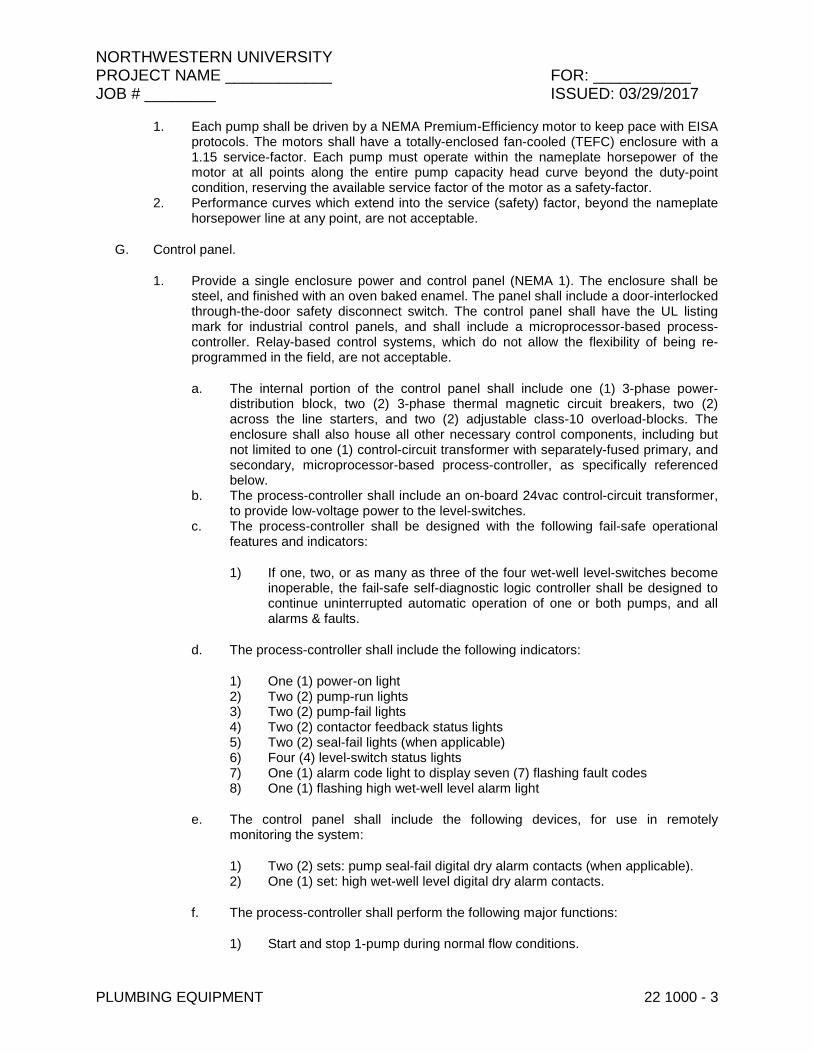
NORTHWESTERN UNIVERSITY PROJECT NAME ____________ FOR: ___________ JOB # ________ ISSUED: 03/29/2017
PLUMBING EQUIPMENT 22 1000 - 3
1. Each pump shall be driven by a NEMA Premium-Efficiency motor to keep pace with EISA protocols. The motors shall have a totally-enclosed fan-cooled (TEFC) enclosure with a 1.15 service-factor. Each pump must operate within the nameplate horsepower of the motor at all points along the entire pump capacity head curve beyond the duty-point condition, reserving the available service factor of the motor as a safety-factor.
2. Performance curves which extend into the service (safety) factor, beyond the nameplate horsepower line at any point, are not acceptable.
G. Control panel.
1. Provide a single enclosure power and control panel (NEMA 1). The enclosure shall be steel, and finished with an oven baked enamel. The panel shall include a door-interlocked through-the-door safety disconnect switch. The control panel shall have the UL listing mark for industrial control panels, and shall include a microprocessor-based process-controller. Relay-based control systems, which do not allow the flexibility of being re-programmed in the field, are not acceptable.
a. The internal portion of the control panel shall include one (1) 3-phase power-distribution block, two (2) 3-phase thermal magnetic circuit breakers, two (2) across the line starters, and two (2) adjustable class-10 overload-blocks. The enclosure shall also house all other necessary control components, including but not limited to one (1) control-circuit transformer with separately-fused primary, and secondary, microprocessor-based process-controller, as specifically referenced below.
b. The process-controller shall include an on-board 24vac control-circuit transformer, to provide low-voltage power to the level-switches.
c. The process-controller shall be designed with the following fail-safe operational features and indicators:
1) If one, two, or as many as three of the four wet-well level-switches become inoperable, the fail-safe self-diagnostic logic controller shall be designed to continue uninterrupted automatic operation of one or both pumps, and all alarms & faults.
d. The process-controller shall include the following indicators:
1) One (1) power-on light 2) Two (2) pump-run lights 3) Two (2) pump-fail lights 4) Two (2) contactor feedback status lights 5) Two (2) seal-fail lights (when applicable) 6) Four (4) level-switch status lights 7) One (1) alarm code light to display seven (7) flashing fault codes 8) One (1) flashing high wet-well level alarm light
e. The control panel shall include the following devices, for use in remotely monitoring the system:
1) Two (2) sets: pump seal-fail digital dry alarm contacts (when applicable). 2) One (1) set: high wet-well level digital dry alarm contacts.
f. The process-controller shall perform the following major functions:
1) Start and stop 1-pump during normal flow conditions.

NORTHWESTERN UNIVERSITY PROJECT NAME ____________ FOR: ___________ JOB # ________ ISSUED: 03/29/2017
PLUMBING EQUIPMENT 22 1000 - 4
2) Start and stop 2-pumps during extreme flow conditions. 3) Alternate two pumps on successive cycles of operation. 4) Monitor & delay pump-starts to avoid short-cycling motors. 5) Monitor & delay pump-starts to avoid simultaneous starting of pumps
following utility power losses. 6) Monitor & recognize inoperable level-switches, and modify system operation
to compensate for this occurrence. 7) Provide easily identifiable alarm codes for the operating personnel to
monitor. 8) Include separate fuses for each contactor circuit, as well as each alarm
circuit. 9) Monitor embedded pump-motor thermal-sensors, when wired.
2. The control system shall be provided with a Metropolitan “Metro-Mail”, messaging system, designed to monitor and report the status of the equipment to key personnel, during regular and/or emergency situations. The unit shall be capable of sending e-mail messages or text messages through an internet connection. The equipment control system shall include singular or multiple remote alarm contacts as designated within the equipment control system specifications. These shall be factory pre-wired to the Metro-Mail messaging system, each powered by a 10-to-30 volt ac-or-dc power supply. The messaging system shall include eight (8) electrically-separated, optically-isolated digital inputs. Each pair of input terminals shall include a red led-indicator light, which shall illuminate when the circuit is energized. The messaging system shall also include a single led-indicator status-light. This light shall glow-green to indicate that the unit is powered and is properly configured; and shall flash to indicate that an e-mail is being transmitted. The led-indicator shall glow-amber to indicate that the unit is booting, or to indicate that an ip-number has not been assigned. An ethernet port shall be provided, to allow connection of the unit to an internet connection, using a standard or crossover ethernet cable. The Metro-Mail shall include an on-board web-server, allowing the user to configure messages; e-mail addresses; and other settings, via a standard web browser. The Metro-Mail shall be powered through the main equipment control system, via a 10-to-30 vac/dc power supply.
3. Control systems without all of the essential fail-safe operational features, lights, fault-codes, indicators, and remote-monitoring devices listed above are insufficient for the intended service, and are not acceptable.
4. Provide BAS options on panel or extra connection points for future BAS connection. Confirm requirements with NU.
H. Liquid level sensors.
1. Provide four (4) suspended solid-state digital level-switches, of the strain-gauge type, designed with no moving parts. Mechanically operated switches, which are more susceptible to failure, are not acceptable. Cord grips fastened to the basin-cover shall be used to support the level-switch cords. The switches shall be fastened to a stainless-steel chain with anchor, in such a way that allows level-adjustment of the switches from above the basin cover. These level-switches shall be used to control & monitor liquid level in the wet-well.
2. The switch installed in the lowest position shall shut off all pumps. The next switch from the bottom will start one pump and shall trigger alternation of the pumps on each successive cycle of operation. The third switch from the bottom shall start both pumps or start the second pump if the first pump fails for any reason.
3. The fourth switch shall be located at the highest point, at the invert of the basin inlet, and shall signal a high wet-well level alarm. All level-switches shall be removable through the basin cover.

NORTHWESTERN UNIVERSITY PROJECT NAME ____________ FOR: ___________ JOB # ________ ISSUED: 03/29/2017
PLUMBING EQUIPMENT 22 1000 - 5
I. Field installation requirements.
1. A suction pipe shall be provided by the contractor and installed on each pump. The suction pipe must be of 1-piece construction, and shall be schedule-80 PVC, galvanized steel, or iron pipe. The size of the pipe shall be the same size as the pump suction connection. The suction pipes shall be installed air tight. The bottom end of the pipe shall be installed to a point measuring 6"-to-8” from the wet well floor.
2. An appropriate sewage-type check-valve shall be provided by the contractor and shall be installed in the discharge line of each pump. An appropriate gate-valve or plug-valve shall be provided by the contractor and shall be installed downstream of the check-valve.
3. A small diameter air vent line & isolation-valve shall be provided by the contractor & installed on each pump, per the manufacturer’s instructions. It shall be designed to evacuate any air on the discharge side of the pump-impeller, between the pump discharge nozzle and the discharge check valve. The outlet of the air vent line shall discharge into the wet well through the basin-cover. The line shall extend from the basin-cover, down into the wet-well, and must terminate below the liquid-level, but no lower than a point 6”-to-8” above the bottom of the suction pipe.
J. Qualification Of Equipment Manufacturer:
1. In order to establish a standard of quality and to insure a uniform basis of bidding, the system shall be manufactured by Metropolitan Industries, Inc., or a prior written approval equal, approved by FMDC and FMO plumbing staff. To be considered an approved equal, complete details and shop drawings must be submitted to the engineer no later than ten (10) days prior to the bid date. Sufficient data must be submitted so that the engineer has the required information available to determine whether the alternate system meets the requirements of the specifications. The contractor shall prepare his bid on the basis of the specific system specified for purposed of determining the low bid. After the execution of the contract, substitution of non-specified equipment will be considered, if the substitution is, in the opinion of the engineer, equal in quality, substance, and performance to the named manufacturer. If such substitution is approved by the engineer, all savings affected by the contractor in the purchase of the substituted equipment shall be passed on to the owner by reducing the contract price. In submitting for substitution, the contractor shall provide certified copies of equipment proposals from the named manufacturer, as well as the substitute manufacturer.
2. The equipment manufacturer shall furnish 24 hour service for the complete system, and shall stock all integration parts used for the installation.
K. Start Up Service:
1. The service of a factory trained representative shall be made available on the jobsite for one (1) six-hour period of time, to verify proper installation of the system, provide start up, and adjustment, and provide instructional operational training for the operator’s personnel.
2.2 SEWAGE EJECTOR AND SUMP PUMP SYSTEMS – DUPLEX – SELF-PRIMING - WITH DUAL LEVEL SWITCH ASSEMBLY FLOATS
A. Provide self-priming sewage or sump pump systems, with pedestal-mounted mechanical-alternator level switch assembly, of the sizes and capacities as noted on the drawings.
B. The pumps shall be duplex, self-priming type designed for floor-level installation above the wet-well. The pumps shall be designed to facilitate pump maintenance and volute-cleaning above

NORTHWESTERN UNIVERSITY PROJECT NAME ____________ FOR: ___________ JOB # ________ ISSUED: 03/29/2017
PLUMBING EQUIPMENT 22 1000 - 6
the wet-well, in a clean, dry and safe environment. Pump designs which require personnel to enter the confined-space of the wet-well for any reason, or lift equipment weighing many hundreds of pounds out of the wet-well for servicing, are not acceptable.
C. The pumping systems shall be as manufactured by Metropolitan Industries, of Romeoville, IL., and shall include two self-priming sump pumps with close-coupled motors, mounted on an epoxy-coated steel basin cover provided with suction pipe openings, inspection-opening and suspension devices for the level controls.
D. The system shall be designed such that no equipment is installed below the basin-cover, other than the suction-pipes, vent-pipe, and two (2) level switch assembly floats, all of which shall be suspended from the cover.
E. Pump construction and design.
1. The pumps shall be capable of passing solids of the sizes indicated on the contract drawings. The impeller and removable volute lip-plate shall be constructed of ductile-iron. The complete pump rotating unit which includes the motor, motor mounting bracket, mechanical seal, replaceable volute-lip and impeller shall be removable as a one-piece unit, back-pull-out design, without disturbing the suction or discharge piping.
2. The impeller shall be of the enclosed type, with pump-out vanes on both the front and the back shroud. The pump units shall include bronze case wear rings, and removable casing access covers, so that all parts of the pump suction-case, including the impeller port, shall be accessible for cleaning and inspection.
3. The pump casing shall be designed so that sufficient liquid is retained in the casing to re-prime the pump. The pump shall include an integral removable suction flap-valve, and shall be capable of re-prime, even if solids become lodged under suction flap-valve, causing liquid to drain back to the wet-well when the pump is idle.
4. The pump shall be provided with a vacuum-rated grooved-coupling, attached to the suction-elbow, for connection to the grooved-end suction pipe.
F. Close-coupled motor.
1. Each pump shall be driven by a NEMA Premium-Efficiency motor to keep pace with EISA protocols. The motors shall have a totally-enclosed fan-cooled (TEFC) enclosure with a 1.15 service-factor. Each pump must operate within the nameplate horsepower of the motor at all points along the entire pump capacity-head curve beyond the duty-point condition, reserving the available service factor of the motor as a safety-factor.
2. Performance curves which extend into the service (safety) factor, beyond the nameplate horsepower line at any point, are not acceptable.
G. Control Panel
1. Provide a single enclosure power and control panel (NEMA 1). The enclosure shall be steel, and finished with an oven-baked enamel. The panel shall include a door-interlocked through-the-door safety disconnect switch. The control panel shall have the UL listing mark for industrial control panels, and shall include a microprocessor-based process-controller. Relay-based control systems, which do not allow the flexibility of being re-programmed in the field, are not acceptable.
a. The internal portion of the control panel shall include one (1) 3-phase power-distribution block, two (2) 3-phase thermal magnetic circuit breakers, two (2) across the line starters, and two (2) adjustable class-10 overload-blocks. The enclosure shall also house all other necessary control components, including but
NORTHWESTERN UNIVERSITY PROJECT NAME ____________ FOR: ___________ JOB # ________ ISSUED: 03/29/2017
PLUMBING EQUIPMENT 22 1000 - 7
not limited to one (1) control-circuit transformer with separately-fused primary, and secondary, microprocessor-based process-controller, as specifically referenced below.
b. The process-controller shall include an on-board 24vac control-circuit transformer, to provide low-voltage power to the level-switches.
c. The process-controller shall be designed with the following fail-safe operational features and indicators:
1) If the mechanical float alternator becomes inoperable, the fail-safe self-diagnostic logic controller shall be designed to continue uninterrupted automatic operation of one or both pumps, and all alarms & faults.
d. The process-controller shall include the following indicators:
1) One (1) power-on light 2) Two (2) pump-run lights 3) Two (2) pump-fail lights 4) Two (2) contactor feedback status lights 5) Two (2) seal-fail lights (when applicable) 6) Four (4) level-switch status lights 7) One (1) alarm light to display three (3) flashing fault codes 8) One (1) flashing high wet-well level alarm light
e. The control panel shall include the following devices, for use in remotely monitoring the system:
1) Two (2) sets: pump seal-fail digital dry alarm contacts (when applicable). 2) One (1) set: high wet-well level digital dry alarm contacts.
f. The process-controller shall perform the following major functions:
1) Start and stop 1-pump during normal flow conditions. 2) Start and stop 2-pumps during extreme flow conditions. 3) Alternate two pumps on successive cycles of operation. 4) Monitor & delay pump-starts to avoid short-cycling motors. 5) Monitor & delay pump-starts to avoid simultaneous starting of pumps
following utility power losses. 6) Monitor & recognize inoperable level-switches, and modify system operation
to compensate for this occurrence. 7) Provide easily identifiable alarm codes for the operating personnel to
monitor. 8) Include separate fuses for each contactor circuit, as well as each alarm
circuit. 9) Monitor embedded pump-motor thermal-sensors, when wired.
2. The control system shall be provided with a Metropolitan “Metro-Mail”, messaging system, designed to monitor and report the status of the equipment to key personnel, during regular and/or emergency situations. The unit shall be capable of sending e-mail messages or text messages through an internet connection. The equipment control system shall include singular or multiple remote alarm contacts as designated within the equipment control system specifications. These shall be factory pre-wired to the Metro-Mail messaging system, each powered by a 10-to-30 volt ac-or-dc power supply. The messaging system shall include eight (8) electrically-separated, optically-isolated digital inputs. Each pair of input terminals shall include a red led-indicator light, which shall

NORTHWESTERN UNIVERSITY PROJECT NAME ____________ FOR: ___________ JOB # ________ ISSUED: 03/29/2017
PLUMBING EQUIPMENT 22 1000 - 8
illuminate when the circuit is energized. The messaging system shall also include a single led-indicator status-light. This light shall glow-green to indicate that the unit is powered and is properly configured; and shall flash to indicate that an e-mail is being transmitted. The led-indicator shall glow-amber to indicate that the unit is booting, or to indicate that an ip-number has not been assigned. An ethernet port shall be provided, to allow connection of the unit to an internet connection, using a standard or crossover ethernet cable. The Metro-Mail shall include an on-board web-server, allowing the user to configure messages; e-mail addresses; and other settings, via a standard web browser. The Metro-Mail shall be powered through the main equipment control system, via a 10-to-30 vac/dc power supply.
3. Control systems without all of the essential fail-safe operational features, lights, fault-codes, indicators, and remote-monitoring devices listed above are insufficient for the intended service, and are not acceptable.
4. Provide BAS options on panel or extra connection points for future BAS connection. Confirm requirements with NU.
H. Liquid level sensors.
1. Provide one (1) pedestal-mounted mechanical float-alternator assembly with stainless steel float-ball, float-rod, and rod-stops, as well as one (1) suspended mechanical alarm level-switch, which shall be used to control & monitor liquid level in the wet-well. The level-switches shall be installed in such a way that they allow level-adjustment of the switches from above the basin cover.
2. The mechanical alternator switch indexed in the lowest position shall shut-off all pumps. The next-highest indexed position shall start one pump, and shall trigger alternation of the pumps on each successive cycle of operation. The third and highest indexed position shall start both pumps or start the second pump if the first pump fails for any reason.
3. The suspended mechanical alarm level-switch shall be located at the highest elevation of all wet-well inlet elevations, and shall signal a high wet-well level alarm. All level-switches shall be removable through the basin cover.
I. Field installation requirements.
1. A suction pipe shall be provided by the contractor and installed on each pump. The suction pipe must be of 1-piece construction, and shall be schedule-80 PVC, galvanized steel, or iron pipe. The size of the pipe shall be the same size as the pump suction connection. The suction pipes shall be installed air tight. The bottom end of the pipe shall be installed to a point measuring 6"-to-8” from the wet-well floor.
2. An appropriate sewage-type check-valve shall be provided by the contractor and shall be installed in the discharge line of each pump. An appropriate gate-valve or plug-valve shall be provided by the contractor and shall be installed downstream of the check-valve.
3. A small diameter air vent line & isolation-valve shall be provided by the contractor & installed on each pump, per the manufacturer’s instructions. It shall be designed to evacuate any air on the discharge side of the pump-impeller, between the pump discharge nozzle and the discharge check valve. The outlet of the air vent line shall discharge into the wet-well through the basin-cover. The line shall extend from the basin-cover, down into the wet-well, and must terminate below the liquid-level, but no lower than a point 6”-to-8” above the bottom of the suction pipe.
J. Qualification Of Equipment Manufacturer:
1. In order to establish a standard of quality and to insure a uniform basis of bidding, the system shall be manufactured by Metropolitan Industries, Inc., or a prior written approval equal, approved by FMDC and FMO plumbing staff. To be considered an approved

NORTHWESTERN UNIVERSITY PROJECT NAME ____________ FOR: ___________ JOB # ________ ISSUED: 03/29/2017
PLUMBING EQUIPMENT 22 1000 - 9
equal, complete details and shop drawings must be submitted to the engineer no later than ten (10) days prior to the bid date. Sufficient data must be submitted so that the engineer has the required information available to determine whether the alternate system meets the requirements of the specifications. The contractor shall prepare his bid on the basis of the specific system specified for purposed of determining the low bid. After the execution of the contract, substitution of non-specified equipment will be considered, if the substitution is, in the opinion of the engineer, equal in quality, substance, and performance to the named manufacturer. If such substitution is approved by the engineer, all savings affected by the contractor in the purchase of the substituted equipment shall be passed on to the owner by reducing the contract price. In submitting for substitution, the contractor shall provide certified copies of equipment proposals from the named manufacturer, as well as the substitute manufacturer.
2. The equipment manufacturer shall furnish 24 hour service for the complete system, and shall stock all integration parts used for the installation.
K. Start-Up Service:
1. The service of a factory-trained representative shall be made available on the jobsite for one (1) six-hour period of time, to verify proper installation of the system, provide start-up, and adjustment, and provide instructional operational training for the operator’s personnel.
2.3 DOMESTIC COLD WATER PRESSURE BOOSTER PUMPING SYSTEM - HIGH PRESSURE (ABOVE 100 PSI)
A. Furnish and install a factory prefabricated multi-pump water pressure booster system with a separate hydro-pneumatic tank. System shall be of size and capacity as indicated on the Drawings. All wetted components of the system shall be constructed in strict compliance with ANSI/NSF-372, for low-lead content. System shall automatically provide complete pump shutdown during low-flow conditions while maintaining system pressure.
B. Pumps & Safety-Devices:
1. Pumps units shall be multi-stage centrifugal diffuser-type, of cast iron stainless-fitted construction, with one-piece replaceable stack-kits, and cartridge-type mechanical-seal.
2. The system shall have a separate pre-wired temperature probe and approved electrical purge valve, as well as an automatic pressure-relief valve, installed immediately downstream of each individual pump discharge nozzle.
3. Due to the potentially high outlet pressure of these safety-devices, each device shall each be piped to a common factory pre-fabricated 2” diameter drainage-header running the length of the structure, designed to dissipate the pressure energy prior to gravity drainage. Piping from the drainage-header to a waste opening shall be installed by the contractor in the field.
C. Motors:
1. Each pump shall be driven by a 3-Phase, 60 Hertz, open-drip-proof (ODP) motor. The motor shall have a synchronous speed of 3500 RPM, but shall operate at varying rates of speed during system operation. Each pump shall be driven by a NEMA Premium-Efficiency motor to keep pace with EISA protocols. Each pump must operate within the nameplate horsepower of the motor at all points along the entire pump capacity-head curve beyond the duty-point condition, reserving the available service factor of the motor as a safety-factor.
NORTHWESTERN UNIVERSITY PROJECT NAME ____________ FOR: ___________ JOB # ________ ISSUED: 03/29/2017
PLUMBING EQUIPMENT 22 1000 - 10
2. Pumps with performance curves which operate into the service (safety) factor, beyond the nameplate horsepower at any point, are not acceptable.
D. Hydro-Pneumatic Tank:
1. The following shall apply to all hydro-pneumatic tanks required by the pump-schedule. Furnish and install as shown on plans a pre-charged hydro-pneumatic tank or tanks. The tank shall be rated for a working pressure of 125-PSI minimum and a working temperature of 120°F minimum. All internal wetted parts must comply with FDA regulations and approvals. The tank shall be sized as scheduled.
2. The hydro-pneumatic tank shall include a replaceable flexible membrane, designed to separate the air and water. The flexible membrane shall contain the appropriate air-charge required to allow maximum water storage. A Schrader valve shall be located at the uppermost portion of the vessel, with a protective access cover. The tank shell shall be of composite material, comprised of filament-wound fiberglass, of sufficient wall thickness to contain water & air in combination, to a maximum working-pressure of 125-PSI. The unit shall have a stainless steel threaded or flanged elbow fitting, located at the lowermost portion of the tank, to allow maximum draw-down of the stored water. The fitting shall include a diffuser, designed to enhance water flow in & out of the vessel. The tank shall be manufactured entirely of corrosion-resistant materials. Fabricated steel vessels, which are susceptible to corrosion, are not acceptable.
3. The vessel shall be installed with isolation-valves in such a way as to allow the unit to be drained for maintenance purposes, without the need to drain the pressurized pump discharge line, or cause the operation of the pump system to be interrupted.
4. The pump control system shall include a ‘sleep-mode’ feature, which shall increase the set-point water pressure slightly during low-flow/no-flow situations, and increase the stored water pressure within the tank, in order to stop all pumps until increased flow-demand within the facility resumes.
5. The tank shall be installed at the appropriate elevation required in order to ensure that the maximum potential operating pressure does not exceed the rated maximum working pressure of the tank. The maximum potential operating pressure shall be considered to be the sum of the zero-flow shut-off head of the pump at full-speed, plus the maximum potential suction pressure at the system suction-header.
E. Power and Control System:
1. Furnish a single or multiple enclosure power and control system in NEMA-1 enclosures. The pumping system set-point pressure shall be accurately regulated by the control system. The control system shall include an individual variable frequency drive (VFD) for each pump on the system, which shall adjust the kilowatt power delivered and used by the pump motors, as required to match the system flow demand requirement at any given time, while maintaining the set-point pressure of the system. The operating speed and kilowatt input to the pump motors shall be reduced to the minimum necessary to satisfy the flow demand, and to reduce mechanical wear of the equipment. The control system efficiency shall be maintained at 94 percent, and the system power factor shall be .95 at all times. The VFD shall always soft-start the pump motors in order to reduce momentary power demands, as well as to eliminate mechanical and hydraulic shock to the system and the facility.
2. The control system shall operate each pump independently and in-unison in order to maintain the system operating pressure set-point, as programmed by the operating engineer. Each of the pumps shall have its own VFD inverter.
3. A microprocessor based programmable logic controller (PLC) shall be furnished to process all of the operational input and output signals, including but not limited to, pressure set-points, operator selector settings, indicator lights and displays, and all alarm

NORTHWESTERN UNIVERSITY PROJECT NAME ____________ FOR: ___________ JOB # ________ ISSUED: 03/29/2017
PLUMBING EQUIPMENT 22 1000 - 11
conditions. The logic program shall be factory installed and tested within the system and shall have provisions for field reprogramming through the use of a portable computer.
F. Pressure Transducers:
1. A system-pressure transducer shall be installed on the discharge-header of the pumping system.
2. A suction-pressure transducer shall be installed on the suction-header of the pumping system.
3. At the discretion of the University, compliance with the ruling of the U. S. Department of Energy imposing compliance with ANSI/ASHRAE Standard 90.1-2010 Addendum-CV may be required. In such cases, as indicated on the plan drawings, a third remotely-located pressure transducer shall be provided for installation at the furthermost point of the facility, designed to reduce the kilowatt requirement of the facility, by eliminating the calculated-friction-losses during low-to-medium flow periods. This transducer shall be the primary unit, and shall be utilized by the PLC to operate the system, in order to maintain the desired remote-pressure set-point.
a. Fail-Safe Operation: The transducer mounted on the pump system discharge shall be the secondary transducer, and shall be a fail-safe unit, programmed to maintain system pressure, if the primary remote transducer should become inoperable.
G. System Operation:
1. System pressure and all other operating parameters shall be manually set by means of an operator interface screen on the face of the control system, as described herein. The proportional output signal from the pressure controller shall operate with internally set reset and rate response when following a pressure deviation that is within the adjusted proportional band. When pressure deviates from the set point in proportion greater than the internally adjusted proportional band, the controller shall control rapidly by bypassing rate in order to follow the rapidly changing pressure. The pressure controller shall maintain the variable speed proportional band for each pump.
2. The lead pump shall operate at varying rates of speed as required to maintain the desired system pressure. If a slight reduction of system pressure should occur when one pump is operating at the maximum programmed speed, a lag pump or multiple pumps, each as sequenced by system demand, shall accelerate and operate in-unison, to maintain stable system pressure during widely-varying flow-rate scenarios. After an adjustable period of time, the lag pump or pumps each as sequenced by demand, shall decelerate and turn off. The lead pump designation shall alternate among all pumps on the system, every 23 hours.
3. Operator adjustment options shall be provided for multiple alarm conditions.
a. Low suction pressure alarm indication and automatic shut-down. A low suction pressure condition will shut down the system until adequate suction pressure is restored.
b. Low system pressure alarm indication. A low system pressure condition that is not satisfied by a pump within 30 seconds will signal an alarm.
c. High system pressure alarm indication and automatic shut-down.
4. The system shall operate completely unattended, and shall have digital dry contact terminals for connection to the facility monitoring equipment.
5. At the discretion of the University, one (1) of the following monitoring systems may be required:

NORTHWESTERN UNIVERSITY PROJECT NAME ____________ FOR: ___________ JOB # ________ ISSUED: 03/29/2017
PLUMBING EQUIPMENT 22 1000 - 12
a. Internet-Based Messaging-System: The control system shall be provided with a Metropolitan “Metro-Mail”, messaging system, designed to monitor and report the status of the equipment to key personnel, during regular and/or emergency situations. The unit shall be capable of sending e-mail messages or text messages through an internet connection. The equipment control system shall include singular or multiple remote alarm contacts as designated within the equipment control system specifications. These shall be factory pre-wired to the Metro-Mail messaging system, each powered by a 10-to-30 volt ac-or-dc power supply. The messaging system shall include eight (8) electrically-separated, optically-isolated digital inputs. Each pair of input terminals shall include a red led-indicator light, which shall illuminate when the circuit is energized. The messaging system shall also include a single led-indicator status-light. This light shall glow-green to indicate that the unit is powered and is properly configured; and shall flash to indicate that an e-mail is being transmitted. The led-indicator shall glow-amber to indicate that the unit is booting, or to indicate that an ip-number has not been assigned. An ethernet port shall be provided, to allow connection of the unit to an internet connection, using a standard or crossover ethernet cable. The Metro-Mail shall include an on-board web-server, allowing the user to configure messages; e-mail addresses; and other settings, via a standard web browser. The Metro-Mail shall be powered through the main equipment control system, via a 10-to-30 vac/dc power supply.
b. BACNet Communications Module: The control system programmable logic controller (PLC) shall be provided with a BACNet compliant or serial interface, allowing 2-way communication with the building automation network, using BACNet protocol. The module shall support 2-channel data communication: One channel shall be configured for RS-485 half-duplex serial communications; and the other channel shall be configured for 10/100M Ethernet full-duplex. The data shall be stored on-board within the module.
H. The operator devices and indicators shall include:
1. A main power safety-disconnect for entire system. 2. A circuit breaker or fused safety-disconnect for each VFD. 3. A manual-off-automatic selection, for each pump. 4. A pump-running indication, for each pump. 5. A manual speed control - each pump. 6. A color touch-surface operator interface screen, to monitor and adjust all system
parameters.
I. The color touch-surface operator interface panel shall incorporate the following design criteria & capabilities:
1. Incorporate a 5.6” Diagonal touch-surface, with a resolution of 320 x 234-Pixels, and Flash ROM of 4MB.
2. Capable of displaying a minimum of 65,500-colors. 3. Include an LCD display. 4. Include an LED backlight. 5. Incorporate one (1) USB Host version 1.1/1 6. Provide three (3) serial COM ports. 7. Include built-in perpetual calendar. 8. Have an operating voltage of 24Vdc. 9. Include a 3V lithium battery back-up power supply.
J. The operator interface panel shall provide trending screens, with multiple historical events:
NORTHWESTERN UNIVERSITY PROJECT NAME ____________ FOR: ___________ JOB # ________ ISSUED: 03/29/2017
PLUMBING EQUIPMENT 22 1000 - 13
1. Alarm event-logs, for all alarm conditions. 2. Discharge-pressure history. 3. Suction-pressure history. 4. VFD percent-speed – each VFD
K. Pump Sequencing
1. On-off sequencing shall be processed using the primary pressure signal, to enable ‘sleep-mode’ operation, and lead/lag pump operation. During typical daily operation, the pump sequencing at the programmed design conditions shall occur approximately as scheduled below:
(Select only one)
Duplex (2-Pump) System:
Pump #l shall operate only 0% - 60% of peak demand
Pump #1 and #2 shall both operate 61% - 120% of peak demand
Triplex (3-Pump) System:
Pump #l shall operate only 0% - 40% of peak demand
Pump #1 and #2 shall both operate 41% - 80% of peak demand
Pump #1, #2 and #3 shall all operate 81% - l20% of peak demand
Quadraplex (4-Pump) System:
Pump #l shall operate only 0% - 30% of peak demand
Pump #1 and #2 shall both operate 31% - 60% of peak demand
Pump #1, #2 and #3 shall all operate 61% - 90% of peak demand
Pump #1, #2 #3 and #4 shall all operate 91% - 120% of peak demand
Pentaplex (5-Pump) System:
Pump #l shall operate only 0% - 25% of peak demand
Pump #1 and #2 shall both operate 26% - 50% of peak demand
Pump #1, #2 and #3 shall all operate 51% - 75% of peak demand
Pump #1, #2 #3 and #4 shall all operate 76% - 100% of peak demand
Pump #1, #2 #3 #4 and #5 shall all operate 101% - 125% of peak demand
2. In order to eliminate short-cycling of the motors, the on-off pump sequencing shall be automatically restricted to a maximum of six cycles per hour, per pump, under the actual real-time load conditions.
L. Non-electronic Instrumentation:
1. The system shall include multiple individual pressure gauges; one for each pump, as well as one for indication of the total-system discharge pressure, and one for the system suction pressure. Stainless-steel or copper tubing, with isolation-valves, shall be installed between the connection-point and the gauge-location: The pressure-gauges shall be liquid-filled, and shall be mounted adjacent to one another on the control system front-panel. Each pressure gauge shall be clearly labeled with the appropriate connection-point.
M. Factory Prefabrication:

NORTHWESTERN UNIVERSITY PROJECT NAME ____________ FOR: ___________ JOB # ________ ISSUED: 03/29/2017
PLUMBING EQUIPMENT 22 1000 - 14
1. The entire water pressure booster system shall be factory prefabricated on a common structural steel frame & base assembly with all interconnecting piping and wiring completed and operationally tested prior to shipment. The only field connections required will be system suction and discharge headers, the drainage-header, and main power supply connection at the control panel. The remotely-located pressure transducer must by piped and wired by the contractors as well, when required by the contract.
2. The system shall include individual suction & discharge branch piping for each pump as well as common suction & discharge headers for the entire system. The piping & headers shall be fabricated of welded steel. The steel fabrications shall then be powder-coated with NSF-61 approved Scotchkote-134 fusion-bonded epoxy after all welding is complete, to ensure maximum corrosion-resistance.
3. A full-port threaded or flanged ball-valve or lug-type butterfly isolation valve shall be installed on the suction & discharge side of each pump, and each major component.
4. A threaded, flanged, or lug-type silent check valve shall be installed on the discharge side of each pump, between the pump & associated isolation valve. Projects within the city of Chicago shall also include a silent check valve on the suction side of each pump.
5. The piping, fittings, valves, and associated devices shall be pressure-rated as required to ensure that the maximum potential operating pressure of the system does not exceed the rated maximum working pressure of the components. The maximum potential operating pressure of the system shall be considered to be the sum of the zero-flow shut-off head of any pump at full-speed, plus the maximum potential suction pressure at the suction-header.
6. All piping, headers, valves, and associated devices shall be fully supported by the system’s structural steel frame & base assembly. Support of the piping, headers, etc., by field-installed devices is not acceptable.
7. The diameter of the piping, valves, and headers shall be sized to minimize the full-flow velocity, as required to meet local code requirements, or engineer-approved acceptable velocity levels. When local code requirements are unclear, velocities may not exceed single-digit levels, as measured in feet-per-second, at full-flow.
8. When a remotely-located pressure transducer is required by the contract, it shall be plumbed in place along with a liquid-filled pressure-gauge, in the piping provided by the plumbing contractor, in the remote location indicated. The instrumentation contractor shall provide, route, and install the signal-cable from the transducer’s remotely installed location, and shall terminate the cable in the water pressure booster system control panel.
N. Factory Test and Certification:
1. The fully-assembled system shall be factory flow-tested in the manufacturer’s test-lab before shipment, to ensure correct operation. All of the specified functional & performance requirements are essential to project economics and are therefore subject to performance verification. Equipment that is found to be deficient with respect to these requirements shall not be accepted and shall be replaced at the contractor’s expense with equipment that can meet these requirements. The flow-test shall be performed & certified in writing by a registered professional engineer (P. E.), at the expense of the manufacturer. The plumbing design engineer shall be provided the opportunity of a factory inspection and witness-testing of the system prior to shipment from the manufacturing plant, (not the distributor’s facility), to ensure quality and specification-compliance. All costs associated with the inspection & witness-testing, including travel-expenses & lodging-expenses, shall be included in the manufacturer’s price. Test shall include a system operating flow test from zero to 120% design flow rate under specified suction and net delivery pressure conditions.
2. Certification shall be provided to the plumbing design engineer for approval. Prior to shipment of the system from the factory. The certification must be approved in writing by
NORTHWESTERN UNIVERSITY PROJECT NAME ____________ FOR: ___________ JOB # ________ ISSUED: 03/29/2017
PLUMBING EQUIPMENT 22 1000 - 15
the plumbing design engineer. The certification shall include copies of the test data as recorded by X-Y plotter, certified in writing by the registered professional engineer (P. E.) performing and witnessing the test.
O. Qualification Of Equipment Manufacturer:
1. In order to establish a standard of quality and to insure a uniform basis of bidding, the system shall be manufactured by Metropolitan Industries, Inc., or a prior written approval equal, approved by FMDC and FMO plumbing staff. To be considered an approved equal, complete details and shop drawings must be submitted to the engineer no later than ten (10) days prior to the bid date. Sufficient data must be submitted so that the engineer has the required information available to determine whether the alternate system meets the requirements of the specifications. The contractor shall prepare his bid on the basis of the specific system specified for purposed of determining the low bid. After the execution of the contract, substitution of non-specified equipment will be considered, if the substitution is, in the opinion of the engineer, equal in quality, substance, and performance to the named manufacturer. If such substitution is approved by the engineer, all savings affected by the contractor in the purchase of the substituted equipment shall be passed on to the owner by reducing the contract price. In submitting for substitution, the contractor shall provide certified copies of equipment proposals from the named manufacturer, as well as the substitute manufacturer.
2. The equipment manufacturer shall furnish 24 hour service for the complete system, and shall stock all integration parts used for the installation.
P. Start-Up Service:
1. The service of a factory-trained representative shall be made available on the jobsite for one (1) six-hour period of time, to verify proper installation of the system, provide start-up, fine-tuning, and adjustment, and provide instructional operational training for the operator’s personnel.
2.4 DOMESTIC COLD WATER PRESSURE BOOSTER PUMPING SYSTEM - LOW PRESSURE (100 PSI MAXIMUM BUT ONLY 80 PSI MAXIMUM ALLOWED AT ANY PLUMBUING FIXTURE, COORDINATE WITH PLUMBING SYSTEM DESIGN)
A. Furnish and install a factory prefabricated multi-pump water pressure booster system with a separate hydro-pneumatic tank. System shall be of size and capacity as indicated on the Drawings. All wetted components of the system shall be constructed in strict compliance with ANSI/NSF-372, for low-lead content. System shall automatically provide complete pump shutdown during low-flow conditions while maintaining system pressure.
B. Pumps & Safety-Devices:
1. Pumps shall be single stage end-suction design of cast iron stainless-fitted construction, equipped with mechanical shaft seal.
2. The system shall have a separate pre-wired temperature probe and approved electrical purge valve, as well as an automatic pressure-relief valve, installed immediately downstream of each individual pump discharge nozzle.
3. Due to the potentially high outlet pressure of these safety-devices, each device shall each be piped to a common factory pre-fabricated 2” diameter drainage-header running the length of the structure, designed to dissipate the pressure energy prior to gravity drainage. Piping from the drainage-header to a waste opening shall be installed by the contractor in the field.

NORTHWESTERN UNIVERSITY PROJECT NAME ____________ FOR: ___________ JOB # ________ ISSUED: 03/29/2017
PLUMBING EQUIPMENT 22 1000 - 16
C. Motors:
1. Each pump shall be driven by a 3-Phase, 60 Hertz, open-drip-proof (ODP) motor. The motor shall have a synchronous speed of 3500 RPM, but shall operate at varying rates of speed during system operation. Each pump shall be driven by a NEMA Premium-Efficiency motor to keep pace with EISA protocols. Each pump must operate within the nameplate horsepower of the motor at all points along the entire pump capacity-head curve beyond the duty-point condition, reserving the available service factor of the motor as a safety-factor.
2. Pumps with performance curves which operate into the service (safety) factor, beyond the nameplate horsepower at any point, are not acceptable.
D. Hydro-Pneumatic Tank:
1. The following shall apply to all hydro-pneumatic tanks required by the pump-schedule. Furnish and install as shown on plans a pre-charged hydro-pneumatic tank or tanks. The tank shall be rated for a working pressure of 125-PSI minimum and a working temperature of 120°F minimum. All internal wetted parts must comply with FDA regulations and approvals. The tank shall be sized as scheduled.
2. The hydro-pneumatic tank shall include a replaceable flexible membrane, designed to separate the air and water. The flexible membrane shall contain the appropriate air-charge required to allow maximum water storage. A Schrader valve shall be located at the uppermost portion of the vessel, with a protective access cover. The tank shell shall be of composite material, comprised of filament-wound fiberglass, of sufficient wall thickness to contain water & air in combination, to a maximum working-pressure of 125-PSI. The unit shall have a stainless steel threaded or flanged elbow fitting, located at the lowermost portion of the tank, to allow maximum draw-down of the stored water. The fitting shall include a diffuser, designed to enhance water flow in & out of the vessel. The tank shall be manufactured entirely of corrosion-resistant materials. Fabricated steel vessels, which are susceptible to corrosion, are not acceptable.
3. The vessel shall be installed with isolation-valves in such a way as to allow the unit to be drained for maintenance purposes, without the need to drain the pressurized pump discharge line, or cause the operation of the pump system to be interrupted.
4. The pump control system shall include a ‘sleep-mode’ feature, which shall increase the set-point water pressure slightly during low-flow/no-flow situations, and increase the stored water pressure within the tank, in order to stop all pumps until increased flow-demand within the facility resumes.
5. The tank shall be installed at the appropriate elevation required in order to ensure that the maximum potential operating pressure does not exceed the rated maximum working pressure of the tank. The maximum potential operating pressure shall be considered to be the sum of the zero-flow shut-off head of the pump at full-speed, plus the maximum potential suction pressure at the system suction-header.
E. Power and Control System:
1. Furnish a single or multiple enclosure power and control system in NEMA-1 enclosures. The pumping system set-point pressure shall be accurately regulated by the control system. The control system shall include an individual variable frequency drive (VFD) for each pump on the system, which shall adjust the kilowatt power delivered and used by the pump motors, as required to match the system flow demand requirement at any given time, while maintaining the set-point pressure of the system. The operating speed and kilowatt input to the pump motors shall be reduced to the minimum necessary to satisfy the flow demand, and to reduce mechanical wear of the equipment. The control system efficiency shall be maintained at 94 percent, and the system power factor shall be .95 at
NORTHWESTERN UNIVERSITY PROJECT NAME ____________ FOR: ___________ JOB # ________ ISSUED: 03/29/2017
PLUMBING EQUIPMENT 22 1000 - 17
all times. The VFD shall always soft-start the pump motors in order to reduce momentary power demands, as well as to eliminate mechanical and hydraulic shock to the system and the facility.
2. The control system shall operate each pump independently and in-unison in order to maintain the system operating pressure set-point, as programmed by the operating engineer. Each of the pumps shall have its own VFD inverter.
3. A microprocessor based programmable logic controller (PLC) shall be furnished to process all of the operational input and output signals, including but not limited to, pressure set-points, operator selector settings, indicator lights and displays, and all alarm conditions. The logic program shall be factory installed and tested within the system and shall have provisions for field reprogramming through the use of a portable computer.
F. Pressure Transducers:
1. A system-pressure transducer shall be installed on the discharge-header of the pumping system.
2. A suction-pressure transducer shall be installed on the suction-header of the pumping system.
3. At the discretion of the University, compliance with the ruling of the U. S. Department of Energy imposing compliance with ANSI/ASHRAE Standard 90.1-2010 Addendum-CV may be required. In such cases, as indicated on the plan drawings, a third remotely-located pressure transducer shall be provided for installation at the furthermost point of the facility, designed to reduce the kilowatt requirement of the facility, by eliminating the calculated-friction-losses during low-to-medium flow periods. This transducer shall be the primary unit, and shall be utilized by the PLC to operate the system, in order to maintain the desired remote-pressure set-point.
Fail-Safe Operation: The transducer mounted on the pump system discharge shall be the secondary transducer, and shall be a fail-safe unit, programmed to maintain system pressure, if the primary remote transducer should become inoperable.
G. System Operation:
1. System pressure and all other operating parameters shall be manually set by means of an operator interface screen on the face of the control system, as described herein. The proportional output signal from the pressure controller shall operate with internally set reset and rate response when following a pressure deviation that is within the adjusted proportional band. When pressure deviates from the set point in proportion greater than the internally adjusted proportional band, the controller shall control rapidly by bypassing rate in order to follow the rapidly changing pressure. The pressure controller shall maintain the variable speed proportional band for each pump.
2. The lead pump shall operate at varying rates of speed as required to maintain the desired system pressure. If a slight reduction of system pressure should occur when one pump is operating at the maximum programmed speed, a lag pump or multiple pumps, each as sequenced by system demand, shall accelerate and operate in-unison, to maintain stable system pressure during widely-varying flow-rate scenarios. After an adjustable period of time, the lag pump or pumps each as sequenced by demand, shall decelerate and turn off. The lead pump designation shall alternate among all pumps on the system, every 23 hours.
3. Operator adjustment options shall be provided for multiple alarm conditions.
a. Low suction pressure alarm indication and automatic shut-down. A low suction pressure condition will shut down the system until adequate suction pressure is restored.
NORTHWESTERN UNIVERSITY PROJECT NAME ____________ FOR: ___________ JOB # ________ ISSUED: 03/29/2017
PLUMBING EQUIPMENT 22 1000 - 18
b. Low system pressure alarm indication. A low system pressure condition that is not satisfied by a pump within 30 seconds will signal an alarm.
c. High system pressure alarm indication and automatic shut-down.
4. The system shall operate completely unattended, and shall have digital dry contact terminals for connection to the facility monitoring equipment.
5. At the discretion of the University, one (1) of the following monitoring systems may be required:
a. Internet-Based Messaging-System: The control system shall be provided with a Metropolitan “Metro-Mail”, messaging system, designed to monitor and report the status of the equipment to key personnel, during regular and/or emergency situations. The unit shall be capable of sending e-mail messages or text messages through an internet connection. The equipment control system shall include singular or multiple remote alarm contacts as designated within the equipment control system specifications. These shall be factory pre-wired to the Metro-Mail messaging system, each powered by a 10-to-30 volt ac-or-dc power supply. The messaging system shall include eight (8) electrically-separated, optically-isolated digital inputs. Each pair of input terminals shall include a red led-indicator light, which shall illuminate when the circuit is energized. The messaging system shall also include a single led-indicator status-light. This light shall glow-green to indicate that the unit is powered and is properly configured; and shall flash to indicate that an e-mail is being transmitted. The led-indicator shall glow-amber to indicate that the unit is booting, or to indicate that an ip-number has not been assigned. An ethernet port shall be provided, to allow connection of the unit to an internet connection, using a standard or crossover ethernet cable. The Metro-Mail shall include an on-board web-server, allowing the user to configure messages; e-mail addresses; and other settings, via a standard web browser. The Metro-Mail shall be powered through the main equipment control system, via a 10-to-30 vac/dc power supply.
b. BACNet Communications Module: The control system programmable logic controller (PLC) shall be provided with a BACNet compliant or serial interface, allowing 2-way communication with the building automation network, using BACNet protocol. The module shall support 2-channel data communication: One channel shall be configured for RS-485 half-duplex serial communications; and the other channel shall be configured for 10/100M Ethernet full-duplex. The data shall be stored on-board within the module.
H. The operator devices and indicators shall include:
1. A main power safety-disconnect for entire system. 2. A circuit breaker or fused safety-disconnect for each VFD. 3. A manual-off-automatic selection, for each pump. 4. A pump-running indication, for each pump. 5. A manual speed control - each pump. 6. A color touch-surface operator interface screen, to monitor and adjust all system
parameters.
I. The color touch-surface operator interface panel shall incorporate the following design criteria & capabilities:
1. Incorporate a 5.6” Diagonal touch-surface, with a resolution of 320 x 234-Pixels, and Flash ROM of 4MB.
2. Capable of displaying a minimum of 65,500-colors.

NORTHWESTERN UNIVERSITY PROJECT NAME ____________ FOR: ___________ JOB # ________ ISSUED: 03/29/2017
PLUMBING EQUIPMENT 22 1000 - 19
3. Include an LCD display. 4. Include an LED backlight. 5. Incorporate one (1) USB Host version 1.1/1 6. Provide three (3) serial COM ports. 7. Include built-in perpetual calendar. 8. Have an operating voltage of 24Vdc. 9. Include a 3V lithium battery back-up power supply.
J. The operator interface panel shall provide trending screens, with multiple historical events:
1. Alarm event-logs, for all alarm conditions. 2. Discharge-pressure history. 3. Suction-pressure history. 4. VFD percent-speed – each VFD
K. Pump Sequencing
1. On-off sequencing shall be processed using the primary pressure signal, to enable ‘sleep-mode’ operation, and lead/lag pump operation. During typical daily operation, the pump sequencing at the programmed design conditions shall occur approximately as scheduled below:
(Select only one)
Duplex (2-Pump) System: Pump #l shall operate only 0% - 60% of peak demand Pump #1 and #2 shall both operate 61% - 120% of peak demand Triplex (3-Pump) System: Pump #l shall operate only 0% - 40% of peak demand Pump #1 and #2 shall both operate 41% - 80% of peak demand Pump #1, #2 and #3 shall all operate 81% - l20% of peak demand Quadraplex (4-Pump) System: Pump #l shall operate only 0% - 30% of peak demand Pump #1 and #2 shall both operate 31% - 60% of peak demand Pump #1, #2 and #3 shall all operate 61% - 90% of peak demand Pump #1, #2 #3 and #4 shall all operate 91% - 120% of peak demand Pentaplex (5-Pump) System: Pump #l shall operate only 0% - 25% of peak demand Pump #1 and #2 shall both operate 26% - 50% of peak demand Pump #1, #2 and #3 shall all operate 51% - 75% of peak demand Pump #1, #2 #3 and #4 shall all operate 76% - 100% of peak demand Pump #1, #2 #3 #4 and #5 shall all operate 101% - 125% of peak demand
2. In order to eliminate short-cycling of the motors, the on-off pump sequencing shall be automatically restricted to a maximum of six cycles per hour, per pump, under the actual real-time load conditions.
L. Non-electronic Instrumentation:
NORTHWESTERN UNIVERSITY PROJECT NAME ____________ FOR: ___________ JOB # ________ ISSUED: 03/29/2017
PLUMBING EQUIPMENT 22 1000 - 20
1. The system shall include multiple individual pressure gauges; one for each pump, as well as one for indication of the total-system discharge pressure, and one for the system suction pressure. Stainless-steel or copper tubing, with isolation-valves, shall be installed between the connection-point and the gauge-location: The pressure-gauges shall be liquid-filled, and shall be mounted adjacent to one another on the control system front-panel. Each pressure gauge shall be clearly labeled with the appropriate connection-point.
M. Factory Prefabrication:
1. The entire water pressure booster system shall be factory prefabricated on a common structural steel frame & base assembly with all interconnecting piping and wiring completed and operationally tested prior to shipment. The only field connections required will be system suction and discharge headers, the drainage-header, and main power supply connection at the control panel.
2. The system shall include individual suction & discharge branch piping for each pump as well as common suction & discharge headers for the entire system. The piping & headers shall be fabricated of welded steel. The steel fabrications shall then be powder-coated with NSF-61 approved Scotchkote-134 fusion-bonded epoxy after all welding is complete, to ensure maximum corrosion-resistance.
3. A full-port threaded or flanged ball-valve or lug-type butterfly isolation valve shall be installed on the suction & discharge side of each pump, and each major component.
4. A threaded, flanged, or lug-type silent check valve shall be installed on the discharge side of each pump, between the pump & associated isolation valve. Projects within the city of Chicago shall also include a silent check valve on the suction side of each pump.
5. The piping, fittings, valves, and associated devices shall be pressure-rated as required to ensure that the maximum potential operating pressure of the system does not exceed the rated maximum working pressure of the components. The maximum potential operating pressure of the system shall be considered to be the sum of the zero-flow shut-off head of any pump at full-speed, plus the maximum potential suction pressure at the suction-header.
6. All piping, headers, valves, and associated devices shall be fully supported by the system’s structural steel frame & base assembly. Support of the piping, headers, etc., by field-installed devices is not acceptable.
7. The diameter of the piping, valves, and headers shall be sized to minimize the full-flow velocity, as required to meet local code requirements, or engineer-approved acceptable velocity levels. When local code requirements are unclear, velocities may not exceed single-digit levels, as measured in feet-per-second, at full-flow.
8. When a remotely-located pressure transducer is required by the contract, it shall be plumbed in place along with a liquid-filled pressure-gauge, in the piping provided by the plumbing contractor, in the remote location indicated. The instrumentation contractor shall provide, route, and install the signal-cable from the transducer’s remotely installed location, and shall terminate the cable in the water pressure booster system control panel.
N. Factory Test and Certification:
1. The fully-assembled system shall be factory flow-tested in the manufacturer’s test-lab before shipment, to ensure correct operation. All of the specified functional & performance requirements are essential to project economics and are therefore subject to performance verification. Equipment that is found to be deficient with respect to these requirements shall not be accepted and shall be replaced at the contractor’s expense with equipment that can meet these requirements. The flow-test shall be performed & certified in writing by a registered professional engineer (P. E.), at the expense of the
NORTHWESTERN UNIVERSITY PROJECT NAME ____________ FOR: ___________ JOB # ________ ISSUED: 03/29/2017
PLUMBING EQUIPMENT 22 1000 - 21
manufacturer. The plumbing design engineer shall be provided the opportunity of a factory inspection and witness-testing of the system prior to shipment from the manufacturing plant, (not the distributor’s facility), to ensure quality and specification-compliance. All costs associated with the inspection & witness-testing, including travel-expenses & lodging-expenses, shall be included in the manufacturer’s price. Test shall include a system operating flow test from zero to 120% design flow rate under specified suction and net delivery pressure conditions.
2. Certification shall be provided to the plumbing design engineer for approval. Prior to shipment of the system from the factory. The certification must be approved in writing by the plumbing design engineer. The certification shall include copies of the test data as recorded by X-Y plotter, certified in writing by the registered professional engineer (P. E.) performing and witnessing the test.
O. Qualification Of Equipment Manufacturer:
1. In order to establish a standard of quality and to insure a uniform basis of bidding, the system shall be manufactured by Metropolitan Industries, Inc., or a written approval equal. To be considered an approved equal, complete details and shop drawings must be submitted to the engineer no later than ten (10) days prior to the bid date. Sufficient data must be submitted so that the engineer has the required information available to determine whether the alternate system meets the requirements of the specifications. The contractor shall prepare his bid on the basis of the specific system specified for purposed of determining the low bid. After the execution of the contract, substitution of non-specified equipment will be considered, if the substitution is, in the opinion of the engineer, equal in quality, substance, and performance to the named manufacturer. If such substitution is approved by the engineer, all savings affected by the contractor in the purchase of the substituted equipment shall be passed on to the owner by reducing the contract price. In submitting for substitution, the contractor shall provide certified copies of equipment proposals from the named manufacturer, as well as the substitute manufacturer.
2. The equipment manufacturer shall furnish 24 hour service for the complete system, and shall stock all integration parts used for the installation.
P. Start-Up Service:
1. The service of a factory-trained representative shall be made available on the jobsite for one (1) six-hour period of time, to verify proper installation of the system, provide start-up, fine-tuning, and adjustment, and provide instructional operational training for the operator’s personnel.
2.5 ELECTRIC WATER COOLERS
A. Water Coolers, EWC:
1. Basis-of-Design Product: Subject to compliance with requirements, provide the product by the following:
a. Elkay Manufacturing Co. (Basis of Design, Model EZSTL8WS(VR)*K).
2. Description: Bi-level, lead-free, dual cabinet, vandal resistant, ADA accessible model for adults and children, ARI 1010, UL 399, NSF/ANSI 61 and 372, wall mounted water cooler with bottle filling station.

NORTHWESTERN UNIVERSITY PROJECT NAME ____________ FOR: ___________ JOB # ________ ISSUED: 03/29/2017
PLUMBING EQUIPMENT 22 1000 - 22
a. Cabinets: Bi-level, with stainless steel basins and bottle filler wrapper (with ABS plastic alcove), and galvanized steel structure and stainless steel cabinetry.
b. Bubblers: One, safety type, with adjustable stream regulators, located on each cabinet deck.
c. Control: Push bar on front of each cabinet, and on sides. d. Bottle filling unit shall have touchless electronic activation with an auto 20 second
shut-off timer, and an electronic display showing count of plastic bottles saved from waste.
e. Supply: 3/8 inch with ball valve. f. Filter: One or more water filters complying with NSF 42 and NSF 53 for cyst and
lead reduction to below EPA standards; with capacity sized for unit peak flow rate. g. Drain: Grid with 1-1/4 inch minimum horizontal waste and trap complying with
ASME A112.18.2. h. Integrated silver ion anti-microbil protection shall be provided in key areas. i. Cooling System: Electric, with hermetically sealed compressor, R-134a
refrigerant, cooling coil, air-cooled condensing unit, corrosion-resistant tubing, refrigerant, corrosion-resistant-metal storage tank, and adjustable thermostat.
1) Capacity: 8 GPH of 50 deg F cooled water from 80 deg F inlet water and 90 deg F ambient air temperature.
2) Electrical Characteristics: 120-V ac; single phase; 60 Hz.
j. Support: Type II, water cooler carrier.
2.6 SUMP PUMP SYSTEMS – DUPLEX – SUBMERSIBLE VORTEX OR SEMI-OPEN
A. Provide submersible sump pump systems, with digital process-controller, and two (2) digital level switches. The pumping system shall be designed for operation on single-phase power supplies, with pumps of the sizes and capacities as noted on the drawings. The pumps shall include either recessed vortex-type impellers, or semi-open impellers. The pumping systems shall be as manufactured by Metropolitan Industries, of Romeoville, IL.
B. An epoxy-coated steel basin cover shall be provided, and shall include sealed discharge pipe openings, inspection-opening and suspension devices for the level control level-switches.
C. Pump construction and design.
1. The pumps shall submersible type, with either fully-recessed vortex or semi-open impeller design.
2. The pumps shall be cast iron, stainless-fitted, designed with a stainless steel shaft, bearings, and a mechanical seal in an oil-filled chamber.
3. Each pump shall be driven by a single-phase motor, with built-in capacitors, as scheduled. The motor shall be oil-filled, for positive lubrication and heat-dissipation. Air-Filled motors, which must be fully-submerged at all times in order to dissipate heat, are not acceptable.
D. Process Control Unit.
1. Provide a single enclosure power and control enclosure (NEMA 1). The enclosure shall be a fiberglass composite material, and shall include a clear hinged-door, which shall allow maintenance personnel to monitor the process-controller without opening the door.
2. The enclosure shall include a main circuit-breaker, and a solid-state digital process-controller. The controller shall have the UL listing mark for industrial control panels.

NORTHWESTERN UNIVERSITY PROJECT NAME ____________ FOR: ___________ JOB # ________ ISSUED: 03/29/2017
PLUMBING EQUIPMENT 22 1000 - 23
Relay-based control systems, which do not allow the flexibility of being re-programmed in the field when software upgrades are programmed, are not acceptable.
3. The pump & level switch power cords shall enter the enclosure through specialized grommets, designed to allow cord-plugs to be used, while providing a secure seal from the surrounding environment.
4. The process controller shall operate as follows:
a. The electronic level-control system shall operate through the use of two (2) solid-state strain-gauge type level-sensors.
b. The control system shall allow the user the ability to enter the menu-selections & wet-well level-setting adjustments through the use of digital touch-pad controls on the face of the controller, without the need to access the wet-well.
c. The process-controller shall be designed with the following fail-safe operational features and indicators:
1) The process-controller shall operate one pump during normal scenarios. The controller software shall be programmed to provide automatic alternating operation, in the event that a second pump is included or added to the system, by automatically alternating the pumps on each pumping cycle.
2) The unit shall continually monitor the functionality of the level-sensors and all pumps. The controller will enter a ‘state-of-alarm’ during pump-failure, sensor-failure, a high-level condition, or if excessive run-time is detected.
3) If one of the wet-well level-switches become inoperable, the fail-safe self-diagnostic process-controller shall be designed to continue uninterrupted automatic operation of one or both pumps, and all alarms & faults.
d. The process-controller shall include the following indicators:
1) One (1) power-on light. 2) One (1) LCD menu & selection display screen. 3) Two (2) touch-pad keys for up & down operator menu selection
adjustments. 4) Two (2) pump-run lights. 5) One (1) alarm light. 6) Two (2) level-sensor status lights. 7) One (1) silence touch-pad to mute the audible alarm. 8) One (1) reset touch-pad to reset the system configuration.
e. The process-controller shall perform the following major functions:
1) Start and stop 1-pump during normal flow conditions. 2) Start and stop 2-pumps during extreme flow conditions, if two pumps are
connected. 3) Alternate two pumps on successive cycles of operation. 4) Monitor & delay pump-starts to avoid short-cycling motors. 5) Monitor & delay pump-starts to avoid simultaneous starting of pumps
following utility power losses. 6) Monitor & recognize inoperable level-switches, and modify system operation
to compensate for this occurrence. 7) Provide easily identifiable alarm codes for the operating personnel to
monitor.

NORTHWESTERN UNIVERSITY PROJECT NAME ____________ FOR: ___________ JOB # ________ ISSUED: 03/29/2017
PLUMBING EQUIPMENT 22 1000 - 24
f. The control system shall include the following devices, for use in remotely monitoring the system:
1) One (1) set: digital dry alarm contacts, to indicate state of alarm. 2) The control system shall be provided with a Metropolitan “Metro-Mail”,
messaging system, designed to monitor and report the status of the equipment to key personnel, during regular and/or emergency situations. The unit shall be capable of sending e-mail messages or text messages through an internet connection. The equipment control system shall include singular or multiple remote alarm contacts as designated within the equipment control system specifications. These shall be factory pre-wired to the Metro-Mail messaging system, each powered by a 10-to-30 volt ac-or-dc power supply. The messaging system shall include eight (8) electrically-separated, optically-isolated digital inputs. Each pair of input terminals shall include a red led-indicator light, which shall illuminate when the circuit is energized. The messaging system shall also include a single led-indicator status-light. This light shall glow-green to indicate that the unit is powered and is properly configured; and shall flash to indicate that an e-mail is being transmitted. The led-indicator shall glow-amber to indicate that the unit is booting, or to indicate that an ip-number has not been assigned. An ethernet port shall be provided, to allow connection of the unit to an internet connection, using a standard or crossover ethernet cable. The Metro-Mail shall include an on-board web-server, allowing the user to configure messages; e-mail addresses; and other settings, via a standard web browser. The Metro-Mail shall be powered through the main equipment control system, via a 10-to-30 vac/dc power supply.
g. Control systems without all of the essential fail-safe operational features, lights, fault-codes, indicators, and remote-monitoring devices listed above are insufficient for the intended service, and are not acceptable.
E. Liquid level sensors.
1. Provide two (2) suspended solid-state digital level-switches, of the strain-gauge type, designed with no moving parts. Mechanically operated switches, which are more susceptible to failure, are not acceptable. Cord grips fastened to the basin-cover shall be used to support the level-switch cords. The switches shall be fastened to a stainless-steel chain with anchor, in such a way that allows level-adjustment of the switches from above the basin cover. These level-switches shall be used to control & monitor liquid level in the wet-well.
F. Qualification Of Equipment Manufacturer:
1. In order to establish a standard of quality and to insure a uniform basis of bidding, the system shall be manufactured by Metropolitan Industries, Inc., or a written approval equal approved by FMDC and FMO. To be considered an approved equal, complete details and shop drawings must be submitted to the engineer no later than ten (10) days prior to the bid date. Sufficient data must be submitted so that the engineer has the required information available to determine whether the alternate system meets the requirements of the specifications. The contractor shall prepare his bid on the basis of the specific system specified for purposed of determining the low bid. After the execution of the contract, substitution of non-specified equipment will be considered, if the substitution is, in the opinion of the engineer, equal in quality, substance, and performance to the named manufacturer. If such substitution is approved by the engineer, all savings affected by the

NORTHWESTERN UNIVERSITY PROJECT NAME ____________ FOR: ___________ JOB # ________ ISSUED: 03/29/2017
PLUMBING EQUIPMENT 22 1000 - 25
contractor in the purchase of the substituted equipment shall be passed on to the owner by reducing the contract price. In submitting for substitution, the contractor shall provide certified copies of equipment proposals from the named manufacturer, as well as the substitute manufacturer.
2. The equipment manufacturer shall furnish 24 hour service for the complete system, and shall stock all integration parts used for the installation.
G. Start-Up Service:
1. The service of a factory-trained representative shall be made available on the jobsite for one (1) six-hour period of time, to verify proper installation of the system, provide start-up, and adjustment, and provide instructional operational training for the operator’s personnel.
2.7 SEWAGE EJECTOR PUMP SYSTEMS – DUPLEX – SUBMERSIBLE VORTEX
A. Provide submersible vortex sewage pump systems, with digital process-controller, and two (2) digital level switches. The pumping system shall be designed for operation on single-phase power supplies, with pumps of the sizes and capacities as noted on the drawings. The pumping systems shall be as manufactured by Metropolitan Industries, of Romeoville, IL.
B. An epoxy-coated steel basin cover shall be provided, and shall include sealed discharge pipe openings, inspection-opening and suspension devices for the level control level-switches.
C. Pump construction and design.
1. The pumps shall submersible recessed-impeller vortex type designed so that all solids pass through the volute, without passing through the impeller.
2. Pump designs which require solids to pass through the impeller on the way through the volute, which can tend to cause solids to become lodged between the impeller-blades and volute more easily, are not acceptable.
3. The pumps shall be cast iron, stainless-fitted, designed with a stainless steel shaft, bearings, and a mechanical seal in an oil-filled chamber.
4. Each pump shall be driven by a single-phase motor, with built-in capacitors, as scheduled. The motor shall be oil-filled, for positive lubrication and heat-dissipation. Air-Filled motors, which must be fully-submerged at all times in order to dissipate heat, are not acceptable.
D. Process Control Unit.
1. Provide a single enclosure power and control enclosure (NEMA 1). The enclosure shall be a fiberglass composite material, and shall include a clear hinged-door, which shall allow maintenance personnel to monitor the process-controller without opening the door.
2. The enclosure shall include a main circuit-breaker, and a solid-state digital process-controller. The controller shall have the UL listing mark for industrial control panels. Relay-based control systems, which do not allow the flexibility of being re-programmed in the field when software upgrades are programmed, are not acceptable.
3. The pump & level switch power cords shall enter the enclosure through specialized grommets, designed to allow cord-plugs to be used, while providing a secure seal from the surrounding environment.
4. The process controller shall operate as follows:

NORTHWESTERN UNIVERSITY PROJECT NAME ____________ FOR: ___________ JOB # ________ ISSUED: 03/29/2017
PLUMBING EQUIPMENT 22 1000 - 26
a. The electronic level-control system shall operate through the use of two (2) solid-state strain-gauge type level-sensors.
b. The control system shall allow the user the ability to enter the menu-selections & wet-well level-setting adjustments through the use of digital touch-pad controls on the face of the controller, without the need to access the wet-well.
c. The process-controller shall be designed with the following fail-safe operational features and indicators:
1) The process-controller shall operate one pump during normal scenarios. The controller software shall be programmed to provide automatic alternating operation, in the event that a second pump is included or added to the system, by automatically alternating the pumps on each pumping cycle.
2) The unit shall continually monitor the functionality of the level-sensors and all pumps. The controller will enter a ‘state-of-alarm’ during pump-failure, sensor-failure, a high-level condition, or if excessive run-time is detected.
3) If one of the wet-well level-switches become inoperable, the fail-safe self-diagnostic process-controller shall be designed to continue uninterrupted automatic operation of one or both pumps, and all alarms & faults.
d. The process-controller shall include the following indicators:
1) One (1) power-on light. 2) One (1) LCD menu & selection display screen. 3) Two (2) touch-pad keys for up & down operator menu selection
adjustments. 4) Two (2) pump-run lights. 5) One (1) alarm light. 6) Two (2) level-sensor status lights. 7) One (1) silence touch-pad to mute the audible alarm. 8) One (1) reset touch-pad to reset the system configuration.
e. The process-controller shall perform the following major functions:
1) Start and stop 1-pump during normal flow conditions. 2) Start and stop 2-pumps during extreme flow conditions, if two pumps are
connected. 3) Alternate two pumps on successive cycles of operation. 4) Monitor & delay pump-starts to avoid short-cycling motors. 5) Monitor & delay pump-starts to avoid simultaneous starting of pumps
following utility power losses. 6) Monitor & recognize inoperable level-switches, and modify system operation
to compensate for this occurrence. 7) Provide easily identifiable alarm codes for the operating personnel to
monitor.
f. The control system shall include the following devices, for use in remotely monitoring the system:
1) One (1) set: digital dry alarm contacts, to indicate state of alarm. 2) The control system shall be provided with a Metropolitan “Metro-Mail”,
messaging system, designed to monitor and report the status of the equipment to key personnel, during regular and/or emergency situations. The unit shall be capable of sending e-mail messages or text messages
NORTHWESTERN UNIVERSITY PROJECT NAME ____________ FOR: ___________ JOB # ________ ISSUED: 03/29/2017
PLUMBING EQUIPMENT 22 1000 - 27
through an internet connection. The equipment control system shall include singular or multiple remote alarm contacts as designated within the equipment control system specifications. These shall be factory pre-wired to the Metro-Mail messaging system, each powered by a 10-to-30 volt ac-or-dc power supply. The messaging system shall include eight (8) electrically-separated, optically-isolated digital inputs. Each pair of input terminals shall include a red led-indicator light, which shall illuminate when the circuit is energized. The messaging system shall also include a single led-indicator status-light. This light shall glow-green to indicate that the unit is powered and is properly configured; and shall flash to indicate that an e-mail is being transmitted. The led-indicator shall glow-amber to indicate that the unit is booting, or to indicate that an ip-number has not been assigned. An ethernet port shall be provided, to allow connection of the unit to an internet connection, using a standard or crossover ethernet cable. The Metro-Mail shall include an on-board web-server, allowing the user to configure messages; e-mail addresses; and other settings, via a standard web browser. The Metro-Mail shall be powered through the main equipment control system, via a 10-to-30 vac/dc power supply.
g. Control systems without all of the essential fail-safe operational features, lights, fault-codes, indicators, and remote-monitoring devices listed above are insufficient for the intended service, and are not acceptable.
E. Liquid level sensors.
1. Provide two (2) suspended solid-state digital level-switches, of the strain-gauge type, designed with no moving parts. Mechanically operated switches, which are more susceptible to failure, are not acceptable. Cord grips fastened to the basin-cover shall be used to support the level-switch cords. The switches shall be fastened to a stainless-steel chain with anchor, in such a way that allows level-adjustment of the switches from above the basin cover. These level-switches shall be used to control & monitor liquid level in the wet-well.
F. Qualification Of Equipment Manufacturer:
1. In order to establish a standard of quality and to insure a uniform basis of bidding, the system shall be manufactured by Metropolitan Industries, Inc., or a written approval equal approved by FMDC and FMO. To be considered an approved equal, complete details and shop drawings must be submitted to the engineer no later than ten (10) days prior to the bid date. Sufficient data must be submitted so that the engineer has the required information available to determine whether the alternate system meets the requirements of the specifications. The contractor shall prepare his bid on the basis of the specific system specified for purposed of determining the low bid. After the execution of the contract, substitution of non-specified equipment will be considered, if the substitution is, in the opinion of the engineer, equal in quality, substance, and performance to the named manufacturer. If such substitution is approved by the engineer, all savings affected by the contractor in the purchase of the substituted equipment shall be passed on to the owner by reducing the contract price. In submitting for substitution, the contractor shall provide certified copies of equipment proposals from the named manufacturer, as well as the substitute manufacturer.
2. The equipment manufacturer shall furnish 24 hour service for the complete system, and shall stock all integration parts used for the installation.
G. Start-Up Service:
NORTHWESTERN UNIVERSITY PROJECT NAME ____________ FOR: ___________ JOB # ________ ISSUED: 03/29/2017
PLUMBING EQUIPMENT 22 1000 - 28
1. The service of a factory-trained representative shall be made available on the jobsite for one (1) six-hour period of time, to verify proper installation of the system, provide start-up, and adjustment, and provide instructional operational training for the operator’s personnel.
PART 3 - EXECUTION
3.1 APPLICATIONS
A. Use carrier off-floor supports for wall-mounting equipment, unless otherwise indicated.
B. Use chrome-plated brass or copper tube, fittings, and valves in locations exposed to view.
3.2 INSTALLATION
A. Install all equipment per the manufacturer's instructions, and install floor mounted pump packages on 4" concrete housekeeping pads.
B. Install off-floor supports affixed to building substrate and attach wall-mounting equipment, unless otherwise indicated.
C. Install equipment level and plumb. For equipment indicated for children, install at height required by authorities having jurisdiction.
D. Install water-supply piping with shutoff valve on supply to each piece of equipment to be connected to water distribution piping. Use ball valve. Install valves in locations where they can be easily reached for operation. Valves are specified in Division 22 Section "General-Duty Valves for Plumbing Piping."
E. Install trap and waste piping on drain outlet of each water cooler to be connected to sanitary drainage system.
F. Install pipe escutcheons at wall penetrations in exposed, finished locations. Use deep-pattern escutcheons where required to conceal protruding pipe fittings. Escutcheons are specified in Division 22 Section "Escutcheons for Plumbing Piping."
G. Seal joints between water coolers and walls using sanitary-type, one-part, mildew-resistant, silicone sealant. Match sealant color to cooler color. Sealants are specified in Division 07 Section "Joint Sealants."
3.3 FIELD QUALITY CONTROL
A. Equipment Testing: After electrical circuitry has been energized, test equipment for compliance with requirements. Test and adjust controls and safeties.
1. Remove and replace malfunctioning units and retest as specified above. 2. Report test results in writing.
B. Properly disinfect equipment handling potable water.

NORTHWESTERN UNIVERSITY PROJECT NAME ____________ FOR: ___________ JOB # ________ ISSUED: 03/29/2017
PLUMBING EQUIPMENT 22 1000 - 29
3.4 PUMP INSTALLATION
A. Comply with HI 1.4.
B. Install in accordance with manufacturer’s instructions.
C. Comply with Section 22 0529 "Hangers and Supports for Plumbing Piping and Equipment"
3.5 CONNECTIONS
A. Comply with requirements for piping specified in Section 22 1118 "Domestic Water Distribution System" for water piping, and Section 22 1316 for sanitary drainage piping. Drawings indicate general arrangement of piping, fittings, and specialties.
B. Comply with Division 26 Sections for electrical connections and for wiring methods.
C. Connect controls as required.
D. Install piping adjacent to pumps/packages to allow service and maintenance.
E. Connect domestic water piping to booster pump package inlet and outlet. Install suction and discharge piping equal to or greater than size of package inlets and outlets.
1. Install shutoff valve and strainer on suction side of each pump, and check, shutoff, and throttling valves on discharge side of each pump. Install valves same size as connected piping. Comply with requirements for valves specified in Section 22 0523 "General-Duty Valves for Plumbing Piping" and comply with requirements for strainers specified in Section 22 2114 "Plumbing Specialties."
2. Install pressure gage at suction of each pump and pressure gage at discharge of each pump. Install at integral pressure-gage tappings where provided or install pressure-gage connectors in suction and discharge piping around pumps. Comply with requirements for pressure gages and snubbers specified in Section 22 0519 "Meters and Gages for Plumbing Piping."
3.6 ADJUSTING AND TESTING
A. Adjust pumps and other components to function smoothly and to deliver the specified flows, and lubricate motors and pumps as recommended by manufacturer.
B. Adjust initial pressure set points.
C. Set field-adjustable level and electrical switches and circuit-breaker trip ranges as indicated.
D. Adjust fixture flow regulators for proper flow and stream height.
E. Adjust water cooler temperature settings.
NORTHWESTERN UNIVERSITY PROJECT NAME ____________ FOR: ___________ JOB # ________ ISSUED: 03/29/2017
PLUMBING EQUIPMENT 22 1000 - 30
F. Perform complete testing on equipment per manufacturer's requirements and submit reports.
END OF SECTION 22 4500

NORTHWESTERN UNIVERSITY PROJECT NAME ____________ FOR: ___________ JOB # ________ ISSUED: 03/29/2017
DOMESTIC WATER DISTRIBUTION SYSTEM 22 1118 - 1
SECTION 22 1118 - DOMESTIC WATER DISTRIBUTION SYSTEM
PART 1 - GENERAL
1.1 RELATED DOCUMENTS
A. Drawings and general provisions of the Contract, including General and Supplementary Conditions and Division 01 Specification Sections, apply to this Section.
1.2 SUMMARY
A. Section Includes:
1. Under-building slab supply, and aboveground domestic water supply and recirculation pipes, tubes, fittings, and certain specialties inside the building from 1’-0” above finished floor or 1’-0” inside the exterior wall as shown on the drawings, and as coordinated with the related work of Division 33.
2. Flexible connectors. 3. Piping encasement. 4. Water meters. 5. Application of valves.
B. Related Sections:
1. Division 33 Section "Facility Water Distribution Piping" for water-service piping outside the building from the source to a point 1’-0” above finished floor or 1’-0” inside the exterior wall of the building as shown on the drawings.
2. Division 22 0523 "General Duty Valves for Plumbing Piping" 3. Section 22 0000 "Common Work Results of Plumbing." 4. Section 22 2114 "Plumbing Specialties." 5. Section 22 4000 "Plumbing Fixtures." 6. Section 22 4500 "Plumbing Equipment."
1.3 SUBMITTALS
A. Product Data: For each type of product indicated.
B. [LEED Submittal:
1. Product Data for Credit EQ 4.1: For solvent cements and adhesive primers, including printed statement of VOC content.]
C. Field quality-control reports.
D. For any systems requiring State code pre-approval, provide letters from the State for same.

NORTHWESTERN UNIVERSITY PROJECT NAME ____________ FOR: ___________ JOB # ________ ISSUED: 03/29/2017
DOMESTIC WATER DISTRIBUTION SYSTEM 22 1118 - 2
E. Documentation that proposed products meet California Health and Safety Code 116875 (AB 1953) - 2010, for 25% low lead content of piping, pipe fittings, and faucets for water intended for human consumption.
F. At closeout, Northwestern University Maintenance Requirement Forms, see Division 01 for more information.
1.4 QUALITY ASSURANCE
A. Piping materials shall bear label, stamp, or other markings of specified testing agency.
B. Comply with California Health and Safety Code 116875 (AB 1953) - 2010, for 25% low lead content of piping, pipe fittings, and faucets for water intended for human consumption, and NSF/ANSI Standard 61, including Annex G-2010 - Drinking Water System Components - Low Lead Content Requirement.
C. To assure uniformity and compatibility of piping components in grooved end piping systems, all grooved products utilized shall be supplied by the same manufacturer.
D. All grooved couplings shall be installed strictly according to grooved manufacturer’s instructions including torque verification and specific lubrication as published.
E. Flexible connectors shall be installed according to the manufacturer's instructions, with any adjacent special pipe support/guiding required.
F. Comply with FM Global requirements for cross connections, and for any pressure reducing valves for fire protection service.
1.5 SPECIAL WARRANTIES
A. Five (5) years, see Division 01 for more information.
PART 2 - PRODUCTS
2.1 PIPING MATERIALS
A. Comply with requirements in "Piping Schedule" Article for applications of pipe, tube, fitting materials, and joining methods for specific services, service locations, and pipe sizes.
2.2 COPPER TUBE AND FITTINGS
A. Hard Copper Tube: ASTM B 88, Type L water tube, drawn temper.
1. Cast-Copper Solder-Joint Fittings: ASME B16.18, pressure fittings. 2. Wrought-Copper Solder-Joint Fittings: ASME B16.22, wrought-copper pressure fittings. 3. Bronze Flanges: ASME B16.24, Class 150, with solder-joint ends. 4. Copper Unions: MSS SP-123, cast-copper-alloy, hexagonal-stock body, with ball-and-
socket, metal-to-metal seating surfaces, and solder-joint or threaded ends.

NORTHWESTERN UNIVERSITY PROJECT NAME ____________ FOR: ___________ JOB # ________ ISSUED: 03/29/2017
DOMESTIC WATER DISTRIBUTION SYSTEM 22 1118 - 3
5. Grooved-End Copper Fittings: ASTM B 75 copper tube, or ASTM B 152 wrought copper, with copper tubing sized grooved ends designed to accept grooved couplings. Flaring of tube and fitting ends to IPS dimensions is not permitted.
6. Grooved-End-Tube Couplings: Rigid pattern, unless otherwise indicated; gasketed fitting. Ductile- iron housing with keys matching pipe and fitting grooves: 2” through 8”: Installation ready rigid coupling with Grade EHP/EPDM gaskets (unless noted otherwise herein) rated for maximum 250 deg F for use with housing, and steel bolts and nuts. Victaulic Style 607.
7. Grooved-End-Tube Mechanical Tube Fittings: Copper-tube dimensions and design similar to AWWA C606. Bronze upper housing and copper-colored enamel coated ductile iron lower housing, threaded outlet and locating collar, EPDM synthetic rubber gasket suit able for hot and cold water, and bolts and nuts. Victaulic Style 622.
2.3 DUCTILE-IRON PIPE AND FITTINGS (For 3" and Larger Pipe Sizes)
A. Mechanical-Joint, Ductile-Iron Pipe:
1. AWWA C151/A21.51, with mechanical-joint bell and plain spigot end unless grooved or flanged ends are indicated.
2. Glands, Gaskets, and Bolts: AWWA C111/A21.11, ductile- or gray-iron glands, rubber gaskets, and steel bolts.
B. Standard-Pattern, Mechanical-Joint Fittings:
1. AWWA C110/A21.10, ductile or gray iron. 2. Glands, Gaskets, and Bolts: AWWA C111/A21.11, ductile- or gray-iron glands, rubber
gaskets, and steel bolts.
C. Compact-Pattern, Mechanical-Joint Fittings:
1. AWWA C153/A21.53, ductile iron. 2. Glands, Gaskets, and Bolts: AWWA C111/A21.11, ductile- or gray-iron glands, rubber
gaskets, and steel bolts.
D. Plain-End, Ductile-Iron Pipe: AWWA C151/A21.51.
2.4 GALVANIZED STEEL PIPE AND FITTINGS (Only for Limited Repair of Existing Galvanized Sections, and Joint Types and Supports to Match Adjacent Existing Similar Piping, and 6" and larger sizes only).
A. Galvanized-Steel Pipe: ASTM A 53/A 53M, Standard Weight. Include ends matching existing joining method(s).
1. Galvanized-Steel Pipe Nipples: ASTM A 733, made of ASTM A 53/A 53M or ASTM A 106/A 106M, Standard Weight, seamless steel pipe.
2. Galvanized, Gray-Iron Fittings: ASME B16.4, Class 125, standard pattern. 3. Malleable-Iron Unions: ASME B16.39, Class 150, hexagonal-stock body with ball-
and-socket, metal-to-metal, with bronze seating surfaces. 4. Flanges: ASME B16.1, Class 125, cast iron.
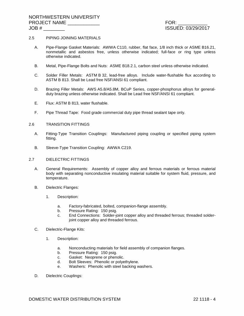
NORTHWESTERN UNIVERSITY PROJECT NAME ____________ FOR: ___________ JOB # ________ ISSUED: 03/29/2017
DOMESTIC WATER DISTRIBUTION SYSTEM 22 1118 - 4
2.5 PIPING JOINING MATERIALS
A. Pipe-Flange Gasket Materials: AWWA C110, rubber, flat face, 1/8 inch thick or ASME B16.21, nonmetallic and asbestos free, unless otherwise indicated; full-face or ring type unless otherwise indicated.
B. Metal, Pipe-Flange Bolts and Nuts: ASME B18.2.1, carbon steel unless otherwise indicated.
C. Solder Filler Metals: ASTM B 32, lead-free alloys. Include water-flushable flux according to ASTM B 813. Shall be Lead free NSF/ANSI 61 compliant.
D. Brazing Filler Metals: AWS A5.8/A5.8M, BCuP Series, copper-phosphorus alloys for general-duty brazing unless otherwise indicated. Shall be Lead free NSF/ANSI 61 compliant.
E. Flux: ASTM B 813, water flushable.
F. Pipe Thread Tape: Food grade commercial duty pipe thread sealant tape only.
2.6 TRANSITION FITTINGS
A. Fitting-Type Transition Couplings: Manufactured piping coupling or specified piping system fitting.
B. Sleeve-Type Transition Coupling: AWWA C219.
2.7 DIELECTRIC FITTINGS
A. General Requirements: Assembly of copper alloy and ferrous materials or ferrous material body with separating nonconductive insulating material suitable for system fluid, pressure, and temperature.
B. Dielectric Flanges:
1. Description:
a. Factory-fabricated, bolted, companion-flange assembly. b. Pressure Rating: 150 psig. c. End Connections: Solder-joint copper alloy and threaded ferrous; threaded solder-
joint copper alloy and threaded ferrous.
C. Dielectric-Flange Kits:
1. Description:
a. Nonconducting materials for field assembly of companion flanges. b. Pressure Rating: 150 psig. c. Gasket: Neoprene or phenolic. d. Bolt Sleeves: Phenolic or polyethylene. e. Washers: Phenolic with steel backing washers.
D. Dielectric Couplings:

NORTHWESTERN UNIVERSITY PROJECT NAME ____________ FOR: ___________ JOB # ________ ISSUED: 03/29/2017
DOMESTIC WATER DISTRIBUTION SYSTEM 22 1118 - 5
1. Description:
a. Galvanized-steel coupling. b. Pressure Rating: 300 psig at 225 deg F. c. End Connections: Female threaded. d. Lining: Inert and noncorrosive, thermoplastic.
E. Dielectric Nipples:
1. Description:
a. Electroplated steel nipple complying with ASTM F 1545. b. Pressure Rating: 300 psig at 225 deg F. c. End Connections: Male threaded or grooved. d. Lining: Inert and noncorrosive, propylene.
2.8 FLEXIBLE CONNECTORS
A. Bronze-Hose Flexible Connectors: Corrugated-bronze tubing with bronze wire-braid covering and ends brazed to inner tubing.
1. Working-Pressure Rating: Minimum 200 psig (1380 kPa). 2. End Connections NPS 2 (DN 50) and Smaller: Threaded copper pipe or plain-end copper
tube. 3. End Connections NPS 2-1/2 (DN 65) and Larger: Flanged copper alloy.
B. Stainless-Steel-Hose Flexible Connectors: Corrugated-stainless-steel tubing with stainless-steel wire-braid covering and ends welded to inner tubing.
1. Working-Pressure Rating: Minimum 200 psig (1380 kPa). 2. End Connections NPS 2 (DN 50) and Smaller: Threaded stainless steel pipe nipple. 3. End Connections NPS 2-1/2 (DN 65) and Larger: Flanged stainless steel pipe nipple.
C. Manufacturers: Subject to compliance with requirements, provide products by one of the following:
1. Flex-Hose. 2. Flexicraft. 3. Hyspan. 4. Flex Precision.
2.9 ENCASEMENT FOR PIPING
A. Standard: ASTM A 674 or AWWA C105/A21.5.
B. Form: [Sheet] [or] [tube].
C. Color: [Black] [or] [natural] <Insert color>.
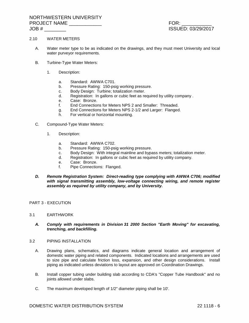
NORTHWESTERN UNIVERSITY PROJECT NAME ____________ FOR: ___________ JOB # ________ ISSUED: 03/29/2017
DOMESTIC WATER DISTRIBUTION SYSTEM 22 1118 - 6
2.10 WATER METERS
A. Water meter type to be as indicated on the drawings, and they must meet University and local water purveyor requirements.
B. Turbine-Type Water Meters:
1. Description:
a. Standard: AWWA C701. b. Pressure Rating: 150-psig working pressure. c. Body Design: Turbine; totalization meter. d. Registration: In gallons or cubic feet as required by utility company . e. Case: Bronze. f. End Connections for Meters NPS 2 and Smaller: Threaded. g. End Connections for Meters NPS 2-1/2 and Larger: Flanged. h. For vertical or horizontal mounting.
C. Compound-Type Water Meters:
1. Description:
a. Standard: AWWA C702. b. Pressure Rating: 150-psig working pressure. c. Body Design: With integral mainline and bypass meters; totalization meter. d. Registration: In gallons or cubic feet as required by utility company. e. Case: Bronze. f. Pipe Connections: Flanged.
D. Remote Registration System: Direct-reading type complying with AWWA C706; modified with signal transmitting assembly, low-voltage connecting wiring, and remote register assembly as required by utility company, and by University.
PART 3 - EXECUTION
3.1 EARTHWORK
A. Comply with requirements in Division 31 2000 Section "Earth Moving" for excavating, trenching, and backfilling.
3.2 PIPING INSTALLATION
A. Drawing plans, schematics, and diagrams indicate general location and arrangement of domestic water piping and related components. Indicated locations and arrangements are used to size pipe and calculate friction loss, expansion, and other design considerations. Install piping as indicated unless deviations to layout are approved on Coordination Drawings.
B. Install copper tubing under building slab according to CDA's "Copper Tube Handbook" and no joints allowed under slabs.
C. The maximum developed length of 1/2" diameter piping shall be 10'.

NORTHWESTERN UNIVERSITY PROJECT NAME ____________ FOR: ___________ JOB # ________ ISSUED: 03/29/2017
DOMESTIC WATER DISTRIBUTION SYSTEM 22 1118 - 7
D. Install ductile-iron piping under building slab with restrained joints according to AWWA C600 and AWWA M41.
E. Install underground [copper tube] [and] [ductile-iron pipe] in PE encasement according to ASTM A 674 or AWWA C105/A21.5.
F. No joints or fittings in lines below floors after the facility water entry assembly.
G. Install shutoff valve, hose-end drain valve, strainer, pressure gage, and test tee with valve, inside the building at each domestic water service entrance. Comply with requirements in Division 22 Section "Meters and Gages for Plumbing Piping" for pressure gages and Division 22 Section "Plumbing Specialties" for drain valves and strainers.
H. Install shutoff valve immediately upstream of each dielectric fitting.
I. Install domestic water piping level and plumb.
J. Rough-in domestic water piping for water-meter installation according to utility company's requirements.
K. Install piping concealed from view and protected from physical contact by building occupants unless otherwise indicated and except in equipment rooms and service areas.
L. Install piping indicated to be exposed and piping in equipment rooms and service areas at right angles or parallel to building walls. Diagonal runs are prohibited unless specifically indicated otherwise.
M. Install piping above accessible ceilings to allow sufficient space for ceiling panel removal, and coordinate with other services occupying that space.
N. Install piping adjacent to equipment and specialties to allow service and maintenance.
O. Install piping to permit valve servicing.
P. Install nipples, unions, special fittings, and valves with pressure ratings the same as or higher than system pressure rating used in applications below unless otherwise indicated.
Q. Install piping free of sags and bends.
R. Install fittings for changes in direction and branch connections.
S. Install unions in copper tubing at final connection to each piece of equipment, machine, and specialty.
T. Provide proper access to components and work that require inspection, repair, service, or maintenance.
U. No piping with a fluid shall be routed over electrical busway housings. For electrical busway housings, provide a minimum 36" inches on top, both sides, and the bottom.
V. Install pressure gages on suction and discharge piping from each plumbing pump and packaged booster pump. Comply with requirements in Division 22 Section "Meters and Gages for Plumbing Piping" for pressure gages.

NORTHWESTERN UNIVERSITY PROJECT NAME ____________ FOR: ___________ JOB # ________ ISSUED: 03/29/2017
DOMESTIC WATER DISTRIBUTION SYSTEM 22 1118 - 8
W. Install thermometers on inlet and outlet piping from each water heater. Comply with requirements in Division 22 Section "Meters and Gages for Plumbing Piping" for thermometers.
X. Install sleeves for piping penetrations of walls, ceilings, and floors. Comply with requirements for sleeves specified in Division 22 Section "Common Work Results for Plumbing."
Y. Install sleeve seals for piping penetrations of concrete walls and slabs. Comply with requirements for sleeve seals specified in Division 22 Section "Common Work Results for Plumbing."
Z. Install escutcheons for piping penetrations of walls, ceilings, and floors. Comply with requirements for escutcheons specified in Division 22 Section "Common Work Results for Plumbing."
3.3 JOINT CONSTRUCTION
A. Ream ends of pipes and tubes and remove burrs. Bevel plain ends of steel pipe.
B. Remove scale, slag, dirt, and debris from inside and outside of pipes, tubes, and fittings before assembly.
C. Threaded Joints: Thread pipe with tapered pipe threads according to ASME B1.20.1. Cut threads full and clean using sharp dies. Ream threaded pipe ends to remove burrs and restore full ID. Join pipe fittings and valves as follows:
1. Apply appropriate tape or thread compound to external pipe threads. 2. Damaged Threads: Do not use pipe or pipe fittings with threads that are corroded or
damaged.
D. Brazed Joints: Join copper tube and fittings according to CDA's "Copper Tube Handbook," "Brazed Joints" Chapter. Shall be Lead free NSF/ANSI 61 compliant.
E. Soldered Joints: Apply ASTM B 813, water-flushable flux to end of tube. Join copper tube and fittings according to ASTM B 828 or CDA's "Copper Tube Handbook." Shall be Lead free NSF/ANSI 61 compliant.
F. Joint Construction for Grooved-End Copper Tubing: Make joints according to AWWA C606. Roll groove ends of tubes. Lubricate and install gasket over ends of tubes or tube and fitting. Install coupling housing sections over gasket with keys seated in tubing grooves. Install and tighten housing bolts.
G. Joint Construction for Grooved-End, Ductile-Iron Piping: Make radius cut joints according to AWWA C606. Cut round-bottom grooves in ends of pipe at gasket-seat dimension required for specified (flexible or rigid) joint. Lubricate and install gasket over ends of pipes or pipe and fitting. Install coupling housing sections over gasket with keys seated in piping grooves. Install and tighten housing bolts.
H. Flanged Joints: Select appropriate asbestos-free, nonmetallic gasket material in size, type, and thickness suitable for domestic water service. Join flanges with gasket and bolts according to ASME B31.9.
I. Dissimilar-Material Piping Joints: Make joints using adapters compatible with materials of both piping systems.

NORTHWESTERN UNIVERSITY PROJECT NAME ____________ FOR: ___________ JOB # ________ ISSUED: 03/29/2017
DOMESTIC WATER DISTRIBUTION SYSTEM 22 1118 - 9
J. Grooved Joints for Copper Piping: Roll grooves in ends of pipe based on pipe and coupling manufacturer's written instructions for pipe wall thickness. The gasket style and elastomeric material (grade) shall be verified as suitable for the intended service as specified. Grooved end shall be clean and free from indentations, projections, and roll marks in the area from pipe end to groove. A representative shall provide on-site training for contractor's field personnel. Contractor shall remove and replace any improperly installed products.
3.4 VALVE INSTALLATION
A. General-Duty Valves: Comply with requirements in Division 22 Section "General-Duty Valves for Plumbing Piping" for valve installations. Shall be Lead free NSF/ANSI 61 compliant.
B. Install shutoff valve close to water main on each branch and riser serving plumbing fixtures or equipment, on each water supply to equipment, and on each water supply to plumbing fixtures that do not have supply stops. Use ball valves for piping NPS 2 and smaller. Use OS&Y or NRS gate valves for piping NPS 2-1/2 and larger.
C. Install drain valves for equipment at base of each water riser, at low points in horizontal piping, and where required to drain water piping. Drain valves are specified in Division 22 Section "Domestic Water Piping Specialties."
1. Hose-End Drain Valves: At low points in water mains, risers, and branches. 2. Stop-and-Waste Drain Valves: Instead of hose-end drain valves where indicated.
D. Install balancing valve in each hot-water circulation return branch and discharge side of each pump and circulator. Set balancing valves partly open to restrict but not stop flow. Use ball valves for piping NPS 2 and smaller and butterfly valves for piping NPS 2-1/2 and larger. Comply with requirements in Division 22 Section "Domestic Water Piping Specialties" for balancing valves.
E. For isolation valves at water heaters, install valves that relieve heater pressure when closed.
3.5 TRANSITION FITTING INSTALLATION
A. Install transition couplings at joints of dissimilar piping.
B. Transition Fittings in Aboveground Domestic Water Piping NPS 2 and Smaller: Plastic-to-metal transition [fittings] [or] [unions].
C. Transition Fittings in Underground Domestic Water Piping:
1. NPS 1-1/2 and Smaller: Fitting-type coupling. 2. NPS 2 and Larger: Sleeve-type coupling.
3.6 DIELECTRIC FITTING INSTALLATION
A. Install dielectric fittings in piping at connections of dissimilar metal piping and tubing. Shall be Lead free NSF/ANSI 61 compliant.
B. Dielectric Fittings for NPS 2 and Smaller: Use dielectric couplings or nipples.
C. Dielectric Fittings for NPS 2-1/2 to NPS 4: Use dielectric flanges.

NORTHWESTERN UNIVERSITY PROJECT NAME ____________ FOR: ___________ JOB # ________ ISSUED: 03/29/2017
DOMESTIC WATER DISTRIBUTION SYSTEM 22 1118 - 10
D. Dielectric Fittings for NPS 5 to NPS 6: Use dielectric flange kits.
3.7 FLEXIBLE CONNECTOR INSTALLATION
A. Install flexible connectors in suction and discharge piping connections to each domestic water pump and in suction and discharge manifold connections to each domestic water booster pump.
B. Install bronze-hose flexible connectors in copper domestic water tubing.
C. Install stainless-steel-hose flexible connectors in non-copper domestic water piping.
3.8 WATER METER INSTALLATION
A. Rough-in domestic water piping, and install water meter as indicated on the drawings according to AWWA M6 and the utility company's requirements.
B. Install water meters with shutoff valves on water-meter inlet and outlet. Provide a valved bypass around meter only if required by the utility company. Support meters, valves, and piping on brick or concrete piers.
C. Install remote registration system according to standards of University, utility company, and of authorities having jurisdiction.
3.9 HANGER AND SUPPORT INSTALLATION
A. Comply with requirements in Division 22 Section "Hangers and Supports for Plumbing Piping and Equipment" for pipe hanger and support products and installation.
1. Vertical Piping: MSS Type 8 or 42, clamps. 2. Individual, Straight, Horizontal Piping Runs:
a. 100 Feet and Less: MSS Type 1, adjustable, steel clevis hangers. b. Longer Than 100 Feet: MSS Type 43, adjustable roller hangers.
3. Base of Vertical Piping: MSS Type 52, spring hangers.
B. Support vertical piping and tubing at base and at each floor.
C. Rod diameter may be reduced one size for double-rod hangers, to a minimum of 3/8 inch.
D. Install hangers for copper tubing with the following maximum horizontal spacing and minimum rod diameters:
1. NPS 3/4 and Smaller: 60 inches with 3/8-inch rod. 2. NPS 1 and NPS 1-1/4: 72 inches with 3/8-inch rod. 3. NPS 1-1/2 and NPS 2: 96 inches with 3/8-inch rod. 4. NPS 2-1/2: 108 inches with 1/2-inch rod. 5. NPS 3 to NPS 5: 10 feet with 1/2-inch rod. 6. NPS 6: 10 feet with 5/8-inch rod.
E. Install supports for vertical copper tubing every 10 feet.

NORTHWESTERN UNIVERSITY PROJECT NAME ____________ FOR: ___________ JOB # ________ ISSUED: 03/29/2017
DOMESTIC WATER DISTRIBUTION SYSTEM 22 1118 - 11
F. Install hangers for ductile iron piping with the following maximum horizontal spacing and minimum rod diameters:
1. NPS 3: 12 feet with 1/2-inch rod. 2. NPS 4: 12 feet with 5/8-inch rod. 3. NPS 6: 12 feet with 3/4-inch rod. 4. NPS 8 and Larger: 12 feet with 3/4-inch rod.
G. Install supports for vertical ductile iron piping every 15 feet.
3.10 CONNECTIONS
A. Drawings indicate general arrangement of piping, fittings, and specialties.
B. Install piping adjacent to equipment and machines to allow service and maintenance.
C. Connect domestic water piping to water-service piping at a point 1’-0” above finished floor or 1’-0” inside the exterior wall, as shown on the drawings, with a shutoff valve using a transition fitting to join dissimilar piping materials then extend and connect to the following:
1. Water Heaters: Cold-water inlet and hot-water outlet piping in sizes indicated, but not smaller than sizes of water heater connections.
2. Plumbing Fixtures: Cold- and hot-water supply piping in sizes indicated, but not smaller than required by plumbing code. Comply with requirements in Division 22 plumbing fixture Sections for connection sizes.
3. Equipment: Cold- and hot-water supply piping as indicated, but not smaller than equipment connections. Provide shutoff valve and union for each connection. Use flanges instead of unions for NPS 2-1/2 and larger.
3.11 IDENTIFICATION
A. Identify system components. Comply with requirements in Division 22 Section "Identification for Plumbing Piping and Equipment" for identification materials and installation.
B. Label pressure piping with system operating pressure.
3.12 FIELD QUALITY CONTROL
A. Perform tests and inspections.
B. Piping Inspections:
1. Do not enclose, cover, or put piping into operation until it has been inspected and approved by authorities having jurisdiction, FMDC and FMO.
2. During installation, notify authorities having jurisdiction at least one day before inspection must be made. Perform tests specified below in presence of authorities having jurisdiction:
a. Roughing-in Inspection: Arrange for inspection of piping before concealing or closing-in after roughing-in and before setting fixtures.
b. Final Inspection: Arrange final inspection for authorities having jurisdiction to observe tests specified below and to ensure compliance with requirements.
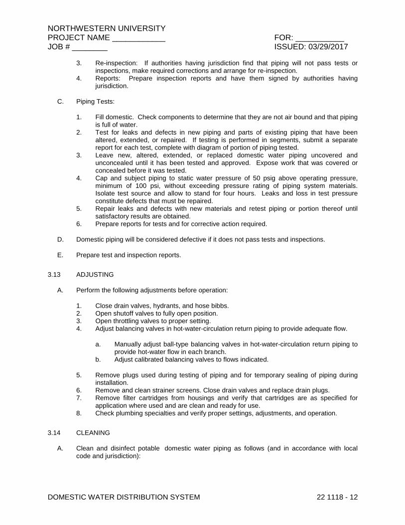
NORTHWESTERN UNIVERSITY PROJECT NAME ____________ FOR: ___________ JOB # ________ ISSUED: 03/29/2017
DOMESTIC WATER DISTRIBUTION SYSTEM 22 1118 - 12
3. Re-inspection: If authorities having jurisdiction find that piping will not pass tests or inspections, make required corrections and arrange for re-inspection.
4. Reports: Prepare inspection reports and have them signed by authorities having jurisdiction.
C. Piping Tests:
1. Fill domestic. Check components to determine that they are not air bound and that piping is full of water.
2. Test for leaks and defects in new piping and parts of existing piping that have been altered, extended, or repaired. If testing is performed in segments, submit a separate report for each test, complete with diagram of portion of piping tested.
3. Leave new, altered, extended, or replaced domestic water piping uncovered and unconcealed until it has been tested and approved. Expose work that was covered or concealed before it was tested.
4. Cap and subject piping to static water pressure of 50 psig above operating pressure, minimum of 100 psi, without exceeding pressure rating of piping system materials. Isolate test source and allow to stand for four hours. Leaks and loss in test pressure constitute defects that must be repaired.
5. Repair leaks and defects with new materials and retest piping or portion thereof until satisfactory results are obtained.
6. Prepare reports for tests and for corrective action required.
D. Domestic piping will be considered defective if it does not pass tests and inspections.
E. Prepare test and inspection reports.
3.13 ADJUSTING
A. Perform the following adjustments before operation:
1. Close drain valves, hydrants, and hose bibbs. 2. Open shutoff valves to fully open position. 3. Open throttling valves to proper setting. 4. Adjust balancing valves in hot-water-circulation return piping to provide adequate flow.
a. Manually adjust ball-type balancing valves in hot-water-circulation return piping to provide hot-water flow in each branch.
b. Adjust calibrated balancing valves to flows indicated.
5. Remove plugs used during testing of piping and for temporary sealing of piping during installation.
6. Remove and clean strainer screens. Close drain valves and replace drain plugs. 7. Remove filter cartridges from housings and verify that cartridges are as specified for
application where used and are clean and ready for use. 8. Check plumbing specialties and verify proper settings, adjustments, and operation.
3.14 CLEANING
A. Clean and disinfect potable domestic water piping as follows (and in accordance with local code and jurisdiction):
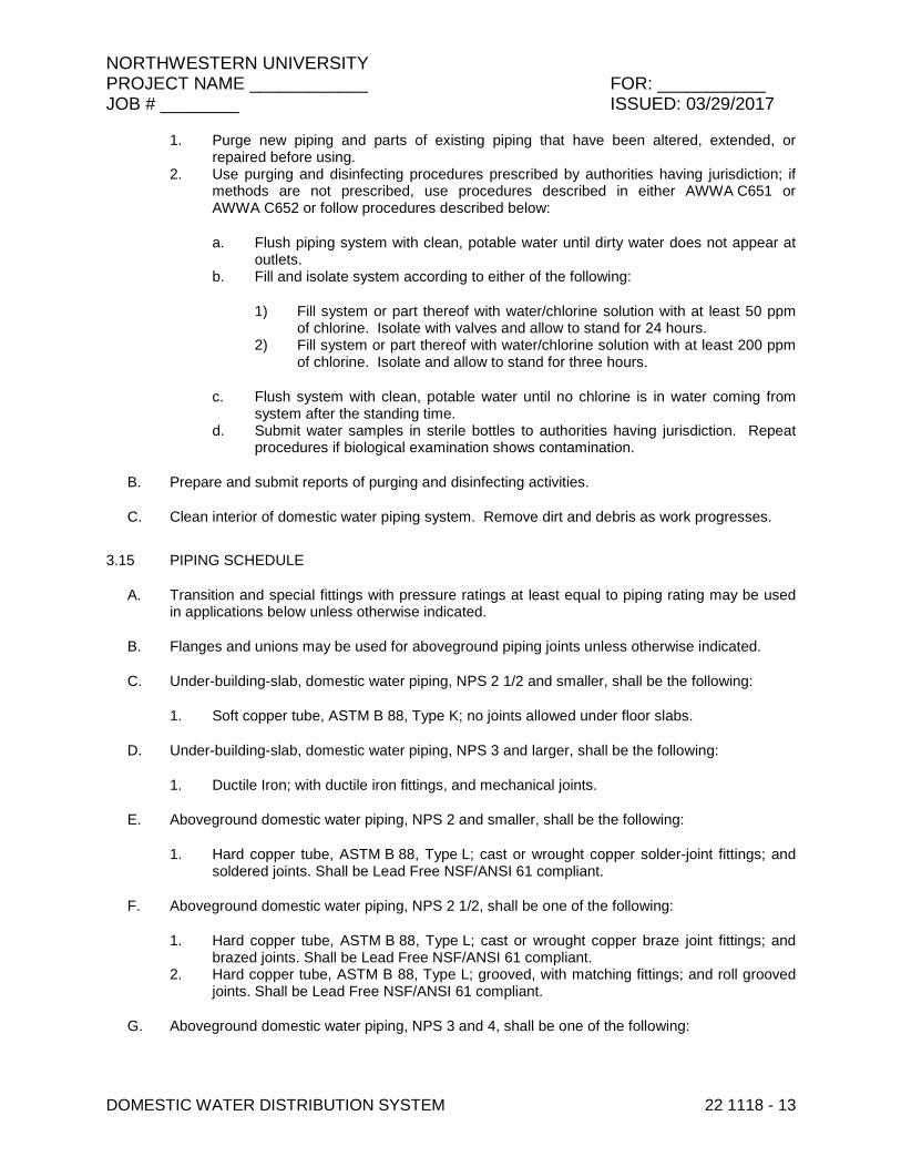
NORTHWESTERN UNIVERSITY PROJECT NAME ____________ FOR: ___________ JOB # ________ ISSUED: 03/29/2017
DOMESTIC WATER DISTRIBUTION SYSTEM 22 1118 - 13
1. Purge new piping and parts of existing piping that have been altered, extended, or repaired before using.
2. Use purging and disinfecting procedures prescribed by authorities having jurisdiction; if methods are not prescribed, use procedures described in either AWWA C651 or AWWA C652 or follow procedures described below:
a. Flush piping system with clean, potable water until dirty water does not appear at outlets.
b. Fill and isolate system according to either of the following:
1) Fill system or part thereof with water/chlorine solution with at least 50 ppm of chlorine. Isolate with valves and allow to stand for 24 hours.
2) Fill system or part thereof with water/chlorine solution with at least 200 ppm of chlorine. Isolate and allow to stand for three hours.
c. Flush system with clean, potable water until no chlorine is in water coming from system after the standing time.
d. Submit water samples in sterile bottles to authorities having jurisdiction. Repeat procedures if biological examination shows contamination.
B. Prepare and submit reports of purging and disinfecting activities.
C. Clean interior of domestic water piping system. Remove dirt and debris as work progresses.
3.15 PIPING SCHEDULE
A. Transition and special fittings with pressure ratings at least equal to piping rating may be used in applications below unless otherwise indicated.
B. Flanges and unions may be used for aboveground piping joints unless otherwise indicated.
C. Under-building-slab, domestic water piping, NPS 2 1/2 and smaller, shall be the following:
1. Soft copper tube, ASTM B 88, Type K; no joints allowed under floor slabs.
D. Under-building-slab, domestic water piping, NPS 3 and larger, shall be the following:
1. Ductile Iron; with ductile iron fittings, and mechanical joints.
E. Aboveground domestic water piping, NPS 2 and smaller, shall be the following:
1. Hard copper tube, ASTM B 88, Type L; cast or wrought copper solder-joint fittings; and soldered joints. Shall be Lead Free NSF/ANSI 61 compliant.
F. Aboveground domestic water piping, NPS 2 1/2, shall be one of the following:
1. Hard copper tube, ASTM B 88, Type L; cast or wrought copper braze joint fittings; and brazed joints. Shall be Lead Free NSF/ANSI 61 compliant.
2. Hard copper tube, ASTM B 88, Type L; grooved, with matching fittings; and roll grooved joints. Shall be Lead Free NSF/ANSI 61 compliant.
G. Aboveground domestic water piping, NPS 3 and 4, shall be one of the following:
NORTHWESTERN UNIVERSITY PROJECT NAME ____________ FOR: ___________ JOB # ________ ISSUED: 03/29/2017
DOMESTIC WATER DISTRIBUTION SYSTEM 22 1118 - 14
1. Hard copper tube, ASTM B 88, Type L; cast or wrought copper braze-joint fittings; and brazed joints. Shall be Lead Free NSF/ANSI 61 compliant.
2. Hard copper tube, ASTM B 88, Type L; grooved, with matching fittings; and roll grooved joints. Shall be Lead Free NSF/ANSI 61 compliant.
3. Ductile Iron; with ductile iron fittings, and mechanical or grooved joints. Shall be Lead Free NSF/ANSI 61 compliant.
H. Aboveground domestic water piping, NPS 6 and Larger, shall be the following:
1. Ductile Iron; with ductile iron fittings, and mechanical or grooved joints. 2. Galvanized pipe with mechanical joints.
3.16 VALVE SCHEDULE (Including Access to Same)
A. Drawings indicate valve types to be used. Where specific valve types are not indicated, the following requirements apply:
1. Shutoff Duty: Use ball valves for piping NPS 2 and smaller. Use OS&Y or NRS gate valves or ball valves with flanged ends for piping NPS 2-1/2 and larger (ball valves only to 3"). Shall be Lead Free NSF/ANSI 61 compliant.
2. Throttling Duty: Use ball valves for piping NPS 2 and smaller. Shall be Lead Free NSF/ANSI 61 compliant.
3. Hot-Water Circulation Piping, Balancing Duty: Memory-stop balancing valves. 4. Drain Duty: Hose-end drain valves. Shall be Lead Free NSF/ANSI 61 compliant. 5. Faucets and fixtures, such as emergency showers, eyewashes, dishwashers, and
autoclaves, shall have local shutoff valves within 5' of the faucet/fixture. Valves must be readily accessible. Shall be Lead Free NSF/ANSI 61 compliant.
6. Shut-off isolation valves shall be provided on the branch lines no more than 18" off of the main lines or risers. Additional shut-off isolation valves may be needed further down the branch lines also, and are to be provided to the satisfaction of the University. Shall be Lead Free NSF/ANSI 61 compliant.
B. Iron grooved-end valves may be used with grooved-end piping. Shall be Lead Free NSF/ANSI 61 compliant.
C. Access panels shall be provided for any plumbing valves that may be in walls or in-accessible ceilings. Access panels shall be a minimum of 12" x 12".
END OF SECTION 22 1118

NORTHWESTERN UNIVERSITY PROJECT NAME ____________ FOR: ___________ JOB # ________ ISSUED: 03/29/2017
DOMESTIC WATER DISTRIBUTION SYSTEM 22 1118 - 15
THIS PAGE IS INTENTIONALLY BLANK

NORTHWESTERN UNIVERSITY PROJECT NAME ____________ FOR: ___________ JOB # ________ ISSUED: 03/29/2017
PLUMBING SPECIALTIES 22 1119 - 1
SECTION 22 1119 - PLUMBING SPECIALTIES
PART 1 - GENERAL
1.1 RELATED DOCUMENTS
A. Drawings and general provisions of the Contract, including General and Supplementary Conditions and Division 01 Specification Sections, apply to this Section.
1.2 SUMMARY
A. This Section includes the following domestic water piping specialties:
1. Vacuum breakers. 2. Backflow preventers. 3. Water pressure-reducing valves. 4. Balancing valves. 5. Temperature-actuated water mixing valve stations. 6. Electronic water mixing valve stations. 7. Strainers. 8. Hose bibbs. 9. Wall hydrants. 10. Drain valves. 11. Water hammer arresters. 12. Trap-seal primer valves.
B. Related Sections include the following:
1. Division 21 sections where water supply to fire suppression systems is required. 2. See all other Division 22 Sections.
1.3 PERFORMANCE REQUIREMENTS
A. Minimum Working Pressure for Domestic Water Piping Specialties: 125 psig, unless otherwise indicated.
1.4 SUBMITTALS
A. Product Data: For each type of product indicated.
B. Field quality-control test reports.
C. Operation and maintenance data.
D. At closeout, Northwestern University Maintenance Requirement Forms, see Division 01 for more information.
NORTHWESTERN UNIVERSITY PROJECT NAME ____________ FOR: ___________ JOB # ________ ISSUED: 03/29/2017
PLUMBING SPECIALTIES 22 1119 - 2
1.5 QUALITY ASSURANCE
A. Comply with California Health and Safety Code 116875 (AB 1953) - 2010, for 25% low lead content of piping, pipe fittings, and faucets for water intended for human consumption, and NSF/ANSI Standard 61, including Annex G-2010 - Drinking Water System Components - Low Lead Content Requirement.
B. Other NSF Compliance:
1. Comply with NSF 14, "Plastics Piping Components and Related Materials," for plastic domestic water piping components.
1.6 SPECIAL WARRANTIES
A. Five (5) years, see Division 01 for more information.
PART 2 - PRODUCTS
2.1 BACKFLOW PREVENTERS & VACUUM BREAKERS
A. Manufacturers: Subject to compliance with requirements, provide products by Conbraco, no others allowed.
B. Pipe-Applied, Atmospheric-Type Vacuum Breakers for Plumbing Use:
1. Standard: ASSE 1001. 2. Size: As required to match connected piping. 3. Body: Bronze. 4. Finish: Rough bronze. 5. Lead free NSF/ANSI 61 compliant
C. Intermediate Atmospheric-Vent Backflow Preventers for Vending and Coffee Stations:
1. Standard: ASSE 1012. 2. Operation: Continuous-pressure applications. 3. Body: Bronze. 4. Finish: Rough bronze. 5. Lead free NSF/ANSI 61 compliant
D. Reduced-Pressure-Principle Backflow Preventers for Plumbing Use:
1. The reduced pressure zone assembly shall be C89836 lead-free and consist of two independent torsion spring check modules, a differential pressure relief valve located between and below the two modules, two drip tight shutoff valves, and required torsion spring check modules and relief valve shall be contained with a sleeve accessible single housing constructed from stainless steel in sizes 2.5" -8", and from FDA epoxy coated ductile iron for 10" and 12" sizes. Provide with NRS gate or OSY gate valves with either flanged or grooved end pipe connections on larger sizes, but smaller sizes to have ball valves with stainless balls and stems if available. Butterfly valves are not acceptable.

NORTHWESTERN UNIVERSITY PROJECT NAME ____________ FOR: ___________ JOB # ________ ISSUED: 03/29/2017
PLUMBING SPECIALTIES 22 1119 - 3
2. Torsion spring checks shall have replaceable chloramine resistant silicone discs and in operation, produce drip tight closure against the reverse flow of liquid caused by backpressure or back-siphonage.
3. ASSE 1047 approved. 4. Basis of Design - Conbraco RPDALF4 .
E. Reduced Pressure Detector Backflow Preventers for Supply of Fire Suppression Systems:
1. See applicable Division 21 sections. Backflow preventers for supply of fire suppression systems are furnished and installed by the project Plumbing Contractor. Conbraco only for manufacturer.
F. Backflow-Preventer Test Kits:
1. Description: Factory calibrated, with gages, fittings, hoses, and carrying case with test-procedure instructions.
2.2 WATER PRESSURE-REDUCING VALVES
A. Water Regulators:
1. Manufacturers: Subject to compliance with requirements, provide products by one of the following:
a. Conbraco
2. Standard: ASSE 1003. 3. Pressure Rating: Initial working pressure of 150 psig. 4. Body: Bronze with chrome-plated finish for NPS 2 and smaller; cast iron with interior
lining complying with AWWA C550 or that is FDA approved for NPS 2-1/2 and larger. 5. Valves for Dishwasher Booster Heater Water Supplies: Include integral bypass. 6. End Connections: Threaded for NPS 2 and smaller; flanged for NPS 2-1/2 and larger. 7. Lead free NSF/ANSI 61 compliant
2.3 BALANCING VALVES
A. Memory-Stop Balancing Valves:
1. Manufacturers: Subject to compliance with requirements, provide products by one of the following:
a. Conbraco
2. Standard: MSS SP-110 for two-piece, copper-alloy ball valves. 3. Pressure Rating: 400-psig minimum CWP. 4. Size: NPS 2 or smaller. 5. Body: Copper alloy. 6. Port: Standard or full port. 7. Ball: Chrome-plated brass. 8. Seats and Seals: Replaceable. 9. End Connections: Solder joint or threaded. 10. Handle: Vinyl-covered steel with memory-setting device. 11. Lead free NSF/ANSI 61 compliant

NORTHWESTERN UNIVERSITY PROJECT NAME ____________ FOR: ___________ JOB # ________ ISSUED: 03/29/2017
PLUMBING SPECIALTIES 22 1119 - 4
2.4 TEMPERATURE-ACTUATED WATER MIXING VALVE STATIONS
A. Primary, Thermostatic, Water Mixing Valve Stations:
1. Manufacturers: Subject to compliance with requirements, provide products by one of the following:
a. Holby. b. Or approved equal.
2. Description: Complete factory preassembled, high/low, ASSE 1017, lead free, water temperature control station mounted on heavy duty welded strut frame for wall mounting including piping, valving, and gages.
a. Type: Exposed-mounting, thermostatically controlled water mixing valve assembly.
b. Materials: Bronze body with corrosion-resistant interior components, and copper piping.
c. Connections: Threaded or soldered. d. Accessories/features: Manual adjustments, bi-metal thermostat, color coded dials,
locking temperature regulating valves, adjustable limit stops, check stops on hot- and cold-water supplies, outlet ball valves, factory tested, and temperature gauge.
e. Valve Pressure Rating: 125 psig minimum, unless otherwise indicated. Delete line below only if flow rate is indicated on Drawings.
f. Tempered-Water Design Flow Rate: See drawings. g. Valve Finish: Rough bronze. h. Controls: Aquastat and wiring box including red and green operating lights, GFCI
switch. i. If called for on drawings, provide with stainless steel cabinet, building management
system interface, and/or test connection piping on outlet. j. Install a valved bypass around mixing assembly. k. Lead free NSF/ANSI 61 compliant
2.5 ELECTRONIC WATER MIXING VALVE STATIONS
A. Primary, Thermostatic, Water Mixing Valve Stations:
1. Manufacturers: Subject to compliance with requirements, provide products by one of the following:
a. Armstrong Brain. b. Or approved equal.
2. Description: Complete factory preassembled, high/low, ASSE 1017, lead free, water temperature control station mounted on heavy duty welded strut frame for wall mounting including piping, valving, and gages.
a. Type: Exposed-mounting, thermostatically controlled water mixing valve assembly.
b. Materials: Bronze body with corrosion-resistant interior components, and copper piping.
c. Connections: Threaded or soldered.

NORTHWESTERN UNIVERSITY PROJECT NAME ____________ FOR: ___________ JOB # ________ ISSUED: 03/29/2017
PLUMBING SPECIALTIES 22 1119 - 5
d. Accessories/features: Manual adjustments, bi-metal thermostat, color coded dials, locking temperature regulating valves, adjustable limit stops, check stops on hot- and cold-water supplies, outlet ball valves, factory tested, and temperature gauge.
e. Valve Pressure Rating: 125 psig minimum, unless otherwise indicated. Delete line below only if flow rate is indicated on Drawings.
f. Tempered-Water Design Flow Rate: See drawings. g. Valve Finish: Rough bronze. h. Controls: Aquastat and wiring box including red and green operating lights, GFCI
switch. i. If called for on drawings, provide with stainless steel cabinet, building management
system interface, and/or test connection piping on outlet. j. Install a valved bypass around mixing assembly. k. Lead free NSF/ANSI 61 compliant
2.6 HOSE BIBBS
A. Hose Bibbs (HB):
1. Manufacturers: Subject to compliance with requirements, provide the product indicated on the drawings or a comparable product by one of the following:
a. Chicago. b. Arrowhead Brass Products, Inc. c. Woodford Manufacturing Company.
2. Description:
a. Standard: ASME A112.18.1 for sediment faucets. b. Body Material: Bronze. c. Seat: Bronze, replaceable. d. Outlet Connection: Garden-hose thread complying with ASME B1.20.7. e. Vacuum Breaker: Integral nonremovable, drainable, hose-connection vacuum
breaker complying with ASSE 1011. f. Finish: Chrome plated.
2.7 WALL HYDRANTS
A. Non-Freeze Wall Hydrants (WH):
1. Manufacturers: Subject to compliance with requirements, provide the product indicated on the drawings or a comparable product by one of the following:
a. Josam Company. b. Smith, Jay R. Mfg. Co. c. Tyler Pipe; Wade Division. d. Zurn Plumbing Products Group.
2. Standard: ASME A112.21.3M for concealed-outlet, self-draining wall hydrants. 3. Pressure Rating: 125 psig. 4. Operation: Loose key. (One with each wall hydrant.) 5. Casing and Operating Rod: Of length required to match wall thickness with wall clamp. 6. Inlet: NPS 3/4. 7. Outlet: Concealed, with integral vacuum breaker and ASME B1.20.7 garden-hose thread.

NORTHWESTERN UNIVERSITY PROJECT NAME ____________ FOR: ___________ JOB # ________ ISSUED: 03/29/2017
PLUMBING SPECIALTIES 22 1119 - 6
8. Box: Deep, flush mounting with polished nickel bronze cover
2.8 DRAIN VALVES
A. Ball-Valve-Type, Hose-End Drain Valves:
1. Manufacturers: Subject to compliance with requirements, provide products by one of the following:
a. Conbraco.
2. Standard: MSS SP-110 for standard-port, two-piece ball valves. 3. Size: NPS 3/4. 4. Ball: Chrome-plated brass. 5. Seats and Seals: Replaceable. 6. Outlet: Threaded, short nipple with garden-hose thread complying with ASME B1.20.7
and cap with brass chain.
2.9 WATER HAMMER ARRESTERS
A. Water Hammer Arresters:
1. Manufacturers: Subject to compliance with requirements, provide products by one of the following:
a. Josam Company. b. PPP Inc. c. Smith, Jay R. Mfg. Co. d. Zurn Plumbing Products Group.
2. Description:
a. Standard: ASSE 1010 or PDI-WH 201. b. Type: Metal bellows. c. Size: In accordance with PDI-WH 201.
2.10 TRAP-SEAL PRIMER VALVES
A. Supply-Type, Trap-Seal Primer Valves:
1. Manufacturers: Subject to compliance with requirements, provide products by one of the following:
a. PPP Inc. b. Smith, Jay R. Mfg. Co. c. Watts Industries
2. Standard: ASSE 1018. 3. Pressure Rating: 125 psig minimum. 4. Body: Bronze. 5. Inlet and Outlet Connections: NPS 1/2 threaded, union, or solder joint. 6. Gravity Drain Outlet Connection: NPS 1/2 threaded or solder joint.
NORTHWESTERN UNIVERSITY PROJECT NAME ____________ FOR: ___________ JOB # ________ ISSUED: 03/29/2017
PLUMBING SPECIALTIES 22 1119 - 7
7. Finish: Chrome plated, or rough bronze for units used with pipe or tube that is not chrome finished.
2.11 STRAINERS FOR DOMESTIC WATER PIPING
A. Y-Pattern Strainers:
1. Pressure Rating: 125 psig minimum, unless otherwise indicated. 2. Body: Bronze for NPS 2 and smaller; cast iron, FDA-approved, [with epoxy coating] for
NPS 2-1/2 and larger. 3. End Connections: Threaded for NPS 2 and smaller; flanged for NPS 2-1/2 and larger. 4. Screen: Stainless steel with round perforations, unless otherwise indicated. 5. Perforation Size:
a. Strainers NPS 2 and Smaller: 0.020 inch. b. Strainers NPS 2-1/2 to NPS 4: 0.045 inch. c. Strainers NPS 5 and Larger: 0.10 inch.
6. Drain: Pipe plug.
PART 3 - EXECUTION
3.1 INSTALLATION
A. Refer to Division 22 Section "Common Work Results for Plumbing" for piping joining materials, joint construction, and basic installation requirements.
B. Install backflow preventers in each water supply to mechanical equipment and systems and to other equipment and water systems that may be sources of contamination. Comply with authorities having jurisdiction.
1. Locate backflow preventers in same room as connected equipment or system. 2. Install drain for backflow preventers with atmospheric-vent drain connection with air-gap
fitting, fixed air-gap fitting, or equivalent positive pipe separation of at least two pipe diameters in drain piping and pipe to floor drain. Locate air-gap device attached to or under backflow preventer. Simple air breaks are not acceptable for this application.
3. Do not install bypass piping around backflow preventers. 4. At domestic water services 3" and larger that contain a backflow preventer shall
have two backflows for redundancy.
C. Install water pressure regulators with inlet and outlet shutoff valves and bypass with memory-stop balancing valve. Install pressure gages on inlet and outlet.
D. Install balancing valves in locations where they can easily be adjusted.
E. Install temperature-actuated water mixing valve stations in accordance with manufacturers instructions.
F. Install Y-pattern strainers for water on supply side of each control valve, water pressure-reducing valve, solenoid valve, and pump.
NORTHWESTERN UNIVERSITY PROJECT NAME ____________ FOR: ___________ JOB # ________ ISSUED: 03/29/2017
PLUMBING SPECIALTIES 22 1119 - 8
G. Install water hammer arresters in water piping according to PDI-WH 201.
H. Install supply-type, trap-seal primer valves with outlet piping pitched down toward drain trap a minimum of 1 percent, and connect to floor-drain body, trap, or inlet fitting. Adjust valve for proper flow.
I. Piping installation requirements are specified in other Division 22 Sections. Drawings indicate general arrangement of piping and specialties.
J. Distinguish among multiple units, inform operator of operational requirements, indicate safety and emergency precautions, and warn of hazards and improper operations, in addition to identifying unit. Nameplates and signs are specified in Division 22 Section "Identification for Plumbing Piping and Equipment."
3.2 FIELD QUALITY CONTROL
A. Perform the following tests and prepare test reports:
1. Test each reduced-pressure-principle backflow preventer and double-check backflow-prevention assembly according to authorities having jurisdiction and the device's reference standard.
B. Remove and replace malfunctioning domestic water piping specialties and retest as specified above.
3.3 ADJUSTING
A. Set field-adjustable pressure set points of water pressure-reducing valves.
B. Set field-adjustable flow of balancing valves.
C. Set field-adjustable temperature set points of temperature-actuated water mixing valves.
END OF SECTION 22 1114

NORTHWESTERN UNIVERSITY PROJECT NAME ____________ FOR: ___________ JOB # ________ ISSUED: 03/29/2017
SANITARY WASTE AND VENT PIPING 22 1316 - 1
SECTION 22 1316 - SANITARY WASTE AND VENT PIPING
PART 1 - GENERAL
1.1 RELATED DOCUMENTS
A. Drawings and general provisions of the Contract, including General and Supplementary Conditions and Division 01 Specification Sections, apply to this Section.
1.2 SUMMARY
A. This Section includes sanitary drainage inside the building up to a point 5’-0” outside the building and vent piping inside the building including:
1. Pipe and fittings. 2. Special pipe fittings.
1.3 PERFORMANCE REQUIREMENTS
A. Components and installation shall be capable of withstanding the following minimum working pressure, unless otherwise indicated:
1. Soil, Waste, and Vent Piping: 10-foot head of water.
1.4 SUBMITTALS
A. LEED Submittal:
1. Product Data for Credit EQ 4.1: For solvent cements and adhesive primers, including printed statement of VOC content.
B. Field quality-control inspection and test reports.
1.5 QUALITY ASSURANCE
A. Piping materials shall bear label, stamp, or other markings of specified testing agency.
B. Comply with NSF 14, "Plastics Piping Systems Components and Related Materials," for plastic piping components. Include marking with "NSF-DWV" for plastic drain, waste, and vent piping; and "NSF-drain" for plastic drain piping.
1.6 FIELD CONDITIONS
A. Interruption of Existing Sanitary Waste Service: Do not interrupt service to facilities occupied by Owner or others unless permitted under the following conditions and then only after arranging to provide temporary service according to requirements indicated:

NORTHWESTERN UNIVERSITY PROJECT NAME ____________ FOR: ___________ JOB # ________ ISSUED: 03/29/2017
SANITARY WASTE AND VENT PIPING 22 1316 - 2
1. Notify the University no fewer than seven days in advance of proposed interruption of sanitary waste service.
2. Do not proceed with interruption of sanitary waste service without the University’s written permission.
PART 2 - PRODUCTS
2.1 PIPING MATERIALS
A. Hub-and-Spigot, Cast-Iron Pipe and Fittings: ASTM A 74, Service class.
1. Gaskets: ASTM C 564, rubber.
B. Hubless Cast-Iron Pipe and Fittings: ASTM A 888 or CISPI 301.
1. Shielded Couplings: ASTM C 1277 assembly of metal shield or housing, corrosion-resistant fasteners, and rubber sleeve with integral, center pipe stop.
a. Standard, Shielded, Stainless-Steel Couplings: CISPI 310, with stainless-steel corrugated shield; stainless-steel bands and tightening devices; and ASTM C 564, rubber sleeve.
b. Heavy-Duty, Shielded, Stainless-Steel Couplings: With stainless-steel shield, stainless-steel bands and tightening devices, and ASTM C 564, rubber sleeve.
C. Schedule 40 PVC Pipe: ASTM D 2665, solid-wall drain, waste, and vent.
1. PVC Socket Fittings: ASTM D 2665, socket type, made to ASTM D 3311, drain, waste, and vent patterns.
2. Solvent Cement and Adhesive Primer:
a. Use PVC solvent cement that has a VOC content of 510 g/L or less when calculated according to 40 CFR 59, Subpart D (EPA Method 24).
b. Use adhesive primer that has a VOC content of 550 g/L or less when calculated according to 40 CFR 59, Subpart D (EPA Method 24).
D. Steel Pipe: ASTM A 53/A 53M, Type E or S, Grade A or B, Schedule 40, galvanized. Include ends matching joining method.
1. Drainage Fittings: ASME B16.12, galvanized, threaded, cast-iron drainage pattern. 2. Pressure Fittings:
a. Steel Pipe Nipples: ASTM A 733, made of ASTM A 53/A 53M or ASTM A 106, Schedule 40, galvanized, seamless steel pipe. Include ends matching joining method.
b. Malleable-Iron Unions: ASME B16.39; Class 150; hexagonal-stock body with ball-and-socket, metal-to-metal, bronze seating surface; and female threaded ends.
c. Gray-Iron, Threaded Fittings: ASME B16.4, Class 125, galvanized, standard pattern.
d. Cast-Iron Flanges: ASME B16.1, Class 125. e. Cast-Iron, Flanged Fittings: ASME B16.1, Class 125, galvanized.
E. CPVC Drainage Pipe and Fittings: ASTM F 2618 pipe and drainage-pattern fittings.

NORTHWESTERN UNIVERSITY PROJECT NAME ____________ FOR: ___________ JOB # ________ ISSUED: 03/29/2017
SANITARY WASTE AND VENT PIPING 22 1316 - 3
1. Acceptable Manufacturers: Charlotte Chemdrain (Basis of Design) 2. Solvent Cement for Joining CPVC Piping: ASTM F 493. Include primer according to
ASTM F 656.
PART 3 - EXECUTION
3.1 EXCAVATION
A. Refer to Division 31 Section “Earth Moving” for excavating, trenching, and backfilling.
3.2 PIPING APPLICATIONS
A. Special pipe fittings with pressure ratings at least equal to piping pressure ratings may be used in applications below, unless otherwise indicated.
B. Flanges and unions may be used on aboveground pressure piping, unless otherwise indicated.
C. Aboveground, soil & waste piping shall be:
1. Hubless cast-iron soil pipe and fittings; standard, shielded, stainless-steel couplings; and hubless-coupling joints.
D. Aboveground, vent piping shall be one of the following:
1. Hubless cast-iron soil pipe and fittings; standard, shielded, stainless-steel couplings; and hubless-coupling joints.
2. Solid-wall PVC pipe, PVC socket fittings, and solvent-cemented joints.
E. Underground, soil, waste, and vent piping shall be one of the following:
1. Service class, hub-and-spigot, cast-iron soil pipe and fittings; gaskets; and compression joints.
2. Solid-wall Schedule 40 PVC pipe, PVC socket fittings, and solvent-cemented joints.
F. Sewage pump or sump pump discharge piping shall be one of the following:
1. Solid-wall Schedule 40 PVC pipe, PVC socket fittings, and solvent-cemented joints. 2. Schedule 40 galvanized steel pipe with screwed galvanized cat iron drainage fittings.
G. Single-Wall, Chemical-Waste Sewerage Piping: Use the following piping materials for each size range:
1. NPS 1-1/2 to NPS 4 (DN 40 to DN 100): CPVC drainage pipe and fittings and solvent-cemented joints.
H. Underground, Double-Containment, Chemical-Waste Sewerage Piping: Use the following piping materials for each size range:
1. NPS 2 to NPS 12 (DN 50 to DN 300): CPVC double-containment drainage pipe and fittings.
NORTHWESTERN UNIVERSITY PROJECT NAME ____________ FOR: ___________ JOB # ________ ISSUED: 03/29/2017
SANITARY WASTE AND VENT PIPING 22 1316 - 4
I. Aboveground Chemical-Waste Piping: Use the following piping materials for each size range:
1. NPS 1-1/2 to NPS 6 (DN 40 to DN 150): CPVC drainage piping and solvent-cemented joints.
J. PVC piping may not be installed in a return air plenum for any of the above piping applications unless piping is completely insulated in fire retardant insulation rated for return air plenums.
3.3 PIPING INSTALLATION
A. Site sanitary sewer piping to a point 5’-0” outside the building is specified in Division 33 Section "Facility Sanitary Sewers."
B. Basic piping installation requirements are specified in Division 22 Section "Common Work Results for Plumbing."
C. Install cast-iron soil piping according to CISPI's "Cast Iron Soil Pipe and Fittings Handbook," Chapter IV, "Installation of Cast Iron Soil Pipe and Fittings."
D. Install CPVC drainage piping according to ASTM D 2321 and ASTM F 1668.
E. Make changes in direction for soil and waste drainage and vent piping using appropriate branches, bends, and long-sweep bends. Sanitary tees and short-sweep 1/4 bends may be used on vertical stacks if change in direction of flow is from horizontal to vertical. Use long-turn, double Y-branch and 1/8-bend fittings if 2 fixtures are installed back to back or side by side with common drain pipe. Straight tees, elbows, and crosses may be used on vent lines. Do not change direction of flow more than 90 degrees. Use proper size of standard increasers and reducers if pipes of different sizes are connected. Reducing size of drainage piping in direction of flow is prohibited.
F. Lay buried building drainage piping beginning at low point of each system. Install true to grades and alignment indicated, with unbroken continuity of invert. Place hub ends of piping upstream. Install required gaskets according to manufacturer's written instructions for use of lubricants, cements, and other installation requirements. Maintain swab in piping and pull past each joint as completed.
G. Install soil and waste drainage and vent piping at the following minimum slopes, unless otherwise indicated:
1. Sanitary Drains: 2 percent downward in direction of flow for piping NPS 2 and 1 percent downward in direction of flow for piping NPS 3 and larger.
2. Vent Piping: Slope toward vertical fixture vent or toward vent stack.
H. Sleeves are not required for cast-iron soil piping passing through concrete slabs-on-grade if slab is without membrane waterproofing.
I. Install PVC soil and waste drainage and vent piping according to ASTM D 2665 and ASTM D 2321.
J. Do not enclose, cover, or put piping into operation until it is inspected and approved by authorities having jurisdiction.

NORTHWESTERN UNIVERSITY PROJECT NAME ____________ FOR: ___________ JOB # ________ ISSUED: 03/29/2017
SANITARY WASTE AND VENT PIPING 22 1316 - 5
K. Install sleeves for piping penetrations of walls, ceilings, and floors. Comply with requirements for sleeves specified in Division 22 Section "Common Work Results for Plumbing".
L. Install sleeve seals for piping penetrations of concrete walls and slabs. Comply with requirements for sleeve seals specified in Division 22 Section "Common Work Results for Plumbing".
M. Install escutcheons for piping penetrations of walls, ceilings, and floors. Comply with requirements for escutcheons specified in Division 22 Section "Common Work Results for Plumbing".
3.4 VALVE INSTALLATION
A. General-duty valves are specified in Division 22 Section "General-Duty Valves for Plumbing Piping."
B. Shutoff Valves: Install shutoff valve on each sewage pump or sump pump discharge.
C. Check Valves: Install swing check valve, downstream from shutoff valve, on each sewage pump or sump pump discharge.
3.5 JOINT CONSTRUCTION
A. Basic piping joint construction requirements are specified in Division 22 Section "Common Work Results for Plumbing."
B. Cast-Iron, Soil-Piping Joints: Make joints according to CISPI's "Cast Iron Soil Pipe and Fittings Handbook," Chapter IV, "Installation of Cast Iron Soil Pipe and Fittings."
1. Gasketed Joints: Make with rubber gasket matching class of pipe and fittings. 2. Hubless Joints: Make with rubber gasket and sleeve or clamp.
C. PVC Nonpressure Piping Joints: Join piping according to ASTM D 2665.
3.6 HANGER AND SUPPORT INSTALLATION
A. Pipe hangers and supports are specified in Division 22 Section "Hangers and Supports for Plumbing Piping and Equipment." Install the following:
1. Vertical Piping: MSS Type 8 or Type 42, clamps. 2. Individual, Straight, Horizontal Piping Runs: According to the following:
a. 100 Feet and Less: MSS Type 1, adjustable, steel clevis hangers. b. Longer Than 100 Feet: MSS Type 43, adjustable roller hangers. c. Longer Than 100 Feet, if Indicated: MSS Type 49, spring cushion rolls.
3. Multiple, Straight, Horizontal Piping Runs 100 Feet or Longer: MSS Type 44, pipe rolls. Support pipe rolls on trapeze.
4. Base of Vertical Piping: MSS Type 52, spring hangers.
B. Install supports according to Division 22 Section "Hangers and Supports for Plumbing Piping and Equipment."
NORTHWESTERN UNIVERSITY PROJECT NAME ____________ FOR: ___________ JOB # ________ ISSUED: 03/29/2017
SANITARY WASTE AND VENT PIPING 22 1316 - 6
C. Support vertical piping and tubing at base and at each floor.
D. Install piping hangers and rod diameters per MSS-SP-69
E. Install supports for vertical cast-iron soil piping every 15 feet.
F. Install supports for vertical steel piping every 15 feet.
G. Install supports for vertical CPVC piping every 48 inches.
H. Install supports for vertical PVC piping every 48 inches.
I. Support piping and tubing according to MSS SP-69 and manufacturer's written instructions.
3.7 CONNECTIONS
A. Connect soil and waste piping to exterior sanitary sewerage piping. Use transition fitting to join dissimilar piping materials.
B. Connect drainage and vent piping to the following:
1. Plumbing Fixtures: Connect drainage piping in sizes indicated, but not smaller than required by plumbing code. Refer to Division 22 Section "Sanitary Waste Piping Specialties."
2. Plumbing Fixtures and Equipment: Connect atmospheric vent piping in sizes indicated, but not smaller than required by authorities having jurisdiction.
3. Plumbing Specialties: Connect drainage and vent piping in sizes indicated, but not smaller than required by plumbing code. Refer to Division 22 Section "Sanitary Waste Piping Specialties."
4. Equipment: Connect drainage piping or pump discharge piping as indicated. Provide shutoff valve, if indicated, and union for each connection. Use flanges instead of unions for connections NPS 2-1/2 and larger.
3.8 FIELD QUALITY CONTROL
A. During installation, notify authorities having jurisdiction at least 24 hours before inspection must be made. Perform tests specified below in presence of authorities having jurisdiction.
1. Roughing-in Inspection: Arrange for inspection of piping before concealing or closing-in after roughing-in and before setting fixtures. Inspections shall be made by FMO plumbing staff prior to closing-in of walls.
2. Final Inspection: Arrange for final inspection by authorities having jurisdiction to observe tests specified below and to ensure compliance with requirements.
B. Re-inspection: If authorities having jurisdiction find that piping will not pass test or inspection, make required corrections and arrange for re-inspection.
C. Reports: Prepare inspection reports and have them signed by authorities having jurisdiction.
D. Test sanitary drainage and vent piping according to procedures of authorities having jurisdiction or in absence of published procedures, as follows:
NORTHWESTERN UNIVERSITY PROJECT NAME ____________ FOR: ___________ JOB # ________ ISSUED: 03/29/2017
SANITARY WASTE AND VENT PIPING 22 1316 - 7
1. Test for leaks and defects in new piping and parts of existing piping that have been altered, extended, or repaired. If testing is performed in segments, submit separate report for each test, complete with diagram of portion of piping tested.
2. Leave uncovered and unconcealed new, altered, extended, or replaced drainage piping until it has been tested and approved. Expose work that was covered or concealed before it was tested.
3. Test Procedure: Test drainage piping on completion of roughing in. Close openings in piping system and fill with water to point of overflow, but not less than 10-foot head of water. From 15 minutes before inspection starts to completion of inspection, water level must not drop. Inspect joints for leaks.
4. Repair leaks and defects with new materials and retest piping, or portion thereof, until satisfactory results are obtained.
5. Prepare reports for tests and required corrective action.
3.9 CLEANING
A. Clean interior of piping. Remove dirt and debris as work progresses.
B. Protect drains during remainder of construction period to avoid clogging with dirt and debris and to prevent damage from traffic and construction work.
C. Place plugs in ends of uncompleted piping at end of day and when work stops.
3.10 PROTECTION
A. Exposed PVC Piping: Protect PVC piping exposed to sunlight with two coats of water-based latex paint.
END OF SECTION 22 1316

NORTHWESTERN UNIVERSITY PROJECT NAME ____________ FOR: ___________ JOB # ________ ISSUED: 03/29/2017
SANITARY WASTE AND VENT PIPING 22 1316 - 8
THIS PAGE IS INTENTIONALLY BLANK
NORTHWESTERN UNIVERSITY PROJECT NAME ____________ FOR: ___________ JOB # ________ ISSUED: 03/29/2017
SANITARY WASTE PIPING SPECIALTIES 22 1319- 1
SECTION 22 1319 - SANITARY WASTE PIPING SPECIALTIES
PART 1 - GENERAL
1.1 RELATED DOCUMENTS
A. Drawings and general provisions of the Contract, including General and Supplementary Conditions and Division 01 Specification Sections, apply to this Section.
1.2 SUMMARY
A. This Section includes the following sanitary drainage piping specialties:
1. Cleanouts. 2. Floor drains. 3. Through penetration firestop assemblies. 4. Roof flashing assemblies. 5. Miscellaneous sanitary drainage piping specialties. 6. Flashing materials.
1.3 SUBMITTALS
A. Product Data: For each type of product indicated. Include rated capacities, operating characteristics, and accessories for grease interceptors.
1.4 QUALITY ASSURANCE
A. Drainage piping specialties shall bear label, stamp, or other markings of specified testing agency.
PART 2 - PRODUCTS
2.1 CLEANOUTS
A. Manufacturers: Subject to compliance with requirements, provide products by one of the following:
1. Josam Company. 2. Smith, Jay R. Mfg. Co. 3. Tyler Pipe; Wade Div. 4. Zurn Plumbing Products Group.
B. Exposed Horizontal Cleanouts, HCO:
1. Standard: ASME A112.36.2M for cast iron for cleanout test tee.
NORTHWESTERN UNIVERSITY PROJECT NAME ____________ FOR: ___________ JOB # ________ ISSUED: 03/29/2017
SANITARY WASTE PIPING SPECIALTIES 22 1319- 2
2. Size: Same as connected drainage piping 3. Body Material: Hubless, cast-iron soil pipe test tee as required matching connected
piping.
C. Floor Cleanouts, FCO:
1. Standard: ASME A112.36.2M for adjustable housing cleanout. 2. Size: Same as connected branch. 3. Coated cast iron internal gasketed ABS cleanout plug and adjustable ABS housing. 4. Medium-duty scoriated secured round satin finish Nikaloy top.
D. Wall Cleanouts, WCO:
1. Standard: ASME A112.36.2M. Include wall access. 2. Size: Same as connected drainage piping. 3. Round stainless steel wall access cover with screw and no-hub cleanout.
2.2 FLOOR DRAINS
A. Manufacturers: Subject to compliance with requirements, provide products by one of the following:
1. Josam Company. 2. Smith, Jay R. Mfg. Co. 3. Tyler Pipe; Wade Div. 4. Zurn Plumbing Products Group.
B. Floor Drains, FD-1:
1. Standard: ASME A112.6.3. 2. Body Material: Coated cast iron. 3. Bottom Outlet with Seepage & Anchor Flange with clamping device. 4. Strainer: 6” Round Nickel bronze, Light Duty.
C. Floor Drains, FD-2:
1. Standard: ASME A112.6.3. 2. Body Material: Polypropylene. 3. Bottom Outlet with Seepage & Anchor Flange with clamping device. 4. Strainer: 5-3/16 inch round stainless steel.
2.3 THROUGH-PENETRATION FIRESTOP ASSEMBLIES
A. Through-Penetration Firestop Assemblies:
1. Refer to Firestopping and Fireproofing specifications for requirements.
2.4 ROOF FLASHING ASSEMBLIES
A. Roof Flashing Assemblies:

NORTHWESTERN UNIVERSITY PROJECT NAME ____________ FOR: ___________ JOB # ________ ISSUED: 03/29/2017
SANITARY WASTE PIPING SPECIALTIES 22 1319- 3
1. Manufacturers: Subject to compliance with requirements, provide products by one of the following:
a. Acorn Engineering Company; Elmdor/Stoneman Div. b. Thaler Metal Industries Ltd.
B. Description: Manufactured assembly made of 4.0-lb/sq. ft., 0.0625-inch- thick, lead flashing collar and skirt extending at least 8 inches from pipe, with galvanized-steel boot reinforcement and counterflashing fitting.
2.5 MISCELLANEOUS SANITARY DRAINAGE PIPING SPECIALTIES
A. Deep-Seal Traps:
1. Description: Cast-iron or bronze casting, with inlet and outlet matching connected piping and cleanout trap-seal primer valve connection.
2. Size: Same as connected waste piping.
a. NPS 2: 4-inch- minimum water seal. b. NPS 2-1/2 and Larger: 5-inch- minimum water seal.
B. Air-Gap Fittings:
1. Standard: ASME A112.1.2, for fitting designed to ensure fixed, positive air gap between installed inlet and outlet piping.
2. Body: Bronze or cast iron. 3. Inlet: Opening in top of body. 4. Outlet: Larger than inlet. 5. Size: Same as connected waste piping and with inlet large enough for associated
indirect waste piping.
C. Vent Caps:
1. Description: Cast-iron body with threaded or hub inlet and vandal-proof design. Include vented hood and setscrews to secure to vent pipe.
2.6 FLASHING MATERIALS
A. Lead Sheet: ASTM B 749, Type L51121, copper bearing, with the following minimum weights and thicknesses, unless otherwise indicated:
1. General Use: 4.0-lb/sq. ft., 0.0625-inch thickness. 2. Vent Pipe Flashing: 3.0-lb/sq. ft., 0.0469-inch thickness. 3. Burning: 6-lb/sq. ft., 0.0938-inch thickness.
B. Fasteners: Metal compatible with material and substrate being fastened.
C. Metal Accessories: Sheet metal strips, clamps, anchoring devices, and similar accessory units required for installation; matching or compatible with material being installed.
D. Solder: ASTM B 32, lead-free alloy.
E. Bituminous Coating: SSPC-Paint 12, solvent-type, bituminous mastic.

NORTHWESTERN UNIVERSITY PROJECT NAME ____________ FOR: ___________ JOB # ________ ISSUED: 03/29/2017
SANITARY WASTE PIPING SPECIALTIES 22 1319- 4
PART 3 - EXECUTION
3.1 INSTALLATION
A. Refer to Division 22 Section "Common Work Results for Plumbing" for piping joining materials, joint construction, and basic installation requirements.
B. Install cleanouts in aboveground piping and building drain piping according to the following, unless otherwise indicated:
1. Size same as drainage piping up to NPS 4. Use NPS 4 for larger drainage piping unless larger cleanout is indicated.
2. Locate at each change in direction of piping greater than 45 degrees. 3. Locate at minimum intervals of 100 feet. 4. Locate at base of each vertical soil and waste stack.
C. For floor cleanouts for piping below floors, install cleanout with top flush with finished floor.
D. For cleanouts located in concealed piping, install cleanout wall access covers, of types indicated, with frame and cover flush with finished wall.
E. Install floor drains at low points of surface areas to be drained. Set grates of drains flush with finished floor, unless otherwise indicated.
1. Position floor drains for easy access and maintenance. 2. Set floor drains below elevation of surrounding finished floor to allow floor drainage. Set
with grates depressed according to the following drainage area radii:
a. Radius, 30 Inches or Less: Equivalent to 1 percent slope, but not less than 1/4-inch total depression.
b. Radius, 30 to 60 Inches: Equivalent to 1 percent slope. c. Radius, 60 Inches or Larger: Equivalent to 1 percent slope, but not greater than 1-
inch total depression.
3. Install floor-drain flashing collar or flange so no leakage occurs between drain and adjoining flooring. Maintain integrity of waterproof membranes where penetrated.
4. Install individual traps for floor drains connected to sanitary building drain, unless otherwise indicated.
F. Install roof flashing assemblies on sanitary stack vents and vent stacks that extend through roof.
G. Install flashing fittings on sanitary stack vents and vent stacks that extend through roof.
H. Install floor-drain, trap-seal primer fittings on inlet to floor drains that require trap-seal primer connection.
1. Exception: Fitting may be omitted if trap has trap-seal primer connection.
I. Install air-gap fittings on draining-type backflow preventers and on indirect-waste piping discharge into sanitary drainage system.
NORTHWESTERN UNIVERSITY PROJECT NAME ____________ FOR: ___________ JOB # ________ ISSUED: 03/29/2017
SANITARY WASTE PIPING SPECIALTIES 22 1319- 5
3.2 CONNECTIONS
A. Piping installation requirements are specified in other Division 22 Sections. Drawings indicate general arrangement of piping, fittings, and specialties.
B. Install piping adjacent to equipment to allow service and maintenance.
3.3 FLASHING INSTALLATION
A. Fabricate flashing from single piece unless large pans, sumps, or other drainage shapes are required. Join flashing according to the following if required:
1. Lead Sheets: Burn joints of lead sheets 6.0-lb/sq. ft., 0.0938-inch thickness or thicker. Solder joints of lead sheets 4.0-lb/sq. ft., 0.0625-inch thickness or thinner.
B. Install sheet flashing on pipes, sleeves, and specialties passing through or embedded in floors and roofs with waterproof membrane.
1. Pipe Flashing: Sleeve type, matching pipe size, with minimum length of 10 inches, and skirt or flange extending at least 8 inches around pipe.
2. Sleeve Flashing: Flat sheet, with skirt or flange extending at least 8 inches around sleeve.
3. Embedded Specialty Flashing: Flat sheet, with skirt or flange extending at least 8 inches around specialty.
C. Set flashing on floors and roofs in solid coating of bituminous cement.
D. Secure flashing into sleeve and specialty clamping ring or device.
E. Install flashing for piping passing through roofs with counterflashing or commercially made flashing fittings, according to applicable Division 07 Section.
F. Extend flashing up vent pipe passing through roofs and turn down into pipe, or secure flashing into cast-iron sleeve having calking recess.
3.4 LABELING AND IDENTIFYING
A. Equipment Nameplates and Signs: Install engraved plastic-laminate equipment nameplate or sign on or near each grease interceptor.
B. Distinguish among multiple units, inform operator of operational requirements, indicate safety and emergency precautions, and warn of hazards and improper operations, in addition to identifying unit. Nameplates and signs are specified in Division 22 Section "Identification for Plumbing Piping and Equipment."
3.5 PROTECTION
A. Protect drains during remainder of construction period to avoid clogging with dirt or debris and to prevent damage from traffic or construction work.
NORTHWESTERN UNIVERSITY PROJECT NAME ____________ FOR: ___________ JOB # ________ ISSUED: 03/29/2017
SANITARY WASTE PIPING SPECIALTIES 22 1319- 6
B. Place plugs in ends of uncompleted piping at end of each day or when work stops.
END OF SECTION 22 1319
NORTHWESTERN UNIVERSITY PROJECT NAME ____________ FOR: ___________ JOB # ________ ISSUED: 03/29/2017
STORM DRAINAGE PIPING 22 1413 - 1
SECTION 22 1413 – FACILITY STORM DRAINAGE PIPING
PART 1 - GENERAL
1.1 RELATED DOCUMENTS
A. Drawings and general provisions of the Contract, including General and Supplementary Conditions and Division 01 Specification Sections, apply to this Section.
1.2 SUMMARY
A. This Section includes storm drainage inside the building up to a point 5’-0” outside the building including:
1. Pipe, tube, and fittings. 2. Special pipe fittings.
1.3 PERFORMANCE REQUIREMENTS
A. Components and installation shall be capable of withstanding the following minimum working pressure, unless otherwise indicated:
1. Storm Drainage Piping: 10-foot head of water.
1.4 SUBMITTALS
A. LEED Submittal:
1. Product Data for Credit EQ 4.1: For solvent cements and adhesive primers, including printed statement of VOC content.
B. Field quality-control inspection and test reports.
1.5 QUALITY ASSURANCE
A. Piping materials shall bear label, stamp, or other markings of specified testing agency.
B. Comply with NSF 14, "Plastics Piping Systems Components and Related Materials," for plastic piping components. Include marking with "NSF-drain" for plastic drain piping.
PART 2 - PRODUCTS
2.1 PIPING MATERIALS
A. Hub-and-Spigot, Cast-Iron Pipe and Fittings: ASTM A 74, Service class.

NORTHWESTERN UNIVERSITY PROJECT NAME ____________ FOR: ___________ JOB # ________ ISSUED: 03/29/2017
STORM DRAINAGE PIPING 22 1413 - 2
1. Gaskets: ASTM C 564, rubber.
B. Hubless Cast-Iron Pipe and Fittings: ASTM A 888 or CISPI 301.
1. Shielded Couplings: ASTM C 1277 assembly of metal shield or housing, corrosion-resistant fasteners, and rubber sleeve with integral, center pipe stop.
a. Standard, Shielded, Stainless-Steel Couplings: CISPI 310, with stainless-steel corrugated shield; stainless-steel bands and tightening devices; and ASTM C 564, rubber sleeve.
C. Solid-Wall Schedule 40 PVC Pipe: ASTM D 2665, solid-wall drain, waste, and vent.
1. Schedule 40 PVC Socket Fittings: ASTM D 2665, made to ASTM D 3311, drain, waste, and vent patterns.
2. Solvent Cement and Adhesive Primer:
a. Use PVC solvent cement that has a VOC content of 510 g/L or less when calculated according to 40 CFR 59, Subpart D (EPA Method 24).
b. Use adhesive primer that has a VOC content of 550 g/L or less when calculated according to 40 CFR 59, Subpart D (EPA Method 24).
PART 3 - EXECUTION
3.1 EXCAVATION
A. Refer to Division 31 Section “Earth Moving” for excavating, trenching, and backfilling.
3.2 PIPING APPLICATIONS
A. Special pipe fittings with pressure ratings at least equal to piping pressure ratings may be used in applications below, unless otherwise indicated.
B. Aboveground storm drainage piping shall be:
1. Hubless cast-iron soil pipe and fittings; standard, shielded, stainless-steel couplings; and coupled joints.
C. Underground storm drainage piping to 5’-0” outside building shall be one of the following:
1. Service class, cast-iron soil pipe and fittings; gaskets; and gasketed joints. 2. Solid-wall Schedule 40 PVC pipe, PVC socket fittings, and solvent-cemented joints.
3.3 PIPING INSTALLATION
A. Site storm sewer and piping to a point 5’-0” outside the building is specified in Division 33 Section "Storm Utility Drainage Piping."
B. Basic piping installation requirements are specified in Division 22 Section "Common Work Results for Plumbing."

NORTHWESTERN UNIVERSITY PROJECT NAME ____________ FOR: ___________ JOB # ________ ISSUED: 03/29/2017
STORM DRAINAGE PIPING 22 1413 - 3
C. Install cast-iron soil piping according to CISPI's "Cast Iron Soil Pipe and Fittings Handbook," Chapter IV, "Installation of Cast Iron Soil Pipe and Fittings."
D. Make changes in direction for storm piping using appropriate branches, bends, and long-sweep bends. Do not change direction of flow more than 90 degrees. Use proper size of standard increasers and reducers if pipes of different sizes are connected. Reducing size of drainage piping in direction of flow is prohibited.
E. Lay buried building drain piping beginning at low point of each system. Install true to grades and alignment indicated, with unbroken continuity of invert. Place hub ends of piping upstream. Install required gaskets according to manufacturer's written instructions for use of lubricants, cements, and other installation requirements. Maintain swab in piping and pull past each joint as completed.
F. Install storm drainage piping at 1 percent downward in direction of flow.
G. Sleeves are not required for cast-iron soil piping passing through concrete slabs-on-grade if slab is without membrane waterproofing.
H. Install underground PVC storm drainage piping according to ASTM D 2321.
I. Do not enclose, cover, or put piping into operation until it is inspected and approved by authorities having jurisdiction.
J. Install sleeves for piping penetrations of walls, ceilings, and floors. Comply with requirements for sleeves specified in Division 22 Section "Common Work Results for Plumbing”.
K. Install sleeve seals for piping penetrations of concrete walls and slabs. Comply with requirements for sleeve seals specified in Division 22 Section "Common Work Results for Plumbing”.
L. Install escutcheons for piping penetrations of walls, ceilings, and floors. Comply with requirements for escutcheons specified in Division 22 Section "Common Work Results for Plumbing”.
M. Install downspouts in column webs wherever possible.
3.4 JOINT CONSTRUCTION
A. Basic piping joint construction requirements are specified in Division 22 Section "Common Work Results for Plumbing."
B. Hub-and-Spigot, Cast-Iron Soil Piping Gasketed Joints: Join according to CISPI's "Cast Iron Soil Pipe and Fittings Handbook" for compression joints.
C. Hubless Cast-Iron Soil Piping Coupled Joints: Join according to CISPI 310 and CISPI's "Cast Iron Soil Pipe and Fittings Handbook" for hubless-coupling joints.
3.5 HANGER AND SUPPORT INSTALLATION
A. Pipe hangers and supports are specified in Division 22 Section "Hangers and Supports for Plumbing Piping and Equipment." Install the following:
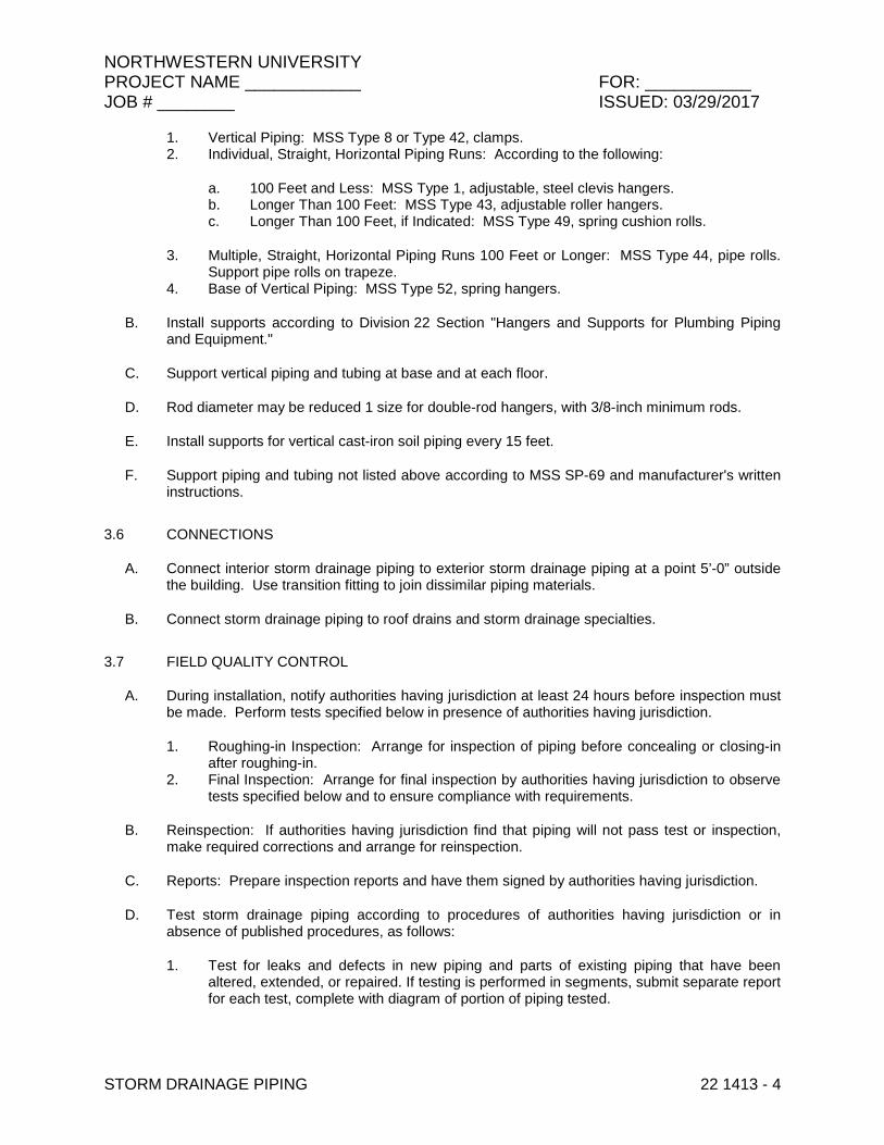
NORTHWESTERN UNIVERSITY PROJECT NAME ____________ FOR: ___________ JOB # ________ ISSUED: 03/29/2017
STORM DRAINAGE PIPING 22 1413 - 4
1. Vertical Piping: MSS Type 8 or Type 42, clamps. 2. Individual, Straight, Horizontal Piping Runs: According to the following:
a. 100 Feet and Less: MSS Type 1, adjustable, steel clevis hangers. b. Longer Than 100 Feet: MSS Type 43, adjustable roller hangers. c. Longer Than 100 Feet, if Indicated: MSS Type 49, spring cushion rolls.
3. Multiple, Straight, Horizontal Piping Runs 100 Feet or Longer: MSS Type 44, pipe rolls. Support pipe rolls on trapeze.
4. Base of Vertical Piping: MSS Type 52, spring hangers.
B. Install supports according to Division 22 Section "Hangers and Supports for Plumbing Piping and Equipment."
C. Support vertical piping and tubing at base and at each floor.
D. Rod diameter may be reduced 1 size for double-rod hangers, with 3/8-inch minimum rods.
E. Install supports for vertical cast-iron soil piping every 15 feet.
F. Support piping and tubing not listed above according to MSS SP-69 and manufacturer's written instructions.
3.6 CONNECTIONS
A. Connect interior storm drainage piping to exterior storm drainage piping at a point 5’-0” outside the building. Use transition fitting to join dissimilar piping materials.
B. Connect storm drainage piping to roof drains and storm drainage specialties.
3.7 FIELD QUALITY CONTROL
A. During installation, notify authorities having jurisdiction at least 24 hours before inspection must be made. Perform tests specified below in presence of authorities having jurisdiction.
1. Roughing-in Inspection: Arrange for inspection of piping before concealing or closing-in after roughing-in.
2. Final Inspection: Arrange for final inspection by authorities having jurisdiction to observe tests specified below and to ensure compliance with requirements.
B. Reinspection: If authorities having jurisdiction find that piping will not pass test or inspection, make required corrections and arrange for reinspection.
C. Reports: Prepare inspection reports and have them signed by authorities having jurisdiction.
D. Test storm drainage piping according to procedures of authorities having jurisdiction or in absence of published procedures, as follows:
1. Test for leaks and defects in new piping and parts of existing piping that have been altered, extended, or repaired. If testing is performed in segments, submit separate report for each test, complete with diagram of portion of piping tested.

NORTHWESTERN UNIVERSITY PROJECT NAME ____________ FOR: ___________ JOB # ________ ISSUED: 03/29/2017
STORM DRAINAGE PIPING 22 1413 - 5
2. Leave uncovered and unconcealed new, altered, extended, or replaced drainage piping until it has been tested and approved. Expose work that was covered or concealed before it was tested.
3. Test Procedure: Test drainage piping on completion of roughing in. Close openings in piping system and fill with water to point of overflow, but not less than 10-foot head of water. From 15 minutes before inspection starts to completion of inspection, water level must not drop. Inspect joints for leaks.
4. Repair leaks and defects with new materials and retest piping, or portion thereof, until satisfactory results are obtained.
5. Prepare reports for tests and required corrective action.
3.8 CLEANING
A. Clean interior of piping. Remove dirt and debris as work progresses.
B. Protect drains during remainder of construction period to avoid clogging with dirt and debris and to prevent damage from traffic and construction work.
C. Place plugs in ends of uncompleted piping at end of day and when work stops.
END OF SECTION 22 1413

NORTHWESTERN UNIVERSITY PROJECT NAME ____________ FOR: ___________ JOB # ________ ISSUED: 03/29/2017
STORM DRAINAGE PIPING SPECIALTIES 22 1423- 1
SECTION 22 1423 - STORM DRAINAGE PIPING SPECIALTIES
PART 1 - GENERAL
1.1 RELATED DOCUMENTS
A. Drawings and general provisions of the Contract, including General and Supplementary Conditions and Division 01 Specification Sections, apply to this Section.
1.2 SUMMARY
A. Section Includes:
1. Roof drains. 2. Deck drains 3. Miscellaneous storm drainage piping specialties. 4. Cleanouts. 5. Flashing materials.
1.3 SUBMITTALS
A. Product Data: For each type of product indicated.
1.4 QUALITY ASSURANCE
A. Drainage piping specialties shall bear label, stamp, or other markings of specified testing agency.
PART 2 - PRODUCTS
2.1 ROOF AND DECK DRAINS
A. Cast-Iron, Large-Sump, General-Purpose Roof Drains RD and ED:
1. Manufacturers: Subject to compliance with requirements, provide products by one of the following:
a. Josam Company. b. Smith, Jay R. Mfg. Co. c. Tyler Pipe; Wade Div. d. Zurn Plumbing Products Group; Specification Drainage Operation.
2. Standard: ASME A112.6.4, for general-purpose roof drains. 3. Body Material: Cast iron. 4. Dimension of Body: Nominal 15-inch diameter.
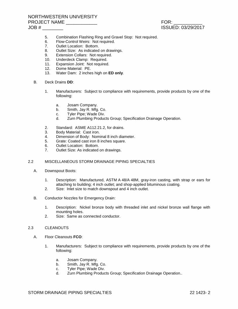
NORTHWESTERN UNIVERSITY PROJECT NAME ____________ FOR: ___________ JOB # ________ ISSUED: 03/29/2017
STORM DRAINAGE PIPING SPECIALTIES 22 1423- 2
5. Combination Flashing Ring and Gravel Stop: Not required. 6. Flow-Control Weirs: Not required. 7. Outlet Location: Bottom. 8. Outlet Size: As indicated on drawings. 9. Extension Collars: Not required. 10. Underdeck Clamp: Required. 11. Expansion Joint: Not required. 12. Dome Material: PE. 13. Water Dam: 2 inches high on ED only.
B. Deck Drains DD:
1. Manufacturers: Subject to compliance with requirements, provide products by one of the following:
a. Josam Company. b. Smith, Jay R. Mfg. Co. c. Tyler Pipe; Wade Div. d. Zurn Plumbing Products Group; Specification Drainage Operation.
2. Standard: ASME A112.21.2, for drains. 3. Body Material: Cast iron. 4. Dimension of Body: Nominal 8 inch diameter. 5. Grate: Coated cast iron 8 inches square. 6. Outlet Location: Bottom. 7. Outlet Size: As indicated on drawings.
2.2 MISCELLANEOUS STORM DRAINAGE PIPING SPECIALTIES
A. Downspout Boots:
1. Description: Manufactured, ASTM A 48/A 48M, gray-iron casting, with strap or ears for attaching to building; 4 inch outlet; and shop-applied bituminous coating.
2. Size: Inlet size to match downspout and 4 inch outlet.
B. Conductor Nozzles for Emergency Drain:
1. Description: Nickel bronze body with threaded inlet and nickel bronze wall flange with mounting holes.
2. Size: Same as connected conductor.
2.3 CLEANOUTS
A. Floor Cleanouts FCO:
1. Manufacturers: Subject to compliance with requirements, provide products by one of the following:
a. Josam Company. b. Smith, Jay R. Mfg. Co. c. Tyler Pipe; Wade Div. d. Zurn Plumbing Products Group; Specification Drainage Operation..
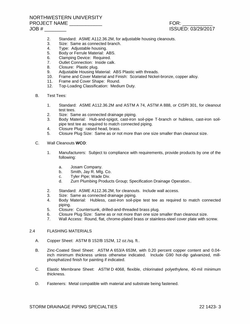
NORTHWESTERN UNIVERSITY PROJECT NAME ____________ FOR: ___________ JOB # ________ ISSUED: 03/29/2017
STORM DRAINAGE PIPING SPECIALTIES 22 1423- 3
2. Standard: ASME A112.36.2M, for adjustable housing cleanouts. 3. Size: Same as connected branch. 4. Type: Adjustable housing. 5. Body or Ferrule Material: ABS. 6. Clamping Device: Required. 7. Outlet Connection: Inside calk. 8. Closure: Plastic plug. 9. Adjustable Housing Material: ABS Plastic with threads. 10. Frame and Cover Material and Finish: Scoriated Nickel-bronze, copper alloy. 11. Frame and Cover Shape: Round. 12. Top-Loading Classification: Medium Duty.
B. Test Tees:
1. Standard: ASME A112.36.2M and ASTM A 74, ASTM A 888, or CISPI 301, for cleanout test tees.
2. Size: Same as connected drainage piping. 3. Body Material: Hub-and-spigot, cast-iron soil-pipe T-branch or hubless, cast-iron soil-
pipe test tee as required to match connected piping. 4. Closure Plug: raised head, brass. 5. Closure Plug Size: Same as or not more than one size smaller than cleanout size.
C. Wall Cleanouts WCO:
1. Manufacturers: Subject to compliance with requirements, provide products by one of the following:
a. Josam Company. b. Smith, Jay R. Mfg. Co. c. Tyler Pipe; Wade Div. d. Zurn Plumbing Products Group; Specification Drainage Operation..
2. Standard: ASME A112.36.2M, for cleanouts. Include wall access. 3. Size: Same as connected drainage piping. 4. Body Material: Hubless, cast-iron soil-pipe test tee as required to match connected
piping. 5. Closure: Countersunk, drilled-and-threaded brass plug. 6. Closure Plug Size: Same as or not more than one size smaller than cleanout size. 7. Wall Access: Round, flat, chrome-plated brass or stainless-steel cover plate with screw.
2.4 FLASHING MATERIALS
A. Copper Sheet: ASTM B 152/B 152M, 12 oz./sq. ft..
B. Zinc-Coated Steel Sheet: ASTM A 653/A 653M, with 0.20 percent copper content and 0.04-inch minimum thickness unless otherwise indicated. Include G90 hot-dip galvanized, mill-phosphatized finish for painting if indicated.
C. Elastic Membrane Sheet: ASTM D 4068, flexible, chlorinated polyethylene, 40-mil minimum thickness.
D. Fasteners: Metal compatible with material and substrate being fastened.
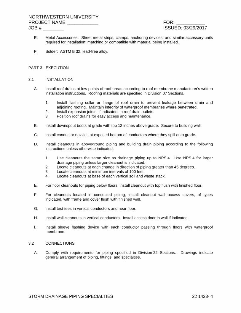
NORTHWESTERN UNIVERSITY PROJECT NAME ____________ FOR: ___________ JOB # ________ ISSUED: 03/29/2017
STORM DRAINAGE PIPING SPECIALTIES 22 1423- 4
E. Metal Accessories: Sheet metal strips, clamps, anchoring devices, and similar accessory units required for installation; matching or compatible with material being installed.
F. Solder: ASTM B 32, lead-free alloy.
PART 3 - EXECUTION
3.1 INSTALLATION
A. Install roof drains at low points of roof areas according to roof membrane manufacturer's written installation instructions. Roofing materials are specified in Division 07 Sections.
1. Install flashing collar or flange of roof drain to prevent leakage between drain and adjoining roofing. Maintain integrity of waterproof membranes where penetrated.
2. Install expansion joints, if indicated, in roof drain outlets. 3. Position roof drains for easy access and maintenance.
B. Install downspout boots at grade with top 12 inches above grade. Secure to building wall.
C. Install conductor nozzles at exposed bottom of conductors where they spill onto grade.
D. Install cleanouts in aboveground piping and building drain piping according to the following instructions unless otherwise indicated:
1. Use cleanouts the same size as drainage piping up to NPS 4. Use NPS 4 for larger drainage piping unless larger cleanout is indicated.
2. Locate cleanouts at each change in direction of piping greater than 45 degrees. 3. Locate cleanouts at minimum intervals of 100 feet. 4. Locate cleanouts at base of each vertical soil and waste stack.
E. For floor cleanouts for piping below floors, install cleanout with top flush with finished floor.
F. For cleanouts located in concealed piping, install cleanout wall access covers, of types indicated, with frame and cover flush with finished wall.
G. Install test tees in vertical conductors and near floor.
H. Install wall cleanouts in vertical conductors. Install access door in wall if indicated.
I. Install sleeve flashing device with each conductor passing through floors with waterproof membrane.
3.2 CONNECTIONS
A. Comply with requirements for piping specified in Division 22 Sections. Drawings indicate general arrangement of piping, fittings, and specialties.
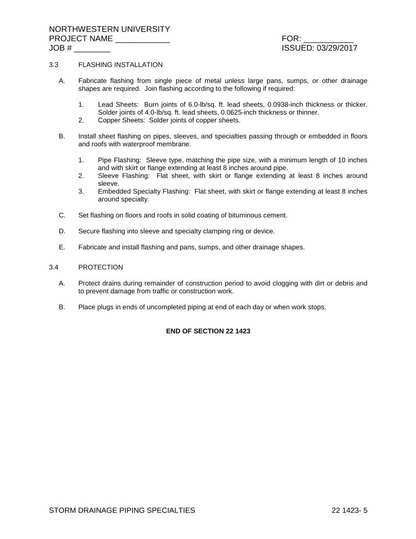
NORTHWESTERN UNIVERSITY PROJECT NAME ____________ FOR: ___________ JOB # ________ ISSUED: 03/29/2017
STORM DRAINAGE PIPING SPECIALTIES 22 1423- 5
3.3 FLASHING INSTALLATION
A. Fabricate flashing from single piece of metal unless large pans, sumps, or other drainage shapes are required. Join flashing according to the following if required:
1. Lead Sheets: Burn joints of 6.0-lb/sq. ft. lead sheets, 0.0938-inch thickness or thicker. Solder joints of 4.0-lb/sq. ft. lead sheets, 0.0625-inch thickness or thinner.
2. Copper Sheets: Solder joints of copper sheets.
B. Install sheet flashing on pipes, sleeves, and specialties passing through or embedded in floors and roofs with waterproof membrane.
1. Pipe Flashing: Sleeve type, matching the pipe size, with a minimum length of 10 inches and with skirt or flange extending at least 8 inches around pipe.
2. Sleeve Flashing: Flat sheet, with skirt or flange extending at least 8 inches around sleeve.
3. Embedded Specialty Flashing: Flat sheet, with skirt or flange extending at least 8 inches around specialty.
C. Set flashing on floors and roofs in solid coating of bituminous cement.
D. Secure flashing into sleeve and specialty clamping ring or device.
E. Fabricate and install flashing and pans, sumps, and other drainage shapes.
3.4 PROTECTION
A. Protect drains during remainder of construction period to avoid clogging with dirt or debris and to prevent damage from traffic or construction work.
B. Place plugs in ends of uncompleted piping at end of each day or when work stops.
END OF SECTION 22 1423

NORTHWESTERN UNIVERSITY PROJECT NAME ____________ FOR: ___________ JOB # ________ ISSUED: 03/29/2017
STORM DRAINAGE PIPING SPECIALTIES 22 1423- 6
THIS PAGE IS INTENTIONALLY BLANK

NORTHWESTERN UNIVERSITY PROJECT NAME ____________ FOR: ___________ JOB # ________ ISSUED: 03/29/2017
NATURAL GAS PIPING 22 1616 - 1
SECTION 22 1616 – NATURAL GAS PIPING
PART 1 - GENERAL
1.1 RELATED DOCUMENTS
A. Drawings and general provisions of the Contract, including General and Supplementary Conditions and Division 01 Specification Sections, apply to this Section.
B. Specifications throughout all Divisions of the Project Manual are directly applicable to this Section, and this Section is directly applicable to them.
1.2 SUMMARY
A. Section Includes:
1. Aboveground pipe and fittings from meter and main regulator to building equipment. 2. Piping specialties and Art Room gas outlet. 3. Piping and tubing joining materials. 4. Valves. 5. Pressure regulators.
1.3 REFERENCE STANDARDS
A. The latest published edition of a reference shall be applicable to this Project unless identified by a specific edition date.
B. All reference amendments adopted prior to the effective date of this Contract shall be applicable to this Project.
C. All materials, installation and workmanship shall comply with the applicable requirements and standards addressed within the following references:
1. 2009 Edition of the International Fuel Gas Code. 2. Latest edition of NFPA 54.
1.4 PERFORMANCE REQUIREMENTS
A. Minimum Operating-Pressure Ratings:
1. Piping and Valves: 100 psig minimum unless otherwise indicated. 2. Service Regulators: 100 psig minimum unless otherwise indicated.
B. Natural-Gas System Pressure within Buildings: 2.0 psig or less

NORTHWESTERN UNIVERSITY PROJECT NAME ____________ FOR: ___________ JOB # ________ ISSUED: 03/29/2017
NATURAL GAS PIPING 22 1616 - 2
1.5 SUBMITTALS
A. Product Data: For each type of product indicated.
B. Welding certificates.
C. Field quality-control reports.
D. Operation and maintenance data.
1.6 QUALITY ASSURANCE
A. Steel Support Welding Qualifications: Qualify procedures and personnel according to AWS D1.1/D1.1M, "Structural Welding Code - Steel."
B. Pipe Welding Qualifications: Qualify procedures and operators according to ASME Boiler and Pressure Vessel Code.
C. Electrical Components, Devices, and Accessories: Listed and labeled as defined in NFPA 70, by a qualified testing agency, and marked for intended location and application.
D. Manufacturer Qualifications: Company specializing in manufacturing the Products specified in this section with minimum three (3) years documented experience.
E. Installer Qualifications: Company specializing in performing the Work of this Section with minimum three (3) years documented experience.
F. Conformance to National Fuel Gas Code.
G. Material and installation requirements shall follow NFPA 54, state and local gas company codes.
H. Conformance to ANSI B31.
I. Gas regulators shall be AGA rated.
1.7 DELIVERY, STORAGE and HANDLING
A. Accept valves on Site in shipping containers with labeling in place, inspect for damage and store with a minimum of handling. Store plastic piping under cover out of direct sunlight. Do not store materials directly on the ground.
B. Protect piping systems from entry of foreign materials by temporary covers, completing sections of the work and isolating parts of completed system.

NORTHWESTERN UNIVERSITY PROJECT NAME ____________ FOR: ___________ JOB # ________ ISSUED: 03/29/2017
NATURAL GAS PIPING 22 1616 - 3
PART 2 - PRODUCTS
2.1 GENERAL
A. All materials shall meet or exceed all applicable referenced standards, federal, state and local requirements, and conform to codes and ordinances of authorities having jurisdiction.
2.2 PIPES, TUBES, AND FITTINGS
A. Steel Pipe: ASTM A 53/A 53M, black steel, Schedule 40, Type E or S, Grade B.
1. Malleable-Iron Threaded Fittings: ASME B16.3, Class 150, standard pattern. 2. Wrought-Steel Welding Fittings: ASTM A 234/A 234M for butt welding and socket
welding. 3. Unions: ASME B16.39, Class 150, malleable iron with brass-to-iron seat, ground joint,
and threaded ends.
2.3 JOINING MATERIALS
A. Joint Compound and Tape: Suitable for natural gas.
B. Welding Filler Metals: Comply with AWS D10.12/D10.12M for welding materials appropriate for wall thickness and chemical analysis of steel pipe being welded.
C. Brazing Filler Metals: Alloy with melting point greater than 1000 deg F complying with AWS A5.8/A5.8M. Brazing alloys containing more than 0.05 percent phosphorus are prohibited.
2.4 GAS VALVES
A. All valves shall be designed, manufactured and approved for natural gas service.
B. Line Shut-off Valves sizes 2 inches and smaller shall be iron body lubricated plug valve conforming to ASTM-A-126, U.L. Listed and A.G.A. Approved for natural gas service with threaded ends, wrench operation, rated for 200 WOG service pressure and –20 to 200 degrees F., manufactured by Nordstrom Model 142 or equal by Resun or McDonald, A. Y. Mfg. Co.
C. Line Shut-off Valves sizes 2½ inches and larger shall be iron body lubricated plug valve conforming to ASTM-A-126, U.L. Listed and A.G.A. Approved for natural gas service with flanged ends, wrench operation, rated for 200 WOG service pressure and –20 to 200 degrees F., manufactured by Nordstrom Model 143 or equal by Resun or McDonald, A. Y. Mfg. Co.
D. Appliance/Equipment Shut-off Valves at local connections sizes 2 inches and smaller shall be bronze body, full port ball or butterfly type, U.L. Listed and A.G.A. Approved for natural gas service with threaded ends, quarter turn lever handle operation, rated for 175 W.O.G. service pressure and 30 to 275 degrees F., manufactured by Nibco Model T585-70-UL or equal by Milwaukee or Apollo.
E. Manual Emergency Shut-off Valves sizes 2 inches and smaller shall be bronze body, full port ball or butterfly type, U.L. Listed and A.G.A. Approved for natural gas service with threaded ends, quarter turn lever handle operation, rated for 175 W.O.G. service pressure and 30 to 275 degrees F., manufactured by Nibco Model T585-70-UL or equal by Milwaukee or Apollo.
NORTHWESTERN UNIVERSITY PROJECT NAME ____________ FOR: ___________ JOB # ________ ISSUED: 03/29/2017
NATURAL GAS PIPING 22 1616 - 4
F. Automatic Emergency Shut-off Valves shall be U.L. Listed F.M. Approved for natural gas service, 2-way electrically tripped solenoid type; fail safe closed; manual reset; Type 1 solenoid enclosure; NBR seals and disc; stainless steel core tube and springs; copper coil; manufactured by ASCO Red Hat Series 8044 or equal by Honeywell or Jefferson.
2.5 PRESSURE REGULATORS
A. General Requirements:
1. Single stage and suitable for natural gas. 2. Steel jacket and corrosion-resistant components. 3. Elevation compensator. 4. End Connections: Threaded for regulators NPS 2 and smaller.
B. Appliance Pressure Regulators: Comply with ANSI Z21.18.
1. Manufacturers: Subject to compliance with requirements, provide products by one of the following:
a. Eaton Corporation; Controls Div. b. Harper Wyman Co. c. Maxitrol Company. d. Itron
2. Body and Diaphragm Case: Die-cast aluminum. 3. Springs: Zinc-plated steel; interchangeable. 4. Diaphragm Plate: Zinc-plated steel. 5. Seat Disc: Nitrile rubber. 6. Seal Plug: Ultraviolet-stabilized, mineral-filled nylon. 7. Factory-Applied Finish: Minimum three-layer polyester and polyurethane paint finish. 8. Atmospheric Vent: Factory installed. 9. Maximum Inlet Pressure: 2 psig
C. Line Pressure Regulators: Comply with ANSI Z21.80.
1. Manufacturers: Subject to compliance with requirements, provide products by one of the following:
a. Belgas b. Eaton Corporation; Controls Div. c. Harper Wyman Co. d. Maxitrol Company.
2. Body and Diaphragm Case: Cast iron or die-cast aluminum. 3. Springs: Zinc-plated steel; interchangeable. 4. Diaphragm Plate: Zinc-plated steel. 5. Seat Disc: Nitrile rubber resistant to gas impurities, abrasion, and deformation at the
valve port. 6. Orifice: Aluminum; interchangeable. 7. Seal Plug: Ultraviolet-stabilized, mineral-filled nylon. 8. Single-port, self-contained regulator with orifice no larger than required at maximum
pressure inlet, and no pressure sensing piping external to the regulator.

NORTHWESTERN UNIVERSITY PROJECT NAME ____________ FOR: ___________ JOB # ________ ISSUED: 03/29/2017
NATURAL GAS PIPING 22 1616 - 5
9. Pressure regulator shall maintain discharge pressure setting downstream, and not exceed 120 percent of design discharge pressure at shutoff.
10. Overpressure Protection Device: Factory mounted on pressure regulator. 11. Atmospheric Vent: Factory- or field-installed, stainless-steel screen in opening if not
connected to vent piping. 12. Maximum Inlet Pressure: 5 psig 13. Suitable for outdoor use to minus 40 F ambient temperature.
2.6 DIELECTRIC UNIONS
A. Dielectric Unions:
1. Manufacturers: Subject to compliance with requirements, provide products by one of the following:
a. Hart Industries International, Inc. b. McDonald, A. Y. Mfg. Co. c. Watts Regulator Co.; a division of Watts Water Technologies, Inc. d. Wilkins; a Zurn company.
2. Description:
a. Standard: ASSE 1079. b. Pressure Rating: 125 psig at 180 deg F. c. End Connections: Solder-joint copper alloy and threaded ferrous.
PART 3 - EXECUTION
3.1 INDOOR PIPING INSTALLATION
A. Comply with NFPA 54 for installation and purging of natural-gas piping.
B. Drawing plans, schematics, and diagrams indicate general location and arrangement of piping systems. Indicated locations and arrangements are used to size pipe and calculate friction loss, expansion, and other design considerations. Install piping as indicated unless deviations to layout are approved on Coordination Drawings.
C. Arrange for pipe spaces, chases, slots, sleeves, and openings in building structure during progress of construction, to allow for mechanical installations.
D. Install piping in concealed locations (as allowed per code) unless otherwise indicated and except in equipment rooms and service areas.
E. Install piping indicated to be exposed and piping in equipment rooms and service areas at right angles or parallel to building walls. Diagonal runs are prohibited unless specifically indicated otherwise.
F. Install piping above accessible ceilings to allow sufficient space for ceiling panel removal.
G. Locate valves for easy access.
NORTHWESTERN UNIVERSITY PROJECT NAME ____________ FOR: ___________ JOB # ________ ISSUED: 03/29/2017
NATURAL GAS PIPING 22 1616 - 6
H. Install piping free of sags and bends.
I. Install fittings for changes in direction and branch connections.
J. Verify final equipment locations for roughing-in.
K. Comply with requirements in Sections specifying gas-fired appliances and equipment for roughing-in requirements.
L. Drips and Sediment Traps: Install drips at points where condensate may collect, including service-meter outlets. Locate where accessible to permit cleaning and emptying. Do not install where condensate is subject to freezing.
1. Construct drips and sediment traps using tee fitting with bottom outlet plugged or capped. Use nipple a minimum length of 3 pipe diameters, but not less than 3 inches long and same size as connected pipe. Install with space below bottom of drip to remove plug or cap.
M. Extend relief vent connections for service regulators, line regulators, and overpressure protection devices to outdoors and terminate with weatherproof vent cap.
N. Conceal pipe installations in walls, pipe spaces, utility spaces, above ceilings, unless indicated to be exposed to view. Pipe concealed in walls and partitions shall be installed in an approved chase or casing. Piping in concealed locations shall not have unions, tubing fittings, right and left couplings, bushings, compression couplings, nor swing joints made by combinations of fittings. Tubing joined by brazing is allowed, as are fittings listed for use in concealed locations.
O. Use eccentric reducer fittings to make reductions in pipe sizes. Install fittings with level side down.
P. Connect branch piping from top or side of horizontal piping.
Q. Install unions in pipes NPS 2 and smaller, adjacent to each valve, at final connection to each piece of equipment.
R. Do not use natural-gas piping as grounding electrode.
S. Install strainer on inlet of each line-pressure regulator and automatic or electrically operated valve.
T. Install pressure gage downstream from each line regulator. Pressure gages are specified in Division 23 Section "Meters and Gages for HVAC Piping."
U. Install sleeves for piping penetrations of walls, ceilings, and floors, concrete walls or slabs. Comply with requirements for sleeves specified in Division 23 Section "Common Work Results for HVAC.”
V. Install escutcheons for piping penetrations of walls, ceilings, and floors. Comply with requirements for escutcheons specified in Division 23 Section "Common Work Results for HVAC."
NORTHWESTERN UNIVERSITY PROJECT NAME ____________ FOR: ___________ JOB # ________ ISSUED: 03/29/2017
NATURAL GAS PIPING 22 1616 - 7
3.2 VALVE INSTALLATION
A. Install manual gas shutoff valve for each gas appliance.
B. Install regulators and overpressure protection devices with maintenance access space adequate for servicing and testing.
C. Install cooking appliance shunt trip valve per valve manufacturer's instructions and in coordination with kitchen equipment contractor.
3.3 PIPING JOINT CONSTRUCTION
A. Ream ends of pipes and tubes and remove burrs.
B. Remove scale, slag, dirt, and debris from inside and outside of pipe and fittings before assembly.
C. Threaded Joints:
1. Thread pipe with tapered pipe threads complying with ASME B1.20.1. 2. Cut threads full and clean using sharp dies. 3. Ream threaded pipe ends to remove burrs and restore full inside diameter of pipe. 4. Apply appropriate tape or thread compound to external pipe threads unless dryseal
threading is specified. 5. Damaged Threads: Do not use pipe or pipe fittings with threads that are corroded or
damaged. Do not use pipe sections that have cracked or open welds.
D. Welded Joints:
1. Construct joints according to AWS D10.12/D10.12M, using qualified processes and welding operators.
2. Bevel plain ends of steel pipe. 3. Patch factory-applied protective coating as recommended by manufacturer at field welds
and where damage to coating occurs during construction.
3.4 HANGER AND SUPPORT INSTALLATION
A. Comply with requirements for pipe hangers and supports specified in Division 22 Section "Hangers and Supports for Plumbing Piping and Equipment."
3.5 CONNECTIONS
A. Connect to utility's gas main after meter and regulator.
B. Install natural-gas piping electrically continuous, and bonded to gas appliance equipment grounding conductor of the circuit powering the appliance according to NFPA 70.
C. Install piping adjacent to appliances to allow service and maintenance of appliances.
D. Connect piping to appliances using manual gas shutoff valves and unions. Install valve within 72 inches of each gas-fired appliance and equipment. Install union between valve and appliances or equipment.

NORTHWESTERN UNIVERSITY PROJECT NAME ____________ FOR: ___________ JOB # ________ ISSUED: 03/29/2017
NATURAL GAS PIPING 22 1616 - 8
E. Sediment Traps: Install tee fitting with capped nipple in bottom to form drip, as close as practical to inlet of each appliance.
3.6 LABELING AND IDENTIFYING
A. Comply with requirements in Division 23 Section "Identification for HVAC Piping and Equipment" for piping and valve identification.
3.7 FIELD QUALITY CONTROL
A. Test, inspect, and purge natural gas according to NFPA 54 and authorities having jurisdiction.
B. Natural-gas piping will be considered defective if it does not pass tests and inspections.
C. Prepare test and inspection reports.
3.8 INDOOR PIPING SCHEDULE
A. Aboveground, branch & distribution piping NPS 2 and smaller shall the following:
1. Steel pipe with malleable-iron fittings and threaded joints. 2. EXCEPTIONS:
a. All exposed piping 1½ inches and smaller located within areas utilized as return air plenums shall have welded joints with Schedule 40 socket welded forged steel fittings conforming to ASME B16.11.
b. All exposed piping 1½ inches and smaller serving laboratories from main natural gas riser to each emergency shut-off valve shall have welded joints with Schedule 40 socket welded forged steel fittings conforming to ASME B16.11.
B. Aboveground, branch & distribution piping larger than NPS 2 shall the following:
1. Steel pipe with wrought-steel fittings and welded joints.
3.9 OUTDOOR PIPING SCHEDULE
A. Aboveground, NPS 2 and smaller shall be the following:
1. Steel pipe with malleable-iron fittings and threaded joints.
B. Aboveground, larger than NPS 2 shall the following:
1. Steel pipe with wrought-steel fittings and welded joints.
3.10 PAINTING
A. Comply with requirements in Section 099100 Painting for painting exterior natural-gas piping (ferrous metal).
B. Paint exposed, exterior metal piping, valves, regulators, and piping specialties, except components, with factory-applied paint or protective coating.
NORTHWESTERN UNIVERSITY PROJECT NAME ____________ FOR: ___________ JOB # ________ ISSUED: 03/29/2017
NATURAL GAS PIPING 22 1616 - 9
1. Gloss finish. 2. Color - Yellow.
C. Damage and Touchup: Repair marred and damaged factory-applied finishes with materials and by procedures to match original factory finish.
END OF SECTION 22 1616

NORTHWESTERN UNIVERSITY PROJECT NAME ____________ FOR: ___________ JOB # ________ ISSUED: 03/29/2017
NATURAL GAS PIPING 22 1616 - 10
THIS PAGE IS INTENTIONALLY BLANK
NORTHWESTERN UNIVERSITY PROJECT NAME ____________ FOR: ___________ JOB # ________ ISSUED: 03/29/2017
DOMESTIC WATER SOFTENERS 22 3100 - 1
SECTION 22 3100 – DOMESTIC WATER SOFTENERS
PART 1 - GENERAL
1.1 SUMMARY
A. Section Includes:
1. Commercial water softeners. 2. Chemicals. 3. Water-testing sets.
1.2 ACTION SUBMITTALS
A. Product Data: For each type of product indicated.
1. Include construction details, material descriptions, dimensions of individual components and profiles, and finishes for water softeners.
2. Include rated capacities, operating characteristics, electrical characteristics, and furnished specialties and accessories.
3. Wiring Diagrams: For power, signal, and control wiring.
1.3 CLOSEOUT SUBMITTALS
A. Field quality-control reports.
B. Warranty.
C. Operation and maintenance data.
1.4 MAINTENANCE MATERIAL SUBMITTALS
A. Furnish extra materials that match products installed and that are packaged with protective covering for storage and identified with labels describing contents.
1. Salt for Brine Tanks: Furnish in same form as and at least four times original load. 2. Store salt on raised platform where directed by Owner. Do not store in contact with
concrete floor.
1.5 QUALITY ASSURANCE
A. Electrical Components, Devices, and Accessories: Listed and labeled as defined in NFPA 70, by a qualified testing agency, and marked for intended application.
B. ASME Compliance for Steel Tanks: Fabricate and label mineral tanks to comply with ASME Boiler and Pressure Vessel Code: Section VIII, Division 1, where indicated.

NORTHWESTERN UNIVERSITY PROJECT NAME ____________ FOR: ___________ JOB # ________ ISSUED: 03/29/2017
DOMESTIC WATER SOFTENERS 22 3100 - 2
C. UL Compliance: Fabricate and label water softeners to comply with UL 979, "Water Treatment Appliances."
1.6 WARRANTY
A. Special Warranty: Manufacturer's standard form in which manufacturer agrees to repair or replace components of water softeners that fail in materials or workmanship within specified warranty period.
1. Commercial Water Softeners, Warranty Period: From date of Substantial Completion.
a. Mineral & Brine Tanks: Five years. b. System and Control Valve: One year.
B. The universal warranty start date is defined in the front end documents.
PART 2 - PRODUCTS
2.1 COMMERCIAL WATER SOFTENERS
A. Basis-of-Design Product: Subject to compliance with requirements, provide product indicated on Drawings or comparable product by one of the following:
1. Culligan International Company. 2. Ecodyne Water Treatment, Inc. 3. Kinetico Incorporated. 4. Marley 5. WaterSoft; a division of Amtrol, Inc.
B. Description: Factory-assembled, pressure-type water softener.
1. Furnish and install a water softener to provide a zero soft water effluent as determined by an ASTM standard soap test method, when operated in accordance with operating instructions. Each unit shall be designed to provide X grains per tank maximum capacity of hardness reduction between regenerations at a maximum salt dosage of X lbs. salt. Each unit shall be capable of a continuous flow rate of X GPM with a pressure drop of 15 psi and a peak flow rate of X GPM with a pressure drop of 25 psi.
2. The softener vessel(s) shall be designed for a working pressure of 150 psi and a temperature of 120 degrees F. A minimum freeboard volume of 50% shall be provided to assure adequate bed expansion during backwash. Vessel(s) shall be manufactured of fiberglass reinforced polyester (FRP). The exterior side shall be reinforced by a continuous roving glass filament overwrap of the same color as the vessel(s) shell. The vessel(s) shall be supported by a molded polypropylene structural base.
3. The backwash distributor and soft water collector shall be of the hub-radial design and shall require only assembly of the riser pipe upon installation. The radials shall be designed with a higher density of slots at the outer ends to provide adequate distribution and collection of water away from the center of the tank. Internal piping material shall be constructed of PVC and/or ABS plastic. Systems shall have a single point distributor.
4. The softener shall be provided with X cubic feet of high-capacity, non-phenolic resin per vessel(s) having a minimum exchange of capacity of X grains per cubic foot when regenerated with X lbs. of salt per cubic foot. The media shall be solid, of the proper
NORTHWESTERN UNIVERSITY PROJECT NAME ____________ FOR: ___________ JOB # ________ ISSUED: 03/29/2017
DOMESTIC WATER SOFTENERS 22 3100 - 3
particle size (not more than 4% through 40 mesh U.S. standard screen, wet screening) and shall contain no plates, shells, agglomerates or other shapes which might interfere with the normal function of the water softener.
5. The combination salt storage and brine measuring tank with cover shall be sized to hold X lbs. of salt. The tank shall be of rotationally molded rigid polyethylene. The brine tank shall be equipped with an elevated salt plate for the collection of brine and shall have a chamber to house a brine valve assembly. The brine valve assembly shall include an automatic air eliminator and safety float shut-off valve. It shall open automatically, to educt brine, close to prevent the entrance of air after the brine has been drawn, and permit refill of the tank with the correct amount of water. Brine dosage shall be controlled by the softener control valve through an adjustment on the clock timer. The system shall be designed to allow proper refilling regardless of the salt level in the tank.
6. Controls: Fully automatic; factory wired and factory mounted on unit.
a. Adjustable duration of various regeneration steps. b. Push-button start and complete manual operation. c. Twin Alternating Control – The regeneration shall be controlled by a mechanically
operated automatic reset water meter installed in the common soft water effluent line. Softeners shall be regenerated based on total gallons through the meter. An alternator shall be supplied to allow only one unit to be in regeneration or standby at a time while the other unit is in-service. This system shall provide a continuous supply of soft water. Indicating lights shall be provided to show which unit is in-service and which one is regenerating
d. Sequence of Operation: Multiport pilot-control valve automatically pressure-actuates main operating valve through steps of regeneration and return to service.
e. Pointer on pilot-control valve shall indicate cycle of operation. f. Includes means of manual operation of pilot-control valve if power fails.
7. Main Operating Valves: Industrial, automatic, multiport, diaphragm type with the following features:
a. X inch inlet and outlet connections b. Constructed of lead-free brass. c. Mechanically actuated, four position type to accomplish the regeneration steps of
backwash, brine draw / slow rinse, fast rinse and brine tank refill. d. The valve shall contain a fixed orifice eductor nozzle and self-adjusting backwash
flow control. e. Slow opening and closing, non-slam operation. f. Diaphragm guiding on full perimeter from fully open to fully closed. g. Self-adjusting, internal, automatic brine injector that draws brine and rinses at
constant rate independent of pressure. h. Sampling cocks for soft water. i. Special tools are not required for service.
8. Flow Control: Automatic, to control backwash and flush rates over wide variations in operating pressure; does not require field adjustments.
a. Demand-Initiated Control: Each mineral tank of twin mineral-tank unit is equipped with automatic-reset-head water meter that electrically activates cycle controllers to initiate regeneration at preset total in gallons. Head automatically resets to preset total in gallons for next service run. Electrical lockout prevents simultaneous regeneration of both tanks.

NORTHWESTERN UNIVERSITY PROJECT NAME ____________ FOR: ___________ JOB # ________ ISSUED: 03/29/2017
DOMESTIC WATER SOFTENERS 22 3100 - 4
9. Factory-Installed Accessories:
a. Piping, valves, tubing, and drains. b. Sampling cocks. c. Main-operating-valve position indicators. d. Water meters.
C. Capacities and Characteristics:
1. Water Analysis:
a. Hardness: X grains/gal. b. Inlet Water Pressure: X psig c. Water Temperature: X deg F
2. Continuous Service Flow Rate: X gpm at 15-psig pressure drop. 3. Peak Service Flow Rate: X gpm at 25-psig pressure drop. 4. Water Meter Size: X” 5. Manifold Pipe Size: X” 6. Water Consumption: X gal./day 7. Number of Mineral Tanks: Two. 8. Mineral Quantity, Each Tank: X cu. ft. 9. Mineral Exchange Capacity: X grains per cubic foot 10. Electrical Characteristics: 24 Volt 11. Salt Capacity: X lbs
2.2 CHEMICALS
A. Mineral: High-capacity, sulfonated-polystyrene, ion-exchange resin that is stable over entire pH range with good resistance to bead fracture from attrition or shock.
1. Exchange Capacity: X grains/cu. ft. of calcium carbonate of resin when regenerated with X lb of salt.
B. Salt for Brine Tanks: High-purity sodium chloride, free of dirt and foreign material. Rock and granulated forms are unacceptable.
2.3 WATER-TESTING SETS
A. Description: Manufacturer's standard water-hardness testing apparatus and chemicals with testing procedure instructions. Include metal container suitable for wall mounting.
PART 3 - EXECUTION
3.1 WATER SOFTENER INSTALLATION
A. Equipment Mounting:
1. Install commercial water softeners on cast-in-place concrete equipment base(s). Comply with requirements for equipment bases and foundations specified in Section 033000 "Cast-in-Place Concrete."
NORTHWESTERN UNIVERSITY PROJECT NAME ____________ FOR: ___________ JOB # ________ ISSUED: 03/29/2017
DOMESTIC WATER SOFTENERS 22 3100 - 5
B. Install brine lines and fittings furnished by equipment manufacturer but not specified to be factory installed.
C. Prepare mineral-tank distribution system and underbed for minerals and place specified mineral into mineral tanks.
D. Install water-testing sets mounted on wall, unless otherwise indicated, and near water softeners.
E. Identify system components. Comply with requirements for identification specified in Section 220553 "Identification for Plumbing Piping and Equipment."
3.2 CONNECTIONS
A. Comply with requirements for piping specified in Section 221116 "Domestic Water Piping." Drawings indicate general arrangement of piping, fittings, and specialties.
B. Where piping is installed adjacent to equipment, allow space for service and maintenance of equipment.
C. Install shutoff valves on raw-water inlet and soft-water outlet piping of each mineral tank.
1. Metal general-duty valves are specified in Section 220523 "General-Duty Valves for Plumbing Piping."
2. Exception: Water softeners with factory-installed shutoff valves at locations indicated.
D. Install pressure gages on raw-water inlet and soft-water outlet piping of each mineral tank. Pressure gages are specified in Section 220519 "Meters and Gages for Plumbing Piping."
1. Exception: Water softeners with factory-installed pressure gages at locations indicated.
E. Install valved bypass in water piping around water softeners.
1. Metal general-duty valves are specified in Section 220523 "General-Duty Valves for Plumbing Piping."
2. Water piping is specified in Section 221116 "Domestic Water Piping."
F. Install drains as indirect wastes to spill into open drains or over floor drains.
3.3 FIELD QUALITY CONTROL
A. Tests and Inspections:
1. Leak Test: After installation, charge system and test for leaks. Repair leaks and retest until no leaks exist.
2. Operational Test: After electrical circuitry has been energized, start units to confirm proper unit operation.
3. Test and adjust controls and safeties. Replace damaged and malfunctioning controls and equipment.
B. Prepare test and inspection reports.

NORTHWESTERN UNIVERSITY PROJECT NAME ____________ FOR: ___________ JOB # ________ ISSUED: 03/29/2017
DOMESTIC WATER SOFTENERS 22 3100 - 6
3.4 STARTUP SERVICE
A. Engage a factory-authorized service representative to perform startup service.
1. Complete installation and startup checks according to manufacturer's written instructions.
B. Add water to brine tanks and fill with the following form of salt:
1. Commercial Water Softeners: The media shall be solid, of the proper particle size (not more than 4% through 40 mesh U.S. standard screen, wet screening) and shall contain no plates, shells, agglomerates or other shapes which might interfere with the normal function of the water softener.
C. Sample water softener effluent after startup and at three consecutive seven-day intervals (total of four samples), and prepare certified test reports for required water performance characteristics. Comply with the following:
1. ASTM D 859, "Test Method for Silica in Water." 2. ASTM D 1067, "Test Methods for Acidity or Alkalinity of Water." 3. ASTM D 1068, "Test Methods for Iron in Water." 4. ASTM D 1126, "Test Method for Hardness in Water." 5. ASTM D 1129, "Terminology Relating to Water." 6. ASTM D 3370, "Practices for Sampling Water from Closed Conduits."
3.5 DEMONSTRATION
A. Train Owner's maintenance personnel to adjust, operate, and maintain water softeners.
END OF SECTION 22 3100

NORTHWESTERN UNIVERSITY PROJECT NAME ____________ FOR: ___________ JOB # ________ ISSUED: 03/29/2017
ELECTRIC, DOMESTIC WATER HEATERS 22 3300 - 1
SECTION 22 3300 - ELECTRIC, DOMESTIC WATER HEATERS
PART 1 - GENERAL
1.1 RELATED DOCUMENTS
A. Drawings and general provisions of the Contract, including General and Supplementary Conditions and Division 01 Specification Sections, apply to this Section.
1.2 SUMMARY
A. Section Includes:
1. Commercial, electric, storage, domestic water heaters. 2. Thermostat-control, electric, tank-less, domestic water heaters. 3. Domestic-water heater accessories.
1.3 SUBMITTALS
A. Product Data: For each type and size of domestic-water heater indicated.
B. LEED Submittal:
1. Product Data for Prerequisite EA 2: Documentation indicating that units comply with ASHRAE/IESNA 90.1, Section 7, "Service Water Heating."
C. Shop Drawings:
1. Wiring Diagrams: For power, signal, and control wiring.
D. Domestic Water Heater Labeling: Certified and labeled by testing agency acceptable to authorities having jurisdiction.
E. Source quality-control reports.
F. Field quality-control reports.
G. Operation and maintenance data.
H. Warranty: Sample of special warranty.
1.4 QUALITY ASSURANCE
A. Electrical Components, Devices, and Accessories: Listed and labeled as defined in NFPA 70, by a qualified testing agency, and marked for intended location and application.
B. ASHRAE/IESNA 90.1 Compliance: Applicable requirements in ASHRAE/IESNA 90.1.
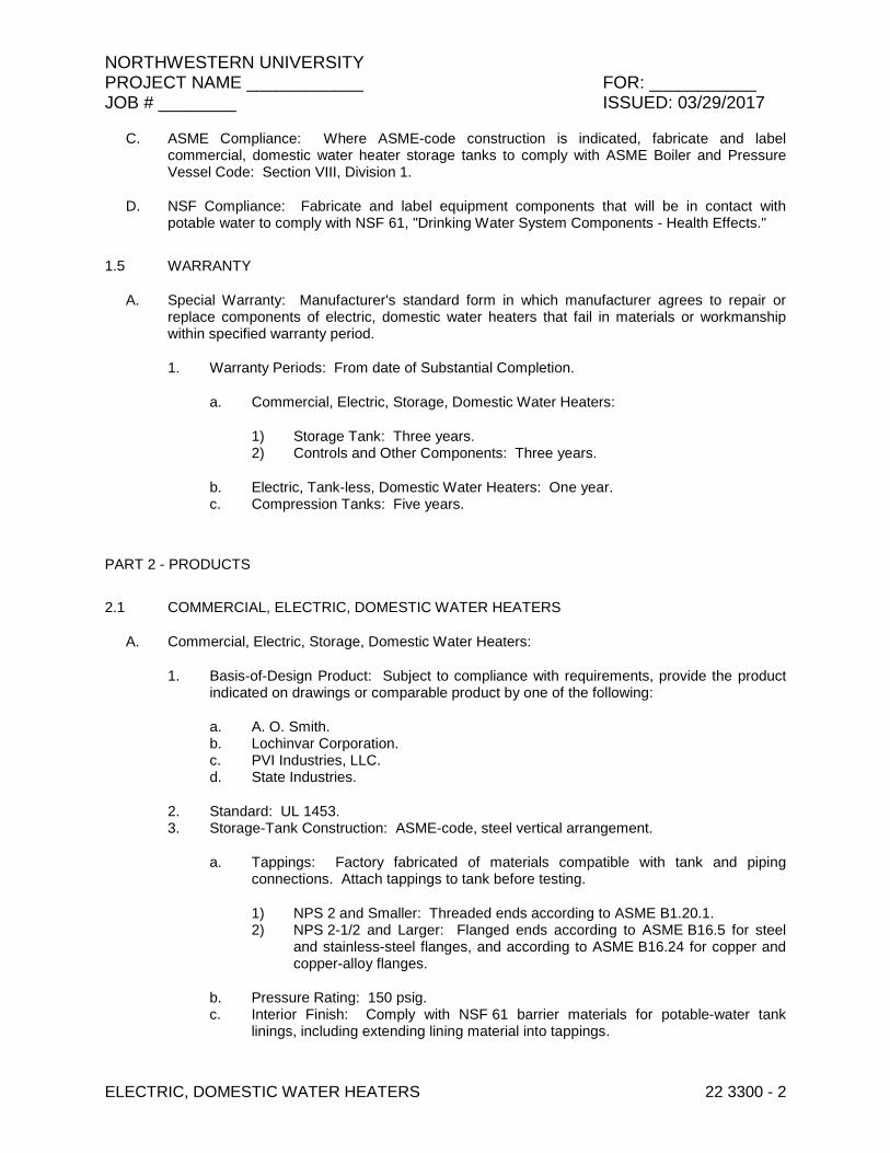
NORTHWESTERN UNIVERSITY PROJECT NAME ____________ FOR: ___________ JOB # ________ ISSUED: 03/29/2017
ELECTRIC, DOMESTIC WATER HEATERS 22 3300 - 2
C. ASME Compliance: Where ASME-code construction is indicated, fabricate and label commercial, domestic water heater storage tanks to comply with ASME Boiler and Pressure Vessel Code: Section VIII, Division 1.
D. NSF Compliance: Fabricate and label equipment components that will be in contact with potable water to comply with NSF 61, "Drinking Water System Components - Health Effects."
1.5 WARRANTY
A. Special Warranty: Manufacturer's standard form in which manufacturer agrees to repair or replace components of electric, domestic water heaters that fail in materials or workmanship within specified warranty period.
1. Warranty Periods: From date of Substantial Completion.
a. Commercial, Electric, Storage, Domestic Water Heaters:
1) Storage Tank: Three years. 2) Controls and Other Components: Three years.
b. Electric, Tank-less, Domestic Water Heaters: One year. c. Compression Tanks: Five years.
PART 2 - PRODUCTS
2.1 COMMERCIAL, ELECTRIC, DOMESTIC WATER HEATERS
A. Commercial, Electric, Storage, Domestic Water Heaters:
1. Basis-of-Design Product: Subject to compliance with requirements, provide the product indicated on drawings or comparable product by one of the following:
a. A. O. Smith. b. Lochinvar Corporation. c. PVI Industries, LLC. d. State Industries.
2. Standard: UL 1453. 3. Storage-Tank Construction: ASME-code, steel vertical arrangement.
a. Tappings: Factory fabricated of materials compatible with tank and piping connections. Attach tappings to tank before testing.
1) NPS 2 and Smaller: Threaded ends according to ASME B1.20.1. 2) NPS 2-1/2 and Larger: Flanged ends according to ASME B16.5 for steel
and stainless-steel flanges, and according to ASME B16.24 for copper and copper-alloy flanges.
b. Pressure Rating: 150 psig. c. Interior Finish: Comply with NSF 61 barrier materials for potable-water tank
linings, including extending lining material into tappings.

NORTHWESTERN UNIVERSITY PROJECT NAME ____________ FOR: ___________ JOB # ________ ISSUED: 03/29/2017
ELECTRIC, DOMESTIC WATER HEATERS 22 3300 - 3
4. Factory-Installed Storage-Tank Appurtenances:
a. Anode Rod: Replaceable magnesium. b. Drain Valve: Corrosion-resistant metal complying with ASSE 1005. c. Insulation: Comply with ASHRAE/IESNA 90.1. d. Jacket: Steel with enameled finish. e. Heating Elements: Electric, screw-in or bolt-on immersion type arranged in
multiples of three. f. Temperature Control: Adjustable thermostat. g. Safety Controls: High-temperature-limit and low-water cutoff devices or systems. h. Relief Valves: ASME rated and stamped for combination temperature-and-
pressure relief valves. Include one or more relief valves with total relieving capacity at least as great as heat input, and include pressure setting less than domestic-water heater working-pressure rating. Select one relief valve with sensing element that extends into storage tank.
5. Special Requirements: NSF 5 construction. 6. Capacity and Characteristics: As indicated on the drawings. 7. Temperature Setting: 140 deg F.
2.2 ELECTRIC, TANKLESS, DOMESTIC WATER HEATERS
A. Thermostat-Control, Electric, Tank-less, Domestic Water Heaters:
1. Basis-of-Design Product: Subject to compliance with requirements, provide the product indicated on drawings or comparable product by one of the following:
a. Bosch Water Heating. b. Chronomite Laboratories, Inc. c. E-Tankless Water Heaters Corp.
2. Standard: UL 499 for electric, tank-less, (domestic water heater) heating appliance. 3. Construction: Copper piping or tubing complying with NSF 61 barrier materials for
potable water, without storage capacity.
a. Connections: ASME B1.20.1 pipe thread. b. Pressure Rating: 150 psig. c. Heating Element: Resistance heating system. d. Temperature Control: Thermostat. e. Safety Control: High-temperature-limit cutoff device or system. f. Jacket: Aluminum or steel with enameled finish or plastic.
4. Support: Bracket for wall mounting. 5. Capacity and Characteristics: As indicated on the drawings.
2.3 DOMESTIC WATER HEATER ACCESSORIES
A. Domestic-Water Compression Tanks:
1. Manufacturers: Subject to compliance with requirements, provide products by one of the following:
a. AMTROL Inc.
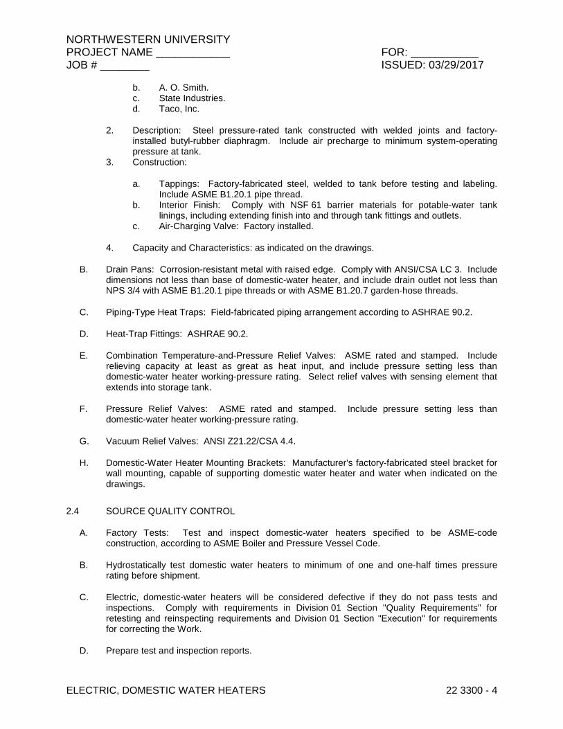
NORTHWESTERN UNIVERSITY PROJECT NAME ____________ FOR: ___________ JOB # ________ ISSUED: 03/29/2017
ELECTRIC, DOMESTIC WATER HEATERS 22 3300 - 4
b. A. O. Smith. c. State Industries. d. Taco, Inc.
2. Description: Steel pressure-rated tank constructed with welded joints and factory-installed butyl-rubber diaphragm. Include air precharge to minimum system-operating pressure at tank.
3. Construction:
a. Tappings: Factory-fabricated steel, welded to tank before testing and labeling. Include ASME B1.20.1 pipe thread.
b. Interior Finish: Comply with NSF 61 barrier materials for potable-water tank linings, including extending finish into and through tank fittings and outlets.
c. Air-Charging Valve: Factory installed.
4. Capacity and Characteristics: as indicated on the drawings.
B. Drain Pans: Corrosion-resistant metal with raised edge. Comply with ANSI/CSA LC 3. Include dimensions not less than base of domestic-water heater, and include drain outlet not less than NPS 3/4 with ASME B1.20.1 pipe threads or with ASME B1.20.7 garden-hose threads.
C. Piping-Type Heat Traps: Field-fabricated piping arrangement according to ASHRAE 90.2.
D. Heat-Trap Fittings: ASHRAE 90.2.
E. Combination Temperature-and-Pressure Relief Valves: ASME rated and stamped. Include relieving capacity at least as great as heat input, and include pressure setting less than domestic-water heater working-pressure rating. Select relief valves with sensing element that extends into storage tank.
F. Pressure Relief Valves: ASME rated and stamped. Include pressure setting less than domestic-water heater working-pressure rating.
G. Vacuum Relief Valves: ANSI Z21.22/CSA 4.4.
H. Domestic-Water Heater Mounting Brackets: Manufacturer's factory-fabricated steel bracket for wall mounting, capable of supporting domestic water heater and water when indicated on the drawings.
2.4 SOURCE QUALITY CONTROL
A. Factory Tests: Test and inspect domestic-water heaters specified to be ASME-code construction, according to ASME Boiler and Pressure Vessel Code.
B. Hydrostatically test domestic water heaters to minimum of one and one-half times pressure rating before shipment.
C. Electric, domestic-water heaters will be considered defective if they do not pass tests and inspections. Comply with requirements in Division 01 Section "Quality Requirements" for retesting and reinspecting requirements and Division 01 Section "Execution" for requirements for correcting the Work.
D. Prepare test and inspection reports.
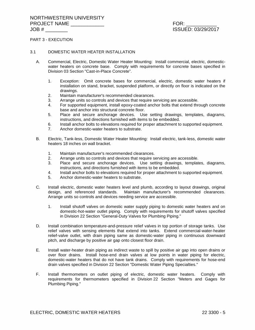
NORTHWESTERN UNIVERSITY PROJECT NAME ____________ FOR: ___________ JOB # ________ ISSUED: 03/29/2017
ELECTRIC, DOMESTIC WATER HEATERS 22 3300 - 5
PART 3 - EXECUTION
3.1 DOMESTIC WATER HEATER INSTALLATION
A. Commercial, Electric, Domestic Water Heater Mounting: Install commercial, electric, domestic-water heaters on concrete base. Comply with requirements for concrete bases specified in Division 03 Section "Cast-in-Place Concrete”.
1. Exception: Omit concrete bases for commercial, electric, domestic water heaters if installation on stand, bracket, suspended platform, or directly on floor is indicated on the drawings.
2. Maintain manufacturer's recommended clearances. 3. Arrange units so controls and devices that require servicing are accessible. 4. For supported equipment, install epoxy-coated anchor bolts that extend through concrete
base and anchor into structural concrete floor. 5. Place and secure anchorage devices. Use setting drawings, templates, diagrams,
instructions, and directions furnished with items to be embedded. 6. Install anchor bolts to elevations required for proper attachment to supported equipment. 7. Anchor domestic-water heaters to substrate.
B. Electric, Tank-less, Domestic Water Heater Mounting: Install electric, tank-less, domestic water heaters 18 inches on wall bracket.
1. Maintain manufacturer's recommended clearances. 2. Arrange units so controls and devices that require servicing are accessible. 3. Place and secure anchorage devices. Use setting drawings, templates, diagrams,
instructions, and directions furnished with items to be embedded. 4. Install anchor bolts to elevations required for proper attachment to supported equipment. 5. Anchor domestic-water heaters to substrate.
C. Install electric, domestic water heaters level and plumb, according to layout drawings, original design, and referenced standards. Maintain manufacturer's recommended clearances. Arrange units so controls and devices needing service are accessible.
1. Install shutoff valves on domestic water supply piping to domestic water heaters and on domestic-hot-water outlet piping. Comply with requirements for shutoff valves specified in Division 22 Section "General-Duty Valves for Plumbing Piping."
D. Install combination temperature-and-pressure relief valves in top portion of storage tanks. Use relief valves with sensing elements that extend into tanks. Extend commercial-water-heater relief-valve outlet, with drain piping same as domestic-water piping in continuous downward pitch, and discharge by positive air gap onto closest floor drain.
E. Install water-heater drain piping as indirect waste to spill by positive air gap into open drains or over floor drains. Install hose-end drain valves at low points in water piping for electric, domestic-water heaters that do not have tank drains. Comply with requirements for hose-end drain valves specified in Division 22 Section "Domestic Water Piping Specialties."
F. Install thermometers on outlet piping of electric, domestic water heaters. Comply with requirements for thermometers specified in Division 22 Section "Meters and Gages for Plumbing Piping."

NORTHWESTERN UNIVERSITY PROJECT NAME ____________ FOR: ___________ JOB # ________ ISSUED: 03/29/2017
ELECTRIC, DOMESTIC WATER HEATERS 22 3300 - 6
G. Install piping-type heat traps on inlet and outlet piping of electric, domestic-water heater storage tanks without integral or fitting-type heat traps.
H. Fill electric, domestic water heaters with water.
I. Charge domestic water compression tanks with air.
3.2 CONNECTIONS
A. Comply with requirements for piping specified in Division 22 Section "Domestic Water Piping." Drawings indicate general arrangement of piping, fittings, and specialties.
B. Where installing piping adjacent to electric, domestic-water heaters, allow space for service and maintenance of water heaters. Arrange piping for easy removal of domestic water heaters.
3.3 IDENTIFICATION
A. Identify system components. Comply with requirements for identification specified in Division 22 Section "Identification for Plumbing Piping and Equipment."
3.4 FIELD QUALITY CONTROL
A. Perform tests and inspections.
1. Manufacturer's Field Service: Engage a factory-authorized service representative to inspect components, assemblies, and equipment installations, including connections, and to assist in testing.
2. Leak Test: After installation, charge system and test for leaks. Repair leaks and retest until no leaks exist.
3. Operational Test: After electrical circuitry has been energized, start units to confirm proper operation.
4. Test and adjust controls and safeties. Replace damaged and malfunctioning controls and equipment.
B. Electric, domestic-water heaters will be considered defective if they do not pass tests and inspections. Comply with requirements in Division 01 Section "Quality Requirements" for retesting and reinspecting requirements and Division 01 Section "Execution" for requirements for correcting the Work.
C. Prepare test and inspection reports.
END OF SECTION 22 3300

NORTHWESTERN UNIVERSITY PROJECT NAME ____________ FOR: ___________ JOB # ________ ISSUED: 03/29/2017
FUEL FIRED, DOMESTIC WATER HEATERS 22 3400 - 1
SECTION 22 3400 - FUEL-FIRED, DOMESTIC WATER HEATERS
PART 1 - GENERAL
1.1 RELATED DOCUMENTS
A. Drawings and general provisions of the Contract, including General and Supplementary Conditions and Division 01 Specification Sections, apply to this Section.
1.2 SUMMARY
A. Section Includes:
1. Commercial, power-burner, gas-fired, storage, domestic water heaters. 2. Domestic-water heater accessories.
1.3 SUBMITTALS
A. Product Data: For each type and size of domestic water heater indicated.
B. LEED Submittal:
1. Product Data for Prerequisite EA 2: Documentation indicating that units comply with ASHRAE/IESNA 90.1, Section 7, "Service Water Heating."
C. Shop Drawings:
1. Wiring Diagrams: For power, signal, and control wiring.
D. Product certificates.
E. Domestic-Water Heater Labeling: Certified and labeled by testing agency acceptable to authorities having jurisdiction.
F. Source quality-control reports.
G. Field quality-control reports.
H. Operation and maintenance data.
I. Warranty: Sample of special warranty.
1.4 QUALITY ASSURANCE
A. Electrical Components, Devices, and Accessories: Listed and labeled as defined in NFPA 70, by a qualified testing agency, and marked for intended location and application.

NORTHWESTERN UNIVERSITY PROJECT NAME ____________ FOR: ___________ JOB # ________ ISSUED: 03/29/2017
FUEL FIRED, DOMESTIC WATER HEATERS 22 3400 - 2
B. ASHRAE/IESNA 90.1 Compliance: Fabricate and label fuel-fired, domestic water heaters to comply with ASHRAE/IESNA 90.1.
C. ASME Compliance:
1. Where ASME-code construction is indicated, fabricate and label commercial, domestic-water heater storage tanks to comply with ASME Boiler and Pressure Vessel Code: Section VIII, Division 1.
2. Where ASME-code construction is indicated, fabricate and label commercial, finned-tube, domestic-water heaters to comply with ASME Boiler and Pressure Vessel Code: Section IV.
D. NSF Compliance: Fabricate and label equipment components that will be in contact with potable water to comply with NSF 61, "Drinking Water System Components - Health Effects."
1.5 WARRANTY
A. Special Warranty: Manufacturer's standard form in which manufacturer agrees to repair or replace components of fuel-fired, domestic water heaters that fail in materials or workmanship within specified warranty period.
1. Warranty Periods: From date of Substantial Completion.
a. Commercial, Gas-Fired, Storage, Domestic Water Heaters:
1) Storage Tank: Three years. 2) Controls and Other Components: One year(s). 3) Compression Tanks: Five years.
PART 2 - PRODUCTS
2.1 COMMERCIAL, GAS-FIRED, STORAGE, DOMESTIC-WATER HEATERS
A. Commercial, Power-Burner, Gas-Fired, Storage, Domestic Water Heaters:
1. Basis-of-Design Product: Subject to compliance with requirements, provide product indicated on the drawings or comparable product by one of the following:
a. A. O. Smith b. Lochivar. c. PVI Industries, LLC. d. State Industries. e. Bradford White
2. Standard: ANSI Z21.10.3/CSA 4.3. 3. Storage Tank Construction: ASME-code steel with 150-psig working-pressure rating.
a. Tappings: Factory fabricated of materials compatible with tank. Attach tappings to tank before testing.
1) Threaded ends according to ASME B1.20.1.
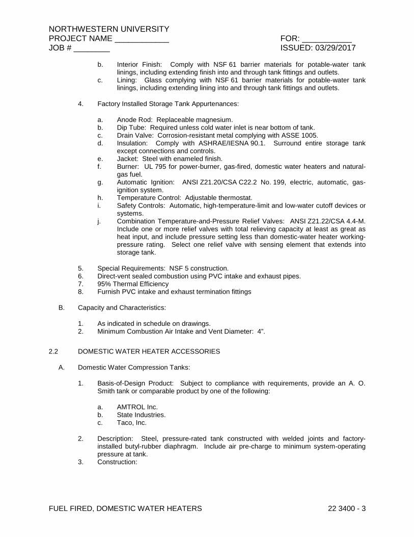
NORTHWESTERN UNIVERSITY PROJECT NAME ____________ FOR: ___________ JOB # ________ ISSUED: 03/29/2017
FUEL FIRED, DOMESTIC WATER HEATERS 22 3400 - 3
b. Interior Finish: Comply with NSF 61 barrier materials for potable-water tank linings, including extending finish into and through tank fittings and outlets.
c. Lining: Glass complying with NSF 61 barrier materials for potable-water tank linings, including extending lining into and through tank fittings and outlets.
4. Factory Installed Storage Tank Appurtenances:
a. Anode Rod: Replaceable magnesium. b. Dip Tube: Required unless cold water inlet is near bottom of tank. c. Drain Valve: Corrosion-resistant metal complying with ASSE 1005. d. Insulation: Comply with ASHRAE/IESNA 90.1. Surround entire storage tank
except connections and controls. e. Jacket: Steel with enameled finish. f. Burner: UL 795 for power-burner, gas-fired, domestic water heaters and natural-
gas fuel. g. Automatic Ignition: ANSI Z21.20/CSA C22.2 No. 199, electric, automatic, gas-
ignition system. h. Temperature Control: Adjustable thermostat. i. Safety Controls: Automatic, high-temperature-limit and low-water cutoff devices or
systems. j. Combination Temperature-and-Pressure Relief Valves: ANSI Z21.22/CSA 4.4-M.
Include one or more relief valves with total relieving capacity at least as great as heat input, and include pressure setting less than domestic-water heater working-pressure rating. Select one relief valve with sensing element that extends into storage tank.
5. Special Requirements: NSF 5 construction. 6. Direct-vent sealed combustion using PVC intake and exhaust pipes. 7. 95% Thermal Efficiency 8. Furnish PVC intake and exhaust termination fittings
B. Capacity and Characteristics:
1. As indicated in schedule on drawings. 2. Minimum Combustion Air Intake and Vent Diameter: 4”.
2.2 DOMESTIC WATER HEATER ACCESSORIES
A. Domestic Water Compression Tanks:
1. Basis-of-Design Product: Subject to compliance with requirements, provide an A. O. Smith tank or comparable product by one of the following:
a. AMTROL Inc. b. State Industries. c. Taco, Inc.
2. Description: Steel, pressure-rated tank constructed with welded joints and factory-installed butyl-rubber diaphragm. Include air pre-charge to minimum system-operating pressure at tank.
3. Construction:

NORTHWESTERN UNIVERSITY PROJECT NAME ____________ FOR: ___________ JOB # ________ ISSUED: 03/29/2017
FUEL FIRED, DOMESTIC WATER HEATERS 22 3400 - 4
a. Tappings: Factory-fabricated steel, welded to tank before testing and labeling. Include ASME B1.20.1 pipe thread.
b. Interior Finish: Comply with NSF 61 barrier materials for potable-water tank linings, including extending finish into and through tank fittings and outlets.
c. Air-Charging Valve: Factory installed.
4. Capacity and Characteristics:
a. Working-Pressure Rating: 150 psig. b. Capacity Acceptable: 10 gal. minimum.
B. Piping-Type Heat Traps: Field-fabricated piping arrangement according to ASHRAE/IESNA 90.1.
C. Heat-Trap Fittings: ASHRAE 90.2.
D. Gas Shutoff Valves: ANSI Z21.15/CSA 9.1-M, manually operated. Furnish for installation in piping.
E. Gas Pressure Regulators: ANSI Z21.18/CSA 6.3, appliance type. Include with pressure rating as required to match gas supply.
F. Automatic Gas Valves: ANSI Z21.21/CSA 6.5, appliance, electrically operated, on-off automatic valve.
G. Combination Temperature-and-Pressure Relief Valves: Include relieving capacity at least as great as heat input, and include pressure setting less than domestic-water heater working-pressure rating. Select relief valves with sensing element that extends into storage tank.
1. Gas-Fired, Domestic Water Heaters: ANSI Z21.22/CSA 4.4-M.
2.3 SOURCE QUALITY CONTROL
A. Factory Tests: Test and inspect assembled domestic-water heaters and storage tanks specified to be ASME-code construction, according to ASME Boiler and Pressure Vessel Code.
B. Hydrostatically test commercial domestic-water heaters and storage tanks to minimum of one and one-half times pressure rating before shipment.
C. Domestic-water heaters will be considered defective if they do not pass tests and inspections. Comply with requirements in Division 01 Section "Quality Requirements" for retesting and reinspecting requirements and Division 01 Section "Execution" for requirements for correcting the Work.
D. Prepare test and inspection reports.

NORTHWESTERN UNIVERSITY PROJECT NAME ____________ FOR: ___________ JOB # ________ ISSUED: 03/29/2017
FUEL FIRED, DOMESTIC WATER HEATERS 22 3400 - 5
PART 3 - EXECUTION
3.1 DOMESTIC WATER HEATER INSTALLATION
A. Commercial, Domestic-Water Heater Mounting: Install commercial domestic water heaters on concrete base. Comply with requirements for concrete base specified in Division 03 Section "Cast-in-Place Concrete."
1. Maintain manufacturer's recommended clearances. 2. Arrange units so controls and devices that require servicing are accessible. 3. Install dowel rods to connect concrete base to concrete floor. Unless otherwise
indicated, install dowel rods on 18-inch centers around the full perimeter of concrete base.
4. For supported equipment, install epoxy-coated anchor bolts that extend through concrete base and anchor into structural concrete floor.
5. Place and secure anchorage devices. Use setting drawings, templates, diagrams, instructions, and directions furnished with items to be embedded.
6. Install anchor bolts to elevations required for proper attachment to supported equipment. 7. Anchor domestic-water heaters to substrate.
B. Install domestic water heaters level and plumb, according to layout drawings, original design, and referenced standards. Maintain manufacturer's recommended clearances. Arrange units so controls and devices needing service are accessible.
1. Install shutoff valves on domestic-water-supply piping to domestic-water heaters and on domestic-hot-water outlet piping. Comply with requirements for shutoff valves specified in Division 22 Section "General-Duty Valves for Plumbing Piping."
C. Install gas-fired, domestic-water heaters according to NFPA 54.
1. Install gas shutoff valves on gas supply piping to gas-fired, domestic water heaters without shutoff valves.
2. Install gas pressure regulators on gas supplies to gas-fired, domestic water heaters without gas pressure regulators if gas pressure regulators are required to reduce gas pressure at burner.
3. Install automatic gas valves on gas supplies to gas-fired, domestic water heaters if required for operation of safety control.
4. Comply with requirements for gas shutoff valves, gas pressure regulators, and automatic gas valves specified in Division 23 Section "Facility Natural-Gas Piping."
D. Extend commercial-water-heater relief-valve outlet, with drain piping same as domestic water piping in continuous downward pitch, and discharge by positive air gap onto closest floor drain.
E. Install thermometer on outlet piping of domestic water heaters. Comply with requirements for thermometers specified in Division 22 Section "Meters and Gages for Plumbing Piping."
F. Install piping-type heat traps on inlet and outlet piping of domestic water heater storage tanks without integral or fitting-type heat traps.
G. Fill domestic-water heaters with water.
H. Charge domestic-water compression tanks with air.
NORTHWESTERN UNIVERSITY PROJECT NAME ____________ FOR: ___________ JOB # ________ ISSUED: 03/29/2017
FUEL FIRED, DOMESTIC WATER HEATERS 22 3400 - 6
3.2 CONNECTIONS
A. Comply with requirements for domestic-water piping specified in Division 22 Section "Domestic Water Piping."
B. Comply with requirements for gas piping specified in Division 23 Section "Facility Natural-Gas Piping."
C. Drawings indicate general arrangement of piping, fittings, and specialties.
D. Where installing piping adjacent to fuel-fired, domestic water heaters, allow space for service and maintenance of water heaters. Arrange piping for easy removal of domestic-water heaters.
3.3 IDENTIFICATION
A. Identify system components. Comply with requirements for identification specified in Division 22 Section "Identification for Plumbing Piping and Equipment."
3.4 FIELD QUALITY CONTROL
A. Perform tests and inspections.
1. Manufacturer's Field Service: Engage a factory-authorized service representative to inspect components, assemblies, and equipment installations, including connections, and to assist in testing.
2. Leak Test: After installation, charge system and test for leaks. Repair leaks and retest until no leaks exist.
3. Operational Test: After electrical circuitry has been energized, start units to confirm proper operation.
4. Test and adjust controls and safeties. Replace damaged and malfunctioning controls and equipment.
B. Domestic water heaters will be considered defective if they do not pass tests and inspections. Comply with requirements in Division 01 Section "Quality Requirements" for retesting and reinspecting requirements and Division 01 Section "Execution" for requirements for correcting the Work.
C. Prepare test and inspection reports.
3.5 DEMONSTRATION
A. Engage a factory-authorized service representative to train Owner's maintenance personnel to adjust, operate, and maintain commercial, gas-fired, storage, domestic-water heaters.
END OF SECTION 22 3400
NORTHWESTERN UNIVERSITY PROJECT NAME ____________ FOR: ___________ JOB # ________ ISSUED: 03/29/2017
DOMESTIC-WATER HEAT EXCHANGERS 22 3500 - 1
SECTION 22 3500 - DOMESTIC-WATER HEAT EXCHANGERS
PART 1 - GENERAL
1.1 RELATED DOCUMENTS
A. Drawings and general provisions of the Contract, including General and Supplementary Conditions and Division 01 Specification Sections, apply to this Section.
1.2 SUMMARY
A. Section Includes:
1. Shell-and-tube, domestic-water-in-coil, domestic-water heat exchangers. 2. Domestic-water, heat-exchanger accessories.
1.3 PERFORMANCE REQUIREMENTS
A. Seismic Performance: Domestic-water heat exchangers shall withstand the effects of earthquake motions determined according to ASCE/SEI 7.
1. The term "withstand" means "the unit will remain in place without separation of any parts from the device when subjected to the seismic forces specified and the unit will be fully operational after the seismic event."
1.4 ACTION SUBMITTALS
A. Product Data: For each type and size of domestic-water heat exchanger indicated. Include rated capacities, operating characteristics, electrical characteristics, and furnished specialties and accessories.
B. Shop Drawings:
1. Wiring Diagrams: For power, signal, and control wiring.
1.5 INFORMATIONAL SUBMITTALS
A. Seismic Qualification Certificates: For domestic-water heat exchangers, accessories, and components, from manufacturer.
1. Basis for Certification: Indicate whether withstand certification is based on actual test of assembled components or on calculation.
2. Dimensioned Outline Drawings of Equipment Unit: Identify center of gravity and locate and describe mounting and anchorage provisions.
NORTHWESTERN UNIVERSITY PROJECT NAME ____________ FOR: ___________ JOB # ________ ISSUED: 03/29/2017
DOMESTIC-WATER HEAT EXCHANGERS 22 3500 - 2
3. Detailed description of equipment anchorage devices on which the certification is based and their installation requirements.
B. Product Certificates: For each type of shell-and-tube, domestic-water heat exchanger, from manufacturer.
C. Domestic-Water, Heat-Exchanger Labeling: Certified and labeled by testing agency acceptable to authorities having jurisdiction.
D. Source quality-control reports.
E. Field quality-control reports.
F. Warranty: Sample of special warranty.
1.6 CLOSEOUT SUBMITTALS
A. Operation and Maintenance Data: For domestic-water heat exchangers to include in emergency, operation, and maintenance manuals.
1.7 QUALITY ASSURANCE
A. Electrical Components, Devices, and Accessories: Listed and labeled as defined in NFPA 70, by a qualified testing agency, and marked for intended location and application.
B. ASHRAE/IESNA 90.1 Compliance: Applicable requirements in ASHRAE/IESNA 90.1.
C. ASME Compliance: Where ASME-code construction is indicated, fabricate and label heat-exchanger storage tanks to comply with ASME Boiler and Pressure Vessel Code: Section VIII, Division 1.
D. NSF Compliance: Fabricate and label equipment components that will be in contact with potable water to comply with NSF 61, "Drinking Water System Components - Health Effects."
1.8 COORDINATION
A. Coordinate sizes and locations of concrete bases with actual equipment provided.
1.9 WARRANTY
A. Special Warranty: Manufacturer's standard form in which manufacturer agrees to repair or replace components of domestic-water heat exchangers that fail in materials or workmanship within specified warranty period.
1. Failures include, but are not limited to, the following:
a. Structural failures including heat exchanger, storage tank, and supports. b. Faulty operation of controls. c. Deterioration of metals, metal finishes, and other materials beyond normal use.
NORTHWESTERN UNIVERSITY PROJECT NAME ____________ FOR: ___________ JOB # ________ ISSUED: 03/29/2017
DOMESTIC-WATER HEAT EXCHANGERS 22 3500 - 3
2. Warranty Periods: From date of Substantial Completion.
a. Shell-and-Tube, Domestic-Water Heat Exchangers:
1) Tube Coil: One year. 2) Controls and Other Components: One year.
b. Compression Tanks: One year.
PART 2 - PRODUCTS
2.1 SEMI-INSTANTANEOUS DOMESTIC-WATER HEAT EXCHANGERS
A. Semi-Instantaneous, Domestic-Water Heat Exchangers:
1. Manufacturers: Subject to compliance with requirements, provide products by one of the following:
a. PVI Industries, LLC b. Patterson-Kelley; a division of Harsco Corporation c. Ajax Boiler Inc.
2. Description: Packaged, small-capacity hot-water storage tank with heat-exchanger coil; circulator; controls; and specialties for heating domestic water with steam in coil.
3. Storage-Tank Construction: ASME-code steel with 150-psig (1035-kPa) working-pressure rating. Include nozzle and head for heat-exchanger tube coil.
a. Configuration: Vertical. b. Tappings: Factory fabricated of materials compatible with tank. Attach tappings to
tank before testing and labeling.
1) NPS 2 (DN 50) and Smaller: Threaded ends according to ASME B1.20.1. 2) NPS 2-1/2 (DN 65) and Larger: Flanged ends according to ASME B16.5 for
steel and stainless-steel flanges and according to ASME B16.24 for copper and copper-alloy flanges.
c. Lining: Nickel plate complying with NSF 61 barrier materials for potable-water tank linings, including extending lining into and through tank fittings and outlets. Provide secondary overcoat of Polyshieldpolymeron interior of vessel.
d. Insulation: Complying with ASHRAE/IESNA 90.1, unless otherwise indicated, and suitable for operating temperature. Surround entire storage tank and nozzle except connections and controls.
e. Anode Rods: Factory installed, magnesium, for glass lined vessels only
4. Heat-Exchanger Coil: Vented, double-wall, copper or copper-alloy U tubes with tube sheet and supporting baffles. Include heat-exchanger pressure rating equal to or greater than heating-fluid supply pressure. Provide Y strainer and F&T trap and all other required accessories for a complete operating system
5. Temperature Control: Adjustable electronic immersion operating thermostat mounted in storage-tank shell head unless otherwise indicated.

NORTHWESTERN UNIVERSITY PROJECT NAME ____________ FOR: ___________ JOB # ________ ISSUED: 03/29/2017
DOMESTIC-WATER HEAT EXCHANGERS 22 3500 - 4
6. Safety Control: Automatic, high-temperature-limit cutoff device or system. Include automatic low-water cutoff device or system.
7. Relief Valves: ASME rated and stamped for combination temperature-and-pressure relief valves. Include one or more relief valves with total relieving capacity at least as great as heat input, and include pressure setting less than working-pressure rating of heat exchanger. Select one relief valve with sensing element that extends into storage tank.
8. Gages: Factory-mounted thermometer and pressure gage. 9. Circulating Pump: UL 778, all-bronze, centrifugal, overhung-impeller, separately coupled
in-line pump as defined in HI 1.1-1.2 and HI 1.3. Include mechanical seals, 125-psig minimum working-pressure rating, and 225 deg F continuous-water-temperature rating.
a. Pump Control: Sensor for operating pump and control valve.
10. Support: Factory mounted on skids.
2.2 DOMESTIC-WATER, HEAT-EXCHANGER ACCESSORIES
A. Domestic-Water Compression Tanks:
1. Manufacturers: Subject to compliance with requirements, provide products by one of the following:
a. AMTROL Inc. b. Pentair Pump Group (The); Myers. c. Smith, A. O. Water Products Co.; a division of A. O. Smith Corporation. d. State Industries. e. Taco, Inc.
2. Description: Steel pressure-rated tank constructed with welded joints and factory-installed butyl-rubber diaphragm. Include air precharge to minimum system-operating pressure at tank.
3. Construction:
a. Tappings: Factory-fabricated steel, welded to tank before testing and labeling. Include ASME B1.20.1 pipe thread.
b. Interior Finish: Comply with NSF 61 barrier materials for potable-water tank linings, including extending finish into and through tank fittings and outlets.
c. Air-Charging Valve: Factory installed.
B. Piping-Type Heat Traps: Field-fabricated piping arrangement according to ASHRAE/IESNA 90.1[ or ASHRAE 90.2].
C. Heat-Trap Fittings: ASHRAE 90.2.
D. Combination Temperature-and-Pressure Relief Valves: ASME rated and stamped. Include relieving capacity at least as great as heat input, and include pressure setting less than heat-exchanger working-pressure rating. Select relief valves with sensing element that extends into storage tank.
E. Pressure Relief Valves: ASME rated and stamped. Include pressure setting less than heat-exchanger working-pressure rating.
F. Vacuum Relief Valves: ANSI Z21.22/CSA 4.4-M.
NORTHWESTERN UNIVERSITY PROJECT NAME ____________ FOR: ___________ JOB # ________ ISSUED: 03/29/2017
DOMESTIC-WATER HEAT EXCHANGERS 22 3500 - 5
2.3 SOURCE QUALITY CONTROL
A. Factory Tests: Test and inspect domestic-water heat exchangers specified to be ASME-code construction, according to ASME Boiler and Pressure Vessel Code.
B. Hydrostatically test domestic-water heat exchangers to minimum of one and one-half times pressure rating before shipment.
C. Domestic-water heat exchangers will be considered defective if they do not pass tests and inspections. Comply with requirements in Section 014000 "Quality Requirements" for retesting and reinspecting requirements and Section 017300 "Execution" for requirements for correcting the Work.
D. Prepare test and inspection reports.
PART 3 - EXECUTION
3.1 DOMESTIC-WATER, HEAT-EXCHANGER INSTALLATION
A. Domestic-Water, Heat-Exchanger Mounting: Install domestic-water heat exchangers on concrete base. Comply with requirements for concrete bases specified in [Section 033000 "Cast-in-Place Concrete."] [Section 033053 "Miscellaneous Cast-in-Place Concrete."]
1. Install dowel rods to connect concrete base to concrete floor. Unless otherwise indicated, install dowel rods on 18-inch (450-mm) centers around the full perimeter of concrete base.
2. For supported equipment, install epoxy-coated anchor bolts that extend through concrete base and anchor into structural concrete floor.
3. Place and secure anchorage devices. Use setting drawings, templates, diagrams, instructions, and directions furnished with items to be embedded.
4. Install anchor bolts to elevations required for proper attachment to supported equipment. 5. Anchor heat exchangers to substrate.
B. Install domestic-water heat exchangers level and plumb, according to layout drawings, original design, and referenced standards. Maintain manufacturer's recommended clearances. Arrange units so controls and devices needing service are accessible.
1. Install shutoff valves on domestic-water-supply piping to heat exchangers and on domestic-hot-water outlet piping. Comply with requirements for shutoff valves specified in Section 220523 "General-Duty Valves for Plumbing Piping."
2. Install shutoff valves on heating hot-water piping to heat exchangers. Comply with requirements for shutoff valves specified in Section 230523 "General-Duty Valves for HVAC Piping."
3. Install shutoff valves on steam and condensate piping to heat exchangers. Comply with requirements for shutoff valves specified in Section 230523 "General-Duty Valves for HVAC Piping."
C. Install domestic-water heat exchangers with seismic-restraint devices. Comply with requirements for seismic-restraint devices specified in Section 220548 "Vibration and Seismic Controls for Plumbing Piping and Equipment."
NORTHWESTERN UNIVERSITY PROJECT NAME ____________ FOR: ___________ JOB # ________ ISSUED: 03/29/2017
DOMESTIC-WATER HEAT EXCHANGERS 22 3500 - 6
D. Install temperature and pressure relief valves in top portion of storage-tank shells of domestic-water heat exchangers with domestic-water storage. Use relief valves with sensing elements that extend into shells. Extend relief-valve outlet, with drain piping same as domestic-water piping in continuous downward pitch, and discharge by positive air gap onto closest floor drain.
E. Install combination temperature-and-pressure relief valves in water piping for domestic-water heat exchangers without storage. Extend relief-valve outlet, with drain piping same as domestic-water piping in continuous downward pitch, and discharge by positive air gap onto closest floor drain.
F. Install heat-exchanger drain piping as indirect waste to spill by positive air gap into open drains or over floor drains. Install hose-end drain valves at low points in water piping for domestic-water heat exchangers that do not have tank drains. Comply with requirements for hose-end drain valves specified in Section 221119 "Domestic Water Piping Specialties."
G. Install thermometer on each domestic-water, heat-exchanger, inlet and outlet piping, and install thermometer on each domestic-water, heat-exchanger, heating-fluid inlet and outlet piping. Comply with requirements for thermometers specified in Section 220519 "Meters and Gages for Plumbing Piping."
H. Install pressure gages on domestic-water, heat-exchanger, heating-fluid piping. Comply with requirements for pressure gages specified in Section 220519 "Meters and Gages for Plumbing Piping."
I. Fill domestic-water heat exchangers with water.
J. Charge domestic-water compression tanks with air.
3.2 CONNECTIONS
A. Comply with requirements for piping specified in Section 221116 "Domestic Water Piping."
B. Comply with requirements for heating hot-water piping specified in Section 232113 "Hydronic Piping."
C. Comply with requirements for steam and condensate piping specified in Section 232213 "Steam and Condensate Heating Piping."
D. Drawings indicate general arrangement of piping, fittings, and specialties.
E. Where installing piping adjacent to domestic-water heat exchangers, allow space for service and maintenance of heat exchangers. Arrange piping for easy removal of domestic-water heat exchangers.
3.3 IDENTIFICATION
A. Identify system components. Comply with requirements for identification specified in Section 220553 "Identification for Plumbing Piping and Equipment."

NORTHWESTERN UNIVERSITY PROJECT NAME ____________ FOR: ___________ JOB # ________ ISSUED: 03/29/2017
DOMESTIC-WATER HEAT EXCHANGERS 22 3500 - 7
3.4 FIELD QUALITY CONTROL
A. Perform tests and inspections.
1. Manufacturer's Field Service: Engage a factory-authorized service representative to inspect components, assemblies, and equipment installations, including connections, and to assist in testing.
2. Leak Test: After installation, charge system and test for leaks. Repair leaks and retest until no leaks exist.
3. Operational Test: After electrical circuitry has been energized, start units to confirm proper operation.
4. Test and adjust controls and safeties. Replace damaged and malfunctioning controls and equipment.
B. Domestic-water heat exchangers will be considered defective if they do not pass tests and inspections. Comply with requirements in Section 014000 "Quality Requirements" for retesting and reinspecting requirements and Section 017300 "Execution" for requirements for correcting the Work.
C. Prepare test and inspection reports.
3.5 DEMONSTRATION
A. Engage a factory-authorized service representative to train maintenance personnel to adjust, operate, and maintain shell-and-tube domestic-water heat exchangers.
END OF SECTION 22 3500
NORTHWESTERN UNIVERSITY PROJECT NAME ____________ FOR: ___________ JOB # ________ ISSUED: 03/29/2017
DOMESTIC-WATER HEAT EXCHANGERS 22 3500 - 8
THIS PAGE IS INTENTIONALLY BLANK
NORTHWESTERN UNIVERSITY PROJECT NAME ____________ FOR: ___________ JOB # ________ ISSUED: 03/29/2017
PLUMBING FIXTURES 22 4000 - 1
SECTION 22 4000 - PLUMBING FIXTURES
PART 1 - GENERAL
1.1 RELATED DOCUMENTS
A. Drawings and general provisions of the Contract, including General and Supplementary Conditions and Division 01 Specification Sections, apply to this Section.
1.2 SUMMARY
A. This Section includes the following:
1. Faucets for lavatories and showers. 2. Flushometers for water closets and urinals. 3. Toilet seats. 4. Protective shielding guards. 5. Fixture supports. 6. Water closets. 7. Urinals. 8. Lavatories. 9. Sinks and sink faucets. 10. Service sinks and faucets. 11. Mop sinks and faucets. 12. Lab faucets. 13. Shower cabinets. 14. Shower receptors.
B. Related Sections include the following:
1. Section 22 1118 "Domestic Water Distribution System." 2. Section 22 2114 "Plumbing Specialties."
1.3 DEFINITIONS
A. ABS: Acrylonitrile-butadiene-styrene plastic.
B. Accessible Fixture: Plumbing fixture that can be approached, entered, and used by people with disabilities.
C. FRP: Fiberglass-reinforced plastic.
D. PMMA: Polymethyl methacrylate (acrylic) plastic.
E. PVC: Polyvinyl chloride plastic.
F. Solid Surface: Nonporous, homogeneous, cast-polymer-plastic material with heat-, impact-, scratch-, and stain-resistance qualities.
NORTHWESTERN UNIVERSITY PROJECT NAME ____________ FOR: ___________ JOB # ________ ISSUED: 03/29/2017
PLUMBING FIXTURES 22 4000 - 2
1.4 SUBMITTALS
A. Product Data: For each type of product indicated, and including fixture/item dimensions and rough-in dimensions.
B. [LEED Submittal:
1. Product Data for Credit WE 2, 3.1, and 3.2: Documentation indicating flow and water consumption requirements.
2. Compliance documentation for meeting California Health and Safety Code 116875 (AB 1953) - 2010, for 25% low lead content of piping, pipe fittings, and faucets for water intended for human consumption, and NSF/ANSI Standard 61, including Annex G-2010 - Drinking Water System Components - Low Lead Content Requirement.]
C. Shop Drawings: Diagram power, signal, and control wiring, and for fixture supports and carriers.
D. Operation and maintenance data.
E. At closeout, Northwestern University Maintenance Requirement Forms, see Division 01 for more information.
1.5 QUALITY ASSURANCE
A. Electrical Components, Devices, and Accessories: Listed and labeled as defined in NFPA 70, Article 100, by a testing agency acceptable to authorities having jurisdiction, and marked for intended use.
B. Regulatory Requirements: Comply with requirements in ICC A117.1, "Accessible and Usable Buildings and Facilities"; Public Law 90-480, "Architectural Barriers Act"; and Public Law 101-336, "Americans with Disabilities Act"; for plumbing fixtures for people with disabilities.
C. Regulatory Requirements: Comply with requirements in Public Law 102-486, "Energy Policy Act," about water flow and consumption rates for plumbing fixtures.
D. Comply with California Health and Safety Code 116875 (AB 1953) - 2010, for 25% low lead content of piping, pipe fittings, and faucets for water intended for human consumption, and NSF/ANSI Standard 61, including Annex G-2010 - Drinking Water System Components - Low Lead Content Requirement.
E. Comply with NSF/ANSI 372 - Low Lead Content Verification Requirement
F. Select combinations of fixtures and trim, faucets, fittings, and other components that are compatible.
G. Comply with the following applicable standards and other requirements specified for plumbing fixtures:
1. Enameled, Cast-Iron Fixtures: ASME A112.19.1M. 2. Stainless-Steel Sinks: ASME A112.19.3. 3. Vitreous-China Fixtures: ASME A112.19.2M. 4. Water-Closet, Flush Valve, Tank Trim: ASME A112.19.5.
NORTHWESTERN UNIVERSITY PROJECT NAME ____________ FOR: ___________ JOB # ________ ISSUED: 03/29/2017
PLUMBING FIXTURES 22 4000 - 3
5. Water-Closet, Flushometer Tank Trim: ASSE 1037.
H. Comply with the following applicable standards and other requirements specified for lavatory and sink faucets:
1. Backflow Protection Devices for Faucets with Side Spray: ASME A112.18.3M. 2. Backflow Protection Devices for Faucets with Hose-Thread Outlet: ASME A112.18.3M. 3. Diverter Valves for Faucets with Hose Spray: ASSE 1025. 4. Faucets: ASME A112.18.1. 5. Hose-Connection Vacuum Breakers: ASSE 1011. 6. Hose-Coupling Threads: ASME B1.20.7. 7. Integral, Atmospheric Vacuum Breakers: ASSE 1001. 8. NSF Potable-Water Materials: NSF 61. 9. Pipe Threads: ASME B1.20.1. 10. Sensor-Actuated Faucets and Electrical Devices: UL 1951. 11. Supply Fittings: ASME A112.18.1. 12. Brass Waste Fittings: ASME A112.18.2.
I. Comply with the following applicable standards and other requirements specified for shower faucets:
1. Backflow Protection Devices for Hand-Held Showers: ASME A112.18.3M. 2. Combination, Pressure-Equalizing and Thermostatic-Control Antiscald Faucets:
ASSE 1016. 3. Faucets: ASME A112.18.1. 4. Hand-Held Showers: ASSE 1014. 5. High-Temperature-Limit Controls for Thermal-Shock-Preventing Devices: ASTM F 445. 6. Hose-Coupling Threads: ASME B1.20.7. 7. Manual-Control Antiscald Faucets: ASTM F 444. 8. Pipe Threads: ASME B1.20.1. 9. Pressure-Equalizing-Control Antiscald Faucets: ASTM F 444 and ASSE 1016. 10. Sensor-Actuated Faucets and Electrical Devices: UL 1951. 11. Thermostatic-Control Antiscald Faucets: ASTM F 444 and ASSE 1016.
J. Comply with the following applicable standards and other requirements specified for miscellaneous fittings:
1. Atmospheric Vacuum Breakers: ASSE 1001. 2. Brass and Copper Supplies: ASME A112.18.1. 3. Manual-Operation Flushometers: ASSE 1037. 4. Plastic Tubular Fittings: ASTM F 409. 5. Brass Waste Fittings: ASME A112.18.2. 6. Sensor-Operation Flushometers: ASSE 1037 and UL 1951.
K. Comply with the following applicable standards and other requirements specified for miscellaneous components:
1. Flexible Water Connectors: ASME A112.18.6. 2. Hose-Coupling Threads: ASME B1.20.7. 3. Off-Floor Fixture Supports: ASME A112.6.1M. 4. Pipe Threads: ASME B1.20.1. 5. Plastic Toilet Seats: ANSI Z124.5-2013. 6. Supply and Drain Protective Shielding Guards: ICC A117.1.
NORTHWESTERN UNIVERSITY PROJECT NAME ____________ FOR: ___________ JOB # ________ ISSUED: 03/29/2017
PLUMBING FIXTURES 22 4000 - 4
1.6 SPECIAL WARRANTIES
A. Five (5) years, see Division 01 for more information.
PART 2 - PRODUCTS
2.1 MANUFACTURERS
A. For flushing fixtures, lavatories, showers, service sinks, and mop sinks specified below, subject to compliance with requirements, provide the products indicated in the Fixture Schedule on the drawings, or a comparable product by one of the following:
1. Kohler (preferred). 2. American Standard (acceptable alternate).
B. For Non-Lab duty faucets, subject to compliance with requirements, provide the products indicated in the Fixture Schedule on the drawings, or a comparable product by one of the following:
1. Chicago Faucet. 2. Kohler. 3. Moen. 4. Sloan Valve.
C. For water closet and urinal flushometers, subject to compliance with requirements, provide the products indicated in the Fixture Schedule on the drawings, or a comparable product by one of the following:
1. Moen (preferred). 2. Sloan Valve.
2.2 LAVATORY FAUCETS
A. Lavatory Faucets, L-1 or LF-1:
1. Description: Single-control manual mixing valve. Include hot- and cold-water indicators; coordinate faucet inlets with supplies and fixture holes; coordinate outlet with spout and fixture receptor.
a. Body Material: Commercial, solid brass. b. Finish: Polished chrome plate. c. Maximum Flow Rate: 0.5 gpm. d. Centers: 4 inches. e. Mounting: Deck, exposed. f. Valve Handle: Lever. g. Inlets: NPS 3/8 tubing, with NPS 1/2 male adaptor. h. Spout: Rigid type. i. Spout Outlet: Spray, 0.5 gpm. j. Operation: Non-compression, manual. k. Drain: Grid.

NORTHWESTERN UNIVERSITY PROJECT NAME ____________ FOR: ___________ JOB # ________ ISSUED: 03/29/2017
PLUMBING FIXTURES 22 4000 - 5
****OR****
B. Lavatory Faucets, L-1 or LF-1:
1. Description: ADA compliant, electrically powered, sensor operated faucet. Coordinate faucet inlets with supplies and fixture holes; coordinate outlet with spout and fixture receptor.
a. Body Material: Commercial, solid brass. b. Finish: Polished chrome plate. c. Maximum Flow Rate: 0.5 gpm. d. Centers: 4 inches. e. Mounting: Deck, exposed. f. Inlet(s): NPS 3/8 tubing, with NPS 1/2 male adaptor. g. Spout: Rigid type. h. Spout Outlet: Laminar flow, 0.5 gpm. i. Operation: sensor actuator, hardwired. j. Drain: Grid.
C. Lavatory Faucets, L-2 or LF-2:
1. Description: Single-control manual mixing valve. Include hot and cold water indicators; coordinate faucet inlets with supplies and fixture holes; coordinate outlet with spout and fixture receptor.
a. Body Material: Commercial, solid brass. b. Finish: Polished chrome plate. c. Maximum Flow Rate: 0.5 gpm. d. Centers: 8 inches. e. Mounting: Deck, exposed. f. Valve Handle: Lever. g. Inlets: NPS 3/8 tubing, with NPS 1/2 male adaptor. h. Spout: Swing gooseneck, with dimensions to best serve lavatory use in each
location. i. Spout Outlet: Laminar flow, 0.5 gpm. j. Operation: Non-compression, manual. k. Drain: Grid. ****OR****
D. Lavatory Faucets, L-2 or LF-2:
1. Description: ADA compliant, electrically powered, sensor operated faucet. Coordinate faucet inlets with supplies and fixture holes; coordinate outlet with spout and fixture receptor.
a. Body Material: Commercial, solid brass. b. Finish: Polished chrome plate. c. Maximum Flow Rate: 0.5 gpm. d. Centers: 8 inches. e. Mounting: Deck, exposed. f. Inlet(s): NPS 3/8 tubing, with NPS 1/2 male adaptor. g. Spout: Swing gooseneck, with dimensions to best serve lavatory use in each
location Rigid type.

NORTHWESTERN UNIVERSITY PROJECT NAME ____________ FOR: ___________ JOB # ________ ISSUED: 03/29/2017
PLUMBING FIXTURES 22 4000 - 6
h. Spout Outlet: Laminar flow, 0.5 gpm. i. Operation: sensor actuator, hardwired. j. Drain: Grid.
2.3 SHOWER FAUCETS
A. Shower Faucets, SH-1:
1. Basis-of-Design Product: Subject to compliance with requirements, provide the product indicated the following:
a. Moen Commercial
2. Description: Single-handle pressure-balance valve. Include hot- and cold-water indicators; check stops; and shower head, arm, and flange. Coordinate faucet inlets with supplies and outlet with diverter valve.
a. Valve Body Material: Solid brass. b. Valve Body Finish: Polished chrome plate. c. Maximum Flow Rate: 2.5 gpm. d. Mounting: Concealed. e. Antiscald Device: Integral with mixing valve. f. Check Stops: Check-valve type, integral with or attached to body; on hot- and
cold-water supply connections. g. Supply Connections: 1/2" NPT. h. Shower Head Type: Ball standard institutional showerhead with mounting flange. i. Shower Head Material: Chrome plated brass arm with stainless steel wall flange. j. Spray Pattern: Adjustable. k. Integral Volume Control: Not required. l. Shower-Arm Flow-Control Fitting: 1.5 gpm.
B. Shower Faucets, SH-2:
1. Basis-of-Design Product: Subject to compliance with requirements, provide the product indicated by the following:
a. Moen Commercial
2. Description: Prefabricated stainless steel shower unit with a single-handle pressure-balance valve. Include hot- and cold-water indicators; check stops; and shower head, arm, and flange, and hand held shower with 24” slide bar.
a. Valve Body Material: Solid brass. b. Valve Body Finish: Polished chrome plate. c. Shroud: 18 gage stainless steel brushed finish with extension to conceal piping
thru ceiling. d. Maximum Flow Rate: 2.0 gpm. e. Mounting: Exposed. f. Backflow Protection Device for Hand-Held Shower: Required. g. Antiscald Device: Integral with mixing valve. h. Check Stops: Check-valve type, integral with or attached to body; on hot- and
cold-water supply connections. i. Supply Connections: Sweat.
NORTHWESTERN UNIVERSITY PROJECT NAME ____________ FOR: ___________ JOB # ________ ISSUED: 03/29/2017
PLUMBING FIXTURES 22 4000 - 7
j. Shower Head Type: Ball joint and head integral with mounting flange and hand held, slide-bar mounted spray head.
k. Shower Head Material: Metallic with chrome-plated finish. l. Spray Pattern: Adjustable. m. Diverter Valve: Required. n. Integral Volume Control: Not required. o. Shower-Arm Flow-Control Fitting: 1.5 gpm.
2.4 FLUSHOMETERS
A. Water Closet Flushometers, WC-1 & -2:
1. Description: Exposed, electrically powered, sensor operated, piston type flushometer for water-closet-type fixture. Include brass body with corrosion-resistant internal components, control stop with check valve, vacuum breaker, copper or brass tubing, and polished chrome-plated finish on exposed parts.
a. Internal Design: Piston operation. b. Style: Exposed. c. Inlet Size: NPS 1. d. Trip Mechanism: Battery powered operated sensor actuator. e. Consumption: 1.6 [1.28] gal/flush. f. Tailpiece Size: NPS 1-1/2 and standard length to top of bowl. g. Manual override button.
B. Flushometers, UR-1 & -2:
1. Description: Exposed, electrically powered, sensor operated, piston type flushometer for urinal-type fixture. Include brass body with corrosion-resistant internal components, control stop with check valve, vacuum breaker, copper or brass tubing, and polished chrome-plated finish on exposed parts.
a. Internal Design: Piston operation. b. Style: Exposed. c. Inlet Size: NPS 3/4. d. Trip Mechanism: Battery powered operated sensor actuator. e. Consumption: 0.5 [0.125] gal/flush. f. Tailpiece Size: NPS 3/4 and standard length to top of urinal. g. Manual override button.
2.5 TOILET SEATS
A. Toilet Seats:
1. Manufacturers: Subject to compliance with requirements, provide products by one of the following:
a. American Standard. b. Bemis Manufacturing Company, Duraguard (Basis of Design). c. Church Seats. d. Olsonite Corp.

NORTHWESTERN UNIVERSITY PROJECT NAME ____________ FOR: ___________ JOB # ________ ISSUED: 03/29/2017
PLUMBING FIXTURES 22 4000 - 8
2. Description: Toilet seat for water-closet-type fixture, heavy duty commercial.
a. Material: Molded, solid plastic with antimicrobial agent. b. Configuration: Open front without cover. c. Size: To fit bowl. d. Hinge Type: Self-sustaining. e. Class: Heavy-duty commercial. f. Color: White. g. Fasteners: 300 series stainless steel.
2.6 PROTECTIVE SHIELDING GUARDS
A. Protective Shielding Pipe Covers:
1. Manufacturers: Subject to compliance with requirements, provide products by one of the following:
a. Plumberex Specialty Products Inc. b. TRUEBRO, Inc. c. Zurn Plumbing Products Group; Tubular Brass Plumbing Products Operation.
2. Description: Manufactured plastic wraps for covering plumbing fixture hot- and cold-water supplies and trap and drain piping. Comply with Americans with Disabilities Act (ADA) requirements.
2.7 FIXTURE SUPPORTS
A. Manufacturers for Water Closet Supports: Subject to compliance with requirements, provide products by one of the following:
1. Josam Company 2. Smith, Jay R. Mfg. Co. 3. Tyler Pipe; Wade Div. 4. Zurn Plumbing Products Group; Specification Drainage Operation.
B. Water-Closet Supports:
1. Description: Combination carrier designed for accessible or standard mounting as indicated on drawings, for height of wall-mounting, water-closet-type fixture. Include single or double, vertical or horizontal, hub-and-spigot or hubless waste fitting as required for piping arrangement; faceplates; couplings with gaskets; feet; and fixture bolts and hardware matching fixture. Include additional extension coupling, faceplate, and feet for installation in wide pipe space. Carrier must meet the 500 lb. minimum load bearing requirements of ASME A112.19.2-2005/CSA B45.1-05.
C. Urinal Supports:
1. Description: Wall plate.
D. Lavatory Supports:
1. Description: Wall plate.

NORTHWESTERN UNIVERSITY PROJECT NAME ____________ FOR: ___________ JOB # ________ ISSUED: 03/29/2017
PLUMBING FIXTURES 22 4000 - 9
E. Water Cooler Supports:
1. Wall plates.
2.8 WATER CLOSETS
A. Water Closets, WC-1 & WC-2:
1. Description: Accessible, wall-mounting, back-outlet, vitreous-china fixture designed for flushometer valve operation.
a. Bowl Type: Elongated with siphon-jet design. Include bolt caps matching fixture. b. Surface: Antimicrobial surface which inhibits the growth of stain and odor causing
bacteria. c. Height: Standard for WC-1 and ADA for WC-2. d. Design Consumption: 1.6 [1.28] gal/flush. e. Color: White. f. Basis of Design: Kohler K-4325-0 "Kingston" model.
2. Description: Accessible, floor-mounting, bottom outlet, vitreous-china fixture designed for flushometer valve operation.
a. Bowl Type: Elongated with siphon-jet design. Include bolt caps matching fixture. b. Surface: Antimicrobial surface which inhibits the growth of stain and odor causing
bacteria. c. Height: Standard for WC-1 and ADA for WC-2. d. Design Consumption: 1.6 [1.28] gal/flush. e. Color: White. f. Basis of Design: Kohler K-4302-0 "Highcrest" model
3. Description: Accessible, floor-mounting, tank type, bottom outlet, vitreous-china fixture.
a. Bowl Type: Elongated with siphon-jet design. Include bolt caps matching fixture. b. Surface: Antimicrobial surface which inhibits the growth of stain and odor causing
bacteria. c. Height: Standard for WC-1 and ADA for WC-2. d. Design Consumption: 1.6 [1.28] gal/flush. e. Color: White. f. Basis of Design: Kohler K-3887-0 "Cimarron" model.
2.9 URINALS
A. Urinals, UR-1 & UR-2:
1. Description: Accessible, wall-mounting, back-outlet, vitreous-china fixture designed for flushometer valve operation.
a. Type: Siphon jet. b. Strainer or Trapway: Integral cast strainer with integral trap. c. Design Consumption: 0.5 gal/flush. d. Color: White. e. Supply Spud Size: ¾ inch. f. Outlet Size: 2 inch.

NORTHWESTERN UNIVERSITY PROJECT NAME ____________ FOR: ___________ JOB # ________ ISSUED: 03/29/2017
PLUMBING FIXTURES 22 4000 - 10
g. Height: 24 inch for UR-1 & 17 inch for UR-2. h. Basis of Design: Kohler Dexter K-5016-ET-0.
2.10 LAVATORIES
A. Lavatories, L-1:
1. Description: Accessible, wall mounted, vitreous-china fixture.
a. Type: Wall mounted with front overflow and backsplash. b. Size (nominal): XX [20] by XX [18] inches. c. Faucet Hole Punching: [4 inch centers] [8 inch centers]. d. Color: White. e. Supplies: 3/8 inch chrome-plated copper with stops. f. Drain: Grid g. Drain Piping: 1-1/4 by 1-1/2 inch chrome-plated, cast-brass P-trap; 1-1/2 inch,
0.045-inch- thick tubular brass waste to wall; and wall escutcheon. h. Fixture Support: Required. i. Protective Shielding Guards: Required. j. Basis of Design: Kohler K-2030-0 "Greenwich" for 8" centers, Kohler K-2032-0
"Greenwich" for 4" centers.
B. Lavatories, L-2:
1. Description: Accessible, countertop, vitreous-china fixture.
a. Type: Self-rimming countertop type with front overflow. b. Size (nominal): XX [20] by xx [18] inches. c. Faucet Hole Punching: [4 inch centers] [8 inch centers]. d. Color: White. e. Supplies: NPS 3/8 chrome-plated copper with stops. f. Drain: Grid. g. Drain Piping: 1-1/4 x 1-1/2 inch chrome-plated, cast-brass P-trap; 1-1/2 inch,
0.045-inch- thick tubular brass waste to wall; and wall escutcheon. h. Protective Shielding Guards: Required. i. Basis of Design: Kohler K-2337-8 "Memoirs" for 8" centers, Kohler K-2337-
"Memoirs" for 4" centers.
2.11 SINKS
A. Sinks, S-1 & S-2:
1. Subject to compliance with requirements, provide the product indicated in the Fixture Schedule on the drawings or a comparable product by one of the following:
a. Elkay. b. Just Manufacturing Company. c. Moen Commercial
2. Description: One or Two-bowl, as indicated below or as scheduled, counter-mounted, self rimming stainless-steel sink.
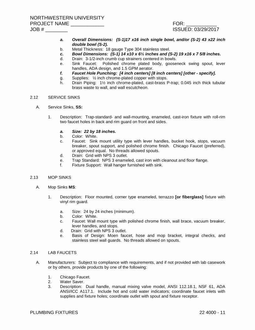
NORTHWESTERN UNIVERSITY PROJECT NAME ____________ FOR: ___________ JOB # ________ ISSUED: 03/29/2017
PLUMBING FIXTURES 22 4000 - 11
a. Overall Dimensions: (S-1)17 x16 inch single bowl, and/or (S-2) 43 x22 inch double bowl (S-2).
b. Metal Thickness: 18 gauge Type 304 stainless steel. c. Bowl Dimensions: (S-1) 14 x10 x 6½ inches and (S-2) 19 x16 x 7 5/8 inches. d. Drain: 3-1/2-inch crumb cup strainers centered in bowls. e. Sink Faucet: Polished chrome plated body, gooseneck swing spout, lever
handles, ADA design, and 1.5 GPM aerator. f. Faucet Hole Punching: [4 inch centers] [8 inch centers] [other - specify]. g. Supplies: ½ inch chrome-plated copper with stops. h. Drain Piping: 1½ inch chrome-plated, cast-brass P-trap; 0.045 inch thick tubular
brass waste to wall, and wall escutcheon.
2.12 SERVICE SINKS
A. Service Sinks, SS:
1. Description: Trap-standard- and wall-mounting, enameled, cast-iron fixture with roll-rim two faucet holes in back and rim guard on front and sides.
a. Size: 22 by 18 inches. b. Color: White. c. Faucet: Sink mount utility type with lever handles, bucket hook, stops, vacuum
breaker, spout support, and polished chrome finish. Chicago Faucet (preferred), or approved equal. No threads allowed spouts.
d. Drain: Grid with NPS 3 outlet. e. Trap Standard: NPS 3 enameled, cast iron with cleanout and floor flange. f. Fixture Support: Wall hanger furnished with sink.
2.13 MOP SINKS
A. Mop Sinks MS:
1. Description: Floor mounted, corner type enameled, terrazzo [or fiberglass] fixture with vinyl rim guard.
a. Size: 24 by 24 inches (minimum). b. Color: White. c. Faucet: Wall mount type with polished chrome finish, wall brace, vacuum breaker,
lever handles, and stops. d. Drain: Grid with NPS 3 outlet. e. Basis of Design: Moen faucet, hose and mop bracket, integral checks, and
stainless steel wall guards. No threads allowed on spouts.
2.14 LAB FAUCETS
A. Manufacturers: Subject to compliance with requirements, and if not provided with lab casework or by others, provide products by one of the following:
1. Chicago Faucet. 2. Water Saver. 3. Description: Dual handle, manual mixing valve model, ANSI 112.18.1, NSF 61, ADA
ANSI/ICC A117.1. Include hot and cold water indicators; coordinate faucet inlets with supplies and fixture holes; coordinate outlet with spout and fixture receptor.
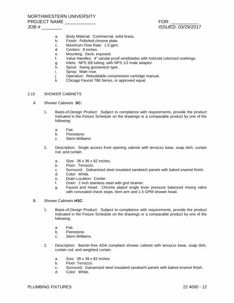
NORTHWESTERN UNIVERSITY PROJECT NAME ____________ FOR: ___________ JOB # ________ ISSUED: 03/29/2017
PLUMBING FIXTURES 22 4000 - 12
a. Body Material: Commercial, solid brass. b. Finish: Polished chrome plate. c. Maximum Flow Rate: 1.5 gpm. d. Centers: 8 inches. e. Mounting: Deck, exposed. f. Valve Handles: 4" vandal proof wristblades with hot/cold colorized markings. g. Inlets: NPS 3/8 tubing, with NPS 1/2 male adaptor. h. Spout: Swing gooseneck type. i. Spray: Male rose. j. Operation: Rebuildable compression cartridge manual. k. Chicago Faucet 786 Series, or approved equal.
2.15 SHOWER CABINETS
A. Shower Cabinets SC:
1. Basis-of-Design Product: Subject to compliance with requirements, provide the product indicated in the Fixture Schedule on the drawings or a comparable product by one of the following:
a. Fiat. b. Florestone. c. Stern-Williams
2. Description: Single access front opening cabinet with terrazzo base, soap dish, curtain rod, and curtain.
a. Size: 36 x 36 x 82 inches. b. Floor: Terrazzo. c. Surround: Galvanized steel insulated sandwich panels with baked enamel finish. d. Color: White. e. Drain Location: Center. f. Drain: 2 inch stainless steel with grid strainer. g. Faucet and Head: Chrome plated single lever pressure balanced mixing valve
with concealed check stops, bent arm and 1.5 GPM shower head.
B. Shower Cabinets HSC:
1. Basis-of-Design Product: Subject to compliance with requirements, provide the product indicated in the Fixture Schedule on the drawings or a comparable product by one of the following:
a. Fiat. b. Florestone. c. Stern-Williams.
2. Description: Barrier-free ADA compliant shower cabinet with terrazzo base, soap dish, curtain rod, and weighted curtain.
a. Size: 39 x 39 x 82 inches. b. Floor: Terrazzo. c. Surround: Galvanized steel insulated sandwich panels with baked enamel finish. d. Color: White.

NORTHWESTERN UNIVERSITY PROJECT NAME ____________ FOR: ___________ JOB # ________ ISSUED: 03/29/2017
PLUMBING FIXTURES 22 4000 - 13
e. Drain Location: Center. f. Drain: 2 inch stainless steel with grid strainer. g. Faucet: Chrome plated single lever pressure balanced mixing valve with
concealed check stops. h. ADA Options:
1) Horizontal corner and vertical stainless steel grab bars. 2) Folding wheelchair transfer seat. 3) Wall hung shower head with 24 inch slide bar, stainless steel hose, and
inline vacuum breaker.
i. Seat and Shower Head Locations: As indicated on the drawings.
2.16 SHOWER RECEPTORS
A. Shower Receptors SR:
1. Basis-of-Design Product: Subject to compliance with requirements, provide the product indicated in the Fixture Schedule on the drawings or a comparable product by one of the following:
a. Fiat. b. Florestone. c. Stern-Williams.
2. Description: Precast-terrazzo base for field built shower walls.
a. Type: Standard with 4 inch high shoulders and rabbets where called for in schedule on the drawings.
b. Size: 36 x36 inches. c. Color: White. d. Drain: Cast-in stainless steel 2 inch drain body with removable grid strainer. e. Drain Location: Center.
B. Shower Receptors HSR:
1. Basis-of-Design Product: Subject to compliance with requirements, provide the product indicated in the Fixture Schedule on the drawings or a comparable product by one of the following:
a. Fiat. b. Florestone. c. Stern-Williams.
2. Description: Wheelchair accessible Precast-terrazzo base for field built shower walls.
a. Type: ADA compliant with 4 inch high shoulders on three sides and entrance arranged for 2” floor depression.
b. Size: 36 x36 inches. c. Color: White. d. Drain: Cast-in stainless steel 2 inch drain body with removable strainer. e. Drain Location: Center.
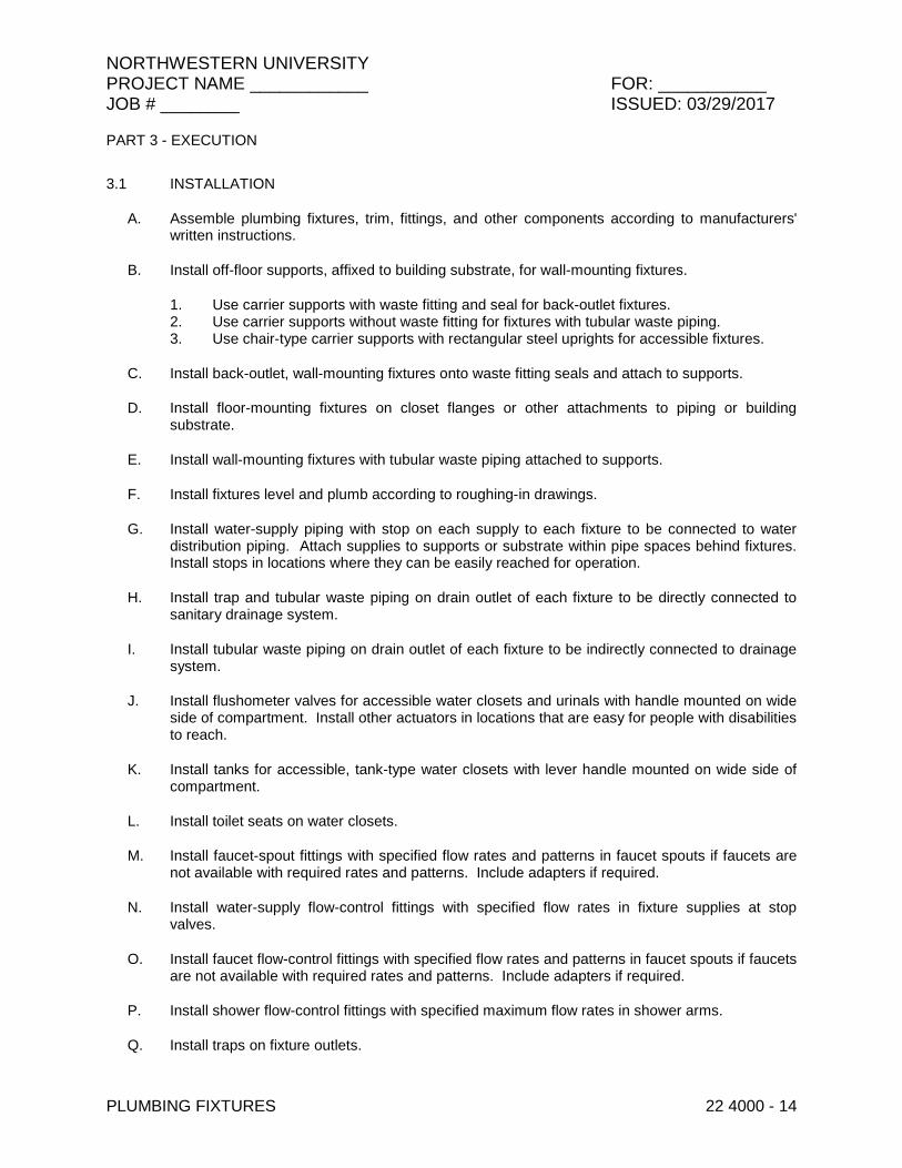
NORTHWESTERN UNIVERSITY PROJECT NAME ____________ FOR: ___________ JOB # ________ ISSUED: 03/29/2017
PLUMBING FIXTURES 22 4000 - 14
PART 3 - EXECUTION
3.1 INSTALLATION
A. Assemble plumbing fixtures, trim, fittings, and other components according to manufacturers' written instructions.
B. Install off-floor supports, affixed to building substrate, for wall-mounting fixtures.
1. Use carrier supports with waste fitting and seal for back-outlet fixtures. 2. Use carrier supports without waste fitting for fixtures with tubular waste piping. 3. Use chair-type carrier supports with rectangular steel uprights for accessible fixtures.
C. Install back-outlet, wall-mounting fixtures onto waste fitting seals and attach to supports.
D. Install floor-mounting fixtures on closet flanges or other attachments to piping or building substrate.
E. Install wall-mounting fixtures with tubular waste piping attached to supports.
F. Install fixtures level and plumb according to roughing-in drawings.
G. Install water-supply piping with stop on each supply to each fixture to be connected to water distribution piping. Attach supplies to supports or substrate within pipe spaces behind fixtures. Install stops in locations where they can be easily reached for operation.
H. Install trap and tubular waste piping on drain outlet of each fixture to be directly connected to sanitary drainage system.
I. Install tubular waste piping on drain outlet of each fixture to be indirectly connected to drainage system.
J. Install flushometer valves for accessible water closets and urinals with handle mounted on wide side of compartment. Install other actuators in locations that are easy for people with disabilities to reach.
K. Install tanks for accessible, tank-type water closets with lever handle mounted on wide side of compartment.
L. Install toilet seats on water closets.
M. Install faucet-spout fittings with specified flow rates and patterns in faucet spouts if faucets are not available with required rates and patterns. Include adapters if required.
N. Install water-supply flow-control fittings with specified flow rates in fixture supplies at stop valves.
O. Install faucet flow-control fittings with specified flow rates and patterns in faucet spouts if faucets are not available with required rates and patterns. Include adapters if required.
P. Install shower flow-control fittings with specified maximum flow rates in shower arms.
Q. Install traps on fixture outlets.

NORTHWESTERN UNIVERSITY PROJECT NAME ____________ FOR: ___________ JOB # ________ ISSUED: 03/29/2017
PLUMBING FIXTURES 22 4000 - 15
1. Exception: Omit trap on fixtures with integral traps. 2. Exception: Omit trap on indirect wastes, unless otherwise indicated.
R. Install escutcheons at piping wall and ceiling penetrations in exposed, finished locations and within cabinets and millwork. Use deep-pattern escutcheons if required to conceal protruding fittings. Escutcheons are specified in Division 22 Section "Escutcheons for Plumbing Piping."
S. Seal joints between fixtures and walls, floors, and countertops using sanitary-type, one-part, mildew-resistant silicone sealant. Match sealant color to fixture color. Sealants are specified in Division 07 Section "Joint Sealants."
3.2 CONNECTIONS
A. Piping installation requirements are specified in other Division 22 Sections. Drawings indicate general arrangement of piping, fittings, and specialties.
B. Connect fixtures with water supplies, stops, and risers, and with traps, soil, waste, and vent piping. Use size fittings required to match fixtures.
C. Ground equipment according to Division 26 Section "Grounding and Bonding for Electrical Systems."
D. Connect wiring according to Division 26 Section "Low-Voltage Electrical Power Conductors and Cables."
3.3 FIELD QUALITY CONTROL
A. Verify that installed plumbing fixtures are categories and types specified for locations where installed.
B. Check that plumbing fixtures are complete with trim, faucets, fittings, and other specified components.
C. Inspect installed plumbing fixtures for damage. Replace damaged fixtures and components.
D. Test installed fixtures after water systems are pressurized for proper operation. Replace malfunctioning fixtures and components, then retest. Repeat procedure until units operate properly.
E. Install fresh batteries in sensor-operated mechanisms.
3.4 PROTECTION
A. Provide protective covering for installed fixtures and fittings.
B. Do not allow use of plumbing fixtures for temporary facilities unless approved in writing by Owner.
END OF SECTION 22 4000
NORTHWESTERN UNIVERSITY PROJECT NAME ____________ FOR: ___________ JOB # ________ ISSUED: 03/29/2017
EMERGENCY PLUMBING FIXTURES 22 4500 - 1
SECTION 22 4500 - EMERGENCY PLUMBING FIXTURES
PART 1 - GENERAL
1.1 RELATED DOCUMENTS
A. Drawings and general provisions of the Contract, including General and Supplementary Conditions and Division 01 Specification Sections, apply to this Section.
1.2 SUMMARY
A. Section Includes:
1. Emergency showers. 2. Eye/face wash equipment. 3. Water-tempering equipment.
1.3 DEFINITIONS
A. Accessible Fixture: Emergency plumbing fixture that can be approached, entered, and used by people with disabilities.
B. Plumbed Emergency Plumbing Fixture: Fixture with fixed, potable-water supply.
C. Tepid: Moderately warm, between 60 – 100° F.
1.4 ACTION SUBMITTALS
A. Product Data: For each type of product indicated. Include flow rates and capacities, furnished specialties, and accessories.
1.5 INFORMATIONAL SUBMITTALS
A. Product Certificates: Submit certificates of performance testing specified in "Source Quality Control" Article.
B. Field quality-control test reports.
1.6 CLOSEOUT SUBMITTALS
A. Operation and Maintenance Data: For emergency plumbing fixtures to include in operation and maintenance manuals.
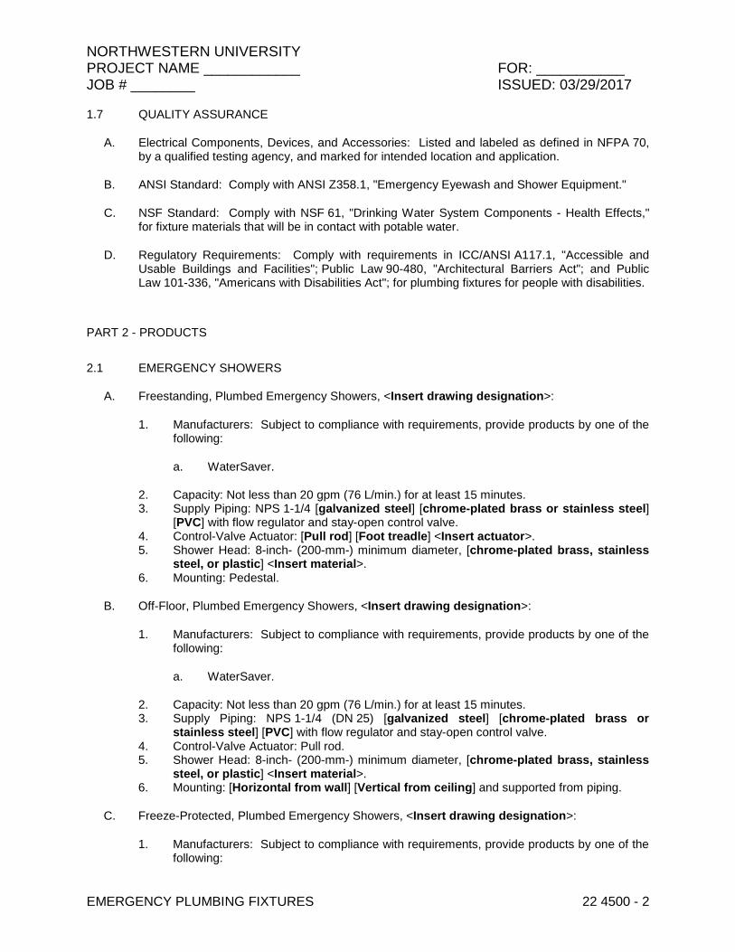
NORTHWESTERN UNIVERSITY PROJECT NAME ____________ FOR: ___________ JOB # ________ ISSUED: 03/29/2017
EMERGENCY PLUMBING FIXTURES 22 4500 - 2
1.7 QUALITY ASSURANCE
A. Electrical Components, Devices, and Accessories: Listed and labeled as defined in NFPA 70, by a qualified testing agency, and marked for intended location and application.
B. ANSI Standard: Comply with ANSI Z358.1, "Emergency Eyewash and Shower Equipment."
C. NSF Standard: Comply with NSF 61, "Drinking Water System Components - Health Effects," for fixture materials that will be in contact with potable water.
D. Regulatory Requirements: Comply with requirements in ICC/ANSI A117.1, "Accessible and Usable Buildings and Facilities"; Public Law 90-480, "Architectural Barriers Act"; and Public Law 101-336, "Americans with Disabilities Act"; for plumbing fixtures for people with disabilities.
PART 2 - PRODUCTS
2.1 EMERGENCY SHOWERS
A. Freestanding, Plumbed Emergency Showers, <Insert drawing designation>:
1. Manufacturers: Subject to compliance with requirements, provide products by one of the following:
a. WaterSaver.
2. Capacity: Not less than 20 gpm (76 L/min.) for at least 15 minutes. 3. Supply Piping: NPS 1-1/4 [galvanized steel] [chrome-plated brass or stainless steel]
[PVC] with flow regulator and stay-open control valve. 4. Control-Valve Actuator: [Pull rod] [Foot treadle] <Insert actuator>. 5. Shower Head: 8-inch- (200-mm-) minimum diameter, [chrome-plated brass, stainless
steel, or plastic] <Insert material>. 6. Mounting: Pedestal.
B. Off-Floor, Plumbed Emergency Showers, <Insert drawing designation>:
1. Manufacturers: Subject to compliance with requirements, provide products by one of the following:
a. WaterSaver.
2. Capacity: Not less than 20 gpm (76 L/min.) for at least 15 minutes. 3. Supply Piping: NPS 1-1/4 (DN 25) [galvanized steel] [chrome-plated brass or
stainless steel] [PVC] with flow regulator and stay-open control valve. 4. Control-Valve Actuator: Pull rod. 5. Shower Head: 8-inch- (200-mm-) minimum diameter, [chrome-plated brass, stainless
steel, or plastic] <Insert material>. 6. Mounting: [Horizontal from wall] [Vertical from ceiling] and supported from piping.
C. Freeze-Protected, Plumbed Emergency Showers, <Insert drawing designation>:
1. Manufacturers: Subject to compliance with requirements, provide products by one of the following:

NORTHWESTERN UNIVERSITY PROJECT NAME ____________ FOR: ___________ JOB # ________ ISSUED: 03/29/2017
EMERGENCY PLUMBING FIXTURES 22 4500 - 3
a. WaterSaver.
2. Capacity: Not less than 20 gpm (76 L/min.) for at least 15 minutes. 3. Supply Piping: NPS 1-1/4 (DN 32) galvanized steel with flow regulator and stay-open
control valve. 4. Control-Valve Actuator: Pull rod. 5. Shower Head: 8-inch- (200-mm-) minimum diameter, [chrome-plated brass, stainless
steel, or plastic] <Insert material>. 6. Heating System: [120] [240]-V ac electric, and insulation with protective jacket. 7. Mounting: Pedestal.
2.2 EYE/FACE WASH EQUIPMENT
A. Standard, Wall-Mounted, Plumbed, Eye/Drench Hose Wash Units, <Insert drawing designation>:
1. Manufacturers: Subject to compliance with requirements, provide products by one of the following:
a. WaterSaver.
2. Capacity: Not less than 3.0 gpm (11.4 L/min.) for at least 15 minutes. 3. Supply Piping: NPT 3/8” male swivel-type inlet, chrome-plated brass or stainless steel
with flow regulator and stay-open control valve. 4. Drench Hose: Hand-held spray head with squeeze-handle actuation, locking clip, and 8
ft. stainless steel hose. 5. Spray-Head Assembly: Two receptor-mounted spray heads with dust covers. 6. Mounting: Wall bracket. 7. Special Construction: Comply with ANSI Z358.1-2014.
2.3 WATER-TEMPERING EQUIPMENT
A. Hot- and Cold-Water, Water-Tempering Equipment, TMV-2:
1. Manufacturers: Subject to compliance with requirements, provide products by one of the following:
a. WaterSaver.
2. Description: Factory-fabricated equipment with thermostatic mixing valve.
a. AP3600 Thermostatic Mixing Valve: Designed to provide 85 deg F (29 deg C) tepid, potable water at emergency plumbing fixtures, to maintain temperature at plus or minus 5 deg F (3 deg C) throughout required 15-minute test period, and in case of unit failure to continue cold-water flow, with union connections, controls, metal piping, and corrosion-resistant enclosure. ANSI 358.1-2014 compliant.
b. Supply Connections: For hot and cold water.
2.4 SOURCE QUALITY CONTROL
A. Certify performance of emergency plumbing fixtures by independent testing organization acceptable to authorities having jurisdiction.
NORTHWESTERN UNIVERSITY PROJECT NAME ____________ FOR: ___________ JOB # ________ ISSUED: 03/29/2017
EMERGENCY PLUMBING FIXTURES 22 4500 - 4
PART 3 - EXECUTION
3.1 EXAMINATION
A. Examine roughing-in for water and waste piping systems to verify actual locations of piping connections before plumbed emergency plumbing fixture installation.
B. Proceed with installation only after unsatisfactory conditions have been corrected.
3.2 EMERGENCY PLUMBING FIXTURE INSTALLATION
A. Assemble emergency plumbing fixture piping, fittings, control valves, and other components.
B. Install fixtures level and plumb.
C. Fasten fixtures to substrate.
D. Install shutoff valves in water-supply piping to fixtures. Use ball, gate, or globe valve if specific type valve is not indicated. Install valves chained or locked in open position if permitted. Install valves in locations where they can easily be reached for operation. Comply with requirements for valves specified in Section 220523 "General-Duty Valves for Plumbing Piping."
1. Exception: Omit shutoff valve on supply to emergency equipment if prohibited by authorities having jurisdiction.
E. Install dielectric fitting in supply piping to emergency equipment if piping and equipment connections are made of different metals. Comply with requirements for dielectric fittings specified in Section 221116 "Domestic Water Piping."
F. Install thermometers in supply and outlet piping connections to water-tempering equipment. Comply with requirements for thermometers specified in Section 220519 "Meters and Gages for Plumbing Piping."
G. Install trap and waste piping on drain outlet of emergency equipment receptors that are indicated to be directly connected to drainage system. Comply with requirements for waste piping specified in Section 221316 "Sanitary Waste and Vent Piping."
H. Install indirect waste piping on drain outlet of emergency equipment receptors that are indicated to be indirectly connected to drainage system. Comply with requirements for waste piping specified in Section 221316 "Sanitary Waste and Vent Piping."
I. Install escutcheons on piping wall and ceiling penetrations in exposed, finished locations. Comply with requirements for escutcheons specified in Section 220518 "Escutcheons for Plumbing Piping."
J. Fill self-contained fixtures with flushing fluid.
3.3 CONNECTIONS
A. Connect cold-water-supply piping to plumbed emergency plumbing fixtures not having water-tempering equipment. Comply with requirements for cold-water piping specified in Section 221116 "Domestic Water Piping."
NORTHWESTERN UNIVERSITY PROJECT NAME ____________ FOR: ___________ JOB # ________ ISSUED: 03/29/2017
EMERGENCY PLUMBING FIXTURES 22 4500 - 5
B. Connect hot- and cold-water-supply piping to hot- and cold-water, water-tempering equipment. Connect output from water-tempering equipment to emergency plumbing fixtures. Comply with requirements for hot- and cold-water piping specified in Section 221116 "Domestic Water Piping."
C. Directly connect emergency plumbing fixture receptors with trapped drain outlet to sanitary waste and vent piping. Comply with requirements for waste piping specified in Section 221316 "Sanitary Waste and Vent Piping."
D. Indirectly connect emergency plumbing fixture receptors without trapped drain outlet to sanitary waste or storm drainage piping.
E. Where installing piping adjacent to emergency plumbing fixtures, allow space for service and maintenance of fixtures.
3.4 IDENTIFICATION
A. Install equipment nameplates or equipment markers on emergency plumbing fixtures and equipment and equipment signs on water-tempering equipment. Comply with requirements for identification materials specified in Section 220553 "Identification for Plumbing Piping and Equipment."
3.5 FIELD QUALITY CONTROL
A. Mechanical-Component Testing: After plumbing connections have been made, test for compliance with requirements. Initial test shall be performed in the presence of a plumbing shop representative in FMO. Verify ability to achieve indicated capacities.
B. Tests and Inspections:
1. Perform each visual and mechanical inspection. 2. Leak Test: After installation, charge system and test for leaks. Repair leaks and retest
until no leaks exist. 3. Operational Test: After electrical circuitry has been energized, start units to confirm
proper unit operation. 4. Test and adjust controls and safeties. Replace damaged and malfunctioning controls
and equipment.
C. Emergency plumbing fixtures and water-tempering equipment will be considered defective if they do not pass tests and inspections.
D. Prepare test and inspection reports.
3.6 ADJUSTING
A. Adjust or replace fixture flow regulators for proper flow.
B. Adjust equipment temperature settings.
END OF SECTION 22 4500
NORTHWESTERN UNIVERSITY PROJECT NAME ____________ FOR: ___________ JOB # ________ ISSUED: 03/29/2017
EMERGENCY PLUMBING FIXTURES 22 4500 - 6
THIS PAGE IS INTENTIONALLY BLANK