DIVISION 22 – PLUMBING Section Title Number … · DIVISION 22 – PLUMBING Section Title Number...
25
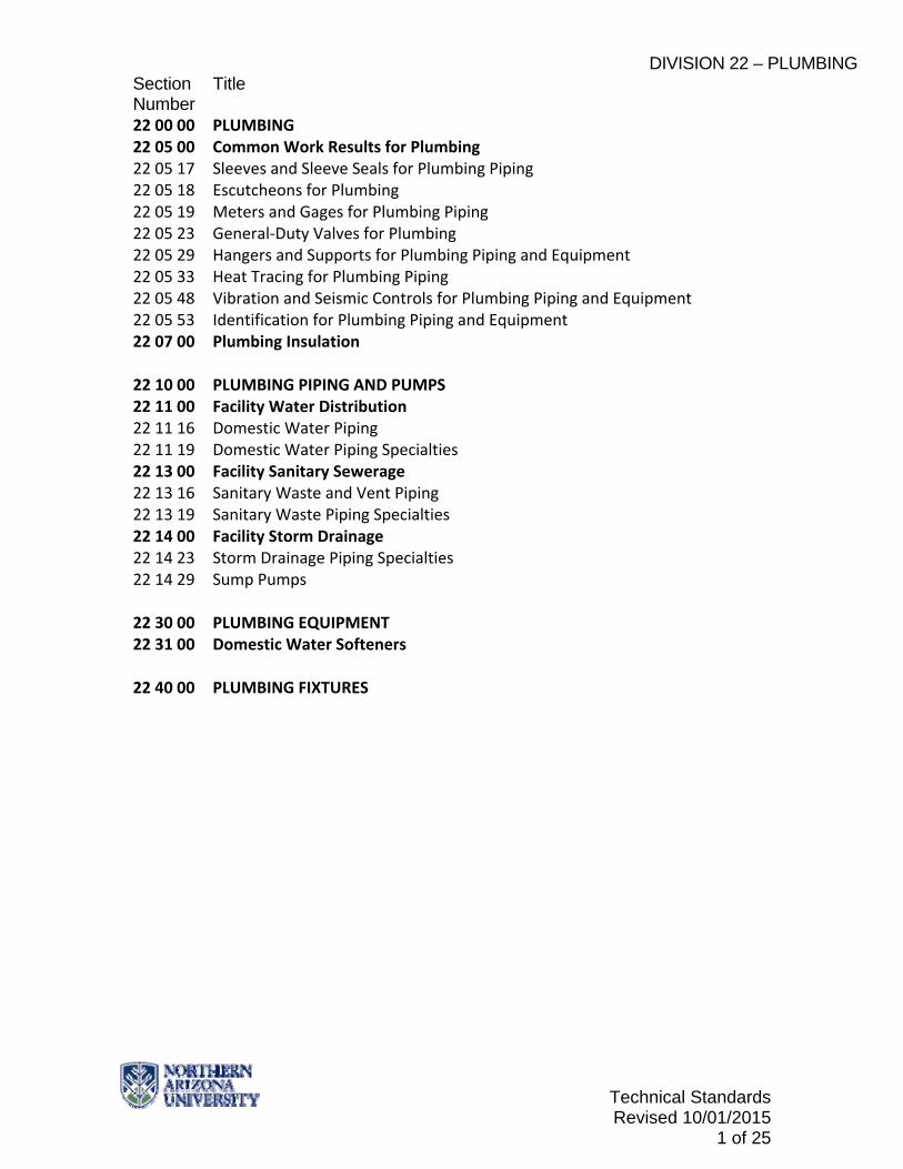
DIVISION 22 – PLUMBING Section Title Number Technical Standards Revised 10/01/2015 1 of 25 22 00 00 PLUMBING 22 05 00 Common Work Results for Plumbing 22 05 17 Sleeves and Sleeve Seals for Plumbing Piping 22 05 18 Escutcheons for Plumbing 22 05 19 Meters and Gages for Plumbing Piping 22 05 23 General‐Duty Valves for Plumbing 22 05 29 Hangers and Supports for Plumbing Piping and Equipment 22 05 33 Heat Tracing for Plumbing Piping 22 05 48 Vibration and Seismic Controls for Plumbing Piping and Equipment 22 05 53 Identification for Plumbing Piping and Equipment 22 07 00 Plumbing Insulation 22 10 00 PLUMBING PIPING AND PUMPS 22 11 00 Facility Water Distribution 22 11 16 Domestic Water Piping 22 11 19 Domestic Water Piping Specialties 22 13 00 Facility Sanitary Sewerage 22 13 16 Sanitary Waste and Vent Piping 22 13 19 Sanitary Waste Piping Specialties 22 14 00 Facility Storm Drainage 22 14 23 Storm Drainage Piping Specialties 22 14 29 Sump Pumps 22 30 00 PLUMBING EQUIPMENT 22 31 00 Domestic Water Softeners 22 40 00 PLUMBING FIXTURES
Transcript of DIVISION 22 – PLUMBING Section Title Number … · DIVISION 22 – PLUMBING Section Title Number...
DIVISION 22 – PLUMBING Section Title Number
Technical Standards Revised 10/01/2015
1 of 25
22 00 00 PLUMBING 22 05 00 Common Work Results for Plumbing 22 05 17 Sleeves and Sleeve Seals for Plumbing Piping 22 05 18 Escutcheons for Plumbing 22 05 19 Meters and Gages for Plumbing Piping 22 05 23 General‐Duty Valves for Plumbing 22 05 29 Hangers and Supports for Plumbing Piping and Equipment 22 05 33 Heat Tracing for Plumbing Piping 22 05 48 Vibration and Seismic Controls for Plumbing Piping and Equipment 22 05 53 Identification for Plumbing Piping and Equipment 22 07 00 Plumbing Insulation 22 10 00 PLUMBING PIPING AND PUMPS 22 11 00 Facility Water Distribution 22 11 16 Domestic Water Piping 22 11 19 Domestic Water Piping Specialties 22 13 00 Facility Sanitary Sewerage 22 13 16 Sanitary Waste and Vent Piping 22 13 19 Sanitary Waste Piping Specialties 22 14 00 Facility Storm Drainage 22 14 23 Storm Drainage Piping Specialties 22 14 29 Sump Pumps 22 30 00 PLUMBING EQUIPMENT 22 31 00 Domestic Water Softeners 22 40 00 PLUMBING FIXTURES

DIVISION 22 – PLUMBING Section Title Number
Technical Standards Revised 10/01/2015
2 of 25
22 00 00 PLUMBING
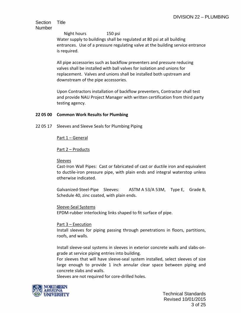
Description See Division 1 for code compliance requirements. All new buildings and building expansion projects shall utilize the campus potable water and sanitary sewer systems see division 33 for utility standards. Building potable water and sanitary sewer requirement shall be calculated at the programming or schematic design submittals to assure adequate services are available at anticipated connection points. Refinement is expected as design progresses and shall be finalized at the design development stage, with final interconnection requirements identified. All backflow protection and water supply and sewage connections will comply with the City of Flagstaff building codes and amendments. Currently, there are seven (7) connections to the City of Flagstaff municipal water supply system. All service and supply systems, including, but not limited to, domestic water and waste, shall be sized for peak demand throughout the project and shall be sized as far back as the main meter or central distribution system. The adequacy of any central distribution system to carry all added peak loads shall be determined, and no loads shall be connected to any such system that is determined to be undersized. The use of any electrical source domestic hot water heaters shall not be considered unless a minimum of 20 year life cycle cost analysis of all alternatives is performed. Electrical source equipment shall not be specified unless it is proven to be the most cost effective for the 20 year life cycle. The determination of energy costs must include both consumption and demand charges. Transformer Vaults and Electrical Rooms shall have no water, waste, storm drain, nor any other pipe conveying water (except fire sprinkler systems required for the vault). A statement shall be included in the specifications that all pipes, fittings and valves shall be made in the USA. Water main line pressures experienced at NAU are: Day hours 100 psi
DIVISION 22 – PLUMBING Section Title Number
Technical Standards Revised 10/01/2015
3 of 25
Night hours 150 psi Water supply to buildings shall be regulated at 80 psi at all building entrances. Use of a pressure regulating valve at the building service entrance is required. All pipe accessories such as backflow preventers and pressure reducing valves shall be installed with ball valves for isolation and unions for replacement. Valves and unions shall be installed both upstream and downstream of the pipe accessories. Upon Contractors installation of backflow preventers, Contractor shall test and provide NAU Project Manager with written certification from third party testing agency.
22 05 00 Common Work Results for Plumbing 22 05 17 Sleeves and Sleeve Seals for Plumbing Piping
Part 1 – General Part 2 – Products
Sleeves Cast‐Iron Wall Pipes: Cast or fabricated of cast or ductile iron and equivalent to ductile‐iron pressure pipe, with plain ends and integral waterstop unless otherwise indicated. Galvanized‐Steel‐Pipe Sleeves: ASTM A 53/A 53M, Type E, Grade B, Schedule 40, zinc coated, with plain ends.
Sleeve‐Seal Systems EPDM‐rubber interlocking links shaped to fit surface of pipe.
Part 3 – Execution Install sleeves for piping passing through penetrations in floors, partitions, roofs, and walls. Install sleeve‐seal systems in sleeves in exterior concrete walls and slabs‐on‐grade at service piping entries into building. For sleeves that will have sleeve‐seal system installed, select sleeves of size large enough to provide 1 inch annular clear space between piping and concrete slabs and walls. Sleeves are not required for core‐drilled holes.

DIVISION 22 – PLUMBING Section Title Number
Technical Standards Revised 10/01/2015
4 of 25
Install sleeves in concrete floors, concrete roof slabs, and concrete walls as new slabs and wall are constructed.
For sleeves in floors of mechanical equipment areas or other wet areas, extend sleeve 2 inches above finished floor level. Install sleeves for pipes passing through interior partitions.
Install sleeves that are large enough to provide 1/4 inch annular clear space between sleeve and pipe or pipe insulation.
Fire‐Barrier Penetrations: Maintain indicated fire rating of walls, partitions, ceilings, and floors at pipe penetrations. Seal pipe penetrations with firestop materials.
22 05 18 Escutcheons for Plumbing
Part 1 – General Part 2 – Products Escutcheons One‐Piece, Cast‐Brass Type with polished, chrome‐plated finish and setscrew fastener.
Floor Plates One‐Piece Floor Plates: Cast‐iron flange with holes for fasteners.
Part 3 – Execution Install escutcheons for piping penetrations of walls, ceilings, and finished floors. Install escutcheons with ID to closely fit around pipe, tube, and insulation of piping and with OD that completely covers opening. Provide escutcheons for new piping at the following locations: Bare Piping at Wall and Floor Penetrations in Finished Spaces Bare Piping at Ceiling Penetrations in Finished Spaces Bare Piping in Unfinished Service Spaces Bare Piping in Equipment Rooms

DIVISION 22 – PLUMBING Section Title Number
Technical Standards Revised 10/01/2015
5 of 25
Provide floor plates for piping penetrations of equipment‐room floors. 22 05 19 Meters and Gages for Plumbing Piping
Part 1 – General Provide data connection for metering. Coordinate requirements with NAU IT. Part 2 – Products
Water Meters Meter shall be Onicon with readability at the unit and remote through the campus EMS system or approved equivalent. Meters will be placed immediately following the main building shutoff. Isolation valves shall be placed downstream of the meter for testing. Backflows and PRVS shall be placed after the meter with a bypass around the assembly. Liquid‐In‐Glass Thermometers Metal‐Case, Industrial‐Style, 9 inch nominal size cast aluminum case, adjustable angle, glass tube with magnifying lens and blue organic liquid, glass window, aluminum stem, . Plus or minus 1 percent of scale range or one scale division, to a maximum of 1.5 percent of scale range Thermowells Pressure‐tight, socket‐type fitting made for insertion into piping tee fitting, copper nickel (90‐10) for use with copper tubing, corrosion resistant steel for use with steel piping, stepped shank, lagging extension for insulated piping and tubing. Heat transfer medium shall be mixture of graphite and glycerin. Metal‐Case, Dial‐Type Pressure Gages Sealed type case, 4‐1/2 inches nominal diameter, bourdon tube, mechanical movement connected to pressure element and pointer, glass window, metal ring, Grade A, plus or minus 1% of middle half scale range. Snubbers Brass; threaded, piston‐type surge‐dampening device. Include extension for use on insulated piping. Provide threaded, brass ball valves at each snubber. Part 3 – Execution Install thermowells with socket extending one‐third of pipe diameter and in vertical position in piping tees. Install valve and snubber in piping for each pressure gage for fluids.
22 05 23 General‐Duty Valves for Plumbing
DIVISION 22 – PLUMBING Section Title Number
Technical Standards Revised 10/01/2015
6 of 25
Part 1 – General
Part 2 – Products The Design Professional shall specify supply valves of domestic quality i.e., Jomar Valve, Milwaukee Manufacturing or approved equivalent. All isolation valves to be ball valves. Domestic, Hot‐ and Cold‐ Water Valves Pipe 2 inches and Smaller Ball Valves: Two piece, full port, brass or bronze with resilient seat, 150 WOG pressure rated. Bronze Swing Check Valves: bronze disc. Pipe 2‐1/2 inces and Larger
Iron Gate Valves: Class 125. Iron Swing Check Valves: Class 250, metal seats. Part 3 – Execution Domestic water systems shall be zoned with shut‐off capability for stacked rooms. Provide isolation valves for each floor and for every bathroom and all water supplied fixture. Install valve stems either vertically up or 45 degrees from vertical, horizontal or 45 degrees up from horizontal. Provide unions at all threaded valve connections.
22 05 29 Hangers and Supports for Plumbing Piping and Equipment Part 1 – General Part 2 – Products
Metal Pipe Hangers and Supports Carbon‐Steel Pipe Hangers and Supports ‐ MSS SP‐58, Types 1 through 58, factory‐fabricated components, continuous‐thread hanger rod, nuts, and washer made of carbon steel.

DIVISION 22 – PLUMBING Section Title Number
Technical Standards Revised 10/01/2015
7 of 25
Stainless‐Steel Pipe Hangers and Supports ‐ MSS SP‐58, Types 1 through 58, factory‐fabricated components, continuous‐thread hanger rod, nuts, and washer made of stainless steel. Copper Pipe Hangers ‐ MSS SP‐58, Types 1 through 58, copper‐coated‐steel, factory‐fabricated components, continuous‐thread hanger rod, nuts, and washer made of copper‐coated steel Trapeze Pipe Hangers MSS SP‐69, Type 59, shop‐ or field‐fabricated pipe‐support assembly made from structural carbon‐steel shapes with MSS SP‐58 carbon‐steel hanger rods, nuts, saddles, and U‐bolts. Thermal Hanger Shield Inserts For Trapeze or Clamped Systems: Insert and shield shall cover entire circumference of pipe. For Clevis or Band Hangers: Insert and shield shall cover lower 180 degrees of pipe. Insert Length: Extend 2 inches beyond sheet metal shield for piping operating below ambient air temperature. Equipment Supports Welded, shop‐ or field‐fabricated equipment support made from structural carbon‐steel shapes. Part 3 – Execution Use carbon‐steel pipe hangers and support and attachments for general service applications. Use stainless‐steel pipe hangers and stainless‐steel attachments for hostile environment applications. Use copper‐plated or stainless steel pipe hangers and copper attachments for copper piping and tubing. Use thermal‐hanger shield inserts for insulated piping and tubing.
22 05 33 Heat Tracing for Plumbing Piping
Part 1 – General Heat tracing for plumbing system is not allowed.

DIVISION 22 – PLUMBING Section Title Number
Technical Standards Revised 10/01/2015
8 of 25
Part 2 – Products Part 3 – Execution
22 05 53 Identification for Plumbing Piping and Equipment
Part 1 – General
Part 2 – Products Equipment Labels
Brass, 0.032 inch minimum thickness, and having predrilled or stamped holes for attachment hardware. Minimum Label Size: 2‐1/2 inches by 3/4 inch Fasteners: Stainless steel rivets fasteners Include equipment's Drawing designation or unique equipment number on each equipment label. For each item of equipment to be labeled, provide tabulated equipment identification number and identify Drawing numbers where equipment is indicated (plans, details, and schedules), plus the Specification Section number and title where equipment is specified. Equipment schedule shall be included in operation and maintenance data. Warning Signs and Labels Multicolor, plastic labels for mechanical engraving, 1/8 inch thick, and having predrilled holes for attachment hardware. Letter color and background color to be determined by NAU Project Manager. Minimum Label Size: 2‐1/2 inches by 3/4 inch Fasteners: Stainless‐steel rivets Label Content: Include caution and warning information, plus emergency notification instructions.

DIVISION 22 – PLUMBING Section Title Number
Technical Standards Revised 10/01/2015
9 of 25
Pipe Labels Self‐Adhesive Pipe Labels: Printed plastic with contact‐type, permanent‐adhesive backing. Pipe Label Contents: Include identification of piping service using same designations or abbreviations as used on Drawings, pipe size, and an arrow indicating flow direction. Flow‐Direction Arrows: Integral with piping system service lettering to accommodate both directions or as separate unit on each pipe label to indicate flow direction. Lettering Size: At least 1‐1/2 inches high. Part 3 – Execution Locate pipe labels where piping is exposed or above accessible ceilings in finished spaces; machine rooms; accessible maintenance spaces such as shafts, tunnels, and plenums; and exterior exposed locations as follows:
Near each valve and control device.
Near each branch connection, excluding short takeoffs for fixtures and terminal units. Where flow pattern is not obvious, mark each pipe at branch.
Near penetrations through walls, floors, ceilings, and inaccessible enclosures.
At access doors, manholes, and similar access points that permit view of concealed piping.
Near major equipment items and other points of origination and termination.
Spaced at maximum intervals of 50 feet along each run. Reduce intervals to 25 feet in areas of congested piping and equipment.
On piping above removable acoustical ceilings. Omit intermediately spaced labels.
Coordinate labeling color coding with NAU Project Manager.

DIVISION 22 – PLUMBING Section Title Number
Technical Standards Revised 10/01/2015
10 of 25
22 07 00 Plumbing Insulation
Part 1 ‐ General Fire‐Test‐Response Characteristics: Insulation and related materials shall have fire‐test‐response characteristics, as determined by testing identical products per ASTM E 84, by a testing and inspecting agency acceptable to authorities having jurisdiction. Factory label insulation and jacket materials and adhesive, mastic, tapes, and cement material containers, with appropriate markings of applicable testing and inspecting agency. Insulation Installed Indoors: Flame‐spread index of 25 or less, and smoke‐developed index of 50 or less. Insulation Installed Outdoors: Flame‐spread index of 75 or less, and smoke‐developed index of 150 or less. Part 2 – Products Products shall not contain asbestos, lead, mercury, or mercury compounds. Provide TrueBro insulation kits for angle stops, drains, P‐traps and supply lines located in ADA compliant bathrooms. Mineral‐Fiber, Preformed Pipe Insulation Type I, 850 degrees F Materials: Mineral or glass fibers bonded with a thermosetting resin. Comply with ASTM C 547, Type I, Grade A, with factory‐applied ASJ‐SSL. Factory Applied Jackets ASJ‐SSL: ASJ with self‐sealing, pressure‐sensitive, acrylic‐based adhesive covered by a removable protective strip; complying with ASTM C 1136, Type I. Field Applied Jackets PVC Jacket: High‐impact‐resistant, UV‐resistant PVC complying with ASTM D 1784, Class 16354‐C; Roll stock ready for shop or field cutting and forming. PVC Jacket Adhesive Compatible with PVC jacket. For indoor applications, use adhesive that has a VOC content of 50 g/L or less when calculated according to 40 CFR 59, Subpart D (EPA Method 24).

DIVISION 22 – PLUMBING Section Title Number
Technical Standards Revised 10/01/2015
11 of 25
Joint Sealants for PVC Jackets For indoor applications, use sealants that have a VOC content of 250 g/L or less when calculated according to 40 CFR 59, Subpart D (EPA Method 24). Part 3 – Execution Insulate pipe elbows using preformed fitting insulation or mitered fittings made from same material and density as adjacent pipe insulation. Insulate tee fittings with preformed fitting insulation or sectional pipe insulation of same material and thickness as used for adjacent pipe. Insulate valves using preformed fitting insulation or sectional pipe insulation of same material, density, and thickness as used for adjacent pipe. Insulate strainers using preformed fitting insulation or sectional pipe insulation of same material, density, and thickness as used for adjacent pipe. Insulate flanges and unions using a section of oversized preformed pipe insulation. Overlap adjoining pipe insulation by not less than two times the thickness of pipe insulation, or one pipe diameter, whichever is thicker. Stencil or label the outside insulation jacket of each union with the word "UNION." Match size and color of pipe labels. Insulate instrument connections for thermometers, pressure gages, pressure temperature taps, test connections, flow meters, sensors, switches, and transmitters on insulated pipes, vessels, and equipment. PVC jackets shall be installed with 1 inch overlap at longitudinal seams and end joints; for horizontal applications. Apply two continuous beads of adhesive to seams and joints, one bead under lap and the finish bead along seam and joint edge. Domestic Cold, Hot, Hot and Recirculated Hot Water Insulation shall be Mineral‐Fiber, Preformed Pipe Insulation, Type I, 1 inch thick. Install PVC jackets, 20 mils thick at pipe fitting.
**END OF SECTION**

DIVISION 22 – PLUMBING Section Title Number
Technical Standards Revised 10/01/2015
12 of 25
22 10 00 PLUMBING PIPING AND PUMPS 22 11 00 Facility Water Distribution 22 11 16 Domestic Water Piping
Part 1 – General Plumbing lines shall not be located in outside walls, unheated attics, basements, or other unconditioned areas without specific written approval from Capital Assets and Services.
Maximum water velocity in pipes shall be 7 fps. Part 2 – Products Domestic water lines shall be a minimum of Type L copper.
Copper pressure‐seal fittings and pressure‐sealed joints shall not be specified.
Ductile iron pipe with grooved joints shall not be specified. CPVC or PVC pipe shall not be specified.
PEX tube shall not be specified. Dielectric Fittings General Requirements: Assembly of copper alloy and ferrous materials or ferrous material body with separating nonconductive insulating material suitable for system fluid, pressure, and temperature. Dielectric Unions Pressure Rating: 150 psig at 180 degrees F. End Connections: Solder‐joint copper alloy and threaded ferrous.
Dielectric Flanges Factory‐fabricated, bolted, companion‐flange assembly. Pressure Rating: 150 psig. End Connections: Solder‐joint copper alloy and threaded ferrous; threaded solder‐joint copper alloy and threaded ferrous. Dielectric Nipples Electroplated steel nipple complying with ASTM F 1545. Pressure Rating: 300 psig at 225 degrees F

DIVISION 22 – PLUMBING Section Title Number
Technical Standards Revised 10/01/2015
13 of 25
End Connections: Male threaded. Lining: Inert and noncorrosive, propylene.
Domestic Water Piping Located Under Building Slab Pipe 2.5 inches and Smaller: Soft copper tube, ASTM B 88, Type K; and brazed joints.
Pipe 3 inches and Larger: Soft copper tube, ASTM B 88, Type K; and brazed joints. Mechanical‐joint, ductile‐iron pipe; standard‐ or compact‐ pattern mechanical‐joint fittings; and mechanical joints. Domestic Water Piping Located Aboveground Pipe 2 inches and Smaller: Hard copper tube, ASTM B 88, Type L; wrought copper solder‐joint fittings; and soldered joints.
Pipe 2‐1/2 inches to 4 inches: Hard copper tube, ASTM B 88, Type L; wrought‐ copper solder‐joint fittings; and brazed joints. Pipe 5 inches to 8 inches: No groove lock fittings allowed. Hard copper tube, ASTM B 88, Type L; wrought‐ copper solder‐joint fittings; and brazed joints.
Part 3 – Execution Domestic water system shall be flushed, checked for leaks, corrosion inhibitors added where applicable, disinfected for domestic water and otherwise made ready for acceptance. Notice of such tests will be given to Facility Services and Coconino County Health Department. Domestic water supply systems shall be charged with a sterilization solution conforming to Federal Specification 0‐8‐441, Grade D (chlorine). Solution shall remain in the system for 24 Hours. Comply with requirements of the third party testing company. System shall then be flushed and test results provided to the Project or Construction Manager. Dielectric Fitting Installation Install dielectric fittings in piping at connections of dissimilar metal piping and tubing.

DIVISION 22 – PLUMBING Section Title Number
Technical Standards Revised 10/01/2015
14 of 25
Dielectric Fittings for 2 inches and Smaller: Use dielectric unions or nipples. Dielectric Fittings for 2‐1/2 inches to 4 inches: Use dielectric flanges.
22 11 19 Domestic Water Piping Specialties
Part 1 – General Plastic Piping Components shall not be specified.
Quality Assurance Drinking Water System Components shall comply with NSF 61. Part 2 – Products Vacuum Breakers Pipe‐applied, atmospheric‐type. Backflow Preventers Intermediate atmospheric‐vent backflow preventers shall not be specified.
Reduced‐Pressure‐Principle Backflow Preventers Bronze body for 2 inches and smaller Cast iron with interior lining complying with AWWA C550 or that is FDA approved for 2‐1/2 inches and larger. Backflow preventers shall be listed as an approved assembly by the University of Southern California Foundation for Cross Connection Control and Hydraulic Research. Backflow preventers shall be Wilkins 975. Water Pressure‐Reducing Valves Bronze body for 2 inches and smaller. Cast iron body with interior lining complying with AWWA C550 or that is FDA approved for 2‐1/2 inches and 3 inches. Temperature‐Actuated Water Mixing Valves Primary, Thermostatic, Water Mixing Valves: Recessed cabinet mounting type with union inlets and outlet. Manifold, Thermostatic, Water‐Mixing‐Valve Assemblies: Recessed

DIVISION 22 – PLUMBING Section Title Number
Technical Standards Revised 10/01/2015
15 of 25
mounting cabinet‐type, valves parallel arrangement. Strainers for Domestic Water Piping Bronze body for 2 inches and smaller. Cast iron body with interior lining complying with AWWA C550 or FDA‐approved, epoxy coating for 2‐1/2 inches and larger. Stainless steel screen with round perforations. Hose‐end drain valve.
Outlet Boxes Clothes Washer Outlet Boxes: Enameled‐steel or epoxy‐painted‐steel box and faceplate. Icemaker Outlet Boxes: Enameled‐steel or epoxy‐painted‐steel box and faceplate. Hose Bibbs Include integral vacuum breaker. Keyless in public areas.
Wall Hydrants Wall hydrant Nonfreeze, concealed outlet. Automatic‐draining, anti‐backflow type. Provide one operating key. Wall hydrants shall be Woodford Model 67. Part 3 – Execution All cleanouts, meters, controllers, valves, etc. in any green belt area must be installed in boxes with removable lids. All boxes shall be concrete, flush to surface at grade. Design Professional shall specify testing on all backflow preventers. Testing shall be performed by a certified tester and results shall be submitted in writing to Facility Services. Backflow preventers and testing by certified authority per R18‐4‐232.
DIVISION 22 – PLUMBING Section Title Number
Technical Standards Revised 10/01/2015
16 of 25
The contractor shall perform initial testing and certification.
Backflow preventer shall be installed as close as practicable to the service connection.
Install backflow preventer in the building mechanical room. Install trap seal primer valves with valve outlet piping pitched down toward drain trap a minimum of 1/8 inch per foot (1 percent) and connect to floor drain body, trap, or inlet fitting. Trap primers must be accessible. Install isolation valve and unions for each trap primer. Install cleanouts in drain piping as required by the plumbing code and at each sewer main change in direction of 90 degrees, at minimum intervals of 50 feet for piping 4 inches and smaller and 100 foot minimum intervals for larger piping. Install cleanouts at the base of each vertical soil or waste stack. Exterior cleanouts shall be two‐way. Backflow preventer shall be installed as close as practicable to the service connection. Install backflow preventer in the building mechanical room. Install trap seal primer valves with valve outlet piping pitched down toward drain trap a minimum of 1/8 inch per foot (1 percent) and connect to floor drain body, trap, or inlet fitting. Trap primers must be accessible. Install isolation valve and unions for each trap primer. Install cleanouts in drain piping as required by the plumbing code and at each sewer main change in direction of 90 degrees, at minimum intervals of 50 feet for piping 4 inches and smaller and 100 foot minimum intervals for larger piping. Install cleanouts at the base of each vertical soil or waste stack. Exterior cleanouts shall be two‐way. Cleanouts shall be bullhorn type Extend wall cleanouts out to finished wall. Reduced pressure backflow preventers shall be installed at service into building, at connections between potable and non‐potable water systems.

DIVISION 22 – PLUMBING Section Title Number
Technical Standards Revised 10/01/2015
17 of 25
Double check backflow prevention assemblies shall be installed at applications such as photo labs, etc.
Anti‐siphon, pressure type vacuum breakers shall be installed at connection to irrigation systems. Install strainer on building potable water supply after building shut‐off and upstream of backflow preventer. Install ball valves with hose end threads for system drains. Water hammer arrestors to be sized according to number of fixture units and installed between last 2 fixtures of branch with quick closing devices (e.g. flush valves, solenoid valves, etc.). Water hammer arresters shall be provided on both hot and cold water lines serving fixtures and equipment using flush‐o‐meter valves or quick‐closing valves. One water hammer arrestor may serve more than one fixture. These devices must be installed in the upright position. Where utility access has not been provided, access panels shall be provided for access to maintain these devices. Provide isolation valves for all water hammers (separate from fixture shut‐off valves). Specify totalizing meters for domestic water for all privately owned facilities on the NAU campus.
22 13 00 Facility Sanitary Sewerage 22 13 16 Sanitary Waste and Vent Piping
Part 1 – General Part 2 – Products Sovent stack and fittings shall not be used above ground. Materials Provide Fernco coupling for transition between below grade and above grade piping. PVC, solvent weld fittings and pipe are acceptable for underground service. Hubless, cast‐iron soil pipe, service weight, and cast‐iron hubless piping

DIVISION 22 – PLUMBING Section Title Number
Technical Standards Revised 10/01/2015
18 of 25
couplings with minimum 4 each stainless steel clamps for above grade piping.
Acid Resistant Waste and Vent (laboratories) ‐ Schedule 40 flame retardant polypropylene using socket weld fittings and electric fusion joining system. Specify Orion acid waste type system. Part 3 – Execution Smaller than 4 inches drain piping: Install sanitary building drain piping at a minimum slope of 1/4 inch per foot. 4 inches and larger drain piping: Install sanitary building drain piping at a minimum slope of 1/8 inch per foot. Install laboratory waste piping in an accessible pipeway. Vents shall extend full size through roof and shall project 12 inches (minimum) above the roof. Use 4 lb lead jack, rolled and secured on vent stack with minimum 22 gauge chrome thickness clamp. All waste piping exposed below sinks or fixtures shall be plastic.
22 13 19 Sanitary Waste Piping Specialties
Part 1 – General Floor drains and sinks shall be precisely located on drawings. The location shall be such as to minimize length of drain pipes lying on the floor. All floor drains shall be supplied with trap primers. Part 2 – Products Floor Drains: Cast iron body. Floor drains for use as area drains in exterior slab on grade shall be furnished with anchor flange. Inlet fittings shall be cast iron with threaded inlet and threaded or spigot outlet and trap seal primer valve connection. Airgap fittings shall be cast iron or cast bronze, with fixed air gap, inlet for drain pipe or tube, and threaded or spigot outlet. Provide seepage flange at all floor drains in suspended slabs. Provide trap primers at all floor drains. Provide tapped trap on floor sinks and floor drains. Floor sinks: Acid resistant enamel coated cast iron. Strainer/grating shall be chosen appropriate for service.

DIVISION 22 – PLUMBING Section Title Number
Technical Standards Revised 10/01/2015
19 of 25
Part 3 – Execution All drains, reliefs, and fire system test drains shall be piped to floor drains properly located by the Design Professional. Provide floor drains for all wet areas. Floor sinks shall be used for indirect waste only. Floor sinks shall be installed with rim above finished floor. Top of floor drain grate shall be the lowest point on the floor and shall be readily drain the entire floor. Provide floor drains within 5 feet of all mechanical equipment which has water connections or use.
22 14 00 Facility Storm Drainage 22 14 23 Storm Drainage Piping Specialties
Part 1 – General Roof drains shall be provided with heat tape for use during the winter. Complete provision shall be designed into the system for removal of the water from the site, not just the roof. Part 2 – Products Plastic roof drains shall not be specified. Roof Drains and Overflow Drains: Cast iron roof drain with cast metal dome strainer. Roof Flashing Assemblies: construct of four pound per square foot lead (min. of 24 inches x 24inches cut for drain and clamped at collar).
Roof drains shall not be less than 4 inches.
Part 3 – Execution Horizontal roof drainage pipe shall be installed at a uniform slope of not less than 1/4 inch per foot (2%) toward the point of disposal. Vending Machine Areas shall have a minimum of one floor drain or floor sink for every 10 feet of wall length. Each vending machine area shall also have a 1/2 inch (minimum) cold water line with a hose bib and atmospheric vacuum breaker at 4'‐0" above the finished floor.
DIVISION 22 – PLUMBING Section Title Number
Technical Standards Revised 10/01/2015
20 of 25
22 14 29 Sump Pumps
Part 1 – General Part 2 – Products Submersible Sump Pumps Submersible, fixed‐position, single‐seal sump pumps shall be Grinder pumps or approved equal. Factory‐assembled and ‐tested sump‐pump unit. Pump Type: Submersible, end‐suction, single‐stage, close‐coupled, overhung‐impeller, centrifugal sump pump as defined in HI 1.1‐1.2 and HI 1.3. Pump Casing: Cast iron, with strainer inlet, legs that elevate pump to permit flow into impeller, and vertical discharge for piping connection. Impeller: Statically and dynamically balanced, ASTM A 48/A 48M, Class No. 25 A cast iron, semiopen design for clear wastewater handling, and keyed and secured to shaft. Pump and Motor Shaft: Stainless steel, with factory‐sealed, grease‐lubricated ball bearings. Seal: Mechanical. Motor: Hermetically sealed, capacitor‐start type; with built‐in overload protection; lifting eye or lug; and three‐conductor, waterproof power cable of length required and with grounding plug and cable‐sealing assembly for connection at pump.
Sump Pump Basins and Basin Covers Basins: Factory‐fabricated, watertight, cast, iron, cylindrical, basin sump with top flange and sidewall openings for pipe connections. Basin Covers: Fabricate metal cover with openings having gaskets, seals, and bushings; for access to pumps, pump shafts, control rods, discharge piping, vent connections, and power cables.

DIVISION 22 – PLUMBING Section Title Number
Technical Standards Revised 10/01/2015
21 of 25
Reinforcement: Steel or cast iron, capable of supporting foot traffic for basins installed in foot‐traffic areas.
Part 3 – Execution
**END OF SECTION**

DIVISION 22 – PLUMBING Section Title Number
Technical Standards Revised 10/01/2015
22 of 25
22 30 00 PLUMBING EQUIPMENT 22 31 00 Domestic Water Softeners
Part 1 – General Warranty: Design Professional shall specify a mineral loss guarantee of a minimum of three years. Part 2 – Products
Water softeners shall be Water King Water Softeners. Softener tanks and systems shall be specified to be fabricated with fiberglass, PVC, steel or similarly durable lining guaranteed for a minimum of five years service. Water softener control valves shall be equipped with "service" and "regeneration" lights. Resin used: R.B.C., Purolite C100X10, Rohm & Haas I.R. 122/IR‐132 Dow Hor/Hgr‐W2, Ionac C‐250/C299, Durolite C20 x 10 C255 X !. Part 3 – Execution Install commercial water softeners on concrete base. Maintain manufacturer's recommended clearances. Arrange units so controls and devices that require servicing are accessible. After installation, charge system and test for leaks. Repair leaks and retest until no leaks exist. Calculate discharge flow and ensure floor sink/drain and piping are adequately sized.
22 35 00 Domestic Water Heater Exchangers Part 1 – General Part 2 – Products
Flow Product supplied by Thermaflo Engineering Company, Inc. (or approved equal). Part 3 ‐ Execution
**END OF SECTION**

DIVISION 22 – PLUMBING Section Title Number
Technical Standards Revised 10/01/2015
23 of 25
22 40 00 PLUMBING FIXTURES
Part 1 – General All fixtures shall be ADA compliant. Quality Assurance Quality Standard: NSF 61 for fixture materials in contact with potable water. Quality Standard for Electrical Components, Devices, and Accessories: NFPA 70, Article 100. Part 2 – Products Maximum Flow Rates Plumbing fixtures shall be low flow meeting the standards identified in Arizona State Governor's Executive Order 91‐3 at a minimum. Toilets: 1.25 gallons per flush. No electronic flushometers are allowed. Urinals: 1 gallon per flush. No electronic flushometers are allowed. Sinks shall have grid strainers in residence room areas and plastic p‐traps for public areas. Lavatory faucets: Delta Single Handle Kitchen faucets: 1.0 gallons per minute. Other faucets: 0.5 gallons per minute. Showerheads: 2.5 gallons per minute. Showerheads shall be tamper resistant. Manufactures The Design Professional shall specify plumbing fixtures as manufactured by the following (or approved equal): American Standard, Chicago, Kohler, Delta Commercial Grade, Elkay, Zurn. Urinals shall be Zurn Z5750, washout urinal. Fixtures in one building shall be of one manufacturer. No substitutions shall be allowed for the following valves. The NAU Plumbing Shop has standardized the campus in order to stock the required parts:

DIVISION 22 – PLUMBING Section Title Number
Technical Standards Revised 10/01/2015
24 of 25
Flush valves: Zurn
Shower/Lavoratory/Kitchen: Delta, single handle, ADA compliant, pressure & temperature balanced.
Shower Heads: Chatham model 10‐2S; #2120 MN as manufactured by Niagra
Products (1‐800‐831‐8383); "Osage Showerhead" as manufactured by Whole Energy and Hardware (1‐800‐544‐2986); or equal.
Custodial and Laboratory: Chicago, with vacuum breaker. Water fountains and bottle fillers The quantity and accessibility of water fountains and bottle fillers shall comply with IPC and IBC code. Not every water fountain is required to be a combination bottle filler, but bottle fillers (with or without combination fountains) shall be available in high‐traffic areas. Quantity and location of bottle fillers will be coordinated with the project manager. Water fountains and bottle fillers shall include filtration systems with filter replacement indicator lights. New fixtures shall be installed with a new filter. Water fountains and bottle fillers shall include integrated chillers to deliver 50oF drinking water. In the event the domestic water supply is below this temperature, fixtures without cooling systems can be coordinated with the project manager. Water fountains shall be equipped with vandal‐resistant bubblers and front/side pushbar controls. Individual Shower Units Handicapped shower units shall require pressure and temperature balancing type single‐handed shower valve assembly with screwdriver stops, wand type shower head on flexible hose attached to arm on shower walls. Internal grab bars and seat shall be included in the assembly. Prefabricated fiberglass shower enclosures shall be utilized which have full height walls, grout backed shower floors, and integral braces for rigidity.
Part 3 – Execution Custodian closets are to be provided with floor service sinks. If fire sprinkler system test valves drain into these, they must accept the full flow of the test.

DIVISION 22 – PLUMBING Section Title Number
Technical Standards Revised 10/01/2015
25 of 25
All sinks, lavatories and wash basins shall have chrome plated stops with gasket seats. All exposed branch water supply piping in toilet rooms and custodial rooms shall be chromium plated.
**END OF SECTION**