DIVISION 15 – MECHANICAL SECTION 15410 – PLUMBING FIXTURES ...
46
PLUMBING FIXTURES AND TRIM 15410 - 1 Additions to Potomack Intermediate School PIS15 DIVISION 15 – MECHANICAL SECTION 15410 – PLUMBING FIXTURES AND TRIM PART 1 – GENERAL: 1.1 The Contractor's attention is directed to the General and Special Conditions, GENERAL PROVISIONS - MECHANICAL and to all other Contract Documents as they apply to this branch of the work. Attention is also directed to all other sections of the Contract Documents which affect the work of this section and which are hereby made a part of the work specified in this section. 1.2 The Contractor shall provide all fixtures complete with trim required and connect in a manner conforming to the State Plumbing Code. 1.3 The Contractor shall obtain exact centerline rough-in dimensions between partitions, walls, etc. as required for lay-out of the rough-in work. All work shall be roughed-in so that all exposed piping will be straight and true without bends or offsets. 1.4 All fixtures and trim shall be new. All fixtures and trim shall be installed as recommended by the manufacturer. All fixtures shall be set level and true and shall be grouted into finished walls, floors, etc. in a neat and workmanlike manner with an approved waterproof non-yellowing grout for such service. All fixtures and trim hall be installed in a neat and workmanlike manner. Unacceptable workmanship shall be removed and replaced at the installing Contractor's cost. Pay particular attention to flush valves and bracket concealed portion to building structure during rough-in. Loose, shaky flush valves, lavatories, etc. shall not be acceptable. 1.5 Handicapped accessible fixtures shall be mounted as recommended by the Building Code and ADA. Special Note for Handicap Grab Rails: Coordinate top of shower valves, flush valves, flush tank, etc., with location of grab rails as shown on the architectural plans. The Contractor shall install all items to allow for installation, removal and service without removal of the grab bar. 1.6 Fixture seats shall be Church model 2155CTJ, elongated open front less cover w/ JUST-LIFT, STA-TITE check hinge and DuraGuard Antimicrobial Agent, or approved equal. 1.7 All exposed piping, stops, traps, tailpieces, etc. shall be code approved chrome plated brass unless otherwise indicated or specified. Where acid resistant piping is indicated on the drawing or the specifications, all piping and ancillary components from the sink/lavatory to dilution basin shall be acid resistant as specified and required by code. 1.8 Water supplies shall connect through walls with stops and chrome plated escutcheons with set screws. In general, furnish drinking fountains, wall-hung lavatories and hose bibbs with manual loose key stop valves. For all other fixtures, furnish with manual permanent-key stop valves (i.e. sinks in casework, etc.). When in doubt, contact Engineer prior to installation. 1.9 Coordinate all stainless steel sinks with architectural casework shop drawings for appropriate fit. Do not order sinks until this has been coordinated. Change Orders will be immediately rejected for lack of coordination during construction.
Transcript of DIVISION 15 – MECHANICAL SECTION 15410 – PLUMBING FIXTURES ...
PLUMBING FIXTURES AND TRIM 15410 - 1 Additions to Potomack Intermediate School PIS15
DIVISION 15 – MECHANICAL SECTION 15410 – PLUMBING FIXTURES AND TRIM PART 1 – GENERAL: 1.1 The Contractor's attention is directed to the General and Special Conditions, GENERAL
PROVISIONS - MECHANICAL and to all other Contract Documents as they apply to this branch of the work. Attention is also directed to all other sections of the Contract Documents which affect the work of this section and which are hereby made a part of the work specified in this section.
1.2 The Contractor shall provide all fixtures complete with trim required and connect in a manner
conforming to the State Plumbing Code. 1.3 The Contractor shall obtain exact centerline rough-in dimensions between partitions, walls, etc. as
required for lay-out of the rough-in work. All work shall be roughed-in so that all exposed piping will be straight and true without bends or offsets.
1.4 All fixtures and trim shall be new. All fixtures and trim shall be installed as recommended by
the manufacturer. All fixtures shall be set level and true and shall be grouted into finished walls, floors, etc. in a neat and workmanlike manner with an approved waterproof non-yellowing grout for such service. All fixtures and trim hall be installed in a neat and workmanlike manner. Unacceptable workmanship shall be removed and replaced at the installing Contractor's cost. Pay particular attention to flush valves and bracket concealed portion to building structure during rough-in. Loose, shaky flush valves, lavatories, etc. shall not be acceptable.
1.5 Handicapped accessible fixtures shall be mounted as recommended by the Building Code and
ADA. Special Note for Handicap Grab Rails: Coordinate top of shower valves, flush valves, flush tank, etc., with location of grab rails as shown on the architectural plans. The Contractor shall install all items to allow for installation, removal and service without removal of the grab bar.
1.6 Fixture seats shall be Church model 2155CTJ, elongated open front less cover w/ JUST-LIFT,
STA-TITE check hinge and DuraGuard Antimicrobial Agent, or approved equal. 1.7 All exposed piping, stops, traps, tailpieces, etc. shall be code approved chrome plated brass unless
otherwise indicated or specified. Where acid resistant piping is indicated on the drawing or the specifications, all piping and ancillary components from the sink/lavatory to dilution basin shall be acid resistant as specified and required by code.
1.8 Water supplies shall connect through walls with stops and chrome plated escutcheons with set
screws. In general, furnish drinking fountains, wall-hung lavatories and hose bibbs with manual loose key stop valves. For all other fixtures, furnish with manual permanent-key stop valves (i.e. sinks in casework, etc.). When in doubt, contact Engineer prior to installation.
1.9 Coordinate all stainless steel sinks with architectural casework shop drawings for appropriate fit.
Do not order sinks until this has been coordinated. Change Orders will be immediately rejected for lack of coordination during construction.

PLUMBING FIXTURES AND TRIM 15410 - 2 Additions to Potomack Intermediate School PIS15
1.10 Test for appropriate operation at least twice, ALL fixtures and trim including hands-free trim. Open all faucets and allow to run for fifteen (15) minutes, then remove all faucet aerators and thoroughly clean until smooth flow is obtained. Test by operation at least twice, adequate flow of water at flush valves including appropriate adjustment of hands-free devices, faucets including appropriate adjustment of hands-free devices, hose bibbs, fixture drains, shower heads, etc.
1.11 Remove all stick-on labels, dirt, grease, other removable stampings, lettering, etc. from plumbing
fixtures and thoroughly clean same. 1.12 ACCEPTABLE MANUFACTURERS: Subject to compliance with requirement's manufacturers
offering plumbing fixtures and trim which may be incorporated in the work include only the following:
1.12.1 Plumbing Trim: American Standard, Chicago Faucet, Kohler, Delta Commercial, T&S Brass,
Just, Speakman, Zurn Aqua-Spec, Moen Commercial, Symmons 1.12.2 Stainless Steel Sinks: Elkay, Just, Moen Commercial, Sterling 1.12.3 P-traps, Tailpieces, and Escutcheons: American Standard, Elkay, Kohler, McGuire, Moen
Commercial, Sloan, Zurn. 1.12.4 P-trap Insulation covering for ADA Fixtures: IPS Corp., McGuire, Plumberex. 1.12.5 Water supplies and stops: American Standard, Elkay, Kohler, McGuire, Moen Commercial,
Nibco, Sloan, Watts, Zurn, PART 2 – PLUMBING FIXTURE SPECIFICATIONS: P-1 SINGLE COMPARTMENT SINK – CLASSROOM
Just Model No. SL-1815-A-GR, single compartment stainless steel sink, 18" x 15" x 7.5” O.D., 18 gauge, type 302 stainless steel, self-rimming with undercoating, basket strainer, 3.5” outlet, ledgeback drilled for trim, 3/8" chrome supplies stops, tailpiece, P-trap, drain and escutcheons. Outlets: 1-1/2-inch NPS (DN40) outlets with strainers and tailpieces a minimum of 6 inches (150 mm) long, of the same material as sink, or as otherwise approved by Architect. Overflows: For each sink, except cup sinks, provide overflow of standard beehive or open-top design and with separate strainer. Height 2 inches (51 mm) less than sink depth. Provide in the same material as sink. Sink trim shall be as follows:
- Watersaver Model No. L2222, deck mounted mixing faucet w/ SG9 gooseneck swing spout, lever handle & aerator.
END OF SECTION.
FIRE PROTECTION SYSTEM 15500 - 1 Additions to Potomack Intermediate School PIS15
DIVISION 15 – MECHANICAL SECTION 15500 – FIRE PROTECTION SYSTEM PART 1 – GENERAL: 1.1 The Contractor's attention is directed to the General and Special Conditions, GENERAL
PROVISIONS - MECHANICAL and to all other Contract Documents as they apply to this branch of the work. Attention is also directed to all other sections of the Contract Documents which affect the work of this section and which are hereby made a part of the work specified in this section.
1.2 No Contractor, other than those regularly engaged in the installation of approved and franchised
automatic sprinkler systems will be considered or approved for the work under this Specification Section. The Contractor shall have not less than five (5) years experience in the fabrication and erection of fire protection systems as specified. The Contractor shall have completed five (5) installations similar and equivalent in scope to the systems specified.
1.3 Before submitting bid, examine the Contract Documents, visit the site (if necessary) and become
acquainted with all conditions that may, in any way whatsoever, affect the execution of this work. The Contractor shall take their own measurements and be responsible for exact size and location of all openings required for installation of this work. Figured dimensions where indicated are reasonably accurate and should govern in setting out work. Detailed method of installation is not indicated. Where variations exist between described work and approved practice, the Engineer shall be consulted for directive.
1.4 It is the intent of the Plans and Specifications to provide a general layout only and locate major
equipment, components, piping, etc. Variations in head locations, pipe routing, etc., shall be anticipated by the Contractor and shall be coordinated with all other trades and indicated on the drawings and descriptive literature called for hereinafter. It shall be the express responsibility of the Contractor to provide all required design, materials and equipment and perform all work required to install a complete and approved installation.
1.5 All materials and methods shall be in accordance with applicable codes, regulations and/or
ordinances and meet approval of local inspection authority and the State Fire Marshal. Also, all work shall comply with the latest editions of the National Board of Fire Underwriters, National Fire Protection Association, OHSA Regulations, the International Building Code, the Life Safety Code, International Mechanical Code and governing building codes. All materials and equipment installed as a part of this work shall be listed by the Underwriters Laboratories, Inc. as approved for fire protection installations.
1.6 Where flow and pressure data are available, they are indicated on the project drawings. The
Contractor shall independently verify all such information and notify the Engineer of any discrepancies discovered prior to beginning the work. Where no flow information is indicated on the project drawings, the Contractor shall obtain the data and indicate it on the shop drawing submittal. All flow information obtained shall be less than six (6) months old. Piping systems shall be hydraulically sized based on the most conservative flow information obtained. No adjustments in the contract amount will be allowed for failure of the Contractor to obtain adequate flow information.
FIRE PROTECTION SYSTEM 15500 - 2 Additions to Potomack Intermediate School PIS15
1.7 The Owner’s local insuring agency may review plans prepared and submitted by the Contractor but shall have no authority to make changes once work has begun. Coordinate with the Owner prior to construction.
1.8 All work performed under this section shall be accomplished in close harmony with all other
trades. All work not so coordinated shall be removed and reinstalled at the expense of the Contractor.
1.9 The Contractor shall list the following cost breakdowns, material and labor, on the official project
schedule of values: • Fire Protection Shop Drawings and Approvals • Fire Protection Materials & Labor • Fire Protection Record Drawings & Acceptance
PART 2 – SCOPE OF WORK: 2.1 Furnish all material, labor, tools, equipment and supervision required for modifications to the
existing fire protection system as indicated on the project drawings and within these specifications. Include all necessary piping, sprinkler heads, test connections, valves, drains, etc.
2.2 The Contractor shall provide flushing and sterilization of all water lines in accordance with
current Codes, Rules and Regulations and shall make connection to domestic water mains in accord with current rules and regulations of the State Department of Sanitary Engineering and Division of Water.
2.3 The Contractor shall obtain and pay for all necessary state, municipal, county, city and other
permits and fees and pay all State taxes which are applicable. 2.4 All workmanship, equipment and material shall be guaranteed in writing against defects from any
cause, other than misuse, for a period of one year from substantial completion. 2.5 Upon completion, the Contractor shall submit to the Engineer, a properly completed "Sprinkler
Contractor's Certificate Covering Materials and Tests” form. 2.6 Upon completion of this work all debris, material, and equipment shall be removed from the
building and premises; all piping shall be cleaned ready for finish painting. Do not remove rust inhibitive primer specified hereinafter.
PART 3 – SHOP DRAWINGS: 3.1 The Contractor shall prepare and submit to the Engineer, shop drawings including design
calculations, detailed catalog cutsheets and layout drawings indicating the proposed automatic sprinkler system. All layouts and drawings shall be closely coordinated by the Contractor with the work of ALL other trades. The shop drawings shall indicate the following items: • Name and address of Owner, Architect and Engineer. • Sprinkler heads including temperature rating. • Wet system specialties. • Flanged gate and check valves. • Pipe hangers. • The flow switch (coordinated with the Fire Alarm Contractor).
FIRE PROTECTION SYSTEM 15500 - 3 Additions to Potomack Intermediate School PIS15
3.2 On a set of drawings to the same scale as the drawings accompanying these specifications, indicate: • Each head location coordinated with lights, diffusers and other ceiling mounted device. • Location of all risers, mains, runout lines, etc. • Size of all risers, mains, runout lines, etc. • Location and type of pipe hangers. • All other information required by the Authority Having Jurisdiction providing approval.
3.3 The Contractor shall submit these shop drawings to the Engineer through the General Contractor
and Architect for their review and approval. The Contractor shall submit the reviewed drawings to the Authority Having Jurisdiction for their review and approval. The Contractor shall incorporate all review comments from the Engineer and the Authority Having Jurisdiction. No work shall be performed onsite until all review processes are complete and updated drawings are on the job site.
PART 4 – EQUIPMENT AND MATERIALS: 4.1 FLOW INDICATOR SWITCHES: Furnish and install flow indicator switches as required by
NFPA 13. All flow indicator switches shall be UL approved. Coordinate with Fire Alarm System supplier/installer.
4.2 TAMPER SWITCHES FOR WATER SHUT-OFF VALVES: Furnish and install tamper
switches where required by NFPA 13. All tamper switches shall be UL approved. Coordinate with Fire Alarm System supplier/installer. All tamper switches located in fire protection pits shall be waterproof, capable of operating beneath water and be NFPA approved.
4.3 GATE VALVES: 2½" and over; listed and approved by UL and FM; marked SV-FM; 175#
working pressure; 1 BBM; OS&Y; flanged; cast iron discs; bronze seat rings; four point wedging mechanism; equivalent to Mueller, Scott or Lunkenheimer. 2" and under; 150# working pressure; bronze; rising stem; screwed; bronze discs; bronze seat rings; two point wedging mechanism; equivalent to Jenkins, Scott or Lunkenheimer.
4.4 CHECK VALVES: 2½" and over; listed and approved by UL and FM; marked SV-FM; 175#
working pressure; 1 BBM; flanged; equivalent to Mueller, Scott or Lunkenheimer. 2" and under; 150# working pressure; bronze; screwed; equivalent to Jenkins, Scott or Lunkenheimer.
4.5 INTERIOR PIPE & FITTINGS: Up to 2" Schedule 40 ASTM A-53 black steel; 125# cast iron
screwed fittings or Schedule 10, ASTM A-135 black steel with victaulic or similar type approved fittings. 2½" and larger. Schedule 40 black steel with flanged, welded or victaulic (or similar) type approved fittings or Schedule 10, ASTM A-135 black steel with victaulic or similar type approved fittings.
4.6 Do not route sprinkler piping (including drops) directly above any light fixtures. Do not route
sprinkler piping near ceiling; hold tight to structure. Where large volumes occur above ceiling route pipe at least 36” above ceiling. The Sprinkler Contractor shall coordinate during design of sprinkler systems to insure these requirements are met.
4.7 SPRINKLER HEADS: Gem, Grinnell, Star, Viking, Reliable: All sprinkler heads shall be fed in
a reverse bend arrangement. Sprinkler head degree ratings shall be determined by the area
FIRE PROTECTION SYSTEM 15500 - 4 Additions to Potomack Intermediate School PIS15
serviced in accord with current Codes and Standard Practices. Types of sprinkler heads shall be as follows: • Semi-Recessed, Quick Response – Reliable (or equal) Model F1FR-300 semi-recessed
automatic sprinkler head. Escutcheon and head shall be white. • Upright, Quick Response – Reliable (or equal) Model F1FR Vertical Upright automatic
sprinkler head. • Sidewall, Quick Response – Reliable (or equal) Model GFR, horizontal sidewall automatic
sprinkler head. • Concealed, Quick Response – Reliable (or equal) Model G4A Concealed automatic sprinkler
head. Cover shall be white. 4.8 At the Contractor’s option, extended coverage sprinkler heads may be used where appropriate. 4.9 When working in existing facilities, sprinkler heads style and color shall match existing. 4.10 Where sprinkler heads are installed in a tile ceiling, they shall be installed in the middle of the
tiles, at half or quarter points along the length of the tiles. 4.11 CLAMPS AND ANCHORS: Furnish and install approved clamps, as required, at all (45 degree)
l/8 bends, (90 degree) ¼ bends and flange and spigot pieces to the straight pipe to insure permanent anchorage of all fire lines. Fittings, clamps, clamp rods, nuts, washers, and glands shall be factory zinc-coated.
4.12 HANGERS: All piping shall be adequately and permanently supported in an approved manner
on approved hangers. Minimally support piping on 8 foot intervals for pipe 3” and smaller; 10 foot intervals for larger piping. Also support within 24” of changes in direction and end of runs.
4.13 SLEEVES AND ESCUTCHEON PLATES: Furnish and install sleeves for pipes where piping
penetrates masonry walls; exterior wall sleeves to be watertight. Fire and smoke stop all penetrations through fire and smoke walls and coordinate with General Contractor for locations. Furnish and install cast brass chrome plated split ring type escutcheons where piping penetrates walls, ceilings and floors, whether in finished areas or not.
4.14 INSPECTION TEST CONNECTIONS & PRESSURE GAUGES: A 1" inspection test
connection as required by the Building Code. Discharge shall run to open air. Control valve for test connection shall be installed not over 7' above the floor. A pressure gauge at the inspection. Test connection at each location indicated on the Plans. Pressure gauges shall be 2½" diameter and readable from the floor.
4.15 SIGNS: Appropriate code approved and required signs shall be installed on all control valves,
drains, inspector's test, etc., indicating the function, installation, etc. Signs shall be neatly affixed with rust inhibitive screws, rivets or where hung from piping; with stainless steel No. 14 AWG wire.
PART 5 – SYSTEM DRAINAGE: 5.1 The entire System except that part which is below grade and will not freeze shall be installed so
as to allow 100% drainage. 5.2 All sprinkler branch piping shall be installed so as to drain back to the main riser.
FIRE PROTECTION SYSTEM 15500 - 5 Additions to Potomack Intermediate School PIS15
5.3 Approved 2" drawoff piping shall be provided on sprinkler risers with discharge piping running
to nearest floor drain or open air. 5.4 Where sprinkler piping is trapped, an approved auxiliary draw-off shall be provided and neatly
installed. 5.5 All draw-offs shall have a metal tag labeled "Sprinkler Drain". PART 6 – INSPECTIONS AND TESTS: 6.1 Furnish all labor, equipment and conduct all required tests in the presence of the Owner and
Engineer or designated representative if requested. Coordinate with Owner and Engineer prior to testing.
6.2 All interior and exterior piping and devices comprising the fire protection system shall be tested
under hydrostatic pressure of not less than 200 PSI and maintained for not less than two (2) hours. Any leaks or cracks developing as a result of these tests shall be repaired to the satisfaction of the Owner.
6.3 Upon completion of their work, the Contractor shall submit a written and signed certificate to the
Engineer indicating that they performed the above prescribed tests and rectified all malfunctions arising therefrom.
END OF SECTION.
FIRE PROTECTION SYSTEM 15500 - 6 Additions to Potomack Intermediate School PIS15
This page has been left blank intentionally.
HVAC EQUIPMENT 15700 - 1 Additions to Potomack Intermediate School PIS15
DIVISION 15 – MECHANICAL SECTION 15700 – HVAC EQUIPMENT PART 1 – GENERAL: 1.1 The Contractor's attention is directed to the General and Special Conditions, GENERAL
PROVISIONS - MECHANICAL and to all other Contract Documents as they apply to this branch of the work. Attention is also directed to all other sections of the Contract Documents which affect the work of this section and which are hereby made a part of the work specified in this section.
1.2 The Contractor shall provide in complete working order the heating, ventilation and air
conditioning equipment located as indicated and installed, connected and placed in operation in strict accordance with the manufacturer's recommendations. All equipment shall be factory painted and, where applicable, factory insulated and shall, where such standards exist, bear the label of the Underwriters Laboratory.
1.3 All Contractors and Vendors providing a bid for this project shall review the Plans and
Specifications and determine any modifications and/or adjustments necessary relative to the proposed equipment and materials with specific manufacturer’s installation requirements. Include in the bid any necessary installation methods, features, options, accessories, etc. necessary to install the proposed equipment and materials, regardless of whether used as basis of design or being offered as a substitution in accordance with the specific manufacturer’s installation requirements whether specifically detailed or not within the Plans and Specifications.
1.4 All equipment, material and labor warranties shall be furnished by the equipment
supplier/vendor. All warranties begin on the date of Substantial Completion. Refer to Specification Section GENERAL PROVISIONS – MECHANICAL for special warranty requirements.
1.5 Refer to Specification Section GENERAL PROVISIONS – MECHANICAL for minimum
required Schedule of Values breakdown. 1.6 Review the Specification Section – REQUIRED SHOP DRAWINGS, ETC., and provide all
documentations called for therein. 1.7 Each subcontractor shall be responsible for their own completion of System Verification
Checklists/Manufacturer’s Checklists. Refer to Specification Section GENERAL PROVISIONS – MECHANICAL for additional requirements. Factory startup is required for all HVAC equipment. In general, as part of the verification process, equipment suppliers shall perform start-up by their factory authorized technicians and shall complete and submit start-up reports/checklists. This shall include the following: • Heat Pumps • Outside Air Units
1.8 All HVAC equipment shall comply with the latest provisions of ASHRAE Standard 90.1 and all
provisions of the International Energy Conservation Code. 1.9 Ensure that the equipment that is proposed to be furnish may be installed, connected, placed in
operation and easily maintained at the location and in the space allocated for it.
HVAC EQUIPMENT 15700 - 2 Additions to Potomack Intermediate School PIS15
1.10 The contractor and vendor shall confirm connection sides for each piece of equipment specific to
this project. 1.11 Determine from the Bid Documents the date of completion of this project and insure that
equipment delivery schedules can be met so as to allow this completion date to be met. 1.12 Through coordination with other Contractors, Vendors and Suppliers associated with this Project,
this Contractor shall insure a complete, 100% functional, tested, inspected and approved systems. Claims for additional cost or change orders will immediately be rejected. Refer to Specification Section - ELECTRIC MOTORS, ETC. for additional requirements. All equipment shall be furnished for a single point electrical connection unless specifically excluded as a requirement.
1.13 Review the Specification Section - CONTROLS to determine controls, including variable
frequency drives, to be furnished. Where manufacturer’s temperature controls are specified, they shall be in full compliance with NFPA 90A including automatic smoke shut down provisions.
1.14 Review the Specification Section – TESTING, BALANCING, LUBRICATION AND
ADJUSTMENTS. For all belt driven equipment, provide final fan and motor sheaves as determined by the air balance contractor during project balancing phase. The mechanical contractor shall install any new sheaves and belts as required for balancing.
PART 2 – GEOTHERMAL HEAT PUMPS: 2.1 ACCEPTABLE MANUFACTURERS: JCI/York, McQuay, Climate Master, Trane, FHP,
Waterfurnace. 2.2 A 100% complete mockup installation shall be required for a typical unit. This mockup shall be
inspected/reviewed by the Engineer prior to installation of other units. 2.3 Any mechanical closet dimension modifications or access requirements due to the manufacturer
specifics shall be the burden of the approved manufacturer. 2.4 Equipment shall be specifically designed for applications within conditioned interior areas.
Capacities shall be rated in accordance with ARI for geothermal applications. Equipment shall be ETL or CSA approved. All equipment shall have decals and labels to aid in servicing and indicate caution areas.
2.5 Equipment shall be completely factory assembled and tested, piped, internally wired and fully
charged with Refrigerant R-410A. Threaded female water inlet and outlet connections, threaded female condensate connection, duct collars and all safety controls shall be furnished and factory installed.
2.6 A terminal block with screw terminals shall be provided for control wiring. A condensate
overflow device shall be factory installed to stop compressor operation if drain pan overflow is imminent. An energy management relay to allow unit control by an external source shall be factory installed.
2.7 Refer to Specification Section GENERAL PROVISIONS – MECHANICAL for special warranty
requirements.
HVAC EQUIPMENT 15700 - 3 Additions to Potomack Intermediate School PIS15
2.8 CASING AND CABINET: The cabinet shall be constructed of galvanized steel and factory painted with ½” foil faced fiberglass on interior, discharge duct collar and return collar. Lift-out removable access panels shall be provided for access to the compressor and blower assembly compartments.
2.9 DRAIN PAN: The drain pan shall be constructed of corrosion resistant polymer and insulated to
prevent sweating. The bottom of the drain pan shall be sloped on two planes which will direct the condensate to the drain connection. When the unit is installed per the manufacturer’s instructions, the drain pan shall be tested as follows: (1) Temporarily plug the drain pan, (2) fill the drain pan with 2” of water or the maximum allowed by the drain pan depth, whichever is smaller, (3) remove the temporary plug and verify the drain pan removes the water within 3 minutes.
2.10 COMPRESSOR: The compressor or compressors shall be high-efficiency, variable speed scroll
type with internal vibration isolation. Compressors motors shall be equipped with overload protection. Refer to the drawing schedules as multiple compressor types shall be utilized.
2.11 AIR-TO-REFRIGERANT HEAT EXCHANGER: The air-to-refrigerant heat exchanger shall be
constructed of staggered copper tubes with die formed corrugated aluminum fins mechanically bonded to the tubes. The air-to-refrigerant heat exchanger shall have a working pressure rating of 400 PSIG. Multiple compressor equipment shall provide a single air-to-refrigerant heat exchanger for each compressor.
2.12 WATER-TO-REFRIGERANT HEAT EXCHANGER: The water-to-refrigerant heat exchanger
shall be of a high quality co-axial coil for maximum heat transfer and insulated to prevent condensation at low temperatures. The copper coil shall be fluted to enhance heat transfer and minimize fouling and scaling. The coil shall have a working pressure of 600 psig on the refrigerant side and 400 psig on the water side.
2.13 REVERSING VALVE: The reversing valve shall be a pilot operated sliding piston type with
replaceable encapsulated magnetic coil. The reversing valve shall be energized in the cooling cycle.
2.14 REFRIGERANT TUBING: Refrigerant tubing shall be constructed of copper. All low
temperature refrigerant lines shall be insulated with an elastomeric insulation that has a 3/8" thick wall, flame spread rating of less than 25 and smoke density rating of less than 50, as tested in accordance with ASTM-84. The elastomeric insulation shall have a UL 94V-5 rating.
2.15 REFRIGERANT METERING: The equipment shall be provided with a thermal expansion valve.
This device shall allow operation of the equipment in the range of 25 to 110º F entering fluid temperatures and 40 to 95º F entering air temperatures. The equipment shall only operate with one variable (enter water temperature, entering air temperature, cfm or gpm) at an extreme condition. All other variables must be within the nominal range of operation.
2.16 REFRIGERANT SYSTEM SERVICE ACCESS: The equipment shall be provided with factory
supplied high and low pressure Schrader ports for easy refrigerant pressure or temperature testing. 2.17 BLOWER AND MOTOR ASSEMBLY: See Schedules for motor type. The motor shall have
permanently lubricated and sealed bearings. All motors shall have internal thermal overload protection. The fan assembly shall be arranged for back, left, or right discharge. The discharge must also be capable of being changed in the field. Removal of the motor and fan wheel shall be
HVAC EQUIPMENT 15700 - 4 Additions to Potomack Intermediate School PIS15
made with the assistance of a factory provided orifice ring assembly. This assembly shall attach the wheel and motor to the fan housing providing single service access. Where available, provide one hand-held motor programming module to the Owner to utilize for startup and test and balance.
2.18 UNIT CONTROLS – SAFETIES: A factory tested and installed control box shall contain all
necessary devices to allow heating and cooling operation of the equipment to occur. These devices shall be as follows: (1) 24 Vac, energy limiting class II transformer. (2) Blower motor controller shall be a 24 Vac relay. (3) Compressor controller shall be a 24 Vac contactor. All three-phase operated equipment shall have a contactor that interrupts all three-phases providing power to the compressor. (4) Electrically operated safety lockout relay. This device shall prevent operation and anti-short cycling of the compressor during adverse conditions of operation. This device may be reset by either a remote thermostat or momentary interruption of power. (5) High pressure switch shall protect the compressor against operation at refrigerant system pressures in excess of 395 PSIG. (6) Low pressure switch shall prevent compressor operation underneath low charge or catastrophic loss of charge situations.
2.19 FACTORY-MOUNTED DDC CONTROLLER 2.19.1 All system information specified in the sequence of operation and related documents shall be
available to the BAS. Configuration tools, accessories and all software licenses, required to configure all controllers installed on this project shall be provided. Read and write capability, as indicated by an object table provided by the OEM, shall be provided to the heat pumps and be available to the BAS system. The OEM shall provide to the Control Systems Contractor, a table of objects and their functionality, including normal operating limits.
2.19.2 All units shall have factory mounted DDC controller. This shall include transformer, power
wiring to controller, installation and wiring of discharge air temperature sensor, installation and wiring of filter differential pressure switch, factory wiring of all outputs/inputs with the exception of the space sensor or thermostat.
2.19.3 Space thermostat/sensor shall to be provided by the heat pump manufacturer. All
thermostat/sensors shall be provided with digital display and occupancy override button. Doors shall not be allowed on sensors.
2.19.4 The factory installed controller shall be a direct digital controller that communicates via BACnet
MS/TP. The controller shall support BACnet Standard MS/TP Bus Protocol ASHRAE SSPC-135 on the controller network. The controller shall be BACnet Testing Labs (BTL) certified and carry the BTL Label. The controller shall be tested and certified as a BACnet Application Specific Controller (B-ASC).
2.19.5 Provide protocol implementation conformance statement (PICS) for factory installed controllers.
Submittals shall include point name, BACnet name, BACnet object ID and description. The controller shall be factory programmed with a minimum of the following points:
2.19.6 Inputs
• Space temperature • Space setpoint adjust • Occupancy Override • Safety shutdown alarm codes
HVAC EQUIPMENT 15700 - 5 Additions to Potomack Intermediate School PIS15
• Discharge air temperature 2.19.7 Outputs
• Unit Fan Control • Dedicated Pump • Fan Control • Reversing valve • Compressor Modulation
2.19.8 A minimum of the following BACnet MS/TP point must be available to the third party Building
Automation System • Occupancy Schedule • Space temperature • Room Occupied/Unoccupied cooling setpoint • Room Occupied/Unoccupied heating setpoint • Fan Status • Discharge Air Temperature • Low temperature sensor/freeze alarm • High Pressure Alarm • Condensate overflow alarm • High/Low voltage alarm
2.19.9 The DDC controller is to be factory programmed with the following sequence of operation:
• Each unit shall be placed into the occupied/unoccupied mode based upon the user adjustable schedule at a third party building automation system.
• During the occupied mode, the heat pump shall modulate fan and compressor speed as required to satisfy space thermostat/sensor setpoint. The units shall automatically change from heating to cooling. Prevent short cycling a minimum of 1 minute delay when transitioning between heat and cool modes.
• The auxiliary in-line pump shall operate via a factory installed auxiliary relay energized prior to the call for the compressor.
• When space temperature is satisfied, fan and compressor shall be off and the auxiliary in-line pump shall be off.
• During the unoccupied mode, the heat pump shall not operate unless the space temperature falls below unoccupied heating or rises above unoccupied cooling setpoint. The ERV shall remain OFF and the outside air dampers remain closed.
• Provide a reset button on each thermostat to allow a 1 hour override of unoccupied mode. Heat pump shall become operational. ERV shall remain off and outside air dampers closed.
2.20 AIR FILTER: Factory provided filter. 2.21 HOSE KIT & PIPING PACKAGE: Hose kits and piping package shall be as scheduled on the
drawings. Single piece hose kits shall be provided for hose kits that are 1-1/2” or less in size. Two piece hose kits shall be provided for hose kits that are 2” and larger in size. Hose kits shall be the pipe runout size, not heat pump connection sizes. No exceptions!
2.21.1 Provide a factory-assembled hose kit/piping package for supply and return connections for each
heat pump. Kits may be mounted in any direction and shall not require straight sections of pipe either upstream or downstream for proper operation. All hoses shall be equipped with end
HVAC EQUIPMENT 15700 - 6 Additions to Potomack Intermediate School PIS15
connections at terminal unit and shall be 24” long. All end connections shall be either permanently crimped swivel ends or butt welded to carbon steel end fittings to meet stated pressure ratings. Operational temperature shall be rated from fluid freezing to 200 degrees F. Minimum burst pressure shall be four times the working pressure. Furnish with field flushing connection fitting. Up to 1-1/4” shall be reinforced, fire retardant EPDM rubber, bonded to the inside wall of braiding. 1 ½” and larger shall be a corrugated type 321 stainless steel tube.
2.21.2 Each supply side (water inlet) hose kit/piping package shall include a single piece Y - valve body
for sizes up to 1-1/2” and shall be constructed of hot forged brass with threaded inlets and outlets. 2” and larger sizes shall be two-piece and constructed of ductile iron with threaded inlets and outlets. All valve bodies are suitable for a minimum of 400 PSIG working pressure. Include single pressure/temperature test ports for verifying the pressure differential and system temperature. Include full flow design ball valve with blow out stems for shut off. Strainer shall be Y-type configuration furnished with hose connector blow down valve. Strainer screen shall be stainless steel mesh and easily accessible for cleaning without disconnecting hoses. All valves shall be labeled with flow direction, manufacturer and model number, unit tagging.
2.21.3 Each return side (water outlet) hose kit/piping package shall include a single piece Y - valve body
for sizes up to 1-1/2” and shall be constructed of hot forged brass with threaded inlets and outlets. 2” and larger sizes shall be two-piece and constructed of ductile iron with threaded inlets and outlets. All valve bodies are suitable for a minimum of 400 PSIG working pressure. Include single pressure/temperature test ports for verifying the pressure differential and system temperature. Include full flow design ball valve with blow out proof stems for shut off. All valves shall be labeled with flow direction, manufacturer and model number, unit tagging.
2.22 EQUIPMENT START-UP: Prior to utilization of equipment, start-up service shall be performed
by factory authorized representative. Utilize startup sheets included in the Specification Section GENERAL PROVISIONS - MECHANICAL. Refer to Specification Section GENERAL PROVISIONS – MECHANICAL for additional requirements.
2.23 Provide eight (8) hours of onsite training for this system. All training shall occur after building
completion. Systems shall function properly and O&M staff shall be able to operate the system prior to turnover.
PART 3 – OUTSIDE AIR UNITS (ROOFTOP TYPE): 3.1 ACCEPTABLE MANUFACTURERS: Greenheck, Innovent, Aaon. 3.1.1 Provide factory built and factory tested air handling units of sizes, capacities and configurations
as scheduled and as specified herein. Unit layout shall be dual path, providing one path for outside air with all components arranged in series as specified and providing one path for exhaust air with all components arranged in series as specified. Unit shall be specifically designed for outdoor/rooftop installation.
3.2 CASINGS: 3.2.1 Unit shall be of internal frame type construction of galvanized steel. Frame and panels shall be
G90 galvanized steel. All panels exposed to the weather shall be a minimum of 18 gauge galvanized steel. Unit shall be internally lined with galvanized sheet metal creating a double wall. Where top panels are joined there shall be an overlapping, standing seam to insure positive

HVAC EQUIPMENT 15700 - 7 Additions to Potomack Intermediate School PIS15
weather protection. All metal-to-metal seams shall be factory sealed, requiring no caulking at job site.
3.2.2 Exterior paint finish for outdoor units shall be powder coated with selection by Architect from
manufacturer’s standard color chart. 3.2.3 Unit base to be designed for curb mounting. Unit base shall overhang the curb for a positive seal
against water run-off. Coordinate with existing roof curb for proper fit. 3.2.4 Weatherhoods shall be the same finish as the unit. Outdoor air weatherhood shall incorporate a
louvered design and moisture eliminator. Weatherhoods shall be tested in accordance with AMCA Standard 500-L to prevent water penetration up to 3 in/hr at 29 mph.
3.2.5 Unit casing to be insulated with 1 inch fiberglass. Insulation shall meet requirements of NFPA
90A and tested to meet UL 181 erosion requirements. Insulation to be enclosed in double wall construction.
3.2.6 Construct casing sections located upstream of the supply fan for operation at 4 inches water
gauge negative static pressure and casing sections located downstream of the supply fan for operation at 6 inches water gauge positive static pressure.
3.2.7 As required for routine service access, unit shall be supplied with full height, galvanized, double
wall, hinged, removable access doors. Access door shall have a full perimeter automotive type gasket to prevent air leakage, and Ventlock style handle that can be opened from unit interior. Doors shall open against system pressure. If access doors open against unit operating pressure, provide safety latches that allow access doors to partially open after the first handle movement and fully open after second handle movement. All handles shall operate easily without special tools.
3.3 FAN SECTIONS: 3.3.1 Provide fan type as specified on drawings designed and suitable for class or service indicated.
Fan sections shall have full height, double wall hinged, removable access doors on drive side for inspection and maintenance of internal components. Fan sections with plug fans shall have galvanized expanded metal access door guards to prevent unauthorized entry into fan sections when access doors are opened.
3.3.2 Provide belt driven fans with adjustable pitch pulley permitting fan speed to be varied. Select
pulley for mid-point of adjustable range. Design fan shafts so as not to pass through first critical speed when unit comes up to rated RPM. Statically and dynamically balance fan assemblies in fan housing after final assembly. Belts shall be enclosed as required by OSHA standard 29 CFR 1910 to protect worker form accidental contact with belts and sheaves.
3.3.3 Supply Air and Exhaust Air blower assemblies: Blower assemblies consist of an electric motor as specified by Architect/Engineer and a belt driven blower. Assembly shall be mounted on heavy gauge galvanized steel rails and further mounted on 1.125 inch thick neoprene vibration isolators. Install flexible canvas ducts between fan and casings to ensure complete isolation. Flexible canvas ducts shall comply with NFPA 90A. Fan and motor assembly shall be weighed at the manufacturer’s factory for isolator selection. Vibration shall be measured at each fan shaft bearing in horizontal, vertical and axial directions. All fans shall have pillow block bearings with minimum L-50 200,000 hour rating. Provide grease lubricated fan bearings with externally

HVAC EQUIPMENT 15700 - 8 Additions to Potomack Intermediate School PIS15
accessible fittings for lubrication. Extend both grease lubrication fittings to drive side of unit with plastic tubes and zerk fittings rigidly attached to drive side bearing support.
3.3.4 Motors shall be 3 phase ODP with NEMA frame and 1.15 service factor. Motor base shall be
adjustable. Motor brake horsepower shall not exceed scheduled values. Fan brake horsepower shall not exceed 85% of motor horsepower. All motors shall comply with EPACT efficiency requirements. Refer to Specification Section – ELECTRIC MOTORS, ETC. for more requirements. Fan sections controlled by variable frequency drives and shall be factory installed. Refer to Specification Section - CONTROLS for all VFD specification requirements.
3.4 DAMPERS: Provide internally mounted, motorized ultra low leak outside air dampers as
specified on drawings. Dampers shall be double-skin airfoil design. Construct damper blades and damper frames of galvanized steel. Blades shall rotate on stainless steel sleeve bearings. Leakage rate shall not exceed 5 CFM/square foot at one inch water gauge and 9 CFM/square foot at 4 inches water gauge.
3.5 ENERGY RECOVERY SECTION: Energy wheel shall be of total enthalpy, rotary air-to-air type
and shall be an element of a removable energy wheel cassette. The cassette shall consist of a galvanized steel framework (designed to produce laminar air flow through the wheel), an energy wheel as specified and a motor and drive assembly. The cassette shall incorporate a pre-tensioned urethane drive belt with a five year warranty. The wheel media shall be a polymer film matrix in a stainless steel framework and be comprised of individual segments that are removable for servicing. Non-segmented energy wheels are not acceptable. Silica gel desiccant shall be permanently bonded to the polymer film and shall be designed and constructed to permit cleaning and servicing. The energy wheel is to have a five year warranty. Performance criteria are to be as specified in AHRI Standard 1060, complying with the Combined Efficiency data in the submittal.
3.6 FILTERS: Filters shall be 2” thick, 30% efficient Merv 8, pleated and disposable. The filter
pressure drop shall be 0.28” at 500 fpm face velocity. Each filter shall consist of a non-woven cotton and synthetic fabric media, media support grid and enclosing frame. The filter shall be listed by Underwriters’ Laboratories as Class 2. Provide filter boxes with either hinged access doors at each end. Provide racks to receive filters in either flat or angle type pattern. Provide air filters to fit in filter box of the type scheduled on the drawings. Sizes and quantities shall be per the manufacturer’s recommendations. Refer to Specification Section GENERAL PROVISIONS – MECHANICAL for Temporary Use of Equipment Requirements and filter quantities.
3.7 AIR FILTER SYSTEM: The Contractor shall completely assemble an Air Filter System for each
unit and install ready to use. See plans for configuration. Sizes and quantities shall be per the manufacturer’s recommendations. Refer to Specification Section GENERAL PROVISIONS – MECHANICAL for Temporary Use of Equipment Requirements and filter quantities.
3.7.1 Disposable Filter Media: Filter Media shall be 2” thick fiberglass Air Filter Media Pads with an
initial maximum pressure drop of 0.20”wg @ 500 fpm. 3.7.2 Retainer Frame and Backing Wire Frame: Provide for each filter to support the disposable filter
media. Products shall be factory assembled. Retainer Frame shall be 10 gauge minimum and shall be provided with additional angled support prongs to prevent sagging filter pad. Frame shall be 18 gauge minimum and shall have flush mitered corners. Frames shall also be provided with 16 gauge galvanized 1x1 welded wire support backing.
3.8 ELECTRICAL AND CONTROLS:
HVAC EQUIPMENT 15700 - 9 Additions to Potomack Intermediate School PIS15
3.8.1 All internal electrical components shall be factory wired for single point power connection. Units
with electric reheat will be wired with independent power supply. All electrical components shall be UL Listed, Approved, or Classified where applicable and wired in compliance with the National Electrical Code. Weatherproof, integral door interlocking disconnect switch, motor starters, control circuit fusing, control transformer for 24 VAC circuit, and terminal strip shall be supplied as standard components in the control center. Motor starters consist of a contactor and adjustable overload protection and shall be provided for all motors in the unit.
3.8.2 NEMA 3R door disconnect, controls transformer, motor starters, dial type adjustable overloads,
frost control inlet air sensor and timed exhaust control sequence, wheel rotation sensor, mild outside air economizer wheel control sequence, motorized low leak dampers to close the outside air intake and exhaust air relief when the unit is not in operation.
3.9 EQUIPMENT START-UP: Prior to utilization of equipment, start-up service shall be performed
by factory authorized representative. Utilize startup sheets included in the Specification Section GENERAL PROVISIONS - MECHANICAL. Refer to Specification Section GENERAL PROVISIONS – MECHANICAL for additional requirements.
3.10 Provide eight (8) hours of onsite training for this system. All training to occur after building
completion. System shall function properly and O&M staff shall be able to operate the system prior to turnover.
END OF SECTION.
HVAC EQUIPMENT 15700 - 10 Additions to Potomack Intermediate School PIS15
This page has been left blank intentionally.
SHEET METAL 15810 - 1 Additions to Potomack Intermediate School PIS15
DIVISION 15 - MECHANICAL SECTION 15810 - SHEET METAL PART 1 – GENERAL: 1.1 The Contractor's attention is directed to the General and Special Conditions, GENERAL
PROVISIONS - MECHANICAL and to all other Contract Documents as they apply to this branch of the work. Attention is also directed to all other sections of the Contract Documents which affect the work of this section and which are hereby made a part of the work specified in this section.
1.2 This branch of the work includes all materials, labor and accessories for the fabrication and
installation of all sheet metal work as shown on the drawings and/or as specified herein. Where construction methods for various items are not indicated on the drawings or specified herein, all such work shall be fabricated and installed in accordance with the recommended methods outlined in the latest edition of SMACNA's Duct Manual and Sheet Metal Construction for Low Velocity Ventilating and Air Conditioning Systems. All equipment furnished by manufacturers shall be installed in strict accord with their recommended methods.
1.3 Ductwork shall be constructed and installed per the latest edition of the International Mechanical Code.
1.4 Ductwork shall be kept clean at all times. Ductwork stored on the job site shall be placed a
minimum of 4” above the floor and shall be completely covered in plastic. Installed ductwork shall be protected with plastic. Do not install the ductwork if the building is not “dried-in”. If this is required, the entire lengths of duct shall be covered in plastic to protect. The Owner/Engineer shall periodically inspect that these procedures are followed. If deemed unacceptable, the Contractor shall be required to clean the duct system utilizing a NADCA certified Contractor.
1.5 Prior to purchase and fabrication of ductwork (shop fabricated or manufactured), the Contractor
shall coordinate installations with new and existing conditions. Notify the Engineer if there are any discrepancies for resolution.
1.6 For healthcare projects, provide a SMACNA duct cleanliness level “C” per the latest SMACNA
standards. PART 2 – LOW VELOCITY DUCTWORK: 2.1 Ductwork, plenums and other appurtenances shall be constructed of one of the following: Steel
sheets, zinc coated, Federal Specification 00-S-775, Type I, Class E & ASTM A93-59T with G-90 zinc coating. Aluminum alloy sheets 3003, Federal Specification AA-A-359, Temper H-14. Utilize Aluminum in MRI Scan Rooms.
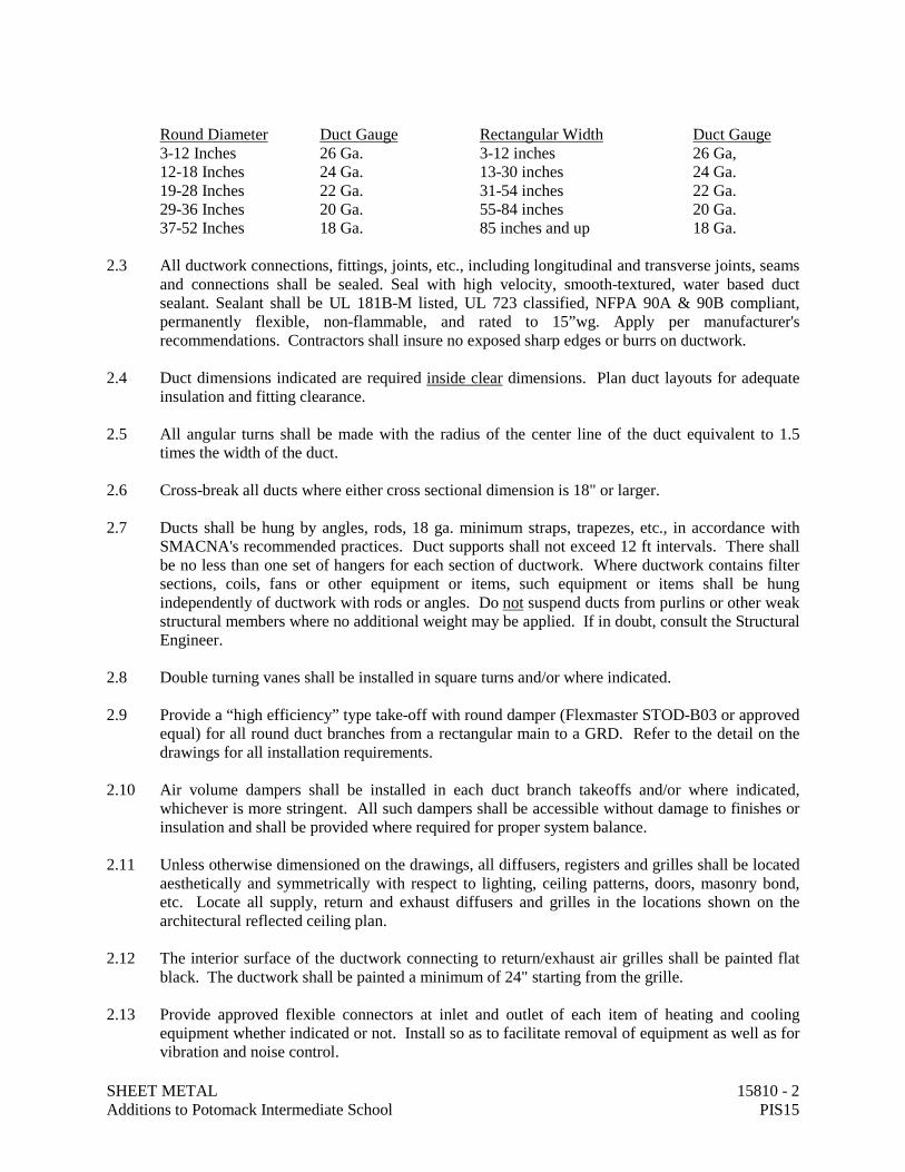
2.2 Ductwork, plenums and other appurtenances shall be constructed of the materials of the minimum
weights or gauges as required by the latest SMACNA 2” W.G. Standard or below table. When gauge thickness differs, the heavier gauge shall be selected. The below table shall serve as a minimum.
SHEET METAL 15810 - 2 Additions to Potomack Intermediate School PIS15
Round Diameter Duct Gauge Rectangular Width Duct Gauge
3-12 Inches 26 Ga. 3-12 inches 26 Ga, 12-18 Inches 24 Ga. 13-30 inches 24 Ga. 19-28 Inches 22 Ga. 31-54 inches 22 Ga. 29-36 Inches 20 Ga. 55-84 inches 20 Ga. 37-52 Inches 18 Ga. 85 inches and up 18 Ga.
2.3 All ductwork connections, fittings, joints, etc., including longitudinal and transverse joints, seams
and connections shall be sealed. Seal with high velocity, smooth-textured, water based duct sealant. Sealant shall be UL 181B-M listed, UL 723 classified, NFPA 90A & 90B compliant, permanently flexible, non-flammable, and rated to 15”wg. Apply per manufacturer's recommendations. Contractors shall insure no exposed sharp edges or burrs on ductwork.
2.4 Duct dimensions indicated are required inside clear dimensions. Plan duct layouts for adequate
insulation and fitting clearance. 2.5 All angular turns shall be made with the radius of the center line of the duct equivalent to 1.5
times the width of the duct. 2.6 Cross-break all ducts where either cross sectional dimension is 18" or larger. 2.7 Ducts shall be hung by angles, rods, 18 ga. minimum straps, trapezes, etc., in accordance with
SMACNA's recommended practices. Duct supports shall not exceed 12 ft intervals. There shall be no less than one set of hangers for each section of ductwork. Where ductwork contains filter sections, coils, fans or other equipment or items, such equipment or items shall be hung independently of ductwork with rods or angles. Do not suspend ducts from purlins or other weak structural members where no additional weight may be applied. If in doubt, consult the Structural Engineer.
2.8 Double turning vanes shall be installed in square turns and/or where indicated. 2.9 Provide a “high efficiency” type take-off with round damper (Flexmaster STOD-B03 or approved
equal) for all round duct branches from a rectangular main to a GRD. Refer to the detail on the drawings for all installation requirements.
2.10 Air volume dampers shall be installed in each duct branch takeoffs and/or where indicated,
whichever is more stringent. All such dampers shall be accessible without damage to finishes or insulation and shall be provided where required for proper system balance.
2.11 Unless otherwise dimensioned on the drawings, all diffusers, registers and grilles shall be located
aesthetically and symmetrically with respect to lighting, ceiling patterns, doors, masonry bond, etc. Locate all supply, return and exhaust diffusers and grilles in the locations shown on the architectural reflected ceiling plan.
2.12 The interior surface of the ductwork connecting to return/exhaust air grilles shall be painted flat
black. The ductwork shall be painted a minimum of 24" starting from the grille. 2.13 Provide approved flexible connectors at inlet and outlet of each item of heating and cooling
equipment whether indicated or not. Install so as to facilitate removal of equipment as well as for vibration and noise control.
SHEET METAL 15810 - 3 Additions to Potomack Intermediate School PIS15
2.14 All fans and other vibrating equipment shall be suspended by independent vibration isolators. 2.15 Miscellaneous accessories such as test openings with covers, latches, hardware, locking devices,
etc., shall be installed as recommended by SMACNA and/or as indicated. Test openings shall be placed at the inlet and discharge of all centrifugal fans, VAV boxes, fan sections of air handling units, at the end and middle of all main trunk ducts and where indicated. All such openings shall be readily accessible without damage to finishes.
2.16 Whether indicated or not, provide code approved, full sized fire dampers at all locations where
ductwork penetrates fire rated walls. Fire stop rating shall meet or exceed the rating of the wall. Provide an approved access panel at each fire damper located and sized so as to allow hand reset of each fire dampers. All such fire dampers and access panels shall be readily accessible without damage to finishes. Refer to Architectural Plans for locations of fire rated walls. All access doors shall be 16"x16" or as high as ductwork permits and 16" in length.
2.17 The Contractor who installs the sheet metal shall furnish to the Air Balancing Contractor, a
qualified person to assist in testing and balancing the system. 2.18 INSULATED FLEXIBLE AIR DUCT: Thermaflex G-KM or equal. Flexible air duct shall be
two (2) inch thick fiberglass insulation with CPE liner permanently bonded to a coated spring steel wire helix supporting a fiberglass scrim and fiberglass insulating blanket. Flexible air duct shall be listed under UL Standard 181 as a Class I flexible air duct complying with NFPA 90A and 90B. Maximum flame spread = 25 and maximum smoke developed = 50. Minimum insulating value is R-6.0. Flexible duct shall be used only for GRD runouts and no section shall be more than five feet in length.
2.19 FLEXIBLE CONNECTORS: Duro-Dyne, Ventfabrics, Inc., U.S. Rubber or equivalent;
conforming to NFPA No. 90A; neoprene coated glass fabric; 20 oz. for low velocity ducts secured with snap lock.
2.20 TURNING VANES: Fabricated as recommended by SMACNA: noiseless when in place without
mounting projections in ducts. All turning vanes shall be double blade type. 2.21 ACCESS DOORS IN DUCTWORK: Flexmaster TBSM, Air Balance, Vent Products or equal.
Access doors for rectangular ducts shall be 16"x16" where possible. Otherwise install as large an access door as height permits by 16" in length. Door shall be 2” thick double-wall insulated with continuous hinge and cam lock. Provide in ducts where indicated or where required for servicing equipment whether indicated or not. Provide a hinged access door in duct adjacent to all fire, smoke and control dampers for the purpose of determining position. Access doors shall also be provided on each side of duct coils and downstream side of VAV boxes and CAV boxes.
2.22 ARCHITECTURAL ACCESS DOORS IN CEILINGS OR WALLS: Provide Kees D Panel,
Cesco, Milcor or equal. Panels shall be 24”x24” in size and constructed with 16 gauge galvannealed steel for door and frame. Provide with primer finish to accept specified finish. Door shall include three (3) screwdriver operated cam latches and concealed continuous pivoting rod hinge. Door shall open 175 degrees. For masonry construction, furnish frames with adjustable metal masonry anchors. For fire rated units, provide manufacturer’s standard insulated flush panel/doors with continuous piano hinge and self-closing mechanism. The Contractor shall include all required access doors in the bid and shall coordinate with the General Contractor prior to the bid to insure a complete project.
SHEET METAL 15810 - 4 Additions to Potomack Intermediate School PIS15
2.23 VOLUME DAMPERS (RECTANGULAR): Ruskin MD35 or Air Balance, Pottorff, rectangular
volume dampers. Frames shall be 16 gauge galvanized steel. Blades shall be opposed blade 16 gauge galvanized steel with triple crimped blades on 6” centers. Linkage shall be concealed in jamb. Bearings shall be ½” nylon. Maximum single section size shall be 48" wide and 72" high. Provide with Ventfabrics 2" high elevated dial regulator to avoid damper handle from conflicting with duct insulation. Provide permanent mark on dial regulator to mark air balance point.
2.24 VOLUME DAMPERS (ROUND): Ruskin MDRS25 or Air Balance, Pottorff round volume
dampers. Dampers shall be butterfly type consisting of circular blade mounted to axle. Frames shall be 20 gauge steel and 6" long. Damper blades shall be 20 gauge crimped galvanized steel. Axle shall be 3/8"x6” square plated steel. Bearing shall be 3/8” nylon. Provide with Ventfabrics 2" high elevated dial regulator to avoid damper handle from conflicting with duct insulation. Provide permanent mark on dial regulator to mark air balance point.
END OF SECTION.
REGISTERS, GRILLES, DIFFUSERS & LOUVERS 15850 - 1 Additions to Potomack Intermediate School PIS15
DIVISION 15 – MECHANICAL SECTION 15850 – REGISTERS, GRILLES, DIFFUSERS & LOUVERS PART 1 – GENERAL: 1.1 The Contractor's attention is directed to the General and Special Conditions, GENERAL
PROVISIONS - MECHANICAL and to all other Contract Documents as they apply to this branch of the work. Attention is also directed to all other sections of the Contract Documents which affect the work of this section and which are hereby made a part of the work specified in this section.
PART 2 – REGISTERS, GRILLES AND DIFFUSERS: 2.1 Acceptable R, G & D manufacturers are Krueger, Anemostat, Nailor Industries, Titus and Tuttle
& Bailey. Shop drawings shall identify and list all characteristics of each device exactly as scheduled herein. Finishes for specified devices shall be selected by the Architect. Factory color samples shall be submitted with shop drawings. Devices shall be white unless noted otherwise. Aluminized steel devices are not acceptable. Steel devices are not acceptable unless specifically noted otherwise.
2.2 Include with the shop drawings a room-by-room schedule indicating devices installed. Also note
ceiling types and installations. 2.3 Refer to drawings for schedule. PART 3 – LOUVERS: 3.1 Acceptable louver manufacturers are Ruskin, United Enertech, Arrow. Shop drawings shall
identify and list all characteristics of each device exactly as scheduled herein. Finishes shall be selected by the Architect. Factory color samples shall be submitted with shop drawings.
3.2 Refer to drawings for schedule. END OF SECTION.

REGISTERS, GRILLES, DIFFUSERS & LOUVERS 15850 - 2 Additions to Potomack Intermediate School PIS15
This page has been left blank intentionally.
CONTROLS 15900 - 1 Additions to Potomack Intermediate School PIS15
DIVISION 15 - MECHANICAL SECTION 15900 - CONTROL - DIRECT DIGITAL (WEB BASED) PART 1 – GENERAL: 1.1 The controls system for this project shall be a web-based digital controls system. All controllers, control
interface hardware, services, installation, warranty, training, etc., shall be included as hereinafter specified. The system shall utilize a network controller and unitary" type controllers. Including such minor details not specifically mentioned or shown, as may be necessary for the complete operation of the system.
1.2 The Temperature Control Contractor (TCC) shall furnish all labor, materials, equipment, and service necessary for a complete and operating Building Automation System (BAS), utilizing Web Based Direct Digital Controls. All labor, materials, tools, equipment, software, software licenses, software configurations and database entries, interfaces, wiring, tubing, installation, labeling, engineering, calibration, documentation, samples, submittals, testing, commissioning, training services, permits and licenses, transportation, shipping, handling, administration, supervision, management, insurance, temporary protection, cleaning, cutting and patching, warranties, services, and items, even though these may not be specifically mentioned shall be included for the complete, fully functional and commissioned temperature controls system.
1.3 The TCC shall provide all items, articles, materials, devices, operations or methods listed, mentioned or
scheduled on the drawings including all labor, materials, equipment and incidentals necessary and required for their completion to provide a complete and operating temperature control system. This will include connecting to any mechanical equipment furnished with a control interface device and contacting the equipment suppliers and/or manufacturers for information for the proper interface to the equipment being furnished.
1.4 These apparatus' shall consist of, but not limited to, all necessary thermostats, sensing devices, automatic
dampers, damper motors, actuators, (except automatic dampers, valves, and damper motors furnished with HVAC equipment), and with the necessary accessories for the complete control of all equipment hereinafter specified.
1.5 Control sequences are specified at the end of this section. Provide all control equipment required to
perform sequences described. Coordinate all dampers with the sheet metal contractor and equipment provider. It is the responsibility of the control contractor to ensure all required dampers in the sequence of operations are provided.
1.6 Include all power wiring and cabling for the operation of the controls system. Refer to Electrical Division
Specifications for additional requirements. 1.7 APPROVED MANUFACTURER’S: Control System, Inc (Schneider Electric), Johnson Controls, Trane.
These TCCs/manufacturers have prior approval with the Owner and Engineer and are the only allowed suppliers and/or installing TCCs.
1.8 The TCC shall have an established working relationship with the control manufacturer of not less than five
years and shall have prior approval from the Owner and Engineer and are the only allowed suppliers and/or installing contractors. The TCC shall have a local office within 100 miles of the project site and provide service and/or replacement parts within a 24 hour notification of a control failure.
1.9 All bidders must be authorized distributors or branch offices of the manufactures specified. 1.10 A mandatory pre-installation meeting shall occur prior to the TCC beginning any work on site. This
meeting shall be attended minimally the prime contractor, mechanical contractor superintendent, TCC superintendent, Engineer, Owner and Architect. The purpose of the meeting is to have the controls installer communicate their understanding of the system design and how the system is intended operate to the

CONTROLS 15900 - 2 Additions to Potomack Intermediate School PIS15
Engineer and get the Engineer’s input and agreement. The agreement between the TCC and the mechanical engineer is to be thoroughly documented by the TCC for later reference.
1.11 The installation shall comply with the Local Authorities and State Fire Marshal code requirements,
including normal operating and smoke mode functions (where applicable). The installation shall comply with the requirements of the NEC, NFPA, UL and the Building Codes, including referenced mechanical, electrical, energy codes, etc.
1.12 ABBREVIATIONS:
• TCC – Temperature Control Contractor 1.13 The TCC shall list the following cost breakdowns, material and labor, on the official project schedule of
values: • Controls shop drawings • Controls graphics • Controls materials and labor • Controls startup, commissioning, testing, documentation (2.5% of controls contract value) • Controls training and Owner acceptance (2.5% of controls contract value)
PART 2 – GENERAL SYSTEM REQUIREMENTS:
2.1 The system shall provide a graphical, web-based operator interface that allows for instant access to any
system through a standard browser. All points of user interface shall be on standard PCs that do not require the purchase of any special software from the control’s manufacturer for use as a building operations terminal. The primary point of interface on these PCs will be a standard Web Browser. Network and controllers shall be of modular design providing distributed processing capability, and allowing future expansion of both input/output points and processing/control functions.
2.2 The intent of this specification is to provide a peer-to-peer networked, stand-alone, distributed control
system utilizing ANSI/ASHRAE Standard 135-2001 BACNet open and non-proprietary communication protocols in one open, interoperable system. All points shall be open and accessible for control and monitoring into a future county-wide school system networked EMS.
2.3 The operating system shall be based on a distributed control system in accordance with specifications. All
building controllers, application controllers and all input/output devices shall communicate via BACnet MS/TP communication protocol. Network controller shall communicate via BACnet over Ethernet (IP).
2.3.1 The Local Area Network (LAN) shall be either a 10 or 100 Mpbs Ethernet network supporting BACnet,
Modbus, Java, XML, and HTTP for maximum flexibility for integration of building data with enterprise information systems and providing support for multiple Network Server Controllers (NSCs), user workstations and a local host computer system.
2.4 The TCC contractor shall provide access to the system from a location determined by the Owner. 2.5 The TCC shall be responsible for coordination with the Owner’s IT staff to ensure that their system will
perform in the Owner’s environment without disruption to any of the other activities taking place on that WAN/LAN.
2.6 The TCC shall connect to any mechanical equipment furnished with a control interface device. The TCC
shall contact the equipment suppliers and/or manufacturers for information for the proper interface to the equipment being furnished. All points not provided with the equipment control interface are the responsibility of the TCC.
PART 3 – SUBMITTALS:
CONTROLS 15900 - 3 Additions to Potomack Intermediate School PIS15
3.1 The TCC shall not start the project installation until the shop drawing submittals have been reviewed by the Engineer.
3.2 Submittals shall include hardware, end devices, ancillary control components, a written operating sequence,
unitary control wiring, building floor plans showing communication cabling and labels as well as logic flow diagrams. All submittals shall be provided on paper and electronically in PDF format.
3.3 Submittals shall contain one control drawing per specified system and equipment. Drawing shall include
point descriptors (DI, DO, AI, AO), addressing, and point names. Each point names shall be unique (within a system and between systems). For example, the point named for the mixed air temperature for VHP #1, VHP #2, and VHP #3 shall not be MAT but should be named VHP#1MAT, VHP#2MAT, and VHP#3MAT. The point names should be logical and consistent between systems and VHP’s. The abbreviation or short hand notation (e.g., MAT) shall be clearly defined in writing by the TCC.
3.4 Control diagrams shall identify: System being controlled (attach abbreviated control logic text, all digital
points, analog points, virtual points, all functions (logic, math, and control) within control loop, legend for graphical icons or symbols, definition of variables or point names and detailed electric connections to all control devices and sensors.
3.5 Points list shall include all physical input/output. Points list shall be provided in both hard copy and in
electronic format and shall include: Name, address, engineering units, high and low alarm values and alarm differentials for return to normal condition, default value to be used when the normal controlling value is not reporting, message and alarm reporting as specified, identification of all adjustable points and description of all points.
3.6 Submittals shall contain floor plans depicting DDC control devices (control units, network devices, LAN
interface devices, and power transformers as well as static pressure sensor in duct and temperature sensors in rooms) in relation to mechanical rooms, HVAC equipment, and building footprint.
3.7 Submittals shall contain DDC system architecture diagram indicating schematic location of all control
units, workstations, LAN Interface devices, gateways, etc. Indicate address and type for each control unit, Indicate protocol, baud rate, and type of LAN per control unit.
3.8 Electrical wiring diagrams shall include motor start, control, and safety circuits and detailed digital
interface panel control point termination diagrams with all wire numbers and terminal block numbers identified. Indicate all required electrical wiring. Provide panel termination drawings on separate drawings. Clearly differentiate between portions of wiring that are existing, factory-installed and portions to be field-installed.
3.9 Show all electric connections of the controls system to equipment furnished by others complete to terminal
points identified with manufacturer’s terminal recommendations. 3.10 TCC shall provide one complete drawing that shows the control-wiring interface with equipment provided
by others. 3.11 Submittals shall include project specific graphic screens for each system including a picture of the screen
with a list of the variables to be placed on the screen. 3.12 Submittals shall include TCC’s hardware checkout sheets and test reports. 3.13 Submittals shall include the agenda for approval by the engineer and owner of the specified training
periods. See training section for requirements. 3.14 Provide complete panel drawings that are:
• Clearly labeled and schematic or drawn to scale. • Show the internal and external component arrangement so that the operators can identify the
CONTROLS 15900 - 4 Additions to Potomack Intermediate School PIS15
components by their position if the labels come off. • Wiring access routes shall also be identified so that Class 1 wiring is separated from Class 2 and 3 and
so high voltage wiring is segregated from low voltage wiring. • Complete identification of all control devices (manufacturer’s type, number, and function). • Provide details for labeling all wiring, control devices, and controllers. • Material and equipment descriptive material such as catalog cuts, diagrams, performance curves, and
other data to demonstrate conformance with specifications shall be provided. 3.15 Include room schedule including a separate line for each ERV and heat pump indicating location and
address. 3.16 Include control damper schedule including a separate line for each damper provided under this section and
a column for each of the damper attributes, including: code number, fail position, damper type, damper operator, duct size, damper size, mounting, and actuator type.
PART 4 – O&M MANUALS AND CLOSEOUT DOCUMENTS: 4.1 Refer to Mechanical Specification Section – REQUIRED SHOP DRAWINGS, ETC. for additional
requirements. 4.2 Operating instructions, maintenance procedures, parts and repair manuals shall be supplied. Repair
manuals shall include detailed instructions in the setup, calibration, repair and maintenance of all equipment furnished. Also supplied with these manuals will be a complete parts listing of all devices supplied which is to include part numbers and model numbers of all parts and component parts along with exploded views of devices.
4.3 All as built drawings (wiring diagrams, flowcharts, floor plans, etc.) shall also be supplied to the owner
electronically in PDF format. 4.4 System specific wiring, control diagrams, sequence of operation and points lists shall be as installed in each
control panel. This means as-built drawings, not design (submittal) drawings. 4.5 Supply all software necessary for configuration of, modification, editing or communicating to any of the
unitary devices. Software shall be capable of uploading and down-loading the entire unitary data base or any part of the automated system for backup or archiving.
4.6 Supply one copy of the software programming manual (hard copy and PDF format). The manual shall
describe all furnished software. The manual shall be oriented to programmers and shall describe calling requirements, data exchange requirements, data file requirements, and other information necessary to enable proper integration, loading, testing, and program execution.
4.7 Provide licensed electronic copies of all software. This includes, but is not limited to: project graphic images (editing/modifying/creating), project database, trouble-shooting and debugging programs, project-specific programming code and all other software required to operate and modify the programming code (including software at system level, primary control units, secondary control units, and all communication software). Any hardware devices (cables, protection devices) required to operate the software/hardware shall also be provided.
4.8 Provide a Bill of Materials with each schematic drawing. List all devices/equipment and match to
schematic and actual field labeling. Provide quantity, manufacturer, actual product ordering number, description, size, accuracy, operating ranges (voltage, temperature, pressure, etc.), input/output parameters, etc.
4.9 Maintenance manual shall include copies of signed-off acceptance test forms, commissioning reports, start-
up reports, etc.
CONTROLS 15900 - 5 Additions to Potomack Intermediate School PIS15
4.10 The TCC shall turn over to owner two (2) sets of computerized back-ups of the complete temperature control system.
PART 5 – WARRANTY & SOFTWARE LICENSES: 5.1 Labor and materials for the control system specified shall be warranted free from defects for a period of 12
months after substantial completion and acceptance. Control system failures during the warranty period shall be adjusted, repaired, or replaced at no additional cost or reduction in service to the Owner.
5.2 The TCC shall respond to the Owner's request for warranty service within 24 hours during normal business
hours. The TCC shall respond to the Owner's request for Emergency service (defined as life-threatening or creating the potential to cause property damage) during the warranty period within 4 hours.
5.3 The TCC shall provide technical phone support to the owner during the warranty period for warranty
related issues and for two years after the warranty period. If the technical support location of the TCC is outside of the toll free calling area for the customer, the TCC shall have a toll free number or accept collect calls for the purpose of providing technical support.
5.4 During the warranty period, standard parts for the DDC system shall arrive at the facility within 48 hours of
placing an order. Non-standard parts (requiring re-manufacturing or ordering from another supplier) shall be shipped within 96 hours.
5.5 Project-specific software, graphic software, database software, and firmware updates which resolve known
software deficiencies as identified by the TCC shall be provided and correctly installed at no charge during the warranty period.
5.6 Provide licensed electronic copies of all software for each workstation, laptop, server. This includes, but is
not limited to: project graphic images (editing/modifying/creating), project database, trouble-shooting and debugging programs, project-specific programming code and all other software required to operate and modify the programming code (including software at system level, primary control units, secondary control units, and all communication software). Any hardware devices (cables, protection devices) required to operate the software/hardware shall also be provided.
5.7 All additional licensing needed for this project shall be supplied by TCC. Software license shall not expire
or utilize any sort of protection hardware device for its use. In any case owner shall be free to direct the modification of any software license, regardless of supplier to allow open access to all controllers. Owner shall hold the software and firmware licensing. Software license shall not expire or utilize any sort of protection hardware device for its use.
5.8 System software shall be the latest version available with upgrades provided at the end of the warranty
period, and shall be fully licensed to the Owner for the entire system. Supply all software necessary for configuration of, modification, editing or communicating to any of the unitary devices. Software shall be capable of uploading and down-loading the entire unitary data base or any part of the automated system for backup or archiving. Software shall be "IBM compatible".
PART 6 – TRAINING: 6.1 A formal on-site "Hands On" training session shall be conducted for the owner's maintenance personnel.
This session shall be a minimum of one (1) eight (8) hour days to train the staff on setup, operation, and maintenance of all system(s) and/or devices. This will be at a time and location selected by the owner. One (1) additional eight (8) hour session shall be provided as “opposite season” training – generally 6 months into the warranty period. One (1) additional eight (8) hour session shall be provided at a later date. (This may be requested any time during the warranty period.) All training materials and books shall be provided. Both sessions shall be given by the manufacturers "factory" technical representative. (This is defined as someone other than the installing contractor’s representative.) All expenses are to be provided by the TCC. All training sessions shall be scheduled at owner’s request.
CONTROLS 15900 - 6 Additions to Potomack Intermediate School PIS15
6.2 TCC shall conduct training courses for designated personnel in operation and maintenance of system.
Training shall be oriented to specific system being installed under his contract and shall be digitally recorded and submitted on DVD by the TCC.
6.3 Training shall be a mix of, test exercises, and actual keyboard entry and screen viewing at the operator’s
terminal. A curriculum shall be discussed and implemented based on the level of expertise of the employees. Hands-on experience and problem solving shall be emphasized.
6.4 If during any training session, the trainer/owner finds more than three (3) items that need repair, the
training session will be immediately terminated. The session will be rescheduled for another date. The re-scheduled training session will be carried out at no additional cost to the Owner.
6.5 The training shall be oriented to making the owner self sufficient in the day-to-day use and operation of the
DDC system. 6.6 Additionally, the training shall include:
• System start-up, shutdowns, power outage and restart routines, alarms, security levels, changing setpoints, changing schedules and other parameters, overrides, freeze protection, manual operation, return to automatic operation, and resetting equipment.
• All screens shall be discussed, allowing time for questions. • Information specifically focused on showing the owner methods of troubleshooting the mechanical
systems using the DDC. • Use of laptop and hand-held operator interface device, if applicable. • Creating, modifying, viewing, downloading, and reloading, trend logs. • Remote access to the system. • The other training sessions shall be oriented toward answering specific questions from Owner’s staff. • The trainer must be well grounded in both DDC system operation and in mechanical systems service
and shall be the programmer. 6.7 This documentation and process shall be complete, approved and accepted by Engineer and Owner prior to
acceptance. This information shall be documented as completed. A copy shall be delivered to the Engineer and Owner and included in the O&M manuals.
PART 7 – COMMISSIONING & VERIFICATION, FUNCTIONAL PERFORMANCE TESTING & CHECKLISTS: 7.1 100% compliance with the requirements of this section is a condition of the Owner’s acceptance and start
of the warranty period. 7.2 The TCC shall be responsible for completion of (1) their hardware checkout sheets and test reports, (2)
Point-by-point confirmations of ALL points – this includes visual inspection of installed components, and (3) sequence of operation confirmation.
7.3 This documentation and process shall be complete, approved and accepted by Engineer and Owner prior to
acceptance. This information shall be documented as completed. A copy shall be delivered to the Engineer and Owner and included in the O&M manuals. Each subcontractor shall be responsible for completion of their own System Verification Checklists/Manufacturer’s Checklists. Sample checklists shall be submitted to the Engineer and Testing Agent for approval.
7.4 Air and water balancing shall be completed (and discrepancies resolved) before the TCC’s final system
check and before the acceptance test to be conducted in the presence of the Engineer. 7.5 Refer to Mechanical Specification Section – GENERAL PROVISIONS for additional information and
requirements.
CONTROLS 15900 - 7 Additions to Potomack Intermediate School PIS15
PART 8 – WIRE MANAGEMENT, ELECTRICAL POWER, ETC: 8.1 Refer to CABLING section of this specification for additional requirements. 8.2 Electrical work required for system interlock and installation of the temperature control system shall be
included in the bid and installed per all applicable codes. Coordinate with other trades as required for installation of a complete system.
8.3 All wiring and cabling in mechanical and electrical rooms shall be in conduit. No wiring or conduit can be
exposed to view in any other area. Conceal all wiring and cabling in conduit in wall from thermostats or other controls devices to above ceiling. Install conduit in wall from wall thermostats to above ceiling for cabling. Route wiring directly to cable tray from control points above the ceiling. Rough-in for control devices shall be in compliance with the requirements of the ELECTRICAL SPECIFICATIONS.
8.4 Any power for controls shall be fed from dedicated circuits in emergency electrical panels, when provided
for a project, and shall not be obtained from receptacles, lighting, or equipment circuits. Unitary control power may be obtained from the equipment served. If power is obtained from the equipment served, the power may not be interrupted to the electronics if the equipment is off for any reason.
8.5 The TCC shall be responsible for the power source to any control panels, unitary controllers, etc. on any
controlled equipment and all other control power requirements. This includes circuit breakers, wiring, conduit, etc. installed in strict accordance with NEC. The TCC may contract with the electrical contractor for the power wiring installation.
8.6 Prior to installation, insure through coordination with all trades, that appropriate clearances (36” minimum)
as required by the N.E.C. are maintained at all control panels, including unitary controllers for VAV terminals, heat pumps, etc.
8.7 The TCC shall provide all CAT5 or CAT6 cabling network cabling for a complete system. This shall
include cabling to the Owner’s data drop. The main system data drop will be provided by others. 8.8 All control circuits within the electrical panels shall be marked to indicate equipment served. 8.9 The TCC shall perform all temperature control interlock wiring. This shall include control valves,
dampers, thermostats, indoor/outdoor HVAC systems, etc. Electrical work required for system interlock and installation of the temperature control system shall be included in the bid and installed per all applicable codes. Coordinate with other trades as required for installation of a complete system.
8.10 The TCC shall be responsible for any power required for the unitary controls or control panels. This
includes circuit breakers, wiring, conduit, etc. installed in strict accordance with NEC. The TCC may contract with the electrical contractor for the power wiring installation.
8.11 Provide one outlet mounted inside the control panel and separately fused with a non-time delay fuse at 15
A at any panel location containing electronic control components. This receptacle may be served from the control panel 120 VAC power source.
8.12 All wiring shall be continuous runs. Any junctions must be made in metal enclosure. 8.13 Grounding terminals shall be color coded green and yellow and shall be compatible with the other specialty
terminals specified above and shall mount on the same DIN rail system. Units shall be arranged so that the wiring connected to them is grounded to the enclosure via the mounting rail. These terminals shall be provided for grounding cable shields at the points where the cables enter a control panel and terminate on the control panel terminal strip. Terminals shall be Entrelec M 4/5.3A.PI or equivalent by Weidmuller, Phoenix, or Allen Bradley.
CONTROLS 15900 - 8 Additions to Potomack Intermediate School PIS15
8.14 All new lighting control panels, new Building Automation Systems control panels, and new conventional HVAC control panels be certified as being constructed and wired in accordance with NFPA 70 110.3 (a) (1) and article 409.
8.15 Contractor shall insure control panels have an identification label stating the “Certification Agency” such
as UL, CSA, CE, etc. or a label of certification for each control panel by a Professional Engineer (P.E.) registered in the State of West Virginia, stating that the design of the control panel was under their direct supervisory control. Include with shop drawings.
8.16 An electrical contractor licensed by the State of West Virginia with a licensed Master Electrician and a
licensed on-site electrician can install the electrical wiring for lighting controls systems or Building Automation Systems (BAS).
PART 9 – CABLING: 9.1 Refer to WIRE MANAGEMENT section of this specification for additional requirements. 9.2 ALL CONTROL WIRING SHALL BE INSTALLED IN A WIRE MANAGEMENT SYSTEM TO
INCLUDE CABLE TRAYS, BRIDLE RINGS, & CONDUITS. NO EXCEPTIONS! COORDINATE WITH ELECTRICAL CONTRACTOR TO INSURE A COMPLETE WIRE MANGEMENT SYSTEM.
9.3 Acceptable cable manufacturers are Belden, West Penn or Alpha. 9.4 A complete cabling system shall be furnished and installed, which shall adhere to the highest workmanlike
standard of quality and appearance. Cabling shall be installed square with building lines and contained within a wire management system.
9.5 All sizing of cabling shall be according to manufacturer’s recommendations, but shall be a minimum of 18
AWG. Communication cable shall be 22 gauge. 9.6 Furnish a floor plan of the building indicating communication cable labeling and routing as well as
addresses and branch wiring from the unitary devices. All cabling shall be labeled on both ends. The type, size and label of all cabling shall be indicated on submittal floor plan drawings.
9.7 Wall space temperature sensor cabling (from the sensor to the unitary controller) shall have a minimum of
four (4) conductors. 9.8 All cabling shall be stranded. "NO" solid conductors will be accepted. All cabling shall be 100% shielded
with appropriate drain wire and insulation. 9.9 All cable connections shall be continuous run (including shield). Any junctions in communication trunk
must be made in a metal enclosure, connections must be soldered, taped and the metal enclosure must be mechanically attached to the nearest ground. Device wiring can be wire nuts. No crimped connections will be accepted. Note location of junction boxes on the as built floor plans. All cabling networking unitary controllers, and other networked equipment, shall be in soldered.
9.10 All shields must be terminated as per manufacturer’s recommendation. Shield termination requirements by
the manufacturer must be provided with submittals. 9.11 Wireless controllers are not approved unless specifically mentioned in the sequence of operations or noted
on plans. PART 10 – SYSTEM SOFTWARE: 10.1 System software will be the latest version available with upgrades provided for full warranty period, and
CONTROLS 15900 - 9 Additions to Potomack Intermediate School PIS15
shall be fully licensed to the owner for all network controllers and servers. Refer to WARRANTY section of this specification for additional requirements.
10.2 The BAS shall include trend logging screens accessible from tabs on the home page for building utilities
usage. 10.3 System software shall, at a minimum, provide:
• Monitor and supervise all control points. • Add new points and edit system database. • Change control setpoints, timing parameters and loop tuning of PID coefficients in all control loops in
all control units. • Enter programmed start/stop schedules. • View alarm and messages. • Modify existing control logic (or sequence of operation) in all control units. • Upload/Download programs, databases, control parameters, etc. • Modify graphic screens.
10.4 Sequence of operation programming methodology - The application software shall be user programmable.
Application programming shall be (1) Line type programming that uses text programming in a language similar to BASIC or FORTRAN, or (2) graphical block programming - The method of programming shall be by manipulation of graphic icon "blocks." Each block represents a subroutine containing the programming necessary to execute the function of the device that the block represents.
10.5 Unitary Control Unit Database Archiving - The host software shall provide capability to upload sequence
of operation, database, and other control parameters from each controller. Uploaded programs shall be retained on hard disk for system backup. Programs may be modified using Editor functions, and downloaded to individual controllers as desired. Downloading of databases shall not interrupt other multi-tasked functions that are ongoing.
PART 11 – NETWORK CONTROLLER 11.1 Network controllers with I/O modules are acceptable. 11.2 One network controller is required to act as server so that all building equipment can be accessed from 1 IP
address. Coordination of IP address with Owner shall be responsibility of TCC. 11.3 Install the Network Controller in a surface mounted panel, NEMA type 1 enclosures, with a removable
hinged door. Provide a flush mounted key lock. All control panels must be painted the same color and identified. The boxes are to be made from 16 gauge material. Panels should not be provided with knockouts.
11.4 Control panels shall be constructed by a UL approved panel manufacturer. The standard used shall be
UL508A. All proper labels are to be attached. Panel shall meet arc flash requirements. 11.5 The Network Controller shall be web-based and communicate BACnet IP. It shall issue all time schedules,
summer/winter commands, customized trending, holiday scheduling, alarm handling, clock or other shared commands to all unitary controllers within the building network. If for any reason communications between the unitary(s) and the Network Controller is lost, the unitary(s) shall operate in a stand-alone manner (in day operation) until communications is restored. It shall also operate in the “summer” or “winter” mode as last commanded.
11.6 The Network Controller shall be integrated and interoperable with the facility infrastructure and include
user access to all system data locally over the Local Area Network (LAN) / Wide Area Network (WAN) within the building and remotely by a standard Web Browser over the Internet. Any computer connected to the network, utilizing a web browser and having the proper password.
CONTROLS 15900 - 10 Additions to Potomack Intermediate School PIS15
11.7 The Network Controller shall be a fully user-programmable, supervisory controller. It shall monitor the
network of distributed unitary controllers, provide global strategy and direction, and communicate on a peer-to-peer basis with other Network Controllers.
11.8 The Network Controller shall have battery back-up to allow a minimum of seven days of operation. The
Network Controller shall be composed of one or more independent, stand-alone, microprocessor to manage the network strategies described in Application software section. The network controller shall have ample memory to support its operating system, database and programming requirements. The operating system of the Network Controller shall manage the input and output communications signals to allow distributed unitary controllers to share real and virtual point information and allow central monitoring and alarms. The database and custom programming routines of the Network Controller shall be editable from a single operator station.
11.9 The Network Controller shall be remotely monitored via the internet. Additionally, it shall include
automatic emailing and texting out alarms, gathering alarms, reports and logs, programming and downloading database.
11.10 The Network Controller shall continually check the status of all processor and memory circuits. If a failure
is detected, the controller shall: • Assume a predetermined failure mode. • Emit an alarm. • Display card failure identification.
11.11 Under no circumstance shall more than 75% of the total number of sensor and control points be connected
through a single Network Controller. Each DDC system component shall provide for the future addition of at least 20% of each type of the number of sensor and control points connected to that component including a minimum of one universal input and one universal output.
PART 12 – UNITARY CONTROLLER 12.1 Each piece of equipment shall have its own Unitary Controller (i.e., heat pump and ERV). The Unitary
Controller for each piece of equipment shall be mounted on the side of the unit. The Unitary Controller for all other equipment shall be mounted in a panel and properly labeled. Refer to drawings for mechanical equipment with factory mounted DDC controller.
12.2 Factory mounted controls from the OEM shall be provided with read and write capability for the BACnet IP points. Coordinate with equipment manufacturer’s representative. Refer to equipment specification for points required and sequences of operation.
12.3 Unitary Controllers used in conditioned ambient shall be mounted in dust-proof enclosures, and shall be
rated for operation at 32 degrees F to 120 degrees F. All Unitary Controllers shall have an RJ-11 or similar type connection for monitoring or programming access by room or local equipment level with access to any unitary within the network without modification.
12.4 Control panels shall be constructed by a UL approved panel manufacturer. The standard used shall be
UL508A. All proper labels are to be attached. Panel shall meet arc flash requirements. 12.5 Unitary Controllers utilized in the network shall have full stand alone capability including time of day and
holiday scheduling as well as all energy management functions such as optimal start/stop, duty cycling, etc. The terminal unit Unitary Controllers may be pre-programmed with the project specific sequence of operation as specified for the application. Any re-programming of the electronics shall be performed on location using a portable personal computer with appropriate software or through the Network Controller. The entire unitary data base shall have the capability of being backed up and or downloaded locally.
CONTROLS 15900 - 11 Additions to Potomack Intermediate School PIS15
12.6 All points to have a unique digital input to the BAS system. The use of digital point count expanders is not an acceptable replacement to digital inputs to the unitary controller. The conversion of a single universal input channel to accept up to multiple voltage free contacts such as relay contacts, auxiliary starter contacts, differential pressure switches, etc. IS NOT ACCEPTABLE.
12.7 Unitary Controllers shall communicate via BACnet MSTP communication protocol. A BACnet Protocol
Implementation Conformance Statement (PICS) shall be provided for each Unitary Contoller that will communicate on the BACnet MS/TP Bus.
12.8 All Unitary Controllers shall be fully application programmable. All control sequences within or
programmed into the unitary controller shall be stored in non-volatile memory, which is not dependent upon the presence of a battery shall be retained.
12.9 Unitary Controllers shall have a 10% spare point capacity to be provided for all applications. 12.10 After a power failure, the Unitary Controller shall operate the control application using the current setpoints
and configuration. Reverting to default or factory setpoints are not acceptable. PART 13 – SENSORS AND MISCELLANEOUS DEVICES: 13.1 WEATHER STATION HOUSING: Provide Kele Model A21 Outdoor Aspirated Humidity/Temperature
housing. NEMA 3R enclosure is painted white to reduce the effect of radiation, and the enclosure has a lockable latch for security. The outdoor air sensor will be installed on the north wall in the shade as not to be effected by sunlight, building ventilation or weather. This location shall be indicated on the control drawings. Installation in outside air ductwork or louvers is not acceptable. If not installed to provide "accurate" temperature readings, it shall be relocated (at the TCC’s expense) until a suitable location is found.
13.2 SENSOR RESOLUTION: All temperature sensors shall have a minimum resolution of 1/10th of 1 degree
F. (0.1 degree F.) Sensor stability shall be 0.24 degrees over a year period. Space sensors shall be tested and accurate to within 0.75 degrees F. Outside air, water and duct sensors shall be tested and accurate to within 2.0 degrees F.
13.3 SPACE SENSORS AND THERMOSTATS:
• Refer to the drawings for proper type and location. • All thermostat and sensors shall be provided with temperature indication, unless otherwise noted. • Programmed set-point shall be locally adjustable limited to 2 degrees above set-point and 2 degrees
below set-point for supervised areas. • Unsupervised areas shall have non-adjustable set-point. • Generally, thermostats/sensors shall be installed 5'-0" above the finished floor. • Where thermostats/sensors are to be mounted next to a light switch, install at the same height as the
light switch. • Sensors in hallways, vestibules, stairways, restrooms and locker rooms shall utilize a stainless steel
surface mount temperature sensor installed on an interior wall or partition (2"x4" blank plate). Care must be taken in the installation of these sensors to ensure proper insulation from the wall temperatures in order to properly sense space temperature.
• If there is a question consult engineer prior to rough-in. • Thermostats shall be capable of manual override during unoccupied hours.
13.4 DISCHARGE AIR SENSORS: Shall be rigid insertion type. In all applications, care shall be taken to
insure that the sensors are securely mounted as not to allow any vibration and installed in such a manner as to indicate the truest possible temperature.
13.5 RELAYS: Relays for starting and stopping fractional horsepower motors shall be rated as follows:
• 1/4 horsepower motors or less use 15 ampere rated relays,
CONTROLS 15900 - 12 Additions to Potomack Intermediate School PIS15
• 1/3 horsepower motors use 20 ampere rated relays, • 1/2 horsepower motors use 30 ampere rated relays, • Relays used for pilot duty service shall be rated at a minimum of 10 amperes. • Provide auxiliary pilot duty relays on motor starters as required for control function. • Do not install control and status relays in packaged equipment control panel enclosures containing
Class 1 starters. 13.6 CURRENT SENSING DEVICES: Veris Industries model Hx08 Series and H701 or equal. All current
sensors shall be capable of alarming to the BAS for belt losses, pump coupling shear or other mechanical failure on loads.
PART 14 - DAMPERS AND ACTUATORS: 14.1 Unless otherwise specified, valves shall be furnished and sized by the TCC. The valves are to provide the
required capacity and the close off rating shall be in excess of the system pressures encountered (minimum 40 psi differential). Proportioning-type valve bodies shall be packed type with throttling type inner valve (quick close plug shall not be acceptable). Proportional type valves to be rated at 125 psi static pressure. Modulating control valves shall be selected within a 3-5 psig pressure drop range. Two position control valves (open/close) shall be line size.
14.2 Dampers for various units requiring field mounting shall be tight closing, "ultra low leakage", opposed
blade with side and edge seals. They shall be sized and furnished under this section. Installation of dampers shall be by the sheet metal contractor, coordinated by the TCC. Frames shall be no less than 16 gauge galvanized steel and furnished with mounting holes for duct mounting. Damper blades shall be no less than 14 gauge galvanized steel with maximum blade width of 8 inches. Blades shall be secured to 1/2 inch zinc plated axles and hardware with nylon bearings. Provide thrust bearings at the end of each blade. All dampers shall have end switches to positively prove damper position. No Exceptions!
14.3 All damper actuators shall be fail safe spring return type with sufficient force to operate the dampers or
valves under all normal operating conditions. They shall return to the normally open position upon a loss of power.
14.4 "ALL" Actuators shall be of the same manufacturer and have internal feedback circuitry to provide a
positive action to insure proper positioning of the damper or valve through the entire sequence. Actuators shall have an adjustable starting point to accurately set the range of travel to the output of the controller. All actuators shall also utilize the same input signal (6-9 VDC, 0-010V, 2-10 VDC, 4-20 MA) in order to maintain some consistency in the control application. Analog actuation is 6-9 VDC, 0-010V, 2-10 VDC or 4-20 MA, floating point control with 2 digital outputs is NOT approved as analog actuation.
14.5 Actuators may be factory installed. If not factory installed they shall be installed as per instructions by the
terminal equipment manufacturer. 14.6 Locations mounted above ceiling shall be marked on ceiling grid. 14.7 Install damper motors on the outside of the duct in warm areas where possible, not in air stream or
locations exposed to outdoor conditions. PART 15 – GRAPHICS SCREENS AND TRENDS: 15.1 All graphics screens shall be submitted for review by Engineer. Provide the following animated, color
graphics screens minimally: 15.2 Entire floor plan home screen with OAT, Time and Date displays.
• Floor plan showing major zones,

CONTROLS 15900 - 13 Additions to Potomack Intermediate School PIS15
• Click major zone displays enlarged floor plan of the zone showing individual heat pump zones & numbers. Include link to respective mechanical room.
• Click individual zone shows heat pump graphic. Display all data points from points list, occ/unocc schedule and setpoints, OAT, Time and Date.
15.3 Color Graphic Screens shall be designed for all mechanical systems and shall include the following:
• A graphic shall be the starting page with the building graphically indicated. Break up the floor plan into zones to match Contract Documents. The building shall be the point of reference to enter into the respective building control system.
• All heat pump units including pumps. • All OA units. • All floor plans indicating all actual room numbers, thermostats and mechanical equipment. Operator
shall be capable of clicking on any equipment and pull up the respective graphic screen. 15.4 Graphics to include floor plans with room numbers (as-built room numbers) and thermostat locations, links
to flow diagrams for heat pumps and outside air systems. 15.5 All new graphics shall match the existing system graphics, unless noted otherwise. 15.6 The graphical programming software shall allow for interactive mouse-driven placement of block icons on
the graphic screen and connection of block inputs to block outputs by means of drawing lines to form a graphic logic diagram. The user shall not have to manually input text to assign block input/output interconnections. Blocks shall allow entry of adjustable settings and parameters via pop-up windows.
15.7 The clarity of sequence shall be such that the user has the ability to verify that the system programming
meets the specs without having to learn or interpret a manufacturer’s unique programming language. Provide a means for testing and/or debugging the control programs off-line (not communicating with control units) using operator entered values for physical inputs and time. Provide a means for testing and/or debugging the control programs on-line (communicating with control units), showing actual physical inputs land all block outputs in real time.
15.8 Provide a utility that shall allow the graphic logic diagrams to be directly compiled into application
programs. Logic diagrams shall be viewable either off-line, or on-line with real-time output values. 15.9 All graphic software shall be in the html web browser format and support multiple simultaneous screens to
be opened and resizable in a "Windows" type environment. All functions, except text entry, shall be executable with a mouse. Graphic software shall provide for multitasking such that third party programs can be used while the Operator Workstation Software is on-line. Provide the ability to alarm graphically even when operator is in another software package. The software shall allow for Owner to create user defined, color graphic displays of geographic maps, building plans, floor plans, and mechanical and electrical system schematics.
15.10 The contractor shall provide libraries of pre-engineered screens and symbols depicting standard air
handling unit components (e.g. fans, coils, filters, dampers, etc.), mechanical system components (e.g., pumps, heat pumps, etc.), complete mechanical systems (e.g. VAV, etc.) and electrical symbols.
15.11 The graphic development package shall use a mouse or similar pointing device to allow the user to perform
the following: • Define symbols • Position items on graphic screens • Attach physical or virtual points to a graphic • Define background screens • Define connecting lines and curves • Locate, orient and size descriptive text • Define and display colors for all elements
CONTROLS 15900 - 14 Additions to Potomack Intermediate School PIS15
• Establish correlation between symbols or text and associated system points or other displays. • Create hot spots or link triggers to other graphic displays or other functions in the software
15.12 The TCC shall including programming of 25 point trends as directed by the Engineer. These can be
requested at any time during the project including the warranty period. Trend “change of state” for digital inputs. Trend analog points in 30 minute increments. Maintain trend history for 30 days. Include the following: • Outside air temperature • OA unit leaving air temperatures for each unit • Geothermal wellfield main supply and return temperatures • Geothermal wellfield main flow rate • Others as directed in the field
PART 16 - TIME SCHEDULES (ALL TIMES SHALL BE USER ADJUSTABLE): 16.1 During construction, the time schedule (for all equipment except OA unit) will be Occupied at 5:00 AM,
Unoccupied at 10:30 PM. seven (7) days a week. 16.2 When the system is fully tested and operational and after the Owner’s staff have been fully instructed as to
the operation of the system the schedule shall be as follows unless otherwise instructed: 16.3 CLASSROOMS: Monday through Friday Occupied mode at 7:15 AM, Unoccupied mode at 3:30 PM.
Unoccupied for Saturday and Sunday. Stage Classrooms in Area B on first, Area C on 15 minutes later and all other spaces 15 minutes after Area C.
16.4 Building outside air handling unit shall operate Monday thru Friday, 7:50 AM to 2:40 PM. 16.5 Each piece of equipment shall have its own adjustable time schedule. 16.6 All schedules shall be coordinated and confirmed with the Owner prior to final implementation. PART 17 - GEOTHERMAL HEAT PUMPS WITH FACTORY DDC CONTROLLER: 17.1 Factory mounted controls from the OEM shall be provided with read and write capability for the BACnet
IP points. Coordinate with equipment manufacturer’s representative. Refer to HVAC Equipment specification Section 15700 for points required and sequences of operation.
PART 18 – ENERGY RECOVER VENTILATOR: 18.1 The system shall operate under the control of a local, stand-alone, microprocessor based DDC controller.
The DDC controller shall be provided by the TCC. 18.2 Each system shall be placed into the occupied/unoccupied mode based upon the user adjustable schedule.
The unit shall be off when scheduled as unoccupied and warm-up. 18.3 If communication is lost between the Network Control Panel and the Outside Air System Controller, then
the Outside Air System shall be placed into the unoccupied mode until communication is restored. 18.4 In the unoccupied mode the supply/exhaust fan and energy recovery wheel shall be OFF, the outside/
exhaust air damper shall be fully closed. 18.5 When placed into the occupied mode, the Mode of Operation shall be determined and then the following
shall occur in sequential order: • The outside air damper and exhaust air damper shall fully open and be proved via end switch. If the
dampers do not prove open an alarm shall be at the BAS and the fans shall not start.
CONTROLS 15900 - 15 Additions to Potomack Intermediate School PIS15
• The supply fan and exhaust fan shall be 750 cfm. Coordinate with TAB scope. 18.6 The ERV shall be constant volume when in occupied mode. PART 19 – POINTS LIST – SEE ATTACHED:
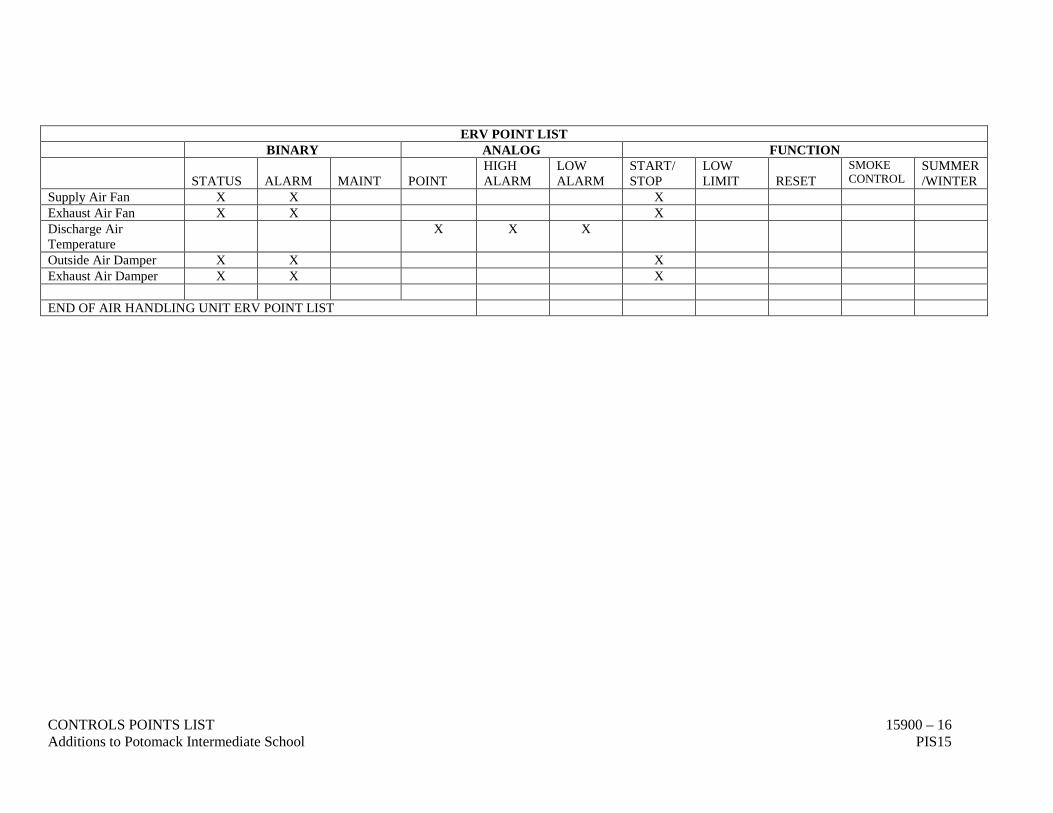
CONTROLS POINTS LIST 15900 – 16 Additions to Potomack Intermediate School PIS15
ERV POINT LIST BINARY ANALOG FUNCTION
STATUS ALARM
MAINT
POINT
HIGH ALARM
LOW ALARM
START/ STOP
LOW LIMIT
RESET
SMOKE CONTROL
SUMMER/WINTER
Supply Air Fan X X X Exhaust Air Fan X X X Discharge Air Temperature
X X X
Outside Air Damper X X X Exhaust Air Damper X X X END OF AIR HANDLING UNIT ERV POINT LIST
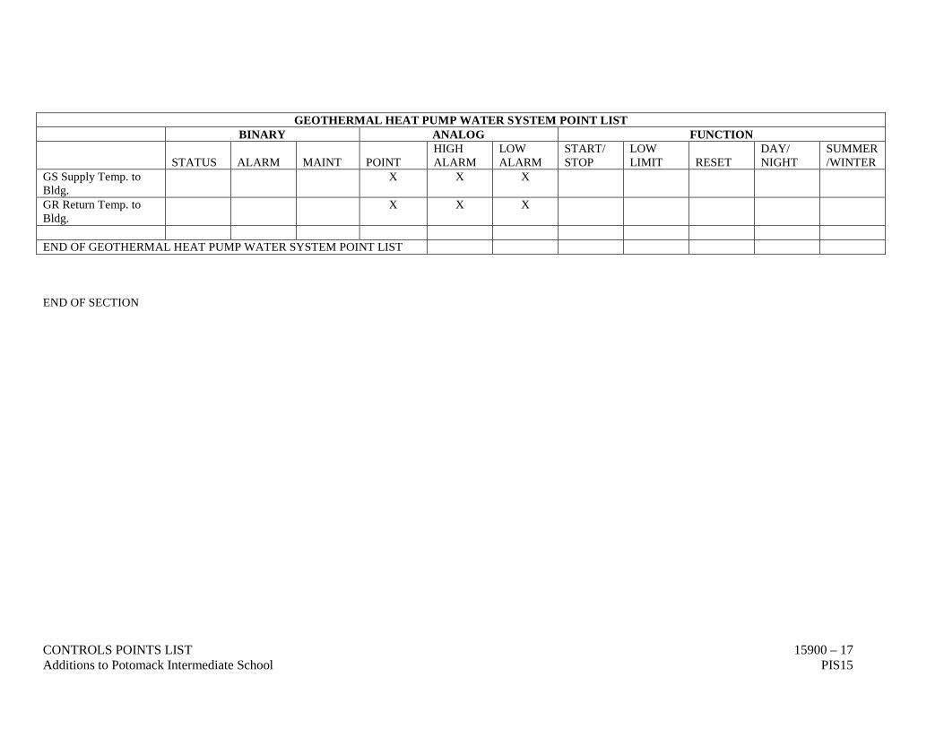
CONTROLS POINTS LIST 15900 – 17 Additions to Potomack Intermediate School PIS15
GEOTHERMAL HEAT PUMP WATER SYSTEM POINT LIST BINARY ANALOG FUNCTION
STATUS ALARM
MAINT
POINT
HIGH ALARM
LOW ALARM
START/ STOP
LOW LIMIT
RESET
DAY/ NIGHT
SUMMER/WINTER
GS Supply Temp. to Bldg.
X X X
GR Return Temp. to Bldg.
X X X
END OF GEOTHERMAL HEAT PUMP WATER SYSTEM POINT LIST END OF SECTION
CONTROLS POINTS LIST 15900 – 18 Additions to Potomack Intermediate School PIS15
This page has been left blank intentionally.
TESTING, BALANCING, LUBRICATION AND ADJUSTMENTS 15950 - 1 Additions to Potomack Intermediate School PIS15
DIVISION 15 - MECHANICAL SECTION 15950 - TESTING, BALANCING, LUBRICATION AND ADJUSTMENTS PART 1 – GENERAL: 1.1 The Contractor's attention is directed to the General and Special Conditions, GENERAL
PROVISIONS - MECHANICAL and to all other Contract Documents as they apply to this branch of the work. Attention is also directed to all other sections of the Contract Documents which affect the work of this section and which are hereby made a part of the work specified in this section.
1.2 The Engineer, or authorized representative, shall be notified by the Contractor twenty-four (24)
hours in advance of any tests called for in these Specifications or required by others. 1.3 Only after written approval, signed by the Engineer, shall the Contractor apply insulation or paint
or allow the work to be furred-in. This written approval, however, does not relieve the Contractor of the responsibilities for any failure during the guarantee period. The expense of all tests shall be borne by the Contractor, along with all temporary equipment, materials, gauges, etc. required for tests.
PART 2 - HEATING, VENTILATING AND AIR CONDITIONING TESTING: 2.1 The test and balance of this system shall be by a Contractor who employs only the services of a
certified AABC or independent NEBB firm whose sole business is to perform test and balance services.
2.2 The test and balance contractor shall bid directly to the Mechanical Contractor or Construction
Manager or Owner. 2.3 Mechanical Contractor shall provide all start-up documents to Test and Balance Contractor prior
to any test and balance services. 2.4 The Mechanical Contractor shall test all piping before being insulated or concealed in any
manner. Where leaks or defects develop, required corrections shall be made and tests repeated until systems are proven satisfactory. Water piping systems shall be subjected to a hydrostatic test as specified and shall be proven tight after a twenty-four (24) hour test.
2.5 All motors, bearings, etc. shall be checked and lubricated as required during start-up procedures.
All automatic, pressure regulating and control valves shall be adjusted. Excessive noise or vibration shall be eliminated.
2.6 System balancing, where required, shall be performed only by persons skilled in this work. The
system shall be balanced as often as necessary to obtain desired system operation and results. 2.7 All fan belts shall be adjusted for proper operation of fans. 2.8 Testing shall occur after completion of the ceiling systems installation. 2.9 All deficiencies observed by the Test and Balance Contractor shall be reported immediately to the
Engineer and Mechanical Contractor.

TESTING, BALANCING, LUBRICATION AND ADJUSTMENTS 15950 - 2 Additions to Potomack Intermediate School PIS15
2.10 Refer to Specification Section GEOTHERMAL LOOP SYSTEM and Specification Section
CONTROLS for additional requirements. 2.11 Refer to Specification Section – CONTROLS – DIRECT DIGITAL for additional requirements. 2.12 Refer to Specification Section – GENERAL PROVISIONS – MECHANICAL for startup
requirements. 2.13 Provide a preliminary test report to the Engineer immediately after the system is air balanced, or
any initial phases are balanced. This report may be hand written. Any systems that are not found to operate within the design tolerances by the Test and Balance Contractor shall be immediately be reported to the Engineer via telephone call to attempt to determine a resolution while the Test and Balance Contractor is still on site. Additional compensation will not be accepted for additional trips.
2.14 Anticipate visiting the site again after the Engineer has reviewed the report. The Engineer may
request up to two (2) additional site visits for onsite troubleshooting where additional measurements may be required.
2.15 For the purpose of placing the Heating, Ventilating and Air Conditioning systems in operation
according to design conditions and certifying same, final testing and balancing shall be performed in complete accordance with AABC Standards for Total System Balance, Volume Six (2002), for air and hydronic systems as published by the Associated Air Balance Council.
2.16 THE FOLLOWING SYSTEMS SHALL BE TESTED AND BALANCED:
• The supply, return, outside and exhaust air duct systems associated with all OA units and heat pumps. Provide static pressure profiles thru each system. Static pressure profiles shall include all sections from the return duct inlet and supply duct outlet of the heat pump unit. Show accurate representation of return, relief, outdoor and economizer damper locations. On units equipped with exhaust air fans; show location and profile of the exhaust fan.
• Outside and exhaust air in each room to within 5% of design air flow rate. • Heat pump total air flow, discharge, and inlet pressures. • Hydronic and domestic pumps total water flow. • Verify calibrations of the duct static pressure and water pressure sensors for all systems. • Balance each geothermal wellfield row. • Balance each heat pump unit and adjust ECM motor to design airflow. Record inlet and
outlet static pressure, including filters. Measure outside air flow at each heat pump. • Balance all supply and return air grilles to within 10% of design air flow rate.
2.17 The flushing and purging of the geothermal system shall be witnessed and approved. Refer to
Specification Section GEOTHERMAL LOOP SYSTEM and Specification Section PIPE FILLING, CLEANING, FLUSHING, PURGING AND CHEMICAL TREATMENT for additional requirements.
2.18 Balance the water flow rate of each domestic hot water recirculating pump. Set the flow rate for
each balancing valve in the recirculating hot water system. If flow rates are not indicated, contact the engineer for each balance valve GPM.
TESTING, BALANCING, LUBRICATION AND ADJUSTMENTS 15950 - 3 Additions to Potomack Intermediate School PIS15
2.19 Instruments used for testing and balancing of air and hydronic systems shall have been calibrated within a period of six months prior to balancing. All final test analysis reports shall include a letter of certification listing instrumentation used and last date of calibration.
2.20 Test and Balance agency shall provide sizing of fan or motor sheaves required for proper balance.
The Mechanical Contractor shall purchase and install all sheaves and belts as required. This includes new and existing equipment.
2.21 Three (3) copies of the complete test reports shall be submitted to the Consulting Engineer prior
to final acceptance of the project. Preliminary test reports shall be submitted when requested. 2.22 The Contractor shall provide and coordinate work to provide sufficient time before final
completion date so that tests and balancing can be accomplished and provide immediate labor and tools to make corrections when required without undue delay.
2.23 The Contractor shall put all heating, ventilating and air conditioning systems and equipment and
rangehood system into full operation and shall continue the operation of same during each working day of testing and balancing.
2.24 The Test and Balance Contractor shall be present during the Engineer’s final inspection of the
building, or a separate project review date. The Engineer may request confirmation of the air balance report by asking for new measurements to be taken at that time. Any information in the test and balance report may be asked to be reconfirmed.
END OF SECTION.
TESTING, BALANCING, LUBRICATION AND ADJUSTMENTS 15950 - 4 Additions to Potomack Intermediate School PIS15
This page has been left blank intentionally.