SECTION 22 0500 - COMMON WORK RESULTS FOR PLUMBING PART … Specs.pdf · COMMON WORK RESULTS FOR...
172
COMMON WORK RESULTS FOR PLUMBING 22 0500-1 790730.02 SECTION 22 0500 - COMMON WORK RESULTS FOR PLUMBING PART 1 - GENERAL 1.1 RELATED DOCUMENTS A. Drawings and general provisions of the Contract, including General and Supplementary Conditions and Division 01 Specification Sections, apply to this Section. 1.2 SUMMARY A. This Section includes the following: 1. Piping materials and installation instructions common to most piping systems. 2. Transition fittings. 3. Dielectric fittings. 4. Mechanical sleeve seals. 5. Sleeves. 6. Escutcheons. 7. Equipment installation requirements common to equipment sections. 8. Painting and finishing. 9. Concrete bases. 10. Supports and anchorages. 1.3 DEFINITIONS A. Finished Spaces: Spaces other than mechanical and electrical equipment rooms, furred spaces, pipe chases, unheated spaces immediately below roof, spaces above ceilings, unexcavated spaces, crawlspaces, and tunnels. B. Exposed, Interior Installations: Exposed to view indoors. Examples include finished occupied spaces and mechanical equipment rooms. C. Exposed, Exterior Installations: Exposed to view outdoors or subject to outdoor ambient temperatures and weather conditions. Examples include rooftop locations. D. Concealed, Interior Installations: Concealed from view and protected from physical contact by building occupants. Examples include above ceilings and in chases. E. Concealed, Exterior Installations: Concealed from view and protected from weather conditions and physical contact by building occupants but subject to outdoor ambient temperatures. Examples include installations within unheated shelters. F. The following are industry abbreviations for rubber materials: 1. EPDM: Ethylene-propylene-diene terpolymer rubber. 2. NBR: Acrylonitrile-butadiene rubber.
Transcript of SECTION 22 0500 - COMMON WORK RESULTS FOR PLUMBING PART … Specs.pdf · COMMON WORK RESULTS FOR...
COMMON WORK RESULTS FOR PLUMBING 22 0500-1 790730.02
SECTION 22 0500 - COMMON WORK RESULTS FOR PLUMBING
PART 1 - GENERAL
1.1 RELATED DOCUMENTS
A. Drawings and general provisions of the Contract, including General and Supplementary Conditions and Division 01 Specification Sections, apply to this Section.
1.2 SUMMARY
A. This Section includes the following:
1. Piping materials and installation instructions common to most piping systems. 2. Transition fittings. 3. Dielectric fittings. 4. Mechanical sleeve seals. 5. Sleeves. 6. Escutcheons. 7. Equipment installation requirements common to equipment sections. 8. Painting and finishing. 9. Concrete bases. 10. Supports and anchorages.
1.3 DEFINITIONS
A. Finished Spaces: Spaces other than mechanical and electrical equipment rooms, furred spaces, pipe chases, unheated spaces immediately below roof, spaces above ceilings, unexcavated spaces, crawlspaces, and tunnels.
B. Exposed, Interior Installations: Exposed to view indoors. Examples include finished occupied spaces and mechanical equipment rooms.
C. Exposed, Exterior Installations: Exposed to view outdoors or subject to outdoor ambient temperatures and weather conditions. Examples include rooftop locations.
D. Concealed, Interior Installations: Concealed from view and protected from physical contact by building occupants. Examples include above ceilings and in chases.
E. Concealed, Exterior Installations: Concealed from view and protected from weather conditions and physical contact by building occupants but subject to outdoor ambient temperatures. Examples include installations within unheated shelters.
F. The following are industry abbreviations for rubber materials:
1. EPDM: Ethylene-propylene-diene terpolymer rubber. 2. NBR: Acrylonitrile-butadiene rubber.
COMMON WORK RESULTS FOR PLUMBING 22 0500-2 790730.02
1.4 SUBMITTALS
A. Product Data: For the following:
1. Transition fittings. 2. Dielectric fittings. 3. Mechanical sleeve seals. 4. Escutcheons.
B. Welding certificates.
1.5 QUALITY ASSURANCE
A. Steel Support Welding: Qualify processes and operators according to AWS D1.1, "Structural Welding Code--Steel."
B. Steel Pipe Welding: Qualify processes and operators according to ASME Boiler and Pressure Vessel Code: Section IX, "Welding and Brazing Qualifications."
1. Comply with provisions in ASME B31 Series, "Code for Pressure Piping." 2. Certify that each welder has passed AWS qualification tests for welding processes
involved and that certification is current.
C. Electrical Characteristics for Plumbing Equipment: Equipment of higher electrical characteristics may be furnished provided such proposed equipment is approved in writing and connecting electrical services, circuit breakers, and conduit sizes are appropriately modified. If minimum energy ratings or efficiencies are specified, equipment shall comply with requirements.
1.6 DELIVERY, STORAGE, AND HANDLING
A. Deliver pipes and tubes with factory-applied end caps. Maintain end caps through shipping, storage, and handling to prevent pipe end damage and to prevent entrance of dirt, debris, and moisture.
1.7 COORDINATION
A. Arrange for pipe spaces, chases, slots, and openings in building structure during progress of construction, to allow for plumbing installations.
B. Coordinate installation of required supporting devices and set sleeves in poured-in-place concrete and other structural components as they are constructed.
C. Coordinate requirements for access panels and doors for plumbing items requiring access that are concealed behind finished surfaces. Access panels and doors are specified in Division 08 Section "Access Doors and Frames."
COMMON WORK RESULTS FOR PLUMBING 22 0500-3 790730.02
PART 2 - PRODUCTS
2.1 MANUFACTURERS
A. In other Part 2 articles where subparagraph titles below introduce lists, the following requirements apply for product selection:
1. Available Manufacturers: Subject to compliance with requirements, manufacturers offering products that may be incorporated into the Work include, but are not limited to, the manufacturers specified.
2.2 PIPE, TUBE, AND FITTINGS
A. Refer to individual Division 22 piping Sections for pipe, tube, and fitting materials and joining methods.
B. Pipe Threads: ASME B1.20.1 for factory-threaded pipe and pipe fittings.
2.3 JOINING MATERIALS
A. Refer to individual Division 22 piping Sections for special joining materials not listed below.
B. Pipe-Flange Gasket Materials: Suitable for chemical and thermal conditions of piping system contents.
1. ASME B16.21, nonmetallic, flat, asbestos-free, 1/8-inch maximum thickness unless thickness or specific material is indicated.
a. Full-Face Type: For flat-face, Class 125, cast-iron and cast-bronze flanges. b. Narrow-Face Type: For raised-face, Class 250, cast-iron and steel flanges.
2. AWWA C110, rubber, flat face, 1/8 inch thick, unless otherwise indicated; and full-face or ring type, unless otherwise indicated.
C. Flange Bolts and Nuts: ASME B18.2.1, carbon steel, unless otherwise indicated.
D. Solder Filler Metals: ASTM B 32, lead-free alloys. Include water-flushable flux according to ASTM B 813.
E. Brazing Filler Metals: AWS A5.8, BCuP Series, copper-phosphorus alloys for general-duty brazing, unless otherwise indicated; and AWS A5.8, BAg1, silver alloy for refrigerant piping, unless otherwise indicated.
F. Welding Filler Metals: Comply with AWS D10.12 for welding materials appropriate for wall thickness and chemical analysis of steel pipe being welded.
2.4 TRANSITION FITTINGS
A. AWWA Transition Couplings: Same size as, and with pressure rating at least equal to and with ends compatible with, piping to be joined.
COMMON WORK RESULTS FOR PLUMBING 22 0500-4 790730.02
1. Manufacturers:
a. Cascade Waterworks Mfg. Co. b. Dresser Industries, Inc.; DMD Div. c. Ford Meter Box Company, Incorporated (The); Pipe Products Div. d. JCM Industries. e. Smith-Blair, Inc. f. Viking Johnson.
2. Underground Piping NPS 1-1/2 and Smaller: Manufactured fitting or coupling. 3. Underground Piping NPS 2 and Larger: AWWA C219, metal sleeve-type coupling. 4. Aboveground Pressure Piping: Pipe fitting.
B. Flexible Transition Couplings for Underground Nonpressure Drainage Piping: ASTM C 1173 with elastomeric sleeve, ends same size as piping to be joined, and corrosion-resistant metal band on each end.
1. Manufacturers:
a. Cascade Waterworks Mfg. Co. b. Fernco, Inc. c. Mission Rubber Company. d. Plastic Oddities, Inc.
2.5 DIELECTRIC FITTINGS
A. Description: Combination fitting of copper alloy and ferrous materials with threaded, solder-joint, plain, or weld-neck end connections that match piping system materials.
B. Insulating Material: Suitable for system fluid, pressure, and temperature.
C. Dielectric Unions: Factory-fabricated, union assembly, for 250-psig minimum working pressure at 180 deg F.
1. Manufacturers:
a. Capitol Manufacturing Co. b. Central Plastics Company. c. Eclipse, Inc. d. Epco Sales, Inc. e. Hart Industries, International, Inc. f. Watts Industries, Inc.; Water Products Div. g. Zurn Industries, Inc.; Wilkins Div.
D. Dielectric Flanges: Factory-fabricated, companion-flange assembly, for 150- or 300-psig minimum working pressure as required to suit system pressures.
1. Manufacturers:
a. Capitol Manufacturing Co. b. Central Plastics Company. c. Epco Sales, Inc. d. Watts Industries, Inc.; Water Products Div.
COMMON WORK RESULTS FOR PLUMBING 22 0500-5 790730.02
E. Dielectric-Flange Kits: Companion-flange assembly for field assembly. Include flanges, full-face- or ring-type neoprene or phenolic gasket, phenolic or polyethylene bolt sleeves, phenolic washers, and steel backing washers.
1. Manufacturers:
a. Advance Products & Systems, Inc. b. Calpico, Inc. c. Central Plastics Company. d. Pipeline Seal and Insulator, Inc.
2. Separate companion flanges and steel bolts and nuts shall have 150- or 300-psig minimum working pressure where required to suit system pressures.
F. Dielectric Couplings: Galvanized-steel coupling with inert and noncorrosive, thermoplastic lining; threaded ends; and 300-psig minimum working pressure at 225 deg F.
1. Manufacturers:
a. Calpico, Inc. b. Lochinvar Corp.
G. Dielectric Nipples: Electroplated steel nipple with inert and noncorrosive, thermoplastic lining; plain, threaded, or grooved ends; and 300-psig minimum working pressure at 225 deg F.
1. Manufacturers:
a. Perfection Corp. b. Precision Plumbing Products, Inc. c. Sioux Chief Manufacturing Co., Inc. d. Victaulic Co. of America.
PART 3 - EXECUTION
3.1 PIPING SYSTEMS - COMMON REQUIREMENTS
A. Install piping according to the following requirements and Division 22 Sections specifying piping systems.
B. Drawing plans, schematics, and diagrams indicate general location and arrangement of piping systems. Indicated locations and arrangements were used to size pipe and calculate friction loss, expansion, pump sizing, and other design considerations. Install piping as indicated unless deviations to layout are approved on Coordination Drawings.
C. Install piping in concealed locations, unless otherwise indicated and except in equipment rooms and service areas.
D. Install piping indicated to be exposed and piping in equipment rooms and service areas at right angles or parallel to building walls. Diagonal runs are prohibited unless specifically indicated otherwise.
E. Install piping above accessible ceilings to allow sufficient space for ceiling panel removal.
COMMON WORK RESULTS FOR PLUMBING 22 0500-6 790730.02
F. Install piping to permit valve servicing.
G. Install piping at indicated slopes.
H. Install piping free of sags and bends.
I. Install fittings for changes in direction and branch connections.
J. Install piping to allow application of insulation.
K. Select system components with pressure rating equal to or greater than system operating pressure.
3.2 PIPING JOINT CONSTRUCTION
A. Join pipe and fittings according to the following requirements and Division 22 Sections specifying piping systems.
B. Ream ends of pipes and tubes and remove burrs. Bevel plain ends of steel pipe.
C. Remove scale, slag, dirt, and debris from inside and outside of pipe and fittings before assembly.
D. Soldered Joints: Apply ASTM B 813, water-flushable flux, unless otherwise indicated, to tube end. Construct joints according to ASTM B 828 or CDA's "Copper Tube Handbook," using lead-free solder alloy complying with ASTM B 32.
E. Brazed Joints: Construct joints according to AWS's "Brazing Handbook," "Pipe and Tube" Chapter, using copper-phosphorus brazing filler metal complying with AWS A5.8.
F. Threaded Joints: Thread pipe with tapered pipe threads according to ASME B1.20.1. Cut threads full and clean using sharp dies. Ream threaded pipe ends to remove burrs and restore full ID. Join pipe fittings and valves as follows:
1. Apply appropriate tape or thread compound to external pipe threads unless dry seal threading is specified.
2. Damaged Threads: Do not use pipe or pipe fittings with threads that are corroded or damaged. Do not use pipe sections that have cracked or open welds.
G. Welded Joints: Construct joints according to AWS D10.12, using qualified processes and welding operators according to Part 1 "Quality Assurance" Article.
H. Flanged Joints: Select appropriate gasket material, size, type, and thickness for service application. Install gasket concentrically positioned. Use suitable lubricants on bolt threads.
3.3 PIPING CONNECTIONS
A. Make connections according to the following, unless otherwise indicated:
1. Install unions, in piping NPS 2 and smaller, adjacent to each valve and at final connection to each piece of equipment.
COMMON WORK RESULTS FOR PLUMBING 22 0500-7 790730.02
2. Install flanges, in piping NPS 2-1/2 and larger, adjacent to flanged valves and at final connection to each piece of equipment.
3. Dry Piping Systems: Install dielectric unions and flanges to connect piping materials of dissimilar metals.
4. Wet Piping Systems: Install dielectric coupling and nipple fittings to connect piping materials of dissimilar metals.
3.4 EQUIPMENT INSTALLATION - COMMON REQUIREMENTS
A. Install equipment to allow maximum possible headroom unless specific mounting heights are not indicated.
B. Install equipment level and plumb, parallel and perpendicular to other building systems and components in exposed interior spaces, unless otherwise indicated.
C. Install plumbing equipment to facilitate service, maintenance, and repair or replacement of components. Connect equipment for ease of disconnecting, with minimum interference to other installations. Extend grease fittings to accessible locations.
D. Install equipment to allow right of way for piping installed at required slope.
3.5 PAINTING
A. Painting of plumbing systems, equipment, and components is specified in Division 09 Sections "Interior Painting" and "Exterior Painting."
B. Damage and Touchup: Repair marred and damaged factory-painted finishes with materials and procedures to match original factory finish.
3.6 CONCRETE BASES
A. Concrete Bases: Anchor equipment to concrete base according to equipment manufacturer's written instructions and according to seismic codes at Project.
1. Construct concrete bases of dimensions indicated, but not less than 4 inches larger in both directions than supported unit.
2. Install dowel rods to connect concrete base to concrete floor. Unless otherwise indicated, install dowel rods on 18-inch centers around the full perimeter of the base.
3. Install epoxy-coated anchor bolts for supported equipment that extend through concrete base, and anchor into structural concrete floor.
4. Place and secure anchorage devices. Use supported equipment manufacturer's setting drawings, templates, diagrams, instructions, and directions furnished with items to be embedded.
5. Install anchor bolts to elevations required for proper attachment to supported equipment. 6. Install anchor bolts according to anchor-bolt manufacturer's written instructions. 7. Use 3000-psi, 28-day compressive-strength concrete and reinforcement as specified in
Division 03 Section "Cast-in-Place Concrete."
COMMON WORK RESULTS FOR PLUMBING 22 0500-8 790730.02
3.7 ERECTION OF METAL SUPPORTS AND ANCHORAGES
A. Refer to Division 05 Section "Metal Fabrications" for structural steel.
B. Cut, fit, and place miscellaneous metal supports accurately in location, alignment, and elevation to support and anchor plumbing materials and equipment.
C. Field Welding: Comply with AWS D1.1.
3.8 ERECTION OF WOOD SUPPORTS AND ANCHORAGES
A. Cut, fit, and place wood grounds, nailers, blocking, and anchorages to support, and anchor plumbing materials and equipment.
B. Select fastener sizes that will not penetrate members if opposite side will be exposed to view or will receive finish materials. Tighten connections between members. Install fasteners without splitting wood members.
C. Attach to substrates as required to support applied loads.
3.9 GROUTING
A. Mix and install grout for plumbing equipment base bearing surfaces, pump and other equipment base plates, and anchors.
B. Clean surfaces that will come into contact with grout.
C. Provide forms as required for placement of grout.
D. Avoid air entrapment during placement of grout.
E. Place grout, completely filling equipment bases.
F. Place grout on concrete bases and provide smooth bearing surface for equipment.
G. Place grout around anchors.
H. Cure placed grout.
END OF SECTION 22 0500
BASIC PLUMBING REQUIREMENTS 22 0501-1 790730.02
SECTION 22 0501 - BASIC PLUMBING REQUIREMENTS
PART 1 - GENERAL
1.1 RELATED DOCUMENTS
A. Drawings and general provisions of the Contract, including General and Supplementary Conditions and Division 1 Specification Sections, apply to this Section. This section expands and supplements requirements specified in Division 1.
B. Related Sections include the following: 1. Division 1 in its entirety.
1.2 SUMMARY
A. This Section includes the following: 1. Change Orders. 2. Closeout Documentation. 3. Codes, Permits & Inspections, and Labeling. 4. Color Selections. 5. Contractor Qualifications. 6. Coordination Drawings. 7. Definitions. 8. Deliveries. 9. Discrepancies. 10. Electronic Media. 11. Job Site Safety 12. Job Site Security 13. Operating and Maintenance Manuals. 14. Pre-Bid Meeting. 15. Record Documents and As-Built Drawings. 16. Requests for Information. 17. Shop Drawings. 18. Spare Parts. 19. Substitutions. 20. Training. 21. Warranties.
1.3 ALLOWANCES
A. Refer to Division Section 1 for a complete listing and description of each allowance pertaining to work of this Contractor.
1.4 ALTERNATES
A. Refer to Division Section 1 for a complete listing and description of each alternate pertaining to work of this Contractor.

BASIC PLUMBING REQUIREMENTS 22 0501-2 790730.02
1.5 CHANGE ORDERS
A. Change orders will be reviewed by the Engineer, when requested. The format for each change shall consist of the breakout of all labor, material, and equipment rental per unit and extended along with quotations from the respective suppliers for all quoted items. The bottom summary including taxes, labor rates, profit, overhead, etc. shall comply with the Division 1 specifications and local laws. Without this detailed breakdown, the change order cannot be properly evaluate by the Engineer.
1.6 CLOSEOUT DOCUMENTATION
A. Submit in triplicate all of the information listed below at a minimum along with all the requirements stated elsewhere in Division 1, and Division 22:
1. Operations and Maintenance (O&M) manuals as outlined below in this specification. 2. Certification letter that all plumbing equipment has been tested and is operational
according to the plans and specifications. 3. Certification letter that all punch list items have been corrected. 4. Certification letter that all clean-up relating to plumbing work has been performed. 5. Certification letter that no asbestos or any materials containing asbestos have been used
in the plumbing portion of the work. 6. Contractor’s notarized affidavit of payment of debts and claims. 7. Contractor’s notarized affidavit of release of liens.
1.7 CODES, PERMITS & INSPECTIONS, AND LABELING
A. P.C. shall be responsible for contacting The Owner and other appropriate authorities for scheduling all required tests and inspections.
B. All work shall be performed in accordance with the latest editions of NCPC, NEC and applicable federal, state, county, and city codes and requirements by the Owner.
C. The Contractor is reminded that since the NCPC and NEC with are by statutory inclusion a part of the laws of the federal government, they bear a prime responsibility to comply with it even when the plans or specifications denote an apparent violation. This should be observed carefully and continuously, particularly during estimating for proposal, and any discrepancies should be brought to the attention of the engineer for resolution.
D. Contractor shall include in his/her bid all costs for building permits, inspections, and prepays including utility fees unless otherwise noted herein or in Division 1.
E. Contractor shall coordinate and schedule all required State, County, City and Engineer inspections in a timely manner so as to not “cover up” work to be inspected and to not “hold up” work to be performed by other trades.
F. All plumbing equipment, materials, and devices shall be labeled by an NCBC approved third party testing agency.
G. After site observations are made, the Engineer will provide field reports and generate deficiency logs to the Contractor. These items are to be addressed by the Contractor within (14) days of receipt, unless otherwise agreed upon in writing. When the items are corrected, the items shall be initialed and dated by the plumbing “foreman” and not by the plumbing “project manager.”
BASIC PLUMBING REQUIREMENTS 22 0501-3 790730.02
1.8 CONTRACTOR QUALIFICATIONS
A. Contractor shall have been in business for at least five years and have completed at least three projects of similar size and scope.
B. Contractor shall have proper business and employee licenses in order to perform work in the state.
C. Refer to individual specification sections for additional qualifications relevant to each specification section.
D. At least one qualified journeyman, designated as the superintendent, shall be present at all times during the execution of the work.
E. In acceptance or rejection in any portion of the plumbing work, no allowance will be made for lack of skill on the part of the workmen.
1.9 COORDINATION DRAWINGS
A. A meeting shall be arranged by the General Contractor and take place prior to the G.C. starting the coordination drawings. This meeting shall include at a minimum the G.C., the Engineer, Owner’s representative, and Engineers such that we can confirm the requirements of the coordination drawings prior to them being submitted.
B. P.C. shall coordinate with the G.C. and other trades so that the following lists of items can be indicated on a common set of plans. Floor plans and sections are to be drawn to scale in all congested areas (such as corridors, chases, and equipment rooms) and specific areas noted in these documents. These shall be submitted collectively from all disciplines into one overall document for review by the Engineer on an as needed basis or where specifically directed within the Contract Documents. These coordination drawings shall be submitted for review prior to any other individual product data or fabrication drawings. Show the following at a minimum:
1. Ceiling. 2. Floor. 3. Roof or floor decking above. 4. Structural elements. 5. Light fixtures. 6. HVAC equipment. 7. Plumbing piping. 8. Mounting racks and support assemblies for associated piping/ductwork.
C. It is important to note that ductwork/piping/cable tray, etc. cannot be fabricated, until the coordination drawings have been compiled, submitted, and approved. Any material procurement or installation work commenced prior to approval is taken at the risk of the Contractor and may have to be modified/moved at their cost.
1.10 DEFINITIONS
A. Where the word “provide” is used relating to a system or piece of equipment, it shall be understood to mean the furnishing and installing of the system or equipment.
BASIC PLUMBING REQUIREMENTS 22 0501-4 790730.02
B. Where the word “furnish” is used relating to a system or piece of equipment, it shall be understood to mean supply to the project only, for installation under other Divisions as part of this contract.
C. Where the word “install” is used relating to a system or piece of equipment, it shall be understood to mean to place and put in service equipment furnished under other Divisions as part of this contract.
D. Where the phrase “as directed” is used, it shall be understood to mean direction given to the Contractor by the Engineer, or Owner.
E. Where the phrase “as indicated” is used, it shall be understood to mean as shown on drawings by notes, graphics or schedules, or written into other portions of contract documents. Terms such as “shown”, “noted”, “scheduled” and “specified” have the same meaning as “indicated”, and are used to assist the reader in locating particular information.
F. Where the word “Contractor” is used, it shall be understood to mean the contractor responsible for all Division 22 specifications and plumbing drawings, unless otherwise noted. For projects where one prime contract is awarded, the Prime Contractor shall be responsible for all Division 22 work included in these specifications and plumbing drawings.
G. Where the term “P.C.” is used, it shall be taken as a guide for the scope normally performed by the Plumbing SubContractor, whereas when the term “G.C.” is used, it shall be taken as a guide for the scope normally performed by the General Contractor. For projects where multiple prime contracts are awarded, the Plumbing Contractor shall be responsible for all Division 22 work included in these specifications and plumbing drawings.
1.11 DELIVERIES
A. All deliveries for equipment ordered by the Contractor shall be accommodated by the Contractor. Contractor shall coordinate deliveries and storage space for equipment during hours that the Contractor is on site. The Owner will not be responsible for receiving/unloading equipment whether during working hours or after hours, unless otherwise closely coordinated up front with the Owner. Contractor shall also provide their own means of unloading equipment.
1.12 DISCREPANCIES
A. Should it appear that there is a discrepancy between or within the Division 22 drawings, and/or Division 22 specifications, and/or the local Authority Having Jurisdiction’s interpretations, and/or local Utility Companies regulations concerning the nature, quality or extent of materials or work to be furnished and/or installed, and such discrepancy is not brought to the Engineer’s attention during Bidding for a formal written Addendum clarification, this Contractor shall base his/her bid on performing the work in the manner having the higher cost or more stringent option. The Engineer shall then have the option during construction of selecting either of the manners shown and/or specified at no additional cost to the Owner. In the event the lower cost manner is selected, a credit shall be due the Owner in the amount of the difference between the lower cost and higher cost manner. All discrepancies shall be called to the attention of the Engineer before proceeding with work affected thereby.
B. This specification section is not meant to contradict other specification sections that describe similar scopes of work. The intent of this section is to clarify any basic issues that
BASIC PLUMBING REQUIREMENTS 22 0501-5 790730.02
may have been omitted in other Divisions or are not entirely clear as to how they affect the Contractor(s) of this Division.
C. The design drawings, as submitted, are diagrammatic and are not intended to show exact location of equipment, fixtures, valves, pumps, etc. unless dimensions are given. Drawings are not to be scaled. Verify all exact locations with Architect prior to rough-in.
1. Equipment shall be installed along the general arrangement indicated on the drawings,
and in accordance with the manufacturer's instructions.
a. Provide at least the minimum manufacturers recommended and code required clearance around the equipment for normal maintenance.
b. Locate and arrange equipment in relationship to other system components to assure that the equipment will be operating under the best possible conditions to meet the scheduled performance requirements.
2. Piping is to be installed along the general plans shown on the drawings keeping in mind
the constraints of the available space and the need to coordinate with the work of other trades. Additional elbows, transitions, and offsets shall be provided as necessary to meet space constraints and to facilitate the work of other trades.
D. Plumbing equipment, specified hereinafter as shown on the drawings shall be furnished and installed by this Contractor, unless specifically indicated to the contrary.
E. Occasionally, certain references may be indicated on the Drawings to items which are suggested to be furnished and/or installed by various subcontractors. This is done to assist the applicable Prime Contractor in organizing his subcontractor's bids. However, no attempt has been made, nor is it implied, that this specification or plans are attempting to specifically divide all responsibilities for subcontractors. It is the Prime Contractor's responsibility that all items covered on plumbing plans and Division 22 specifications are included in his bid and are coordinated with his subcontractors. No consideration will be given for Prime Contractor's failure to include all applicable plumbing work in his bid.
F. Where more than one manufacturer is named for major items of equipment, the manufacturer noted on the Drawings has been used as a basis for design. If another manufacturer is used, other than the one named on the Drawings, it shall be the responsibility of this contractor to ensure that the equipment will fit the space with all legal and required service clearances, or bear the expense to change the space and structure to accommodate equipment used.
1.13 ELECTRONIC MEDIA
A. Where the Contractor is required to produce full size drawings for shop drawings, as-builts, or to outline the work involved for his/her use (i.e. piping, fixtures, faucets, valves, etc.), the electronic drawings can be obtained from the Engineer at a price of $50 per sheet. The file type will be coordinated with the Engineer. The Engineer will deliver the media on a read-only CD to the Contractor, upon receiving payment and a signed waiver from the Contractor.
1.14 JOB SITE SAFETY
A. The Contractor and not the Engineer is responsible for all job site safety relating to his or her work. The Contractor shall be familiar with all safety requirements, such as OSHA
BASIC PLUMBING REQUIREMENTS 22 0501-6 790730.02
regulations, and comply accordingly. The Contractor shall coordinate providing of all personal protection equipment with their employees.
1.15 JOB SITE SECURITY
A. The Contractor shall be responsible for all security of their employees, materials, tools, and equipment. Contractor shall lock up and store materials, tools, and equipment accordingly.
1.16 OPERATING AND MAINTENANCE MANUALS
A. As part of closeout procedures the Contractor shall turn over to the Engineer for approval a minimum of three (3) copies of operation and maintenance manuals. Refer to Division 1 for quantity of O&M manuals that may exceed the minimum three. The approved manuals shall then be turned over to the Owner, upon review of the Engineer. These O&M manuals shall consist of 3-ring binders with loose leaf information, permanent covers, clearly identified and indexed with table of contents, tabs for each section, containing the following at a minimum:
1. Complete description of the automatic operation, manual operation, and safety features
built into the system. 2. Step-by-step procedures for start-up, operation, and shut-down for each system and
piece of equipment. 3. Complete list of diagnostic and troubleshooting procedures for systems and major
equipment. 4. Recommended preventative maintenance program for each piece of plumbing
equipment, and each system, including items to be inspected and serviced, frequency of inspection and servicing, the type of servicing required, and types of lubricants to be used.
5. As-built material list including make and model numbers. 6. Catalog brochures for all components with specific parts used, marked clearly. 7. Supplier’s and manufacturer’s conformance of specifications and drawings certificates. 8. Copy of all test reports by manufacturer and contractor. 9. Performance data, curves, ratings. 10. Dimensional drawings. 11. Wiring and block diagrams, indicating factory wiring separate from field wiring. 12. Required settings. 13. Manufacturer's descriptive literature. 14. Manufacturer's maintenance and service manuals. 15. Multiple copies of Manufacturer’s original installation and maintenance manual that
comes with the equipment itself. 16. Spare parts bill of material. 17. Owner’s sign off sheets for receipt of spare parts and training. 18. Name of service agency and installer complete with an emergency service phone number
for nights, weekends and holidays. 19. Final approved shop drawings. 20. Warranties and guarantees. 21. Copies of all inspection reports and checkout forms by AHJs, inspectors, utilities,
manufacturers, etc. 22. Owner’s training video tapes, if applicable. 23. Any other pertinent information that the Contractor or Manufacturer feels is important for
the Owner to know about the plumbing equipment or system.

BASIC PLUMBING REQUIREMENTS 22 0501-7 790730.02
1.17 PRE-BID MEETING
A. All persons wishing to submit quotations for work in accordance with these plans and specifications are strongly urged to attend the pre-bid meeting for further insight into the project.
1.18 RECORD DOCUMENTS AND AS-BUILT DRAWINGS
A. The Contractor shall maintain on site at all times a dedicated space for a current set of red-lined as-built specifications and drawings to record revisions to the original set of construction documents.
B. The Engineer or Owner may at any time ask to review the as-built drawings and specifications during construction.
C. These as-built plans and specifications shall be in addition to the sets used by the installing personnel in carrying out their day to day work on the project. The projected location of every pipe, valve, fixture or item of equipment to be installed under this contract shall be checked against the plans and specifications of all the other trades as well as by daily conference with workmen and supervisors of all other trades to the extent that any conflicts or uncertainties about locations are resolved before work is installed. Ceiling construction installation shall be made in accord with reflected ceiling plans and/or instructions by the Engineer’s representatives on the site. Moving of items from locations shown, rerouting, or changes to accomplish any work as shown on plans or specifications in order to accomplish this coordination shall not be a cause for claim for additional compensation for the work.
D. As part of the closeout procedures, the Contractor shall take a clean set of drawings and produce one set of as-built specifications and drawings in red ink with a signed Record Drawing stamp. These drawings are to be turned over to the Owner. These documents shall be called the Record Documents.
1.19 REQUESTS FOR INFORMATION
A. When a question, clarification, or discrepancy arises after the Bid has been awarded, the Contractor shall submit in writing to the Engineer or the Owner/Owner’s Representative an RFI to document the issue. The RFI must indicate the drawings and/or specification sections being referenced and eluded to. Upon receipt, the Engineer will then respond back to the RFI in writing as soon as possible given the circumstances of the RFI. Contractor shall take proper measures to initiate RFI in a timely fashion in order for the Engineer to properly evaluate.
1.20 SHOP DRAWINGS
A. Within 30 calendar days following Contract approval or Notice To Proceed and prior to submitting shop drawings, this Contractor shall submit to the Engineer a list of proposed manufacturers and (sub) Contractors for each specification section and each major piece of equipment for approval. Along with the above information, Contractor to submit the Pay Application Schedule Of Values and a Shop Drawing Submittal Schedule to the Engineer for their review coordination.
B. All shop drawings shall be submitted to the Engineer for review within 60 days of receiving a contract, so as not to delay the project.
BASIC PLUMBING REQUIREMENTS 22 0501-8 790730.02
C. This Contractor shall review, stamp and sign with his/her approval and submit in an orderly sequence so as to cause no delay in the work or in the work of any other Contractor, all submittal information and samples required by the contract documents. Submittal information not stamped with Contractor approval will be returned for reprocessing.
D. Contractor shall not begin fabrication or rough-in work or release of materials which requires submittals until return of submittals with Engineer's approval.
E. In approving the submittals, the Contractor guarantees that the submittals accurately and completely represent the equipment and materials to be installed.
F. Shop drawings shall be submitted for ALL material items as outlined in these specifications. Any deviations from contract requirements must be clearly indicated on shop drawings, and justification for their consideration must be included.
G. Acceptance of submittal items will not preclude rejection of those items upon later discovery that their suitability for the application or ability to meet the requirements of these specifications was misrepresented in the submittals.
H. Submittals for equipment shall include detailed dimensional drawings which completely and accurately represent the specific piece of equipment to be supplied and all required clearances. When more than one piece of similar equipment is to be supplied, provide accurate dimensional drawings for each unique size and/or configuration of the equipment.
I. In checking shop drawings, the Engineer will make every effort to detect and correct errors,
omissions and inaccuracies in such drawings, but his/her failure to detect errors, omissions and inaccuracies shall not relieve the Contractor of responsibility for the proper and complete installation in accordance with the intent of the Contract Documents.
J. The shop drawings will be reviewed by the Engineer per specification section. The
Contractor shall bind together multiple specification section shop drawings if they so desire, however a separate shop drawing review sheet shall be issued for each section. This will help identify the issues involved with each item, rather than accepting or rejecting the entire submittal as a whole. However, a single specification section shop drawing shall not be broken out and submitted as partial shop drawings as the entire shop drawing for that specification section must be submitted together. If the Contractor submits multiple copies of partial shop drawings, they will not be reviewed by the Engineer and will be sent back as rejected.
K. In the event of multiple shop drawing (re)submissions for the same equipment or
specification section, the Engineer reserves the right to require additional fee for a third review of the same shop drawing if the Contractor continues to not adhere to the shop drawing requirements listed in the specifications and the Engineer’s prior review comments.
L. Contractor shall maintain at the site a complete set of all shop drawings, equipment cut
sheets, and installation data. Installing personnel shall study this data before and during installation and rough-in so as to prepare for the proper fit and function upon completion.
M. Coordinate the quantity of shop drawings to be submitted with Architect at the outset of the
project, ensuring that the Engineer can retain at least one copy for his/her records.
N. The Engineer will perform due diligence in reviewing shop drawings as quickly as they are received. However, if the majority of the shop drawings are received at the same time, the Contractor shall provide the Engineer with a priority list for their use in reviewing the shop drawings in that order to best expedite the project.

BASIC PLUMBING REQUIREMENTS 22 0501-9 790730.02
O. Contractors options:
1. For products specified only by reference standard, Contractor shall select any product meeting that standard.
2. For products specified by naming several manufacturers or manufacturer’s make and model numbers, select any one of the products or manufacturers named. Be aware that just because a manufacturer is listed does not guarantee that they comply with all of the specifications. The manufacturer still has to illustrate through shop drawings that they meet all the required criteria in the specifications prior to approval.
3. For products specified by naming one or more products or manufacturers and "or equal", Contractor must submit a request for substitutions for any product or manufacturer not specifically named during the Bidding process for formal pre-approval.
1.21 SPARE PARTS
A. Refer to individual specification sections for quantity and description of required spare parts.
B. Label each box of spare parts clearly identifying the contents and turn over to Owner. Prepare a bill of material for all spare parts and have Owner sign off receiving the inventory. Include the spare parts sign off sheet as part of the closeout documents.
1.22 SUBSTITUTIONS
A. Bids concerning the use of substitute products must be accompanied by complete specifications and performance characteristics covering these products, together with such available test data and experience records as may be helpful to the Engineer in evaluating the quality and/or suitability of the proposed products, including:
1. Comparison of the qualities of the proposed substitution with that specified. 2. Changes required in other elements of the work because of the substitution. 3. Effect on the construction schedule. 4. Cost data comparing the proposed substitution with the product specified. 5. Availability of maintenance service, and source of replacement materials.
B. A request for a substitution constitutes a representation that the Contractor:
1. Has investigated the proposed product and determined that it is equal to or superior in all respects to that specified.
2. Will provide the same warranties or bonds for the substitution as for the product specified.
3. Will coordinate the installation of an accepted substitution into the work, and to make the work complete in all respects.
4. Waives all claims for additional costs, under his responsibility, which may subsequently become apparent.
5. Absorb all costs incurred by the substitution when affecting other trades, including but not limited to electrical, structural and architectural, etc.
6. Absorb any cost incurred by the Engineer in review of the substituted product if the acceptance of the substituted item creates the need for system modification and/or redesign, or if the substituting contractor exhibits negligence in his substituting procedure thus submitting inferior, misapplied or missized equipment. In the event of additional engineering costs, the billing structure shall be agreed upon prior to review by all involved parties.

BASIC PLUMBING REQUIREMENTS 22 0501-10 790730.02
C. Where more than one make or name is mentioned as being acceptable, it shall be understood that only the name or make referring to the manufacturer's model numbers or sizes shall be considered the "Specified Standard". It shall be further understood that other makes and names, even though mentioned, have not been checked for detail and that their size and arrangement are the Contractor's responsibility the same as a proposed substitute item.
D. The intent of this section is to make the specifications open to all available makes of material and apparatus during the bidding period. Substitutions will only be allowed to be submitted for pre-approval to the Engineer up to ten days prior to bid opening. The substitutions will be reviewed at that time by the Engineer with reasonable promptness. Substitution materials and equipment will only be incorporated into the project if the Engineer pre-approves the intent of the shop drawing(s) and lists the manufacturer’s make and model on an official written and distributed Addendum. No substitutions will be reviewed by the Engineer during construction.
1.23 TRAINING
A. Refer to individual specification sections for quantity and description of required Owner’s Training.
B. Contact and schedule with the Owner two weeks ahead of time for all training. Stress to the Owner to have any and all relevant personnel, teaching staff, and maintenance staff available for the training.
C. Personnel conducting training shall be: trained and experienced in maintenance and operation of equipment, familiar with specification requirements, skilled as a technical writer to the extent required to communicate essential data, and skilled as a draftsperson competent to prepare required drawings.
D. Distribute and review operations and maintenance manuals, shop drawings, record drawings, warranties, spare parts, keys, etc. at that time. Provide hands on demonstration of equipment operation, maintenance, troubleshooting, and features. Review spare parts inventory and contact information for future maintenance. Prepare a written sign off sheet for all attendees to sign having witnessed the training. Include the training sign off sheet as part of the closeout documents. Videotape all training and provide videotape to Owner as part of the closeout procedure.
1.24 UNIT PRICING
A. Refer to Division Section 1 for a complete listing and description of each item requiring unit pricing pertaining to work of this Contractor.
1.25 WARRANTIES
A. Refer to individual specification sections for quantity and description of required Warranties.
B. Prepare and deliver to the Owner all formal written certificates of warranty clearly stating the scope of the warranty and time period.

BASIC PLUMBING REQUIREMENTS 22 0501-11 790730.02
C. All warranties to commence at the time of Final Completion regardless of startup time or turnover to the Owner. Provide monies in the bid as required to accommodate the start of this warranty period.
D. All equipment under this Division of work shall be warranted for a minimum of one year or manufacturer’s minimum warranty whichever is greater, unless otherwise noted. During this warranty period, the Contractor shall replace any and all defective equipment and parts at no additional cost to the Owner.
PART 2 - PRODUCTS (NOT APPLICABLE)
PART 3 - EXECUTION (NOT APPLICABLE)
END OF SECTION 22 0501

BASIC PLUMBING REQUIREMENTS 22 0501-12 790730.02
COMMON MOTOR REQUIREMENTS FOR PLUMBING EQUIPMENT 790730.02
22 0513 - 1
SECTION 22 0513 - COMMON MOTOR REQUIREMENTS FOR PLUMBING EQUIPMENT
PART 1 - GENERAL
1.1 RELATED DOCUMENTS
A. Drawings and general provisions of the Contract, including General and Supplementary Conditions and Division 01 Specification Sections, apply to this Section.
1.2 SUMMARY
A. Section includes general requirements for single-phase and polyphase, general-purpose, horizontal, small and medium, squirrel-cage induction motors for use on ac power systems up to 600 V and installed at equipment manufacturer's factory or shipped separately by equipment manufacturer for field installation.
1.3 COORDINATION
A. Coordinate features of motors, installed units, and accessory devices to be compatible with the following:
1. Motor controllers. 2. Torque, speed, and horsepower requirements of the load. 3. Ratings and characteristics of supply circuit and required control sequence. 4. Ambient and environmental conditions of installation location.
PART 2 - PRODUCTS
2.1 GENERAL MOTOR REQUIREMENTS
A. Comply with NEMA MG 1 unless otherwise indicated.
B. Comply with IEEE 841 for severe-duty motors.
2.2 MOTOR CHARACTERISTICS
A. Duty: Continuous duty at ambient temperature of 40 deg C and at altitude of 3300 feet (1000 m) above sea level.
B. Capacity and Torque Characteristics: Sufficient to start, accelerate, and operate connected loads at designated speeds, at installed altitude and environment, with indicated operating sequence, and without exceeding nameplate ratings or considering service factor.
2.3 POLYPHASE MOTORS
A. Description: NEMA MG 1, Design B, medium induction motor.
COMMON MOTOR REQUIREMENTS FOR PLUMBING EQUIPMENT 790730.02
22 0513 - 2
B. Efficiency: Energy efficient, as defined in NEMA MG 1.
C. Service Factor: 1.15.
D. Multispeed Motors: Variable torque.
1. For motors with 2:1 speed ratio, consequent pole, single winding. 2. For motors with other than 2:1 speed ratio, separate winding for each speed.
E. Multispeed Motors: Separate winding for each speed.
F. Rotor: Random-wound, squirrel cage.
G. Bearings: Regreasable, shielded, antifriction ball bearings suitable for radial and thrust loading.
H. Temperature Rise: Match insulation rating.
I. Insulation: Class F.
J. Code Letter Designation:
1. Motors 15 HP and Larger: NEMA starting Code F or Code G. 2. Motors Smaller than 15 HP: Manufacturer's standard starting characteristic.
K. Enclosure Material: Cast iron for motor frame sizes 324T and larger; rolled steel for motor frame sizes smaller than 324T.
2.4 POLYPHASE MOTORS WITH ADDITIONAL REQUIREMENTS
A. Motors Used with Reduced-Voltage and Multispeed Controllers: Match wiring connection requirements for controller with required motor leads. Provide terminals in motor terminal box, suited to control method.
B. Motors Used with Variable Frequency Controllers: Ratings, characteristics, and features coordinated with and approved by controller manufacturer.
1. Windings: Copper magnet wire with moisture-resistant insulation varnish, designed and tested to resist transient spikes, high frequencies, and short time rise pulses produced by pulse-width modulated inverters.
2. Energy- and Premium-Efficient Motors: Class B temperature rise; Class F insulation. 3. Inverter-Duty Motors: Class F temperature rise; Class H insulation. 4. Thermal Protection: Comply with NEMA MG 1 requirements for thermally protected
motors.
C. Severe-Duty Motors: Comply with IEEE 841, with 1.15 minimum service factor.
2.5 SINGLE-PHASE MOTORS
A. Motors larger than 1/20 hp shall be one of the following, to suit starting torque and requirements of specific motor application:
1. Permanent-split capacitor. 2. Split phase.
COMMON MOTOR REQUIREMENTS FOR PLUMBING EQUIPMENT 790730.02
22 0513 - 3
3. Capacitor start, inductor run. 4. Capacitor start, capacitor run.
B. Multispeed Motors: Variable-torque, permanent-split-capacitor type.
C. Bearings: Prelubricated, antifriction ball bearings or sleeve bearings suitable for radial and thrust loading.
D. Motors 1/20 HP and Smaller: Shaded-pole type.
E. Thermal Protection: Internal protection to automatically open power supply circuit to motor when winding temperature exceeds a safe value calibrated to temperature rating of motor insulation. Thermal-protection device shall automatically reset when motor temperature returns to normal range.
PART 3 - EXECUTION (Not Applicable)
END OF SECTION 22 0513

COMMON MOTOR REQUIREMENTS FOR PLUMBING EQUIPMENT 790730.02
22 0513 - 4
SLEEVES AND SLEEVE SEALS FOR PLUMBING PIPING 790730.02
22 0517-1
SECTION 22 0517 - SLEEVES AND SLEEVE SEALS FOR PLUMBING PIPING
PART 1 - GENERAL
1.1 RELATED DOCUMENTS
A. Drawings and general provisions of the Contract, including General and Supplementary Conditions and Division 01 Specification Sections, apply to this Section.
1.2 SUMMARY
A. Section Includes:
1. Sleeves. 2. Stack-sleeve fittings. 3. Sleeve-seal systems. 4. Sleeve-seal fittings. 5. Grout.
1.3 ACTION SUBMITTALS
A. Product Data: For each type of product indicated.
PART 2 - PRODUCTS
2.1 SLEEVES
A. Cast-Iron Wall Pipes: Cast or fabricated of cast or ductile iron and equivalent to ductile-iron pressure pipe, with plain ends and integral waterstop unless otherwise indicated.
B. Galvanized-Steel Wall Pipes: ASTM A 53/A 53M, Schedule 40, with plain ends and welded steel collar; zinc coated.
C. Galvanized-Steel-Pipe Sleeves: ASTM A 53/A 53M, Type E, Grade B, Schedule 40, zinc coated, with plain ends.
2.2 STACK-SLEEVE FITTINGS
A. Description: Manufactured, cast-iron sleeve with integral clamping flange. Include clamping ring, bolts, and nuts for membrane flashing.
1. Underdeck Clamp: Clamping ring with setscrews.
2.3 SLEEVE-SEAL SYSTEMS
A. Description: Modular sealing-element unit, designed for field assembly, for filling annular space between piping and sleeve.

SLEEVES AND SLEEVE SEALS FOR PLUMBING PIPING 790730.02
22 0517-2
1. Sealing Elements: EPDM-rubber interlocking links shaped to fit surface of pipe. Include type and number required for pipe material and size of pipe.
2. Pressure Plates: Carbon steel. 3. Connecting Bolts and Nuts: Carbon steel, with corrosion-resistant coating, of length
required to secure pressure plates to sealing elements.
2.4 SLEEVE-SEAL FITTINGS
A. Description: Manufactured plastic, sleeve-type, waterstop assembly made for imbedding in concrete slab or wall. Unit has plastic or rubber waterstop collar with center opening to match piping OD.
2.5 GROUT
A. Standard: ASTM C 1107/C 1107M, Grade B, post-hardening and volume-adjusting, dry, hydraulic-cement grout.
B. Characteristics: Nonshrink; recommended for interior and exterior applications.
C. Design Mix: 5000-psi, 28-day compressive strength.
D. Packaging: Premixed and factory packaged.
PART 3 - EXECUTION
3.1 SLEEVE INSTALLATION
A. Install sleeves for piping passing through penetrations in partitions, roofs, and walls.
B. For sleeves that will have sleeve-seal system installed, select sleeves of size large enough to provide 1-inch annular clear space between piping and concrete slabs and walls.
1. Sleeves are not required for core-drilled holes.
C. Install sleeves in concrete floors, concrete roof slabs, and concrete walls as new slabs and walls are constructed.
1. Permanent sleeves are not required for holes in slabs formed by molded-PE or -PP sleeves.
2. Cut sleeves to length for mounting flush with both surfaces.
a. Exception: Extend sleeves installed in floors of mechanical equipment areas or other wet areas 2 inches above finished floor level.
3. Using grout, seal the space outside of sleeves in slabs and walls without sleeve-seal system.
D. Install sleeves for pipes passing through interior partitions.
1. Cut sleeves to length for mounting flush with both surfaces.
SLEEVES AND SLEEVE SEALS FOR PLUMBING PIPING 790730.02
22 0517-3
2. Install sleeves that are large enough to provide 1/4-inch annular clear space between sleeve and pipe or pipe insulation.
3. Seal annular space between sleeve and piping or piping insulation; use joint sealants appropriate for size, depth, and location of joint. Comply with requirements for sealants specified in Section 079200 "Joint Sealants."
E. Fire-Barrier Penetrations: Maintain indicated fire rating of walls, partitions, ceilings, and floors at pipe penetrations. Seal pipe penetrations with firestop materials. Comply with requirements for firestopping specified in Section 078413 "Penetration Firestopping."
3.2 STACK-SLEEVE-FITTING INSTALLATION
A. Install stack-sleeve fittings in new slabs as slabs are constructed.
1. Install fittings that are large enough to provide 1/4-inch annular clear space between sleeve and pipe or pipe insulation.
2. Secure flashing between clamping flanges for pipes penetrating floors with membrane waterproofing. Comply with requirements for flashing specified in Section 076200 "Sheet Metal Flashing and Trim."
3. Install section of cast-iron soil pipe to extend sleeve to 2 inches above finished floor level. 4. Extend cast-iron sleeve fittings below floor slab as required to secure clamping ring if ring
is specified. 5. Using grout, seal the space around outside of stack-sleeve fittings.
B. Fire-Barrier Penetrations: Maintain indicated fire rating of floors at pipe penetrations. Seal pipe penetrations with firestop materials. Comply with requirements for firestopping specified in Section 078413 "Penetration Firestopping."
3.3 SLEEVE-SEAL-SYSTEM INSTALLATION
A. Install sleeve-seal systems in sleeves in exterior concrete walls and slabs-on-grade at service piping entries into building.
B. Select type, size, and number of sealing elements required for piping material and size and for sleeve ID or hole size. Position piping in center of sleeve. Center piping in penetration, assemble sleeve-seal system components, and install in annular space between piping and sleeve. Tighten bolts against pressure plates that cause sealing elements to expand and make a watertight seal.
3.4 SLEEVE-SEAL-FITTING INSTALLATION
A. Install sleeve-seal fittings in new walls and slabs as they are constructed.
B. Assemble fitting components of length to be flush with both surfaces of concrete slabs and walls. Position waterstop flange to be centered in concrete slab or wall.
C. Secure nailing flanges to concrete forms.
D. Using grout, seal the space around outside of sleeve-seal fittings.
SLEEVES AND SLEEVE SEALS FOR PLUMBING PIPING 790730.02
22 0517-4
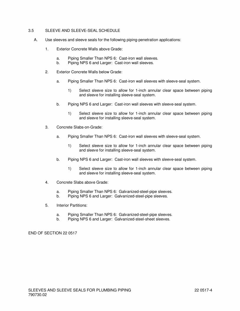
3.5 SLEEVE AND SLEEVE-SEAL SCHEDULE
A. Use sleeves and sleeve seals for the following piping-penetration applications:
1. Exterior Concrete Walls above Grade:
a. Piping Smaller Than NPS 6: Cast-iron wall sleeves. b. Piping NPS 6 and Larger: Cast-iron wall sleeves.
2. Exterior Concrete Walls below Grade:
a. Piping Smaller Than NPS 6: Cast-iron wall sleeves with sleeve-seal system.
1) Select sleeve size to allow for 1-inch annular clear space between piping and sleeve for installing sleeve-seal system.
b. Piping NPS 6 and Larger: Cast-iron wall sleeves with sleeve-seal system.
1) Select sleeve size to allow for 1-inch annular clear space between piping and sleeve for installing sleeve-seal system.
3. Concrete Slabs-on-Grade:
a. Piping Smaller Than NPS 6: Cast-iron wall sleeves with sleeve-seal system.
1) Select sleeve size to allow for 1-inch annular clear space between piping and sleeve for installing sleeve-seal system.
b. Piping NPS 6 and Larger: Cast-iron wall sleeves with sleeve-seal system.
1) Select sleeve size to allow for 1-inch annular clear space between piping and sleeve for installing sleeve-seal system.
4. Concrete Slabs above Grade:
a. Piping Smaller Than NPS 6: Galvanized-steel-pipe sleeves. b. Piping NPS 6 and Larger: Galvanized-steel-pipe sleeves.
5. Interior Partitions:
a. Piping Smaller Than NPS 6: Galvanized-steel-pipe sleeves. b. Piping NPS 6 and Larger: Galvanized-steel-sheet sleeves.
END OF SECTION 22 0517

ESCUTCHEONS FOR PLUMBING PIPING 790730.02
220518 - 1
SECTION 22 0518 - ESCUTCHEONS FOR PLUMBING PIPING
PART 1 - GENERAL
1.1 RELATED DOCUMENTS
A. Drawings and general provisions of the Contract, including General and Supplementary Conditions and Division 01 Specification Sections, apply to this Section.
1.2 SUMMARY
A. Section Includes:
1. Escutcheons. 2. Floor plates.
1.3 ACTION SUBMITTALS
A. Product Data: For each type of product indicated.
PART 2 - PRODUCTS
2.1 ESCUTCHEONS
A. One-Piece, Cast-Brass Type: With polished, chrome-plated finish and setscrew fastener.
B. One-Piece, Deep-Pattern Type: Deep-drawn, box-shaped brass with chrome-plated finish and spring-clip fasteners.
C. One-Piece, Stamped-Steel Type: With chrome-plated finish and spring-clip fasteners.
D. Split-Casting Brass Type: With polished, chrome-plated finish and with concealed hinge and setscrew.
E. Split-Plate, Stamped-Steel Type: With chrome-plated finish, concealed hinge, and spring-clip fasteners.
2.2 FLOOR PLATES
A. One-Piece Floor Plates: Cast-iron flange with holes for fasteners.
B. Split-Casting Floor Plates: Cast brass with concealed hinge.
ESCUTCHEONS FOR PLUMBING PIPING 790730.02
220518 - 2
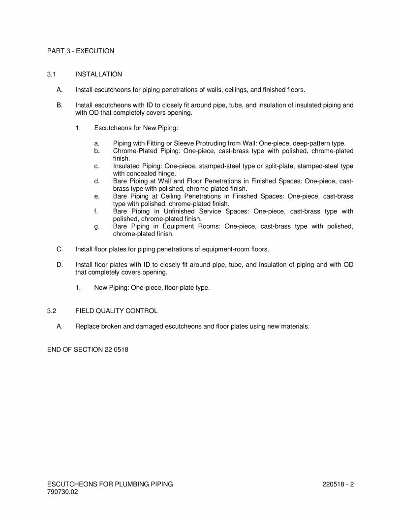
PART 3 - EXECUTION
3.1 INSTALLATION
A. Install escutcheons for piping penetrations of walls, ceilings, and finished floors.
B. Install escutcheons with ID to closely fit around pipe, tube, and insulation of insulated piping and with OD that completely covers opening.
1. Escutcheons for New Piping:
a. Piping with Fitting or Sleeve Protruding from Wall: One-piece, deep-pattern type. b. Chrome-Plated Piping: One-piece, cast-brass type with polished, chrome-plated
finish. c. Insulated Piping: One-piece, stamped-steel type or split-plate, stamped-steel type
with concealed hinge. d. Bare Piping at Wall and Floor Penetrations in Finished Spaces: One-piece, cast-
brass type with polished, chrome-plated finish. e. Bare Piping at Ceiling Penetrations in Finished Spaces: One-piece, cast-brass
type with polished, chrome-plated finish. f. Bare Piping in Unfinished Service Spaces: One-piece, cast-brass type with
polished, chrome-plated finish. g. Bare Piping in Equipment Rooms: One-piece, cast-brass type with polished,
chrome-plated finish.
C. Install floor plates for piping penetrations of equipment-room floors.
D. Install floor plates with ID to closely fit around pipe, tube, and insulation of piping and with OD that completely covers opening.
1. New Piping: One-piece, floor-plate type.
3.2 FIELD QUALITY CONTROL
A. Replace broken and damaged escutcheons and floor plates using new materials.
END OF SECTION 22 0518
BALL VALVES FOR PLUMBING PIPING 790730.02
220523.12 - 1
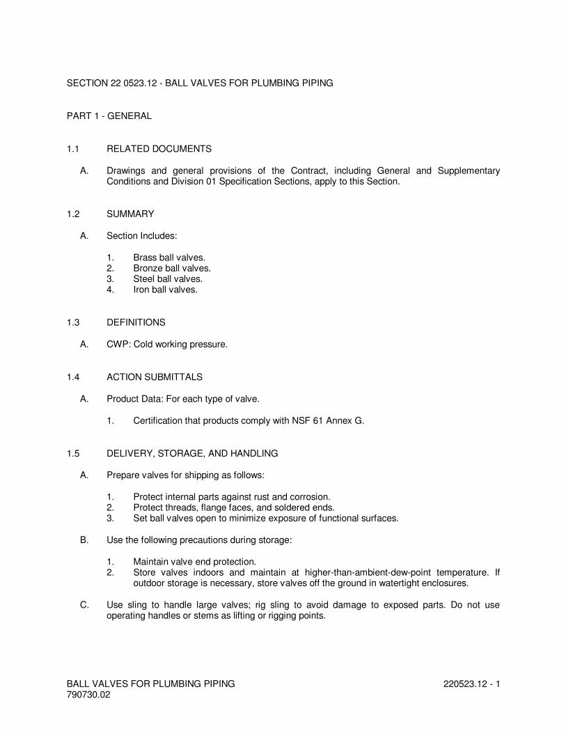
SECTION 22 0523.12 - BALL VALVES FOR PLUMBING PIPING
PART 1 - GENERAL
1.1 RELATED DOCUMENTS
A. Drawings and general provisions of the Contract, including General and Supplementary Conditions and Division 01 Specification Sections, apply to this Section.
1.2 SUMMARY
A. Section Includes:
1. Brass ball valves. 2. Bronze ball valves. 3. Steel ball valves. 4. Iron ball valves.
1.3 DEFINITIONS
A. CWP: Cold working pressure.
1.4 ACTION SUBMITTALS
A. Product Data: For each type of valve.
1. Certification that products comply with NSF 61 Annex G.
1.5 DELIVERY, STORAGE, AND HANDLING
A. Prepare valves for shipping as follows:
1. Protect internal parts against rust and corrosion. 2. Protect threads, flange faces, and soldered ends. 3. Set ball valves open to minimize exposure of functional surfaces.
B. Use the following precautions during storage:
1. Maintain valve end protection. 2. Store valves indoors and maintain at higher-than-ambient-dew-point temperature. If
outdoor storage is necessary, store valves off the ground in watertight enclosures.
C. Use sling to handle large valves; rig sling to avoid damage to exposed parts. Do not use operating handles or stems as lifting or rigging points.
BALL VALVES FOR PLUMBING PIPING 790730.02
220523.12 - 2
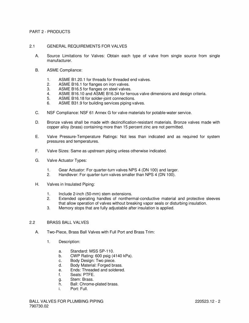
PART 2 - PRODUCTS
2.1 GENERAL REQUIREMENTS FOR VALVES
A. Source Limitations for Valves: Obtain each type of valve from single source from single manufacturer.
B. ASME Compliance:
1. ASME B1.20.1 for threads for threaded end valves. 2. ASME B16.1 for flanges on iron valves. 3. ASME B16.5 for flanges on steel valves. 4. ASME B16.10 and ASME B16.34 for ferrous valve dimensions and design criteria. 5. ASME B16.18 for solder-joint connections. 6. ASME B31.9 for building services piping valves.
C. NSF Compliance: NSF 61 Annex G for valve materials for potable-water service.
D. Bronze valves shall be made with dezincification-resistant materials. Bronze valves made with copper alloy (brass) containing more than 15 percent zinc are not permitted.
E. Valve Pressure-Temperature Ratings: Not less than indicated and as required for system pressures and temperatures.
F. Valve Sizes: Same as upstream piping unless otherwise indicated.
G. Valve Actuator Types:
1. Gear Actuator: For quarter-turn valves NPS 4 (DN 100) and larger. 2. Handlever: For quarter-turn valves smaller than NPS 4 (DN 100).
H. Valves in Insulated Piping:
1. Include 2-inch (50-mm) stem extensions. 2. Extended operating handles of nonthermal-conductive material and protective sleeves
that allow operation of valves without breaking vapor seals or disturbing insulation. 3. Memory stops that are fully adjustable after insulation is applied.
2.2 BRASS BALL VALVES
A. Two-Piece, Brass Ball Valves with Full Port and Brass Trim:
1. Description:
a. Standard: MSS SP-110. b. CWP Rating: 600 psig (4140 kPa). c. Body Design: Two piece. d. Body Material: Forged brass. e. Ends: Threaded and soldered. f. Seats: PTFE. g. Stem: Brass. h. Ball: Chrome-plated brass. i. Port: Full.
BALL VALVES FOR PLUMBING PIPING 790730.02
220523.12 - 3
B. Two-Piece, Brass Ball Valves with Full Port and Stainless-Steel Trim:
1. Description:
a. Standard: MSS SP-110. b. CWP Rating: 600 psig (4140 kPa). c. Body Design: Two piece. d. Body Material: Forged brass. e. Ends: Threaded and soldered. f. Seats: PTFE. g. Stem: Stainless steel. h. Ball: Stainless steel, vented. i. Port: Full.
2.3 BRONZE BALL VALVES
A. Two-Piece, Bronze Ball Valves with Full Port, and Bronze or Brass Trim:
1. Description:
a. Standard: MSS SP-110. b. CWP Rating: 600 psig (4140 kPa). c. Body Design: Two piece. d. Body Material: Bronze. e. Ends: Threaded and soldered. f. Seats: PTFE. g. Stem: Bronze or brass. h. Ball: Chrome-plated brass. i. Port: Full.
B. Two-Piece, Bronze Ball Valves with Full Port and Stainless-Steel Trim:
1. Description:
a. Standard: MSS SP-110. b. CWP Rating: 600 psig (4140 kPa). c. Body Design: Two piece. d. Body Material: Bronze. e. Ends: Threaded or soldered. f. Seats: PTFE. g. Stem: Stainless steel. h. Ball: Stainless steel, vented. i. Port: Full.
PART 3 - EXECUTION
3.1 EXAMINATION
A. Examine valve interior for cleanliness, freedom from foreign matter, and corrosion. Remove special packing materials, such as blocks, used to prevent disc movement during shipping and handling.

BALL VALVES FOR PLUMBING PIPING 790730.02
220523.12 - 4
B. Operate valves in positions from fully open to fully closed. Examine guides and seats made accessible by such operations.
C. Examine threads on valve and mating pipe for form and cleanliness.
D. Examine mating flange faces for conditions that might cause leakage. Check bolting for proper size, length, and material. Verify that gasket is of proper size, that its material composition is suitable for service, and that it is free from defects and damage.
E. Do not attempt to repair defective valves; replace with new valves.
3.2 VALVE INSTALLATION
A. Install valves with unions or flanges at each piece of equipment arranged to allow service, maintenance, and equipment removal without system shutdown.
B. Locate valves for easy access and provide separate support where necessary.
C. Install valves in horizontal piping with stem at or above center of pipe.
D. Install valves in position to allow full stem movement.
E. Install valve tags. Comply with requirements in Section 220553 "Identification for Plumbing Piping and Equipment" for valve tags and schedules.
3.3 GENERAL REQUIREMENTS FOR VALVE APPLICATIONS
A. If valves with specified CWP ratings are unavailable, the same types of valves with higher CWP ratings may be substituted.
B. Select valves with the following end connections:
1. For Copper Tubing, NPS 2 (DN 50) and Smaller: Threaded ends except where solder-joint valve-end option is indicated in valve schedules below.
2. For Copper Tubing, NPS 2-1/2 to NPS 4 (DN 65 to DN 100): Flanged ends except where threaded valve-end option is indicated in valve schedules below.
3. For Copper Tubing, NPS 5 (DN 125) and Larger: Flanged ends. 4. For Steel Piping, NPS 2 (DN 50) and Smaller: Threaded ends. 5. For Steel Piping, NPS 2-1/2 to NPS 4 (DN 65 to DN 100): Flanged ends except where
threaded valve-end option is indicated in valve schedules below. 6. For Steel Piping, NPS 5 (DN 125) and Larger: Flanged ends.
3.4 DOMESTIC HOT- AND COLD-WATER VALVE SCHEDULE
A. Pipe NPS 2 (DN 50) and Smaller:
1. Bronze and Brass Valves: May be provided with solder-joint ends instead of threaded ends.
2. Two-piece, brass ball valves with full port and brass trim. 3. Two-piece, bronze ball valves with full port and bronze or brass trim.
B. Pipe NPS 2-1/2 (DN 65) and Larger:
BALL VALVES FOR PLUMBING PIPING 790730.02
220523.12 - 5
1. Steel and Iron Valves, NPS 2-1/2 to NPS 4 (DN 65 to DN 100): May be provided with threaded ends instead of flanged ends.
2. Class 150, steel ball valves with full port. 3. Class 150, iron ball valves.
END OF SECTION 22 0523.12

BALL VALVES FOR PLUMBING PIPING 790730.02
220523.12 - 6

CHECK VALVES FOR PLUMBING PIPING 790730.02
22 0523.14 - 1
SECTION 22 0523.14 - CHECK VALVES FOR PLUMBING PIPING
PART 1 - GENERAL
1.1 RELATED DOCUMENTS
A. Drawings and general provisions of the Contract, including General and Supplementary Conditions and Division 01 Specification Sections, apply to this Section.
1.2 SUMMARY
A. Section Includes:
1. Bronze lift check valves. 2. Bronze swing check valves. 3. Iron swing check valves. 4. Iron swing check valves with closure control. 5. Iron, grooved-end swing check valves. 6. Iron, center-guided check valves. 7. Iron, plate-type check valves.
1.3 DEFINITIONS
A. CWP: Cold working pressure.
B. EPDM: Ethylene propylene-diene terpolymer rubber.
C. NBR: Acrylonitrile-butadiene, Buna-N, or nitrile rubber.
1.4 ACTION SUBMITTALS
A. Product Data: For each type of valve.
1. Certification that products comply with NSF 61 Annex G.
1.5 DELIVERY, STORAGE, AND HANDLING
A. Prepare valves for shipping as follows:
1. Protect internal parts against rust and corrosion. 2. Protect threads, flange faces, grooves, and weld ends. 3. Set check valves in either closed or open position.
B. Use the following precautions during storage:
1. Maintain valve end protection. 2. Store valves indoors and maintain at higher-than-ambient-dew-point temperature. If
outdoor storage is necessary, store valves off the ground in watertight enclosures.
CHECK VALVES FOR PLUMBING PIPING 790730.02
22 0523.14 - 2
C. Use sling to handle large valves; rig sling to avoid damage to exposed parts. Do not use handwheels or stems as lifting or rigging points.
PART 2 - PRODUCTS
2.1 GENERAL REQUIREMENTS FOR VALVES
A. Source Limitations for Valves: Obtain each type of valve from single source from single manufacturer.
B. ASME Compliance:
1. ASME B1.20.1 for threads for threaded end valves. 2. ASME B16.1 for flanges on iron valves. 3. ASME B16.10 and ASME B16.34 for ferrous valve dimensions and design criteria. 4. ASME B16.18 for solder joint. 5. ASME B31.9 for building services piping valves.
C. AWWA Compliance: Comply with AWWA C606 for grooved-end connections.
D. NSF Compliance: NSF 61 Annex G for valve materials for potable-water service.
E. Bronze valves shall be made with dezincification-resistant materials. Bronze valves made with copper alloy (brass) containing more than 15 percent zinc are not permitted.
F. Valve Pressure-Temperature Ratings: Not less than indicated and as required for system pressures and temperatures.
G. Valve Sizes: Same as upstream piping unless otherwise indicated.
H. Valve Bypass and Drain Connections: MSS SP-45.
2.2 BRONZE LIFT CHECK VALVES
A. Class 150, Bronze Swing Check Valves with Bronze Disc:
1. Description:
a. Standard: MSS SP-80, Type 3. b. CWP Rating: 300 psig (2070 kPa). c. Body Design: Horizontal flow. d. Body Material: ASTM B 62, bronze. e. Ends: Threaded or soldered. See valve schedule articles. f. Disc: Bronze.
B. Class 150, Bronze Swing Check Valves with Nonmetallic Disc:
1. Description:
a. Standard: MSS SP-80, Type 4. b. CWP Rating: 300 psig (2070 kPa). c. Body Design: Horizontal flow.

CHECK VALVES FOR PLUMBING PIPING 790730.02
22 0523.14 - 3
d. Body Material: ASTM B 62, bronze. e. Ends: Threaded or soldered. See valve schedule articles. f. Disc: PTFE.
2.3 IRON SWING CHECK VALVES
A. Class 125, Iron Swing Check Valves with Metal Seats:
1. Description:
a. Standard: MSS SP-71, Type I. b. CWP Rating: 200 psig (1380 kPa). c. Body Design: Clear or full waterway. d. Body Material: ASTM A 126, gray iron with bolted bonnet. e. Ends: Flanged or threaded. See valve schedule articles. f. Trim: Bronze. g. Gasket: Asbestos free.
B. Class 125, Iron Swing Check Valves with Nonmetallic-to-Metal Seats:
1. Description:
a. Standard: MSS SP-71, Type I. b. CWP Rating: 200 psig (1380 kPa). c. Body Design: Clear or full waterway. d. Body Material: ASTM A 126, gray iron with bolted bonnet. e. Ends: Flanged or threaded. See valve schedule articles. f. Trim: Composition. g. Seat Ring: Bronze. h. Disc Holder: Bronze. i. Disc: PTFE. j. Gasket: Asbestos free.
PART 3 - EXECUTION
3.1 EXAMINATION
A. Examine valve interior for cleanliness, freedom from foreign matter, and corrosion. Remove special packing materials, such as blocks, used to prevent disc movement during shipping and handling.
B. Operate valves in positions from fully open to fully closed. Examine guides and seats made accessible by such operations.
C. Examine threads on valve and mating pipe for form and cleanliness.
D. Examine mating flange faces for conditions that might cause leakage. Check bolting for proper size, length, and material. Verify that gasket is of proper size, that its material composition is suitable for service, and that it is free from defects and damage.
E. Do not attempt to repair defective valves; replace with new valves.

CHECK VALVES FOR PLUMBING PIPING 790730.02
22 0523.14 - 4
3.2 VALVE INSTALLATION
A. Install valves with unions or flanges at each piece of equipment arranged to allow service, maintenance, and equipment removal without system shutdown.
B. Locate valves for easy access and provide separate support where necessary.
C. Install valves in horizontal piping with stem at or above center of pipe.
D. Install valves in position to allow full stem movement.
E. Install check valves for proper direction of flow and as follows:
1. Swing Check Valves: In horizontal position with hinge pin level. 2. Center-Guided and Plate-Type Check Valves: In horizontal or vertical position, between
flanges. 3. Lift Check Valves: With stem upright and plumb.
F. Install valve tags. Comply with requirements in Section 220553 "Identification for Plumbing Piping and Equipment" for valve tags and schedules.
3.3 ADJUSTING
A. Adjust or replace valve packing after piping systems have been tested and put into service but before final adjusting and balancing. Replace valves if persistent leaking occurs.
3.4 GENERAL REQUIREMENTS FOR VALVE APPLICATIONS
A. If valve applications are not indicated, use the following:
1. Pump-Discharge Check Valves:
a. NPS 2 (DN 50) and Smaller: Bronze swing check valves with bronze or nonmetallic disc.
b. NPS 2-1/2 (DN 65) and Larger for Domestic Water: Iron swing check valves with lever and weight or spring; or iron, center-guided, metal-seat or resilient-seat check valves.
c. NPS 2-1/2 (DN 65) and Larger for Sanitary Waste and Storm Drainage: Iron swing check valves with lever and weight or spring.
B. If valves with specified CWP ratings are unavailable, the same types of valves with higher CWP ratings may be substituted.
C. End Connections:
1. For Copper Tubing, NPS 2 (DN 50) and Smaller: Threaded or soldered. 2. For Copper Tubing, NPS 2-1/2 to NPS 4 (DN 65 to DN 100): Flanged or threaded. 3. For Copper Tubing, NPS 5 (DN 125) and Larger: Flanged. 4. For Steel Piping, NPS 2 (DN 50) and Smaller: Threaded. 5. For Steel Piping, NPS 2-1/2 to NPS 4 (DN 65 to DN 100): Flanged or threaded. 6. For Steel Piping, NPS 5 (DN 125) and Larger: Flanged. 7. For Grooved-End Copper Tubing: Grooved.
CHECK VALVES FOR PLUMBING PIPING 790730.02
22 0523.14 - 5
3.5 DOMESTIC HOT- AND COLD-WATER VALVE SCHEDULE
A. Pipe NPS 2 (DN 50) and Smaller: Bronze swing check valves, Class 150, bronze disc with soldered or threaded end connections.
B. Pipe NPS 2-1/2 (DN 65) and Larger:
1. Iron swing check valves, Class 125, seats with threaded or flanged end connections. 2. Iron swing check valves with closure control, Class 125, lever and spring with threaded or
flanged end connections. 3. Iron, grooved-end swing check valves, 300 CWP. 4. Iron, center-guided check valves, Class 125, compact wafer. 5. Iron, center-guided check valves, Class 125,, resilient seat with threaded or flanged end
connections. 6. Iron, dual-plate check valves, Class 125, resilient seat with threaded or flanged end
connections. 7. Iron, single-plate check valves, Class 125, resilient seat with threaded or flanged end
connections.
END OF SECTION 22 0523.14

CHECK VALVES FOR PLUMBING PIPING 790730.02
22 0523.14 - 6
HANGERS AND SUPPORTS FOR PLUMBING PIPING AND EQUIPMENT 790730.02
22 0529-1
SECTION 22 0529 - HANGERS AND SUPPORTS FOR PLUMBING PIPING AND EQUIPMENT
PART 1 - GENERAL
1.1 RELATED DOCUMENTS
A. Drawings and general provisions of the Contract, including General and Supplementary Conditions and Division 01 Specification Sections, apply to this Section.
1.2 SUMMARY
A. Section Includes:
1. Metal pipe hangers and supports. 2. Trapeze pipe hangers 3. Metal framing systems. 4. Thermal-hanger shield inserts. 5. Fastener systems. 6. Pipe stands. 7. Pipe positioning systems.
B. Related Sections:
1. Section 055000 "Metal Fabrications" for structural-steel shapes and plates for trapeze hangers for pipe and equipment supports.
2. Section 220516 "Expansion Fittings and Loops for Plumbing Piping" for pipe guides and anchors.
3. Section 220548 "Vibration and Seismic Controls for Plumbing Piping and Equipment" for vibration isolation devices.
1.3 DEFINITIONS
A. MSS: Manufacturers Standardization Society of The Valve and Fittings Industry Inc.
1.4 PERFORMANCE REQUIREMENTS
A. Delegated Design: Design trapeze pipe hangers and equipment supports, including comprehensive engineering analysis by a qualified professional engineer, using performance requirements and design criteria indicated.
B. Structural Performance: Hangers and supports for plumbing piping and equipment shall withstand the effects of gravity loads and stresses within limits and under conditions indicated according to ASCE/SEI 7.
1. Design supports for multiple pipes, including pipe stands, capable of supporting combined weight of supported systems, system contents, and test water.
2. Design equipment supports capable of supporting combined operating weight of supported equipment and connected systems and components.
3. Design seismic-restraint hangers and supports for piping and equipment.

HANGERS AND SUPPORTS FOR PLUMBING PIPING AND EQUIPMENT 790730.02
22 0529-2
1.5 ACTION SUBMITTALS
A. Product Data: For each type of product indicated.
B. Shop Drawings: Signed and sealed by a qualified professional engineer. Show fabrication and installation details and include calculations for the following; include Product Data for components:
1. Trapeze pipe hangers. 2. Metal framing systems. 3. Fiberglass strut systems. 4. Pipe stands. 5. Equipment supports.
C. Delegated-Design Submittal: For trapeze hangers indicated to comply with performance requirements and design criteria, including analysis data signed and sealed by the qualified professional engineer responsible for their preparation.
1. Detail fabrication and assembly of trapeze hangers. 2. Design Calculations: Calculate requirements for designing trapeze hangers.
1.6 INFORMATIONAL SUBMITTALS
A. Welding certificates.
1.7 QUALITY ASSURANCE
A. Structural Steel Welding Qualifications: Qualify procedures and personnel according to AWS D1.1/D1.1M, "Structural Welding Code - Steel."
B. Pipe Welding Qualifications: Qualify procedures and operators according to ASME Boiler and Pressure Vessel Code.
PART 2 - PRODUCTS
2.1 METAL PIPE HANGERS AND SUPPORTS
A. Carbon-Steel Pipe Hangers and Supports:
1. Description: MSS SP-58, Types 1 through 58, factory-fabricated components. 2. Galvanized Metallic Coatings: Pre-galvanized or hot dipped. 3. Nonmetallic Coatings: Plastic coating, jacket, or liner. 4. Padded Hangers: Hanger with fiberglass or other pipe insulation pad or cushion to
support bearing surface of piping. 5. Hanger Rods: Continuous-thread rod, nuts, and washer made of stainless steel.
B. Stainless-Steel Pipe Hangers and Supports:
1. Description: MSS SP-58, Types 1 through 58, factory-fabricated components. 2. Padded Hangers: Hanger with fiberglass or other pipe insulation pad or cushion to
support bearing surface of piping.
HANGERS AND SUPPORTS FOR PLUMBING PIPING AND EQUIPMENT 790730.02
22 0529-3
3. Hanger Rods: Continuous-thread rod, nuts, and washer made of stainless steel.
C. Copper Pipe Hangers:
1. Description: MSS SP-58, Types 1 through 58, copper-coated-steel, factory-fabricated components.
2. Hanger Rods: Continuous-thread rod, nuts, and washer made of stainless steel.
2.2 TRAPEZE PIPE HANGERS
A. Description: MSS SP-69, Type 59, shop- or field-fabricated pipe-support assembly made from structural carbon-steel shapes with MSS SP-58 carbon-steel hanger rods, nuts, saddles, and U-bolts.
2.3 METAL FRAMING SYSTEMS
A. MFMA Manufacturer Metal Framing Systems:
1. Description: Shop- or field-fabricated pipe-support assembly for supporting multiple parallel pipes.
2. Standard: MFMA-4. 3. Channels: Continuous slotted steel channel with inturned lips. 4. Channel Nuts: Formed or stamped steel nuts or other devices designed to fit into channel
slot and, when tightened, prevent slipping along channel. 5. Hanger Rods: Continuous-thread rod, nuts, and washer made of stainless steel.
B. Non-MFMA Manufacturer Metal Framing Systems:
1. Description: Shop- or field-fabricated pipe-support assembly made of steel channels, accessories, fittings, and other components for supporting multiple parallel pipes.
2. Standard: Comply with MFMA-4. 3. Channels: Continuous slotted steel channel with inturned lips. 4. Channel Nuts: Formed or stamped steel nuts or other devices designed to fit into channel
slot and, when tightened, prevent slipping along channel. 5. Hanger Rods: Continuous-thread rod, nuts, and washer made of stainless steel.
2.4 THERMAL-HANGER SHIELD INSERTS
A. Insulation-Insert Material for Cold Piping: ASTM C 552, Type II cellular glass with 100-psig or ASTM C 591, Type VI, Grade 1 polyisocyanurate with 125-psig minimum compressive strength and vapor barrier.
B. Insulation-Insert Material for Hot Piping: Water-repellent treated, ASTM C 533, Type I calcium silicate with 100-psig or ASTM C 591, Type VI, Grade 1 polyisocyanurate with 125-psig minimum compressive strength.
C. For Trapeze or Clamped Systems: Insert and shield shall cover entire circumference of pipe.
D. For Clevis or Band Hangers: Insert and shield shall cover lower 180 degrees of pipe.
E. Insert Length: Extend 2 inches beyond sheet metal shield for piping operating below ambient air temperature.
HANGERS AND SUPPORTS FOR PLUMBING PIPING AND EQUIPMENT 790730.02
22 0529-4
2.5 FASTENER SYSTEMS
A. Powder-Actuated Fasteners: Threaded-steel stud, for use in hardened portland cement concrete with pull-out, tension, and shear capacities appropriate for supported loads and building materials where used.
B. Mechanical-Expansion Anchors: Insert-wedge-type, stainless- steel anchors, for use in hardened portland cement concrete; with pull-out, tension, and shear capacities appropriate for supported loads and building materials where used.
2.6 PIPE STANDS
A. General Requirements for Pipe Stands: Shop- or field-fabricated assemblies made of manufactured corrosion-resistant components to support roof-mounted piping.
B. Compact Pipe Stand: One-piece plastic unit with integral-rod roller, pipe clamps, or V-shaped cradle to support pipe, for roof installation without membrane penetration.
C. Low-Type, Single-Pipe Stand: One-piece plastic base unit with plastic roller, for roof installation without membrane penetration.
D. High-Type, Single-Pipe Stand:
1. Description: Assembly of base, vertical and horizontal members, and pipe support, for roof installation without membrane penetration.
2. Base: Stainless steel. 3. Vertical Members: Two or more cadmium-plated-steel or stainless-steel, continuous-
thread rods. 4. Horizontal Member: Cadmium-plated-steel or stainless-steel rod with plastic or stainless-
steel, roller-type pipe support.
E. High-Type, Multiple-Pipe Stand:
1. Description: Assembly of bases, vertical and horizontal members, and pipe supports, for roof installation without membrane penetration.
2. Bases: One or more; plastic. 3. Vertical Members: Two or more protective-coated-steel channels. 4. Horizontal Member: Protective-coated-steel channel. 5. Pipe Supports: Galvanized-steel, clevis-type pipe hangers.
F. Curb-Mounting-Type Pipe Stands: Shop- or field-fabricated pipe supports made from structural-steel shapes, continuous-thread rods, and rollers, for mounting on permanent stationary roof curb.
2.7 PIPE POSITIONING SYSTEMS
A. Description: IAPMO PS 42, positioning system of metal brackets, clips, and straps for positioning piping in pipe spaces; for plumbing fixtures in commercial applications.

HANGERS AND SUPPORTS FOR PLUMBING PIPING AND EQUIPMENT 790730.02
22 0529-5
2.8 EQUIPMENT SUPPORTS
A. Description: Welded, shop- or field-fabricated equipment support made from structural carbon-steel shapes.
2.9 MISCELLANEOUS MATERIALS
A. Structural Steel: ASTM A 36/A 36M, carbon-steel plates, shapes, and bars; black and galvanized.
B. Grout: ASTM C 1107, factory-mixed and -packaged, dry, hydraulic-cement, nonshrink and nonmetallic grout; suitable for interior and exterior applications.
1. Properties: Nonstaining, noncorrosive, and nongaseous. 2. Design Mix: 5000-psi, 28-day compressive strength.
PART 3 - EXECUTION
3.1 HANGER AND SUPPORT INSTALLATION
A. Metal Pipe-Hanger Installation: Comply with MSS SP-69 and MSS SP-89. Install hangers, supports, clamps, and attachments as required to properly support piping from the building structure.
B. Metal Trapeze Pipe-Hanger Installation: Comply with MSS SP-69 and MSS SP-89. Arrange for grouping of parallel runs of horizontal piping, and support together on field-fabricated trapeze pipe hangers.
1. Pipes of Various Sizes: Support together and space trapezes for smallest pipe size or install intermediate supports for smaller diameter pipes as specified for individual pipe hangers.
2. Field fabricate from ASTM A 36/A 36M, carbon-steel shapes selected for loads being supported. Weld steel according to AWS D1.1/D1.1M.
C. Fiberglass Pipe-Hanger Installation: Comply with applicable portions of MSS SP-69 and MSS SP-89. Install hangers and attachments as required to properly support piping from building structure.
D. Metal Framing System Installation: Arrange for grouping of parallel runs of piping, and support together on field-assembled metal framing systems.
E. Fiberglass Strut System Installation: Arrange for grouping of parallel runs of piping, and support together on field-assembled fiberglass struts.
F. Thermal-Hanger Shield Installation: Install in pipe hanger or shield for insulated piping.
G. Fastener System Installation:
1. Install powder-actuated fasteners for use in lightweight concrete or concrete slabs less than 4 inches thick in concrete after concrete is placed and completely cured. Use operators that are licensed by powder-actuated tool manufacturer. Install fasteners according to powder-actuated tool manufacturer's operating manual.
HANGERS AND SUPPORTS FOR PLUMBING PIPING AND EQUIPMENT 790730.02
22 0529-6
2. Install mechanical-expansion anchors in concrete after concrete is placed and completely cured. Install fasteners according to manufacturer's written instructions.
H. Pipe Stand Installation:
1. Pipe Stand Types except Curb-Mounted Type: Assemble components and mount on smooth roof surface. Do not penetrate roof membrane.
2. Curb-Mounted-Type Pipe Stands: Assemble components or fabricate pipe stand and mount on permanent, stationary roof curb. See Section 077200 "Roof Accessories" for curbs.
I. Pipe Positioning-System Installation: Install support devices to make rigid supply and waste piping connections to each plumbing fixture.
J. Install hangers and supports complete with necessary attachments, inserts, bolts, rods, nuts, washers, and other accessories.
K. Equipment Support Installation: Fabricate from welded-structural-steel shapes.
L. Install hangers and supports to allow controlled thermal and seismic movement of piping systems, to permit freedom of movement between pipe anchors, and to facilitate action of expansion joints, expansion loops, expansion bends, and similar units.
M. Install lateral bracing with pipe hangers and supports to prevent swaying.
N. Install building attachments within concrete slabs or attach to structural steel. Install additional attachments at concentrated loads, including valves, flanges, and strainers, NPS 2-1/2 and larger and at changes in direction of piping. Install concrete inserts before concrete is placed; fasten inserts to forms and install reinforcing bars through openings at top of inserts.
O. Load Distribution: Install hangers and supports so that piping live and dead loads and stresses from movement will not be transmitted to connected equipment.
P. Pipe Slopes: Install hangers and supports to provide indicated pipe slopes and to not exceed maximum pipe deflections allowed by ASME B31.9 for building services piping.
Q. Insulated Piping:
1. Attach clamps and spacers to piping.
a. Piping Operating Above Ambient Air Temperature: Clamp may project through insulation.
b. Piping Operating Below Ambient Air Temperature: Use thermal-hanger shield insert with clamp sized to match OD of insert.
c. Do not exceed pipe stress limits allowed by ASME B31.9 for building services piping.
2. Install MSS SP-58, Type 39, protection saddles if insulation without vapor barrier is indicated. Fill interior voids with insulation that matches adjoining insulation.
a. Option: Thermal-hanger shield inserts may be used. Include steel weight-distribution plate for pipe NPS 4 and larger if pipe is installed on rollers.
3. Install MSS SP-58, Type 40, protective shields on cold piping with vapor barrier. Shields shall span an arc of 180 degrees.
HANGERS AND SUPPORTS FOR PLUMBING PIPING AND EQUIPMENT 790730.02
22 0529-7
a. Option: Thermal-hanger shield inserts may be used. Include steel weight-distribution plate for pipe NPS 4 and larger if pipe is installed on rollers.
4. Shield Dimensions for Pipe: Not less than the following:
a. NPS 1/4 to NPS 3-1/2: 12 inches long and 0.048 inch thick. b. NPS 4: 12 inches long and 0.06 inch thick. c. NPS 5 and NPS 6: 18 inches long and 0.06 inch thick. d. NPS 8 to NPS 14: 24 inches long and 0.075 inch thick. e. NPS 16 to NPS 24: 24 inches long and 0.105 inch thick.
5. Pipes NPS 8 and Larger: Include wood or reinforced calcium-silicate-insulation inserts of length at least as long as protective shield.
6. Thermal-Hanger Shields: Install with insulation same thickness as piping insulation.
3.2 EQUIPMENT SUPPORTS
A. Fabricate structural-steel stands to suspend equipment from structure overhead or to support equipment above floor.
B. Grouting: Place grout under supports for equipment and make bearing surface smooth.
C. Provide lateral bracing, to prevent swaying, for equipment supports.
3.3 METAL FABRICATIONS
A. Cut, drill, and fit miscellaneous metal fabrications for trapeze pipe hangers.
B. Fit exposed connections together to form hairline joints. Field weld connections that cannot be shop welded because of shipping size limitations.
C. Field Welding: Comply with AWS D1.1/D1.1M procedures for shielded, metal arc welding; appearance and quality of welds; and methods used in correcting welding work; and with the following:
1. Use materials and methods that minimize distortion and develop strength and corrosion resistance of base metals.
2. Obtain fusion without undercut or overlap. 3. Remove welding flux immediately. 4. Finish welds at exposed connections so no roughness shows after finishing and so
contours of welded surfaces match adjacent contours.
3.4 ADJUSTING
A. Hanger Adjustments: Adjust hangers to distribute loads equally on attachments and to achieve indicated slope of pipe.
B. Trim excess length of continuous-thread hanger and support rods to 1-1/2 inches.

HANGERS AND SUPPORTS FOR PLUMBING PIPING AND EQUIPMENT 790730.02
22 0529-8
3.5 PAINTING
A. Touchup: Clean field welds and abraded areas of shop paint. Paint exposed areas immediately after erecting hangers and supports. Use same materials as used for shop painting. Comply with SSPC-PA 1 requirements for touching up field-painted surfaces.
1. Apply paint by brush or spray to provide a minimum dry film thickness of 2.0 mils.
B. Galvanized Surfaces: Clean welds, bolted connections, and abraded areas and apply galvanizing-repair paint to comply with ASTM A 780.
3.6 HANGER AND SUPPORT SCHEDULE
A. Specific hanger and support requirements are in Sections specifying piping systems and equipment.
B. Comply with MSS SP-69 for pipe-hanger selections and applications that are not specified in piping system Sections.
C. Use hangers and supports with galvanized metallic coatings for piping and equipment that will not have field-applied finish.
D. Use nonmetallic coatings on attachments for electrolytic protection where attachments are in direct contact with copper tubing.
E. Use carbon-steel pipe hangers and supports and metal framing systems and attachments for general service applications.
F. Use stainless-steel pipe hangers and stainless-steel attachments for hostile environment applications.
G. Use copper-plated pipe hangers and stainless-steel attachments for copper piping and tubing.
H. Use padded hangers for piping that is subject to scratching.
I. Use thermal-hanger shield inserts for insulated piping and tubing.
J. Horizontal-Piping Hangers and Supports: Unless otherwise indicated and except as specified in piping system Sections, install the following types:
1. Adjustable, Steel Clevis Hangers (MSS Type 1): For suspension of noninsulated or insulated, stationary pipes NPS 1/2 to NPS 30.
2. Yoke-Type Pipe Clamps (MSS Type 2): For suspension of up to 1050 deg F, pipes NPS 4 to NPS 24, requiring up to 4 inches of insulation.
3. Carbon- or Alloy-Steel, Double-Bolt Pipe Clamps (MSS Type 3): For suspension of pipes NPS 3/4 to NPS 36, requiring clamp flexibility and up to 4 inches of insulation.
4. Steel Pipe Clamps (MSS Type 4): For suspension of cold and hot pipes NPS 1/2 to NPS 24 if little or no insulation is required.
5. Pipe Hangers (MSS Type 5): For suspension of pipes NPS 1/2 to NPS 4, to allow off-center closure for hanger installation before pipe erection.
6. Adjustable, Swivel Split- or Solid-Ring Hangers (MSS Type 6): For suspension of noninsulated, stationary pipes NPS 3/4 to NPS 8.
7. Adjustable, Steel Band Hangers (MSS Type 7): For suspension of noninsulated, stationary pipes NPS 1/2 to NPS 8.
HANGERS AND SUPPORTS FOR PLUMBING PIPING AND EQUIPMENT 790730.02
22 0529-9
8. Adjustable Band Hangers (MSS Type 9): For suspension of noninsulated, stationary pipes NPS 1/2 to NPS 8.
9. Adjustable, Swivel-Ring Band Hangers (MSS Type 10): For suspension of noninsulated, stationary pipes NPS 1/2 to NPS 8.
10. Split Pipe Ring with or without Turnbuckle Hangers (MSS Type 11): For suspension of noninsulated, stationary pipes NPS 3/8 to NPS 8.
11. Extension Hinged or Two-Bolt Split Pipe Clamps (MSS Type 12): For suspension of noninsulated, stationary pipes NPS 3/8 to NPS 3.
12. U-Bolts (MSS Type 24): For support of heavy pipes NPS 1/2 to NPS 30. 13. Clips (MSS Type 26): For support of insulated pipes not subject to expansion or
contraction. 14. Pipe Saddle Supports (MSS Type 36): For support of pipes NPS 4 to NPS 36, with steel-
pipe base stanchion support and cast-iron floor flange or carbon-steel plate. 15. Pipe Stanchion Saddles (MSS Type 37): For support of pipes NPS 4 to NPS 36, with
steel-pipe base stanchion support and cast-iron floor flange or carbon-steel plate, and with U-bolt to retain pipe.
16. Adjustable Pipe Saddle Supports (MSS Type 38): For stanchion-type support for pipes NPS 2-1/2 to NPS 36 if vertical adjustment is required, with steel-pipe base stanchion support and cast-iron floor flange.
17. Single-Pipe Rolls (MSS Type 41): For suspension of pipes NPS 1 to NPS 30, from two rods if longitudinal movement caused by expansion and contraction might occur.
18. Adjustable Roller Hangers (MSS Type 43): For suspension of pipes NPS 2-1/2 to NPS 24, from single rod if horizontal movement caused by expansion and contraction might occur.
19. Complete Pipe Rolls (MSS Type 44): For support of pipes NPS 2 to NPS 42 if longitudinal movement caused by expansion and contraction might occur but vertical adjustment is not necessary.
20. Pipe Roll and Plate Units (MSS Type 45): For support of pipes NPS 2 to NPS 24 if small horizontal movement caused by expansion and contraction might occur and vertical adjustment is not necessary.
21. Adjustable Pipe Roll and Base Units (MSS Type 46): For support of pipes NPS 2 to NPS 30 if vertical and lateral adjustment during installation might be required in addition to expansion and contraction.
K. Vertical-Piping Clamps: Unless otherwise indicated and except as specified in piping system Sections, install the following types:
1. Extension Pipe or Riser Clamps (MSS Type 8): For support of pipe risers NPS 3/4 to NPS 24.
2. Carbon- or Alloy-Steel Riser Clamps (MSS Type 42): For support of pipe risers NPS 3/4 to NPS 24 if longer ends are required for riser clamps.
L. Hanger-Rod Attachments: Unless otherwise indicated and except as specified in piping system Sections, install the following types:
1. Steel Turnbuckles (MSS Type 13): For adjustment up to 6 inches for heavy loads. 2. Steel Clevises (MSS Type 14): For 120 to 450 deg F piping installations. 3. Swivel Turnbuckles (MSS Type 15): For use with MSS Type 11, split pipe rings. 4. Malleable-Iron Sockets (MSS Type 16): For attaching hanger rods to various types of
building attachments. 5. Steel Weldless Eye Nuts (MSS Type 17): For 120 to 450 deg F piping installations.
M. Building Attachments: Unless otherwise indicated and except as specified in piping system Sections, install the following types:

HANGERS AND SUPPORTS FOR PLUMBING PIPING AND EQUIPMENT 790730.02
22 0529-10
1. Steel or Malleable Concrete Inserts (MSS Type 18): For upper attachment to suspend pipe hangers from concrete ceiling.
2. Top-Beam C-Clamps (MSS Type 19): For use under roof installations with bar-joist construction, to attach to top flange of structural shape.
3. Side-Beam or Channel Clamps (MSS Type 20): For attaching to bottom flange of beams, channels, or angles.
4. Center-Beam Clamps (MSS Type 21): For attaching to center of bottom flange of beams. 5. Welded Beam Attachments (MSS Type 22): For attaching to bottom of beams if loads are
considerable and rod sizes are large. 6. C-Clamps (MSS Type 23): For structural shapes. 7. Top-Beam Clamps (MSS Type 25): For top of beams if hanger rod is required tangent to
flange edge. 8. Side-Beam Clamps (MSS Type 27): For bottom of steel I-beams. 9. Steel-Beam Clamps with Eye Nuts (MSS Type 28): For attaching to bottom of steel I-
beams for heavy loads. 10. Linked-Steel Clamps with Eye Nuts (MSS Type 29): For attaching to bottom of steel I-
beams for heavy loads, with link extensions. 11. Malleable-Beam Clamps with Extension Pieces (MSS Type 30): For attaching to
structural steel. 12. Welded-Steel Brackets: For support of pipes from below or for suspending from above by
using clip and rod. Use one of the following for indicated loads:
a. Light (MSS Type 31): 750 lb. b. Medium (MSS Type 32): 1500 lb. c. Heavy (MSS Type 33): 3000 lb.
13. Side-Beam Brackets (MSS Type 34): For sides of steel or wooden beams. 14. Plate Lugs (MSS Type 57): For attaching to steel beams if flexibility at beam is required. 15. Horizontal Travelers (MSS Type 58): For supporting piping systems subject to linear
horizontal movement where headroom is limited.
N. Saddles and Shields: Unless otherwise indicated and except as specified in piping system Sections, install the following types:
1. Steel-Pipe-Covering Protection Saddles (MSS Type 39): To fill interior voids with insulation that matches adjoining insulation.
2. Protection Shields (MSS Type 40): Of length recommended in writing by manufacturer to prevent crushing insulation.
3. Thermal-Hanger Shield Inserts: For supporting insulated pipe.
O. Spring Hangers and Supports: Unless otherwise indicated and except as specified in piping system Sections, install the following types:
1. Restraint-Control Devices (MSS Type 47): Where indicated to control piping movement. 2. Spring Cushions (MSS Type 48): For light loads if vertical movement does not exceed 1-
1/4 inches. 3. Spring-Cushion Roll Hangers (MSS Type 49): For equipping Type 41, roll hanger with
springs. 4. Spring Sway Braces (MSS Type 50): To retard sway, shock, vibration, or thermal
expansion in piping systems. 5. Variable-Spring Hangers (MSS Type 51): Preset to indicated load and limit variability
factor to 25 percent to allow expansion and contraction of piping system from hanger. 6. Variable-Spring Base Supports (MSS Type 52): Preset to indicated load and limit
variability factor to 25 percent to allow expansion and contraction of piping system from base support.
HANGERS AND SUPPORTS FOR PLUMBING PIPING AND EQUIPMENT 790730.02
22 0529-11
7. Variable-Spring Trapeze Hangers (MSS Type 53): Preset to indicated load and limit variability factor to 25 percent to allow expansion and contraction of piping system from trapeze support.
8. Constant Supports: For critical piping stress and if necessary to avoid transfer of stress from one support to another support, critical terminal, or connected equipment. Include auxiliary stops for erection, hydrostatic test, and load-adjustment capability. These supports include the following types:
a. Horizontal (MSS Type 54): Mounted horizontally. b. Vertical (MSS Type 55): Mounted vertically. c. Trapeze (MSS Type 56): Two vertical-type supports and one trapeze member.
P. Comply with MSS SP-69 for trapeze pipe-hanger selections and applications that are not specified in piping system Sections.
Q. Comply with MFMA-103 for metal framing system selections and applications that are not specified in piping system Sections.
R. Use powder-actuated fasteners or mechanical-expansion anchors instead of building attachments where required in concrete construction.
S. Use pipe positioning systems in pipe spaces behind plumbing fixtures to support supply and waste piping for plumbing fixtures.
END OF SECTION 22 0529

HANGERS AND SUPPORTS FOR PLUMBING PIPING AND EQUIPMENT 790730.02
22 0529-12
VIBRATION AND SEISMIC CONTROLS FOR PLUMBING PIPING AND EQUIPMENT 22 0548-1 790730.02
SECTION 22 0548 - VIBRATION AND SEISMIC CONTROLS FOR PLUMBING PIPING AND EQUIPMENT
PART 1 - GENERAL
1.1 RELATED DOCUMENTS
A. Drawings and general provisions of the Contract, including General and Supplementary Conditions and Division 01 Specification Sections, apply to this Section.
1.2 SUMMARY
A. Section Includes:
1. Elastomeric isolation pads. 2. Elastomeric isolation mounts. 3. Restrained elastomeric isolation mounts. 4. Open-spring isolators. 5. Housed-spring isolators. 6. Restrained-spring isolators. 7. Housed-restrained-spring isolators. 8. Pipe-riser resilient supports. 9. Resilient pipe guides. 10. Elastomeric hangers. 11. Spring hangers. 12. Snubbers. 13. Restraint channel bracings. 14. Restraint cables. 15. Seismic-restraint accessories. 16. Mechanical anchor bolts. 17. Adhesive anchor bolts.
B. Related Requirements:
1. Section 210548 "Vibration and Seismic Controls for Fire-Suppression Piping and Equipment" for devices for fire-suppression equipment and systems.
2. Section 230548 "Vibration and Seismic Controls for HVAC" for devices for HVAC equipment and systems.
1.3 DEFINITIONS
A. IBC: International Building Code.
B. ICC-ES: ICC-Evaluation Service.
C. OSHPD: Office of Statewide Health Planning & Development (for the State of California).
1.4 ACTION SUBMITTALS
A. Product Data: For each type of product.
VIBRATION AND SEISMIC CONTROLS FOR PLUMBING PIPING AND EQUIPMENT 22 0548-2 790730.02
1. Include rated load, rated deflection, and overload capacity for each vibration isolation device.
2. Illustrate and indicate style, material, strength, fastening provision, and finish for each type and size of vibration isolation device and seismic-restraint component required.
a. Tabulate types and sizes of seismic restraints, complete with report numbers and rated strength in tension and shear as evaluated by an agency acceptable to authorities having jurisdiction.
b. Annotate to indicate application of each product submitted and compliance with requirements.
3. Interlocking Snubbers: Include ratings for horizontal, vertical, and combined loads.
B. Shop Drawings:
1. Detail fabrication and assembly of equipment bases. Detail fabrication including anchorages and attachments to structure and to supported equipment.
C. Delegated-Design Submittal: For each vibration isolation and seismic-restraint device.
1. Include design calculations and details for selecting vibration isolators and seismic restraints complying with performance requirements, design criteria, and analysis data signed and sealed by the qualified professional engineer responsible for their preparation.
2. Design Calculations: Calculate static and dynamic loading due to equipment weight and operation, due to seismic forces required to select vibration isolators, and due to seismic restraints.
3. Riser Supports: Include riser diagrams and calculations showing anticipated expansion and contraction at each support point, initial and final loads on building structure, spring deflection changes, and seismic loads. Include certification that riser system was examined for excessive stress and that none exists.
4. Seismic-Restraint Details:
a. Design Analysis: To support selection and arrangement of seismic restraints. Include calculations of combined tensile and shear loads.
b. Details: Indicate fabrication and arrangement. Detail attachments of restraints to the restrained items and to the structure. Show attachment locations, methods, and spacing. Identify components, list their strengths, and indicate directions and values of forces transmitted to the structure during seismic events. Indicate association with vibration isolation devices.
c. Coordinate seismic-restraint and vibration isolation details with wind-restraint details required for equipment mounted outdoors. Comply with requirements in other Sections for equipment mounted outdoors.
d. Preapproval and Evaluation Documentation: By an agency acceptable to authorities having jurisdiction, showing maximum ratings of restraint items and the basis for approval (tests or calculations).
1.5 INFORMATIONAL SUBMITTALS
A. Coordination Drawings: Show coordination of vibration isolation device installation and seismic bracing for plumbing piping and equipment with other systems and equipment in the vicinity, including other supports and restraints, if any.
B. Qualification Data: For testing agency.
VIBRATION AND SEISMIC CONTROLS FOR PLUMBING PIPING AND EQUIPMENT 22 0548-3 790730.02
C. Welding certificates.
D. Field quality-control reports.
1.6 QUALITY ASSURANCE
A. Testing Agency Qualifications: An independent agency, with the experience and capability to conduct the testing indicated, that is an NRTL as defined by OSHA in 29 CFR 1910.7 and that is acceptable to authorities having jurisdiction.
B. Comply with seismic-restraint requirements in the IBC unless requirements in this Section are more stringent.
C. Welding Qualifications: Qualify procedures and personnel according to AWS D1.1/D1.1M, "Structural Welding Code - Steel."
D. Seismic-restraint devices shall have horizontal and vertical load testing and analysis and shall bear anchorage preapproval OPA number from OSHPD, preapproval by ICC-ES, or preapproval by another agency acceptable to authorities having jurisdiction, showing maximum seismic-restraint ratings. Ratings based on independent testing are preferred to ratings based on calculations. If preapproved ratings are unavailable, submittals based on independent testing are preferred. Calculations (including combining shear and tensile loads) to support seismic-restraint designs must be signed and sealed by a qualified professional engineer.
PART 2 - PRODUCTS
2.1 PERFORMANCE REQUIREMENTS
A. Seismic-Restraint Loading:
1. Site Class as Defined in the IBC: Refer to architectural drawings. 2. Assigned Seismic Use Group or Building Category as Defined in the IBC: Refer to
architectural drawings. 3. Rated strengths, features, and applications shall be as defined in reports by an agency
acceptable to authorities having jurisdiction.
a. Structural Safety Factor: Allowable strength in tension, shear, and pullout force of components shall be at least four times the maximum seismic forces to which they are subjected.
2.2 ELASTOMERIC ISOLATION PADS
A. Elastomeric Isolation Pads:
1. Manufacturers: Subject to compliance with requirements, available manufacturers offering products that may be incorporated into the Work include, but are not limited to the following:
a. Mason Industries, Inc. b. Vibration Isolation. c. Vibration Mountings & Controls, Inc.
VIBRATION AND SEISMIC CONTROLS FOR PLUMBING PIPING AND EQUIPMENT 22 0548-4 790730.02
2. Fabrication: Single or multiple layers of sufficient durometer stiffness for uniform loading over pad area.
3. Size: Factory or field cut to match requirements of supported equipment. 4. Pad Material: Oil and water resistant with elastomeric properties. 5. Surface Pattern: Smooth pattern. 6. Infused nonwoven cotton or synthetic fibers. 7. Load-bearing metal plates adhered to pads. 8. Sandwich-Core Material: Resilient and elastomeric.
a. Surface Pattern: Smooth pattern. b. Infused nonwoven cotton or synthetic fibers.
2.3 ELASTOMERIC ISOLATION MOUNTS
A. Double-Deflection, Elastomeric Isolation Mounts:
1. Manufacturers: Subject to compliance with requirements, provide products by one of the following:
a. Mason Industries, Inc. b. Vibration Isolation. c. Vibration Mountings & Controls, Inc.
2. Mounting Plates:
a. Top Plate: Encapsulated steel load transfer top plates, factory drilled and threaded. b. Baseplate: Encapsulated steel bottom plates with holes provided for anchoring to
support structure.
3. Elastomeric Material: Molded, oil-resistant rubber, neoprene, or other elastomeric material.
2.4 RESTRAINED ELASTOMERIC ISOLATION MOUNTS
A. Restrained Elastomeric Isolation Mounts:
1. Manufacturers: Subject to compliance with requirements, available manufacturers offering products that may be incorporated into the Work include, but are not limited to the following:
a. Mason Industries, Inc. b. Vibration Isolation. c. Vibration Mountings & Controls, Inc.
2. Description: All-directional isolator with seismic restraints containing two separate and opposing elastomeric elements that prevent central threaded element and attachment hardware from contacting the housing during normal operation.
a. Housing: Cast-ductile iron or welded steel. b. Elastomeric Material: Molded, oil-resistant rubber, neoprene, or other elastomeric
material.
VIBRATION AND SEISMIC CONTROLS FOR PLUMBING PIPING AND EQUIPMENT 22 0548-5 790730.02
2.5 OPEN-SPRING ISOLATORS
A. Freestanding, Laterally Stable, Open-Spring Isolators:
1. Manufacturers: Subject to compliance with requirements, available manufacturers offering products that may be incorporated into the Work include, but are not limited to the following:
a. Mason Industries, Inc. b. Vibration Isolation. c. Vibration Mountings & Controls, Inc.
2. Outside Spring Diameter: Not less than 80 percent of the compressed height of the spring at rated load.
3. Minimum Additional Travel: 50 percent of the required deflection at rated load. 4. Lateral Stiffness: More than 80 percent of rated vertical stiffness. 5. Overload Capacity: Support 200 percent of rated load, fully compressed, without
deformation or failure. 6. Baseplates: Factory-drilled steel plate for bolting to structure with an elastomeric isolator
pad attached to the underside. Baseplates shall limit floor load to 500 psig. 7. Top Plate and Adjustment Bolt: Threaded top plate with adjustment bolt and cap screw to
fasten and level equipment.
2.6 HOUSED-SPRING ISOLATORS
A. Freestanding, Laterally Stable, Open-Spring Isolators in Two-Part Telescoping Housing:
1. Manufacturers: Subject to compliance with requirements, provide products by one of the following:
a. Mason Industries, Inc. b. Vibration Isolation. c. Vibration Mountings & Controls, Inc.
2. Outside Spring Diameter: Not less than 80 percent of the compressed height of the spring at rated load.
3. Minimum Additional Travel: 50 percent of the required deflection at rated load. 4. Lateral Stiffness: More than 80 percent of rated vertical stiffness. 5. Overload Capacity: Support 200 percent of rated load, fully compressed, without
deformation or failure. 6. Two-Part Telescoping Housing: A steel top and bottom frame separated by an
elastomeric material and enclosing the spring isolators.
a. Drilled base housing for bolting to structure with an elastomeric isolator pad attached to the underside. Bases shall limit floor load to 500 psig.
b. Top housing with attachment and leveling bolt.
2.7 RESTRAINED-SPRING ISOLATORS
A. Freestanding, Laterally Stable, Open-Spring Isolators with Vertical-Limit Stop Restraint:
VIBRATION AND SEISMIC CONTROLS FOR PLUMBING PIPING AND EQUIPMENT 22 0548-6 790730.02
1. Manufacturers: Subject to compliance with requirements, available manufacturers offering products that may be incorporated into the Work include, but are not limited to the following:
a. Mason Industries, Inc. b. Vibration Isolation. c. Vibration Mountings & Controls, Inc.
2. Housing: Steel housing with vertical-limit stops to prevent spring extension due to weight being removed.
a. Base with holes for bolting to structure with an elastomeric isolator pad attached to the underside. Bases shall limit floor load to 500 psig.
b. Top plate with threaded mounting holes. c. Internal leveling bolt that acts as blocking during installation.
3. Restraint: Limit stop as required for equipment and authorities having jurisdiction. 4. Outside Spring Diameter: Not less than 80 percent of the compressed height of the
spring at rated load. 5. Minimum Additional Travel: 50 percent of the required deflection at rated load. 6. Lateral Stiffness: More than 80 percent of rated vertical stiffness. 7. Overload Capacity: Support 200 percent of rated load, fully compressed, without
deformation or failure.
2.8 HOUSED-RESTRAINED-SPRING ISOLATORS
A. Freestanding, Steel, Open-Spring Isolators with Vertical-Limit Stop Restraint in Two-Part Telescoping Housing:
1. Manufacturers: Subject to compliance with requirements, available manufacturers offering products that may be incorporated into the Work include, but are not limited to the following:
a. Mason Industries, Inc. b. Vibration Isolation. c. Vibration Mountings & Controls, Inc.
2. Two-Part Telescoping Housing: A steel top and bottom frame separated by an elastomeric material and enclosing the spring isolators. Housings are equipped with adjustable snubbers to limit vertical movement.
a. Drilled base housing for bolting to structure with an elastomeric isolator pad attached to the underside. Bases shall limit floor load to 500 psig.
b. Threaded top housing with adjustment bolt and cap screw to fasten and level equipment.
3. Outside Spring Diameter: Not less than 80 percent of the compressed height of the spring at rated load.
4. Minimum Additional Travel: 50 percent of the required deflection at rated load. 5. Lateral Stiffness: More than 80 percent of rated vertical stiffness. 6. Overload Capacity: Support 200 percent of rated load, fully compressed, without
deformation or failure.

VIBRATION AND SEISMIC CONTROLS FOR PLUMBING PIPING AND EQUIPMENT 22 0548-7 790730.02
2.9 PIPE-RISER RESILIENT SUPPORT
A. Description: All-directional, acoustical pipe anchor consisting of two steel tubes separated by a minimum 1/2-inch-thick neoprene.
1. Vertical-Limit Stops: Steel and neoprene vertical-limit stops arranged to prevent vertical travel in both directions.
2. Maximum Load Per Support: 500 psig on isolation material providing equal isolation in all directions.
2.10 RESILIENT PIPE GUIDES
A. Description: Telescopic arrangement of two steel tubes or post and sleeve arrangement separated by a minimum 1/2-inch-thick neoprene.
1. Factory-Set Height Guide with Shear Pin: Shear pin shall be removable and reinsertable to allow for selection of pipe movement. Guides shall be capable of motion to meet location requirements.
2.11 ELASTOMERIC HANGERS
A. Elastomeric Mount in a Steel Frame with Upper and Lower Steel Hanger Rods: .
1. Manufacturers: Subject to compliance with requirements, available manufacturers offering products that may be incorporated into the Work include, but are not limited to the following:
a. Mason Industries, Inc. b. Vibration Eliminator Co., Inc. c. Vibration Mountings & Controls, Inc.
2. Frame: Steel, fabricated with a connection for an upper threaded hanger rod and an opening on the underside to allow for a maximum of 30 degrees of angular lower hanger-rod misalignment without binding or reducing isolation efficiency.
3. Dampening Element: Molded, oil-resistant rubber, neoprene, or other elastomeric material with a projecting bushing for the underside opening preventing steel to steel contact.
2.12 SPRING HANGERS
A. Combination Coil-Spring and Elastomeric-Insert Hanger with Spring and Insert in Compression:
1. Manufacturers: Subject to compliance with requirements, available manufacturers offering products that may be incorporated into the Work include, but are not limited to the following:
a. Mason Industries, Inc. b. Vibration Isolation. c. Vibration Mountings & Controls, Inc.
VIBRATION AND SEISMIC CONTROLS FOR PLUMBING PIPING AND EQUIPMENT 22 0548-8 790730.02
2. Frame: Steel, fabricated for connection to threaded hanger rods and to allow for a maximum of 30 degrees of angular hanger-rod misalignment without binding or reducing isolation efficiency.
3. Outside Spring Diameter: Not less than 80 percent of the compressed height of the spring at rated load.
4. Minimum Additional Travel: 50 percent of the required deflection at rated load. 5. Lateral Stiffness: More than 80 percent of rated vertical stiffness. 6. Overload Capacity: Support 200 percent of rated load, fully compressed, without
deformation or failure. 7. Elastomeric Element: Molded, oil-resistant rubber or neoprene. Steel-washer-reinforced
cup to support spring and bushing projecting through bottom of frame. 8. Adjustable Vertical Stop: Steel washer with neoprene washer "up-stop" on lower
threaded rod. 9. Self-centering hanger-rod cap to ensure concentricity between hanger rod and support
spring coil.
2.13 SNUBBERS
A. Manufacturers: Subject to compliance with requirements, available manufacturers offering products that may be incorporated into the Work include, but are not limited to the following:
1. Mason Industries, Inc. 2. Vibration Mountings & Controls, Inc.
B. Description: Factory fabricated using welded structural-steel shapes and plates, anchor bolts, and replaceable resilient isolation washers and bushings.
1. Anchor bolts for attaching to concrete shall be seismic-rated, drill-in, and stud-wedge or female-wedge type.
2. Resilient Isolation Washers and Bushings: Oil- and water-resistant neoprene. 3. Maximum 1/4-inch air gap, and minimum 1/4-inch-thick resilient cushion.
2.14 RESTRAINT CHANNEL BRACINGS
A. Manufacturers: Subject to compliance with requirements, available manufacturers offering products that may be incorporated into the Work include, but are not limited to the following:
1. Mason Industries, Inc.
B. Description: MFMA-4, shop- or field-fabricated bracing assembly made of slotted steel channels with accessories for attachment to braced component at one end and to building structure at the other end and other matching components and with corrosion-resistant coating; rated in tension, compression, and torsion forces.
2.15 RESTRAINT CABLES
A. Manufacturers: Subject to compliance with requirements, available manufacturers offering products that may be incorporated into the Work include, but are not limited to the following:
1. Mason Industries, Inc. 2. Vibration & Seismic Technologies, LLC.
VIBRATION AND SEISMIC CONTROLS FOR PLUMBING PIPING AND EQUIPMENT 22 0548-9 790730.02
3. Vibration Mountings & Controls, Inc.
B. Restraint Cables: ASTM A 603 galvanized-steel cables. End connections made of steel assemblies with thimbles, brackets, swivel, and bolts designed for restraining cable service; with a minimum of two clamping bolts for cable engagement.
2.16 SEISMIC-RESTRAINT ACCESSORIES
A. Manufacturers: Subject to compliance with requirements, available manufacturers offering products that may be incorporated into the Work include, but are not limited to the following:
1. Mason Industries, Inc. 2. Vibration & Seismic Technologies, LLC.
B. Hanger-Rod Stiffener: Steel tube or steel slotted-support-system sleeve with internally bolted connections to hanger rod.
C. Hinged and Swivel Brace Attachments: Multifunctional steel connectors for attaching hangers to rigid channel bracings and restraint cables.
D. Bushings for Floor-Mounted Equipment Anchor Bolts: Neoprene bushings designed for rigid equipment mountings, and matched to type and size of anchor bolts and studs.
E. Bushing Assemblies for Wall-Mounted Equipment Anchorage: Assemblies of neoprene elements and steel sleeves designed for rigid equipment mountings, and matched to type and size of attachment devices used.
F. Resilient Isolation Washers and Bushings: One-piece, molded, oil- and water-resistant neoprene, with a flat washer face.
2.17 MECHANICAL ANCHOR BOLTS
A. Manufacturers: Subject to compliance with requirements, available manufacturers offering products that may be incorporated into the Work include, but are not limited to the following:
1. Hilti, Inc. 2. Mason Industries, Inc.
B. Mechanical Anchor Bolts: Drilled-in and stud-wedge or female-wedge type in zinc-coated steel for interior applications and stainless steel for exterior applications. Select anchor bolts with strength required for anchor and as tested according to ASTM E 488.
2.18 ADHESIVE ANCHOR BOLTS
A. Manufacturers: Subject to compliance with requirements, available manufacturers offering products that may be incorporated into the Work include, but are not limited to the following:
1. Hilti, Inc. 2. Mason Industries, Inc.
B. Adhesive Anchor Bolts: Drilled-in and capsule anchor system containing PVC or urethane methacrylate-based resin and accelerator, or injected polymer or hybrid mortar adhesive.

VIBRATION AND SEISMIC CONTROLS FOR PLUMBING PIPING AND EQUIPMENT 22 0548-10 790730.02
Provide anchor bolts and hardware with zinc-coated steel for interior applications and stainless steel for exterior applications. Select anchor bolts with strength required for anchor and as tested according to ASTM E 488.
PART 3 - EXECUTION
3.1 EXAMINATION
A. Examine areas and equipment to receive vibration isolation and seismic-control devices for compliance with requirements for installation tolerances and other conditions affecting performance of the Work.
B. Examine roughing-in of reinforcement and cast-in-place anchors to verify actual locations before installation.
C. Proceed with installation only after unsatisfactory conditions have been corrected.
3.2 APPLICATIONS
A. Multiple Pipe Supports: Secure pipes to trapeze member with clamps approved for application by an agency acceptable to authorities having jurisdiction.
B. Hanger-Rod Stiffeners: Install hanger-rod stiffeners where indicated or scheduled on Drawings to receive them and where required to prevent buckling of hanger rods due to seismic forces.
C. Strength of Support and Seismic-Restraint Assemblies: Where not indicated, select sizes of components so strength is adequate to carry present and future static and seismic loads within specified loading limits.
3.3 VIBRATION CONTROL AND SEISMIC-RESTRAINT DEVICE INSTALLATION
A. Coordinate the location of embedded connection hardware with supported equipment attachment and mounting points and with requirements for concrete reinforcement and formwork specified in Section 033000 "Cast-in-Place Concrete."
B. Installation of vibration isolators must not cause any change of position of equipment, piping, or ductwork resulting in stresses or misalignment.
C. Comply with requirements in Section 077200 "Roof Accessories" for installation of roof curbs, equipment supports, and roof penetrations.
D. Equipment Restraints:
1. Install seismic snubbers on plumbing equipment mounted on vibration isolators. Locate snubbers as close as possible to vibration isolators and bolt to equipment base and supporting structure.
2. Install resilient bolt isolation washers on equipment anchor bolts where clearance between anchor and adjacent surface exceeds 0.125 inch.
3. Install seismic-restraint devices using methods approved by an agency acceptable to authorities having jurisdiction that provides required submittals for component.
VIBRATION AND SEISMIC CONTROLS FOR PLUMBING PIPING AND EQUIPMENT 22 0548-11 790730.02
E. Piping Restraints:
1. Comply with requirements in MSS SP-127. 2. Space lateral supports a maximum of 40 feet o.c., and longitudinal supports a maximum
of 80 feet o.c. 3. Brace a change of direction longer than 12 feet.
F. Install cables so they do not bend across edges of adjacent equipment or building structure.
G. Install seismic-restraint devices using methods approved by an agency acceptable to authorities having jurisdiction that provides required submittals for component.
H. Install bushing assemblies for anchor bolts for floor-mounted equipment, arranged to provide resilient media between anchor bolt and mounting hole in concrete base.
I. Install bushing assemblies for mounting bolts for wall-mounted equipment, arranged to provide resilient media where equipment or equipment-mounting channels are attached to wall.
J. Attachment to Structure: If specific attachment is not indicated, anchor bracing to structure at flanges of beams, at upper truss chords of bar joists, or at concrete members.
K. Drilled-in Anchors:
1. Identify position of reinforcing steel and other embedded items prior to drilling holes for anchors. Do not damage existing reinforcing or embedded items during coring or drilling. Notify the structural engineer if reinforcing steel or other embedded items are encountered during drilling. Locate and avoid prestressed tendons, electrical and telecommunications conduit, and gas lines.
2. Do not drill holes in concrete or masonry until concrete, mortar, or grout has achieved full design strength.
3. Wedge Anchors: Protect threads from damage during anchor installation. Heavy-duty sleeve anchors shall be installed with sleeve fully engaged in the structural element to which anchor is to be fastened.
4. Adhesive Anchors: Clean holes to remove loose material and drilling dust prior to installation of adhesive. Place adhesive in holes proceeding from the bottom of the hole and progressing toward the surface in such a manner as to avoid introduction of air pockets in the adhesive.
5. Set anchors to manufacturer's recommended torque, using a torque wrench. 6. Install zinc-coated steel anchors for interior and stainless-steel anchors for exterior
applications.
3.4 ACCOMMODATION OF DIFFERENTIAL SEISMIC MOTION
A. Install flexible connections in piping where they cross seismic joints, where adjacent sections or branches are supported by different structural elements, and where the connections terminate with connection to equipment that is anchored to a different structural element from the one supporting the connections as they approach equipment. Comply with requirements in Section 221116 "Domestic Water Piping" for piping flexible connections.
3.5 FIELD QUALITY CONTROL
A. Testing Agency: Engage a qualified testing agency to perform tests and inspections.
VIBRATION AND SEISMIC CONTROLS FOR PLUMBING PIPING AND EQUIPMENT 22 0548-12 790730.02
B. Perform tests and inspections.
C. Tests and Inspections:
1. Provide evidence of recent calibration of test equipment by a testing agency acceptable to authorities having jurisdiction.
2. Schedule test with Owner, through Architect, before connecting anchorage device to restrained component (unless post connection testing has been approved), and with at least seven days' advance notice.
3. Obtain Architect's approval before transmitting test loads to structure. Provide temporary load-spreading members.
4. Test at least four of each type and size of installed anchors and fasteners selected by Architect.
5. Test to 90 percent of rated proof load of device. 6. Measure isolator restraint clearance. 7. Measure isolator deflection. 8. Verify snubber minimum clearances.
D. Remove and replace malfunctioning units and retest as specified above.
E. Prepare test and inspection reports.
3.6 ADJUSTING
A. Adjust isolators after piping system is at operating weight.
B. Adjust limit stops on restrained-spring isolators to mount equipment at normal operating height. After equipment installation is complete, adjust limit stops so they are out of contact during normal operation.
END OF SECTION 22 0548
IDENTIFICATION FOR PLUMBING PIPING AND EQUIPMENT 790730.02
22 0553 - 1
SECTION 22 0553 - IDENTIFICATION FOR PLUMBING PIPING AND EQUIPMENT
PART 1 - GENERAL
1.1 RELATED DOCUMENTS
A. Drawings and general provisions of the Contract, including General and Supplementary Conditions and Division 01 Specification Sections, apply to this Section.
1.2 SUMMARY
A. Section Includes:
1. Equipment labels. 2. Warning signs and labels. 3. Pipe labels. 4. Stencils. 5. Valve tags. 6. Warning tags.
1.3 ACTION SUBMITTALS
A. Product Data: For each type of product indicated.
B. Samples: For color, letter style, and graphic representation required for each identification material and device.
C. Equipment Label Schedule: Include a listing of all equipment to be labeled with the proposed content for each label.
D. Valve numbering scheme.
E. Valve Schedules: For each piping system to include in maintenance manuals.
PART 2 - PRODUCTS
2.1 EQUIPMENT LABELS
A. Metal Labels for Equipment:
1. Material and Thickness: Brass, 0.032-inch (0.8-mm) minimum thickness, and having predrilled or stamped holes for attachment hardware.
2. Letter Color: White. 3. Background Color: Black. 4. Minimum Label Size: Length and width vary for required label content, but not less than
2-1/2 by 3/4 inch (64 by 19 mm). 5. Minimum Letter Size: 1/4 inch (6.4 mm) for name of units if viewing distance is less than
24 inches (600 mm), 1/2 inch (13 mm) for viewing distances up to 72 inches (1830 mm),
IDENTIFICATION FOR PLUMBING PIPING AND EQUIPMENT 790730.02
22 0553 - 2
and proportionately larger lettering for greater viewing distances. Include secondary lettering two-thirds to three-quarters the size of principal lettering.
6. Fasteners: Stainless-steel rivets or self-tapping screws. 7. Adhesive: Contact-type permanent adhesive, compatible with label and with substrate.
B. Plastic Labels for Equipment:
1. Material and Thickness: Multilayer, multicolor, plastic labels for mechanical engraving, 1/8 inch (3.2 mm) thick, and having predrilled holes for attachment hardware.
2. Letter Color: Black. 3. Background Color: Black. 4. Maximum Temperature: Able to withstand temperatures up to 160 deg F (71 deg C). 5. Minimum Label Size: Length and width vary for required label content, but not less than
2-1/2 by 3/4 inch (64 by 19 mm). 6. Minimum Letter Size: 1/4 inch (6.4 mm) for name of units if viewing distance is less than
24 inches (600 mm), 1/2 inch (13 mm) for viewing distances up to 72 inches (1830 mm), and proportionately larger lettering for greater viewing distances. Include secondary lettering two-thirds to three-quarters the size of principal lettering.
7. Fasteners: Stainless-steel rivets or self-tapping screws. 8. Adhesive: Contact-type permanent adhesive, compatible with label and with substrate.
C. Label Content: Include equipment's Drawing designation or unique equipment number, Drawing numbers where equipment is indicated (plans, details, and schedules), and the Specification Section number and title where equipment is specified.
D. Equipment Label Schedule: For each item of equipment to be labeled, on 8-1/2-by-11-inch (A4) bond paper. Tabulate equipment identification number, and identify Drawing numbers where equipment is indicated (plans, details, and schedules) and the Specification Section number and title where equipment is specified. Equipment schedule shall be included in operation and maintenance data.
2.2 WARNING SIGNS AND LABELS
A. Material and Thickness: Multilayer, multicolor, plastic labels for mechanical engraving, 1/8 inch (3.2 mm) thick, and having predrilled holes for attachment hardware.
B. Letter Color: White.
C. Background Color: Red.
D. Maximum Temperature: Able to withstand temperatures up to 160 deg F (71 deg C).
E. Minimum Label Size: Length and width vary for required label content, but not less than 2-1/2 by 3/4 inch (64 by 19 mm).
F. Minimum Letter Size: 1/4 inch (6.4 mm) for name of units if viewing distance is less than 24 inches (600 mm), 1/2 inch (13 mm) for viewing distances up to 72 inches (1830 mm), and proportionately larger lettering for greater viewing distances. Include secondary lettering two-thirds to three-quarters the size of principal lettering.
G. Fasteners: Stainless-steel rivets or self-tapping screws.
H. Adhesive: Contact-type permanent adhesive, compatible with label and with substrate.
IDENTIFICATION FOR PLUMBING PIPING AND EQUIPMENT 790730.02
22 0553 - 3
I. Label Content: Include caution and warning information plus emergency notification instructions.
2.3 PIPE LABELS
A. General Requirements for Manufactured Pipe Labels: Preprinted, color-coded, with lettering indicating service, and showing flow direction.
B. Pretensioned Pipe Labels: Precoiled, semirigid plastic formed to cover full circumference of pipe and to attach to pipe without fasteners or adhesive.
C. Self-Adhesive Pipe Labels: Printed plastic with contact-type, permanent-adhesive backing.
D. Pipe Label Contents: Include identification of piping service using same designations or abbreviations as used on Drawings; also include pipe size and an arrow indicating flow direction.
1. Flow-Direction Arrows: Integral with piping-system service lettering to accommodate both directions or as separate unit on each pipe label to indicate flow direction.
2. Lettering Size: Size letters according to ASME A13.1 for piping.
2.4 STENCILS
A. Stencils for Piping:
1. Lettering Size: Size letters according to ASME A13.1 for piping. 2. Stencil Material: Brass. 3. Stencil Paint: Exterior, gloss, alkyd enamel in colors complying with recommendations in
ASME A13.1 unless otherwise indicated. Paint may be in pressurized spray-can form. 4. Identification Paint: Exterior, alkyd enamel in colors according to ASME A13.1 unless
otherwise indicated. Paint may be in pressurized spray-can form.
2.5 VALVE TAGS
A. Valve Tags: Stamped or engraved with 1/4-inch (6.4-mm) letters for piping system abbreviation and 1/2-inch (13-mm) numbers.
1. Tag Material: Brass, 0.032-inch (0.8-mm) minimum thickness, and having predrilled or stamped holes for attachment hardware.
2. Fasteners: Brass beaded chain or S-hook.
B. Valve Schedules: For each piping system, on 8-1/2-by-11-inch (A4) bond paper. Tabulate valve number, piping system, system abbreviation (as shown on valve tag), location of valve (room or space), normal-operating position (open, closed, or modulating), and variations for identification. Mark valves for emergency shutoff and similar special uses.
1. Valve-tag schedule shall be included in operation and maintenance data.
2.6 WARNING TAGS
A. Description: Preprinted or partially preprinted accident-prevention tags of plasticized card stock with matte finish suitable for writing.
IDENTIFICATION FOR PLUMBING PIPING AND EQUIPMENT 790730.02
22 0553 - 4
1. Size: 3 by 5-1/4 inches (75 by 133 mm) minimum. 2. Fasteners: Brass grommet and wire. 3. Nomenclature: Large-size primary caption such as "DANGER," "CAUTION," or "DO NOT
OPERATE." 4. Color: Safety yellow background with black lettering.
PART 3 - EXECUTION
3.1 PREPARATION
A. Clean piping and equipment surfaces of substances that could impair bond of identification devices, including dirt, oil, grease, release agents, and incompatible primers, paints, and encapsulants.
3.2 GENERAL INSTALLATION REQUIREMENTS
A. Coordinate installation of identifying devices with completion of covering and painting of surfaces where devices are to be applied.
B. Coordinate installation of identifying devices with locations of access panels and doors.
C. Install identifying devices before installing acoustical ceilings and similar concealment.
3.3 EQUIPMENT LABEL INSTALLATION
A. Install or permanently fasten labels on each major item of mechanical equipment.
B. Locate equipment labels where accessible and visible.
3.4 PIPE LABEL INSTALLATION
A. Piping Color Coding: Painting of piping is specified in Section 099123 "Interior Painting."
B. Stenciled Pipe Label Option: Stenciled labels may be provided instead of manufactured pipe labels, at Installer's option. Install stenciled pipe labels, complying with ASME A13.1, on each piping system.
1. Identification Paint: Use for contrasting background. 2. Stencil Paint: Use for pipe marking.
C. Pipe Label Locations: Locate pipe labels where piping is exposed or above accessible ceilings in finished spaces; machine rooms; accessible maintenance spaces such as shafts, tunnels, and plenums; and exterior exposed locations as follows:
1. Near each valve and control device. 2. Near each branch connection, excluding short takeoffs for fixtures and terminal units.
Where flow pattern is not obvious, mark each pipe at branch. 3. Near penetrations through walls, floors, ceilings, and inaccessible enclosures. 4. At access doors, manholes, and similar access points that permit view of concealed
piping.
IDENTIFICATION FOR PLUMBING PIPING AND EQUIPMENT 790730.02
22 0553 - 5
5. Near major equipment items and other points of origination and termination. 6. Spaced at maximum intervals of 50 feet (15 m) along each run. Reduce intervals to 25
feet (7.6 m) in areas of congested piping and equipment. 7. On piping above removable acoustical ceilings. Omit intermediately spaced labels.
D. Directional Flow Arrows: Arrows shall be used to indicate direction of flow in pipes, including pipes where flow is allowed in both directions.
E. Pipe Label Color Schedule:
1. Domestic Water Piping
a. Background: Safety green. b. Letter Colors: White.
2. Sanitary Waste and Storm Drainage Piping:
a. Background Color: Safety black. b. Letter Color: White.
3.5 VALVE-TAG INSTALLATION
A. Install tags on valves and control devices in piping systems, except check valves, valves within factory-fabricated equipment units, shutoff valves, faucets, convenience and lawn-watering hose connections, and similar roughing-in connections of end-use fixtures and units. List tagged valves in a valve schedule.
B. Valve-Tag Application Schedule: Tag valves according to size, shape, and color scheme and with captions similar to those indicated in the following subparagraphs:
1. Valve-Tag Size and Shape:
a. Cold Water: 1-1/2 inches (38 mm), round. b. Hot Water: 1-1/2 inches (38 mm), round.
2. Valve-Tag Colors:
a. Cold Water: Safety green. b. Hot Water: Safety green.
3. Letter Colors:
a. Cold Water: White. b. Hot Water: White.
3.6 WARNING-TAG INSTALLATION
A. Write required message on, and attach warning tags to, equipment and other items where required.
END OF SECTION 22 0553

IDENTIFICATION FOR PLUMBING PIPING AND EQUIPMENT 790730.02
22 0553 - 6
PLUMBING PIPING INSULATION 790730.02
22 0719-1
SECTION 22 0719 - PLUMBING PIPING INSULATION
PART 1 - GENERAL
1.1 RELATED DOCUMENTS
A. Drawings and general provisions of the Contract, including General and Supplementary Conditions and Division 01 Specification Sections, apply to this Section.
1.2 SUMMARY
A. Section includes insulating the following plumbing piping services:
1. Domestic cold-water piping. 2. Domestic hot-water piping. 3. Domestic recirculating hot-water piping. 4. Roof drains and rainwater leaders. 5. Supplies and drains for handicap-accessible lavatories and sinks.
1.3 ACTION SUBMITTALS
A. Product Data: For each type of product indicated. Include thermal conductivity, water-vapor permeance thickness, and jackets (both factory- and field-applied, if any).
B. Shop Drawings: Include plans, elevations, sections, details, and attachments to other work.
1. Detail application of protective shields, saddles, and inserts at hangers for each type of insulation and hanger.
2. Detail attachment and covering of heat tracing inside insulation. 3. Detail insulation application at pipe expansion joints for each type of insulation. 4. Detail insulation application at elbows, fittings, flanges, valves, and specialties for each
type of insulation. 5. Detail removable insulation at piping specialties, equipment connections, and access
panels. 6. Detail application of field-applied jackets. 7. Detail application at linkages of control devices.
C. Samples: For each type of insulation and jacket indicated. Identify each Sample, describing product and intended use. Sample sizes are as follows:
1. Preformed Pipe Insulation Materials: 12 inches long by NPS 2. 2. Jacket Materials for Pipe: 12 inches long by NPS 2. 3. Sheet Jacket Materials: 12 inches square. 4. Manufacturer's Color Charts: For products where color is specified, show the full range of
colors available for each type of finish material.
1.4 INFORMATIONAL SUBMITTALS
A. Qualification Data: For qualified Installer.
PLUMBING PIPING INSULATION 790730.02
22 0719-2
B. Material Test Reports: From a qualified testing agency acceptable to authorities having jurisdiction indicating, interpreting, and certifying test results for compliance of insulation materials, sealers, attachments, cements, and jackets, with requirements indicated. Include dates of tests and test methods employed.
C. Field quality-control reports.
1.5 QUALITY ASSURANCE
A. Installer Qualifications: Skilled mechanics who have successfully completed an apprenticeship program or another craft training program certified by the Department of Labor, Bureau of Apprenticeship and Training.
B. Surface-Burning Characteristics: For insulation and related materials, as determined by testing identical products according to ASTM E 84 by a testing agency acceptable to authorities having jurisdiction. Factory label insulation and jacket materials and adhesive, mastic, tapes, and cement material containers, with appropriate markings of applicable testing agency.
1. Insulation Installed Indoors: Flame-spread index of 25 or less, and smoke-developed index of 50 or less.
2. Insulation Installed Outdoors: Flame-spread index of 75 or less, and smoke-developed index of 150 or less.
C. Mockups: Before installing insulation, build mockups for each type of insulation and finish listed below to demonstrate quality of insulation application and finishes. Build mockups in the location indicated or, if not indicated, as directed by Architect. Use materials indicated for the completed Work.
1. Piping Mockups:
a. One 10-foot section of NPS 2 straight pipe. b. One each of a 90-degree threaded, welded, and flanged elbow. c. One each of a threaded, welded, and flanged tee fitting. d. One NPS 2 or smaller valve, and one NPS 2-1/2 or larger valve. e. Four support hangers including hanger shield and insert. f. One threaded strainer and one flanged strainer with removable portion of
insulation. g. One threaded reducer and one welded reducer. h. One pressure temperature tap. i. One mechanical coupling.
2. For each mockup, fabricate cutaway sections to allow observation of application details for insulation materials, adhesives, mastics, attachments, and jackets.
3. Notify Architect seven days in advance of dates and times when mockups will be constructed.
4. Obtain Architect's approval of mockups before starting insulation application. 5. Approval of mockups does not constitute approval of deviations from the Contract
Documents contained in mockups unless Architect specifically approves such deviations in writing.
6. Maintain mockups during construction in an undisturbed condition as a standard for judging the completed Work.
7. Demolish and remove mockups when directed.

PLUMBING PIPING INSULATION 790730.02
22 0719-3
D. Comply with the following applicable standards and other requirements specified for miscellaneous components:
1. Supply and Drain Protective Shielding Guards: ICC A117.1.
1.6 DELIVERY, STORAGE, AND HANDLING
A. Packaging: Insulation material containers shall be marked by manufacturer with appropriate ASTM standard designation, type and grade, and maximum use temperature.
1.7 COORDINATION
A. Coordinate sizes and locations of supports, hangers, and insulation shields specified in Section 220529 "Hangers and Supports for Plumbing Piping and Equipment."
B. Coordinate clearance requirements with piping Installer for piping insulation application. Before preparing piping Shop Drawings, establish and maintain clearance requirements for installation of insulation and field-applied jackets and finishes and for space required for maintenance.
C. Coordinate installation and testing of heat tracing.
1.8 SCHEDULING
A. Schedule insulation application after pressure testing systems and, where required, after installing and testing heat tracing. Insulation application may begin on segments that have satisfactory test results.
B. Complete installation and concealment of plastic materials as rapidly as possible in each area of construction.
PART 2 - PRODUCTS
2.1 INSULATION MATERIALS
A. Comply with requirements in "Piping Insulation Schedule, General," "Indoor Piping Insulation Schedule," "Outdoor, Aboveground Piping Insulation Schedule," and "Outdoor, Underground Piping Insulation Schedule" articles for where insulating materials shall be applied.
B. Products shall not contain asbestos, lead, mercury, or mercury compounds.
C. Products that come in contact with stainless steel shall have a leachable chloride content of less than 50 ppm when tested according to ASTM C 871.
D. Insulation materials for use on austenitic stainless steel shall be qualified as acceptable according to ASTM C 795.
E. Cellular Glass: Inorganic, incombustible, foamed or cellulated glass with annealed, rigid, hermetically sealed cells. Factory-applied jacket requirements are specified in "Factory-Applied Jackets" Article.
PLUMBING PIPING INSULATION 790730.02
22 0719-4
1. Manufacturers: Subject to compliance with requirements, available manufacturers offering products that may be incorporated into the Work include, but are not limited to, the following:
a. Pittsburgh Corning Corporation.
2. Block Insulation: ASTM C 552, Type I.
3. Special-Shaped Insulation: ASTM C 552, Type III. 4. Preformed Pipe Insulation without Jacket: Comply with ASTM C 552, Type II, Class 1. 5. Preformed Pipe Insulation with Factory-Applied ASJ: Comply with ASTM C 552, Type II,
Class 2. 6. Factory fabricate shapes according to ASTM C 450 and ASTM C 585.
F. Mineral-Fiber Blanket Insulation: Mineral or glass fibers bonded with a thermosetting resin. Comply with ASTM C 553, Type II and ASTM C 1290, Type I. Factory-applied jacket requirements are specified in "Factory-Applied Jackets" Article.
1. Manufacturers: Subject to compliance with requirements, available manufacturers offering products that may be incorporated into the Work include, but are not limited to the following:
a. CertainTeed Corporation. b. Knauf Insulation. c. Owens Corning.
2.2 INSULATING CEMENTS
A. Mineral-Fiber Insulating Cement: Comply with ASTM C 195.
2.3 ADHESIVES
A. Materials shall be compatible with insulation materials, jackets, and substrates and for bonding insulation to itself and to surfaces to be insulated, unless otherwise indicated.
B. Cellular-Glass Adhesive: Two-component, thermosetting urethane adhesive containing no flammable solvents, with a service temperature range of minus 100 to plus 200 deg F.
1. For indoor applications, adhesive shall have a VOC content of 50 g/L or less when calculated according to 40 CFR 59, Subpart D (EPA Method 24).
2. Adhesive shall comply with the testing and product requirements of the California Department of Health Services' "Standard Practice for the Testing of Volatile Organic Emissions from Various Sources Using Small-Scale Environmental Chambers."
3. For indoor applications, adhesive shall have a VOC content of 50 g/L or less when calculated according to 40 CFR 59, Subpart D (EPA Method 24).
4. Adhesive shall comply with the testing and product requirements of the California Department of Health Services' "Standard Practice for the Testing of Volatile Organic Emissions from Various Sources Using Small-Scale Environmental Chambers."
C. Mineral-Fiber Adhesive: Comply with MIL-A-3316C, Class 2, Grade A.
PLUMBING PIPING INSULATION 790730.02
22 0719-5
1. For indoor applications, adhesive shall have a VOC content of 80 g/L or less when calculated according to 40 CFR 59, Subpart D (EPA Method 24).
2. Adhesive shall comply with the testing and product requirements of the California Department of Health Services' "Standard Practice for the Testing of Volatile Organic Emissions from Various Sources Using Small-Scale Environmental Chambers."
2.4 MASTICS
A. Materials shall be compatible with insulation materials, jackets, and substrates; comply with MIL-PRF-19565C, Type II.
1. For indoor applications, use mastics that have a VOC content of 50 g/L or less when calculated according to 40 CFR 59, Subpart D (EPA Method 24).
B. Vapor-Barrier Mastic: Water based; suitable for indoor use on below-ambient services.
1. Water-Vapor Permeance: ASTM E 96/E 96M, Procedure B, 0.013 perm at 43-mil dry film thickness.
2. Service Temperature Range: Minus 20 to plus 180 deg F. 3. Solids Content: ASTM D 1644, 58 percent by volume and 70 percent by weight. 4. Color: White.
C. Vapor-Barrier Mastic: Solvent based; suitable for indoor use on below-ambient services.
1. Water-Vapor Permeance: ASTM F 1249, 0.05 perm at 35-mil dry film thickness. 2. Service Temperature Range: 0 to 180 deg F. 3. Solids Content: ASTM D 1644, 44 percent by volume and 62 percent by weight. 4. Color: White.
D. Vapor-Barrier Mastic: Solvent based; suitable for outdoor use on below-ambient services.
1. Water-Vapor Permeance: ASTM F 1249, 0.05 perm at 30-mil dry film thickness. 2. Service Temperature Range: Minus 50 to plus 220 deg F. 3. Solids Content: ASTM D 1644, 33 percent by volume and 46 percent by weight. 4. Color: White.
E. Breather Mastic: Water based; suitable for indoor and outdoor use on above-ambient services.
1. Water-Vapor Permeance: ASTM F 1249, 1.8 perms at 0.0625-inch dry film thickness. 2. Service Temperature Range: Minus 20 to plus 180 deg F. 3. Solids Content: 60 percent by volume and 66 percent by weight. 4. Color: White.
2.5 LAGGING ADHESIVES
A. Description: Comply with MIL-A-3316C, Class I, Grade A, and shall be compatible with insulation materials, jackets, and substrates.
1. For indoor applications, use lagging adhesives that have a VOC content of 50 g/L or less when calculated according to 40 CFR 59, Subpart D (EPA Method 24).
2. Fire-resistant, water-based lagging adhesive and coating for use indoors to adhere fire-resistant lagging cloths over pipe insulation.
3. Service Temperature Range: 0 to plus 180 deg F.
PLUMBING PIPING INSULATION 790730.02
22 0719-6
4. Color: White.
2.6 SEALANTS
A. Joint Sealants:
1. Materials shall be compatible with insulation materials, jackets, and substrates. 2. Permanently flexible, elastomeric sealant. 3. Service Temperature Range: Minus 100 to plus 300 deg F. 4. Color: White or gray. 5. For indoor applications, sealants shall have a VOC content of 420 g/L or less when
calculated according to 40 CFR 59, Subpart D (EPA Method 24). 6. Sealants shall comply with the testing and product requirements of the California
Department of Health Services' "Standard Practice for the Testing of Volatile Organic Emissions from Various Sources Using Small-Scale Environmental Chambers."
B. FSK and Metal Jacket Flashing Sealants:
1. Materials shall be compatible with insulation materials, jackets, and substrates. 2. Fire- and water-resistant, flexible, elastomeric sealant. 3. Service Temperature Range: Minus 40 to plus 250 deg F. 4. Color: Aluminum. 5. For indoor applications, sealants shall have a VOC content of 420 g/L or less when
calculated according to 40 CFR 59, Subpart D (EPA Method 24). 6. Sealants shall comply with the testing and product requirements of the California
Department of Health Services' "Standard Practice for the Testing of Volatile Organic Emissions from Various Sources Using Small-Scale Environmental Chambers."
C. ASJ Flashing Sealants, and Vinyl, PVDC, and PVC Jacket Flashing Sealants:
1. Materials shall be compatible with insulation materials, jackets, and substrates. 2. Fire- and water-resistant, flexible, elastomeric sealant. 3. Service Temperature Range: Minus 40 to plus 250 deg F. 4. Color: White. 5. For indoor applications, sealants shall have a VOC content of 420 g/L or less when
calculated according to 40 CFR 59, Subpart D (EPA Method 24). 6. Sealants shall comply with the testing and product requirements of the California
Department of Health Services' "Standard Practice for the Testing of Volatile Organic Emissions from Various Sources Using Small-Scale Environmental Chambers."
2.7 FIELD-APPLIED JACKETS
A. Field-applied jackets shall comply with ASTM C 921, Type I, unless otherwise indicated.
B. PVC Jacket: High-impact-resistant, UV-resistant PVC complying with ASTM D 1784, Class 16354-C; thickness as scheduled; roll stock ready for shop or field cutting and forming. Thickness is indicated in field-applied jacket schedules.
1. Adhesive: As recommended by jacket material manufacturer. 2. Color: White. 3. Factory-fabricated fitting covers to match jacket if available; otherwise, field fabricate.
PLUMBING PIPING INSULATION 790730.02
22 0719-7
a. Shapes: 45- and 90-degree, short- and long-radius elbows, tees, valves, flanges, unions, reducers, end caps, soil-pipe hubs, traps, mechanical joints, and P-trap and supply covers for lavatories.
C. Metal Jacket:
1. Aluminum Jacket: Comply with ASTM B 209, Alloy 3003, 3005, 3105, or 5005, Temper H-14.
a. Sheet and roll stock ready for shop or field sizing. b. Finish and thickness are indicated in field-applied jacket schedules. c. Moisture Barrier for Indoor Applications: 1-mil-thick, heat-bonded polyethylene
and kraft paper. d. Moisture Barrier for Outdoor Applications: 3-mil-thick, heat-bonded polyethylene
and kraft paper. e. Factory-Fabricated Fitting Covers:
1) Same material, finish, and thickness as jacket. 2) Preformed 2-piece or gore, 45- and 90-degree, short- and long-radius
elbows. 3) Tee covers. 4) Flange and union covers. 5) End caps. 6) Beveled collars. 7) Valve covers. 8) Field fabricate fitting covers only if factory-fabricated fitting covers are not
available.
2. Stainless-Steel Jacket: ASTM A 167 or ASTM A 240/A 240M.
a. Sheet and roll stock ready for shop or field sizing. b. Material, finish, and thickness are indicated in field-applied jacket schedules. c. Moisture Barrier for Indoor Applications: 1-mil-thick, heat-bonded polyethylene
and kraft paper. d. Moisture Barrier for Outdoor Applications: 3-mil-thick, heat-bonded polyethylene
and kraft paper. e. Factory-Fabricated Fitting Covers:
1) Same material, finish, and thickness as jacket. 2) Preformed 2-piece or gore, 45 and 90-degree, short-and long-radius elbows. 3) Tee covers. 4) Flange and union covers. 5) End caps. 6) Beveled collars. 7) Valve covers. 8) Field fabricate fitting covers only if factory-fabricated fitting covers are not
available.
D. ASJ Tape: White vapor-retarder tape matching factory-applied jacket with acrylic adhesive, complying with ASTM C 1136.
1. Width: 3 inches. 2. Thickness: 11.5 mils. 3. Adhesion: 90 ounces force/inch in width. 4. Elongation: 2 percent.

PLUMBING PIPING INSULATION 790730.02
22 0719-8
5. Tensile Strength: 40 lbf/inch in width. 6. ASJ Tape Disks and Squares: Precut disks or squares of ASJ tape. 7. Tensile Strength: 40 lbf/inch in width. 8. FSK Tape Disks and Squares: Precut disks or squares of FSK tape.
E. Aluminum-Foil Tape: Vapor-retarder tape with acrylic adhesive.
1. Width: 2 inches. 2. Thickness: 3.7 mils. 3. Adhesion: 100 ounces force/inch in width. 4. Elongation: 5 percent. 5. Tensile Strength: 34 lbf/inch in width.
2.8 SECUREMENTS
A. Bands:
1. Stainless Steel: ASTM A 167 or ASTM A 240/A 240M, Type 304; 0.015 inch thick, 1/2 inch wide with wing seal or closed seal.
2. Aluminum: ASTM B 209, Alloy 3003, 3005, 3105, or 5005; Temper H-14, 0.020 inch thick, 1/2 inch wide with wing seal or closed seal.
B. Staples: Outward-clinching insulation staples, nominal 3/4-inch-wide, stainless steel or Monel.
C. Wire: 0.080-inch nickel-copper alloy.
PART 3 - EXECUTION
3.1 EXAMINATION
A. Examine substrates and conditions for compliance with requirements for installation tolerances and other conditions affecting performance of insulation application.
1. Verify that systems to be insulated have been tested and are free of defects. 2. Verify that surfaces to be insulated are clean and dry.
B. Proceed with installation only after unsatisfactory conditions have been corrected.
3.2 PREPARATION
A. Surface Preparation: Clean and dry surfaces to receive insulation. Remove materials that will adversely affect insulation application.
B. Surface Preparation: Clean and prepare surfaces to be insulated. Before insulating, apply a corrosion coating to insulated surfaces as follows:
1. Stainless Steel: Coat 300 series stainless steel with an epoxy primer 5 mils thick and an epoxy finish 5 mils thick if operating in a temperature range between 140 and 300 deg F. Consult coating manufacturer for appropriate coating materials and application methods for operating temperature range.
PLUMBING PIPING INSULATION 790730.02
22 0719-9
2. Carbon Steel: Coat carbon steel operating at a service temperature between 32 and 300 deg F with an epoxy coating. Consult coating manufacturer for appropriate coating materials and application methods for operating temperature range.
C. Coordinate insulation installation with the trade installing heat tracing. Comply with requirements for heat tracing that apply to insulation.
D. Mix insulating cements with clean potable water; if insulating cements are to be in contact with stainless-steel surfaces, use demineralized water.
3.3 GENERAL INSTALLATION REQUIREMENTS
A. Install insulation materials, accessories, and finishes with smooth, straight, and even surfaces; free of voids throughout the length of piping including fittings, valves, and specialties.
B. Install insulation materials, forms, vapor barriers or retarders, jackets, and thicknesses required for each item of pipe system as specified in insulation system schedules.
C. Install accessories compatible with insulation materials and suitable for the service. Install accessories that do not corrode, soften, or otherwise attack insulation or jacket in either wet or dry state.
D. Install insulation with longitudinal seams at top and bottom of horizontal runs.
E. Install multiple layers of insulation with longitudinal and end seams staggered.
F. Do not weld brackets, clips, or other attachment devices to piping, fittings, and specialties.
G. Keep insulation materials dry during application and finishing.
H. Install insulation with tight longitudinal seams and end joints. Bond seams and joints with adhesive recommended by insulation material manufacturer.
I. Install insulation with least number of joints practical.
J. Where vapor barrier is indicated, seal joints, seams, and penetrations in insulation at hangers, supports, anchors, and other projections with vapor-barrier mastic.
1. Install insulation continuously through hangers and around anchor attachments. 2. For insulation application where vapor barriers are indicated, extend insulation on anchor
legs from point of attachment to supported item to point of attachment to structure. Taper and seal ends at attachment to structure with vapor-barrier mastic.
3. Install insert materials and install insulation to tightly join the insert. Seal insulation to insulation inserts with adhesive or sealing compound recommended by insulation material manufacturer.
4. Cover inserts with jacket material matching adjacent pipe insulation. Install shields over jacket, arranged to protect jacket from tear or puncture by hanger, support, and shield.
K. Apply adhesives, mastics, and sealants at manufacturer's recommended coverage rate and wet and dry film thicknesses.
L. Install insulation with factory-applied jackets as follows:
1. Draw jacket tight and smooth.
PLUMBING PIPING INSULATION 790730.02
22 0719-10
2. Cover circumferential joints with 3-inch-wide strips, of same material as insulation jacket. Secure strips with adhesive and outward clinching staples along both edges of strip, spaced 4 inches o.c.
3. Overlap jacket longitudinal seams at least 1-1/2 inches. Install insulation with longitudinal seams at bottom of pipe. Clean and dry surface to receive self-sealing lap. Staple laps with outward clinching staples along edge at 2 inches o.c.
a. For below-ambient services, apply vapor-barrier mastic over staples.
4. Cover joints and seams with tape, according to insulation material manufacturer's written instructions, to maintain vapor seal.
5. Where vapor barriers are indicated, apply vapor-barrier mastic on seams and joints and at ends adjacent to pipe flanges and fittings.
M. Cut insulation in a manner to avoid compressing insulation more than 75 percent of its nominal thickness.
N. Finish installation with systems at operating conditions. Repair joint separations and cracking due to thermal movement.
O. Repair damaged insulation facings by applying same facing material over damaged areas. Extend patches at least 4 inches beyond damaged areas. Adhere, staple, and seal patches similar to butt joints.
P. For above-ambient services, do not install insulation to the following:
1. Vibration-control devices. 2. Testing agency labels and stamps. 3. Nameplates and data plates. 4. Cleanouts.
3.4 PENETRATIONS
A. Insulation Installation at Roof Penetrations: Install insulation continuously through roof penetrations.
1. Seal penetrations with flashing sealant. 2. For applications requiring only indoor insulation, terminate insulation above roof surface
and seal with joint sealant. For applications requiring indoor and outdoor insulation, install insulation for outdoor applications tightly joined to indoor insulation ends. Seal joint with joint sealant.
3. Extend jacket of outdoor insulation outside roof flashing at least 2 inches below top of roof flashing.
4. Seal jacket to roof flashing with flashing sealant.
B. Insulation Installation at Underground Exterior Wall Penetrations: Terminate insulation flush with sleeve seal. Seal terminations with flashing sealant.
C. Insulation Installation at Aboveground Exterior Wall Penetrations: Install insulation continuously through wall penetrations.
1. Seal penetrations with flashing sealant. 2. For applications requiring only indoor insulation, terminate insulation inside wall surface
and seal with joint sealant. For applications requiring indoor and outdoor insulation, install

PLUMBING PIPING INSULATION 790730.02
22 0719-11
insulation for outdoor applications tightly joined to indoor insulation ends. Seal joint with joint sealant.
3. Extend jacket of outdoor insulation outside wall flashing and overlap wall flashing at least 2 inches.
4. Seal jacket to wall flashing with flashing sealant.
D. Insulation Installation at Interior Wall and Partition Penetrations (That Are Not Fire Rated): Install insulation continuously through walls and partitions.
E. Insulation Installation at Fire-Rated Wall and Partition Penetrations: Install insulation continuously through penetrations of fire-rated walls and partitions.
1. Comply with requirements in Section 078413 "Penetration Firestopping" for firestopping and fire-resistive joint sealers.
F. Insulation Installation at Floor Penetrations:
1. Pipe: Install insulation continuously through floor penetrations. 2. Seal penetrations through fire-rated assemblies. Comply with requirements in
Section 078413 "Penetration Firestopping."
3.5 GENERAL PIPE INSULATION INSTALLATION
A. Requirements in this article generally apply to all insulation materials except where more specific requirements are specified in various pipe insulation material installation articles.
B. Insulation Installation on Fittings, Valves, Strainers, Flanges, and Unions:
1. Install insulation over fittings, valves, strainers, flanges, unions, and other specialties with continuous thermal and vapor-retarder integrity unless otherwise indicated.
2. Insulate pipe elbows using preformed fitting insulation or mitered fittings made from same material and density as adjacent pipe insulation. Each piece shall be butted tightly against adjoining piece and bonded with adhesive. Fill joints, seams, voids, and irregular surfaces with insulating cement finished to a smooth, hard, and uniform contour that is uniform with adjoining pipe insulation.
3. Insulate tee fittings with preformed fitting insulation or sectional pipe insulation of same material and thickness as used for adjacent pipe. Cut sectional pipe insulation to fit. Butt each section closely to the next and hold in place with tie wire. Bond pieces with adhesive.
4. Insulate valves using preformed fitting insulation or sectional pipe insulation of same material, density, and thickness as used for adjacent pipe. Overlap adjoining pipe insulation by not less than two times the thickness of pipe insulation, or one pipe diameter, whichever is thicker. For valves, insulate up to and including the bonnets, valve stuffing-box studs, bolts, and nuts. Fill joints, seams, and irregular surfaces with insulating cement.
5. Insulate strainers using preformed fitting insulation or sectional pipe insulation of same material, density, and thickness as used for adjacent pipe. Overlap adjoining pipe insulation by not less than two times the thickness of pipe insulation, or one pipe diameter, whichever is thicker. Fill joints, seams, and irregular surfaces with insulating cement. Insulate strainers so strainer basket flange or plug can be easily removed and replaced without damaging the insulation and jacket. Provide a removable reusable insulation cover. For below-ambient services, provide a design that maintains vapor barrier.
PLUMBING PIPING INSULATION 790730.02
22 0719-12
6. Insulate flanges and unions using a section of oversized preformed pipe insulation. Overlap adjoining pipe insulation by not less than two times the thickness of pipe insulation, or one pipe diameter, whichever is thicker.
7. Cover segmented insulated surfaces with a layer of finishing cement and coat with a mastic. Install vapor-barrier mastic for below-ambient services and a breather mastic for above-ambient services. Reinforce the mastic with fabric-reinforcing mesh. Trowel the mastic to a smooth and well-shaped contour.
8. For services not specified to receive a field-applied jacket except for flexible elastomeric and polyolefin, install fitted PVC cover over elbows, tees, strainers, valves, flanges, and unions. Terminate ends with PVC end caps. Tape PVC covers to adjoining insulation facing using PVC tape.
9. Stencil or label the outside insulation jacket of each union with the word "union." Match size and color of pipe labels.
C. Insulate instrument connections for thermometers, pressure gages, pressure temperature taps, test connections, flow meters, sensors, switches, and transmitters on insulated pipes. Shape insulation at these connections by tapering it to and around the connection with insulating cement and finish with finishing cement, mastic, and flashing sealant.
D. Install removable insulation covers at locations indicated. Installation shall conform to the following:
1. Make removable flange and union insulation from sectional pipe insulation of same thickness as that on adjoining pipe. Install same insulation jacket as adjoining pipe insulation.
2. When flange and union covers are made from sectional pipe insulation, extend insulation from flanges or union long at least two times the insulation thickness over adjacent pipe insulation on each side of flange or union. Secure flange cover in place with stainless-steel or aluminum bands. Select band material compatible with insulation and jacket.
3. Construct removable valve insulation covers in same manner as for flanges, except divide the two-part section on the vertical center line of valve body.
4. When covers are made from block insulation, make two halves, each consisting of mitered blocks wired to stainless-steel fabric. Secure this wire frame, with its attached insulation, to flanges with tie wire. Extend insulation at least 2 inches over adjacent pipe insulation on each side of valve. Fill space between flange or union cover and pipe insulation with insulating cement. Finish cover assembly with insulating cement applied in two coats. After first coat is dry, apply and trowel second coat to a smooth finish.
5. Unless a PVC jacket is indicated in field-applied jacket schedules, finish exposed surfaces with a metal jacket.
3.6 INSTALLATION OF CELLULAR-GLASS INSULATION
A. Insulation Installation on Straight Pipes and Tubes:
1. Secure each layer of insulation to pipe with wire or bands and tighten bands without deforming insulation materials.
2. Where vapor barriers are indicated, seal longitudinal seams, end joints, and protrusions with vapor-barrier mastic and joint sealant.
3. For insulation with factory-applied jackets on above-ambient services, secure laps with outward clinched staples at 6 inches o.c.
4. For insulation with factory-applied jackets on below-ambient services, do not staple longitudinal tabs. Instead, secure tabs with additional adhesive as recommended by insulation material manufacturer and seal with vapor-barrier mastic and flashing sealant.
B. Insulation Installation on Pipe Flanges:
PLUMBING PIPING INSULATION 790730.02
22 0719-13
1. Install preformed pipe insulation to outer diameter of pipe flange. 2. Make width of insulation section same as overall width of flange and bolts, plus twice the
thickness of pipe insulation. 3. Fill voids between inner circumference of flange insulation and outer circumference of
adjacent straight pipe segments with cut sections of cellular-glass block insulation of same thickness as pipe insulation.
4. Install jacket material with manufacturer's recommended adhesive, overlap seams at least 1 inch, and seal joints with flashing sealant.
C. Insulation Installation on Pipe Fittings and Elbows:
1. Install preformed sections of same material as straight segments of pipe insulation when available. Secure according to manufacturer's written instructions.
2. When preformed sections of insulation are not available, install mitered sections of cellular-glass insulation. Secure insulation materials with wire or bands.
D. Insulation Installation on Valves and Pipe Specialties:
1. Install preformed sections of cellular-glass insulation to valve body. 2. Arrange insulation to permit access to packing and to allow valve operation without
disturbing insulation. 3. Install insulation to flanges as specified for flange insulation application.
3.7 INSTALLATION OF MINERAL-FIBER INSULATION
A. Insulation Installation on Straight Pipes and Tubes:
1. Secure each layer of preformed pipe insulation to pipe with wire or bands and tighten bands without deforming insulation materials.
2. Where vapor barriers are indicated, seal longitudinal seams, end joints, and protrusions with vapor-barrier mastic and joint sealant.
3. For insulation with factory-applied jackets on above-ambient surfaces, secure laps with outward clinched staples at 6 inches o.c.
4. For insulation with factory-applied jackets on below-ambient surfaces, do not staple longitudinal tabs. Instead, secure tabs with additional adhesive as recommended by insulation material manufacturer and seal with vapor-barrier mastic and flashing sealant.
B. Insulation Installation on Pipe Flanges:
1. Install preformed pipe insulation to outer diameter of pipe flange. 2. Make width of insulation section same as overall width of flange and bolts, plus twice the
thickness of pipe insulation. 3. Fill voids between inner circumference of flange insulation and outer circumference of
adjacent straight pipe segments with mineral-fiber blanket insulation. 4. Install jacket material with manufacturer's recommended adhesive, overlap seams at
least 1 inch, and seal joints with flashing sealant.
C. Insulation Installation on Pipe Fittings and Elbows:
1. Install preformed sections of same material as straight segments of pipe insulation when available.
2. When preformed insulation elbows and fittings are not available, install mitered sections of pipe insulation, to a thickness equal to adjoining pipe insulation. Secure insulation materials with wire or bands.

PLUMBING PIPING INSULATION 790730.02
22 0719-14
D. Insulation Installation on Valves and Pipe Specialties:
1. Install preformed sections of same material as straight segments of pipe insulation when available.
2. When preformed sections are not available, install mitered sections of pipe insulation to valve body.
3. Arrange insulation to permit access to packing and to allow valve operation without disturbing insulation.
4. Install insulation to flanges as specified for flange insulation application.
3.8 FIELD-APPLIED JACKET INSTALLATION
A. Where glass-cloth jackets are indicated, install directly over bare insulation or insulation with factory-applied jackets.
1. Draw jacket smooth and tight to surface with 2-inch overlap at seams and joints. 2. Embed glass cloth between two 0.062-inch-thick coats of lagging adhesive. 3. Completely encapsulate insulation with coating, leaving no exposed insulation.
B. Where FSK jackets are indicated, install as follows:
1. Draw jacket material smooth and tight. 2. Install lap or joint strips with same material as jacket. 3. Secure jacket to insulation with manufacturer's recommended adhesive. 4. Install jacket with 1-1/2-inch laps at longitudinal seams and 3-inch-wide joint strips at end
joints. 5. Seal openings, punctures, and breaks in vapor-retarder jackets and exposed insulation
with vapor-barrier mastic.
C. Where PVC jackets are indicated, install with 1-inch overlap at longitudinal seams and end joints. Seal with manufacturer's recommended adhesive.
1. Apply two continuous beads of adhesive to seams and joints, one bead under lap and the finish bead along seam and joint edge.
D. Where metal jackets are indicated, install with 2-inch overlap at longitudinal seams and end joints. Overlap longitudinal seams arranged to shed water. Seal end joints with weatherproof sealant recommended by insulation manufacturer. Secure jacket with stainless-steel bands 12 inches o.c. and at end joints.
3.9 FINISHES
A. Insulation with ASJ, Glass-Cloth, or Other Paintable Jacket Material: Paint jacket with paint system identified below and as specified in Section 099113 "Exterior Painting" and Section 099123 "Interior Painting."
1. Flat Acrylic Finish: Two finish coats over a primer that is compatible with jacket material and finish coat paint. Add fungicidal agent to render fabric mildew proof.
a. Finish Coat Material: Interior, flat, latex-emulsion size.
B. Color: Final color as selected by Architect. Vary first and second coats to allow visual inspection of the completed Work.
PLUMBING PIPING INSULATION 790730.02
22 0719-15
C. Do not field paint aluminum or stainless-steel jackets.
3.10 FIELD QUALITY CONTROL
A. Testing Agency: Engage a qualified testing agency to perform tests and inspections.
B. Perform tests and inspections.
C. Tests and Inspections:
1. Inspect pipe, fittings, strainers, and valves, randomly selected by Architect, by removing field-applied jacket and insulation in layers in reverse order of their installation. Extent of inspection shall be limited to three locations of straight pipe, three locations of threaded fittings, three locations of welded fittings, two locations of threaded strainers, two locations of welded strainers, three locations of threaded valves, and three locations of flanged valves for each pipe service defined in the "Piping Insulation Schedule, General" Article.
D. All insulation applications will be considered defective Work if sample inspection reveals noncompliance with requirements.
3.11 PIPING INSULATION SCHEDULE, GENERAL
A. Acceptable preformed pipe and tubular insulation materials and thicknesses are identified for each piping system and pipe size range. If more than one material is listed for a piping system, selection from materials listed is Contractor's option.
B. Items Not Insulated: Unless otherwise indicated, do not install insulation on the following:
1. Drainage piping located in crawl spaces. 2. Underground piping. 3. Chrome-plated pipes and fittings unless there is a potential for personnel injury.
3.12 INDOOR PIPING INSULATION SCHEDULE
A. Domestic Cold Water:
1. NPS 1 and Smaller: Insulation shall be the following:
a. Cellular Glass: 1-1/2 inches thick.
2. NPS 1-1/4 and Larger: Insulation shall be the following:
a. Cellular Glass: 1-1/2 inches thick.
3.13 INDOOR, FIELD-APPLIED JACKET SCHEDULE
A. Install jacket over insulation material. For insulation with factory-applied jacket, install the field-applied jacket over the factory-applied jacket.
B. If more than one material is listed, selection from materials listed is Contractor's option.
PLUMBING PIPING INSULATION 790730.02
22 0719-16
C. Piping, Concealed:
1. None.
D. Piping, Exposed:
1. None. 2. PVC: 20 mils thick.
END OF SECTION 22 0719

DOMESTIC WATER PIPING 790730.02
22 1116-1
SECTION 22 1116 - DOMESTIC WATER PIPING
PART 1 - GENERAL
1.1 RELATED DOCUMENTS
A. Drawings and general provisions of the Contract, including General and Supplementary Conditions and Division 01 Specification Sections, apply to this Section.
1.2 SUMMARY
A. Section Includes:
1. Under-building-slab and aboveground domestic water pipes, tubes, and fittings inside buildings.
1.3 ACTION SUBMITTALS
A. Product Data: For transition fittings and dielectric fittings.
1.4 INFORMATIONAL SUBMITTALS
A. System purging and disinfecting activities report.
B. Field quality-control reports.
PART 2 - PRODUCTS
2.1 PIPING MATERIALS
A. Comply with requirements in "Piping Schedule" Article for applications of pipe, tube, fitting materials, and joining methods for specific services, service locations, and pipe sizes.
B. Potable-water piping and components shall comply with NSF 14 and NSF 61 Annex G. Plastic piping components shall be marked with "NSF-pw."
2.2 COPPER TUBE AND FITTINGS
A. Hard Copper Tube: ASTM B 88, Type L water tube, drawn temper.
B. Soft Copper Tube: ASTM B 88, Type K and ASTM B 88, Type L water tube, annealed temper.
C. Wrought-Copper, Solder-Joint Fittings: ASME B16.22, wrought-copper pressure fittings.
D. Bronze Flanges: ASME B16.24, Class 150, with solder-joint ends.
E. Copper Unions:
DOMESTIC WATER PIPING 790730.02
22 1116-2
1. MSS SP-123. 2. Cast-copper-alloy, hexagonal-stock body. 3. Ball-and-socket, metal-to-metal seating surfaces. 4. Solder-joint or threaded ends.
2.3 PIPING JOINING MATERIALS
A. Pipe-Flange Gasket Materials:
1. AWWA C110/A21.10, rubber, flat face, 1/8 inch thick or ASME B16.21, nonmetallic and asbestos free unless otherwise indicated.
2. Full-face or ring type unless otherwise indicated.
B. Metal, Pipe-Flange Bolts and Nuts: ASME B18.2.1, carbon steel unless otherwise indicated.
C. Solder Filler Metals: ASTM B 32, lead-free alloys.
D. Flux: ASTM B 813, water flushable.
E. Brazing Filler Metals: AWS A5.8/A5.8M, BCuP Series, copper-phosphorus alloys for general-duty brazing unless otherwise indicated.
2.4 TRANSITION FITTINGS
A. General Requirements:
1. Same size as pipes to be joined. 2. Pressure rating at least equal to pipes to be joined. 3. End connections compatible with pipes to be joined.
B. Fitting-Type Transition Couplings: Manufactured piping coupling or specified piping system fitting.
C. Sleeve-Type Transition Coupling: AWWA C219.
2.5 DIELECTRIC FITTINGS
A. General Requirements: Assembly of copper alloy and ferrous materials with separating nonconductive insulating material. Include end connections compatible with pipes to be joined.
B. Dielectric Unions:
1. Standard: ASSE 1079. 2. Pressure Rating: 125 psig minimum at 180 deg F. 3. End Connections: Solder-joint copper alloy and threaded ferrous.
C. Dielectric Flanges:
1. Standard: ASSE 1079. 2. Factory-fabricated, bolted, companion-flange assembly. 3. Pressure Rating: 125 psig minimum at 180 deg F.
DOMESTIC WATER PIPING 790730.02
22 1116-3
4. End Connections: Solder-joint copper alloy and threaded ferrous; threaded solder-joint copper alloy and threaded ferrous.
D. Dielectric-Flange Insulating Kits:
1. Nonconducting materials for field assembly of companion flanges. 2. Pressure Rating: 150 psig. 3. Gasket: Neoprene or phenolic. 4. Bolt Sleeves: Phenolic or polyethylene. 5. Washers: Phenolic with steel backing washers.
E. Dielectric Nipples:
1. Standard: IAPMO PS 66. 2. Electroplated steel nipple complying with ASTM F 1545. 3. Pressure Rating and Temperature: 300 psig at 225 deg F. 4. End Connections: Male threaded or grooved. 5. Lining: Inert and noncorrosive, propylene.
PART 3 - EXECUTION
3.1 EARTHWORK
A. Comply with requirements in Section 312000 "Earth Moving" for excavating, trenching, and backfilling.
3.2 PIPING INSTALLATION
A. Drawing plans, schematics, and diagrams indicate general location and arrangement of domestic water piping. Indicated locations and arrangements are used to size pipe and calculate friction loss, expansion, and other design considerations. Install piping as indicated unless deviations to layout are approved on coordination drawings.
B. Install copper tubing under building slab according to CDA's "Copper Tube Handbook."
C. Install shutoff valve immediately upstream of each dielectric fitting.
D. Install domestic water piping level without pitch and plumb.
E. Install seismic restraints on piping.
F. Install piping concealed from view and protected from physical contact by building occupants unless otherwise indicated and except in equipment rooms and service areas.
G. Install piping indicated to be exposed and piping in equipment rooms and service areas at right angles or parallel to building walls. Diagonal runs are prohibited unless specifically indicated otherwise.
H. Install piping to permit valve servicing.
I. Install nipples, unions, special fittings, and valves with pressure ratings the same as or higher than the system pressure rating used in applications below unless otherwise indicated.
DOMESTIC WATER PIPING 790730.02
22 1116-4
J. Install piping free of sags and bends.
K. Install fittings for changes in direction and branch connections.
L. Install unions in copper tubing at final connection to each piece of equipment, machine, and specialty.
M. Install sleeves for piping penetrations of walls, ceilings, and floors. Comply with requirements for sleeves specified in Section 220517 "Sleeves and Sleeve Seals for Plumbing Piping."
N. Install sleeve seals for piping penetrations of concrete walls and slabs. Comply with requirements for sleeve seals specified in Section 220517 "Sleeves and Sleeve Seals for Plumbing Piping."
3.3 JOINT CONSTRUCTION
A. Ream ends of pipes and tubes and remove burrs. Bevel plain ends of steel pipe.
B. Remove scale, slag, dirt, and debris from inside and outside of pipes, tubes, and fittings before assembly.
C. Threaded Joints: Thread pipe with tapered pipe threads according to ASME B1.20.1. Cut threads full and clean using sharp dies. Ream threaded pipe ends to remove burrs and restore full ID. Join pipe fittings and valves as follows:
1. Apply appropriate tape or thread compound to external pipe threads. 2. Damaged Threads: Do not use pipe or pipe fittings with threads that are corroded or
damaged.
D. Brazed Joints for Copper Tubing: Comply with CDA's "Copper Tube Handbook," "Brazed Joints" chapter.
E. Soldered Joints for Copper Tubing: Apply ASTM B 813, water-flushable flux to end of tube. Join copper tube and fittings according to ASTM B 828 or CDA's "Copper Tube Handbook."
3.4 TRANSITION FITTING INSTALLATION
A. Install transition couplings at joints of dissimilar piping.
B. Transition Fittings in Underground Domestic Water Piping:
1. Fittings for NPS 1-1/2 and Smaller: Fitting-type coupling. 2. Fittings for NPS 2 and Larger: Sleeve-type coupling.
C. Transition Fittings in Aboveground Domestic Water Piping NPS 2 and Smaller: Plastic-to-metal transition fittings or unions.
3.5 DIELECTRIC FITTING INSTALLATION
A. Install dielectric fittings in piping at connections of dissimilar metal piping and tubing.
B. Dielectric Fittings for NPS 2 and Smaller: Use dielectric couplings.

DOMESTIC WATER PIPING 790730.02
22 1116-5
C. Dielectric Fittings for NPS 2-1/2 to NPS 4: Use dielectric flanges.
D. Dielectric Fittings for NPS 5 and Larger: Use dielectric flange kits.
3.6 HANGER AND SUPPORT INSTALLATION
A. Comply with requirements for seismic-restraint devices in Section 220548 "Vibration and Seismic Controls for Plumbing Piping and Equipment."
B. Comply with requirements for pipe hanger, support products, and installation in Section 220529 "Hangers and Supports for Plumbing Piping and Equipment."
1. Vertical Piping: MSS Type 8 or 42, clamps. 2. Individual, Straight, Horizontal Piping Runs:
a. 100 Feet and Less: MSS Type 1, adjustable, steel clevis hangers. b. Longer than 100 Feet: MSS Type 43, adjustable roller hangers. c. Longer than 100 Feet if Indicated: MSS Type 49, spring cushion rolls.
3. Multiple, Straight, Horizontal Piping Runs 100 Feet or Longer: MSS Type 44, pipe rolls. Support pipe rolls on trapeze.
4. Base of Vertical Piping: MSS Type 52, spring hangers.
C. Support vertical piping and tubing at base and at each floor.
D. Rod diameter may be reduced one size for double-rod hangers, to a minimum of 3/8 inch.
E. Install hangers for copper tubing with the following maximum horizontal spacing and minimum rod diameters:
1. NPS 3/4 and Smaller: 60 inches with 3/8-inch rod. 2. NPS 1 and NPS 1-1/4: 72 inches with 3/8-inch rod. 3. NPS 1-1/2 and NPS 2: 96 inches with 3/8-inch rod. 4. NPS 2-1/2: 108 inches with 1/2-inch rod. 5. NPS 3 to NPS 5: 10 feet with 1/2-inch rod. 6. NPS 6: 10 feet with 5/8-inch rod. 7. NPS 8: 10 feet with 3/4-inch rod.
F. Install supports for vertical copper tubing every 10 feet.
3.7 CONNECTIONS
A. Drawings indicate general arrangement of piping, fittings, and specialties.
B. When installing piping adjacent to equipment and machines, allow space for service and maintenance.
C. Connect domestic water piping to exterior water-service piping. Use transition fitting to join dissimilar piping materials.
D. Connect domestic water piping to water-service piping with shutoff valve; extend and connect to the following:
DOMESTIC WATER PIPING 790730.02
22 1116-6
1. Domestic Water Booster Pumps: Cold-water suction and discharge piping. 2. Water Heaters: Cold-water inlet and hot-water outlet piping in sizes indicated, but not
smaller than sizes of water heater connections. 3. Plumbing Fixtures: Cold- and hot-water-supply piping in sizes indicated, but not smaller
than that required by plumbing code. 4. Equipment: Cold- and hot-water-supply piping as indicated, but not smaller than
equipment connections. Provide shutoff valve and union for each connection. Use flanges instead of unions for NPS 2-1/2 and larger.
3.8 IDENTIFICATION
A. Identify system components. Comply with requirements for identification materials and installation in Section 220553 "Identification for Plumbing Piping and Equipment."
3.9 FIELD QUALITY CONTROL
A. Perform the following tests and inspections:
1. Piping Inspections:
a. Do not enclose, cover, or put piping into operation until it has been inspected and approved by authorities having jurisdiction.
b. During installation, notify authorities having jurisdiction at least one day before inspection must be made. Perform tests specified below in presence of authorities having jurisdiction:
1) Roughing-in Inspection: Arrange for inspection of piping before concealing or closing in after roughing in and before setting fixtures.
2) Final Inspection: Arrange for authorities having jurisdiction to observe tests specified in "Piping Tests" Subparagraph below and to ensure compliance with requirements.
c. Reinspection: If authorities having jurisdiction find that piping will not pass tests or inspections, make required corrections and arrange for reinspection.
d. Reports: Prepare inspection reports and have them signed by authorities having jurisdiction.
2. Piping Tests:
a. Fill domestic water piping. Check components to determine that they are not air bound and that piping is full of water.
b. Test for leaks and defects in new piping and parts of existing piping that have been altered, extended, or repaired. If testing is performed in segments, submit a separate report for each test, complete with diagram of portion of piping tested.
c. Leave new, altered, extended, or replaced domestic water piping uncovered and unconcealed until it has been tested and approved. Expose work that was covered or concealed before it was tested.
d. Cap and subject piping to static water pressure of 50 psig above operating pressure, without exceeding pressure rating of piping system materials. Isolate test source and allow it to stand for four hours. Leaks and loss in test pressure constitute defects that must be repaired.
e. Repair leaks and defects with new materials, and retest piping or portion thereof until satisfactory results are obtained.
DOMESTIC WATER PIPING 790730.02
22 1116-7
f. Prepare reports for tests and for corrective action required.
B. Domestic water piping will be considered defective if it does not pass tests and inspections.
C. Prepare test and inspection reports.
3.10 ADJUSTING
A. Perform the following adjustments before operation:
1. Close drain valves, hydrants, and hose bibbs. 2. Open shutoff valves to fully open position. 3. Open throttling valves to proper setting. 4. Adjust balancing valves in hot-water-circulation return piping to provide adequate flow.
a. Manually adjust ball-type balancing valves in hot-water-circulation return piping to provide hot-water flow in each branch.
b. Adjust calibrated balancing valves to flows indicated.
5. Remove plugs used during testing of piping and for temporary sealing of piping during installation.
6. Remove and clean strainer screens. Close drain valves and replace drain plugs. 7. Remove filter cartridges from housings and verify that cartridges are as specified for
application where used and are clean and ready for use. 8. Check plumbing specialties and verify proper settings, adjustments, and operation.
3.11 CLEANING
A. Clean and disinfect potable domestic water piping as follows:
1. Purge new piping and parts of existing piping that have been altered, extended, or repaired before using.
2. Use purging and disinfecting procedures prescribed by authorities having jurisdiction; if methods are not prescribed, use procedures described in either AWWA C651 or AWWA C652 or follow procedures described below:
a. Flush piping system with clean, potable water until dirty water does not appear at outlets.
b. Fill and isolate system according to either of the following:
1) Fill system or part thereof with water/chlorine solution with at least 50 ppm of chlorine. Isolate with valves and allow to stand for 24 hours.
2) Fill system or part thereof with water/chlorine solution with at least 200 ppm of chlorine. Isolate and allow to stand for three hours.
c. Flush system with clean, potable water until no chlorine is in water coming from system after the standing time.
d. Repeat procedures if biological examination shows contamination. e. Submit water samples in sterile bottles to authorities having jurisdiction.
B. Prepare and submit reports of purging and disinfecting activities. Include copies of water-sample approvals from authorities having jurisdiction.
DOMESTIC WATER PIPING 790730.02
22 1116-8
C. Clean interior of domestic water piping system. Remove dirt and debris as work progresses.
3.12 PIPING SCHEDULE
A. Transition and special fittings with pressure ratings at least equal to piping rating may be used in applications below unless otherwise indicated.
B. Flanges and unions may be used for aboveground piping joints unless otherwise indicated.
C. Aboveground domestic water piping, NPS 2 and smaller, shall be the following:
1. Hard copper tube, ASTM B 88, Type L; cast- or wrought-copper, solder-joint fittings; and soldered joints.
D. Aboveground domestic water piping, NPS 2-1/2 to NPS 4, shall be the following:
1. Hard copper tube, ASTM B 88, Type L; cast- or wrought-copper, solder-joint fittings; and soldered joints.
3.13 VALVE SCHEDULE
A. Drawings indicate valve types to be used. Where specific valve types are not indicated, the following requirements apply:
1. Shutoff Duty: Use ball or gate valves for piping NPS 2 and smaller. Use butterfly, ball, or gate valves with flanged ends for piping NPS 2-1/2 and larger.
2. Throttling Duty: Use ball or globe valves for piping NPS 2 and smaller. Use butterfly or ball valves with flanged ends for piping NPS 2-1/2 and larger.
3. Hot-Water Circulation Piping, Balancing Duty: Memory-stop balancing valves. 4. Drain Duty: Hose-end drain valves.
B. Use check valves to maintain correct direction of domestic water flow to and from equipment.
END OF SECTION 22 1116
DOMESTIC WATER PIPING SPECIALTIES 790730.02
22 1119-1
SECTION 22 1119 - DOMESTIC WATER PIPING SPECIALTIES
PART 1 - GENERAL
1.1 RELATED DOCUMENTS
A. Drawings and general provisions of the Contract, including General and Supplementary Conditions and Division 01 Specification Sections, apply to this Section.
1.2 SUMMARY
A. Section Includes:
1. Backflow preventers. 2. Hose bibbs. 3. Wall hydrants. 4. Water-hammer arresters. 5. Air vents.
1.3 ACTION SUBMITTALS
A. Product Data: For each type of product.
B. Shop Drawings: For domestic water piping specialties.
1. Include diagrams for power, signal, and control wiring.
1.4 INFORMATIONAL SUBMITTALS
A. Field quality-control reports.
1.5 CLOSEOUT SUBMITTALS
A. Operation and Maintenance Data: For domestic water piping specialties to include in emergency, operation, and maintenance manuals.
PART 2 - PRODUCTS
2.1 GENERAL REQUIREMENTS FOR PIPING SPECIALTIES
A. Potable-water piping and components shall comply with NSF 61 Annex G.
2.2 PERFORMANCE REQUIREMENTS
A. Minimum Working Pressure for Domestic Water Piping Specialties: 125 psig unless otherwise indicated.
DOMESTIC WATER PIPING SPECIALTIES 790730.02
22 1119-2
2.3 VACUUM BREAKERS
A. Pipe-Applied, Atmospheric-Type Vacuum Breakers:
1. Manufacturers: Subject to compliance with requirements, available manufacturers offering products that may be incorporated into the Work include, but are not limited to the following:
a. Apollo Valves; Conbraco Industries, Inc. b. Watts; a Watts Water Technologies company. c. Zurn Industries, LLC.
2. Standard: ASSE 1001.
3. Size: NPS 1/4 to NPS 3, as required to match connected piping. 4. Body: Bronze. 5. Inlet and Outlet Connections: Threaded. 6. Finish: Rough bronze.
B. Hose-Connection Vacuum Breakers:
1. Manufacturers: Subject to compliance with requirements, available manufacturers offering products that may be incorporated into the Work include, but are not limited to the following:
a. Apollo Valves; Conbraco Industries, Inc. b. Watts; a Watts Water Technologies company. c. Zurn Industries, LLC.
2. Standard: ASSE 1011.
3. Body: Bronze, non-removable, with manual drain. 4. Outlet Connection: Garden-hose threaded complying with ASME B1.20.7.
2.4 BACKFLOW PREVENTERS
A. Reduced-Pressure-Principle Backflow Preventers:
1. Manufacturers: Subject to compliance with requirements, available manufacturers offering products that may be incorporated into the Work include, but are not limited to the following:
a. Apollo Valves; Conbraco Industries, Inc. b. Watts; a Watts Water Technologies company. c. Zurn Industries, LLC.
2. Standard: ASSE 1013.
3. Operation: Continuous-pressure applications. 4. Pressure Loss: 12 psig maximum, through middle third of flow range. 5. Accessories:
a. Valves NPS 2 and Smaller: Ball type with threaded ends on inlet and outlet.
DOMESTIC WATER PIPING SPECIALTIES 790730.02
22 1119-3
b. Valves NPS 2-1/2 and Larger: Outside-screw and yoke-gate type with flanged ends on inlet and outlet.
c. Air-Gap Fitting: ASME A112.1.2, matching backflow-preventer connection.
2.5 HOSE BIBBS
A. Hose Bibbs:
1. Standard: ASME A112.18.1 for sediment faucets. 2. Body Material: Bronze. 3. Seat: Bronze, replaceable. 4. Supply Connections: NPS 1/2 or NPS 3/4 threaded or solder-joint inlet. 5. Outlet Connection: Garden-hose thread complying with ASME B1.20.7. 6. Pressure Rating: 125 psig. 7. Vacuum Breaker: Integral nonremovable, drainable, hose-connection vacuum breaker
complying with ASSE 1011. 8. Finish for Equipment Rooms: Rough bronze, or chrome or nickel plated. 9. Finish for Service Areas: Rough bronze. 10. Finish for Finished Rooms: Chrome or nickel plated. 11. Operation for Equipment Rooms: Wheel handle or operating key. 12. Operation for Service Areas: Wheel handle. 13. Operation for Finished Rooms: Wheel handle. 14. Include operating key with each operating-key hose bibb. 15. Include wall flange with each chrome- or nickel-plated hose bibb.
2.6 WALL HYDRANTS
A. Non-freeze Wall Hydrants:
1. Manufacturers: Subject to compliance with requirements, available manufacturers offering products that may be incorporated into the Work include, but are not limited to the following:
a. Jay R. Smith Mfg. Co. b. Josam Company. c. Watts; a Watts Water Technologies company. d. Zurn Industries, LLC.
2. Standard: ASME A112.21.3M for exposed-outlet, self-draining wall hydrants.
3. Pressure Rating: 125 psig. 4. Operation: Loose key. 5. Casing and Operating Rod: Of length required to match wall thickness. Include wall
clamp. 6. Inlet: NPS 3/4 or NPS 1. 7. Outlet: Concealed, with integral vacuum breaker and garden-hose thread complying with
ASME B1.20.7. 8. Box: Deep, flush mounted with cover. 9. Box and Cover Finish: Polished nickel bronze. 10. Outlet: Exposed, with integral vacuum breaker and garden-hose thread complying with
ASME B1.20.7. 11. Nozzle and Wall-Plate Finish: Polished nickel bronze. 12. Operating Keys(s): Two with each wall hydrant.

DOMESTIC WATER PIPING SPECIALTIES 790730.02
22 1119-4
2.7 WATER-HAMMER ARRESTERS
A. Water-Hammer Arresters:
1. Manufacturers: Subject to compliance with requirements, available manufacturers offering products that may be incorporated into the Work include, but are not limited to the following:
a. Jay R. Smith Mfg. Co. b. Josam Company. c. Watts; a Watts Water Technologies company. d. Zurn Industries, LLC.
2. Standard: ASSE 1010 or PDI-WH 201. 3. Type: Copper tube with piston. 4. Size: ASSE 1010, Sizes AA and A through F, or PDI-WH 201, Sizes A through F.
2.8 AIR VENTS
A. Bolted-Construction Automatic Air Vents:
1. Body: Bronze. 2. Pressure Rating and Temperature: 125-psig minimum pressure rating at 140 deg F. 3. Float: Replaceable, corrosion-resistant metal. 4. Mechanism and Seat: Stainless steel. 5. Size: NPS 3/8 minimum inlet. 6. Inlet and Vent Outlet End Connections: Threaded.
B. Welded-Construction Automatic Air Vents:
1. Body: Stainless steel. 2. Pressure Rating: 150-psig minimum pressure rating. 3. Float: Replaceable, corrosion-resistant metal. 4. Mechanism and Seat: Stainless steel. 5. Size: NPS 3/8 minimum inlet. 6. Inlet and Vent Outlet End Connections: Threaded.
PART 3 - EXECUTION
3.1 INSTALLATION
A. Install backflow preventers in each water supply to mechanical equipment and systems and to other equipment and water systems that may be sources of contamination. Comply with authorities having jurisdiction.
1. Locate backflow preventers in same room as connected equipment or system. 2. Install drain for backflow preventers with atmospheric-vent drain connection with air-gap
fitting, fixed air-gap fitting, or equivalent positive pipe separation of at least two pipe diameters in drain piping and pipe-to-floor drain. Locate air-gap device attached to or under backflow preventer. Simple air breaks are unacceptable for this application.
3. Do not install bypass piping around backflow preventers.
DOMESTIC WATER PIPING SPECIALTIES 790730.02
22 1119-5
B. Install balancing valves in locations where they can easily be adjusted.
C. Install water-hammer arresters in water piping according to PDI-WH 201.
D. Install air vents at high points of water piping.
E. Install supply-type, trap-seal primer valves with outlet piping pitched down toward drain trap a minimum of 1 percent, and connect to floor-drain body, trap, or inlet fitting. Adjust valve for proper flow.
3.2 CONNECTIONS
A. Comply with requirements for ground equipment in Section 260526 "Grounding and Bonding for Electrical Systems."
B. Fire-retardant-treated-wood blocking is specified in Section 260519 "Low-Voltage Electrical Power Conductors and Cables" for electrical connections.
3.3 LABELING AND IDENTIFYING
A. Equipment Nameplates and Signs: Install engraved plastic-laminate equipment nameplate or sign on or near each of the following:
1. Reduced-pressure-principle backflow preventers.
3.4 FIELD QUALITY CONTROL
A. Perform the following tests and inspections:
1. Test each reduced-pressure-principle backflow preventer according to authorities having jurisdiction and the device's reference standard.
B. Domestic water piping specialties will be considered defective if they do not pass tests and inspections.
C. Prepare test and inspection reports.
3.5 ADJUSTING
A. Set field-adjustable pressure set points of water pressure-reducing valves.
B. Set field-adjustable flow set points of balancing valves.
C. Set field-adjustable temperature set points of temperature-actuated, water mixing valves.
END OF SECTION 22 1119

DOMESTIC WATER PIPING SPECIALTIES 790730.02
22 1119-6

DOMESTIC WATER PUMPS 790730.02
22 1123 - 1
SECTION 22 1123 - DOMESTIC WATER PUMPS
PART 1 - GENERAL
1.1 RELATED DOCUMENTS
A. Drawings and general provisions of the Contract, including General and Supplementary Conditions and Division 01 Specification Sections, apply to this Section.
1.2 SUMMARY
A. Section Includes:
1. Vertically mounted, in-line, close-coupled centrifugal pumps.
B. Related Sections include the following:
1. Section 221123.13 "Domestic-Water Packaged Booster Pumps" for booster systems.
1.3 DEFINITIONS
A. Low Voltage: As defined in NFPA 70 for circuits and equipment operating at less than 50 V or for remote-control, signaling power-limited circuits.
1.4 ACTION SUBMITTALS
A. Product Data: For each type of product indicated. Include materials of construction, rated capacities, certified performance curves with operating points plotted on curves, operating characteristics, electrical characteristics, and furnished specialties and accessories.
B. LEED Submittals:
1. Product Data for Prerequisite EA 2: Documentation indicating that units comply with applicable requirements in ASHRAE/IESNA 90.1, without amendments, Section 7 - "Service Water Heating."
1.5 CLOSEOUT SUBMITTALS
A. Operation and Maintenance Data: For domestic water pumps to include in operation and maintenance manuals.
1.6 QUALITY ASSURANCE
A. Electrical Components, Devices, and Accessories: Listed and labeled as defined in NFPA 70, by a qualified testing agency, and marked for intended location and application.
B. UL Compliance: Comply with UL 778 for motor-operated water pumps.
DOMESTIC WATER PUMPS 790730.02
22 1123 - 2
1.7 DELIVERY, STORAGE, AND HANDLING
A. Retain shipping flange protective covers and protective coatings during storage.
B. Protect bearings and couplings against damage.
C. Comply with pump manufacturer's written rigging instructions for handling.
1.8 COORDINATION
A. Coordinate sizes and locations of concrete bases with actual equipment provided.
PART 2 - PRODUCTS
2.1 VERTICALLY MOUNTED, IN-LINE, CLOSE-COUPLED CENTRIFUGAL PUMPS
A. Description: Factory-assembled and -tested, in-line, single-stage, close-coupled, overhung-impeller centrifugal pumps designed for installation with pump and motor shaft mounted vertical.
B. Pump Construction:
1. Casing: Radially split, cast iron, with wear rings and threaded companion-flange connections for pumps with NPS 2 (DN 50) pipe connections and flanged connections for pumps with NPS 2-1/2 (DN 65) pipe connections. Include pump manufacturer's base attachment for mounting pump on concrete base.
2. Impeller: Statically and dynamically balanced, closed, and keyed to shaft. 3. Shaft and Shaft Sleeve: Stainless-steel shaft, with copper-alloy shaft sleeve. 4. Seal: Mechanical, with carbon-steel rotating ring, stainless-steel spring, ceramic seat,
and rubber bellows and gasket. Include water slinger on shaft between motor and seal. 5. Bearings: Oil-lubricated; bronze-journal or ball type. 6. Shaft Coupling: Flexible or rigid type if pump is provided with coupling.
C. Motor: Single speed, with grease-lubricated ball bearings; and rigidly mounted to pump casing.
D. Capacities and Characteristics:
a. As noted on drawings.
2.2 MOTORS
A. Comply with NEMA designation, temperature rating, service factor, enclosure type, and efficiency requirements for motors specified in Section 220513 "Common Motor Requirements for Plumbing Equipment."
1. Motor Sizes: Minimum size as indicated. If not indicated, large enough so driven load will not require motor to operate in service factor range above 1.0.
2.3 CONTROLS
A. Pressure Switches: Electric, adjustable for control of water-supply pump.
DOMESTIC WATER PUMPS 790730.02
22 1123 - 3
1. Type: Water-immersion pressure sensor, for installation in piping. 2. Enclosure: NEMA 250, Type 4X. 3. Operation of Pump: On or off. 4. Transformer: Provide if required. 5. Power Requirement: 24 V, ac.
B. Thermostats: Electric; adjustable for control of hot-water circulation pump.
1. Type: Water-immersion temperature sensor, for installation in piping. 2. Range: 65 to 200 deg F (18 to 93 deg C). 3. Enclosure: NEMA 250, Type 4X. 4. Operation of Pump: On or off. 5. Transformer: Provide if required. 6. Power Requirement As noted on drawings 7. Settings: Start pump at 110 deg F (43 deg C) and stop pump at 120 deg F (49 deg C).
PART 3 - EXECUTION
3.1 EXAMINATION
A. Examine roughing-in of domestic-water-piping system to verify actual locations of connections before pump installation.
3.2 PUMP INSTALLATION
A. Comply with HI 1.4.
B. Install in-line, sealless centrifugal pumps with shaft horizontal unless otherwise indicated.
C. Install horizontally mounted, in-line, close-coupled centrifugal pumps with shaft(s) horizontal.
D. Install vertically mounted, in-line, close-coupled centrifugal pumps with shaft vertical.
E. Install continuous-thread hanger rods and spring hangers of size required to support pump weight.
1. Comply with requirements for vibration isolation devices specified in Section 220548.13 "Vibration Controls for Plumbing Piping and Equipment." Fabricate brackets or supports as required.
2. Comply with requirements for hangers and supports specified in Section 220529 "Hangers and Supports for Plumbing Piping and Equipment."
F. Install pressure switches in water supply piping.
G. Install thermostats in hot-water return piping.
3.3 CONNECTIONS
A. Comply with requirements for piping specified in Section 221116 "Domestic Water Piping." Drawings indicate general arrangement of piping, fittings, and specialties.

DOMESTIC WATER PUMPS 790730.02
22 1123 - 4
B. Install piping adjacent to pumps to allow service and maintenance.
C. Connect domestic water piping to pumps. Install suction and discharge piping equal to or greater than size of pump nozzles.
1. Install flexible connectors adjacent to pumps in suction and discharge piping of the following pumps:
a. Horizontally mounted, in-line, separately coupled centrifugal pumps. b. Horizontally mounted, in-line, close-coupled centrifugal pumps. c. Vertically mounted, in-line, close-coupled centrifugal pumps. d. Comply with requirements for flexible connectors specified in Section 221116
"Domestic Water Piping."
D. Install shutoff valve and strainer on suction side of each pump, and check, shutoff, and throttling valves on discharge side of each pump. Install valves same size as connected piping. Comply with requirements for valves specified in Section 220523.12 "Ball Valves for Plumbing Piping," Section 220523.13 "Butterfly Valves for Plumbing Piping," Section 220523.14 "Check Valves for Plumbing Piping," and Section 220523.15 "Gate Valves for Plumbing Piping," and comply with requirements for strainers specified in Section 221119 "Domestic Water Piping Specialties."
1. Install pressure gage at suction of each pump and pressure gage at discharge of each pump. Install at integral pressure-gage tappings where provided or install pressure-gage connectors in suction and discharge piping around pumps. Comply with requirements for pressure gages and snubbers specified in Section 220519 "Meters and Gages for Plumbing Piping."
E. Connect thermostats, to pumps that they control.
F. Interlock pump between water heater and hot-water storage tank with water heater burner and time-delay relay.
3.4 IDENTIFICATION
A. Comply with requirements for identification specified in Section 220553 "Identification for Plumbing Piping and Equipment" for identification of pumps.
3.5 STARTUP SERVICE
A. Perform startup service.
1. Complete installation and startup checks according to manufacturer's written instructions. 2. Check piping connections for tightness. 3. Clean strainers on suction piping. 4. Set thermostats, for automatic starting and stopping operation of pumps. 5. Perform the following startup checks for each pump before starting:
a. Verify bearing lubrication. b. Verify that pump is free to rotate by hand and that pump for handling hot liquid is
free to rotate with pump hot and cold. If pump is bound or drags, do not operate until cause of trouble is determined and corrected.
c. Verify that pump is rotating in the correct direction.
DOMESTIC WATER PUMPS 790730.02
22 1123 - 5
6. Prime pump by opening suction valves and closing drains, and prepare pump for operation.
7. Start motor. 8. Open discharge valve slowly. 9. Adjust temperature settings on thermostats. 10. Adjust timer settings.
3.6 ADJUSTING
A. Adjust domestic water pumps to function smoothly, and lubricate as recommended by manufacturer.
B. Adjust initial temperature set points.
C. Set field-adjustable switches and circuit-breaker trip ranges as indicated.
END OF SECTION 22 1123

DOMESTIC WATER PUMPS 790730.02
22 1123 - 6
DOMESTIC-WATER PACKAGED BOOSTER PUMPS 790730.02
22 1123.13 - 1
SECTION 22 1123.13 - DOMESTIC-WATER PACKAGED BOOSTER PUMPS
PART 1 - GENERAL
1.1 RELATED DOCUMENTS
A. Drawings and general provisions of the Contract, including General and Supplementary Conditions and Division 01 Specification Sections, apply to this Section.
1.2 SUMMARY
A. Section Includes:
1. Multiplex, variable-speed booster pumps.
B. Related Sections:
1. Section 221123 "Domestic Water Pumps" for domestic-water circulation pumps.
1.3 DEFINITIONS
A. VFC: Variable-frequency controller(s).
1.4 PERFORMANCE REQUIREMENTS
A. Seismic Performance: Booster pumps shall withstand the effects of earthquake motions determined according to ASCE/SEI 7.
1. The term "withstand" means "the booster pump will remain in place without separation of any parts from the booster pump when subjected to the seismic forces specified."
1.5 ACTION SUBMITTALS
A. Product Data: For each type of product indicated. Include rated capacities, operating characteristics, electrical characteristics, and furnished specialties and accessories.
B. Shop Drawings: For booster pumps. Include plans, elevations, sections, details, and attachments to other work.
1. Detail equipment assemblies and indicate dimensions, weights, loads, required clearances, method of field assembly, components, and location and size of each field connection.
2. Wiring Diagrams: For power, signal, and control wiring.

DOMESTIC-WATER PACKAGED BOOSTER PUMPS 790730.02
22 1123.13 - 2
1.6 INFORMATIONAL SUBMITTALS
A. Seismic Qualification Certificates: For booster pumps, accessories, and components, from manufacturer.
1. Basis for Certification: Indicate whether withstand certification is based on actual test of assembled components or on calculation.
2. Dimensioned Outline Drawings of Equipment Unit: Identify center of gravity and locate and describe mounting and anchorage provisions.
3. Detailed description of equipment anchorage devices on which the certification is based and their installation requirements.
1.7 CLOSEOUT SUBMITTALS
A. Operation and Maintenance Data: For booster pumps to include in emergency, operation, and maintenance manuals.
1.8 QUALITY ASSURANCE
A. Electrical Components, Devices, and Accessories: Listed and labeled as defined in NFPA 70, by a qualified testing agency, and marked for intended location and application.
B. ASME Compliance: Comply with ASME B31.9 for piping.
C. UL Compliance for Packaged Pumping Systems:
1. UL 508, "Industrial Control Equipment." 2. UL 508A, "Industrial Control Panels." 3. UL 778, "Motor-Operated Water Pumps." 4. UL 1995, "Heating and Cooling Equipment."
D. Booster pumps shall be listed and labeled as packaged pumping systems by testing agency acceptable to authorities having jurisdiction.
1.9 DELIVERY, STORAGE, AND HANDLING
A. Retain protective coatings and flange's protective covers during storage.
1.10 COORDINATION
A. Coordinate sizes and locations of concrete bases with actual equipment provided.
PART 2 - PRODUCTS
2.1 MULTIPLEX, VARIABLE-SPEED BOOSTER PUMPS
A. Description: Factory-assembled and -tested, fluid-handling system for domestic water, with pumps, piping, valves, specialties, and controls, and mounted on base.
DOMESTIC-WATER PACKAGED BOOSTER PUMPS 790730.02
22 1123.13 - 3
B. See drawings for pump schedule.
2.2 MOTORS
A. Comply with NEMA designation, temperature rating, service factor, enclosure type, and efficiency requirements for motors.
1. Motor Sizes: Minimum size as indicated. If not indicated, large enough so driven load will not require motor to operate in service factor range above 1.0.
2. Controllers, Electrical Devices, and Wiring: Comply with requirements for electrical devices and connections specified in NFPA 70.
PART 3 - EXECUTION
3.1 EXAMINATION
A. Examine roughing-in for booster pumps to verify actual locations of piping connections before booster-pump installation.
3.2 INSTALLATION
A. Equipment Mounting:
1. Install booster pumps on cast-in-place concrete equipment base(s). Comply with requirements for equipment bases and foundations specified in Section 033000 "Cast-in-Place Concrete."
2. Comply with requirements for vibration isolation and seismic control devices specified in Section 220548 "Vibration and Seismic Controls for Plumbing Piping and Equipment"
3. Comply with requirements for vibration isolation devices specified in Section 220548.13 "Vibration Controls for Plumbing Piping and Equipment."
B. Support connected domestic-water piping so weight of piping is not supported by booster pumps.
3.3 CONNECTIONS
A. Comply with requirements for piping specified in Section 221116 "Domestic Water Piping." Drawings indicate general arrangement of piping, fittings, and specialties.
B. Connect domestic-water piping to booster pumps. Install suction and discharge pipe equal to or greater than size of system suction and discharge headers.
1. Install shutoff valves on piping connections to booster-pump suction and discharge piping. Install ball, butterfly, or gate valves same size as suction and discharge piping. Comply with requirements for general-duty valves specified in Section 220523.12 "Ball Valves for Plumbing Piping," Section 220523.13 "Butterfly Valves for Plumbing Piping," and Section 220523.15 "Gate Valves for Plumbing Piping."
2. Install union, flanged, or grooved-joint connections on suction and discharge headers at connection to domestic-water piping. Comply with requirements for unions and flanges specified in Section 221116 "Domestic Water Piping."

DOMESTIC-WATER PACKAGED BOOSTER PUMPS 790730.02
22 1123.13 - 4
3. Install flexible connectors, same size as piping, on piping connections to booster-pump suction and discharge headers. Comply with requirements for flexible connectors specified in Section 221116 "Domestic Water Piping."
4. Install piping adjacent to booster pumps to allow service and maintenance.
3.4 IDENTIFICATION
A. Identify system components. Comply with requirements for identification specified in Section 220553 "Identification for Plumbing Piping and Equipment."
3.5 FIELD QUALITY CONTROL
A. Manufacturer's Field Service: Engage a factory-authorized service representative to inspect, test, and adjust components, assemblies, and equipment installations, including connections.
B. Perform tests and inspections.
1. Manufacturer's Field Service: Engage a factory-authorized service representative to inspect components, assemblies, and equipment installations, including connections, and to assist in testing.
C. Tests and Inspections:
1. Perform visual and mechanical inspection. 2. Leak Test: After installation, charge booster pump and test for leaks. Repair leaks and
retest until no leaks exist. 3. Operational Test: After electrical circuitry has been energized, start booster pumps to
confirm proper motor rotation and booster-pump operation. 4. Test and adjust controls and safeties. Replace damaged and malfunctioning controls and
equipment.
D. Pumps and controls will be considered defective if they do not pass tests and inspections.
E. Prepare test and inspection reports.
3.6 STARTUP SERVICE
A. Engage a factory-authorized service representative to perform startup service.
1. Complete installation and startup checks according to manufacturer's written instructions.
3.7 ADJUSTING
A. Adjust booster pumps to function smoothly, and lubricate as recommended by manufacturer.
B. Adjust pressure set points.
C. Occupancy Adjustments: When requested within 12 months of date of Substantial Completion, provide on-site assistance in adjusting booster pump to suit actual occupied conditions. Provide up to two visits to Project during other-than-normal occupancy hours for this purpose.
DOMESTIC-WATER PACKAGED BOOSTER PUMPS 790730.02
22 1123.13 - 5
3.8 DEMONSTRATION
A. Engage a factory-authorized service representative to train Owner's maintenance personnel to adjust, operate, and maintain booster pumps.
END OF SECTION 22 1123.13

DOMESTIC-WATER PACKAGED BOOSTER PUMPS 790730.02
22 1123.13 - 6
SANITARY WASTE AND VENT PIPING 790730.02
22 1316-1
SECTION 22 1316 - SANITARY WASTE AND VENT PIPING
PART 1 - GENERAL
1.1 RELATED DOCUMENTS
A. Drawings and general provisions of the Contract, including General and Supplementary Conditions and Division 01 Specification Sections, apply to this Section.
1.2 SUMMARY
A. Section Includes:
1. Pipe, tube, and fittings. 2. Specialty pipe fittings.
1.3 PERFORMANCE REQUIREMENTS
A. Components and installation shall be capable of withstanding the following minimum working pressure unless otherwise indicated:
1. Soil, Waste, and Vent Piping: 10-foot head of water.
B. Seismic Performance: Soil, waste, and vent piping and support and installation shall withstand the effects of earthquake motions determined according to ASCE/SEI 7.
1.4 ACTION SUBMITTALS
A. Product Data: For each type of product indicated.
1.5 INFORMATIONAL SUBMITTALS
A. Seismic Qualification Certificates: For waste and vent piping, accessories, and components, from manufacturer.
1. Basis for Certification: Indicate whether withstand certification is based on actual test of assembled components or on calculation.
2. Detailed description of piping anchorage devices on which the certification is based and their installation requirements.
B. Field quality-control reports.
1.6 QUALITY ASSURANCE
A. Piping materials shall bear label, stamp, or other markings of specified testing agency.
SANITARY WASTE AND VENT PIPING 790730.02
22 1316-2
B. Comply with NSF/ANSI 14, "Plastics Piping Systems Components and Related Materials," for plastic piping components. Include marking with "NSF-dwv" for plastic drain, waste, and vent piping and "NSF-sewer" for plastic sewer piping.
1.7 PROJECT CONDITIONS
A. Interruption of Existing Sanitary Waste Service: Do not interrupt service to facilities occupied by Owner or others unless permitted under the following conditions and then only after arranging to provide temporary service according to requirements indicated:
1. Notify Owner no fewer than two days in advance of proposed interruption of sanitary waste service.
2. Do not proceed with interruption of sanitary waste service without Owner's written permission.
PART 2 - PRODUCTS
2.1 PIPING MATERIALS
A. Comply with requirements in "Piping Schedule" Article for applications of pipe, tube, fitting materials, and joining methods for specific services, service locations, and pipe sizes.
2.2 HUBLESS, CAST-IRON SOIL PIPE AND FITTINGS
A. Pipe and Fittings: ASTM A 888 or CISPI 301.
B. Heavy-Duty, Hubless-Piping Couplings:
1. Standards: ASTM C 1277 and ASTM C 1540. 2. Description: Stainless-steel shield with stainless-steel bands and tightening devices; and
ASTM C 564, rubber sleeve with integral, center pipe stop.
2.3 SPECIALTY PIPE FITTINGS
A. Transition Couplings:
1. General Requirements: Fitting or device for joining piping with small differences in OD's or of different materials. Include end connections same size as and compatible with pipes to be joined.
2. Fitting-Type Transition Couplings: Manufactured piping coupling or specified piping system fitting.
3. Unshielded, Nonpressure Transition Couplings:
a. Standard: ASTM C 1173. b. Description: Elastomeric, sleeve-type, reducing or transition pattern. Include shear
ring and corrosion-resistant-metal tension band and tightening mechanism on each end.
c. Sleeve Materials:
1) For Cast-Iron Soil Pipes: ASTM C 564, rubber.
SANITARY WASTE AND VENT PIPING 790730.02
22 1316-3
2) For Dissimilar Pipes: ASTM D 5926, PVC or other material compatible with pipe materials being joined.
4. Shielded, Nonpressure Transition Couplings:
a. Standard: ASTM C 1460. b. Description: Elastomeric or rubber sleeve with full-length, corrosion-resistant outer
shield and corrosion-resistant-metal tension band and tightening mechanism on each end.
B. Dielectric Fittings:
1. General Requirements: Assembly of copper alloy and ferrous materials with separating nonconductive insulating material. Include end connections compatible with pipes to be joined.
2. Dielectric Unions:
a. Description:
1) Standard: ASSE 1079. 2) Pressure Rating: 125 psig minimum at 180 deg F. 3) End Connections: Solder-joint copper alloy and threaded ferrous.
3. Dielectric Flanges:
a. Description:
1) Standard: ASSE 1079. 2) Factory-fabricated, bolted, companion-flange assembly. 3) Pressure Rating: 125 psig minimum at 180 deg F. 4) End Connections: Solder-joint copper alloy and threaded ferrous; threaded
solder-joint copper alloy and threaded ferrous.
4. Dielectric-Flange Insulating Kits:
a. Description:
1) Nonconducting materials for field assembly of companion flanges. 2) Pressure Rating: 150 psig. 3) Gasket: Neoprene or phenolic. 4) Bolt Sleeves: Phenolic or polyethylene. 5) Washers: Phenolic with steel backing washers.
5. Dielectric Nipples:
a. Description:
1) Standard: IAPMO PS 66 2) Electroplated steel nipple. 3) Pressure Rating: 300 psig at 225 deg F. 4) End Connections: Male threaded or grooved. 5) Lining: Inert and noncorrosive, propylene.
SANITARY WASTE AND VENT PIPING 790730.02
22 1316-4
PART 3 - EXECUTION
3.1 EARTH MOVING
A. Comply with requirements for excavating, trenching, and backfilling specified in Section 312000 "Earth Moving."
3.2 PIPING INSTALLATION
A. Drawing plans, schematics, and diagrams indicate general location and arrangement of piping systems. Indicated locations and arrangements were used to size pipe and calculate friction loss, expansion, pump sizing, and other design considerations. Install piping as indicated unless deviations to layout are approved on coordination drawings.
B. Install piping in concealed locations unless otherwise indicated and except in equipment rooms and service areas.
C. Install piping indicated to be exposed and piping in equipment rooms and service areas at right angles or parallel to building walls. Diagonal runs are prohibited unless specifically indicated otherwise.
D. Install piping above accessible ceilings to allow sufficient space for ceiling panel removal.
E. Install piping to permit valve servicing.
F. Install piping at indicated slopes.
G. Install piping free of sags and bends.
H. Install fittings for changes in direction and branch connections.
I. Install piping to allow application of insulation.
J. Install seismic restraints on piping. Comply with requirements for seismic-restraint devices specified in Section 220548 "Vibration and Seismic Controls for Plumbing Piping and Equipment."
K. Make changes in direction for soil and waste drainage and vent piping using appropriate branches, bends, and long-sweep bends. Sanitary tees and short-sweep 1/4 bends may be used on vertical stacks if change in direction of flow is from horizontal to vertical. Use long-turn, double Y-branch and 1/8-bend fittings if two fixtures are installed back to back or side by side with common drain pipe. Straight tees, elbows, and crosses may be used on vent lines. Do not change direction of flow more than 90 degrees. Use proper size of standard increasers and reducers if pipes of different sizes are connected. Reducing size of drainage piping in direction of flow is prohibited.
L. Lay buried building drainage piping beginning at low point of each system. Install true to grades and alignment indicated, with unbroken continuity of invert. Place hub ends of piping upstream. Install required gaskets according to manufacturer's written instructions for use of lubricants, cements, and other installation requirements. Maintain swab in piping and pull past each joint as completed.
SANITARY WASTE AND VENT PIPING 790730.02
22 1316-5
M. Install soil and waste drainage and vent piping at the following minimum slopes unless otherwise indicated:
1. Building Sanitary Drain: 2 percent downward in direction of flow for piping NPS 3 and smaller; 1 percent downward in direction of flow for piping NPS 4 and larger.
2. Horizontal Sanitary Drainage Piping: 2 percent downward in direction of flow. 3. Vent Piping: 1 percent down toward vertical fixture vent or toward vent stack.
N. Install cast-iron soil piping according to CISPI's "Cast Iron Soil Pipe and Fittings Handbook," Chapter IV, "Installation of Cast Iron Soil Pipe and Fittings."
O. Plumbing Specialties:
1. Install cleanouts at grade and extend to where building sanitary drains connect to building sanitary sewers in sanitary drainage gravity-flow piping. Install cleanout fitting with closure plug inside the building in sanitary drainage force-main piping. Comply with requirements for cleanouts specified in Section 221319 "Sanitary Waste Piping Specialties."
2. Install drains in sanitary drainage gravity-flow piping. Comply with requirements for drains specified in Section 221319 "Sanitary Waste Piping Specialties."
P. Do not enclose, cover, or put piping into operation until it is inspected and approved by authorities having jurisdiction.
Q. Install sleeves for piping penetrations of walls, ceilings, and floors. Comply with requirements for sleeves specified in Section 220517 "Sleeves and Sleeve Seals for Plumbing Piping."
R. Install sleeve seals for piping penetrations of concrete walls and slabs. Comply with requirements for sleeve seals specified in Section 220517 "Sleeves and Sleeve Seals for Plumbing Piping."
S. Install escutcheons for piping penetrations of walls, ceilings, and floors. Comply with requirements for escutcheons specified in Section 220518 "Escutcheons for Plumbing Piping."
3.3 JOINT CONSTRUCTION
A. Join hubless, cast-iron soil piping according to CISPI 310 and CISPI's "Cast Iron Soil Pipe and Fittings Handbook" for hubless-piping coupling joints.
3.4 SPECIALTY PIPE FITTING INSTALLATION
A. Transition Couplings:
1. Install transition couplings at joints of piping with small differences in OD's. 2. In Drainage Piping: Shielded, nonpressure transition couplings.
B. Dielectric Fittings:
1. Install dielectric fittings in piping at connections of dissimilar metal piping and tubing. 2. Dielectric Fittings for NPS 2 and Smaller: Use dielectric unions. 3. Dielectric Fittings for NPS 2-1/2 to NPS 4: Use dielectric flanges. 4. Dielectric Fittings for NPS 5 and Larger: Use dielectric flange kits.
SANITARY WASTE AND VENT PIPING 790730.02
22 1316-6
3.5 HANGER AND SUPPORT INSTALLATION
A. Comply with requirements for seismic-restraint devices specified in Section 220548 "Vibration and Seismic Controls for Plumbing Piping and Equipment."
B. Comply with requirements for pipe hanger and support devices and installation specified in Section 220529 "Hangers and Supports for Plumbing Piping and Equipment."
1. Install carbon-steel pipe hangers for horizontal piping in noncorrosive environments. 2. Install stainless-steel pipe hangers for horizontal piping in corrosive environments. 3. Install carbon-steel pipe support clamps for vertical piping in noncorrosive environments. 4. Install stainless-steel pipe support clamps for vertical piping in corrosive environments. 5. Vertical Piping: MSS Type 8 or Type 42, clamps. 6. Install individual, straight, horizontal piping runs:
a. 100 Feet and Less: MSS Type 1, adjustable, steel clevis hangers. b. Longer than 100 Feet: MSS Type 43, adjustable roller hangers. c. Longer than 100 Feet if Indicated: MSS Type 49, spring cushion rolls.
7. Multiple, Straight, Horizontal Piping Runs 100 Feet or Longer: MSS Type 44, pipe rolls. Support pipe rolls on trapeze.
8. Base of Vertical Piping: MSS Type 52, spring hangers.
C. Support horizontal piping and tubing within 12 inches of each fitting and coupling.
D. Support vertical piping and tubing at base and at each floor.
E. Rod diameter may be reduced one size for double-rod hangers, with 3/8-inch minimum rods.
F. Install hangers for cast-iron soil piping with the following maximum horizontal spacing and minimum rod diameters:
1. NPS 1-1/2 and NPS 2: 60 inches with 3/8-inch rod. 2. NPS 3: 60 inches with 1/2-inch rod. 3. NPS 4 and NPS 5: 60 inches with 5/8-inch rod. 4. NPS 6 and NPS 8: 60 inches with 3/4-inch rod. 5. NPS 10 and NPS 12: 60 inches with 7/8-inch rod. 6. Spacing for 10-foot lengths may be increased to 10 feet. Spacing for fittings is limited to
60 inches.
G. Install supports for vertical cast-iron soil piping every 15 feet.
H. Install hangers for steel piping with the following maximum horizontal spacing and minimum rod diameters:
1. NPS 1-1/4: 84 inches with 3/8-inch rod. 2. NPS 1-1/2: 108 inches with 3/8-inch rod. 3. NPS 2: 10 feet with 3/8-inch rod. 4. NPS 2-1/2: 11 feet with 1/2-inch rod. 5. NPS 3: 12 feet with 1/2-inch rod. 6. NPS 4 and NPS 5: 12 feet with 5/8-inch rod. 7. NPS 6 and NPS 8: 12 feet with 3/4-inch rod. 8. NPS 10 and NPS 12: 12 feet with 7/8-inch rod.
I. Install supports for vertical steel piping every 15 feet.

SANITARY WASTE AND VENT PIPING 790730.02
22 1316-7
J. Support piping and tubing not listed above according to MSS SP-69 and manufacturer's written instructions.
3.6 CONNECTIONS
A. Drawings indicate general arrangement of piping, fittings, and specialties.
B. Connect soil and waste piping to exterior sanitary sewerage piping. Use transition fitting to join dissimilar piping materials.
C. Connect drainage and vent piping to the following:
1. Plumbing Fixtures: Connect drainage piping in sizes indicated, but not smaller than required by plumbing code.
2. Plumbing Fixtures and Equipment: Connect atmospheric vent piping in sizes indicated, but not smaller than required by authorities having jurisdiction.
3. Plumbing Specialties: Connect drainage and vent piping in sizes indicated, but not smaller than required by plumbing code.
4. Install test tees (wall cleanouts) in conductors near floor and floor cleanouts with cover flush with floor.
D. Where installing piping adjacent to equipment, allow space for service and maintenance of equipment.
E. Make connections according to the following unless otherwise indicated:
1. Install unions, in piping NPS 2 and smaller, adjacent to each valve and at final connection to each piece of equipment.
2. Install flanges, in piping NPS 2-1/2 and larger, adjacent to flanged valves and at final connection to each piece of equipment.
3.7 IDENTIFICATION
A. Identify exposed sanitary waste and vent piping. Comply with requirements for identification specified in Section 220553 "Identification for Plumbing Piping and Equipment."
3.8 FIELD QUALITY CONTROL
A. During installation, notify authorities having jurisdiction at least 24 hours before inspection must be made. Perform tests specified below in presence of authorities having jurisdiction.
1. Roughing-in Inspection: Arrange for inspection of piping before concealing or closing-in after roughing-in and before setting fixtures.
2. Final Inspection: Arrange for final inspection by authorities having jurisdiction to observe tests specified below and to ensure compliance with requirements.
B. Reinspection: If authorities having jurisdiction find that piping will not pass test or inspection, make required corrections and arrange for reinspection.
C. Reports: Prepare inspection reports and have them signed by authorities having jurisdiction.
SANITARY WASTE AND VENT PIPING 790730.02
22 1316-8
D. Test sanitary drainage and vent piping according to procedures of authorities having jurisdiction or, in absence of published procedures, as follows:
1. Test for leaks and defects in new piping and parts of existing piping that have been altered, extended, or repaired. If testing is performed in segments, submit separate report for each test, complete with diagram of portion of piping tested.
2. Leave uncovered and unconcealed new, altered, extended, or replaced drainage and vent piping until it has been tested and approved. Expose work that was covered or concealed before it was tested.
3. Roughing-in Plumbing Test Procedure: Test drainage and vent piping except outside leaders on completion of roughing-in. Close openings in piping system and fill with water to point of overflow, but not less than 10-foot head of water. From 15 minutes before inspection starts to completion of inspection, water level must not drop. Inspect joints for leaks.
4. Finished Plumbing Test Procedure: After plumbing fixtures have been set and traps filled with water, test connections and prove they are gastight and watertight. Plug vent-stack openings on roof and building drains where they leave building. Introduce air into piping system equal to pressure of 1-inch wg. Use U-tube or manometer inserted in trap of water closet to measure this pressure. Air pressure must remain constant without introducing additional air throughout period of inspection. Inspect plumbing fixture connections for gas and water leaks.
5. Repair leaks and defects with new materials and retest piping, or portion thereof, until satisfactory results are obtained.
6. Prepare reports for tests and required corrective action.
3.9 CLEANING AND PROTECTION
A. Clean interior of piping. Remove dirt and debris as work progresses.
B. Protect drains during remainder of construction period to avoid clogging with dirt and debris and to prevent damage from traffic and construction work.
C. Place plugs in ends of uncompleted piping at end of day and when work stops.
3.10 PIPING SCHEDULE
A. Aboveground, soil and waste piping NPS 4 and smaller shall be any of the following:
1. Hubless, cast-iron soil pipe and fittings; hubless-piping couplings; and coupled joints. 2. Dissimilar Pipe-Material Couplings: Shielded, nonpressure transition couplings.
B. Aboveground, soil and waste piping NPS 5 and larger shall be the following:
1. Hubless, cast-iron soil pipe and fittings; hubless-piping couplings; and coupled joints. 2. Dissimilar Pipe-Material Couplings: Shielded, nonpressure transition couplings.
C. Aboveground, vent piping NPS 4 and smaller shall be the following:
1. Hubless, cast-iron soil pipe and fittings; hubless-piping couplings; and coupled joints. 2. Copper DWV tube, copper drainage fittings, and soldered joints.
a. Option for Vent Piping, NPS 2-1/2 and NPS 3-1/2: Hard copper tube, Type M; copper pressure fittings; and soldered joints.
SANITARY WASTE AND VENT PIPING 790730.02
22 1316-9
3. Dissimilar Pipe-Material Couplings: Shielded, nonpressure transition couplings.
D. Underground, soil, waste, and vent piping NPS 4 and smaller shall be the following:
1. Hubless, cast-iron soil pipe and fittings; cast-iron hubless-piping couplings; and coupled joints.
2. Dissimilar Pipe-Material Couplings: Shielded, nonpressure transition couplings.
END OF SECTION 22 1316

SANITARY WASTE AND VENT PIPING 790730.02
22 1316-10

SANITARY WASTE PIPING SPECIALTIES 790730.02
22 1319-1
SECTION 22 1319 - SANITARY WASTE PIPING SPECIALTIES
PART 1 - GENERAL
1.1 RELATED DOCUMENTS
A. Drawings and general provisions of the Contract, including General and Supplementary Conditions and Division 01 Specification Sections, apply to this Section.
1.2 SUMMARY
A. Section Includes:
1. Floor drains. 2. Cleanouts
3. Oil interceptors.Retain terms that remain after this Section has been edited for a project.
B. ACTION SUBMITTALS
C. Product Data: For each type of product indicated. Include rated capacities, operating characteristics, and accessories for the following:
1. Oil interceptors.
D. Shop Drawings: Show fabrication and installation details for frost-resistant vent terminals.
1.3 INFORMATIONAL SUBMITTALS
A. Manufacturer Seismic Qualification Certification: Submit certification that oil interceptors, accessories, and components will withstand seismic forces defined in Section 220548 "Vibration and Seismic Controls for Plumbing Piping and Equipment." Include the following:
1. Basis for Certification: Indicate whether withstand certification is based on actual test of assembled components or on calculation.
a. The term "withstand" means "the unit will remain in place without separation of any parts from the device when subjected to the seismic forces specified."
2. Dimensioned Outline Drawings of Equipment Unit: Identify center of gravity and locate and describe mounting and anchorage provisions.
3. Detailed description of equipment anchorage devices on which the certification is based and their installation requirements.
B. Field quality-control reports.
1.4 CLOSEOUT SUBMITTALS
A. Operation and Maintenance Data: For drainage piping specialties to include in emergency, operation, and maintenance manuals.

SANITARY WASTE PIPING SPECIALTIES 790730.02
22 1319-2
1.5 QUALITY ASSURANCE
A. Drainage piping specialties shall bear label, stamp, or other markings of specified testing agency.
B. Electrical Components, Devices, and Accessories: Listed and labeled as defined in NFPA 70, Article 100, by a testing agency acceptable to authorities having jurisdiction, and marked for intended use.
1.6 COORDINATION
A. Coordinate size and location of roof penetrations.
PART 2 - PRODUCTS
2.1 CLEANOUTS
A. Exposed Metal Cleanouts:
1. ASME A112.36.2M, Cast-Iron Cleanouts:
a. Manufacturers: Subject to compliance with requirements, available manufacturers offering products that may be incorporated into the Work include, but are not limited to the following:
1) Jay R. Smith Mfg. Co. 2) Josam Company. 3) Watts; a Watts Water Technologies company. 4) Zurn Industries, LLC.
2. ASME A112.3.1, Stainless-Steel Cleanouts:
a. Manufacturers: Subject to compliance with requirements, available manufacturers offering products that may be incorporated into the Work include, but are not limited to the following:
1) Josam Company.
3. Standard: ASME A112.36.2M for cast iron for cleanout test tee.
4. Size: Same as connected drainage piping 5. Body Material: Hub-and-spigot, cast-iron soil pipe T-branch Hubless, cast-iron soil pipe
test tee as required to match connected piping. 6. Closure: Countersunk. 7. Closure Plug Size: Same as or not more than one size smaller than cleanout size. 8. Closure: Stainless-steel plug with seal.
B. Metal Floor Cleanouts:
1. ASME A112.36.2M, Cast-Iron Cleanouts:

SANITARY WASTE PIPING SPECIALTIES 790730.02
22 1319-3
a. Manufacturers: Subject to compliance with requirements, available manufacturers offering products that may be incorporated into the Work include, but are not limited to the following:
1) Jay R. Smith Mfg. Co. 2) Josam Company. 3) Watts; a Watts Water Technologies company. 4) Zurn Industries, LLC.
2. ASME A112.36.2M, Stainless-Steel Cleanouts:
a. Manufacturers: Subject to compliance with requirements, available manufacturers offering products that may be incorporated into the Work include, but are not limited to the following:
1) Jay R. Smith Mfg. Co. 2) Josam Company. 3) Zurn Industries, LLC.
3. ASME A112.3.1, Stainless-Steel Cleanouts:
a. Manufacturers: Subject to compliance with requirements, available manufacturers offering products that may be incorporated into the Work include, but are not limited to the following:
1) Josam Company. 2) Zurn Industries, LLC.
4. Standard: ASME A112.36.2M for adjustable housing cleanout. 5. Size: Same as connected branch. 6. Type: Adjustable housing. 7. Body or Ferrule: Cast iron. 8. Clamping Device: Required. 9. Outlet Connection: Spigot. 10. Closure: Brass plug with straight threads and gasket. 11. Adjustable Housing Material: Cast iron with. 12. Frame and Cover Material and Finish: Nickel-bronze, copper alloy. 13. Frame and Cover Shape: Round. 14. Top Loading Classification: Heavy Duty. 15. Riser: ASTM A 74, Service class, cast-iron drainage pipe fitting and riser to cleanout. 16. Standard: ASME A112.3.1. 17. Size: Same as connected branch. 18. Housing: Stainless steel. 19. Closure: Stainless steel with seal. 20. Riser: Stainless-steel drainage pipe fitting to cleanout.
2.2 FLOOR DRAINS
A. Cast-Iron Floor Drains:
1. Manufacturers: Subject to compliance with requirements, available manufacturers offering products that may be incorporated into the Work include, but are not limited to the following:

SANITARY WASTE PIPING SPECIALTIES 790730.02
22 1319-4
a. Jay R. Smith Mfg. Co. b. Josam Company. c. Watts; a Watts Water Technologies company. d. Zurn Industries, LLC.
2. Standard: ASME A112.6.3. 3. Pattern: Floor drain. 4. Body Material: Gray iron.
2.3 OIL INTERCEPTORS
A. Oil Interceptors:
1. Cast-Iron or Steel Oil Interceptors:
a. Manufacturers: Subject to compliance with requirements, available manufacturers offering products that may be incorporated into the Work include, but are not limited to the following:
1) Josam Company. 2) MIFAB, Inc. 3) Watts; a Watts Water Technologies company. 4) Zurn Industries, LLC.
2. Type: Factory-fabricated interceptor for separating and removing light oil from wastewater.
3. Body Material: Cast iron or steel. 4. Interior Lining: Corrosion-resistant enamel. 5. Exterior Coating: Corrosion-resistant enamel.
PART 3 - EXECUTION
3.1 INSTALLATION
A. Install cleanouts in aboveground piping and building drain piping according to the following, unless otherwise indicated:
1. Size same as drainage piping up to NPS 4. Use NPS 4 for larger drainage piping unless larger cleanout is indicated.
2. Locate at each change in direction of piping greater than 45 degrees. 3. Locate at minimum intervals of 50 feet for piping NPS 4 and smaller and 100 feet for
larger piping. 4. Locate at base of each vertical soil and waste stack.
B. For floor cleanouts for piping below floors, install cleanout deck plates with top flush with finished floor.
C. For cleanouts located in concealed piping, install cleanout wall access covers, of types indicated, with frame and cover flush with finished wall.
D. Install floor drains at low points of surface areas to be drained. Set grates of drains flush with finished floor, unless otherwise indicated.
SANITARY WASTE PIPING SPECIALTIES 790730.02
22 1319-5
1. Position floor drains for easy access and maintenance. 2. Set floor drains below elevation of surrounding finished floor to allow floor drainage. Set
with grates depressed according to the following drainage area radii:
a. Radius, 30 Inches or Less: Equivalent to 1 percent slope, but not less than 1/4-inch total depression.
b. Radius, 30 to 60 Inches: Equivalent to 1 percent slope. c. Radius, 60 Inches or Larger: Equivalent to 1 percent slope, but not greater than 1-
inch total depression.
3. Install floor-drain flashing collar or flange so no leakage occurs between drain and adjoining flooring. Maintain integrity of waterproof membranes where penetrated.
4. Install individual traps for floor drains connected to sanitary building drain, unless otherwise indicated.
E. Install floor-drain, trap-seal primer fittings on inlet to floor drains that require trap-seal primer connection.
1. Exception: Fitting may be omitted if trap has trap-seal primer connection. 2. Size: Same as floor drain inlet.
F. Install air-gap fittings on draining-type backflow preventers and on indirect-waste piping discharge into sanitary drainage system.
G. Install sleeve flashing device with each riser and stack passing through floors with waterproof membrane.
H. Install oil interceptors, including trapping, venting, and flow-control fitting, according to authorities having jurisdiction and with clear space for servicing. Coordinate oil-interceptor storage tank and gravity drain with Section 231113 "Facility Fuel-Oil Piping."
3.2 CONNECTIONS
A. Comply with requirements in Section 221316 "Sanitary Waste and Vent Piping" for piping installation requirements. Drawings indicate general arrangement of piping, fittings, and specialties.
B. Install piping adjacent to equipment to allow service and maintenance.
C. Oil Interceptors: Connect inlet, outlet, vent, and gravity drawoff piping to unit; flow-control fitting and vent to unit inlet piping; and gravity drawoff and suction piping to oil storage tank.
D. Ground equipment according to Section 260526 "Grounding and Bonding for Electrical Systems."
E. Connect wiring according to Section 260519 "Low-Voltage Electrical Power Conductors and Cables."
3.3 LABELING AND IDENTIFYING
A. Equipment Nameplates and Signs: Install engraved plastic-laminate equipment nameplate or sign on or near each of the following:
SANITARY WASTE PIPING SPECIALTIES 790730.02
22 1319-6
1. Oil interceptors.
3.4 PROTECTION
A. Protect drains during remainder of construction period to avoid clogging with dirt or debris and to prevent damage from traffic or construction work.
B. Place plugs in ends of uncompleted piping at end of each day or when work stops.
END OF SECTION 22 1319
STORM DRAINAGE PIPING SPECIALTIES 790730.02
22 1423 - 1
SECTION 22 1423 - STORM DRAINAGE PIPING SPECIALTIES
PART 1 - GENERAL
1.1 RELATED DOCUMENTS
A. Drawings and general provisions of the Contract, including General and Supplementary Conditions and Division 01 Specification Sections, apply to this Section.
1.2 SUMMARY
A. Section Includes:
1. Roof drains. 2. Miscellaneous storm drainage piping specialties. 3. Cleanouts. 4. Through-penetration firestop assemblies. 5. Flashing materials.
1.3 ACTION SUBMITTALS
A. Product Data: For each type of product indicated.
1.4 QUALITY ASSURANCE
A. Drainage piping specialties shall bear label, stamp, or other markings of specified testing agency.
PART 2 - PRODUCTS
2.1 METAL ROOF DRAINS
A. See plumbing fixture schedule for requirements.
2.2 CLEANOUTS
A. Floor Cleanouts: See plumbing fixture schedule for requirements.
B. Test Tees:
1. Standard: ASME A112.36.2M and ASTM A 74, ASTM A 888, or CISPI 301, for cleanout test tees.
2. Size: Same as connected drainage piping. 3. Body Material: Hub-and-spigot, cast-iron soil-pipe T-branch or hubless, cast-iron soil-pipe
test tee as required to match connected piping. 4. Closure Plug: Countersunk, brass. 5. Closure Plug Size: Same as or not more than one size smaller than cleanout size.
STORM DRAINAGE PIPING SPECIALTIES 790730.02
22 1423 - 2
Wall Cleanouts1: See plumbing fixture schedule for requirements.
2.3 THROUGH-PENETRATION FIRESTOP ASSEMBLIES
A. Through-Penetration Firestop Assemblies:
1. Standard: ASTM E 814, for through-penetration firestop assemblies. 2. Certification and Listing: Insert testing agency acceptable to authorities having
jurisdiction for through-penetration firestop assemblies. 3. Size: Same as connected pipe. 4. Sleeve: Molded PVC plastic, of length to match slab thickness and with integral nailing
flange on one end for installation in cast-in-place concrete slabs. 5. Stack Fitting: ASTM A 48/A 48M, gray-iron, hubless-pattern, wye branch with neoprene
O-ring at base and gray-iron plug in thermal-release harness. Include PVC protective cap for plug.
6. Special Coating: Corrosion resistant on interior of fittings.
2.4 FLASHING MATERIALS
A. Copper Sheet: ASTM B 152/B 152M,12 oz./sq. ft. (3.7 kg/sq. m or 0.41-mm thickness).
B. Zinc-Coated Steel Sheet: ASTM A 653/A 653M, with 0.20 percent copper content and 0.04-inch (1.01-mm) minimum thickness unless otherwise indicated. Include G90 (Z275) hot-dip galvanized, mill-phosphatized finish for painting if indicated.
C. Elastic Membrane Sheet: ASTM D 4068, flexible, chlorinated polyethylene, 40-mil (1.01-mm) minimum thickness.
D. Fasteners: Metal compatible with material and substrate being fastened.
E. Metal Accessories: Sheet metal strips, clamps, anchoring devices, and similar accessory units required for installation; matching or compatible with material being installed.
F. Solder: ASTM B 32, lead-free alloy.
PART 3 - EXECUTION
3.1 INSTALLATION
A. Install roof drains at low points of roof areas according to roof membrane manufacturer's written installation instructions.
1. Install flashing collar or flange of roof drain to prevent leakage between drain and adjoining roofing. Maintain integrity of waterproof membranes where penetrated.
2. Install expansion joints, if indicated, in roof drain outlets. 3. Position roof drains for easy access and maintenance.
B. Install downspout boots at grade with top 6 inches (152 mm) above grade. Secure to building wall.
C. Install conductor nozzles at exposed bottom of conductors where they spill onto grade.
STORM DRAINAGE PIPING SPECIALTIES 790730.02
22 1423 - 3
D. Install cleanouts in aboveground piping and building drain piping according to the following instructions unless otherwise indicated:
1. Use cleanouts the same size as drainage piping up to NPS 4 (DN 100). Use NPS 4 (DN 100) for larger drainage piping unless larger cleanout is indicated.
2. Locate cleanouts at each change in direction of piping greater than 45 degrees. 3. Locate cleanouts at minimum intervals of 50 feet (15 m) for piping NPS 4 (DN 100) and
smaller and 100 feet (30 m) for larger piping. 4. Locate cleanouts at base of each vertical soil and waste stack.
E. For floor cleanouts for piping below floors, install cleanout deck plates with top flush with finished floor.
F. For cleanouts located in concealed piping, install cleanout wall access covers, of types indicated, with frame and cover flush with finished wall.
G. Install test tees in vertical conductors and near floor.
H. Install wall cleanouts in vertical conductors. Install access door in wall if indicated.
I. Install through-penetration firestop assemblies in plastic conductors at concrete floor penetrations.
J. Install sleeve flashing device with each conductor passing through floors with waterproof membrane.
3.2 CONNECTIONS
A. Comply with requirements for piping specified in Section 221413 "Facility Storm Drainage Piping." Drawings indicate general arrangement of piping, fittings, and specialties.
3.3 PROTECTION
A. Protect drains during remainder of construction period to avoid clogging with dirt or debris and to prevent damage from traffic or construction work.
B. Place plugs in ends of uncompleted piping at end of each day or when work stops.
END OF SECTION 22 1423

STORM DRAINAGE PIPING SPECIALTIES 790730.02
22 1423 - 4

FUEL-FIRED, DOMESTIC-WATER HEATERS 22 3400 -1790730.02
SECTION 22 3400 - FUEL-FIRED, DOMESTIC-WATER HEATERS
PART 1 - GENERAL
1.1 RELATED DOCUMENTS
A. Drawings and general provisions of the Contract, including General and Supplementary Conditions and Division 01 Specification Sections, apply to this Section.
1.2 SUMMARY
A. Section Includes:
1. Commercial, gas-fired, high-efficiency, storage, domestic-water heaters. 2. Domestic-water heater accessories.
1.3 PERFORMANCE REQUIREMENTS
A. Seismic Performance: Commercial domestic-water heaters shall withstand the effects of earthquake motions determined according to ASCE/SEI 7.
1. The term "withstand" means "the unit will remain in place without separation of any parts from the device when subjected to the seismic forces specified and the unit will be fully operational after the seismic event."
1.4 ACTION SUBMITTALS
A. Product Data: For each type and size of domestic-water heater indicated. Include rated capacities, operating characteristics, electrical characteristics, and furnished specialties and accessories.
B. Shop Drawings:
1. Wiring Diagrams: For power, signal, and control wiring.
1.5 INFORMATIONAL SUBMITTALS
A. Seismic Qualification Certificates: For fuel-fired, domestic-water heaters, accessories, and components, from manufacturer.
1. Basis for Certification: Indicate whether withstand certification is based on actual test of assembled components or on calculation.
2. Dimensioned Outline Drawings of Equipment Unit: Identify center of gravity and locate and describe mounting and anchorage provisions.
3. Detailed description of equipment anchorage devices on which the certification is based and their installation requirements.
FUEL-FIRED, DOMESTIC-WATER HEATERS 22 3400 -2790730.02
B. Product Certificates: For each type of commercial, gas-fired, domestic-water heater, from manufacturer.
C. Domestic-Water Heater Labeling: Certified and labeled by testing agency acceptable to authorities having jurisdiction.
D. Source quality-control reports.
E. Field quality-control reports.
F. Warranty: Sample of special warranty.
1.6 CLOSEOUT SUBMITTALS
A. Operation and Maintenance Data: For fuel-fired, domestic-water heaters to include in emergency, operation, and maintenance manuals.
1.7 QUALITY ASSURANCE
A. Electrical Components, Devices, and Accessories: Listed and labeled as defined in NFPA 70, by a qualified testing agency, and marked for intended location and application.
B. ASHRAE/IESNA Compliance: Fabricate and label fuel-fired, domestic-water heaters to comply with ASHRAE/IESNA 90.1.
C. ASME Compliance:
1. Where ASME-code construction is indicated, fabricate and label commercial, domestic-water heater storage tanks to comply with ASME Boiler and Pressure Vessel Code: Section VIII, Division 1.
2. Where ASME-code construction is indicated, fabricate and label commercial, finned-tube, domestic-water heaters to comply with ASME Boiler and Pressure Vessel Code: Section IV.
D. NSF Compliance: Fabricate and label equipment components that will be in contact with potable water to comply with NSF 61 Annex G, "Drinking Water System Components - Health Effects."
1.8 COORDINATION
A. Coordinate sizes and locations of concrete bases with actual equipment provided.
1.9 WARRANTY
A. Special Warranty: Manufacturer's standard form in which manufacturer agrees to repair or replace components of fuel-fired, domestic-water heaters that fail in materials or workmanship within specified warranty period.
1. Failures include, but are not limited to, the following:
a. Structural failures including storage tank and supports. b. Faulty operation of controls.
FUEL-FIRED, DOMESTIC-WATER HEATERS 22 3400 -3790730.02
c. Deterioration of metals, metal finishes, and other materials beyond normal use.
2. Warranty Periods: From date of Substantial Completion.
a. Commercial, Gas-Fired, Storage, Domestic-Water Heaters:
1) Storage Tank: Three years. 2) Controls and Other Components: Two year(s).
PART 2 - PRODUCTS
2.1 COMMERCIAL, GAS-FIRED, STORAGE, DOMESTIC-WATER HEATERS
A. Commercial, Atmospheric, Gas-Fired, Storage, Domestic-Water Heaters:
1. Manufacturers: Subject to compliance with requirements, provide products by one of the following:
a. Bradford White Corporation. b. Lochinvar, LLC. c. Smith, A. O. Corporation. d. State Industries.
2.2 DOMESTIC-WATER HEATER ACCESSORIES
A. Domestic-Water Compression Tanks:
1. Manufacturers: Subject to compliance with requirements, provide products by one of the following:
a. AMTROL, Inc. b. Honeywell Water Controls. c. Smith, A. O. Corporation. d. State Industries.
2. Description: Steel, pressure-rated tank constructed with welded joints and factory-installed butyl-rubber diaphragm. Include air precharge to minimum system-operating pressure at tank.
3. Construction:
a. Tappings: Factory-fabricated steel, welded to tank before testing and labeling. Include ASME B1.20.1 pipe thread.
b. Interior Finish: Comply with NSF 61 Annex G barrier materials for potable-water tank linings, including extending finish into and through tank fittings and outlets.
c. Air-Charging Valve: Factory installed.
4. Capacity and Characteristics:
a. Working-Pressure Rating: 150 psig (1035 kPa). b. Capacity Acceptable: 7 gal. minimum. c. Air Precharge Pressure: 60 PSI.
FUEL-FIRED, DOMESTIC-WATER HEATERS 22 3400 -4790730.02
B. Drain Pans: Corrosion-resistant metal with raised edge. Comply with ANSI/CSA LC 3. Include dimensions not less than base of domestic-water heater, and include drain outlet not less than NPS 3/4 with ASME B1.20.1 pipe threads or with ASME B1.20.7 garden-hose threads.
C. Piping-Type Heat Traps: Field-fabricated piping arrangement according to ASHRAE/IESNA 90.1.
D. Heat-Trap Fittings: ASHRAE 90.2.
E. Manifold Kits: Domestic-water heater manufacturer's factory-fabricated inlet and outlet piping for field installation, for multiple domestic-water heater installation. Include ball-, butterfly-, or gate-type shutoff valves to isolate each domestic-water heater and calibrated balancing valves to provide balanced flow through each domestic-water heater.
F. Comply with requirements for ball, butterfly, or gate-type shutoff valves specified in Section 220523.12 "Ball Valves for Plumbing Piping," Section 220523.13 "Butterfly Valves for Plumbing Piping," and Section 220523.15 "Gate Valves for Plumbing Piping."
1. Comply with requirements for balancing valves specified in Section 221119 "Domestic Water Piping Specialties."
G. Gas Shutoff Valves: ANSI Z21.15/CSA 9.1-M, manually operated. Furnish for installation in piping.
H. Gas Pressure Regulators: ANSI Z21.18/CSA 6.3, appliance type. Include 5-psig pressure rating as required to match gas supply.
I. Automatic Gas Valves: ANSI Z21.21/CSA 6.5, appliance, electrically operated, on-off automatic valve.
J. Combination Temperature-and-Pressure Relief Valves: Include relieving capacity at least as great as heat input, and include pressure setting less than domestic-water heater working-pressure rating. Select relief valves with sensing element that extends into storage tank.
1. Gas-Fired, Domestic-Water Heaters: ANSI Z21.22/CSA 4.4-M.
K. Pressure Relief Valves: Include pressure setting less than domestic-water heater working-pressure rating.
1. Gas-Fired, Domestic-Water Heaters: ANSI Z21.22/CSA 4.4-M.
L. Vacuum Relief Valves: ANSI Z21.22/CSA 4.4-M.
M. Domestic-Water Heater Stands: Manufacturer's factory-fabricated steel stand for floor mounting, capable of supporting domestic-water heater and water. Provide dimension that will support bottom of domestic-water heater a minimum of 18 inches above the floor.
N. Domestic-Water Heater Mounting Brackets: Manufacturer's factory-fabricated steel bracket for wall mounting, capable of supporting domestic-water heater and water.
2.3 SOURCE QUALITY CONTROL
A. Factory Tests: Test and inspect assembled domestic-water heaters specified to be ASME-code construction, according to ASME Boiler and Pressure Vessel Code.
FUEL-FIRED, DOMESTIC-WATER HEATERS 22 3400 -5790730.02
B. Hydrostatically test commercial domestic-water heaters to minimum of one and one-half times pressure rating before shipment.
C. Domestic-water heaters will be considered defective if they do not pass tests and inspections. Comply with requirements in Section 014000 "Quality Requirements" for retesting and reinspecting requirements and Section 017300 "Execution" for requirements for correcting the Work.
D. Prepare test and inspection reports.
PART 3 - EXECUTION
3.1 DOMESTIC-WATER HEATER INSTALLATION
A. Commercial, Domestic-Water Heater Mounting: Install commercial domestic-water heaters on concrete base. Comply with requirements for concrete base specified in Section 033000 "Cast-in-Place Concrete."
1. Exception: Omit concrete bases for commercial domestic-water heaters if installation on stand, bracket, suspended platform, or directly on floor is indicated.
2. Maintain manufacturer's recommended clearances. 3. Arrange units so controls and devices that require servicing are accessible. 4. Install dowel rods to connect concrete base to concrete floor. Unless otherwise indicated,
install dowel rods on 18-inch (450-mm) centers around the full perimeter of concrete base.
5. For supported equipment, install epoxy-coated anchor bolts that extend through concrete base and anchor into structural concrete floor.
6. Place and secure anchorage devices. Use setting drawings, templates, diagrams, instructions, and directions furnished with items to be embedded.
7. Install anchor bolts to elevations required for proper attachment to supported equipment. 8. Anchor domestic-water heaters to substrate.
B. Install domestic-water heaters level and plumb, according to layout drawings, original design, and referenced standards. Maintain manufacturer's recommended clearances. Arrange units so controls and devices needing service are accessible.
1. Install shutoff valves on domestic-water-supply piping to domestic-water heaters and on domestic-hot-water outlet piping. Comply with requirements for shutoff valves specified in Section 220523.12 "Ball Valves for Plumbing Piping," Section 220523.13 "Butterfly Valves for Plumbing Piping," and Section 220523.15 "Gate Valves for Plumbing Piping."
C. Install gas-fired, domestic-water heaters according to NFPA 54.
1. Install gas shutoff valves on gas supply piping to gas-fired, domestic-water heaters without shutoff valves.
2. Install gas pressure regulators on gas supplies to gas-fired, domestic-water heaters without gas pressure regulators if gas pressure regulators are required to reduce gas pressure at burner.
3. Install automatic gas valves on gas supplies to gas-fired, domestic-water heaters if required for operation of safety control.
4. Comply with requirements for gas shutoff valves, gas pressure regulators, and automatic gas valves specified in Section 231123 "Facility Natural-Gas Piping."
FUEL-FIRED, DOMESTIC-WATER HEATERS 22 3400 -6790730.02
D. Install commercial domestic-water heaters with seismic-restraint devices. Comply with requirements for seismic-restraint devices specified in Section 220548 "Vibration and Seismic Controls for Plumbing Piping and Equipment."
E. Install combination temperature-and-pressure relief valves in top portion of storage tanks. Use relief valves with sensing elements that extend into tanks. Extend commercial-water-heater relief-valve outlet, with drain piping same as domestic-water piping in continuous downward pitch, and discharge by positive air gap onto closest floor drain.
F. Install water-heater drain piping as indirect waste to spill by positive air gap into open drains or over floor drains. Install hose-end drain valves at low points in water piping for domestic-water heaters that do not have tank drains. Comply with requirements for hose-end drain valves specified in Section 221119 "Domestic Water Piping Specialties."
G. Install thermometer on outlet piping of domestic-water heaters. Comply with requirements for thermometers specified in Section 220519 "Meters and Gages for Plumbing Piping."
H. Assemble and install inlet and outlet piping manifold kits for multiple domestic-water heaters. Fabricate, modify, or arrange manifolds for balanced water flow through each domestic-water heater. Include shutoff valve and thermometer in each domestic-water heater inlet and outlet, and throttling valve in each domestic-water heater outlet. Comply with requirements for valves specified in Section 220523.12 "Ball Valves for Plumbing Piping," Section 220523.13 "Butterfly Valves for Plumbing Piping," and Section 220523.15 "Gate Valves for Plumbing Piping,"and comply with requirements for thermometers specified in Section 220519 "Meters and Gages for Plumbing Piping."
I. Install piping-type heat traps on inlet and outlet piping of domestic-water heater storage tanks without integral or fitting-type heat traps.
J. Fill domestic-water heaters with water.
K. Charge domestic-water compression tanks with air.
3.2 CONNECTIONS
A. Comply with requirements for domestic-water piping specified in Section 221116 "Domestic Water Piping."
B. Comply with requirements for gas piping specified in Section 231123 "Facility Natural-Gas Piping."
C. Drawings indicate general arrangement of piping, fittings, and specialties.
D. Where installing piping adjacent to fuel-fired, domestic-water heaters, allow space for service and maintenance of water heaters. Arrange piping for easy removal of domestic-water heaters.
3.3 IDENTIFICATION
A. Identify system components. Comply with requirements for identification specified in Section 220553 "Identification for Plumbing Piping and Equipment."
FUEL-FIRED, DOMESTIC-WATER HEATERS 22 3400 -7790730.02
3.4 FIELD QUALITY CONTROL
A. Perform tests and inspections.
1. Manufacturer's Field Service: Engage a factory-authorized service representative to inspect components, assemblies, and equipment installations, including connections, and to assist in testing.
2. Leak Test: After installation, charge system and test for leaks. Repair leaks and retest until no leaks exist.
3. Operational Test: After electrical circuitry has been energized, start units to confirm proper operation.
4. Test and adjust controls and safeties. Replace damaged and malfunctioning controls and equipment.
B. Domestic-water heaters will be considered defective if they do not pass tests and inspections. Comply with requirements in Section 014000 "Quality Requirements" for retesting and reinspecting requirements and Section 017300 "Execution" for requirements for correcting the Work.
C. Prepare test and inspection reports.
3.5 DEMONSTRATION
A. Engage a factory-authorized service representative to train Owner's maintenance personnel to adjust, operate, and maintain commercial, gas-fired, storage, domestic-water heaters.
END OF SECTION 22 3400

FUEL-FIRED, DOMESTIC-WATER HEATERS 22 3400 -8790730.02
COMMERCIAL WATER CLOSETS 22 4213.13 -1790730.02
SECTION 22 4213.13 - COMMERCIAL WATER CLOSETS
PART 1 - GENERAL
1.1 RELATED DOCUMENTS
A. Drawings and general provisions of the Contract, including General and Supplementary Conditions and Division 01 Specification Sections, apply to this Section.
1.2 SUMMARY
A. Section Includes:
1. Water closets. 2. Flushometer valves. 3. Toilet seats.
1.3 ACTION SUBMITTALS
A. Product Data: For each type of product.
1. Include construction details, material descriptions, dimensions of individual components and profiles, and finishes for water closets.
2. Include rated capacities, operating characteristics, electrical characteristics, and furnished specialties and accessories.
1.4 CLOSEOUT SUBMITTALS
A. Operation and Maintenance Data: For flushometer valves to include in operation and maintenance manuals.
1.5 MAINTENANCE MATERIAL SUBMITTALS
A. Furnish extra materials that are packaged with protective covering for storage and identified with labels describing contents.
1. Flushometer-Valve Repair Kits: Equal to 10 percent of amount of each type installed, but no fewer than one of each type.
PART 2 - PRODUCTS
2.1 FLOOR-MOUNTED, BOTTOM-OUTLET WATER CLOSETS
A. Water Closets Refer to schedule on Drawings: Floor mounted, bottom outlet, top spud.
COMMERCIAL WATER CLOSETS 22 4213.13 -2790730.02
1. Manufacturers: Subject to compliance with requirements, provide products by one of the following:
a. American Standard America. b. Eljer. c. Kohler Co. d. TOTO USA, INC. e. Zurn Industries, LLC.
2.2 FLUSHOMETER VALVES
A. Lever-Handle, Diaphragm Flushometer Valves Refer to schedule on Drawings:
1. Manufacturers: Subject to compliance with requirements, provide products by one of the following:
a. Delany Products. b. Gerber Plumbing Fixtures LLC. c. Sloan Valve Company. d. Zurn Industries, LLC.
2.3 TOILET SEATS
A. Toilet Seats Commercial Heavy Duty:
1. Manufacturers: Subject to compliance with requirements, provide products by one of the following:
a. Bemis Manufacturing Company. b. Church Seats; Bemis Manufacturing Company. c. TOTO USA, INC. d. Zurn Industries, LLC.
PART 3 - EXECUTION
3.1 EXAMINATION
A. Examine roughing-in of water supply and sanitary drainage and vent piping systems to verify actual locations of piping connections before water-closet installation.
B. Examine walls and floors for suitable conditions where water closets will be installed.
C. Proceed with installation only after unsatisfactory conditions have been corrected.
3.2 INSTALLATION
A. Water-Closet Installation:
1. Install level and plumb according to roughing-in drawings.
COMMERCIAL WATER CLOSETS 22 4213.13 -3790730.02
2. Install floor-mounted water closets on bowl-to-drain connecting fitting attachments to piping or building substrate.
B. Flushometer-Valve Installation:
1. Install flushometer-valve, water-supply fitting on each supply to each water closet. 2. Attach supply piping to supports or substrate within pipe spaces behind fixtures. 3. Install lever-handle flushometer valves for accessible water closets with handle mounted
on open side of water closet. 4. Install actuators in locations that are easy for people with disabilities to reach.
C. Install toilet seats on water closets.
D. Joint Sealing:
1. Seal joints between water closets and floors using sanitary-type, one-part, mildew-resistant silicone sealant.
2. Match sealant color to water-closet color. 3. Comply with sealant requirements specified in Section 079200 "Joint Sealants."
3.3 CONNECTIONS
A. Connect water closets with water supplies and soil, waste, and vent piping. Use size fittings required to match water closets.
B. Comply with water piping requirements specified in Section 221116 "Domestic Water Piping."
C. Comply with soil and waste piping requirements specified in Section 221316 "Sanitary Waste and Vent Piping."
D. Where installing piping adjacent to water closets, allow space for service and maintenance.
3.4 ADJUSTING
A. Operate and adjust water closets and controls. Replace damaged and malfunctioning water closets, fittings, and controls.
B. Adjust water pressure at flushometer valves to produce proper flow.
3.5 CLEANING AND PROTECTION
A. Clean water closets and fittings with manufacturers' recommended cleaning methods and materials.
B. Install protective covering for installed water closets and fittings.
C. Do not allow use of water closets for temporary facilities unless approved in writing by Owner.
END OF SECTION 22 4213.13

COMMERCIAL WATER CLOSETS 22 4213.13 -4790730.02
COMMERCIAL URINALS 22 4213.16 -1790730.02
SECTION 22 4213.16 - COMMERCIAL URINALS
PART 1 - GENERAL
1.1 RELATED DOCUMENTS
A. Drawings and general provisions of the Contract, including General and Supplementary Conditions and Division 01 Specification Sections, apply to this Section.
1.2 SUMMARY
A. Section Includes:
1. Urinals. 2. Flushometer valves.
1.3 ACTION SUBMITTALS
A. Product Data: For each type of product.
1. Include construction details, material descriptions, dimensions of individual components and profiles, and finishes for urinals.
2. Include rated capacities, operating characteristics, electrical characteristics, and furnished specialties and accessories.
1.4 CLOSEOUT SUBMITTALS
A. Operation and Maintenance Data: For flushometer valves to include in operation and maintenance manuals.
1.5 MAINTENANCE MATERIAL SUBMITTALS
A. Furnish extra materials that are packaged with protective covering for storage and identified with labels describing contents.
1. Flushometer-Valve Repair Kits: Equal to 10 percent of amount of each type installed, but no fewer than one of each type.
2. Waterless Urinal Trap-Seal Cartridges: Equal to 200 percent of amount of each type installed, but no fewer than 12 of each type.
PART 2 - PRODUCTS
A. Urinals: Refer to schedule on drawings. Wall hung, back outlet, siphon jet, accessible.
1. Manufacturers: Subject to compliance with requirements, provide products by one of the following:

COMMERCIAL URINALS 22 4213.16 -2790730.02
a. American Standard b. TOTO USA. c. Zurn Industries, LLC.
2.2 URINAL FLUSHOMETER VALVES
A. Lever-Handle, Diaphragm Flushometer Valves Refer to schedule on drawings.:
1. Manufacturers: Subject to compliance with requirements, provide products by one of the following:
a. Delany Products. b. Gerber Plumbing Fixtures LLC. c. Sloan Valve Company. d. Zurn Industries, LLC.
PART 3 - EXECUTION
3.1 EXAMINATION
A. Examine roughing-in of water supply and sanitary drainage and vent piping systems to verify actual locations of piping connections before urinal installation.
B. Examine walls and floors for suitable conditions where urinals will be installed.
C. Proceed with installation only after unsatisfactory conditions have been corrected.
3.2 INSTALLATION
A. Urinal Installation:
1. Install urinals level and plumb according to roughing-in drawings. 2. Install wall-hung, back-outlet urinals onto waste fitting seals and attached to supports. 3. Install accessible, wall-mounted urinals at mounting height for the handicapped/elderly,
according to ICC/ANSI A117.1.
B. Support Installation:
1. Install supports, affixed to building substrate, for wall-hung urinals. 2. Use off-floor carriers with waste fitting and seal for back-outlet urinals. 3. Use carriers without waste fitting for urinals with tubular waste piping. 4. Use chair-type carrier supports with rectangular steel uprights for accessible urinals.
C. Flushometer-Valve Installation:
1. Install flushometer-valve water-supply fitting on each supply to each urinal. 2. Attach supply piping to supports or substrate within pipe spaces behind fixtures. 3. Install lever-handle flushometer valves for accessible urinals with handle mounted on
open side of compartment.
D. Wall Flange and Escutcheon Installation:
COMMERCIAL URINALS 22 4213.16 -3790730.02
1. Install wall flanges or escutcheons at piping wall penetrations in exposed, finished locations.
2. Install deep-pattern escutcheons if required to conceal protruding fittings. 3. Comply with escutcheon requirements specified in Section 220518 "Escutcheons for
Plumbing Piping."
E. Joint Sealing:
1. Seal joints between urinals and walls and floors using sanitary-type, one-part, mildew-resistant silicone sealant.
2. Match sealant color to urinal color. 3. Comply with sealant requirements specified in Section 079200 "Joint Sealants."
3.3 CONNECTIONS
A. Connect urinals with water supplies and soil, waste, and vent piping. Use size fittings required to match urinals.
B. Comply with water piping requirements specified in Section 221116 "Domestic Water Piping."
C. Comply with soil and waste piping requirements specified in Section 221316 "Sanitary Waste and Vent Piping."
D. Where installing piping adjacent to urinals, allow space for service and maintenance.
3.4 ADJUSTING
A. Operate and adjust urinals and controls. Replace damaged and malfunctioning urinals, fittings, and controls.
B. Adjust water pressure at flushometer valves to produce proper flow.
3.5 CLEANING AND PROTECTION
A. Clean urinals and fittings with manufacturers' recommended cleaning methods and materials.
B. Install protective covering for installed urinals and fittings.
C. Do not allow use of urinals for temporary facilities unless approved in writing by Owner.
END OF SECTION 22 4213.16

COMMERCIAL URINALS 22 4213.16 -4790730.02
COMMERCIAL LAVATORIES 22 054216.13 -1790730.02
SECTION 22 4216.13 - COMMERCIAL LAVATORIES
PART 1 - GENERAL
1.1 RELATED DOCUMENTS
A. Drawings and general provisions of the Contract, including General and Supplementary Conditions and Division 01 Specification Sections, apply to this Section.
1.2 SUMMARY
A. Section Includes:
1. Lavatories (solid surface counter with integral sink). 2. Faucets.
1.3 ACTION SUBMITTALS
A. Product Data: For each type of product.
1. Include construction details, material descriptions, dimensions of individual components and profiles, and finishes for lavatories.
2. Include rated capacities, operating characteristics, electrical characteristics, and furnished specialties and accessories.
1.4 INFORMATIONAL SUBMITTALS
A. Coordination Drawings: Counter cutout templates for mounting of counter-mounted lavatories.
1.5 CLOSEOUT SUBMITTALS
A. Operation and Maintenance Data: For lavatories and faucets to include in operation and maintenance manuals.
1. In addition to items specified in Section 017823 "Operation and Maintenance Data," include the following:
1.6 MAINTENANCE MATERIAL SUBMITTALS
A. Furnish extra materials that match products installed and that are packaged with protective covering for storage and identified with labels describing contents.
1. Faucet Washers and O-Rings: Equal to 10 percent of amount of each type and size installed.
2. Faucet Cartridges and O-Rings: Equal to 5 percent of amount of each type and size installed.
COMMERCIAL LAVATORIES 22 054216.13 -2790730.02
PART 2 - PRODUCTS
2.1 SOLID-BRASS, AUTOMATICALLY OPERATED LAVATORY FAUCETS
A. NSF Standard: Comply with NSF/ANSI 61 Annex G, "Drinking Water System Components - Health Effects," for faucet materials that will be in contact with potable water.
B. Lavatory Faucets: Automatic-type, battery-powered, electronic-sensor-operated, mixing, solid-brass valve.
1. Manufacturers: Subject to compliance with requirements, provide products by one of the following:
a. American Standard America. b. Bradley Corporation. c. Sloan Valve Company. d. TOTO USA, INC. e. Zurn Industries, LLC.
2.2 SUPPLY FITTINGS
A. NSF Standard: Comply with NSF/ANSI 61 Annex G, "Drinking Water System Components - Health Effects," for supply-fitting materials that will be in contact with potable water.
B. Standard: ASME A112.18.1/CSA B125.1.
C. Supply Piping: Chrome-plated-brass pipe or chrome-plated copper tube matching water-supply piping size. Include chrome-plated-brass or stainless-steel wall flange.
D. Supply Stops: Chrome-plated-brass, one-quarter-turn, ball-type or compression valve with inlet connection matching supply piping.
E. Operation: Loose key.
F. Risers:
1. NPS 3/8 (DN 10). 2. Chrome-plated, soft-copper flexible tube riser.
2.3 WASTE FITTINGS
A. Standard: ASME A112.18.2/CSA B125.2.
B. Drain: Grid type with NPS 1-1/4 (DN 32) offset and straight tailpiece.
C. Trap:
1. Size: NPS 1-1/2 by NPS 1-1/4 (DN 40 by DN 32). 2. Material: Chrome-plated, two-piece, cast-brass trap and swivel elbow with 0.032-inch-
(0.83-mm-) thick brass tube to wall; and chrome-plated, brass or steel wall flange. 3. Material: Stainless-steel, two-piece trap and swivel elbow with 0.012-inch- (0.30-mm-)
thick stainless-steel tube to wall; and stainless-steel wall flange.

COMMERCIAL LAVATORIES 22 054216.13 -3790730.02
PART 3 - EXECUTION
3.1 EXAMINATION
A. Examine roughing-in of water supply and sanitary drainage and vent piping systems to verify actual locations of piping connections.
B. Proceed with installation only after unsatisfactory conditions have been corrected.
3.2 INSTALLATION
A. Install protective shielding pipe covers and enclosures on exposed supplies and waste piping of accessible lavatories. Comply with requirements in Section 220719 "Plumbing Piping Insulation."
3.3 CONNECTIONS
A. Connect fixtures with water supplies, stops, and risers, and with traps, soil, waste, and vent piping. Use size fittings required to match fixtures.
B. Comply with water piping requirements specified in Section 221116 "Domestic Water Piping."
C. Comply with soil and waste piping requirements specified in Section 221316 "Sanitary Waste and Vent Piping."
3.4 ADJUSTING
A. Operate and adjust lavatories and controls. Replace damaged and malfunctioning lavatories, fittings, and controls.
B. Adjust water pressure at faucets to produce proper flow.
C. Install fresh batteries in battery-powered, electronic-sensor mechanisms.
3.5 CLEANING AND PROTECTION
A. After completing installation of lavatories, inspect and repair damaged finishes.
B. Clean lavatories, faucets, and other fittings with manufacturers' recommended cleaning methods and materials.
C. Provide protective covering for installed lavatories and fittings.
D. Do not allow use of lavatories for temporary facilities unless approved in writing by Owner.
END OF SECTION 22 4216.13

COMMERCIAL LAVATORIES 22 054216.13 -4790730.02
COMMERCIAL SINKS 22 4216.16 -1790730.02
SECTION 22 4216.16 - COMMERCIAL SINKS
PART 1 - GENERAL
1.1 RELATED DOCUMENTS
A. Drawings and general provisions of the Contract, including General and Supplementary Conditions and Division 01 Specification Sections, apply to this Section.
1.2 SUMMARY
A. Section Includes:
1. Service basins. 2. Sinks. 3. Sink faucets. 4. Supply fittings. 5. Waste fittings.
1.3 ACTION SUBMITTALS
A. Product Data: For each type of product.
1. Include construction details, material descriptions, dimensions of individual components and profiles, and finishes for sinks.
2. Include rated capacities, operating characteristics and furnished specialties and accessories.
1.4 INFORMATIONAL SUBMITTALS
A. Coordination Drawings: Counter cutout templates for mounting of counter-mounted lavatories.
1.5 CLOSEOUT SUBMITTALS
A. Maintenance Data: For sinks to include in maintenance manuals.
1.6 MAINTENANCE MATERIAL SUBMITTALS
A. Furnish extra materials that match products installed and that are packaged with protective covering for storage and identified with labels describing contents.
1. Faucet Washers and O-Rings: Equal to 10 percent of amount of each type and size installed.
2. Faucet Cartridges and O-Rings: Equal to 5 percent of amount of each type and size installed.
COMMERCIAL SINKS 22 4216.16 -2790730.02
PART 2 - PRODUCTS
2.1 SERVICE BASINS
A. Service Basins Refer to to schedule on drawings. Terrazzo, floor mounted.
1. Manufacturers: Subject to compliance with requirements, provide products by one of the following:
a. Acorn Engineering Company. b. Fiat. c. Florestone Products Co., Inc. d. Stern-Williams Co., Inc.
2.2 SINK FAUCETS
A. NSF Standard: Comply with NSF/ANSI 61 Annex G, "Drinking Water System Components - Health Effects," for faucet-spout materials that will be in contact with potable water.
B. Sink Faucets: Manual type, single-control mixing valve.
1. Commercial, Solid-Brass Faucets.
a. Manufacturers: Subject to compliance with requirements, provide products by one of the following:
1) American Standard America. 2) Elkay Manufacturing Co. 3) T&S Brass and Bronze Works, Inc. 4) Zurn Industries, LLC.
2.3 SUPPLY FITTINGS
A. NSF Standard: Comply with NSF/ANSI 61 Annex G, "Drinking Water System Components - Health Effects," for supply-fitting materials that will be in contact with potable water.
B. Standard: ASME A112.18.1/CSA B125.1.
C. Supply Piping: Chrome-plated brass pipe or chrome-plated copper tube matching water-supply piping size. Include chrome-plated brass or stainless-steel wall flange.
D. Supply Stops: Chrome-plated brass, one-quarter-turn, ball-type or compression valve with inlet connection matching supply piping.
E. Operation: Loose key].
F. Risers:
1. NPS 3/8 2. Chrome-plated, soft-copper flexible tube.

COMMERCIAL SINKS 22 4216.16 -3790730.02
2.4 WASTE FITTINGS
A. Standard: ASME A112.18.2/CSA B125.2.
B. Drain: Grid type with NPS 1-1/2 (DN 40) offset and straight tailpiece.
C. Trap:
1. Size: NPS 1-1/2 (DN 40). 2. Material: Chrome-plated, two-piece, cast-brass trap and swivel elbow with 0.032-inch-
thick brass tube to wall; and chrome-plated brass or steel wall flange. 3. Material: Stainless-steel, two-piece trap and swivel elbow with 0.012-inch- (0.30-mm-)
thick stainless-steel tube to wall; and stainless-steel wall flange.
PART 3 - EXECUTION
3.1 EXAMINATION
A. Examine roughing-in of water supply and sanitary drainage and vent piping systems to verify actual locations of piping connections before sink installation.
B. Examine walls, floors, and counters for suitable conditions where sinks will be installed.
C. Proceed with installation only after unsatisfactory conditions have been corrected.
3.2 INSTALLATION
A. Install sinks level and plumb according to roughing-in drawings.
B. Set floor-mounted sinks in leveling bed of cement grout.
C. Install water-supply piping with stop on each supply to each sink faucet.
1. Exception: Use ball or gate valves if supply stops are not specified with sink. Comply with valve requirements specified in Section 220523.12 "Ball Valves for Plumbing Piping" and Section 220523.15 "Gate Valves for Plumbing Piping."
2. Install stops in locations where they can be easily reached for operation.
D. Install wall flanges or escutcheons at piping wall penetrations in exposed, finished locations. Use deep-pattern escutcheons if required to conceal protruding fittings. Comply with escutcheon requirements specified in Section 220518 "Escutcheons for Plumbing Piping."
E. Seal joints between sinks and counters, floors, and walls using sanitary-type, one-part, mildew-resistant silicone sealant. Match sealant color to fixture color. Comply with sealant requirements specified in Section 079200 "Joint Sealants."
F. Install protective shielding pipe covers and enclosures on exposed supplies and waste piping of accessible sinks. Comply with requirements in Section 220719 "Plumbing Piping Insulation."

COMMERCIAL SINKS 22 4216.16 -4790730.02
3.3 CONNECTIONS
A. Connect sinks with water supplies, stops, and risers, and with traps, soil, waste, and vent piping. Use size fittings required to match fixtures.
B. Comply with water piping requirements specified in Section 221116 "Domestic Water Piping."
C. Comply with soil and waste piping requirements specified in Section 221316 "Sanitary Waste and Vent Piping."
3.4 ADJUSTING
A. Operate and adjust sinks and controls. Replace damaged and malfunctioning sinks, fittings, and controls.
B. Adjust water pressure at faucets to produce proper flow.
3.5 CLEANING AND PROTECTION
A. After completing installation of sinks, inspect and repair damaged finishes.
B. Clean sinks, faucets, and other fittings with manufacturers' recommended cleaning methods and materials.
C. Provide protective covering for installed sinks and fittings.
D. Do not allow use of sinks for temporary facilities unless approved in writing by Owner.
END OF SECTION 22 4216.16
COMMERCIAL SHOWERS 22 4223 -1790730.02
SECTION 22 4223 - COMMERCIAL SHOWERS
PART 1 - GENERAL
1.1 RELATED DOCUMENTS
A. Drawings and general provisions of the Contract, including General and Supplementary Conditions and Division 01 Specification Sections, apply to this Section.
1.2 SUMMARY
A. Section Includes:
1. Shower faucets.
1.3 ACTION SUBMITTALS
A. Product Data: For each type of product.
1. Include construction details, material descriptions, dimensions of individual components and profiles, and finishes for showers.
2. Include rated capacities, operating characteristics, and furnished specialties and accessories.
1.4 CLOSEOUT SUBMITTALS
A. Maintenance Data: For shower faucets to include in maintenance manuals.
1.5 MAINTENANCE MATERIAL SUBMITTALS
A. Furnish extra materials that match products installed and that are packaged with protective covering for storage and identified with labels describing contents.
1. Faucet Washers and O-Rings: Equal to 10 percent of amount of each type and size installed.
2. Faucet Cartridges and O-Rings: Equal to 5 percent of amount of each type and size installed.
PART 2 - PRODUCTS
2.1 SHOWER FAUCETS
A. NSF Standard: Comply with NSF 61 Annex G, "Drinking Water System Components - Health Effects," for shower materials that will be in contact with potable water.
B. Shower Faucets:
COMMERCIAL SHOWERS 22 4223 -2790730.02
1. Manufacturers: Subject to compliance with requirements, provide products by one of the following:
a. American Standard America. b. Leonard Valve Company. c. Powers. d. Sloan Valve Company. e. Zurn Industries, LLC.
PART 3 - EXECUTION
3.1 INSTALLATION
A. Install water-supply piping with stop on each supply to each shower faucet.
1. Exception: Use ball or gate valves if supply stops are not specified with shower. Comply with valve requirements specified in Section 220523.12 "Ball Valves for Plumbing Piping" and Section 220523.15 "Gate Valves for Plumbing Piping."
2. Install stops in locations where they can be easily reached for operation.
B. Install shower flow-control fittings with specified maximum flow rates in shower arms.
C. Install wall flanges or escutcheons at piping wall penetrations in exposed, finished locations. Use deep-pattern escutcheons if required to conceal protruding fittings. Comply with escutcheons requirements specified in Section 220518 "Escutcheons for Plumbing Piping."
3.2 CONNECTIONS
A. Connect fixtures with water supplies, stops, and risers, and with traps, soil, waste, and vent piping. Use size fittings required to match fixtures.
B. Comply with water piping requirements specified in Section 221116 "Domestic Water Piping."
C. Comply with traps and soil and waste piping requirements specified in Section 221316 "Sanitary Waste and Vent Piping."
3.3 ADJUSTING
A. Operate and adjust showers and controls. Replace damaged and malfunctioning showers, fittings, and controls.
B. Adjust water pressure at faucets to produce proper flow.
3.4 CLEANING AND PROTECTION
A. After completing installation of showers and basins, inspect and repair damaged finishes.
B. Clean showers and basins, faucets, and other fittings with manufacturers' recommended cleaning methods and materials.
COMMERCIAL SHOWERS 22 4223 -3790730.02
C. Provide protective covering for installed fixtures and fittings.
D. Do not allow use of showers and basins for temporary facilities unless approved in writing by Owner.
END OF SECTION 22 4223

COMMERCIAL SHOWERS 22 4223 -4790730.02
EMERGENCY PLUMBING FIXTURES 22 0500-1 790730.02
SECTION 22 4500 - EMERGENCY PLUMBING FIXTURES
PART 1 - GENERAL
1.1 RELATED DOCUMENTS
A. Drawings and general provisions of the Contract, including General and Supplementary Conditions and Division 01 Specification Sections, apply to this Section.
1.2 SUMMARY
A. Section Includes:
1. Combination units. 2. Supplemental equipment. 3. Water-tempering equipment.
1.3 DEFINITIONS
A. Accessible Fixture: Emergency plumbing fixture that can be approached, entered, and used by people with disabilities.
B. Plumbed Emergency Plumbing Fixture: Fixture with fixed, potable-water supply.
C. Self-Contained Emergency Plumbing Fixture: Fixture with flushing-fluid-solution supply.
D. Tepid: Moderately warm.
1.4 ACTION SUBMITTALS
A. Product Data: For each type of product indicated. Include flow rates and capacities, furnished specialties, and accessories.
B. Shop Drawings: Diagram power, signal, and control wiring.
1.5 INFORMATIONAL SUBMITTALS
A. Product Certificates: Submit certificates of performance testing specified in "Source Quality Control" Article.
B. Field quality-control test reports.
1.6 CLOSEOUT SUBMITTALS
A. Operation and Maintenance Data: For emergency plumbing fixtures to include in operation and maintenance manuals.
EMERGENCY PLUMBING FIXTURES 22 0500-2 790730.02
1.7 MAINTENANCE MATERIAL SUBMITTALS
A. Furnish extra materials that match products installed and that are packaged with protective covering for storage and identified with labels describing contents.
1. Flushing-Fluid Solution: Separate lot and equal to at least 200 percent of amount of solution installed for each self-contained unit.
1.8 QUALITY ASSURANCE
A. Electrical Components, Devices, and Accessories: Listed and labeled as defined in NFPA 70, by a qualified testing agency, and marked for intended location and application.
B. ANSI Standard: Comply with ANSI Z358.1, "Emergency Eyewash and Shower Equipment."
C. NSF Standard: Comply with NSF 61 Annex G, "Drinking Water System Components - Health Effects," for fixture materials that will be in contact with potable water.
D. Regulatory Requirements: Comply with requirements in ICC/ANSI A117.1, "Accessible and Usable Buildings and Facilities"; Public Law 90-480, "Architectural Barriers Act"; and Public Law 101-336, "Americans with Disabilities Act"; for plumbing fixtures for people with disabilities.
PART 2 - PRODUCTS
2.1 COMBINATION UNITS
A. Accessible, Plumbed Emergency Shower with Eyewash Combination Units,:
1. Manufacturers: Subject to compliance with requirements, available manufacturers offering products that may be incorporated into the Work include, but are not limited to the following:
a. Acorn Safety. b. Bradley Corporation. c. Haws Corporation. d. Speakman Company.
2. See plumbing fixture schedule for fixture requirements
3. Piping:
a. Material: Galvanized steel. b. Unit Supply: NPS 1-1/4 minimum. c. Unit Drain: Outlet at back or side near bottom.
4. Shower:
a. Capacity: Not less than 20 gpm for at least 15 minutes. b. Supply Piping: NPS 1 with flow regulator and stay-open control valve. c. Control-Valve Actuator: Pull rod. d. Shower Head: 8-inch-minimum diameter, plastic. e. Mounting: Pedestal.

EMERGENCY PLUMBING FIXTURES 22 0500-3 790730.02
5. Eyewash Unit:
a. Capacity: Not less than 0.4 gpm for at least 15 minutes. b. Supply Piping: NPS 1/2 with flow regulator and stay-open control valve. c. Control-Valve Actuator: Paddle. d. Spray-Head Assembly: Two receptor-mounted spray heads. e. Receptor: Chrome-plated brass or stainless-steel bowl. f. Mounting: Attached shower pedestal. g. Drench-Hose Option: May be provided instead of eyewash unit.
1) Capacity: Not less than 0.4 gpm for at least 15 minutes. 2) Drench Hose: Hand-held spray head with squeeze-handle actuator and
hose. 3) Mounting: Bracket on shower pedestal.
2.2 WATER-TEMPERING EQUIPMENT
A. Hot- and Cold-Water, Water-Tempering Equipment,:
1. Manufacturers: Subject to compliance with requirements, provide products by one of the following:
a. Acorn Safety. b. Haws Corporation. c. Leonard Valve Company. d. Watts; a Watts Water Technologies company.
2. Description: Factory-fabricated equipment with thermostatic mixing valve.
a. Thermostatic Mixing Valve: Designed to provide 85 deg F tepid, potable water at emergency plumbing fixtures, to maintain temperature at plus or minus 5 deg F throughout required 15-minute test period, and in case of unit failure to continue cold-water flow, with union connections, controls, metal piping, and corrosion-resistant enclosure.
b. Supply Connections: For hot and cold water.
2.3 SOURCE QUALITY CONTROL
A. Certify performance of emergency plumbing fixtures by independent testing organization acceptable to authorities having jurisdiction.
PART 3 - EXECUTION
3.1 EXAMINATION
A. Examine roughing-in for water and waste piping systems to verify actual locations of piping connections before plumbed emergency plumbing fixture installation.
B. Proceed with installation only after unsatisfactory conditions have been corrected.
EMERGENCY PLUMBING FIXTURES 22 0500-4 790730.02
3.2 EMERGENCY PLUMBING FIXTURE INSTALLATION
A. Assemble emergency plumbing fixture piping, fittings, control valves, and other components.
B. Install fixtures level and plumb.
C. Fasten fixtures to substrate.
D. Install shutoff valves in water-supply piping to fixtures. Use ball or gate valve if specific type valve is not indicated. Install valves chained or locked in open position if permitted. Install valves in locations where they can easily be reached for operation. Comply with requirements for valves specified in Section 220523.12 "Ball Valves for Plumbing Piping" and Section 220523.15 "Gate Valves for Plumbing Piping."
1. Exception: Omit shutoff valve on supply to group of plumbing fixtures that includes emergency equipment.
2. Exception: Omit shutoff valve on supply to emergency equipment if prohibited by authorities having jurisdiction.
E. Install shutoff valve and strainer in steam piping and shutoff valve in condensate return piping. Comply with requirements for steam and condensate piping specified in Section 232213 "Steam and Condensate Heating Piping" and Section 232216 "Steam and Condensate Piping Specialties."
F. Install dielectric fitting in supply piping to emergency equipment if piping and equipment connections are made of different metals. Comply with requirements for dielectric fittings specified in Section 221116 "Domestic Water Piping."
G. Install thermometers in supply and outlet piping connections to water-tempering equipment. Comply with requirements for thermometers specified in Section 220519 "Meters and Gages for Plumbing Piping."
H. Install trap and waste piping on drain outlet of emergency equipment receptors that are indicated to be directly connected to drainage system. Comply with requirements for waste piping specified in Section 221316 "Sanitary Waste and Vent Piping."
I. Install indirect waste piping on drain outlet of emergency equipment receptors that are indicated to be indirectly connected to drainage system. Comply with requirements for waste piping specified in Section 221316 "Sanitary Waste and Vent Piping."
J. Install escutcheons on piping wall and ceiling penetrations in exposed, finished locations. Comply with requirements for escutcheons specified in Section 220518 "Escutcheons for Plumbing Piping."
K. Fill self-contained fixtures with flushing fluid.
3.3 CONNECTIONS
A. Connect cold-water-supply piping to plumbed emergency plumbing fixtures not having water-tempering equipment. Comply with requirements for cold-water piping specified in Section 221116 "Domestic Water Piping."
B. Connect hot- and cold-water-supply piping to hot- and cold-water, water-tempering equipment. Connect output from water-tempering equipment to emergency plumbing fixtures. Comply with

EMERGENCY PLUMBING FIXTURES 22 0500-5 790730.02
requirements for hot- and cold-water piping specified in Section 221116 "Domestic Water Piping."
C. Connect steam and cold-water-supply and condensate return piping to steam and cold water-tempering equipment. Connect output from water-tempering equipment to emergency plumbing fixtures. Comply with requirements for cold-water piping specified in Section 221116 "Domestic Water Piping" and comply with requirements for steam and condensate piping specified in Section 232213 "Steam and Condensate Heating Piping" and Section 232216 "Steam and Condensate Piping Specialties."
D. Connect cold water and electrical power to electric heating water-tempering equipment. Comply with requirements for cold-water piping specified in Section 221116 "Domestic Water Piping."
E. Directly connect emergency plumbing fixture receptors with trapped drain outlet to sanitary waste and vent piping. Comply with requirements for waste piping specified in Section 221316 "Sanitary Waste and Vent Piping."
F. Indirectly connect emergency plumbing fixture receptors without trapped drain outlet to sanitary waste or storm drainage piping.
G. Where installing piping adjacent to emergency plumbing fixtures, allow space for service and maintenance of fixtures.
3.4 IDENTIFICATION
A. Install equipment nameplates or equipment markers on emergency plumbing fixtures and equipment and equipment signs on water-tempering equipment. Comply with requirements for identification materials specified in Section 220553 "Identification for Plumbing Piping and Equipment."
3.5 FIELD QUALITY CONTROL
A. Mechanical-Component Testing: After plumbing connections have been made, test for compliance with requirements. Verify ability to achieve indicated capacities.
B. Tests and Inspections:
1. Perform each visual and mechanical inspection. 2. Leak Test: After installation, charge system and test for leaks. Repair leaks and retest
until no leaks exist. 3. Operational Test: After electrical circuitry has been energized, start units to confirm
proper unit operation. 4. Test and adjust controls and safeties. Replace damaged and malfunctioning controls and
equipment.
C. Emergency plumbing fixtures and water-tempering equipment will be considered defective if they do not pass tests and inspections.
D. Prepare test and inspection reports.
EMERGENCY PLUMBING FIXTURES 22 0500-6 790730.02
3.6 ADJUSTING
A. Adjust or replace fixture flow regulators for proper flow.
B. Adjust equipment temperature settings.
END OF SECTION 22 4500
PRESSURE WATER COOLERS 22 4716 -1790730.02
SECTION 22 4716 - PRESSURE WATER COOLERS
PART 1 - GENERAL
1.1 RELATED DOCUMENTS
A. Drawings and general provisions of the Contract, including General and Supplementary Conditions and Division 01 Specification Sections, apply to this Section.
1.2 SUMMARY
A. Section includes pressure water coolers and related components.
1.3 ACTION SUBMITTALS
A. Product Data: For each type of pressure water cooler.
1. Include construction details, material descriptions, dimensions of individual components and profiles, and finishes.
2. Include rated capacities, operating characteristics, electrical characteristics, and furnished specialties and accessories.
B. Shop Drawings: Include diagrams for power, signal, and control wiring.
1.4 CLOSEOUT SUBMITTALS
A. Maintenance Data: For pressure water coolers to include in maintenance manuals.
1.5 MAINTENANCE MATERIAL SUBMITTALS
A. Furnish extra materials that match products installed and that are packaged with protective covering for storage and identified with labels describing contents.
1. Filter Cartridges: Equal to 10 percent of quantity installed for each type and size indicated, but no fewer than 4 of each.
PART 2 - PRODUCTS
2.1 PRESSURE WATER COOLERS
A. Pressure Water Coolers: Refer to schedule on drawings Flush to wall.
1. Manufacturers: Subject to compliance with requirements, provide products by one of the following:
a. Elkay Manufacturing Co.
PRESSURE WATER COOLERS 22 4716 -2790730.02
b. Halsey Taylor. c. Haws Corporation. d. Oasis.
2. Standards:
a. Comply with NSF 61 Annex G. b. Comply with ASHRAE 34, "Designation and Safety Classification of Refrigerants,"
for water coolers. Provide HFC 134a (tetrafluoroethane) refrigerant unless otherwise indicated.
PART 3 - EXECUTION
3.1 EXAMINATION
A. Examine roughing-in for water-supply and sanitary drainage and vent piping systems to verify actual locations of piping connections before fixture installation.
B. Examine walls and floors for suitable conditions where fixtures will be installed.
C. Proceed with installation only after unsatisfactory conditions have been corrected.
3.2 INSTALLATION
A. Install fixtures level and plumb according to roughing-in drawings. For fixtures indicated for children, install at height required by authorities having jurisdiction.
B. Install off-the-floor carrier supports, affixed to building substrate, for wall-mounted fixtures.
C. Install mounting frames, affixed to building construction, and attach recessed, pressure water coolers to mounting frames.
D. Install water-supply piping with shutoff valve on supply to each fixture to be connected to domestic-water distribution piping. Use ball or gate valve. Install valves in locations where they can be easily reached for operation. Valves are specified in Section 220523.12 "Ball Valves for Plumbing Piping" and Section 220523.15 "Gate Valves for Plumbing Piping."
E. Install trap and waste piping on drain outlet of each fixture to be connected to sanitary drainage system.
F. Install wall flanges or escutcheons at piping wall penetrations in exposed, finished locations. Use deep-pattern escutcheons where required to conceal protruding fittings. Comply with escutcheon requirements specified in Section 220518 "Escutcheons for Plumbing Piping."
G. Seal joints between fixtures and walls using sanitary-type, one-part, mildew-resistant, silicone sealant. Match sealant color to fixture color. Comply with sealant requirements specified in Section 079200 "Joint Sealants."
PRESSURE WATER COOLERS 22 4716 -3790730.02
3.3 CONNECTIONS
A. Connect fixtures with water supplies, stops, and risers, and with traps, soil, waste, and vent piping. Use size fittings required to match fixtures.
B. Comply with water piping requirements specified in Section 221116 "Domestic Water Piping."
C. Install ball or gate shutoff valve on water supply to each fixture. Comply with valve requirements specified in Section 220523.12 "Ball Valves for Plumbing Piping" and Section 220523.15 "Gate Valves for Plumbing Piping."
D. Comply with soil and waste piping requirements specified in Section 221316 "Sanitary Waste and Vent Piping."
3.4 ADJUSTING
A. Adjust fixture flow regulators for proper flow and stream height.
B. Adjust pressure water-cooler temperature settings.
3.5 CLEANING
A. After installing fixture, inspect unit. Remove paint splatters and other spots, dirt, and debris. Repair damaged finish to match original finish.
B. Clean fixtures, on completion of installation, according to manufacturer's written instructions.
C. Provide protective covering for installed fixtures.
D. Do not allow use of fixtures for temporary facilities unless approved in writing by Owner.
END OF SECTION 22 4716

PRESSURE WATER COOLERS 22 4716 -4790730.02