DirectOut Technologies Manual - Aspen Madi
69
DirectOut Technologies PRODUCER.COM Manual Version 0.8
Transcript of DirectOut Technologies Manual - Aspen Madi

DirectOut Technologies
PRODUCER.COM
Manual
Version 0.8

DirectOut Technologies®
© 2011 DirectOut GmbH page 2 / 8PRODUCER.COM Manual - Version 0.8
Copyright Note
Copyright
All rights reserved. Permission to reprint or electronically reproduce any docu-ment or graphic in whole or in part for any reason is expressly prohibited, un-
less prior written consent is obtained from the DirectOut GmbH.
All trademarks and registered trademarks belong to their respective owners. It can-not be guaranteed that all product names, products, trademarks, requisitions, regulations,
guidelines, specifications and norms are free from trade mark rights of third parties.
All entries in this document have been thoroughly checked; how-ever no guarantee for correctness can be given.
DirectOut GmbH cannot be held responsible for any misleading or in-correct information provided throughout this manual.
DirectOut GmbH reserves the right to change specifications at any time without notice.
© DirectOut GmbH, 2011

DirectOut Technologies®
© 2011 DirectOut GmbH page 3 / 8PRODUCER.COM Manual - Version 0.8
Table of contents
Table of contentsAbout this MAnuAl 5
How to Use This Manual 5Conventions 5
ChAPtER 1: ovERviEw 6Introduction 6Feature Summary 6Applications 8
ChAPtER 2: instAllAtion 9Before Installing This Device 9Defective Parts/Modules 9First Aid (in case of electric shock) 10Contents 11Updates 11Intended Operation 11Conditions of Warranty 12Conformity & Certificates 13Contact 13Installing the Device 14
ChAPtER 3: oPERAtion 16Introduction 16Global Control 16Remote Operation 17Monitoring 18Communication 19Digital Audio Signals 20Clocking 22User Data 23
ChAPtER 4: RoutinG 25Routing - Terms 25Routing - Sketch 26Routing - Inputs and Outputs 27Routing - Busses 28Routing - Virtual channels 32Routing - Telephone 34Routing - User Data 36
ChAPtER 5: GPio / sERiAl intERfACEs 38GPI 38Sketch GPI 39GPO 40Sketch GPO 41Sketch Serial Interfaces 42

DirectOut Technologies®
© 2011 DirectOut GmbH page 4 / 8PRODUCER.COM Manual - Version 0.8
Table of contents
ChAPtER 6: PRoDuCER.CoM REMotE 43Introduction 43PC REMOTE - OPERATION 44Menu - Navigation 48Menu - System Settings 49Menu - Audio Routing 51Menu - User data 62Menu - GPIO 64
ChAPtER 7: softwARE REMotE 66
ChAPtER 8: intERfACEs 67
inDEx 68

About This Manual DirectOut Technologies®
© 2011 DirectOut GmbH page 5 / 8PRODUCER.COM Manual - Version 0.8
About this Manual how to use this Manual This manual guides you through the installation and operation of the PRODUCER.COM. Use the Table of Contents at the beginning of the manual or Index Directory (page 68) to locate help on a particular topic. You can access more information and latest news by visiting on the DirectOut website at www.directout.eu.
Conventions The following symbols are used to draw your attention to:
tips – indicate useful tips and short cuts.
notes – are used for important points of clarification or cross refer-ences.
warning Warnings – alert you when an action should always be observed.
CHAPTER 1: OverviewDirectOut Technologies®
© 2011 DirectOut GmbH page 6 / 8PRODUCER.COM Manual - Version 0.8
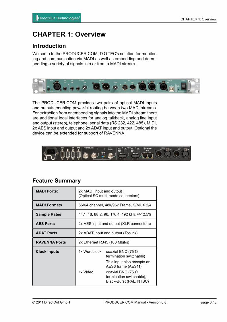
ChAPtER 1: overviewintroductionWelcome to the PRODUCER.COM, D.O.TEC’s solution for monitor-ing and communication via MADI as well as embedding and deem-bedding a variety of signals into or from a MADI stream.
The PRODUCER.COM provides two pairs of optical MADI inputs and outputs enabling powerful routing between two MADI streams. For extraction from or embedding signals into the MADI stream there are additional local interfaces for analog talkback, analog line input and output (stereo), telephone, serial data (RS 232, 422, 485), MIDI, 2x AES input and output and 2x ADAT input and output. Optional the device can be extended for support of RAVENNA.
feature summaryMADi Ports: 2x MADI input and output
(Optical SC multi-mode connectors)
MADi formats 56/64 channel, 48k/96k Frame, S/MUX 2/4
sample Rates 44.1, 48, 88.2, 96, 176.4, 192 kHz +/-12.5%
AEs Ports 2x AES input and output (XLR connectors)
ADAt Ports 2x ADAT input and output (Toslink)
RAvEnnA Ports 2x Ethernet RJ45 (100 Mbit/s)
Clock inputs 1x Wordclock coaxial BNC (75 Ω termination switchable) This input also accepts an AES3 frame (AES11).1x Video coaxial BNC (75 Ω termination switchable), Black-Burst (PAL, NTSC)

CHAPTER 1: OverviewDirectOut Technologies®
© 2011 DirectOut GmbH page 7 / 8PRODUCER.COM Manual - Version 0.8
Clock output 1x Wordclock coaxial BNC
Microphone 1x Mic input XLR connector phantom power switchable
line input 1x stereo, 6.3 mm TRS jack
Auxiliary output 1x stereo, 6.3 mm TRS jack
line output 1x stereo, 2x XLR connectors, trimmable
headphone output 1x stereo, 6.3 mm TRS jack, trimmable
MiDi 1x MIDI input and output, DIN connectors
telephone 2x RJ45 connectors (Ethercon), MFV dial
Remote 1x RJ45 connector (Ethercon) for hardware remote
serial Communication
RS-232 and RS-422 or RS-485
General Purpose 4x GPI (2x optocoupler, 2x voltage input with pull up)4x GPO (2x optocoupler, 2x FET switch, e.g. for red light)
Remote operation USB 2.0 port for remote operation and servicing such as firmware updates.
Power supply This device is equipped with one wide range power supply (84 V to 264 V AC / 47 Hz to 63 Hz / safety class 1).
feature summary (continued)

CHAPTER 1: OverviewDirectOut Technologies®
© 2011 DirectOut GmbH page 8 / 8PRODUCER.COM Manual - Version 0.8
ApplicationsThe PRODUCER.COM can be used to establish a connection of audio signals and for remote operation via a MADI signal. All signals connected to the local interfaces of the device can be transported by two independent MADI streams. Audio signals and control sig-nals (e.g. serial data) are embedded into or deembedded from the MADI signal. Additionally all audio signals can be interconnected offering a wide range of routing possibilities. Signalling events (e.g “red light”) are possible via GPO interfaces and can also be trig-gered by a GPI interface or directly using the remote control.Typical applications include:
• recording session with communication and comfortable moni-toring using a dedicated controller unit.
• communication via telephone, “red light” signalling and remote operation using GPIO and serial data transport over fibre op-tic.
• signal routing between different types of audio interfaces
•

CHAPTER 2: Installation DirectOut Technologies®
© 2011 DirectOut GmbH page 9 / 69PRODUCER.COM Manual - Version 0.8
ChAPtER 2: installation before installing this Device warning Please read and observe ALL of the following notes before installing this product:
• Check the hardware device for transport damage.
• Any devices showing signs of mechanical damage or damage from the spillage of liquids MUST NOT be connected to the mains supply, or disconnected from the mains immediately by pulling out the power lead.
• All devices MUST be grounded. The PRODUCER.COM is grounded through its IEC power connections.
• All devices MUST be connected to the mains using the three-cord power leads supplied with the system. Only supply electrical interfaces with the voltages and signals described in these instructions.
• Do NOT use the device at extreme temperatures. Proper op-eration can only be guaranteed between temperatures of 5º C and 45º C and a maximum relative humidity of 80 %, non-condensing.
Defective Parts/Modules warning This device contains no user-serviceable parts. Therefore do NOT open the device. In the event of a hardware defect, please send the device to your local service representative together with a detailed description of the fault. We would like to remind you to please check carefully whether the failure is caused by erroneous configuration, operation or connec-tion before sending parts for repair. See Chapter X for assistance with troubleshooting.

CHAPTER 2: Installation DirectOut Technologies®
© 2011 DirectOut GmbH page 10 / 69PRODUCER.COM Manual - Version 0.8
first Aid (in case of electric shock) warning
• DO NOT touch the person or his/her clothing before power is turned off, otherwise you risk sustaining an electric shock yourself.
• Separate the person as quickly as possible from the electric power source as follows:
Switch off the equipment.
Unplug or disconnect the mains cable.
• Move the person away from the power source by using dry insulating material (such as wood or plastic).
• If the person is unconscious:
Check their pulse and reanimate if their respiration is poor.
Lay the body down and turn it to one side. Call for a doc-tor immediately.
• Having sustained an electric shock, ALWAYS consult a doc-tor.

CHAPTER 2: Installation DirectOut Technologies®
© 2011 DirectOut GmbH page 11 / 69PRODUCER.COM Manual - Version 0.8
Contents The contents of your PRODUCER.COM package should include:
• 1 x PRODUCER.COM (19’’, 1RU)
• 1 x power chord
• 1 x fixing unit for power plug
• 1 x Manual
updates D.O.TEC products are continually in development, and therefore the information in this manual may be superseded by new releases. To access the latest documentation, please visit the DirectOut website: www.directout.eu.
intended operation The PRODUCER.COM is designed for embedding and deembeding of audio signals and certain types of non-audio signals into and from a MADI signal (AES10). In this context non-audio signals are serial data (RS 232 / 422 / 485), MIDI signals and GPIO triggersignals (low voltage).
warning No compensation can be claimed for damages caused by operation of this unit other than for the intended use described above. Con-secutive damages are also excluded explicitly. The general terms and conditions of business of DirectOut GmbH are applied.

CHAPTER 2: Installation DirectOut Technologies®
© 2011 DirectOut GmbH page 12 / 69PRODUCER.COM Manual - Version 0.8
Conditions of warranty This unit has been designed and examined carefully by the manu-facturer and complies with actual norms and directives. Warranty is granted by DirectOut GmbH over the period of two years for all components that are essential for proper and intended opera-tion of the device. The date of purchase is applied for this period.
warning All claims of warranty will expire once the device has been opened or modified, or if instructions and warnings were ignored. For warranty claims please contact the dealer where your device was acquired.

CHAPTER 2: Installation DirectOut Technologies®
© 2011 DirectOut GmbH page 13 / 69PRODUCER.COM Manual - Version 0.8
Conformity&CertificatesCE This device complies with the basic requests of applicable EU guide-lines. The appropriate procedure for approval has been carried out.
Rohs (Restriction of the use of certain Hazardous Substances) This device was constructed fulfilling the directive on the restriction of the use of certain hazardous substances in electrical and elec-tronic equipment 2002/95/EC.
wEEE (Directive on Waste Electrical and Electronic Equipment) Due to the directive 2002/96/EC for waste disposal this device must be recycled. For correct recycling please dispatch the device to: IMM Elektronik GmbH, Leipziger Strasse 3209648 Mittweida Germany Only stamped parcels will be accepted! WEEE-Reg.-No. DE 93924963
Contact Sales: DirectOut GmbH, Leipziger Strasse 32, 09648 Mittweida, Germany Phone: +49 (0)3727 6205-333 // Fax: +49 (0)3727 6205-56 www.directout.eu
Manufacturer: IMM Elektronik GmbH, Leipziger Strasse 32, 09648 Mittweida, Germany Phone: +49 (0)3727 6205-0 // Fax: +49 (0)3727 6205-56 www.imm-gruppe.de
CHAPTER 2: Installation DirectOut Technologies®
© 2011 DirectOut GmbH page 14 / 69PRODUCER.COM Manual - Version 0.8
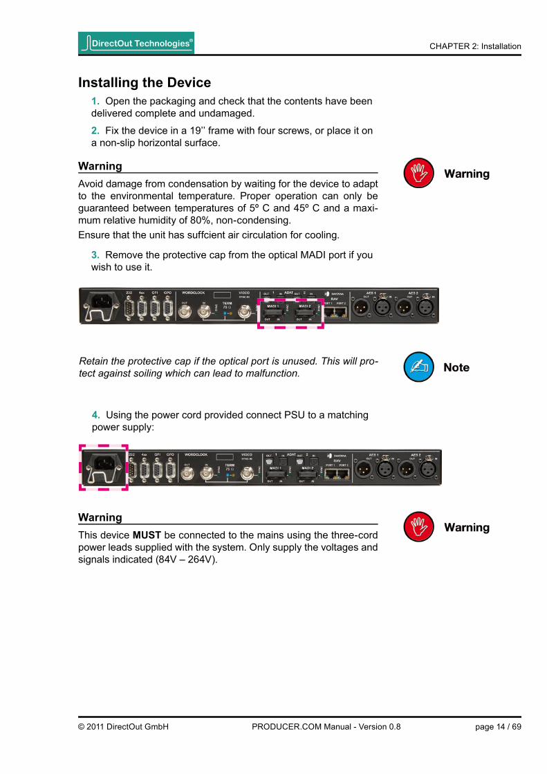
installing the Device 1. Open the packaging and check that the contents have been delivered complete and undamaged.
2. Fix the device in a 19’’ frame with four screws, or place it on a non-slip horizontal surface.
warning Avoid damage from condensation by waiting for the device to adapt to the environmental temperature. Proper operation can only be guaranteed between temperatures of 5º C and 45º C and a maxi-mum relative humidity of 80%, non-condensing. Ensure that the unit has suffcient air circulation for cooling.
3. Remove the protective cap from the optical MADI port if you wish to use it.
warning This device Must be connected to the mains using the three-cord power leads supplied with the system. Only supply the voltages and signals indicated (84V – 264V).
4. Using the power cord provided connect PSU to a matching power supply:
Retain the protective cap if the optical port is unused. This will pro-tect against soiling which can lead to malfunction.

CHAPTER 2: Installation DirectOut Technologies®
© 2011 DirectOut GmbH page 15 / 69PRODUCER.COM Manual - Version 0.8
5. Unpack the PRODUCER.COM REMOTE.
6. Place the device on a non-slip horizontal surface.
7. Connect the PRODUCER.COM REMOTE with the PRODUCER.COM using the delivered RJ45 cable.
Operation of the PRODUCER.COM REMOTE is described in „CHAPTER 6: PRODUCER.COM REMOTE“ on page 43.
For operation via software remote:
7a. Connect PRODUCER.COM to your PC using a standard USB cable.
The use of software remote control requires an installation fi rst. Read „CHAPTER 7: Software Remote“ on page 66 for more de-tails.
8. Turn on the power switch and check the status of PSU on the front panel:
Keep any packaging in order to protect the device should it need to be dispatched for service, warranty, etc.

Chapter 3: OperationDirectOut Technologies®
© 2011 DirectOut GmbH page 16 / 69PRODUCER.COM Manual - Version 0.8
Chapter 3: operationintroduction This chapter describes the basic operation of the device. Note that throughout this manual, the abbreviation FS refers to sample rate or sample frequency. So, when dealing with scaling factors, the follow-ing sample rates can be written as:
• 44.1kHz = 1FS; 88.2kHz = 2FS; 176.4kHz = 4FS or
• 48kHz = 1FS; 96kHz = 2FS; 192kHz = 4FS
Global ControlThe control on the right of the front panel indicates the power supply and sync status:
Power Switch to enable / disable power supply.
on ( sync) LED OFF = Power supply inactiveLED ON = Power supply active, device is syncedLED fl ashing = Device is not lockedLED fl ickering = Talkback is active
The green LED (ON, Sync) indicates that a working power supply is connected to the power supply unit. Note that an unlit LED does not guarantee that the device is free of voltage. Always unplug the power chord to ensure the power supply is disconnected.

Chapter 3: OperationDirectOut Technologies®
© 2011 DirectOut GmbH page 17 / 69PRODUCER.COM Manual - Version 0.8
Remote operationUp to two PRODUCER.COMs can be controlled using:
• PRODUCER.COM REMOTEand / or
• Software Remote (on a Windows PC)
Both the PRODUCER.COM REMOTE and the Software Remote provide access to all functions and can be used in parallel. So when dealing with remote operation the term “REMOTE” is used through-out this manual.
The use of software remote control requires an installation fi rst. Read chapter „CHAPTER 7: Software Remote“ on page 66 for more details.
PC usb socketUSB connection for software remote control. Requires a standard USB cable (Type B).
box RJ45 socketConnection for PRODUCER.COM RemoteRequires a standard CAT5 cable for con-nection of the proprietary signal and protocol.A second remote box (satellite box) can be connected at the second port of the PRODUCER.COM REMOTE.
All settings are stored within the device. So after a loss of power the last confi guration is preserved.
Control of two PRODUCER.COMs (“local” and “remote”) is possible by switching between “local” and “remote” in the REMOTE interface. The control data to the “remote” device is tunnelled in the MADI sig-nal (Port: MADI Com).
Use presets in the software remote to store / restore complex sce-narios.

Chapter 3: OperationDirectOut Technologies®
© 2011 DirectOut GmbH page 18 / 69PRODUCER.COM Manual - Version 0.8
MonitoringThree different analog output ports for monitoring are provided. Each port may output its own signal. The signal routing for each port is done in the REMOTE.
linE out 2x xlR socket (male) - balancedAnalog line signal output for use with external amplifi er or active monitors.Volume level is controlled by REMOTE and can be trimmed locally.Output signal can be assigned arbitrary by routing matrix.
PhonEs tRs Jack (6.3 mm, stereo)Stereo signal output for headphones.Volume level is controlled by REMOTE and can be trimmed locally.Output signal is hardwired with the internal bus PHONES.
Aux out tRs Jack (6.3 mm, stereo) - unbalancedAnalog line signal output for use with external amplifi er or active monitors.Volume level is controlled by REMOTE only.Output signal is hardwired with the internal bus AUX.
Use the monitor busses (MAIN MONITOR A/B, PHONES A/B and AUX) with dsp functions (DIM, MUTE, DUCK) for convenient moni-toring.
Range of Trim: ∞ to + 18 dB (“midnight” = unity)

Chapter 3: OperationDirectOut Technologies®
© 2011 DirectOut GmbH page 19 / 69PRODUCER.COM Manual - Version 0.8
MiC in xlR socket (female) - balancedMicrophone input, connect a microphone here.
P48 switchEnables / disables phantom power (48 volts) for MIC IN Mic gain (ON): + 20 dBMic gain (OFF): + 30 dBDigital gain from -38 dB to +40 dB can be applied (Level setting of 20 equals to unity.).
P48 lED lED (yellow): indicates the status of the phantom power source,LED OFF = phantom power inactiveLED ON = phantom power active
linE in tRs Jack (6.3 mm, stereo) - unbalancedLine input, connect a line signal source here.Digital gain from -38 dB to +40 dB can be applied (Level setting of 20 equals to unity.).
tEl 1 RJ45 socketAnalog telephone port, connect Tel 1 here.
tEl 2 RJ45 socketAnalog telephone port, connect Tel 2 here.
The telephone interface can detect DTFM signal for incoming calls. However once the phone is picked up the connection is established without the need of calling fi rst.
Each telephone signal is transported transparently in an AES chan-nel pair, thus allowing to output the signal directly to any sink or to receive any source at the telephone.
CommunicationTwo analog inputs may be used e.g. for talkback and listen applica-tions. Two telephone interfaces with DTMF detection can be used for communication between two PRODUCER.COMs.

Chapter 3: OperationDirectOut Technologies®
© 2011 DirectOut GmbH page 20 / 69PRODUCER.COM Manual - Version 0.8
AEs 1 in xlR socket (female)AES3 input (2 ch), connect AES 1 input here.
AEs 1 out xlR socket (male)AES3 output (2 ch), connect AES 1 output here.
AEs 2 in xlR socket (female)AES3 input (2 ch), connect AES 2 input here.
AEs 2 out xlR socket (male)AES3 output (2 ch), connect AES 2 output here.
ADAt 1 in toslink socket (optical)ADAT input (8 ch), connect ADAT 1 input here.
ADAt 1 out toslink socket (optical)ADAT output (8 ch), connect ADAT 1 output here.
ADAt 2 in toslink socket (optical)ADAT input (8 ch), connect ADAT 2 input here.
ADAt 2 out toslink socket (optical)ADAT output (8 ch), connect ADAT 2 output here.
Digital Audio signalsA variety of different digital audio interfaces are provided for multi purpose applications. All signal ports can be connected to each oth-er on single channel level.

Chapter 3: OperationDirectOut Technologies®
© 2011 DirectOut GmbH page 21 / 69PRODUCER.COM Manual - Version 0.8
MADi 1 in sC socket (optical)MADI input (64 ch), connect MADI 1 input here (MADI Local).
MADi 1 out sC socket (optical)MADI output (64 ch), connect MADI 1 output here (MADI Local).
MADi 1 - lED sync lED (green): indicates sync status of incoming MADi signalLED ON = signal lockedLED OFF = no signal presentLED fl ashing = signal present, not locked
MADi 2 in sC socket (optical)MADI input (64 ch), connect MADI 2 input here (MADI Com).
MADi 2 out sC socket (optical)MADI output (64 ch), connect MADI 2 output here (MADI Com).
MADi 2 - lED sync lED (green): indicates sync status of incoming MADi signalLED ON = signal lockedLED OFF = no signal presentLED fl ashing = signal present, not locked
RAvEnnA Port 1(optional)
RJ45 socket (Ethernet)Connect audio over ip network here.
RAvEnnA Port 2(optional)
RJ45 socket (Ethernet)Connect audio over ip network here.
MADI 1 equals “MADI Local” and MADI 2 equals “MADI Com”.
The remote control signal for the second PRODUCER.COM and the calling trigger signals for telephone are transported in the MADI Com stream (MADI 2).
Digital Audio signals - continued

Chapter 3: OperationDirectOut Technologies®
© 2011 DirectOut GmbH page 22 / 69PRODUCER.COM Manual - Version 0.8
ClockingThe PRODUCER.COM can be clocked internally or by wordclock or video or by one of the digital audio inputs. The system clock is output at the wordclock output additionally.
woRDCloCK out bnC socket (coaxial),connect wordclock output signal here.
woRDCloCK in bnC socket (coaxial),connect wordclock or AES3 DARS (Digital Audio Reference Signal) here.
woRDCloCK - sYnC
lED (green): indicates the sync status of the incoming wordclock signalLED ON = signal lockedLED OFF = no signal presentLED fl ashing = signal present, not locked
TERM75Ω switchSelects 75 Ω termination for wordclock and video input.To ensure proper operation of the device, an appropriate termination status must be selected
TERM75Ω-LED lED (yellow): indicates the termination status of wordclock and video input.LED ON = termination enabledLED OFF = termination disabled
viDEo sYnC-in bnC socket (coaxial),connect video reference signal here(Black burst PAL or NTSC; the Video standard is detected automatically).
viDEo sYnC-in - sYnC
lED (green): indicates the sync status of the incoming video signalLED ON = signal lockedLED OFF = no signal presentLED fl ashing = signal present, not locked
Note that the output base rate (44.1k or 48k) is defi ned automatically by the wordclock or digital audio input signal if the clock source is set to wordclock or the corresponding digital audio input respectively.

Chapter 3: OperationDirectOut Technologies®
© 2011 DirectOut GmbH page 23 / 69PRODUCER.COM Manual - Version 0.8
user DataFor remote application and signalling purposes there are connec-tion possibilities for RS 232 / 422 / 485, DMX, MIDI and General Purpose Input Output (GPIO).Serial signals can be routed either by using userbits of a MADI frame or by using a whole audio channel. The last may serve as a workaround for setups where the userbits are not being processed transparently by other devices in the chain.4 GPOs can be triggered by 4 GPIs or push buttons at the REMOTE or footswitch (PC REMOTE only).See also „CHAPTER 5: GPIO / Serial Interfaces“ on page 38 for detailed information about the use of GPIO.
MiDi in Din socketconnect MIDI input signal here.
MiDi out Din socketconnect MIDI output signal here.
All data is embedded into the MADI Com stream and taken from there. To pass through already embedded data from MADI Lo-cal to MADI Com set Tunnel to ‘off’ for the respective serial port (see „Routing - User Data“ on page 36).

Chapter 3: OperationDirectOut Technologies®
© 2011 DirectOut GmbH page 24 / 69PRODUCER.COM Manual - Version 0.8
user Data - continued
Rs 232 D9 sub socket (male)Connect RS 232 signal here.Observe the correct pin assignment.For safe operation lock the connection using the jack bolts.
Rs 4xx D9 sub socket (female)Connect RS 422 or RS 485 or DMX signal here.Observe the correct pin assignment.For safe operation lock the connection using the jack bolts.
GPi D9 sub socket (female) - General Purpose inputConnect GPI signals here.Observe the correct pin assignment.For safe operation lock the connection using the jack bolts.
GPo D9 sub socket (female) - General Purpose outputConnect GPO signals here.Observe the correct pin assignment.For safe operation lock the connection using the jack bolts.
Consult the instructions in „CHAPTER 5: GPIO / Serial Interfaces“ on page 38 for correct pin assignment of the D9 sub connectors.
All data is embedded into the MADI Com stream and taken from there. To pass through already embedded data from MADI Local to MADI Com set Tunnel to ‘off’ for the respective serial port (see also „Routing - User Data“ on page 36).

CHAPTER 4: ROUTINGDirectOut Technologies®
© 2011 DirectOut GmbH page 25 / 69PRODUCER.COM Manual - Version 0.8
ChAPtER 4: RoutinGThe PRODUCER.COM provides extensive routing capabilities be-tween the various interfaces. Audio signals can be routed from and to each audio interface.
Routing - terms
term Explanation Members
inPut Hardware input for analog and digital audio signals.
MIC IN LINE IN TEL IN AES IN ADAT IN RAVENNA IN MADI IN
outPut Hardware output for analog and digital audio signals. Gets signal from <INPUT> or <BUS> or <VIRTUAL CHANNEL>.
LINE OUT AUX OUT PHONES TEL OUT AES OUT ADAT OUT RAVENNA OUT MADI OUT
bus Internal bus, gets signal from <INPUT> and is fed to <OUTPUT>, DSP operations (DIM, MUTE, DUCK) can be applied to.
MAIN MONITOR (A/B) PHONES (A/B) AUX
viRtuAl ChAnnEl
Internal channel, gets signal from <INPUT> and is fed or added to <OUTPUT> if activated. May trigger DSP function on <BUS>. Mono channel, fed to both channels, when routed to a pair.
TALKBACK LISTEN

CHAPTER 4: ROUTINGDirectOut Technologies®
© 2011 DirectOut GmbH page 26 / 69PRODUCER.COM Manual - Version 0.8
Busses
Outputs
Inputs
Main Monitor (A/B) Phones (A/B)Aux
Mic InLine InTel InAES InADAT InRAVENNA InMADI In
Line OutPhones OutAux OutTel OutAES OutADAT OutRAVENNA OutMADI Out
ListenTel 1Tel 2
DSP
DIMMUTETalkbackListenCall 1 / Call 2Red / WhiteGPI
Routing - sketchIn general each node is seen from the output; i.e. the input source is assigned to a selected output. Internal busses are used for dsp operations (dim, duck and mute) to provide comfortable monitor-ing. Virtual channels help with communication applications. User data can be embedded in the MADI Com signal using whole audio channels or userbits to control remote devices or to trigger events (GPIO).

CHAPTER 4: ROUTING
MADI local no route1 - 64
AES 1 - 4
RAVENNA 1 - 8
Mic In 1 - 40
Line In 1 - 40
1 - 2
Tel 1
Tel 2
1:1
Main Monitor
Talkback
Listen
Parameter Subparameter Value Subvalue Explanation
no signal to MADI local (1-64)
AES (1-4) to MADI local (1-64)
RAVENNA (1-8) to MADI local (1-64)
Mic In (gain setting) to MADI local (1-64)
Line In (gain setting) to MADI local (1-64)
Main Monitor (1-2) to MADI local (1-64), with DSP operation
Talkback to MADI local (1-64), with DSP operation
Listen to MADI local (1-64), with DSP operation
Telephone 1 Output to MADI local (1-64)
Telephone 2 Output to MADI local (1-64)
sets routing to corresponding portMADI com (1-64) In to MADI local (1-64) Out
Serial Serial signal to MADI local (1-64)
MADI com 1 - 64 MADI com (1-64) to MADI local (1-64)
ADAT 1 - 16 ADAT (1-16) to MADI local (1-64)
MADI local 1 - 64 MADI local (1-64) to MADI local (1-64)ADAT 1 = 1 - 8ADAT 2 = 9 - 16
AES 1 = 1 - 2AES 2 = 3 - 4
DirectOut Technologies®
© 2011 DirectOut GmbH page 27 / 69PRODUCER.COM Manual - Version 0.8
Routing - inputs and outputsThe patching for each output sink can be selected individually at channel level; i.e. it is e.g. possible to route single channels from a MADI port to a single channel of an ADAT port. Also multiple assign-ment of the same input source to many output sinks is possible; thus offering signal distribution. Digital signals are processed bittranspar-ent as long as no embedding of user data is used (See „Routing - User Data“ on page 36).All routing can be selected similarly in both the PRODUCER.COM REMOTE and in the software remote.
Use presets in the software remote to store / restore complex sce-narios.
Below an example for an output routing page. The menu for signal routing is explained completely in „CHAPTER 6: PRODUCER.COM REMOTE - „Menu - Audio Routing“ on page 51.

CHAPTER 4: ROUTING
Routing - bussesThree monitoring busses (MAIN MONITOR, PHONES, AUX) can be controlled by the REMOTE. They are fed by an arbitrary input source and - on their part acting as source - they can be routed to any output sink.Combined with the telephone functions (see „Calling - extended“ on page 35) a rich set of individual monitoring setups are possible.Dedicated encoder on the REMOTE set the monitor level of each bus separately. In general the dsp functions DIM and MUTE are triggered by push buttons or by a GPI event (see „GPI“ on page 38). Each bus may be confi gured individually regarding the dsp functions.
Each bus acts as a stereo output sink that is routed as stereo pair (odd = left channel, even = right channel). The channel pair is patched irrespective the selection of the odd or even number of the channel pair.
DirectOut Technologies®
© 2011 DirectOut GmbH page 28 / 69PRODUCER.COM Manual - Version 0.8

CHAPTER 4: ROUTING
MAin MonitoRAlternative routing (A/B) is switchable for comparison between dif-ferent sources. Level control is set by the encoder “MAIN VOL” on the REMOTE.Five settings defi ne the behaviour of the dsp functions:
• DIM: enables attenuation and defi nes its level once “DIM” is active.
• TALK: enables attenuation and defi nes its level once “TALK” is active.
• LISTEN: enables attenuation and defi nes its level once “LIS-TEN to BUS” is active. If enabled the signal of the “listen chan-nel” is added to the bus.
• CALL 1: enables attenuation and defi nes its level once “CALL 1 to BUS” is active. If enabled the incoming signal of “Tel 1” is added to the bus (see „Calling - extended“ on page 35).
• CALL 2: enables attenuation and defi nes its level once “CALL 2 to BUS” is active. If enabled the incoming signal of “Tel 2” is added to the bus (see „Calling - extended“ on page 35).
Main Monitor no RouteA
B
Volume
Dim
Talk
Listen
Call 1
Call 2
ADAT 1 - 16
RAVENNA 1 - 8
Mic In 1 - 40
Line In 1 - 40
Parameter Subparameter Value Subvalue Explanation
no signal to Main Monitor
MADI com 1 - 64 MADI com (1-64) to Main Monitor
ADAT (1-16) to Main Monitor
RAVENNA (1-8) to Main Monitor
Mic In (gain setting) to Main Monitor
Line In (gain setting) to Main Monitor
MADI local 1 - 64 MADI local (1-64) to Main Monitor
-- 1 - 64 Sets Volume level
Attenuation 1 - 64, MuteSets attenuation level for DIMON = enable DIM
On, O� 1 - 64, Mute Sets attenuation level (DIM) for TALK, ON = enable DIM
On, O� 1 - 64, Mute Sets attenuation level (DUCK) for LISTEN,ON = LISTEN is added to bus
On, O� 1 - 64, Mute Sets attenuation level (DUCK) for CALL 1,ON = Call to bus (Tel 1 is added to bus)
Sets attenuation level (DUCK) for CALL 2,ON = Call to bus (Tel 2 is added to bus)On, O� 1 - 64, Mute
AES 1 - 4 AES (1-4) to Main Monitor
same as for Main Monitor <A>
Signal RoutingD
SP Processing
Stereo bus; i.e. selection of one channel involves patching of the correspon-ding channel.E.g. MADI local 11 to Main Monitor A => MADI local 11 and 12 are patched.
ADAT 1 = 1 - 8ADAT 2 = 9 - 16
AES 1 = 1 - 2AES 2 = 3 - 4
DirectOut Technologies®
© 2011 DirectOut GmbH page 29 / 69PRODUCER.COM Manual - Version 0.8

CHAPTER 4: ROUTING
PhonEsAlternative routing (A/B) is switchable for comparison between dif-ferent sources. Level control is set by the encoder “PHONES” on the REMOTE and can be trimmed locally. This bus is output at the “PHONES” jack only.Five settings defi ne the behaviour of the dsp functions:
• DIM: enables attenuation and defi nes its level once “DIM” is active.
• TALK: enables attenuation and defi nes its level once “TALK” is active.
• LISTEN: enables attenuation and defi nes its level once “LIS-TEN to BUS” is active. If enabled the signal of the “listen chan-nel” is added to the bus.
• CALL 1: enables attenuation and defi nes its level once “CALL 1 to BUS” is active. If enabled the incoming signal of “Tel 1” is added to the bus (see „Calling - extended“ on page 35).
• CALL 2: enables attenuation and defi nes its level once “CALL 2 to BUS” is active. If enabled the incoming signal of “Tel 2” is added to the bus (see „Calling - extended“ on page 35).
Phones no RouteA
B
Volume
Dim
Talk
Listen
Call 1
Call 2
ADAT 1 - 16
RAVENNA 1 - 8
Mic In 1 - 40
Line In 1 - 40
Parameter Subparameter Value Subvalue Explanation
no signal to Phones
MADI com 1 - 64 MADI com (1-64) to Phones
ADAT (1-16) to Phones
RAVENNA (1-8) to Phones
Mic In (gain setting) to Phones
Line In (gain setting) to Phones
MADI local 1 - 64 MADI local (1-64) to Phones
-- 1 - 64 Sets Volume level
Attenuation 1 - 64, Mute
On, O� 1 - 64, Mute
On, O� 1 - 64, Mute
On, O� 1 - 64, Mute
On, O� 1 - 64, Mute
AES 1 - 4 AES (1-4) to Phones
same as for Phones <A>
Signal RoutingD
SP Processing
Sets attenuation level (DIM) for TALK, ON = enable DIM
Sets attenuation level (DUCK) for LISTEN,ON = LISTEN is added to bus
Sets attenuation level (DUCK) for CALL 1,ON = Call to bus (Tel 1 is added to bus)
Sets attenuation level (DUCK) for CALL 2,ON = Call to bus (Tel 2 is added to bus)
Sets attenuation level for DIMON = enable DIM
ADAT 1 = 1 - 8ADAT 2 = 9 - 16
AES 1 = 1 - 2AES 2 = 3 - 4
DirectOut Technologies®
© 2011 DirectOut GmbH page 30 / 69PRODUCER.COM Manual - Version 0.8
CHAPTER 4: ROUTING
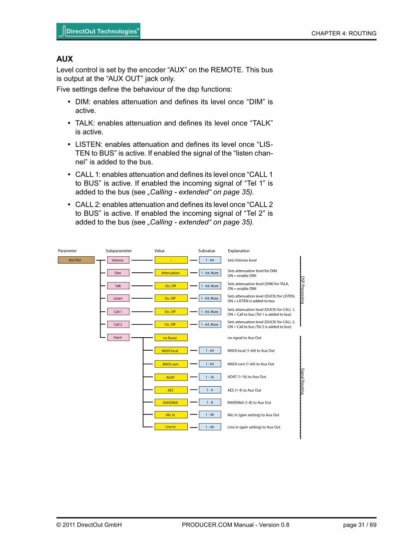
AuxLevel control is set by the encoder “AUX” on the REMOTE. This bus is output at the “AUX OUT” jack only.Five settings defi ne the behaviour of the dsp functions:
• DIM: enables attenuation and defi nes its level once “DIM” is active.
• TALK: enables attenuation and defi nes its level once “TALK” is active.
• LISTEN: enables attenuation and defi nes its level once “LIS-TEN to BUS” is active. If enabled the signal of the “listen chan-nel” is added to the bus.
• CALL 1: enables attenuation and defi nes its level once “CALL 1 to BUS” is active. If enabled the incoming signal of “Tel 1” is added to the bus (see „Calling - extended“ on page 35).
• CALL 2: enables attenuation and defi nes its level once “CALL 2 to BUS” is active. If enabled the incoming signal of “Tel 2” is added to the bus (see „Calling - extended“ on page 35).
Aux Out
Parameter Subparameter Value Subvalue Explanation
Volume
Input
Dim
Talk
Listen
Call 1
Call 2
-- 1 - 64 Sets Volume level
Attenuation 1 - 64, Mute
On, O� 1 - 64, Mute
On, O� 1 - 64, Mute
On, O� 1 - 64, Mute
On, O� 1 - 64, Mute
no Route
ADAT 1 - 16
RAVENNA 1 - 8
Mic In 1 - 40
Line In 1 - 40
no signal to Aux Out
MADI com 1 - 64 MADI com (1-64) to Aux Out
ADAT (1-16) to Aux Out
RAVENNA (1-8) to Aux Out
Mic In (gain setting) to Aux Out
Line In (gain setting) to Aux Out
MADI local 1 - 64 MADI local (1-64) to Aux Out
AES 1 - 4 AES (1-4) to Aux Out
Signal RoutingD
SP Processing
Sets attenuation level (DIM) for TALK, ON = enable DIM
Sets attenuation level (DUCK) for LISTEN,ON = LISTEN is added to bus
Sets attenuation level (DUCK) for CALL 1,ON = Call to bus (Tel 1 is added to bus)
Sets attenuation level (DUCK) for CALL 2,ON = Call to bus (Tel 2 is added to bus)
Sets attenuation level for DIMON = enable DIM
DirectOut Technologies®
© 2011 DirectOut GmbH page 31 / 69PRODUCER.COM Manual - Version 0.8

CHAPTER 4: ROUTING
Routing - virtual channelsTwo mono virtual channels (TALKBACK and LISTEN) are used in-ternally. They are fed by an arbitrary input source and - on their part acting as source - they can be routed to any output sink. The signal output is switchable by dedicated push buttons or footswitch. Their use may trigger dsp operations (DIM, DUCK, MUTE, CALL to BUS and LISTEN to BUS) to the busses and the telephone channels (TALKBACK).
tAlKbACK - how it could be usedThe TALKBACK channel (mono) is fed by any input source. It is switched by the push button TALK on the REMOTE or by footswitch (jack at the rear of PRODUCER.COM REMOTE).Switching behaviour:
• Press short to toggle between TALKBACK ON and OFF.
• Press and hold to activate TALBACK - release to deactivate.
Example:Talkback source: MIC IN (local)Destinations: MADI 1 - 63 (“recording”) and MADI 2 - 63 (“to stage”)Once TALK is active the microphone signal may be recorded on track 63 for logging purpose and sent to a monitor mixing desk for communication or a second PRODUCER.COM on stage that can output the talkback signal on a monitor bus.Depending of the setting the monitor bus is dimmed e.g. to prevent feedback.
The routed signal source of the TALKBACK channel is also sent to TEL 1 resp. TEL 2 once CALL 1 resp CALL 2 is active.
The LED Sync at the front panel will fl icker if TALBACK is active.
Both virtual channels are mono. When routed to a stereo output sink the signal is sent to both channels of the channel pair - dual mono. The channel pair is patched irrespective the selection of the odd or even number of the channel pair.
DirectOut Technologies®
© 2011 DirectOut GmbH page 32 / 69PRODUCER.COM Manual - Version 0.8

CHAPTER 4: ROUTING
listEn - how it could be usedThe LISTEN channel (mono) is fed by any input source. It is switched by the push button LISTEN on the REMOTE or by footswitch (jack at the rear of PRODUCER.COM REMOTE).Switching behaviour:
• Press short to toggle between LISTEN ON and OFF.
• Press and hold to activate LISTEN - release to deactivate.
Example:Listen source: MADI 2 - 64 (“spy microphone on stage”)Destination: MADI 2 - 64 (“recording”)Once LISTEN is active the signal from MADI 2 - 64 is recorded on track 64 for logging purpose.Additionally if “LISTEN to BUS” is activated in the bus setup duck-ing of the monitor signal is applied and the signal of the channel is added to the corresponding bus.
DirectOut Technologies®
© 2011 DirectOut GmbH page 33 / 69PRODUCER.COM Manual - Version 0.8

CHAPTER 4: ROUTING
Pin Signal1234 a5 b678
DirectOut Technologies®
© 2011 DirectOut GmbH page 34 / 69PRODUCER.COM Manual - Version 0.8
Routing - telephoneThe following part refers to the use of “TEL 1” only. Respectively the use of “TEL 2” is identical.
Calling - basicTwo PRODUCER.COMs (PC local and PC remote) each of with a telephone connected at “TEL 1”. Both PRODUCER.COMs are bi-directional connected via the MADI Com port (MADI 2).Routing (example): PC local: TEL 1 gets MADI 2 - 64PC remote: TEL 1 gets MADI 2 - 64The microphone signal of the phone is transmitted in audio channel MADI 2 - 64. Once the phone is off-hook each phone receiver gets signal from input source that is routed to “TEL 1”; i.e. MADI 2- 64.Calling is made using:
• Push button CALL 1
• Dialing “1” using the numeric key pad of the phone.
wiring - RJ 45 jack (tEl 1 / tEl 2)
Calling trigger signals are transmitted in the MADI Com stream (MADI 2) only.
12345678

CHAPTER 4: ROUTINGDirectOut Technologies®
© 2011 DirectOut GmbH page 35 / 69PRODUCER.COM Manual - Version 0.8
RJ45
Mic @ TEL 1Ear @ TEL 1
<Output Sink>
„TEL 1“
<Signal Source> of TALKBACK
„TEL 1“
<Signal Source>
Monitor Bus
<Output Sink>
CALL 1 to BUS
CALL 1CALL 1
+
Calling - extendedFor conversation using the monitor bus(ses) and the TALKBACK channel an extended signal routing can be applied.
• “CALL 1 to BUS” will duck the monitor signal and add the “ear signal” to the bus once CALL 1 is active.
• <signal source> of the TALKBACK channel is added to the “mic signal”. The summed signal is sent to all output ports that have “TEL 1” routed as signal source.
So a telephone conversation could be done e.g. using the PHONES for listening and using the local microphone for talking (TALKBACK source = MIC IN).CALL to BUS can be applied for each bus (MAIN MONITOR, PHONES, AUX) separately.

CHAPTER 4: ROUTINGDirectOut Technologies®
© 2011 DirectOut GmbH page 36 / 69PRODUCER.COM Manual - Version 0.8
Routing - user DataUser data are serial signals (RS 232, 422, 485 and DMX) and MIDI signals. In general all signals are processed bittransparent preserving user data that is already embedded in the signal.Local ports offer the possibility to embed user data into or to extract user data from a MADI stream.To transmit user data via the local ports a tunnel has to be setup fi rst:
a) Embedding: Specify the tunnel where the user data is to be embedded.
b) Deembedding: Specify the tunnel from where the user data is to be extracted.
For bidirectional use of the local ports the tunnel settings of both PRODUCER.COMs must match.
Serial signals are transmitted either by using userbits of a MADI frame or by using a whole audio channel. The last may serve as a workaround for setups where the userbits are not being processed transparently by other devices in the chain.MIDI signals from the local MIDI ports can be tunnelled either by MADI local or MADI com.It is not possible to tunnel more than one serial signal in a userbit tunnel. So e.g. if RS 232 reserves <Userbit 1> the RS 422 signal has to use either <Userbit 2> or an audio channel. If both RS ports are set to the same userbit the RS 232 port has priority.
how to setup Rs xxx tunnel?• Connect the serial signal to the D9 Sub port at the rear panel
• Select Parameter <RS xxx> and goto Subparameter <Tunnel>
• Defi ne <U-Bit> (subvalue 1 or 2) for transmission via userbit
• Defi ne <MADI Com> (subvalue channel 1-64) for transmis-sion via audio channel. This requires an output patch of the selected channel to <serial> (Parameter: MADI Com, Value: Serial).
how to setup a MiDi tunnel?• Connect the MIDI signal to the local MIDI ports at the front
panel
• Select Parameter <MIDI>
• Defi ne value <local> resp. <remote> for tunneling in MADI lo-cal resp. MADI com signal
See „Menu - User data“ on page 62.
CHAPTER 4: ROUTING
RS 232 RS 4xx MIDIIN OUT
Embedder / DeembedderUserbit 1O�
Userbit 2Audio (com)
Embedder / DeembedderUserbit 1O�
Userbit 2Audio (com)
Embedder / Deembedder
O�
MADI com
MADI local
MIDIIN OUT
RS 4xxRS 232
Embedder / DeembedderUserbit 1O�
Userbit 2Audio (com)
Embedder / DeembedderUserbit 1O�
Userbit 2Audio (com)
Embedder / Deembedder
O�
MADI com
MADI local
MADI Local
MADI Com
PRO
DU
CER.
COM
#1
PRO
DU
CER.
COM
#2
DirectOut Technologies®
© 2011 DirectOut GmbH page 37 / 69PRODUCER.COM Manual - Version 0.8
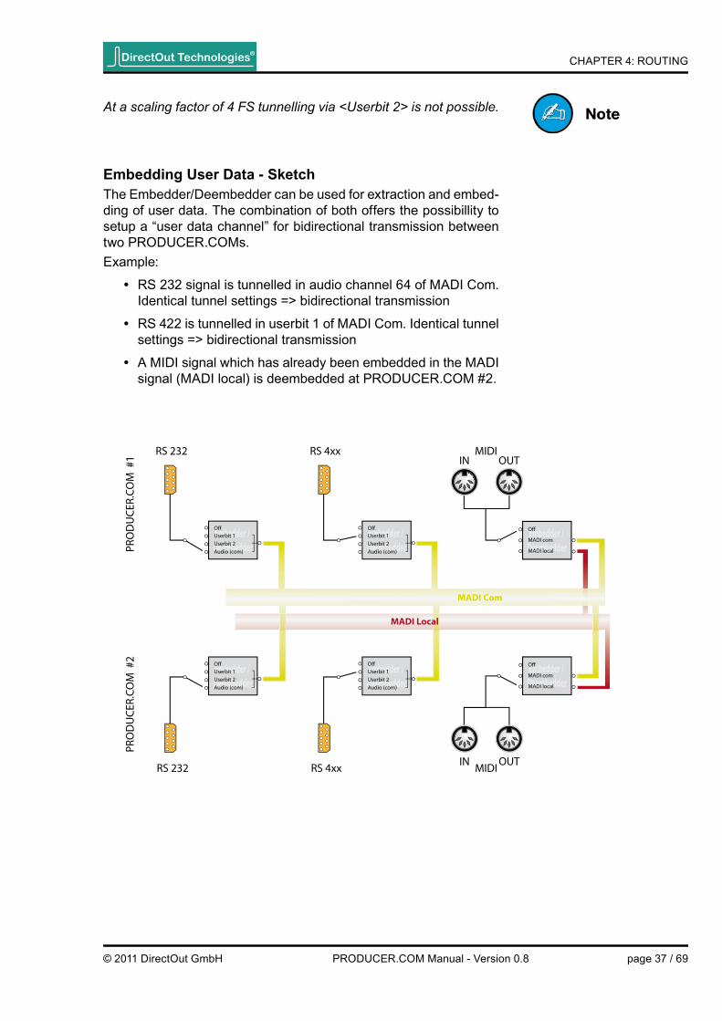
Embedding user Data - sketchThe Embedder/Deembedder can be used for extraction and embed-ding of user data. The combination of both offers the possibillity to setup a “user data channel” for bidirectional transmission between two PRODUCER.COMs.Example:
• RS 232 signal is tunnelled in audio channel 64 of MADI Com. Identical tunnel settings => bidirectional transmission
• RS 422 is tunnelled in userbit 1 of MADI Com. Identical tunnel settings => bidirectional transmission
• A MIDI signal which has already been embedded in the MADI signal (MADI local) is deembedded at PRODUCER.COM #2.
At a scaling factor of 4 FS tunnelling via <Userbit 2> is not possible.

CHAPTER 5: GPIO / Serial Interfaces
ChAPtER 5: GPio / serial interfacesGPiA GPI is used to trigger an event or to toggle a switch by changing the status of a logic; i.e. from 0 to 1 or vice versa.
PRODUCER.COM provides four GPIs using two different methods (two each) for triggering:
Method 1: optocouplerControl voltage (5V) between the input pins causes the emitter of the optocoupler to change its level from low (0) to high (1).Pins: 1/6 & 2/7
Method 2: voltage input with Pull-upIdle state of the input is high (1). By connecting the input pin to GND, the level will change to low (0).Alternatively this input can be driven by a voltage source, of which the high (1) level can be as high as 30 V due to a safety limiter in the input.Pins: 4/8 & 5/9
Method 1 avoids an electrical connection between input signal and the device reducing the risk of grounding issues.Method 2 doesn't need more than a switch, but it can also accept voltage sources like TTL or CMOS outputs.
The following terms are used in the menu of the REMOTE:
• Optocoupler: Opto 1, Opto 2
• Voltage Input: Volt 1, Volt 2
DirectOut Technologies®
© 2011 DirectOut GmbH page 38 / 69PRODUCER.COM Manual - Version 0.8
CHAPTER 5: GPIO / Serial Interfaces
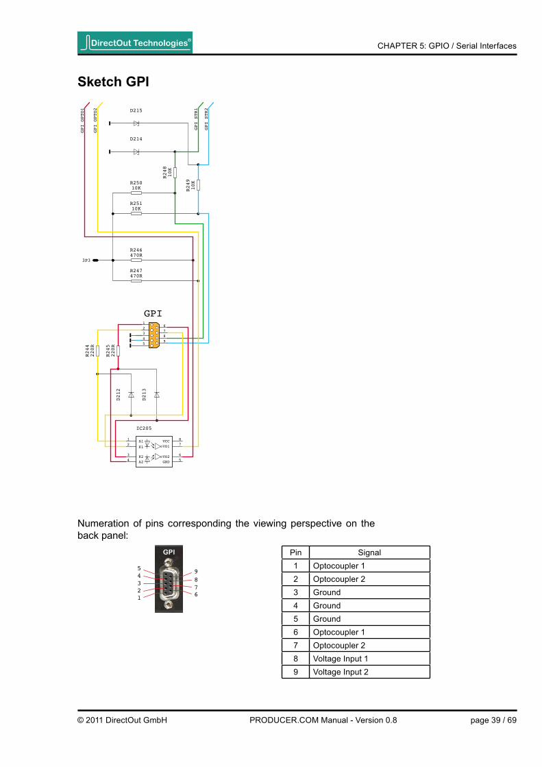
sketch GPi
Numeration of pins corresponding the viewing perspective on the back panel:
GPI
VCC
GNDVO2
VO1A1
K1
K2A2
D212
D213
D214
D215
IC205
R244
220R
R245
220R
R248
10K
R249
10K
GPI_OPTO1
GPI_OPTO2
12
34 5
6
78
R246470R
R247470R
R25010K
R25110K
3P3
GPI_STR2
GPI_STR1
16
27
38
49
5
5 94
837261
Pin Signal1 Optocoupler 12 Optocoupler 23 Ground4 Ground5 Ground6 Optocoupler 17 Optocoupler 28 Voltage Input 19 Voltage Input 2
DirectOut Technologies®
© 2011 DirectOut GmbH page 39 / 69PRODUCER.COM Manual - Version 0.8

CHAPTER 5: GPIO / Serial Interfaces
GPoA GPO provides the consequence of a triggered event (used by the GPI).
The PRODUCER.COM provides four GPOs using two different methods (two each):
Method 1: solid state RelayTwo pins are connected to a switch, which is opened or closed by the control signal. The output is potential-free like a relay. It can handle a switching voltage up to 60 V and a current up to 600 mA.Method 1 avoids an electrical connection between switch and de-vice thus reducing the risk of grounding issues.Pins: 1/6 & 2/7
Method 2: fEt switch The control signal enables or disables a low resistance switch to GND. It can handle an external voltage between 0 V and 12 V.Pins: 8 & 9
In addition to the four GPO outputs, the ProducerCom provides a voltage source of 12 V for signalling purposes (Pins: 4 & 5). This output is current-limited to 200 mA and it can be used e. g. for signal lights together with the SSRs and FET switches.
The following terms are used in the menu of the REMOTE:
• Solid State Relay: Relais 1, Relais 2
• FET Switch: Volt 1, Volt 2
DirectOut Technologies®
© 2011 DirectOut GmbH page 40 / 69PRODUCER.COM Manual - Version 0.8

CHAPTER 5: GPIO / Serial Interfaces
sketch GPo
weiss
rot
weiss
rot
GPO
D203
D206
D205
R220 R221
R222
1K
R227
1K
REL202
K
A
NC
REL203
K
A
NC
12V_200MA
WEISS-RELAIS
ROT-RELAIS
ROT-FET
WEISS-FET
1
2
3 4
5
6 1
2
3 4
5
6
T212
D204
T207
16
27
38
49
5
Numeration of pins corresponding the viewing perspective on the back panel:
1 62
738495
Pin Signal1 Optocoupler 12 Optocoupler 23 Ground4 + 12V (max. 200 mA)5 + 12V (max. 200 mA)6 Optocoupler 17 Optocoupler 28 FET switch 19 FET switch 2
DirectOut Technologies®
© 2011 DirectOut GmbH page 41 / 69PRODUCER.COM Manual - Version 0.8

CHAPTER 5: GPIO / Serial Interfaces
sketch serial interfacessketch Rs 232
RS485_RS422_TX-
RS485_RS422_TX+
RS422_RX-
RS422_RX+
RS232_TXRS232_RX
16
27
38
49
5
16
27
38
49
5
RS485_RS422_TX-
RS485_RS422_TX+
RS422_RX-
RS422_RX+
RS232_TXRS232_RX
16
27
38
49
5
16
27
38
49
5
Numeration of pins corresponding the viewing per-spective on the back panel:
5 94
837261
Numeration of pins corresponding the viewing per-spective on the back panel:
1 62
738495
Pin Signal1 Ground2 RS 422 RX+3 RS 485 / RS 422 TX-4 Ground56 Ground7 RS 422 RX-8 RS 485 / RS 422 TX+9
Pin Signal12 RS 232 TX3 RS 232 RX45 Ground6789
sketch Rs 422 / 485
DirectOut Technologies®
© 2011 DirectOut GmbH page 42 / 69PRODUCER.COM Manual - Version 0.8

CHAPTER 6: PRODUCER.COM REMOTE
ChAPtER 6: PRoDuCER.CoM RE-MotEPRODUCER.COM can be controlled either using PRODUCER.RE-MOTE or via USB using a software interface on Windows PC.
introductionThe hardware remote provides access to all controls of the device. A display informs about the adjusted monitor level of all three moni-tor outputs or busses. Encoder are used for volume control and menu navigation. Push buttons are used for dedicated functions, such as DIM, MUTE, Talkback, Listen, Red / White signal, calling telephone and for selec-tion of monitor sources.
DirectOut Technologies®
© 2011 DirectOut GmbH page 43 / 69PRODUCER.COM Manual - Version 0.8

CHAPTER 6: PRODUCER.COM REMOTEDirectOut Technologies®
© 2011 DirectOut GmbH page 44 / 69PRODUCER.COM Manual - Version 0.8
PC REMotE - oPERAtionThe hardware remote provides control without the need of touching a mouse or keyboard. Encoder are used for leveling the three moni-tor busses and menu navigation. Push buttons are used for direct access and visual feedback of dedicated functions (such as DIM and MUTE e.g.). A display informs about status and guides through the extensive menu.
MEnu Encoder with push functionalityPress to enter the menu and for access of the parameters and values. Turn for navigation and for setting the values.
Aux EncoderTurn for level control of AUX.
PhonEs EncoderTurn for level control of PHONES.
MAin vol EncoderTurn for level control of MAIN MONITOR.
DisPlAY Informs about level status (idle mode) and guides through the menu (menu mode).
Level setting of 50 equals to unity thus allowing a digital makeup of +14 dB.
For more details about the menu navigation see „Menu - Navigation“ on page 48.

CHAPTER 6: PRODUCER.COM REMOTEDirectOut Technologies®
© 2011 DirectOut GmbH page 45 / 69PRODUCER.COM Manual - Version 0.8
MAin buttonPush to toggle between MAIN MONITOR A and B (idle mode)orPush for clockwise navigation between the parameters (menu mode)
MAin - lEDs 2 lEDs (green): indicate the active source (A or B) of the MAIN MONITOR bus.
PhonEs buttonPush to toggle between PHONES A and B (idle mode)orPush for counterclockwise navigation between the parameters (menu mode)
PhonEs - lED 2 lEDs (green): indicate the active source (A or B) of the PHONES bus.
RED Push buttonToggles between RED Light (GPO event) ON and OFF.Lights red when active.
whitE Push buttonToggles between WHITE Light (GPO event) ON and OFF.Lights white when active.
PC REMotE - oPERAtion - cont.

CHAPTER 6: PRODUCER.COM REMOTEDirectOut Technologies®
© 2011 DirectOut GmbH page 46 / 69PRODUCER.COM Manual - Version 0.8
DiM Push buttonToggles between DIM ON and OFF. Level Dim on all three monitor busses (Dim level may be adjusted for each bus individually).Lights green when active.
MutE Push buttonToggles between MUTE ON and OFF. Affects all three monitor busses.Lights green when active.
CAll 1 Push buttonExecutes a call on TEL 1.Press short to toggle between CALL 1 ON and OFF.Press and hold to activate CALL 1 - release to deactivate.Lights green when active.
CAll 2 Push buttonExecutes a call on TEL 2.Press short to toggle between CALL 2 ON and OFF.Press and hold to activate CALL 2 - release to deactivate.Lights green when active.
tAlK Push buttonPress short to toggle between TALKBACK ON and OFF.Press and hold to activate TALBACK - release to deactivate.Lights green when active.
PC REMotE - oPERAtion - cont.

CHAPTER 6: PRODUCER.COM REMOTEDirectOut Technologies®
© 2011 DirectOut GmbH page 47 / 69PRODUCER.COM Manual - Version 0.8
listEn Push buttonPress short to toggle between LISTEN ON and OFF.Press and hold to activate LISTEN - release to deactivate.Lights green when active.
TALKBACK and LISTEN are virtual channels within the PRODUCER.COM only. They can have an input source and can be routed to any output sink but not to a bus.See „Routing - Virtual channels“ on page 32
TALKBACK may trigger dsp function (DIM or MUTE) on the monitor bus-ses and activates the routed talkback channel (e.g. MIC IN). Once TALK-BACK is active the SYNC LED on the front panel is flickering.
LISTEN may trigger dsp function (DUCK or MUTE) on the monitor busses. The signal of the routed listen channel is summed on the monitor busses if “LISTEN to BUS” is activated there.
CALL 1 resp. CALL 2 causes a ring signal at the connected telephone. Furthermore it may trigger dsp function (DUCK or MUTE) on the monitor busses if activated there. The signal of the incoming telephone channel (TEL 1 resp. TEL 2) is added to the monitor busses then. The signal from local telephone input (TEL 1 resp. TEL 2) plus the signal that feeds the TALKBACK channel is sent to all outputs that have “TEL 1” resp. “TEL 2” as source.See „Calling - extended“ on page 35
PC REMotE - oPERAtion - cont.

CHAPTER 6: PRODUCER.COM REMOTE
For better understanding the menu items are categorized into <source>, <destination>, <bus/virtual channel> and <non audio>.
<Parameter>
<Subparameter>
<Value>
<Subvalue><Subvalue><Subparameter>
DisplayPRODUCER.REMOTE
Source
Destination
Bus / Virtual Channel
Non Audio
Source = signal port can be routed to a <destination>
Destination = signal port that receives signal from a <source>
Bus / Virtual Channel = can be both, <source> or <destination>, DSP operation (dim, mute) is applied to <bus>
Non Audio = system controls or trigger conditions
Menu - navigationUse the knob labelled “MENU”. Press to enter and navigate the menu and turn for changing parameters. The small push buttons (MAIN and PHONES) can also be used for navigation within the menu.
In “idle mode” the adjusted levels of the monitor busses are indi-cated. The display will return to “idle mode” automatically after a timeout in “menu mode”.
The menu display is organized into four different categories:
DirectOut Technologies®
© 2011 DirectOut GmbH page 48 / 69PRODUCER.COM Manual - Version 0.8

CHAPTER 6: PRODUCER.COM REMOTE
Menu - system settingsControl ModePRODUCER.COM - REMOTE can control up to two devices. The controlled device has to be selected in the menu (requires “Paired” = <On>).
how to set control mode?• Goto <PARAMETER> and select CONTROL MODE.
• Goto <SUBPARAMETER> to select remote device (Control) or to specify the mode (Paired).
• Goto <VALUE> to defi ne the remote device (Local, Remote) or to set the mode (Off, On).
Control Mode
Parameter Subparameter Value Subvalue
Local
Remote
Control
Paired O�
On
Selects local device for control
Selects remote device for control
Only local device is controlled
Enables individual control of two devices
needs „Paired“ = <On>
Remote condition for the second device: MADI Com needs to be connected between both devices and in “paired mode”.
DirectOut Technologies®
© 2011 DirectOut GmbH page 49 / 69PRODUCER.COM Manual - Version 0.8

CHAPTER 6: PRODUCER.COM REMOTE
Clock settingSelect the system clock and the scaling factor of the samplerate.
how to set system clock?• Goto <PARAMETER> and select SYNC.
• Goto <SUBPARAMETER> to select clock source (Source) or Range.
• Goto <VALUE> to defi ne the clock source (WCK, Video, MADI local, MADI Com, AES, ADAT, RAVENNA, INTERN) or the scaling factor (1FS / 2FS / 4FS).
• Goto <SUBVALUE> to defi ne the baserate (44.1, 48) or to specify the port for AES and ADAT (1 -2).
Sync WCKSource
Range
MADI rem
ADAT 1 - 2
RAVENNA
Intern 44.1 / 48
Parameter Subparameter Value Subvalue Explanation
Sync to wordclock
MADI loc Sync to MADI local
Sync to MADI com
Sync to ADAT (port 1-2)
Sync to RAVENNA
Sync internally
Video 44.1 / 48 Sync to black burst
1 FS / 2 FS / 4 FS Sets scaling factor of samplerate
AES 1 - 2 Sync to AES (port 1-2)
DirectOut Technologies®
© 2011 DirectOut GmbH page 50 / 69PRODUCER.COM Manual - Version 0.8

CHAPTER 6: PRODUCER.COM REMOTE
Menu - Audio RoutingThe signal routing provides distribution and exchange between all digital interfaces and partially from or to analog interfaces.Busses are used for DSP processing, such as attenuation (DIM / DUCK) or mute function.
how to patch audio signals?• Goto <PARAMETER> to defi ne the destination (interface port,
virtual channel or bus).
• Goto <SUBPARAMETER> to defi ne the channel.
• Goto <VALUE> to defi ne the signal source (interface port, vir-tual channel or bus).
• Goto <SUBVALUE> to defi ne the channel or to set the gain level.
MADI local no route1 - 64
AES 1 - 4
RAVENNA 1 - 8
Mic In 1 - 40
Line In 1 - 40
1 - 2
Tel 1
Tel 2
1:1
Main Monitor
Talkback
Listen
Parameter Subparameter Value Subvalue Explanation
no signal to MADI local (1-64)
AES (1-4) to MADI local (1-64)
RAVENNA (1-8) to MADI local (1-64)
Mic In (gain setting) to MADI local (1-64)
Line In (gain setting) to MADI local (1-64)
Main Monitor (1-2) to MADI local (1-64), with DSP operation
Talkback to MADI local (1-64), with DSP operation
Listen to MADI local (1-64), with DSP operation
Telephone 1 Output to MADI local (1-64)
Telephone 2 Output to MADI local (1-64)
sets routing to corresponding portMADI com (1-64) In to MADI local (1-64) Out
Serial Serial signal to MADI local (1-64)
MADI com 1 - 64 MADI com (1-64) to MADI local (1-64)
ADAT 1 - 16 ADAT (1-16) to MADI local (1-64)
MADI local 1 - 64 MADI local (1-64) to MADI local (1-64)ADAT 1 = 1 - 8ADAT 2 = 9 - 16
AES 1 = 1 - 2AES 2 = 3 - 4
MADi local
DirectOut Technologies®
© 2011 DirectOut GmbH page 51 / 69PRODUCER.COM Manual - Version 0.8

CHAPTER 6: PRODUCER.COM REMOTE
MADI com no route1 - 64
AES 1 - 4
RAVENNA 1 - 8
Mic In 1 - 40
Line In 1 - 40
1 - 2
Tel 1
Tel 2
1:1
Main Monitor
Talkback
Listen
Parameter Subparameter Value Subvalue Explanation
no signal to MADI com (1-64)
AES (1-4) to MADI com (1-64)
RAVENNA (1-8) to MADI com (1-64)
Mic In (gain setting) to MADI com (1-64)
Line In (gain setting) to MADI com (1-64)
Main Monitor (1-2) to MADI com (1-64), with DSP operation
Talkback to MADI com (1-64), with DSP operation
Listen to MADI com (1-64), with DSP operation
Telephone 1 Output to MADI com (1-64)
Telephone 2 Output to MADI com (1-64)
sets routing to corresponding portMADI local (1-64) In to MADI com (1-64) Out
Serial Serial signal to MADI com (1-64)
MADI local 1 - 64 MADI local (1-64) to MADI com (1-64)
ADAT 1 - 16 ADAT (1-16) to MADI com (1-64)
MADI com 1 - 64 MADI com (1-64) to MADI com (1-64)
ADAT 1 = 1 - 8ADAT 2 = 9 - 16
AES 1 = 1 - 2AES 2 = 3 - 4
MADi Com
DirectOut Technologies®
© 2011 DirectOut GmbH page 52 / 69PRODUCER.COM Manual - Version 0.8

CHAPTER 6: PRODUCER.COM REMOTE
ADAT no Route1 - 16
ADAT 1 - 16
RAVENNA 1 - 8
Mic In 1 - 40
Line In 1 - 40
1 - 2
Tel 1
Tel 2
Main Monitor
Talkback
Listen
Parameter Subparameter Value Subvalue Explanation
no signal to ADAT (1-16)
MADI com 1 - 64 MADI com (1-64) to ADAT (1-16)
ADAT (1-16) to ADAT (1-16)
RAVENNA (1-8) to ADAT (1-16)
Mic In (gain setting) to ADAT (1-16)
Line In (gain setting) to ADAT (1-16)
Main Monitor (1-2) to ADAT (1-16), with DSP operation
Talkback to ADAT (1-16), with DSP operation
Listen to ADAT (1-16), with DSP operation
Telephone 1 Output to ADAT (1-16)
Telephone 2 Output to ADAT (1-16)
MADI local 1 - 64 MADI local (1-64) to ADAT (1-16)
AES 1 - 4 AES (1-4) to ADAT (1-16)
ADAT 1 = 1 - 8ADAT 2 = 9 - 16
AES 1 = 1 - 2AES 2 = 3 - 4
ADAt
DirectOut Technologies®
© 2011 DirectOut GmbH page 53 / 69PRODUCER.COM Manual - Version 0.8

CHAPTER 6: PRODUCER.COM REMOTE
AEs
AES no Route1 - 4
ADAT 1 - 16
RAVENNA 1 - 8
Mic In 1 - 40
Line In 1 - 40
1 - 2
Tel 1
Tel 2
Main Monitor
Talkback
Listen
Parameter Subparameter Value Subvalue Explanation
no signal to AES (1-4)
MADI com 1 - 64 MADI com (1-64) to AES (1-4)
ADAT (1-16) to AES (1-4)
RAVENNA (1-8) to AES (1-4)
Mic In (gain setting) to AES (1-4)
Line In (gain setting) to AES (1-4)
Main Monitor (1-2) to AES (1-4), with DSP operation
Talkback to AES (1-4), with DSP operation
Listen to AES (1-4), with DSP operation
Telephone 1 Output to AES (1-4)
Telephone 2 Output to AES (1-4)
MADI local 1 - 64 MADI local (1-64) to AES (1-4)
AES 1 - 4 AES (1-4) to AES (1-4)
ADAT 1 = 1 - 8ADAT 2 = 9 - 16
AES 1 = 1 - 2AES 2 = 3 - 4
DirectOut Technologies®
© 2011 DirectOut GmbH page 54 / 69PRODUCER.COM Manual - Version 0.8

CHAPTER 6: PRODUCER.COM REMOTE
RAVENNA no Route1 - 8
ADAT 1 - 16
RAVENNA 1 - 8
Mic In 1 - 40
Line In 1 - 40
1 - 2
Tel 1
Tel 2
Main Monitor
Talkback
Listen
Parameter Subparameter Value Subvalue Explanation
no signal to RAVENNA (1-8)
MADI com 1 - 64 MADI com (1-64) to RAVENNA (1-8)
ADAT (1-16) to RAVENNA (1-8)
RAVENNA (1-8) to RAVENNA (1-8)
Mic In (gain setting) to RAVENNA (1-8)
Line In (gain setting) to RAVENNA (1-8)
Main Monitor (1-2) to RAVENNA (1-8), with DSP operation
Talkback to RAVENNA (1-8), with DSP operation
Listen to RAVENNA (1-8), with DSP operation
Telephone 1 Output to RAVENNA (1-8)
Telephone 2 Output to RAVENNA (1-8)
MADI local 1 - 64 MADI local (1-64) to RAVENNA (1-8)
AES 1 - 4 AES (1-4) to RAVENNA (1-8)
ADAT 1 = 1 - 8ADAT 2 = 9 - 16
AES 1 = 1 - 2AES 2 = 3 - 4
RAvEnnA
DirectOut Technologies®
© 2011 DirectOut GmbH page 55 / 69PRODUCER.COM Manual - Version 0.8

CHAPTER 6: PRODUCER.COM REMOTE
Line Out no Route--
ADAT 1 - 16
RAVENNA 1 - 8
Mic In 1 - 40
Line In 1 - 40
1 - 2
Tel 1
Tel 2
Main Monitor
Talkback
Listen
Parameter Subparameter Value Subvalue Explanation
no signal to Line Out
MADI com 1 - 64 MADI com (1-64) to Line Out
ADAT (1-16) to Line Out
RAVENNA (1-8) to Line Out
Mic In (gain setting) to Line Out
Line In (gain setting) to Line Out
Main Monitor (1-2) to Line Out, with DSP operation
Talkback to Line Out, with DSP operation
Listen to Line Out, with DSP operation
Telephone 1 Output to Line Out
Telephone 2 Output to Line Out
MADI local 1 - 64 MADI local (1-64) to Line Out
AES 1 - 4 AES (1-4) to Line Out
ADAT 1 = 1 - 8ADAT 2 = 9 - 16
AES 1 = 1 - 2AES 2 = 3 - 4
line out
Stereo output sink that is routed as stereo pair (odd = left channel, even = right channel). The channel pair is patched irrespective the selection of the odd or even number of the channel pair.
DirectOut Technologies®
© 2011 DirectOut GmbH page 56 / 69PRODUCER.COM Manual - Version 0.8

CHAPTER 6: PRODUCER.COM REMOTE
Main Monitor no RouteA
B
Volume
Dim
Talk
Listen
Call 1
Call 2
ADAT 1 - 16
RAVENNA 1 - 8
Mic In 1 - 40
Line In 1 - 40
Parameter Subparameter Value Subvalue Explanation
no signal to Main Monitor
MADI com 1 - 64 MADI com (1-64) to Main Monitor
ADAT (1-16) to Main Monitor
RAVENNA (1-8) to Main Monitor
Mic In (gain setting) to Main Monitor
Line In (gain setting) to Main Monitor
MADI local 1 - 64 MADI local (1-64) to Main Monitor
-- 1 - 64 Sets Volume level
Attenuation 1 - 64, MuteSets attenuation level for DIMON = enable DIM
On, O� 1 - 64, Mute Sets attenuation level (DIM) for TALK, ON = enable DIM
On, O� 1 - 64, Mute Sets attenuation level (DUCK) for LISTEN,ON = LISTEN is added to bus
On, O� 1 - 64, Mute Sets attenuation level (DUCK) for CALL 1,ON = Call to bus (Tel 1 is added to bus)
Sets attenuation level (DUCK) for CALL 2,ON = Call to bus (Tel 2 is added to bus)On, O� 1 - 64, Mute
AES 1 - 4 AES (1-4) to Main Monitor
same as for Main Monitor <A>
Signal RoutingD
SP Processing
Stereo bus; i.e. selection of one channel involves patching of the correspon-ding channel.E.g. MADI local 11 to Main Monitor A => MADI local 11 and 12 are patched.
ADAT 1 = 1 - 8ADAT 2 = 9 - 16
AES 1 = 1 - 2AES 2 = 3 - 4
MAin MonitoRMAIN MONITOR is a stereo bus with A/B source switching.
Stereo output sink that is routed as stereo pair (odd = left channel, even = right channel). The channel pair is patched irrespective the selection of the odd or even number of the channel pair.
DirectOut Technologies®
© 2011 DirectOut GmbH page 57 / 69PRODUCER.COM Manual - Version 0.8

CHAPTER 6: PRODUCER.COM REMOTE
Phones no RouteA
B
Volume
Dim
Talk
Listen
Call 1
Call 2
ADAT 1 - 16
RAVENNA 1 - 8
Mic In 1 - 40
Line In 1 - 40
Parameter Subparameter Value Subvalue Explanation
no signal to Phones
MADI com 1 - 64 MADI com (1-64) to Phones
ADAT (1-16) to Phones
RAVENNA (1-8) to Phones
Mic In (gain setting) to Phones
Line In (gain setting) to Phones
MADI local 1 - 64 MADI local (1-64) to Phones
-- 1 - 64 Sets Volume level
Attenuation 1 - 64, Mute
On, O� 1 - 64, Mute
On, O� 1 - 64, Mute
On, O� 1 - 64, Mute
On, O� 1 - 64, Mute
AES 1 - 4 AES (1-4) to Phones
same as for Phones <A>
Signal RoutingD
SP Processing
Sets attenuation level (DIM) for TALK, ON = enable DIM
Sets attenuation level (DUCK) for LISTEN,ON = LISTEN is added to bus
Sets attenuation level (DUCK) for CALL 1,ON = Call to bus (Tel 1 is added to bus)
Sets attenuation level (DUCK) for CALL 2,ON = Call to bus (Tel 2 is added to bus)
Sets attenuation level for DIMON = enable DIM
ADAT 1 = 1 - 8ADAT 2 = 9 - 16
AES 1 = 1 - 2AES 2 = 3 - 4
PhonEsPHONES is a stereo bus with A/B source switching, hardwired to PHONES OUT.
Stereo output sink that is routed as stereo pair (odd = left channel, even = right channel). The channel pair is patched irrespective the selection of the odd or even number of the channel pair.
DirectOut Technologies®
© 2011 DirectOut GmbH page 58 / 69PRODUCER.COM Manual - Version 0.8

CHAPTER 6: PRODUCER.COM REMOTE
Aux Out
Parameter Subparameter Value Subvalue Explanation
Volume
Input
Dim
Talk
Listen
Call 1
Call 2
-- 1 - 64 Sets Volume level
Attenuation 1 - 64, Mute
On, O� 1 - 64, Mute
On, O� 1 - 64, Mute
On, O� 1 - 64, Mute
On, O� 1 - 64, Mute
no Route
ADAT 1 - 16
RAVENNA 1 - 8
Mic In 1 - 40
Line In 1 - 40
no signal to Aux Out
MADI com 1 - 64 MADI com (1-64) to Aux Out
ADAT (1-16) to Aux Out
RAVENNA (1-8) to Aux Out
Mic In (gain setting) to Aux Out
Line In (gain setting) to Aux Out
MADI local 1 - 64 MADI local (1-64) to Aux Out
AES 1 - 4 AES (1-4) to Aux Out
Signal RoutingD
SP Processing
Sets attenuation level (DIM) for TALK, ON = enable DIM
Sets attenuation level (DUCK) for LISTEN,ON = LISTEN is added to bus
Sets attenuation level (DUCK) for CALL 1,ON = Call to bus (Tel 1 is added to bus)
Sets attenuation level (DUCK) for CALL 2,ON = Call to bus (Tel 2 is added to bus)
Sets attenuation level for DIMON = enable DIM
AuxAUX is a stereo bus without A/B source switching, hardwired to AUX OUT.
Stereo output sink that is routed as stereo pair (odd = left channel, even = right channel). The channel pair is patched irrespective the selection of the odd or even number of the channel pair.
DirectOut Technologies®
© 2011 DirectOut GmbH page 59 / 69PRODUCER.COM Manual - Version 0.8

CHAPTER 6: PRODUCER.COM REMOTE
Listen no RouteInput
Foot Switch
ADAT 1 - 16
RAVENNA 1 - 8
Mic In 1 - 40
Line In 1 - 40
Parameter Subparameter Value Subvalue Explanation
no signal to Listen
MADI com 1 - 64 MADI com (1-64) to Listen
ADAT (1-16) to Listen
RAVENNA (1-8) to Listen
Mic In (gain setting) to Listen
Line In (gain setting) to Listen
MADI local 1 - 64 MADI local (1-64) to Listen
On, O� Normal/Invert Enables Footswitch for Listen
AES 1 - 4 AES (1-4) to Listen
ADAT 1 = 1 - 8ADAT 2 = 9 - 16
AES 1 = 1 - 2AES 2 = 3 - 4
listEnLISTEN is a virtual channel - mono, may trigger dsp functions.
Talkback no RouteInput
Foot Switch
ADAT 1 - 16
RAVENNA 1 - 8
Mic In 1 - 40
Line In 1 - 40
Parameter Subparameter Value Subvalue Explanation
no signal to Talkback
MADI com 1 - 64 MADI com (1-64) to Talkback
ADAT (1-16) to Talkback
RAVENNA (1-8) to Talkback
Mic In (gain setting) to Talkback
Line In (gain setting) to Talkback
MADI local 1 - 64 MADI local (1-64) to Talkback
On, O� Normal/Invert Enables Footswitch for Talkback
AES 1 - 4 AES (1-4) to Talkback
tAlKbACKTALKBACK is a virtual channel - mono, may trigger dsp functions.
DirectOut Technologies®
© 2011 DirectOut GmbH page 60 / 69PRODUCER.COM Manual - Version 0.8

CHAPTER 6: PRODUCER.COM REMOTE
Tel 1 no RouteInput
Parameter Subparameter Value Subvalue Explanation
no signal to Tel 1
MADI com 1 - 64 MADI com (1-64) to Tel 1
MADI local 1 - 64 MADI local (1-64) to Tel 1
Tel 2 no RouteInput no signal to Tel 2
MADI com 1 - 64 MADI com (1-64) to Tel 2
MADI local 1 - 64 MADI local (1-64) to Tel 2
ADAT 1 - 16
RAVENNA 1 - 8
Mic In 1 - 40
Line In 1 - 40
ADAT (1-16) to Tel 1
RAVENNA (1-8) to Tel 1
Mic In (gain setting) to Tel 1
Line In (gain setting) to Tel 1
AES 1 - 4 AES (1-4) to Tel 1
same as for Tel 1
tElEPhonETELEPHONE is a communication channel - mono, may trigger dsp functions.
DirectOut Technologies®
© 2011 DirectOut GmbH page 61 / 69PRODUCER.COM Manual - Version 0.8

CHAPTER 6: PRODUCER.COM REMOTE
RS 232 O�
<Rate>
Tunnel
Baud
Parameter Subparameter Value Subvalue Explanation
local RS 232 port not used
MADI rem 1 - 64local RS 232 port to Audio channel (1-64)of MADI Com
Sets baud rate for RS 232
U-Bit 1 - 2 local RS 232 port to Userbit (1-2)
Values: 9.600 / 38.400 / 57.600 /115.200
Menu - user data
RS 4xx O�
<Rate>
Tunnel
Baud
Parameter Subparameter Value Subvalue Explanation
local RS 4xx port not used
MADI rem 1 - 64local RS 4xx port to Audio channel (1-64)of MADI Com
Sets baud rate for RS 4xx
U-Bit 1 - 2 local RS 4xx port to Userbit (1-2)
Values: 9.600 / 38.400 / 57.600 / 115.200
Values: 422 / 485 / DMX<Protocol>Mode Sets protocol for RS 4xx
serial PortsSerial signals can be routed either by using userbits of a MADI frame or by using a whole audio channel. The last may serve as a workaround for setups where the userbits are not being processed transparently by other devices in the chain.
All data is embedded into the MADI Com stream and taken from there. To pass through already embedded data from MADI Local to MADI Com set Tunnel to ‘off’ for the respective serial port.
how to tunnel serial data?• Goto <PARAMETER> to defi ne the RS port.
• Goto <SUBPARAMETER> to setup tunnel or baudrate or mode for RS 4xx (422 / 485 / DMX).
• Goto <VALUE> to defi ne the tunnel (userbit or audiochannel) or the baudrate (9600 / 38400 / 57600 / 115200).
• Goto <SUBVALUE> to defi ne the userbit (1-2) or audiochan-nel (1-64).
For bidirectional use of the local RS ports the settings of both PRODUCER.COMs must match.
DirectOut Technologies®
© 2011 DirectOut GmbH page 62 / 69PRODUCER.COM Manual - Version 0.8

CHAPTER 6: PRODUCER.COM REMOTE
MIDI --
Parameter Subparameter Value Subvalue Explanation
local
embedded MIDI data is routed transparently
o�
local MIDI ports to MADI com (Userbit)remote
local MIDI ports to MADI local (Userbit)
MiDiMIDI data from the local ports can be transported within the MADI signal (“MIDI over MADI”)
how to tunnel MiDi data?• Goto <PARAMETER> and defi ne the MIDI port.
• Goto <VALUE> to defi ne the tunnel (local or com).
For bidirectional use of the local MIDI ports the settings of both PRODUCER.COMs must match.
DirectOut Technologies®
© 2011 DirectOut GmbH page 63 / 69PRODUCER.COM Manual - Version 0.8

CHAPTER 6: PRODUCER.COM REMOTE
Menu - GPio4 GPOs can be triggered by 4 GPIs or push buttons or footswitch.GPO: There are 2 solid state relays (Relais 1/2) and 2 FET switches (Volt 1/2) for switching; additionally a voltage source (12 V / max. 200 mA) can be used e.g. for signal lights together with the solid state relays and FET switches.GPI: 2 voltage inputs (Volt 1/2) and 2 optocouplers (Opto 1/2).
Menu Map and explanation is provided on page 65.
For wiring and technical information see „CHAPTER 5: GPIO / Se-rial Interfaces“ on page 38.
DirectOut Technologies®
© 2011 DirectOut GmbH page 64 / 69PRODUCER.COM Manual - Version 0.8

CHAPTER 6: PRODUCER.COM REMOTE
how to setup a GPo?• Goto <PARAMETER> and select GPIO
• Goto <SUBPARAMETER> to defi ne the GPO (Relais 1/2, Volt 1/2) or the dsp function (DIM, MUTE)
• Goto <VALUE> to defi ne the switching condition for the GPO (push button, GPI, footswitch).
• Goto <SUBVALUE> to defi ne the switching behavior of the GPO (normal, inverted).
GPIO Red LTRelais 1
Relais 2
Volt 1
Volt 2
Dim
Mute
Opto 2 Normal / Invert
Volt 2 Normal / Invert
Footswitch Normal / Invert
Parameter Subparameter Value Subvalue Explanation
GPO switch condition = Red Light
Opto 1 Normal / Invert GPO switch condition = Optocoupler 1
GPO switch condition = Optocoupler 2
GPO switch condition = Voltage input 2
GPO switch condition = Footswitch
White LT Normal / Invert GPO switch condition = White Light
Normal / Invert
Volt 1 Normal / Invert GPO switch condition = Voltage input 1
GPO switch condition = Red Light
GPO switch condition = Optocoupler 1
GPO switch condition = Optocoupler 2
GPO switch condition = Voltage input 2
GPO switch condition = Footswitch
GPO switch condition = White Light
GPO switch condition = Voltage input 1
Red LT
Opto 2 Normal / Invert
Volt 2 Normal / Invert
Footswitch Normal / Invert
Opto 1 Normal / Invert
White LT Normal / Invert
Normal / Invert
Volt 1 Normal / Invert
Opto 1
Volt 2 Normal / Invert
Button
GPI condition for DIM function
Volt 1 Normal / Invert GPI condition for DIM function
GPI condition for DIM function
GPI condition for DIM function
Opto 2 Normal / Invert GPI condition for DIM function
Normal / Invert
Footswitch Normal / Invert GPI condition for DIM function
same as for <Relais 1>
same as for <Volt 1>
same as for <DIM>
<RED> , <WHITE>, <DIM> and <MUTE> are Push buttons on the HW Remote.
<Footswitch> is connec-ted at the rear panel of the HW Remote (6,3 mm TRS jack).
Red LT = Button RedWhite LT = Button White
GPO
GPO
GPO
GPO
DirectOut Technologies®
© 2011 DirectOut GmbH page 65 / 69PRODUCER.COM Manual - Version 0.8

CHAPTER 7: Software Remote
ChAPtER 7: software RemoteThe software remote provides full access to all controls of the de-vice extended by a preset management. Confi gure a preset “offl ine” and transfer it when it is needed.For use of the software remote please download the latest drivers and software versions from our website: www.directout.euQuick Setup:
1. Connect PRODUCER.COM to your PC. If you do this for the fi rst time you will have to install the D.O.TEC drivers.
2. Start “Remote.exe”
3. Select the virtual COM-Port of PRODUCER.COM in the up-per right corner of the toolbar.
4. Click the green “Connect” button.
To reset your PRODUCER.COM host to defi ned values please load “Preset 1.pcp” located in your installation folder and click “Transmit Preset to Host” (blue arrow in the toolbar).
Guide for the installation of the USB drivers: http://www.directout.eu/upload/software/DOTEC_Driver_CDM_V0103.zip
All parameters are overwritten by the hardware once the software remote is set to <online>. Make sure that you store your settings in a preset before connecting.
All settings are stored within the device. So after a loss of power the last confi guration is preserved.
If you experience any diffi culties setting up the software or for ques-tions or comments please contact [email protected].
DirectOut Technologies®
© 2011 DirectOut GmbH page 66 / 69PRODUCER.COM Manual - Version 0.8

CHAPTER 8: Interfaces
Ports Description Number of channels / signals
Tunnel (within MADI signal)
MADi Ports: 2x MADI input and output (Optical SC multi-mode connectors)
256 (128 each)
AEs Ports 2x AES input and output (XLR connectors)
8 (4 each)
ADAt Ports 2x ADAT input and output 32 (16 each)
RAvEnnA Ports
2x Ethernet RJ45 (100 Mbit/s) 16 (8 each)
Microphone 1x Mic input (XLR connector, phantom power switchable)
1 1 audio-channel
line input 1x stereo, 6.3 mm TRS jack (unbalanced)
2 2 audio- channels
Auxiliary output
1x stereo, 6.3 mm TRS jack (unbalanced)
2 2 audio- channels
line output 1x stereo, 2x XLR connectors, trimmable
2 2 audio- channels
headphone output
1x stereo, 6.3 mm TRS jack, trimmable
2 2 audio- channels
MiDi 1x MIDI input and output, DIN connectors
1 / 0 Userbit
telephone 2x RJ45 connectors (Ethercon), MFV dial
4 4 audio- channels
serial Communication
RS-232 and RS-422 or RS-485 1 / 0 1 audio- channel or Userbit
General Purpose
4x GPI (2x optocoupler, 2x Voltage input with pull up)4x GPO (2x optocoupler, 2x FET switch, e.g. red light)
8 Userbit
ChAPtER 8: interfacesPRODUCER.COM provides a variety of audio and non-audio inter-faces. The number of inputs and outputs is summed up in the table below. The last row explains how the signals are transmitted.
DirectOut Technologies®
© 2011 DirectOut GmbH page 67 / 69PRODUCER.COM Manual - Version 0.8
DirectOut Technologies®
© 2011 DirectOut GmbH page 68 / 69PRODUCER.COM Manual - Version 0.8
Index
indexb
BusMenu .......................................................... 57Routing ...................................................... 28Term........................................................... 25
CCall to Bus See Telephone: Calling extendedClocking
how to set? ................................................ 50Sources ..................................................... 22
Conditions of Warranty see WarrantyConformity & Certificates ___________ 13
CE .............................................................. 13RoHS ......................................................... 13WEEE see WEEE
Contact _________________________ 13Contents ________________________ 11Conventions ______________________ 5
DDefective Parts/Modules _____________ 9Digital gain See Gain
fFeature Summary ________________ 6, 7First Aid _________________________ 10
GGain
Mic ............................................................. 19Trim ............................................................ 18Unity - Mic / Line ........................................ 19Unity - Monitor level ................................... 44
GPIOptocoupler ............................................... 38Voltage Input ............................................. 38Wiring ........................................................ 39
GPOFET Switch ................................................ 40how to setup? ............................................ 65Solid State Relay ....................................... 40Wiring ......................................................... 41
iInput
Menu .......................................................... 51Routing ...................................................... 27Term........................................................... 25
Intended Operation ________________ 11
lLED
MADI Sync ................................................ 21Main ........................................................... 45Mic In / P48 ................................................ 19
Phones ...................................................... 45Sync ........................................................... 16Term 75Ω ................................................... 22Video ......................................................... 22Wordclock .................................................. 22
LISTENhow? .......................................................... 33Listen to Bus .................................. 29, 30, 31
MMic gain See GainMIDI
how to tunnel? ........................................... 63
oOutput
Menu .......................................................... 51Routing ...................................................... 27Term........................................................... 25
PPaired Mode See System SettingsPatching
Audio ......................................................... 51Presets See Software Remote
RRemote
Navigation.................................................. 48RS 232 See Serial Interface: WiringRS 422/485/DMX See Serial Interface: Wiring
sSample Rates _____________________ 6Serial Interface
how to tunnel? ........................................... 62Wiring ........................................................ 42
Software Remote _________________ 66Support _________________________ 66System Settings __________________ 49
tTALKBACK
how? .......................................................... 32Telephone
Calling extended ........................................ 35Menu .......................................................... 61Routing ...................................................... 34Wiring ........................................................ 34
Tunnel See User Data: Routing
uUpdates _________________________ 11USB ____________________________ 17User Data
Menu .......................................................... 62Routing ...................................................... 36

DirectOut Technologies®
© 2011 DirectOut GmbH page 69 / 69PRODUCER.COM Manual - Version 0.8
Index
vVirtual Channel
Menu .......................................................... 60Routing ...................................................... 32Term........................................................... 25
wWarranty ________________________ 12WEEE See Conformity & Certificates: WEEE