digsi o1 2oo9 enw1.siemens.ch/home/ch/de/energy/produkte/produktna… · · 2012-10-153 DIGSI 4...
12
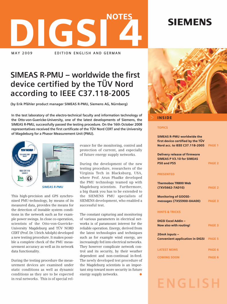
DIGSI 4 s NOTES MAY 2009 EDITION ENGLISH AND GERMAN ENGLISH This high-precision and GPS synchro- nised PMU-technology, by means of its measured data, provides the means for the detection of instable system condi- tions in the network such as for exam- ple power swings. In close co-operation, scientists of the Otto-von-Guericke- University Magdeburg and TÜV NORD CERT (Prof. Dr. Ulrich Adolph) developed a new testing procedure. It makes possi- ble a complete check of the PMU meas- urement accuracy as well as its network data functionality. During the testing procedure the meas- urement devices are examined under static conditions as well as dynamic conditions as they are to be expected in real networks. This is of special rel- SIMEAS R-PMU – worldwide the first device certified by the TÜV Nord according to IEEE C37.118-2005 (by Erik Pfähler product manager SIMEAS R-PMU, Siemens AG, Nürnberg) INSIDE TOPICS SIMEAS R-PMU worldwide the first device certified by the TÜV Nord acc. to IEEE C37.118-2005 PAGE 1 Delivery release of firmware SIMEAS P V3.10 for SIMEAS P50 and P55 PAGE 2 PRESENTED Thermobox TR800 Web (7XV5662-7AD10) PAGE 2 Monitoring of GOOSE- messages (7XS5900-0AA00) PAGE 3 HINTS & TRICKS DIGSI Excel Addin – Now also with routing! PAGE 3 20mA inputs – Convenient application in DIGSI PAGE 5 LATEST NEWS PAGE 6 COMING SOON PAGE 6 evance for the monitoring, control and protection of current, and especially of future energy supply networks. During the development of the new testing procedure, researchers of the Virginia Tech in Blacksburg, USA, where Prof. Arun Phadke developed the PMU technology teamed up with Magdeburg scientists. Furthermore, a big thank you has to be extended to the SIEMENS PMU specialists of SIEMENS development, who enabled a successful test. The constant capturing and monitoring of various parameters in electrical net- works is of paramount interest for the reliable operation. Energy, derived from the latest technologies and techniques such as for example wind energy, are increasingly fed into electrical networks. They however complicate network con- trol and its security, by their weather dependent and non-continual in-feed. The newly developed test procedure of the Magdeburg scientists is an impor- tant step toward more security in future energy supply networks. In the test laboratory of the electro-technical faculty and information technology of the Otto-von-Guericke-University, one of the latest developments of Siemens, the SIMEAS R-PMU, successfully passed the testing procedure. On the 16th October 2008 representatives received the first certificate of the TÜV Nord CERT and the University of Magdeburg for a Phasor Measurement Unit (PMU). SIMEAS R-PMU
Transcript of digsi o1 2oo9 enw1.siemens.ch/home/ch/de/energy/produkte/produktna… · · 2012-10-153 DIGSI 4...
DIGSI 4 sNOTES
MM AA YY 22 00 00 99 EE DD II TT II OO NN EE NN GG LL II SS HH AA NN DD GG EE RR MM AA NN
ENGLISH
This high-precision and GPS synchro-nised PMU-technology, by means of itsmeasured data, provides the means forthe detection of instable system condi-tions in the network such as for exam-ple power swings. In close co-operation,scientists of the Otto-von-Guericke-University Magdeburg and TÜV NORDCERT (Prof. Dr. Ulrich Adolph) developeda new testing procedure. It makes possi-ble a complete check of the PMU meas-urement accuracy as well as its networkdata functionality.
During the testing procedure the meas-urement devices are examined understatic conditions as well as dynamicconditions as they are to be expectedin real networks. This is of special rel-
SIMEAS R-PMU – worldwide the firstdevice certified by the TÜV Nordaccording to IEEE C37.118-2005(by Erik Pfähler product manager SIMEAS R-PMU, Siemens AG, Nürnberg)
INSIDE
TOPICS
SIMEAS R-PMU worldwide the
first device certified by the TÜV
Nord acc. to IEEE C37.118-2005 PAGE 1
Delivery release of firmware
SIMEAS P V3.10 for SIMEAS
P50 and P55 PAGE 2
PRESENTED
Thermobox TR800 Web
(7XV5662-7AD10) PAGE 2
Monitoring of GOOSE-
messages (7XS5900-0AA00) PAGE 3
HINTS & TRICKS
DIGSI Excel Addin –
Now also with routing! PAGE 3
20mA inputs –
Convenient application in DIGSI PAGE 5
LATEST NEWS PAGE 6
COMING SOON PAGE 6
evance for the monitoring, control andprotection of current, and especiallyof future energy supply networks.
During the development of the newtesting procedure, researchers of theVirginia Tech in Blacksburg, USA,where Prof. Arun Phadke developedthe PMU technology teamed up withMagdeburg scientists. Furthermore,a big thank you has to be extended tothe SIEMENS PMU specialists ofSIEMENS development, who enabled asuccessful test.
The constant capturing and monitoringof various parameters in electrical net-works is of paramount interest for thereliable operation. Energy, derived fromthe latest technologies and techniquessuch as for example wind energy, areincreasingly fed into electrical networks.They however complicate network con-trol and its security, by their weatherdependent and non-continual in-feed.The newly developed test procedure ofthe Magdeburg scientists is an impor-tant step toward more security in futureenergy supply networks.
In the test laboratory of the electro-technical faculty and information technology ofthe Otto-von-Guericke-University, one of the latest developments of Siemens, theSIMEAS R-PMU, successfully passed the testing procedure. On the 16th October 2008representatives received the first certificate of the TÜV Nord CERT and the Universityof Magdeburg for a Phasor Measurement Unit (PMU).
SIMEAS R-PMU

2 May 2009 DIGSI 4
TOPICS
Thermobox TR800 Web (7XV5662–7AD10)
(by Klaus-Dieter Müller, Technical Specialist, Siemens AG, Nürnberg)
Furthermore, temperatures can be simulated,to test the thermo-function in the SIPROTECdevices.
The TR800 has a wide range power supply from24 V-250 V DC and 115/230 V AC as well as analarm relay. Sensor failure or sensor short cir-cuit are alarmed and transmitted via protocol tothe SIPROTEC-device.
Alternatively to thermo sensors, 8 analog values 0/4-20 mA DC and 0-10V DC may be measured. The output can be scaled and the designation(C°, V, A, %) can be adapted in the TR800. The transmission to the SIPRO-TEC-device however takes place via the RTD-protocol in temperature for-mat. 6 of the 8 analog sensor values are available there. With 2 TR800 12values are available. For example 5.5 mA is transferred with a tempera-ture value of 55 in this way and may either be displayed as temperaturein the SIPROTEC-device or compared with a set limit via a thresholdvalue. This allows for the processing of analog dimensions in SIPROTEC-devices with thermo function or their transmission to substation controlunit (e.g. SICAM PAS). In the bay control unit 6MD66 V4.8 (from05/2009) all 8 measuring inputs are available.
Connection is established via a serial RS485 interface. The TR800 is pro-tocol compatible with the TR600 (7XV5662-3AD10, 7XV5662-5AD10) onthe serial RS 485 interface, and transmits the 6 temperatures in the sameformat. In this mode, the TR800 can replace theTR600.
In the case of machine protection 7SK80 the connection may alterna-tively be made via the Ethernet interface Port A. Three conductor ther-mo elements are supported. For the dual conductor connection themeasured line resistance can be compensated for by a software setting.
The Thermobox TR800 Web has 8 measuring/sensor inputs and is ableto capture 8 temperatures via PT100- (Ni100 and Ni120) elements. Themeasuring values 1-6 may be transmitted to SIPROTEC 4 devices withthermo function via protocol. Two universal relays with together 12measuring inputs can be connected.
Delivery release of firmware SIMEAS P V3.10 for SIMEAS P50 and P55
(by Rogerio Boleta, Product Manager Power Quality, Siemens AG, Nürnberg)
It contains the following changes and upgrades:• Control of analog outputs via Modbus RTU/ASCII and Profibus DP• New: Configuration option for calculation/measurement for UEN
(Zero Sequence Voltage/Neutral Voltage)• Correction of power calculation in “4-wire-3-phase balanced”
network connection• Correction of setting parameter Energy P Total in the P50 via
SIMEAS P PAR• Correction of unexpected data transfer interruption during down-
load of mean values via SIMEAS P PAR
INFO
The manual of the devices SIMEAS P50/55 can be downloaded from our Internet page at
www.powerquality.de.
PRESENTED
The Thermobox TR800 Web
The new Firmware V3.10 for SIMEAS P50 and P55 has been released and replaces die V3.02.
INFO
Detailed information (e.g. settings of thermofunctions in the devices, protocols etc.) may beobtained from the applicable device manualsand the extensive application description ofthe TR 800 Web operation together withSIPROTEC devices in the Internet at
www.siprotec.com> Accessories > 7XV5662-xAD.

3DIGSI 4 May 2009
Monitoring of GOOSE-messages (7XS5900-0AA00)
(by Markus Spangler, Product Management, Siemens AG, Nürnberg)
From April there will finally be a user-friendly special tool available for themonitoring of GOOSE messages. The main difference to programs already avai-lable is the focussing on the application level.
The logical node structures are of cour-se available, but are not the focus ofinterest. Thereby it is now finally possi-ble to check at a glance at the applica-tion layout, whether all configuredmessages are accessible on the stationbus.
This is made possible with a applica-tion view adapted to the DIGSI stationconfigurator. Here the real-time avai-lability of the GOOSE messages is dis-played in colour. The link to a Demoversion will be available from Mayonwards under www.siprotec.com >Software.
The GOOSE Inspector in action
HINTS & TRICKS
DIGSI Excel Addin – Now also with routing!
(by Johannes Bruss, expert DIGSI, Siemens AG, Nürnberg)
DIGSI provides, by means of the XML-Export, an effective tool to export protectionparameters as well as signal routing in a readable format
The DIGSI Excel Addin provides the means to convert this XML file to an Excel for-mat. In this manner, protection parameters can conveniently be changed, even ifDIGSI is not installed on the PC. In the current Version 2.0 it is now possible to, apartfrom protection parameters, also view and change all signal allocations.
How it’s done? Quite simple!In the DIGSI Manager select the device that has to be exported with a right clickand select “export device”. In the export dialog enter the destination path as wellas file format “DIGSI 4 transfer file (*.xml)”.
Now open Excel. Click on DIGSI in the tool bar and then on “create new sheet forXML”. If you have not yet installed the DIGSI Addin the selection in the toolbar willnot be visible. From our Internet page www.siprotec.com the Addin may be down-loaded free of charge.
In the following dialog, select a storage path for the XML export file and select aname for the device. This is required if the setting sheet will be used for more thanone device.
Exportieren aus DIGSI 4
The Excel Addin menu

4 May 2009 DIGSI 4
Here you also select what has to be im-ported. You have the choice of import-ing the settings, routing information orboth to Excel.
If you selected import of both options,in Excel there will be a separation intotwo sides. The first side contains theprotection settings, while the signalrouting is on the second side. The dis-play is very similar to the well-knowncompact view of the matrix in DIGSI.Here the alarms and measured valuesare however combined in a single view.-> see picture top right
A separation into three or, in the eventof a system interface, four columns isshown. The example in the diagramabove shows the routing of a protectiondevice without system interface. Thethree main columns are marked red. Column 1: Listing of the signals with in-formation number and typeColumn 2: The source of the signal isdefined here. The available selectionsare binary input, function key, as wellas the user defined logic CFC.Column 3: The destination of the signalis found here. This may for example befor further processing of the informa-tion in CFC or the activation of an LED.Furthermore, the allocation of whichsignals should appear in the specialevent logs is done here. Column 4: If a system interface is avail-able the corresponding settings arefound here. The setting options are vis-ible in accordance with the applied pro-tocol.
HINTS & TRICKS
Of course you do not only have themeans of viewing the routing, it can alsobe modified. The colour of the cellshows, whether the routing of a signalcan be changed. If the cell is shaded yel-low/orange, routing is possible. If youfor example want to route the signal“device TRIP” to binary output 4, justenter “U4” into the column of the binaryoutputs. The binary output 4 is thenactive, as long as the signal “deviceTRIP” is picked up.
Of course one can not only change avail-able signals, one can also create com-pletely new information. For this pur-pose, under the button DIGSI and rout-ing in the toolbar select the option “addnew information”. A list of all availableinformation types is displayed.
In this example a single point informa-tion is selected. Double-click on “ON/OFF(SP)” and then select a suitable cell fromthe information row. For this purpose,initially click on the symbol marked redin the diagram and subsequently on thedesired cell. Then you can also selectwhether the new information should beinserted above or below this cell.
New groups may also be inserted. Thisis also done via the DIGSI button in the toolbar. Under the option “routing” theselection “add information group” is available. In the following dialog, initially
Creating a setting sheet for a device Routing matrix displayed in Excel
Selecting the cell
Inserting new information

select the device or the designationthat must obtain the new group. Thenenter the desired group name.
The setting page is readily adapted tothe specific requirements. Settingsthat are not needed by the applicationmay be directly removed from the set-ting sheet. Your setting sheet maytherefore be restricted to the settingsthat are really needed. In this way younever loose the overview!
5DIGSI 4 May 2009
Adding a new information group
20mA inputs – Convenient application in DIGSI
(by Johannes Bruss, expert DIGSI, Siemens AG, Nürnberg)
As with the protection devices 7SJ633,7SJ636, 7UM62 as well as most of thebay RTUs 6MD6 more and more devicesprovide 20mA inputs. These may beconveniently applied with DIGSI.Routinely, these are pre-set with motorprotection to provide conversion topressure (input 1) and temperature(input 2). This can however easily bemodified.
To obtain display of the desired meas-ured value at the 20mA-input, with suit-able dimension, first enter the matrix.Open the information catalog and select"measured value (MV)". Name this meas-ured value (e.g. current).
Route the dimensionless input of theconverter to "destination –> CFC" andthe newly created measured value to"source –> CFC". With a right click on thenew measured value, the properties dia-log is opened.
Three settings can be applied here:• Dimension: Enter the desired dimen-
sion (e.g. kA)• Conversion factor: 1000 corresponds
to e.g. 10 times the original value• Decimal places
In the CFC chart of the device, a pre-defined CFC chart („Transducer 20mAInput“) can be found.
It can be used to convert the input valueand may be adapted to suit the applica-tion.
Practical applications are the determi-nation of threshold with the module“Upper_Setpoint“ and “Lower_Setpoint“,as well as suppression of measurementtolerances with very small measuredvalues by means of the “ZERO_POINT“or “LIVE_ZERO“ modules. In the exam-ple shown, the ZERO_POINT module isused to suppress measured valuesbelow 5% of the measurement range.
Now the chart must be compiled andtransferred to the device.
Selection of the information type measurement
The correct routing is essential
The CFC provides a flexible correlation and processing of the measurements
The object properties allow the setting of
the dimension and translation factor

6 May 2009 DIGSI 4
Training Courses (City: Nuremberg) – an excerpt from the current program
11.05.-12.05.09 Basics of communication networks and the application in power transmission and distribution22.06.-26.06.09 Principles of system protection technology29.06.-01.07.09 DIGSI 4 – Basic course – Protection and control functions02.07.-03.07.09 SIGRA – Efficient interpretation of fault records06.07.-08.07.09 DIGSI 4 – Advanced course – Protection- and control functions09.07.-10.07.09 DIGSI 4 IEC 61850 – Configuration of substations and devices20.07.-22.07.09 SIPROTEC 4 – Relay secondary testing of the product families 7SJ, 7SA and 7UT/SD
with the OMICRON test system (Germany)27.07.-29.07.09 SIPROTEC 4 – Distributed busbar protection 7SS52 - Intensive course04.08.-07.08.09 SIPROTEC 4 – Using numerical machine and motor protection05.08.-06.08.09 Engineering of bay controllers 6MD66 with IEC 6185007.09.-11.09.09 Principles of system protection technology07.09.-11.09.09 SIPROTEC 4 – Protection devices for expert engineers07.09.-08.09.09 Basics of power quality15.09.-18.09.09 SIPROTEC 4 – Using numerical protection devices16.09.-17.09.09 Basics, application and commissioning of IEC 61850 communication networks28.09.-30.09.09 Application and practice of numerical recording system SIMEAS R
Additional courses and information at www.siemens.com/power-academy-td.
COMING SOON
IMPRESSUMEditorial & Publishing: Siemens AG; Energy Sector (PTD): Thomas Jachmann, Product Manager; Telefon: +49 911 433-7238; E-mail: [email protected];Download/Info: www.siprotec.com; Support: www.siemens.com/ptd-support; Training: www.siemens.com/power-academy-td; Layout: New Orange Design;Stylesheet: Publicis Kommunikations Agentur Erlangen; Printed in Germany © Siemens AG 2009
Latest News
Qualification of another switch ven-dor for the use in IEC61850 networks.
Apart from Ruggedcom, a wellknown Ethernet switch manufactur-er, two device ranges for applicationin IEC61850 networks manufacturedby the company Hirschmann havenow been qualified following exten-sive system and performance tests.
The application with electrical andoptical Ethernet modules in SIPRO-TEC 4 is possible and in particularoptical SIPROTEC ring structureshave been successfully tested. Pre-viously only Ruggedcom could beapplied here.
With the release of the Switch - Software Version 5.0 the Hirschmann device variantsRSR20/30 as well as Mach 1000 can be applied in large, complex IEC61850 networks.
With Version 5.0 Hirschmann reduces the switch-over times for the redundantcommunication in an optical ring compared with the RSTP standard significantly,so that together with SIPROTEC devices, the proven switch-over time in ms range isobtained in optical rings. Up to now this was only possible with Ruggedcom-switch-es. The release of this software version is scheduled for April 2009. During theplanning stage of future projects, these new product ranges may be consideredwith immediate effect.
These tests were also successfully repeated during 2008 with Ruggedcom – switch-es, to avoid problems with newer Firmware versions in IEC 61850 projects. Thetested and recommended software version is ROS 3.4.8 in this case.
The desired Firmware version can be supplied ex works with the switch byRuggedcom and Hirschmann. For this purpose, the software version (-V34 for 3.4)is appended to corresponding order number of the Ruggedcom switch. Hirschmannallows for direct entry of the version the product code of the device

DIGSI 4 sNOTES
MM AA II 22 00 00 99 EE DD II TT II OO NN EE NN GG LL II SS HH AA NN DD GG EE RR MM AA NN
DEUTSCH
Die hochpräzise und GPS-synchroni-sierte PMU-Technologie bildet mitIhren Messdaten die Grundlage zurErkennung von instabilen Systemzu-ständen im Netz wie z.B. Leistungs-pendelungen. In enger Kooperationentwickelten nun Wissenschaftler derOtto-von-Guericke-Universität Mag-deburg und TÜV NORD CERT (Prof. Dr.Ulrich Adolph) ein neuartiges Testver-fahren. Es ermöglicht eine vollständi-ge Prüfung der PMU-Messgenauigkeitsowie deren Netzdatenfunktionalität.
Bei dem Testverfahren werden Mess-geräte sowohl unter statischen alsauch unter dynamischen Bedingun-gen, wie sie in realen Netzen zu er-warten sind, untersucht. Dies ist vonbesonderer Bedeutung für die Über-
SIMEAS R-PMU weltweit das ersteGerät zertifiziert vom TÜV Nord nachIEEE C37.118-2005(Von Erik Pfähler, Produktmanager SIMEAS R-PMU, Siemens AG, Nürnberg)
INHALT
AKTUELLES
SIMEAS R-PMU weltweit das
erste Gerät zertifiziert vom TÜV
Nord nach IEEE C37.118-2005 SEITE 1
Lieferfreigabe der Firmware
SIMEAS P V3.10 für SIMEAS P50
und P55 SEITE 2
VORGESTELLT
Thermobox TR800 Web
(7XV5662-7AD10) SEITE 2
Monitoring von GOOSE-
Nachrichten (7XS5900-0AA00) SEITE 3
TIPPS & TRICKS
DIGSI Excel Addin –
Jetzt wird auch rangiert! SEITE 3
20mA Eingänge –
Clever in DIGSI nutzen SEITE 5
LETZTE MELDUNGEN SEITE 6
DEMNÄCHST SEITE 6
wachung, Steuerung und den Schutzheutiger, vor allem aber zukünftigerEnergieversorgungsnetze.
Bei der Entwicklung des neuartigenTestverfahrens standen den Magde-burger Wissenschaftlern Forscher derVirginia Tech in Blacksburg, USA, ander Prof. Arun Phadke die PMU-Tech-nologie entwickelte, zur Seite. Des Wei-teren gilt ein besonderer Dank denSIEMENS PMU-Spezialisten der Sie-mens Entwicklung, die einen erfolgrei-chen Test ermöglichten.
Die stetige Erfassung und Überwachungunterschiedlichster Parameter in elek-trischen Netzen ist vor allem für derenzuverlässigen Betrieb von großem Inte-resse. Energien, gewonnen aus neues-ten Technologien und Verfahren, wiez.B. die Windenergie, werden zuneh-mend in die elektrischen Netze einge-speist, verkomplizieren jedoch durchderen wetterabhängige und nicht konti-nuierliche Energieeinspeisung die Netz-führung und deren Sicherheit. Das neuentwickelte Testverfahren der Magde-burger Wissenschaftler ist ein wichtigerSchritt hin zu mehr Sicherheit zukünf-tiger Energieversorgungsnetze.
Im Testlabor der Fakultät für Elektrotechnik und Informationstechnik der Otto-von-Guericke-Universität hat eine der neuesten Entwicklungen der Firma Siemens, dieSIMEAS R-PMU, erfolgreich ein Testverfahren durchlaufen. Dafür nahmen Firmen-vertreter am 16. Oktober 2008 das erste Zertifikat des TÜV NORD CERT und der UniMagdeburg für eine Phasor Measurement Unit (PMU) entgegen.
SIMEAS R-PMU

2 Mai 2009 DIGSI 4
AK TUELLES
Thermobox TR800 Web (7XV5662–7AD10)
(Von Klaus-Dieter Müller, Fachberater, Siemens AG, Nürnberg)
werden. Ferner können Temperaturen simuliertwerden, um z.B. die Thermofunktion in denSIPROTEC-Geräten zu testen.
Das TR800 verfügt über eine Weitbereichsstrom-versorgung von 24V-250 V DC und 115/230 VAC und ein Störmelderelais. Sensorbruch oderSensorkurzschluss werden gemeldet und perProtokoll zum SIPROTEC-Gerät übertragen.
Alternativ zu Thermo-Sensoren können 8 Analoggrößen 0/4-20 mA DCund 0-10 V DC gemessen werden. Die Ausgabe kann skaliert und die Be-nennung (C°, V, A, %) im TR800 angepasst werden. Die Übertragungzum SIPROTEC-Gerät erfolgt jedoch über das RTD-Protokoll imTemperaturformat und es sind dort 6 der 8 analogen Sensorwerte ver-fügbar. Mit zwei TR800 auch 12 Werte. So werden z.B. 5,5 mA mit demTemperaturwert 55 übertragen und können als Temperatur im SIPRO-TEC-Gerät angezeigt oder über einen Schwellwert auf Grenzen hin abge-fragt werden. Dies ermöglicht die Weiterverarbeitung von Analoggrö-ßen in SIPROTEC-Geräten mit Thermofunktion oder deren Übertragungzur Leittechnik. Im Feldleitgerät 6MD66 V4.7 (ab 05/2009) stehen alle 8analogen Messeingänge zur Verfügung.
Der Anschluss erfolgt über eine serielle RS485-Schnittstelle. Das TR800ist protokollkompatibel zum TR600 (7XV5662-2AD10, 7XV5662-5AD10)an der seriellen RS 485 Schnittstelle und überträgt die 6 Temperaturenim selben Format. In diesem Modus kann TR800 das TR600 ersetzen.
Beim Motorschutz 7SK80 kann der Anschluss alternativ über die optio-nale Ethernetschnittstelle Port A erfolgen. Es werden 3-Leiter Thermo-Elemente unterstützt. Für den 2-Leiter Anschluss kann der gemesseneLeitungswiderstand durch eine Einstellung in der Software kompensiert
Die Thermobox TR800 Web hat 8 Mess- / Sensoreingänge und kann überPT100- (Ni100 und Ni120) Elemente bis zu 8 Temperaturen erfassen. ZuSIPROTEC 4 Geräten mit Thermofunktion können die Messwerte 1-6 perProtokoll übertragen und dort in Thermofunktionen verwendet wer-den. Zwei Universal Relais mit zusammen 12 Messeingängen könnenangeschlossen werden.
Lieferfreigabe der Firmware SIMEAS P V3.10 für SIMEAS P50 und P55
(Von Rogerio Boleta, Produktmanager Power Quality, Siemens AG, Nürnberg)
Sie bringt die folgenden Änderungen und Erweiterungen mit:• Steuerung von Analogausgängen durch Modbus RTU/ASCII
und Profibus DP Protokoll• Neu: Konfiguration für Berechnung / Messung von UEN
(Null Spannung / Neutralleiter)• Korrektur in der Leistungsberechnung für “Vierleiter Drehstrom
gleich Belastung“ Anschluss• Korrektur in der Einstellung für Energie P Total in P50 via
SIMEAS P PAR• Behebung von unerwarteten Unterbrechungen in der Datenüber-
tragung während des Downloads der Mittelwerte in SIMEAS P PAR
INFO
Das SIMEAS P50/P55 Gerätehandbuch und die Betriebsanleitung finden Sie auf unsererInternetseite
www.powerquality.de.
VORGESTELLT
Die Thermobox TR800 Web
Die neue Firmware V3.10 für SIMEAS P50 und P55 ist freigegeben und ersetzt die V3.02.
INFO
Detaillierte Informationen (z.B. Einstellungender Thermofunktion in den Geräten, Messenvon Analoggrößen, Protokolle usw.) entneh-men Sie bitte den gerätespezifischen Hand-büchern und den ausführlichen Applikatio-nen zum TR800 zusammen mit SIPROTEC–Geräten im Internet unter:
www.siprotec.de > Zubehör > 7XV5662-xAD

3DIGSI 4 Mai 2009
Monitoring von GOOSE-Nachrichten (7XS5900-0AA00)
(Von Markus Spangler, Produktmanagement, Siemens AG, Nürnberg)
Ab April wird es mit dem GOOSE Inspector endlich ein anwendertauglichesMonitoring-Werkzeug zur Überwachung von GOOSE-Nachrichten geben. Derwesentliche Unterschied zu bereits verfügbaren Programmen ist die möglicheFokussierung auf Applikationsebene.
Die logischen Knotenstrukturen sindnatürlich verfügbar, treten aber in denHintergrund. Damit besteht nun end-lich die Möglichkeit, mit einem Blickauf Applikationsebene zu überprüfen,ob alle konfigurierten Nachrichten aufdem Stationsbus verfügbar sind.
Möglich wird dies durch eine demDIGSI-Stationskonfigurator angepassteApplikationssicht. Hier wird in Echt-zeit die Verfügbarkeit der GOOSE-Nachrichten farblich dargestellt. DerLink zu einer Demoversion wird ab Maiunter: www.siprotec.de > Programmezur Verfügung stehen.
Der GOOSE Inspector im Einsatz beim Moni-
toring
TIPPS & TRICKS
DIGSI Excel Addin – Jetzt wird auch rangiert!
(Von Johannes Bruss, Fachberater DIGSI, Siemens AG, Nürnberg)
DIGSI bietet mit Hilfe des XML-Exports ein wirkungsvolles Tool, um Schutzparame-ter sowie Rangierungen in einem lesbaren Format zu exportieren.
Das DIGSI Excel Addin gibt Ihnen die Möglichkeit, diese XML-Datei in ein Excel-Format zu überführen. So lassen sich Schutzparameter komfortabel ändern, auchohne DIGSI auf dem Rechner installiert zu haben. In der aktuellen Version 2.0 lassensich nun neben Schutzparametern auch sämtliche Rangierungen betrachten undnatürlich auch verändern.
Wie das geht? Ganz einfach!Wählen Sie im DIGSI Manager das zu exportierende Gerät mit einem Rechtsklickaus und wählen Sie „Gerät exportieren“. Im Export Dialog geben Sie den Spei-cherort sowie das Dateiformat “DIGSI 4 Transferdatei (*.xml)” an.
Öffnen Sie nun Excel. Klicken Sie auf den Reiter „DIGSI“ und dann auf „NeuesEinstellblatt“. Sollten sie das DIGSI Addin noch nicht installiert haben, so könnenSie dieses auf unserer Internetseite www.siprotec.de kostenlos herunterladen.
Im folgenden Dialog wählen Sie bitte den Speicherort Ihrer XML-Exportdatei ausund geben einen Bezeichner für Ihr Gerät an. Dieser wird gebraucht, wenn Sie einEinstellblatt für mehrere Geräte verwenden. Hier wählen Sie auch aus, was Sie im-
Exportieren aus DIGSI 4
Das Excel Addin Menü

4 Mai 2009 DIGSI 4
portieren möchten. Sie haben die Wahl,die Parameter, die Rangierungen odergleich beides in Excel zu importieren.
Wenn Sie den Komplettimport ange-wählt haben, sehen Sie nun in Exceleine Aufteilung auf zwei Seiten. Dieerste Seite beinhaltet die Schutzpara-meter und auf Seite 2 finden Sie dieRangierungen. Die Ansicht ähnelt da-bei sehr stark der aus DIGSI bekanntenKurzansicht der Matrix. Im Unterschieddazu sind hier jedoch Meldungen undMesswerte zu einer Ansicht zusammen-gefügt. -> siehe Bild rechts oben
Man findet eine Aufteilung in drei bzw.bei Verwendung einer Systemschnitt-stelle vier Spalten. Das obige Bild zeigtbeispielhaft die Rangierungen für einSchutzgerät ohne Systemschnittstelle.Die drei Hauptspalten sind rot markiert.Spalte 1: Auflistung der Meldungen mitInformationsnummer und -typSpalte 2: Hier wird die Quelle der Mel-dung definiert. Zur Auswahl stehen un-ter anderem Binäreingänge, Funktions-tasten sowie das Logikprogramm CFC.Spalte 3: Hier findet man das Ziel derMeldung. Dies kann z.B. eine Weiter-verarbeitung der Information im CFCoder eine Belegung einer LED sein. Zu-dem wird hier definiert, welche Meldun-gen in spezielle Meldepuffer aufgenom-men werden sollen.Spalte 4: Bei Verwendung der System-schnittstelle findet man hier zugehöri-ge Einstellungen. Die Parameter werdenentsprechend dem Protokoll einge-blendet.
TIPPS & TRICKS
Natürlich haben Sie nicht nur die Mög-lichkeit, sich die Rangierungen anzuse-hen, Sie können sie auch ändern. Die Far-be der Zellen gibt an, ob eine Meldungprinzipiell rangiert werden kann. Ist dieZelle gelb/orange hinterlegt, ist eine Ran-gierung möglich. Möchten Sie z.B. dieMeldung „Gerät AUS“ auf Binärausgang 4rangieren, tragen Sie einfach „U4“ in derSpalte der Binärausgänge ein. Damit istder Binärausgang 4 aktiv, solange dieMeldung „Gerät AUS“ ansteht. Selbstver-ständlich kann man nicht nur vorhande-ne Meldungen ändern, sondern es lassensich auch komplett neue Informationenerzeugen. Wählen Sie dazu im Reiter„DIGSI“ unter „Rangierungen“ den Punkt„Information einfügen“. Es folgt eine Auf-listung sämtlicher Informationstypen.
In unserem Beispiel wählen wir eine Ein-zelmeldung. Doppelklicken Sie auf „KOM/GEH (EM)“ und wählen Sie anschließendeine passende Zelle aus einer Informa-tionszeile. Dazu klicken Sie zunächst aufdas im Bild rot markierte Symbol undanschließend auf die gewünschte Zelle.Anschließend können Sie noch auswäh-len, ob die neue Information ober- oderunterhalb dieser Zelle eingefügt werdensoll.
Neue Gruppen können ebenfalls eingefügt werden. Dies funktioniert wieder überden Reiter „DIGSI“. Unter „Rangierungen“ finden Sie den Punkt „Informationsgruppe
Erstellen eines Einstellblatts für Geräte
Die Rangierungsmatrix in Excel
Auswahl der Zelle
Einfügen neuer Informationen

anlegen“. Im folgenden Dialog wählenSie zunächst das Gerät bzw. den Be-zeichner, dem die neue Gruppe zuge-ordnet werden soll. Anschließend gebenSie noch den gewünschten Gruppenna-men an.
Das Einstellblatt lässt sich sehr ein-fach an die jeweiligen Bedürfnisseanpassen. Parameter, die für Ihre An-wendung nicht benötigt werden, kön-nen direkt aus dem Einstellblatt ge-löscht werden.
Ihr Einstellblatt lässt sich damit auf dieEinstellungen reduzieren, die Sie wirk-lich benötigen. So verlieren Sie nie mehrden Überblick!
5DIGSI 4 Mai 2009
Hinzufügen einer neuen Informationsgruppe
20mA Eingänge – Clever in DIGSI nutzen
(Von Johannes Bruss, Fachberater DIGSI, Siemens AG, Nürnberg)
Mit den Schutzgeräten 7SJ633, 7SJ636,7UM62 sowie den meisten Feldleitgerä-ten 6MD6 bieten immer mehr Geräte20mA Eingänge. Diese lassen sich inDIGSI clever nutzen. Standardmäßig sindsie beim Motorschutz bereits so einge-stellt, dass eine Umwandlung in Druck(Eingang 1) und Temperatur (Eingang 2)erfolgt. Doch dies lässt sich ganz einfachanpassen.
Um sich den gewünschten Messwert des20mA-Eingangs mit der passenden Ein-heit anzeigen zu lassen, gehen Sie bittezunächst in die Matrix. Öffnen Sie denInformationskatalog und wählen Sie „Mess-wert (MWB)”. Geben Sie dem Messwerteinen passenden Namen (z.B. Strom).
Setzen Sie jetzt den Rohwert des Mess-umformers auf „Ziel –> CFC” und den neuerstellten Messwert auf „Quelle –> CFC”.Mit Rechtsklick auf den neuen Messwertkommen Sie zu den Eigenschaften.
Hier gibt es drei Einstellwerte:• Dimension: Geben Sie hier die ge-
wünschte Einheit an (z.B. kA)• Umrechnungsfaktor: 1000 entspricht
z.B. dem 10fachen Ursprungswert• Nachkommastellen
In den CFC Plänen des Gerätes finden Sieden vorgefertigten CFC Plan („Transdu-cer 20mA Input“) der zur Umrechnung
des Eingangswerte dient.
Diesen können Sie Ihren Bedürfnissenanpassen.
Sinnvolle Anwendung ist sicherlich dieFestlegung von Grenzwerten über die Bau-steine „Upper_Setpoint” und „Lower_Setpoint“, sowie eine Unterdrückung vonMessungenauigkeiten bei sehr kleinenMesswerten mittels des „ZERO_POINT“oder „LIVE_ZERO“ Bausteins. Im gezeig-ten Beipiel werden z.B. durch denZERO_POINT Baustein erst Werte ab ca.5% des Messbereichs angezeigt.
Jetzt müssen Sie den Plan nur noch kom-pilieren und die neuen Parameter in dasGerät laden.
Auswahl des Informationstyps "Messwert"
Die richtige Rangierung ist natürlich wichtig
In den Objekteigenschaften kann man
Dimension und Umrechung einstellen
Der CFC erlaubt eine flexible Zuordnung und Bearbeitung der Messwerte

6 Mai 2009 DIGSI 4
Trainingsangebote (Ort: Nürnberg) – ein Auszug aus dem aktuellen Programm
04.05.-08.05.09 Prinzipien digitaler Netzschutzsysteme04.05.-08.05.09 SIPROTEC 4 – Schutztechnik für Service Ingenieure11.05.-13.05.09 DIGSI 4 – Grundkurs – Schutz- und leittechnische Funktionen11.05.-13.05.09 Strom- und Spannungswandler in Theorie und Praxis18.05.-20.05.09 Praktische Anwendung des Distanzschutzes25.05.-27.05.09 SIPROTEC 4 – Dezentraler Sammelschienenschutz 7SS52 – Intensivkurs15.06.-17.06.09 DIGSI 4 – Grundkurs – Schutz- und leittechnische Funktionen15.06.-16.06.09 Grundwissen für die Schutztechnik17.06.-18.06.09 Grundlagen, Anwendung und IBS von IEC 61850- Kommunikationsnetzen18.06.-19.06.09 Anwendung und Praxis der Systeme SIMEAS Q, P und T22.06.-24.06.09 Praktische Anwendung des Differentialschutzes06.07.-07.07.09 Grundlagen der Power Quality13.07.-15.07.09 DIGSI 4 – Grundkurs – Schutz- und leittechnische Funktionen13.07.-17.07.09 SIPROTEC 4 – Schutztechnik für Service Ingenieure23.07.-24.07.09 Projektierung des Feldleitgerätes 6MD66 mit IEC 6185028.07.-31.07.09 SIPROTEC 4 – Anwendung und Praxis
Weitere Kurse und Information unter www.siemens.com/power-academy-td.
DEMNÄCHST
IMPRESSUMEditorial & Publishing: Siemens AG; Energy Sector (PTD): Thomas Jachmann, Produktmanager; Telefon: +49 911 433-7238; E-mail: [email protected];Download/Info: www.siprotec.de; Support: www.siemens.com/ptd-support; Training: www.siemens.com/power-academy-td; Layout: New Orange Design;Stylesheet: Publicis Kommunikations Agentur Erlangen; Printed in Germany © Siemens AG 2009
Letzte Meldung
Qualifikation eines weiteren Herstel-lers von Switches für den Einsatz inIEC 61850 Netzwerken
Neben Ruggedcom als langjähri-gem Ethernet Switchhersteller,wurde nun auch die Firma Hirsch-mann mit zwei Gerätereihen fürIEC61850 Netzwerke in umfangrei-chen System- und Performance-tests qualifiziert.
Der Einsatz ist zusammen mit elek-trischen und optischen Ethernetmo-dulen in SIPROTEC 4 möglich undinsbesondere optische Siprotec –Ringstrukturen sind erfolgreich ge-testet worden. Hier konnte bisher nurRuggedcom eingesetzt werden.
Mit Freigabe der Switch – Software Version 5.0 können die Hirschmann Gerätevari-anten RSR20/30 oder auch Mach 1000 in großen und komplexen IEC61850 Netz-werken eingesetzt werden.
Mit Version 5.0 reduziert Hirschmann die Umschaltzeiten für die Kommunika-tionsredundanz im optischen Ring gegenüber dem Standard-RSTP signifikant, sodaß in optischen Ringen zusammen mit Siprotec-Geräten nun die bewährten Um-schaltzeiten im ms-Bereich liegen. Diese wurden bisher nur beim Einsatz mitRuggedcom-Switches erreicht. Die Freigabe dieser Softwareversion ist für April2009 vorgesehen. In der Planungsphase für zukünftige Projekte können die neuenGerätereihen ab sofort mit berücksichtigt werden.
Auch für Ruggedcom – Switches wurden diese Tests im Jahr 2008 erfolgreich wie-derholt, um Probleme mit neuen Firmwareversionen in IEC 61850 Projekten zuvermeiden. Die getestete und empfohlene Softwareversion hier ist ROS 3.4.8.
Bei Ruggedcom und Hirschmann kann die gewünschte Firmwareversion bereits abWerk zusammen mit dem Switch geliefert werden. Dazu ist an das Ende der jeweili-gen Bestellnummer von Ruggedcom einfach die Softwareversion (-V34 für 3.4)anzuhängen. Hirschmann erlaubt die direkte Angabe der Bestellnummer im Pro-duktcode des Gerätes.