
Digsi Startup a4 En
62
Edition: 15.10.03 E50417-G1176-C152-A4 DIGSI 4 Start Up Manual What awaits you 1 Installing DIGSI 4 2 Configuring a Power Distribution Structure 3 Modifying the Settings of Protection Functions 4 Allocating Information Items 5 Creating Logic Functions 6 Editing Default and Control Displays 7 Working online 8 Evaluating Fault Records 9 Review 10
Transcript of Digsi Startup a4 En
Edition: 15.10.03
E50417-G1176-C152-A4
DIGSI 4
Start Up
Manual
What awaits you 1Installing DIGSI 4 2Configuring a Power Distribution Structure 3Modifying the Settings of Protection Functions4Allocating Information Items 5Creating Logic Functions 6Editing Default and Control Displays 7Working online 8Evaluating Fault Records 9Review 10

Siemens Aktiengesellschaft Manual No. E50417-G1176-C152-A4
Exclusion of LiabilityWe have checked the contents of this publication and every effort has been made to ensure that the descriptions of both hardware and software are as accurate as possible. However, deviations from the description cannot be completely ruled out, so that no liability can be accepted for any errors or omissions contained in the infor-mation given.The data in this manual are checked regularly and the necessary corrections are included in subsequent editions. We are grateful for any improvements that you care to suggest.Subject to technical modifications.1.00.06
CopyrightCopyright�� Siemens AG 2003 All Rights ReservedDissemination or reproduction of this document, or evaluation and communication of its contents, is not authorized except where ex-pressly permitted. Violations are liable for damages. All rights reserved, particularly for the purposes of patent application or trademark registration.
Registered TrademarksDIGSI® is a registered trademark of SIEMENS AG. Other designa-tions in this manual may be trademarks that if used by third parties for their own purposes may violate the rights of the owner.

Table of Contents
1 What awaits you . . . . . . . . . . . . . . . . . . . . . . . . . . . . . . . . . . . . . . . . . . . . . . . . . . . 1
2 Installing DIGSI 4 . . . . . . . . . . . . . . . . . . . . . . . . . . . . . . . . . . . . . . . . . . . . . . . . . . . 3
3 Configuring a Power Distribution Structure . . . . . . . . . . . . . . . . . . . . . . . . . . . . . 5
4 Modifying the Settings of Protection Functions. . . . . . . . . . . . . . . . . . . . . . . . . . 13
5 Allocating Information Items . . . . . . . . . . . . . . . . . . . . . . . . . . . . . . . . . . . . . . . . . 19
6 Creating Logic Functions . . . . . . . . . . . . . . . . . . . . . . . . . . . . . . . . . . . . . . . . . . . . 25
7 Editing Default and Control Displays . . . . . . . . . . . . . . . . . . . . . . . . . . . . . . . . . . 35
8 Working online. . . . . . . . . . . . . . . . . . . . . . . . . . . . . . . . . . . . . . . . . . . . . . . . . . . . . 41
9 Evaluating Fault Records . . . . . . . . . . . . . . . . . . . . . . . . . . . . . . . . . . . . . . . . . . . . 51
10 Review . . . . . . . . . . . . . . . . . . . . . . . . . . . . . . . . . . . . . . . . . . . . . . . . . . . . . . . . . . . 57
iDIGSI 4 Start UpE50417-G1176-C152-A4

Table of Contents
ii DIGSI 4 Start Up E50417-G1176-C152-A4

What awaits you 1Hello there to our new start-up manual for DIGSI 4. In this book we have put into practice what many of you have been waiting for: a compact overview of basic DIGSI 4 functions, including the optional software modules.
Really Relaxed Especially for you we have created a practice-oriented exercise which we will use to introduce you into the world of DIGSI 4 in an amusing way, (amusing in so far as the editors allow). We have included further information in this exercise that will help you get started with DIGSI 4. And, last but not least, we have heaps of tips and some extra homework to give to the eager among you.
Our start-up manual is structured in a way that dispenses with the need of reading the manual (which, however, would please us most). You can also work through just the exercises. In each chapter the necessary instructions are highlighted by a different background color and can thus be easily spotted.
NoMission Impossible
Within the scope of the exercise, the following behavior is to be implemented in DIGSI 4:
The motor connected to the binary output BO1 of a SIPROTEC 4 device is started by pressing the F1 function key. During the first 10 seconds following the start the settings group B is active. After that there is an automatic switch-over to settings group A. If all motor currents are smaller than 5% of the rated current, settings group B is reactivated. An indication should appear on the display of the SIPROTEC 4 device when the settings group B is active.
Great Expectations Before you get started, however, we will provide a brief overview of what awaits you in this book.
As the first step, which you will generally perform only once, you will install your version of DIGSI 4. Some tips on this topic are in chapter 1 of this book.
Chapter 2 through to Chapter 6 is devoted to our exercise. In order to complete it, the various components of DIGSI 4 are applied: Manager, Device Configuration, Device Matrix, CFC and, last but not least, the Display Editor. As you will probably have imagined by now, we have developed it this way absolutely on purpose. After all, we want to demonstrate to you the versatility of DIGSI 4 and introduce you to all important program modules.
1DIGSI 4 Start UpE50417-G1176-C152-A4
What awaits you
Must-Reading Without further ado we prescribe Chapter 8 as must-reading. This is because we describe there how you get DIGSI 4 to communicate with a SIPROTEC 4 device. After all, communication between DIGSI 4 and SIPROTEC 4 is necessary to eventually transfer all your entries, made while solving our exercise, into the SIPROTEC 4 device.
Encore Chapter 9 is a bonus for all those who already have SIGRA 4 or want it badly after reading this chapter. You can use SIGRA 4 to display, synchronize, and analyses fault records. We will offer you a few morsels of this program to whet your appetite for it.
Review Chapter 10 finally concludes this manual by summing up the work you have accomplished in a compact flow chart.
Call Me If you have further questions on DIGSI 4, please call your local Siemens office, or our hotline:
Phone: ++ 49 (0) 1 80 / 5 24 70 00
Fax: ++ 49 (0) 1 80 / 5 24 24 71
E-mail: [email protected]
Courses Please ask your local Siemens office for information on training courses, or contact our hotline:
Siemens AGPower Transmission and DistributionPower AutomationHumboldtstr. 5990459 NurembergPhone: ++ 49 (0) 9 11 / 4 33-70 05Fax: ++ 49 (0) 9 11 / 4 33-79 29
Tips In each chapter we will provide at least one tip on the current topic. Such a tip could be: Why not use the right mouse button? Right-clicking objects of the Manager or Device Configuration generally opens a context menu which contains related commands and thus spares you the detour via the menu bar.
Homework For all those who like to do additional work we have thought up some homework at the end of each chapter.
2 DIGSI 4 Start Up E50417-G1176-C152-A4

Installing DIGSI 4 2Like any decent program also DIGSI 4 has its own installation routine which will guide you neatly and safely through the installation process. We can therefore move along without showing you every single dialog box that comes up during installation. Rather, this short chapter provides several tips that will pave the way for you to get through the installation as easily as possible. For this purpose we ask ourselves the following questions before starting the installation:
1. How does DIGSI 4 react to already existing software components?
2. What options should you select during the installation?
3. How many cups of coffee must be brewed before starting the installation?
Ancestors If an older version of DIGSI 4 is already installed on the PC, you must uninstall it first. If you have failed to do so, the installation program will give you a friendly reminder to do it now. Like any other software also DIGSI 4 is uninstalled by means of the Control Panel of your Windows operating system. Please DIGSI 4 do not under any circumstances remove it manually from your directory structure. In doing so the entries in the registry file remain unaffected and cause conflicts when the new DIGSI 4 is installed. After successful uninstallation you must restart your PC!
STEP 7 and other Tools
If you intend to run DIGSI 4 in connection with STEP 7 and/or SICAM plusTOOLS, you must install these programs first. In this context, please read the Readme file on the DIGSI 4 installation CD-ROM. It contains information on problems that might be caused if incompatible version releases are used.
Basic Rights When you are installing DIGSI 4 under some Windows operating systems you must possess unlimited administrator rights.
Dependent Internet Explorer Version 4 or higher must be installed on your computer. Otherwise you will not be able to use the DIGSI 4 online help.
3DIGSI 4 Start UpE50417-G1176-C152-A4

Installing DIGSI 4
Option Transactions
During the installation you will be asked successively what program modules and device types to install. Our free advice: Install them all! Thanks to today`s hard disk capacities you don't have to economize on memory space.
High On Caffeine And now to the question of caffeine: You'll need several cups of coffee for the installation. The amount of data is considerable and, what's more, the data must be placed in lots and lots of directories and subdirectories. Thank you for your patience!
4 DIGSI 4 Start Up E50417-G1176-C152-A4

Configuring a Power Distribution Structure 3You have successfully installed DIGSI 4 on your computer, and can't what to get cracking? Then, on your marks, get set...!
Work... We are now at the beginning of our exercise. Although getting started is often considered the most difficult part, you will find that after reading this chapter, working with Digsi is rather simple. We will explain to you in an easy-to-understand way,
� How to create a new project.
� How to add a folder to the project.
� How to integrate a SIPROTEC 4 device into the project.
If you want to do only the first part of our exercise, you should go directly to the section on page 9 highlighted in different background color.
... and Pleasure If you have a bit more time find the answers in this chapter to these additional questions:
� What is the DIGSI 4 Manager capable of?
� What is a project and how does theDIGSI 4 Manager handle it?
� Are there useful configuration tips available?
5DIGSI 4 Start UpE50417-G1176-C152-A4
Configuring a Power Distribution Structure
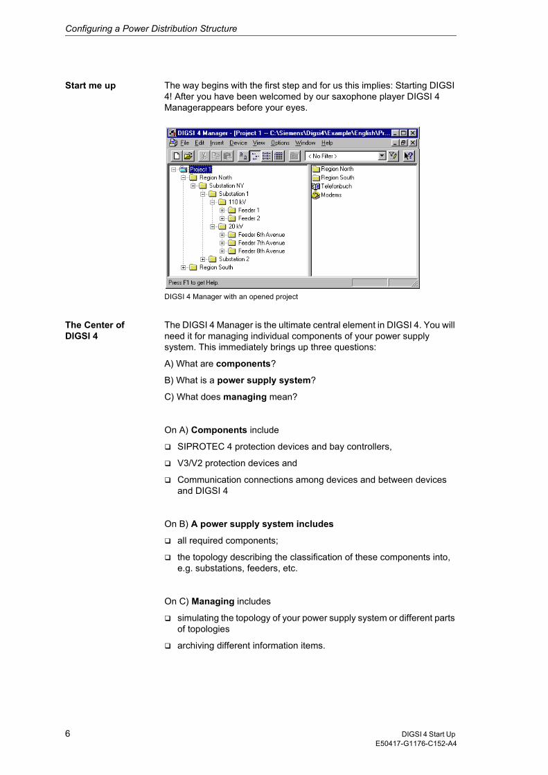
Start me up The way begins with the first step and for us this implies: Starting DIGSI 4! After you have been welcomed by our saxophone player DIGSI 4 Managerappears before your eyes.
DIGSI 4 Manager with an opened project
The Center ofDIGSI 4
The DIGSI 4 Manager is the ultimate central element in DIGSI 4. You will need it for managing individual components of your power supply system. This immediately brings up three questions:
A) What are components?
B) What is a power supply system?
C) What does managing mean?
On A) Components include
� SIPROTEC 4 protection devices and bay controllers,
� V3/V2 protection devices and
� Communication connections among devices and between devices and DIGSI 4
On B) A power supply system includes
� all required components;
� the topology describing the classification of these components into, e.g. substations, feeders, etc.
On C) Managing includes
� simulating the topology of your power supply system or different parts of topologies
� archiving different information items.
6 DIGSI 4 Start Up E50417-G1176-C152-A4
Configuring a Power Distribution Structure
Launching Pad Furthermore the DIGSI 4 Manager serves as platform for furtherActions: You use the DIGSI 4 Manager to start.
� ... DIGSI 4 Configure device. You use this tool to set parameters, route information, display process data and accomplish many more tasks.
� ... DIGSI V3 if you want to operate a V2/V3 protection device integrated in the topology.
� ... communication to a connected SIPROTEC 4 device via different connection types.
Deja vu By the way: If after your first steps in the DIGSI 4 Manager you find that the basic operation is reminiscent of the Windows Explorer, you got the right impression. We have done that on purpose. Being familiar with Windows Explorer means half the battle in working with the DIGSI 4 Manager.
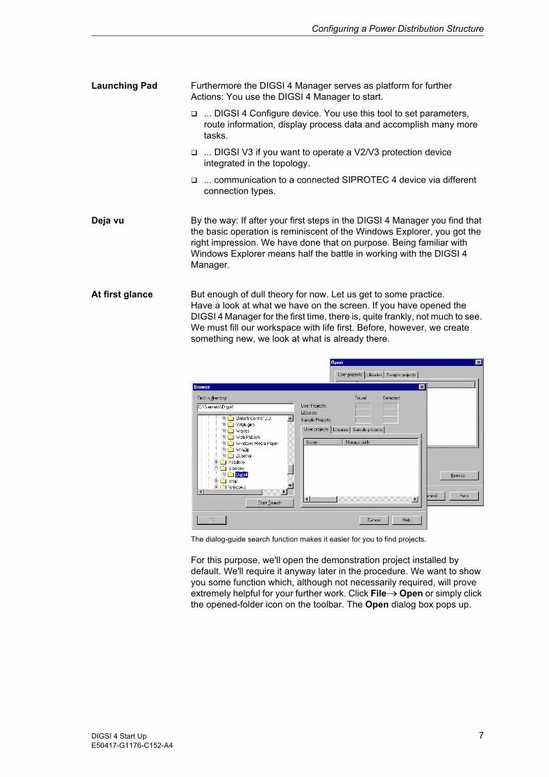
At first glance But enough of dull theory for now. Let us get to some practice. Have a look at what we have on the screen. If you have opened the DIGSI 4 Manager for the first time, there is, quite frankly, not much to see. We must fill our workspace with life first. Before, however, we create something new, we look at what is already there.
The dialog-guide search function makes it easier for you to find projects.
For this purpose, we'll open the demonstration project installed by default. We'll require it anyway later in the procedure. We want to show you some function which, although not necessarily required, will prove extremely helpful for your further work. Click File��Open or simply click the opened-folder icon on the toolbar. The Open dialog box pops up.
7DIGSI 4 Start UpE50417-G1176-C152-A4
Configuring a Power Distribution Structure
Sought, found In order to find the demo project, we will avail ourselves of the useful search function of the DIGSI 4 Manager. For this purpose, click Browse. A further dialog box pops up. Within the shown directory select the name of the folder in which you have installed DIGSI 4. Then click Find.
While the search is being executed you may have time to reflect on the meaning of the word Demo Project. Surely you do know what demo means! But what does project mean in the current context? We will go into that as soon as we have opened our demo project.
In the meantime the search has been completed successfully. As a result of the search the names of all found projects are displayed on the right half of the Find dialog box. Our sample object is named Project 1. Select this name and click OK. We now have a window for the demo project displayed on the formerly empty desktop.
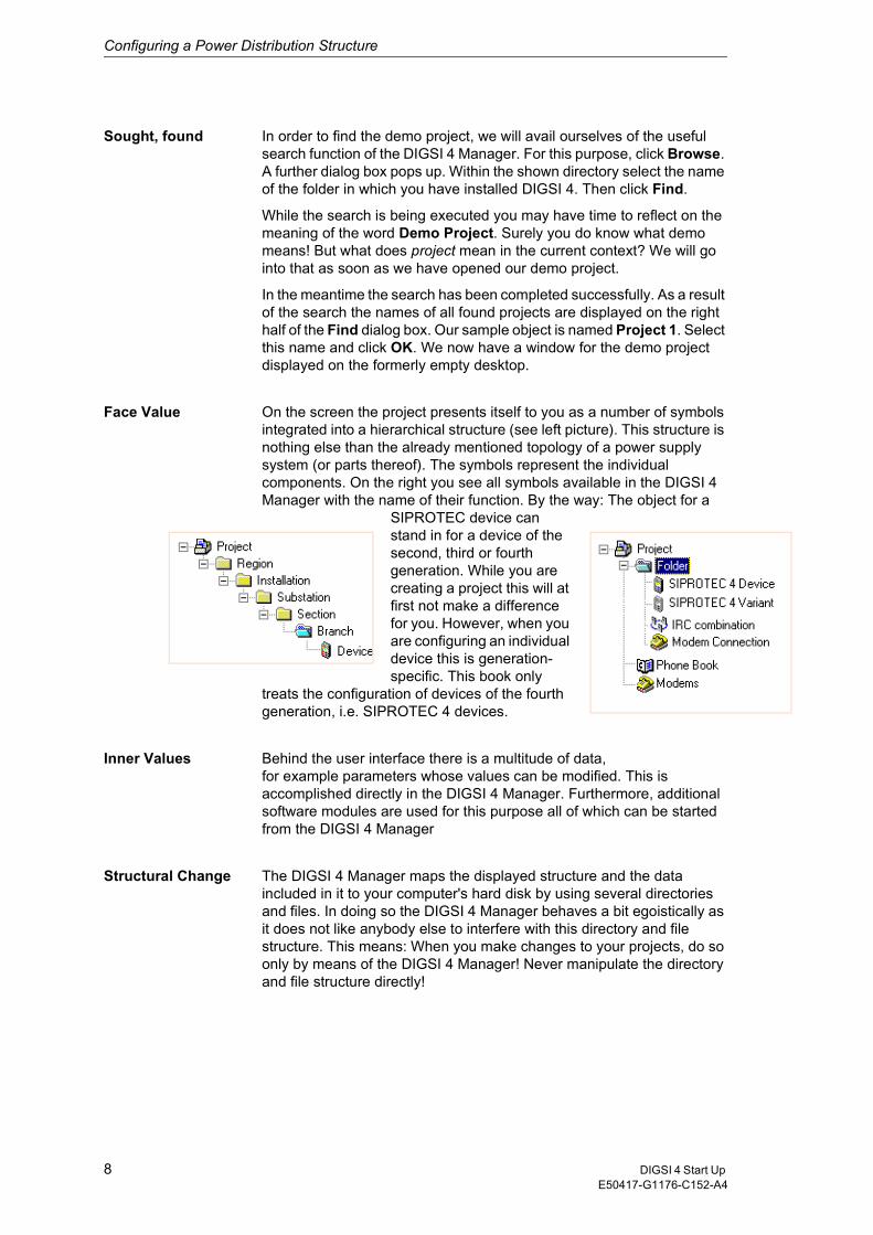
Face Value On the screen the project presents itself to you as a number of symbols integrated into a hierarchical structure (see left picture). This structure is nothing else than the already mentioned topology of a power supply system (or parts thereof). The symbols represent the individual components. On the right you see all symbols available in the DIGSI 4 Manager with the name of their function. By the way: The object for a
SIPROTEC device can stand in for a device of the second, third or fourth generation. While you are creating a project this will at first not make a difference for you. However, when you are configuring an individual device this is generation-specific. This book only
treats the configuration of devices of the fourth generation, i.e. SIPROTEC 4 devices.
Inner Values Behind the user interface there is a multitude of data,for example parameters whose values can be modified. This is accomplished directly in the DIGSI 4 Manager. Furthermore, additional software modules are used for this purpose all of which can be started from the DIGSI 4 Manager
Structural Change The DIGSI 4 Manager maps the displayed structure and the data included in it to your computer's hard disk by using several directories and files. In doing so the DIGSI 4 Manager behaves a bit egoistically as it does not like anybody else to interfere with this directory and file structure. This means: When you make changes to your projects, do so only by means of the DIGSI 4 Manager! Never manipulate the directory and file structure directly!
8 DIGSI 4 Start Up E50417-G1176-C152-A4

Configuring a Power Distribution Structure
Of Trees... But now back to the user interface. “All very well”, you will probably say, “but where is the hierarchical structure?” Click View��Show All Levels on the menu bar. Applying this command displays all existing folders as a hierarchical tree structure on the left section of the window. This section is therefore referred to as the Tree View.
The symbol system used for the tree view is overwhelmingly simple. A folder is used as symbol for all levels. The individual folders like all other symbols can be renamed individually in the DIGSI 4 Manager.
... and Lists In the tree view click now the folder Feeder 2. On the right section of the window you can see names and symbols of the objects within this folder. Since it is represented in the form of a list, the right section of the window is also referred to as the List view. You can vary the type of representation by selecting in the menu View one of the commands Large Icons, Small Icons, List or Detail or by clicking one of the corresponding toolbar buttons.
To work Following these general but necessary explanations we will now tackle the first part of our exercise. You will create a new project, add a folder to the project, and into a folder a SIPROTEC 4 device.
� Click File��New. In the New dialog box enter as project name Manhattan. If, however, you feel that you are not that deeply rooted in the East, you can of course use any other region in the US as project name. Whatever your decision, click OK afterwards. After allowing itself a brief time to reflect on this, the DIGSI 4 Manager opens a new project window.
If the DIGSI 4 Remote option package is installed on your computer, the project contains two additional symbols: Phone Book and Modems. These symbols are required for a modem connection. For more information on this topic please refer to the system manual. It contains a detailed description of the communication via a modem.
� Quite comfortably, the list view already includes a folder with the suitable name Folder. Since any further folder you insert will be named accordingly, we will exhibit some individuality in naming them. Double-click the name and change it to North Region.
� Now right-click the folder. Upon that, the context menu opens from which you select Folder. As you will have no trouble guessing, this command will create another folder within the first folder. If you want to create a folder on the same hierarchy level as the first folder, you must right-click the symbol for the project and proceed correspondingly (but that is surely old hat for you). Now give the newly added folder the name Substation 1.
� Now finally it is time to add a SIPROTEC 4 device to our topology. Now right-click the folder created most recently. Select Insert New Object ��SIPROTEC 4 device in the context menu. A small window named Device Catalog opens. You see a folder with the name "SIPROTEC 4 devices". The plus sign to the left of the symbol, however, indicates that there is more to see. And, indeed, the device catalog is structured in the same way as the tree view of the project window.
9DIGSI 4 Start UpE50417-G1176-C152-A4
Configuring a Power Distribution Structure
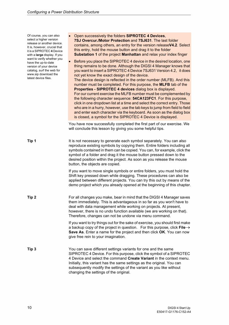
Of course, you can also select a higher version release or another device. It is, however, crucial that it is a SIPROTEC 4 Device with a large display. If you want to verify whether you have the up-to-date version of your device catalog, surf the web for www.sip download the latest device files.
� Open successively the folders SIPROTEC 4 Devices, 7SJ Overcur./Motor Protection and 7SJ631. The last folder contains, among others, an entry for the version releaseV4.2. Select this entry, hold the mouse button and drag it to the folder Substation 1 of the project Manhattan and relax your index finger
� Before you place the SIPROTEC 4 device in the desired location, one thing remains to be done. Although the DIGSI 4 Manager knows that you want to insert a SIPROTEC 4 Device 7SJ631 Version 4.2, it does not yet know the exact design of the device. The device design is reflected in the order number (MLFB). And this number must be completed. For this purpose, the MLFB tab of the Properties - SIPROTEC 4 devices dialog box is displayed. For our current exercise the MLFB number must be complemented by the following character sequence: 54CA123FC1. For this purpose, click in one dropdown list at a time and select the correct entry. Those who are in a hurry, however, use the tab keys to jump from field to field and enter each character via the keyboard. As soon as the dialog box is closed, a symbol for the SIPROTEC 4 Device is displayed.
You have now successfully completed the first part of our exercise. We will conclude this lesson by giving you some helpful tips.
Tip 1 It is not necessary to generate each symbol separately. You can also reproduce existing symbols by copying them. Entire folders including all symbols contained in them can be copied. You can, for example, click the symbol of a folder and drag it the mouse button pressed down to the desired position within the project. As soon as you release the mouse button, the objects are copied.
If you want to move single symbols or entire folders, you must hold the Shift key pressed down while dragging. These procedures can also be applied between different projects. You can try this out by means of the demo project which you already opened at the beginning of this chapter.
Tip 2 For all changes you make, bear in mind that the DIGSI 4 Manager saves them immediately. This is advantageous in so far as you won't have to deal with data management while working on projects. At present, however, there is no undo function available (we are working on that). Therefore, changes can not be undone via menu command.
If you want to try things out for the sake of exercise, you should first make a backup copy of the project in question. For this purpose, click File��
Save As. Enter a name for the project and then click OK. You can now give free rein to your imagination.
Tip 3 You can save different settings variants for one and the same SIPROTEC 4 Device. For this purpose, click the symbol of a SIPROTEC 4 Device and select the command Create Variant in the context menu. Initially, this variant has the same settings as the original. You can subsequently modify the settings of the variant as you like without changing the settings of the original.
10 DIGSI 4 Start Up E50417-G1176-C152-A4
Configuring a Power Distribution Structure
Please do not use the commands Copy and Paste to create objects which are to communicate with one and the same SIPROTEC 4 device. Applying these commands changes the device address which is necessary to unambiguously identify a device within a project. If you want to know more on this chapter, please read Chapter 8.
Tip 4 If you have configured a power distribution structure with DIGSI 3, it is possible to use this structure in DIGSI 4. Select Insert � DIGSI � Existing V3-device. You can search existing V3 structures, select the desired structure(s) and insert the structure(s) with one click into your DIGSI 4 project.
Homework The data you have created and compiled are of course not inevitably confined within the boundaries of your PC. You can save the data of an individual device to give a colleague access to them. Or you can compress the entire data of a project within one single file for archiving purposes. Try out both procedures. For exporting and importing individual devices, the context menu provides the commands Export Device and Import Device. To archive or retrieve projects select the corresponding commands in the menu File.
11DIGSI 4 Start UpE50417-G1176-C152-A4

Configuring a Power Distribution Structure
12 DIGSI 4 Start Up E50417-G1176-C152-A4
Modifying the Settings of Protection Functions4So far we have talked about integrating SIPROTEC 4 devices into a power distribution structure. The following chapter, however, will examine what goes on inside the devices. We thus address the topic of parameterisation. Strictly speaking, we treat only a part of it and that is how to set the protection functions. This is because parameterisation comprises also other topics such as allocating information, creating logic functions and editing Default Displays and Control Displays. If, however, you associate the term Parameterize intuitively with the allocation of defined values to parameters, then you know already what awaits you in this chapter.
Work... Also the second part of our serial will give you an understanding of interesting facts. You will learn:
� How to open a SIPROTEC 4 device for configuration
� How to adjust the Functional Scope of that device.
� How to change the values of individual parameters.
If you want to do only the first part of our task, you should go directly to the section on Page 15 highlighted in different background color.
... and Pleasure If you have a bit more time find the answers in this chapter to these additional questions:
� What is behind the operating modes Online and Offline?
� Is WYSIWYN a new kind of lottery?
� Are there useful parameterisation tips available?
13DIGSI 4 Start UpE50417-G1176-C152-A4
Modifying the Settings of Protection Functions
Look Under the Hood
In this chapter we want to look into a SIPROTEC 4 device to find out what is already there and what we can add, omit or modify - just as we need it. For this purpose, we imagine the device as a box which we can open to look inside. We achieve this by right-clicking the name of a SIPROTEC 4 device within a project. For our task please select the device 7SJ631 V 4.2 for this action. From the context menu select the command Open Object.
Some Hamlet
Until, however, the device opens before us, there is first the Open Device dialog box to deal with. Offline or Online, this is the question. To be able to answer this question, we must first define the meaning of these two terms. When we speak of a SIPROTEC 4 device within the scope of a project, we always means the image of a real SIPROTEC 4 device which we can also call a virtual device. This virtual device contains all data relevant for the real device. The real SIPROTEC 4 device may still sit on your desk freshly unwrapped. Though generally, it will be found somewhere within a power distribution system and thus is not immediately available to you. DIGSI 4 allows you to work exclusively with the image in the beginning and to form its functionality according to your requirements. During this procedure you are working in the operating mode Offline. All data is saved on your PC. F. you want to transfer this data into the real SIPROTEC 4 device, you must establish a communication link to this device. From that moment on you are working Online.
For the time being, we are going to work offline. Therefore, select the option Offline in the Open Device dialog box and then click OK. After some status indications, which you will simply ignore for the time being, DIGSI 4 Configure device is opened. And provide us access to everything you have always wanted to know about your SIPROTEC 4 device, but were afraid to ask.
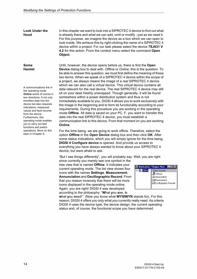
“But I see things differently”, you will probably say. Well, you are right since currently you merely see one symbol in the tree view that is named Offline. It indicates your current operating mode. The list view shows four icons with the names Settings, Measurement, Annunciation and Oscillographic Record. From that you reason incisively that there will be more icons displayed in the operating mode online. Again, you are right! DIGSI 4 was developed according to the philosophy: “What you see, is what you need!”. (Now you know what WYSIWYN stands for). For this reason, DIGSI 4 offers you only what you currently really need. As criteria DIGSI 4 uses the device type, the device design, the current operating status and, of course, the functional scope you have determined.
A communications link in the operating mode Online works of course in two directions. It not only transfers data into the device but also requests indications, measured values and fault records from the device. Furthermore, this operating mode enables you to carry out test functions and switch operations. More on this topic in Chapter 8.
14 DIGSI 4 Start Up E50417-G1176-C152-A4
Modifying the Settings of Protection Functions
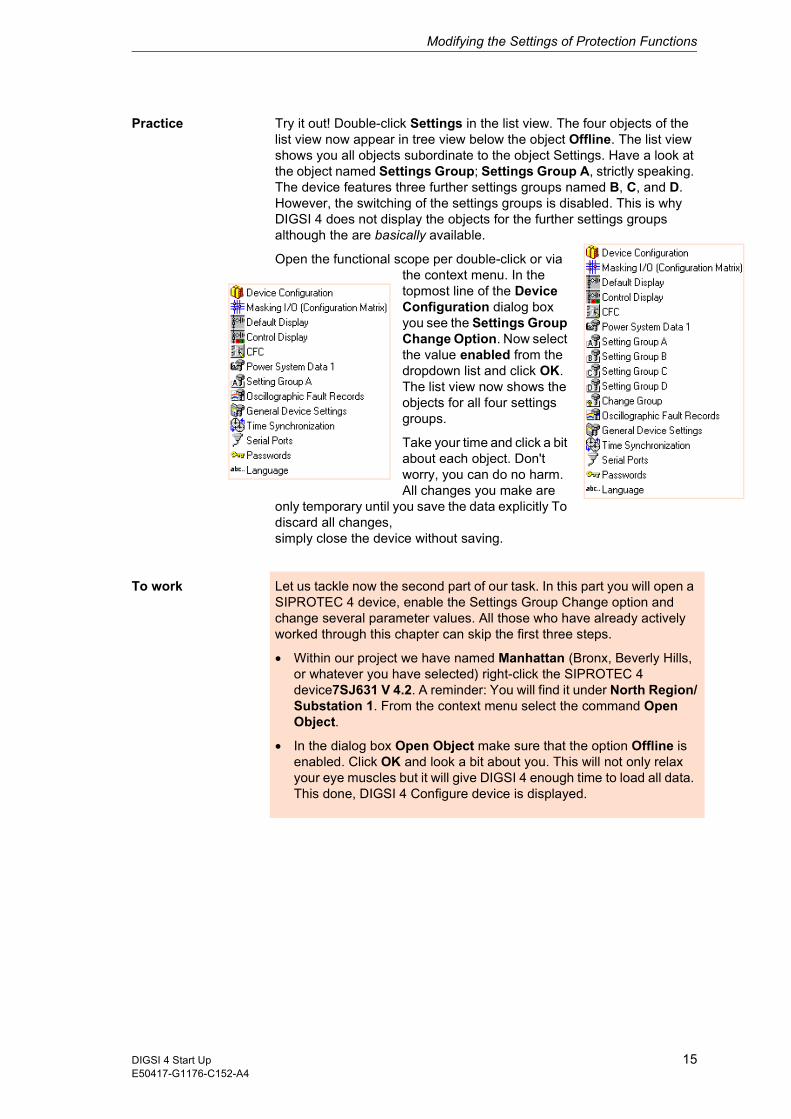
Practice Try it out! Double-click Settings in the list view. The four objects of the list view now appear in tree view below the object Offline. The list view shows you all objects subordinate to the object Settings. Have a look at the object named Settings Group; Settings Group A, strictly speaking. The device features three further settings groups named B, C, and D. However, the switching of the settings groups is disabled. This is why DIGSI 4 does not display the objects for the further settings groups although the are basically available.
Open the functional scope per double-click or via the context menu. In the topmost line of the Device Configuration dialog box you see the Settings Group Change Option. Now select the value enabled from the dropdown list and click OK. The list view now shows the objects for all four settings groups.
Take your time and click a bit about each object. Don't worry, you can do no harm. All changes you make are
only temporary until you save the data explicitly To discard all changes,simply close the device without saving.
To work Let us tackle now the second part of our task. In this part you will open a SIPROTEC 4 device, enable the Settings Group Change option and change several parameter values. All those who have already actively worked through this chapter can skip the first three steps.
� Within our project we have named Manhattan (Bronx, Beverly Hills, or whatever you have selected) right-click the SIPROTEC 4 device7SJ631 V 4.2. A reminder: You will find it under North Region/Substation 1. From the context menu select the command Open Object.
� In the dialog box Open Object make sure that the option Offline is enabled. Click OK and look a bit about you. This will not only relax your eye muscles but it will give DIGSI 4 enough time to load all data. This done, DIGSI 4 Configure device is displayed.
15DIGSI 4 Start UpE50417-G1176-C152-A4
Modifying the Settings of Protection Functions
� Double-click Settings in the list view and then Device Configuration. In the topmost line of the Device Configuration dialog box you see the Settings Group Change Option. Now select the value enabled from the dropdown list and click OK. The list view now shows objects for four settings groups.
� After you have determined that settings groups can be switched, you must indicate how the switching will be accomplished. For this purpose, double-click Settings Group Change Option. Depending on which one of the six possible values is selected, the parameter Change to another setting group allows switching of the settings groups in three different ways. You don't believe that? Then keep reading! Each settings group can be activated directly by selecting the name of the particular group as value. In doing so, four of the six possible values are already used up. Select the value via protocol if you want the switching to be performed per protocol-specific command via the system interface. The third switching type is enabled by the setting via binary input. This option may suggest that the switching can in this case only be performed via a signal at a binary input. This is, however, only one possibility. The cause of the switching can also be the pressing of a function key, an internally generated indication or the result of a logic function. Since our exercise determines that the switching of the settings group is to be accomplished due to different conditions (which we are going to link via logic functions), you must select via binary input. Subsequently, click OK.
The name suggests that there is also Power System Data 2. This is true. The Power System Data 1 apply for all settings groups. They are therefore accessible on a higher level directly in the list view. On the contrary, the Power System Data 2 can be parameterized differently for each settings group. The Power System Data 2 can only be accessed via the particular settings group.
� Now open the Power System Data 1within the list view. The dialog box Power System Data 1 contains the names of different parameters including their current values. For this purpose, the parameters are combined in several tabs. This dialog box is an example of most dialog boxes for entering parameter values. In all dialog boxes, the number and kind of the displayed parameters and tabs depend on the current operating situation. Click the tab CT's which contains parameters for the current transformer. Change the value for the parameter CT rated primary current to 1200 A and the value for the parameter CT rated secondary current to 5 A. Click the tab VT's which contains parameters for the voltage transformer Change the value for the parameter VT Rated Primary Voltage, to 12 kV and the value for the parameter VT Rated Secondary Voltage to 120 V. Click OK.
� After you have practically become a semi-professional in working with DIGSI 4, you can immediately go to the next step. If, however, you prefer a short coffee break, you should make a quick save of the changes made so far. Keep in mind: All changes you have made are only temporary until you save them explicitly. Thus click File ��Save.
16 DIGSI 4 Start Up E50417-G1176-C152-A4
Modifying the Settings of Protection Functions
Of course, also the values of settings group B must be adapted to the current situation. We have, however, decided to omit the description of that process here as it would not contribute to your understanding.
� In the Power System Data 1 dialog box the parameters were explicitly characterized as either primary or secondary parameters. Correspondingly, the values that are shown and entered are also primary or secondary values. Parameter values that are not explicitly marked can be entered and displayed either as primary or secondary values. You can select the input and display mode by clicking on the toolbar. To use primary values, click . For secondary values, however, click . In our case, please select the primary values.
� Now open Settings Group A. The Settings Group A dialog box shows all currently available functions. As you must make changes to the parameter values for the function Overcurrent double-click this entry. You should already be familiar with the dialog box 5O/5I Overcurrent Functions - Settings Group A from editing the Power System Data 1. (If not, go back to step 4, do not pass over GO, do not collect 2000 Euro.) In the tab 5O change the values of the following parameters:5O-2 pickup>>: 2500 A5O-2 Time Delay>>: 0.10 s5O-1 Pickup>: 1200 A5O-1 Time Delay>: 0.30 sClose the two dialog boxes one after the other and save the changes you have made.
Now we are done with the second part of our task. But we are not done with you. Therefore, we have another tip and homework for your self-study.
Tip If you prefer the keyboard to the mouse, you should try the following: Open the dialog box Device Configuration. Press the tab key repeatedly until the first dropdown list is selected. Use the vertical arrow buttons to move to and from between the individual lists. To open a list, hold down Alt and press one of the two vertical arrow buttons. After you have released Alt, you can select an entry within the list with the arrow buttons and confirm it by pressing Return. An even faster way is to select a dropdown list and enter the first letter ofan entry, e.g. e for enabled. The corresponding entry is selected directly.
Homework The especially industrious reader may now have a look at and edit the start characteristic of our SIPROTEC 4 device. Before you can do that, however, you must change the setting for 5O/5I Phase in the Device Configuration to user-defined pickup curve. Then open the function Overcurrent of settings group A and click the tab user-defined Ph. In the column value 1 all values are set by default to infinite. Change two or three settings in this column.
Now click characteristic. As a result, the values from the table are displayed graphically as a characteristic curve. You can now modify the characteristic by moving the break points with the mouse. When you do that you can observe how the values in the table change. Another method is to change the values in the table and see how the characteristic curve changes its shape.
17DIGSI 4 Start UpE50417-G1176-C152-A4

Modifying the Settings of Protection Functions
18 DIGSI 4 Start Up E50417-G1176-C152-A4

Allocating Information Items 5In the last chapter you have gathered experience in handling parameters. Strictly speaking, the allocation of information is a part of the parameterisation. The parameterising procedures described in this and in the following chapter, however, go far beyond the mere entering of values.
Work... We are very pleased to welcome you to the next part of our saga. We will reward you by showing you:
� how to open the device matrix,
� how to allocate information items to sources and destinations,
� how to add user-defined information items and information groups.
If you want to do only this third part of our exercise, you should go directly to the section on page 22 highlighted in different background color.
... and Pleasure The reader who thirsts for more knowledge will find in this chapter the answers to these additional questions:
� What is the device matrix capable of performing?
� How can I influence the displayed scope of information?
� Are there useful tips available on the device matrix?
19DIGSI 4 Start UpE50417-G1176-C152-A4
Allocating Information Items
On the Train As a child, did you have a model train or maybe you still have one? Then you will surely agree that switching is one of the best things about trains. One locomotive makes up a coach to be collected by a second locomotive that brings it to its final destination. When working with DIGSI 4 you can also do switching operations, however not with trains, but with information items such as metered values, measured values, indications, and commands. And instead of an extensive track system we use a clearly structured matrix.
The Matrix Now you might remember that back in your schoodays matrix calculation was not really one of your most favorite subjects. But don't worry! You won't have to calculated anything. All you have to do is allocate the mentioned information items to different sources and destinations via mouse-click. And how that works we will show you.
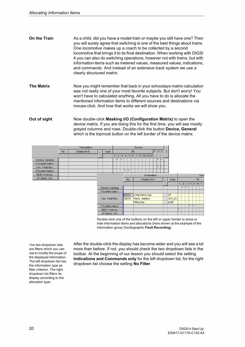
Out of sight Now double-click Masking I/O (Configuration Matrix) to open the device matrix. If you are doing this for the first time, you will see mostly grayed columns and rows. Double-click the button Device, General which is the topmost button on the left border of the device matrix.
After the double-click the display has become wider and you will see a lot more than before. If not, you should check the two dropdown lists in the toolbar. At the beginning of our lesson you should select the setting Indications and Commands only for the left dropdown list, for the right dropdown list choose the setting No Filter.
Double-click one of the buttons on the left or upper border to show or hide information items and allocations (here shown at the example of the information group Oscillographic Fault Recording).
The two dropdown lists are filters which you can use to modify the scope of the displayed information. The left dropdown list has the information type as filter criterion. The right dropdown list filters its display according to the allocation type.
20 DIGSI 4 Start Up E50417-G1176-C152-A4
Allocating Information Items
Visually, the device matrix is similar to spreadsheet programs. The information items are listed in vertical direction. Horizontally, you can find different sources and destinations. You should take a closer look at those. Move the mouse pointer slowly across the buttons on the upper bar and the cells below. Tooltips then show you in plain text what is behind the abbreviations. You will find that they are physical components on the one hand, for example binary inputs or light-emitting diodes. On the other hand, sources and destinations can also be of logic nature, CFC for example. Summed up in a few words we can put it this way: The source delivers the cause for an information item. On the contrary, the destination feels the effect of the information.
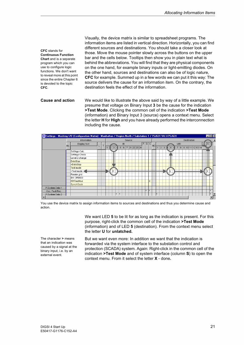
Cause and action We would like to illustrate the above said by way of a little example. We presume that voltage on Binary Input 3 be the cause for the indication >Test Mode. Clicking the common cell of the indication >Test Mode (information) and Binary Input 3 (source) opens a context menu. Select the letter H for High and you have already performed the interconnection including the cause.
You use the device matrix to assign information items to sources and destinations and thus you determine cause and action.
We want LED 5 to be lit for as long as the indication is present. For this purpose, right-click the common cell of the indication >Test Mode (information) and of LED 5 (destination). From the context menu select the letter U for unlatched.
The character > means that an indication was caused by a signal at the binary input, i.e. by an external event.
But we want even more: In addition we want that the indication is forwarded via the system interface to the substation control and protection (SCADA) system. Again: Right-click in the common cell of the indication >Test Mode and of system interface (column S) to open the context menu. From it select the letter X - done.
CFC stands for Continuous Function Chart and is a separate program which you can use to configure logic functions. We don't want to reveal more at this point since the entire Chapter 6 is devoted to the topic CFC.
21DIGSI 4 Start UpE50417-G1176-C152-A4
Allocating Information Items
All-rounder As you see the device matrix not only enables information items to be quickly allocated, what is more it provides a constant overview of all existing allocations. Take your time to get acquainted with the device matrix and also with the different options for modifying the displayed informational scope. Before you continue with our task you should restore the original state. The best way to do this is to close the device without saving your changes and then re-open it.
To work In the third part of our exercise you will allocate existing information items and those you have created yourself to sources and destinations.
� Now double-click Masking I/O (Configuration Matrix) to open the device matrix. Make sure that the settings Indications and Commands only and No Filter are enabled in the toolbar for the dropdown lists.
� Double-click the button Change Group to show the information items on the settings group switching. Following our WYSIWYN principles this button is only visible if the settings group selection was configured as available. So if you cannot change group in the device matrix, you should go back and have another look at Chapter 4.
� For as long as a settings group is active, the corresponding indication Change Group A to D is present. The trigger for that is accomplished internally by the device itself. Therefore, you cannot allocate information of the type Internal Single-Point Indication (Int SP) to any source. You can, however, allocate it to a destination.»Our exercise wants an indication to appear on the display when settings group B becomes active.«Therefore, allocate the information itemChange Group B to the Default Display as destination. You achieve that by right-clicking the common cell of the information item and of the column D. From the context menu select the letter X voilà!
� Pressing the F1 function key at the SIPROTEC 4 device is to activate the starting unit of a motor connected to the binary output BO1. It is, however, not possible to assign the function key directly to the binary output. Rather, pressing the function key generates an indication which acts upon the contact of the binary output. But as we all know indications don't grow on trees. So what can we do? The answer: We create our own so-called user-defined information.
� Click Insert ��Information on the menu bar. This action displays the information catalog. The content of this catalog is structured similarly to the device catalog of the DIGSI 4 Manager. As you already know how to handle the device catalog, the operation should not cause you any problems. Open the folder Indications and then the folder Tagging. Click the indication O/O (Int SP) and hold the mouse button down. Drag the indication to the button Change Group and release the mouse button.
� A new indication is added within the opened group. Double-click the default display text IntSP OO and change it to Motor on. Assign this new indication in the column F to Function Key 1. Thus you have determined the source. As destination select the binary output BO1 with the option U unlatched.
22 DIGSI 4 Start Up E50417-G1176-C152-A4
Allocating Information Items
� The actual starting of the motor can now take place. However, our task stipulates a switching of the settings groups. We will have a logic function perform this switching, which we are going to configure ourselves by using DIGSI 4 CFC as described in Chapter 6. To this end, we must make several information items available to DIGSI 4 CFC. One of them is the fact that the motor was started. For this purpose you must allocate the indication Motor on to CFC as the destination.
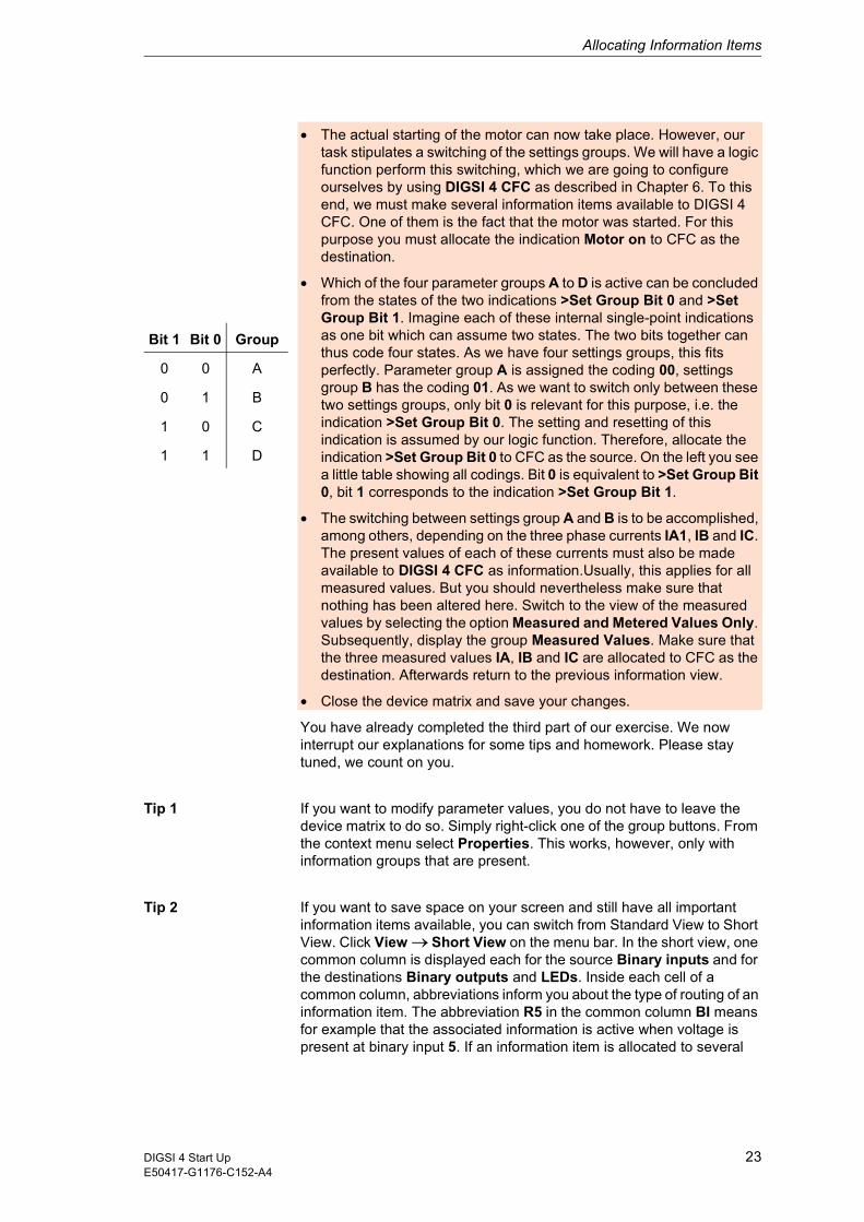
� Which of the four parameter groups A to D is active can be concluded from the states of the two indications >Set Group Bit 0 and >Set Group Bit 1. Imagine each of these internal single-point indications as one bit which can assume two states. The two bits together can thus code four states. As we have four settings groups, this fits perfectly. Parameter group A is assigned the coding 00, settings group B has the coding 01. As we want to switch only between these two settings groups, only bit 0 is relevant for this purpose, i.e. the indication >Set Group Bit 0. The setting and resetting of this indication is assumed by our logic function. Therefore, allocate the indication >Set Group Bit 0 to CFC as the source. On the left you see a little table showing all codings. Bit 0 is equivalent to >Set Group Bit 0, bit 1 corresponds to the indication >Set Group Bit 1.
� The switching between settings group A and B is to be accomplished, among others, depending on the three phase currents IA1, IB and IC. The present values of each of these currents must also be made available to DIGSI 4 CFC as information.Usually, this applies for all measured values. But you should nevertheless make sure that nothing has been altered here. Switch to the view of the measured values by selecting the option Measured and Metered Values Only. Subsequently, display the group Measured Values. Make sure that the three measured values IA, IB and IC are allocated to CFC as the destination. Afterwards return to the previous information view.
� Close the device matrix and save your changes.
You have already completed the third part of our exercise. We now interrupt our explanations for some tips and homework. Please stay tuned, we count on you.
Tip 1 If you want to modify parameter values, you do not have to leave the device matrix to do so. Simply right-click one of the group buttons. From the context menu select Properties. This works, however, only with information groups that are present.
Tip 2 If you want to save space on your screen and still have all important information items available, you can switch from Standard View to Short View. Click View ��Short View on the menu bar. In the short view, one common column is displayed each for the source Binary inputs and for the destinations Binary outputs and LEDs. Inside each cell of a common column, abbreviations inform you about the type of routing of an information item. The abbreviation R5 in the common column BI means for example that the associated information is active when voltage is present at binary input 5. If an information item is allocated to several
Bit 1 Bit 0 Group
0 0 A
0 1 B
1 0 C
1 1 D
23DIGSI 4 Start UpE50417-G1176-C152-A4

Allocating Information Items
destinations, the abbreviations of all destinations are displayed separated by commas. To view all abbreviations, double-click the cell concerned. After that, move the text cursor horizontally inside the cell.
Homework If you are interested now, you can take the following small additional task to go: Complement the allocation so that the settings group selection is signalled by two LEDs at the SIPROTEC 4 device. One LED is to be illuminated as long as the associated settings group is active.
24 DIGSI 4 Start Up E50417-G1176-C152-A4

Creating Logic Functions 6The special feature of SIPROTEC 4 devices is that they have a PLC (Programmable Logic Controller) on board. It enables you to do a lot more in addition to what you have already seen. You can
� modify existing interlocking logics or create new ones,
� create group indications,
� derive new variables from measured values and metered values,
� create alarm messages
� and many more.
You don't have to hold a degree in computers to implement the above said. Thanks to the CFC (Continuous Function Chart) method you can generate functions quickly, easily and purely graphic-oriented.
Work... Once more we will now ask you to participate as we explain:
� How to create and open a chart,
� How to add blocks from the catalog, and how to parameterize and interconnect them,
� How to compile a chart.
The reader on the fast lane can again go directly to the section on page 27 in highlighted background.
... and Pleasure However, the epicures among you who reads the chapter from A to Z will obtain answers to the following questions:
� Is there a basic procedure for configuring logic functions?
� What is the role of priority classes and run sequences?
� Are there tips available for working with DIGSI 4 CFC?
25DIGSI 4 Start UpE50417-G1176-C152-A4
Creating Logic Functions
Promised! When browsing the folder Settings you will soon come across the object named CFC. A double-click on it reveals to us that this is a folder which contains further entries. These entries are the names of so-called CFC charts. Each CFC chart contains at least one logic function which interconnects the input values with each other and, from the interconnections, derives a result. We promise you that you won't have to do any programming. Some basic knowledge of boolean algebra will suffice completely.
Crash Course The basic proceeding for creating logic functions is rather simple: First you must allocate all information items, which you need as input values or as results for your logic function, to CFC as the destination or the source in the device matrix. We have already done that in Chapter 6 and, therefore, we don't have to go into detail at this point. In the next step we add a new CFC chart and open it. Our information items are linked by means of function blocks which are found in various types in a catalog. You place them into the CFC chart via Drag & Drop, parameterize them and finally interconnect them with the input and output information items. How the blocks work in detail is not important for you to know. And, last but not least, the chart is compiled into a language that the SIPROTEC 4 device understands and it is saved together with the settings group.
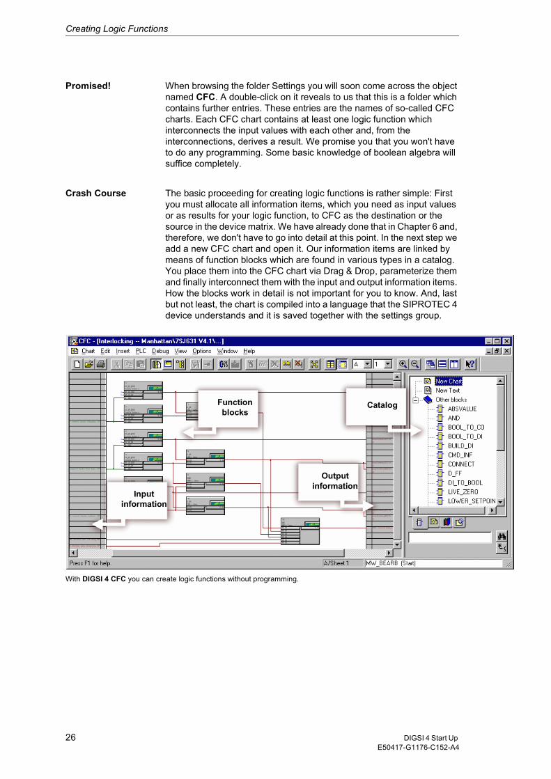
With DIGSI 4 CFC you can create logic functions without programming.
Input information
Output information
CatalogFunction blocks
26 DIGSI 4 Start Up E50417-G1176-C152-A4
Creating Logic Functions
Building Plans... Before we are putting the above said into practice, we will illustrate it by example of an existing CFC chart. Double-click the chart name Interlocking. DIGSI 4 CFC is opened and the selected chart is loaded. What you now see before you is not some abstract design pattern but the graphic representation of a logic function. Have a look at the status bar and you will find A/Sheet 1 written there. This is because every chart can consist of several partial charts with each partial chart comprising up to six sheets What you see now is sheet 1 of the partial chart A.
...... and Building Blocks
In the center of the sheet there are several rectangles. They are the already mentioned function blocks. Each function block has a number of inputs to its left side which can partly be parameterized. On its right side you can see the outputs. The inputs and outputs of the function blocks are connected visually via lines that symbolize the logic interconnection of signals. You will find all available function blocks within a catalog on the right border of DIGSI 4 CFC.
Need for Information
What is still missing now are the information items you have allocated in the device matrix. Move the horizontal scroll bar so that the left section of the sheet is displayed. Here you can see the information items which you have allocated to CFC as the destination in the device matrix. They serve as input information for the logic function. By the way, you will not necessarily see all allocated information items but only those that were already interconnected with function blocks. A glance at the right side of the sheet shows us the output information items which are generated as the result of a logic function. These information items must be allocated to CFC as the source in the device matrix. Now close the chart and go ahead to the next part of the exercise, i.e. Logic functions.
To workfirst part
During this part you will add function blocks to a new chart, parameterize them and interconnect them. Afterwards, you will have the plan compiled.
� In the list view of DIGSI 4 Configure device select the object CFC. Click Insert ��CFC chart on the menu bar. This command opens an empty CFC chart. In this chart you will create a logic function which is to generate an indication as soon as all currents at the same time are smaller than 5% of their nominal value. Therefore, change the name of the chart into limit value currents. To keep things from becoming to easy, you cannot just rename the object directly. Rather, you must open the dialog box Object Properties via the context menu and rename the object there.
� To open the chart you must double-click the chart name. At first you will see an immaculately white screen before you that virtually invites you to do some experimenting. On the right section of DIGSI 4 CFC you should see the catalog with the function blocks. If not, click View��Catalog on the menu bar. Within the catalog double-click Other Blocks, select the block named Lower_Setpoint, hold the mouse button down and drag it onto the sheet. Place it approximately in the left upper corner of the sheet and release the mouse button. (Where you place the block is of course only relevant for the overview of the entire
27DIGSI 4 Start UpE50417-G1176-C152-A4

Creating Logic Functions
chart but not, however, for the function).
� The added function block Lower_Setpoint compares a value applied at its input to a parameterized limit value and delivers the result TRUE at the output for as long as the value remains below the limit. To determine the limit value double-click the connection Limit of the function block. In the dialog box Properties - Connection you see the input box Value. Enter 5 here and click OK. After you have closed the dialog box you will see the effect of your action: The value 5 is displayed at the connection Limit.
� For you to get the knack of this procedures, repeat them twice. Therefore, once again: Insert the function block Lower_Setpoint and set the limit value to 5.
� The second input of each function block must now be interconnected with one of the three currents. Therefore again right-click the topmost block but this time the connection Val below the connection Limit. Click Interconnection to address and thereby open the dialog box Select Left Border. Select the measured value IA and click OK. The entry for the interconnected information now appears on the left border. The actual interconnection is visualized by a connecting line between the information and the input of the function block. Now interconnect the two other function blocks with the currents IB and IC.
� According to our exercise an indication is to be generated only when all three currents at the same time go beyond the limit value. We therefore rummage through our knowledges in boolean algebra and come to the conclusion that we will interconnect the outputs of the three existing function blocks with an AND block. This block will deliver the information TRUE exactly when TRUE also applies at all inputs simultaneously. Thus, as already practiced, drag a function block of the type AND from the catalog onto the sheet.
� When you look closely at the block, you will notice that one entry is missing. This should not bother us any further since the number of entries is a modifiable property of the function block. Right-click the block and you will find the corresponding command in the context menu, i.e. Number of I/Os. Increase the number of I/Os to 3.
If you feel that the title of the dialog box is a little bit strange, please remember the following: Information items which were allocated to CFC as the destination in the device matrix are now available to you as input information. Interconnected input information items are displayed on the left border. The currently opened dialog box offers you all information items available for the left border.
28 DIGSI 4 Start Up E50417-G1176-C152-A4
Creating Logic Functions
� Interconnecting the individual function blocks with each other is the easiest part now. First click the output of a function block of the type Lower_Setpoint and subsequently click the input of the AND function block. The interconnection is shown by a connecting line.
� As another thing we need an unambiguous result of our logic function. For this purpose we must interconnect the output of the AND block with an indication. It is to be transmitted as result of the first logic function as soon as our conditions are fulfilled At the same time, it will then serve as input information for the second logic function, which we must yet configure. So far, we have not prepared such an indication, but we will do that now.
� Without closing DIGSI 4 CFC go to DIGSI 4 Configure device. Open the device matrix. This time we are going to insert the required indication into a group which we have created ourselves previously. The new group is to be placed directly below the group Change Group. Right-click the button Change Group. In the context menu click Insert Group - After. In the Insert Group dialog box enter Min Current as short text. You can also change the long text as you like. Click OK.
� Create a new indication as we did previously in Chapter 5. Use the type IntSP(OC) from the folder Tagging. Change the display text of this indication to I<5% and allocate it to CFC as source and destination.
� Save your changes and close the device matrix. Afterwards go back to DIGSI 4 CFC.
� Right-click the output of the AND function block. In the context menu click Interconnection to address. The dialog box that opens is quite suitably named Select right border. Here select the indication I<5% and click OK. The desired interconnection is displayed.
� You have now completed your first logic function. However, it is still in a form that the SIPROTEC 4 device does not understand. You must translate it into language suitable for the device. Strictly speaking, you only have to give the command for this action and DIGSI 4 CFC does the rest. Click File��Compile ��Charts as program on the menu bar. DIGSI 4 CFC now generates an executable code from all existing charts which is uploaded into the SIPROTEC 4 device together with the settings group.
� When the compiling process is finished close DIGSI 4 CFC and save your work in DIGSI 4 Configure device.
29DIGSI 4 Start UpE50417-G1176-C152-A4

Creating Logic Functions
SSM or SMS? Those readers who only care for the highlighted sections of our exercise should now wait before immediately leafing through to the next chapter, since our exercise is continued below. First, however, we want to relate the above said to our famous SSM, that is the seven-steps-method.
1. Make all allocations in the device matrix required for each new logic function. Often, you will have to add new internal single-point indications (flags) for this purpose. When all allocations are done, save your changes.
2. Insert a new CFC chart, name it as you like and open it.
3. Before you insert the first block you must first verify the priority class. You may have to select a different priority class if necessary. (Please do not flip back through the pages now to find out where exactly you have overlooked this piece of information as our explanations on this topic will be given following our SSM.)
4. Insert the blocks into the CFC chart, parameterize them and interconnect them with each other.
5. Launch the compilation run. Possible messages displayed at the end of the compiling process will indicate errors in the CFC chart. he most common causes are different tasks within a chart and also a wrong run sequences (see also below).
6. Close DIGSI 4 CFC and save your entries in DIGSI 4 Configure device.
7. Transfer the parameter set into the SIPROTEC 4 device to activate the generated logic functions there.
Priority run And now to the topics priority class and run sequence. We will, however, present only the most important facts. We will, however, present only the most important facts. For detailed information, please refer to the manual and the help for DIGSI 4 CFC.
The reason for processing logic function in different priority classes is primarily a technical one: To use the processor capacity of the SIPROTEC 4 device to its maximum capacities. Therefore, the individual priority classes differ in their way of processing the tasks they have been assigned. Firstly, tasks are processed with different priorities, irrespective of their priority class. Secondly, the cause for the processing may be cyclic or event-driven. Basically, there are four priority classes available. Within a chart you must, however, select exactly one of them.
Equally important is the run sequence. It determines the order in which the individual blocks are processed. In this context, please remember the following rule: A block whose output is connected to the input of another block must be processed before this second block.
You can conclude the processing sequence from the so-called sequence number in the green box of a block. (The priority class is also indicated here). The run sequence is determined by the order in which the individual function blocks were inserted. To display or modify the run
30 DIGSI 4 Start Up E50417-G1176-C152-A4
Creating Logic Functions
sequence, click Edit��Run Sequence on the menu bar. The already well-known tree structure now shows us the current order of the function blocks. You can change them via Drag & Drop.
To work,second part
Let us go back to our exercise. The first logic function, which we have already configured, compares the currents with a limit values and generates a user-defined indication if they fall below this value. This indication is transmitted to a second logic function which interprets it as a criterion for switching.
� You already know the following steps: insert a CFC chart, rename it, open the chart. The second logic function triggers the actual switching of the settings group. Therefore, name the CFC chart for example Change Group.
� When DIGSI 4 CFC has opened the chart, have a look at the status bar on the right bottom. Here you can see which priority class is currently set. At present this should be class MW_BEARB which was required for the first logic function. We must now set it to PLC1.
� Click Edit ��Run sequence on the menu bar. The window is now split into a tree and a list view. n the tree view select the priority class PLC1_BEARB. Then click Edit��Predecessor for installation. If all works correctly, you will receive a message confirming your change.
� Close the message box and verify again the display on the status bar. PLC1_BEARB is now displayed as priority class. The installation Start means that no function block has yet been integrated in this priority class. Now you only have to get back to the sheet view. To accomplish that select the menu item Edit��Run Sequence a second time.
� Following these restructuring measures, let us begin with the configuration of the second logic function. We remember: One criterion for switching the parameter group is the expiration of 10 seconds following the motor start. We have this period signalled to us by means of a timer which we start together with the motor. Therefore, drag a function block of the type Timer from the catalog onto the sheet.
� Right-click the start input BO S of the timer and select interconnection to address from the context menu. Here select the indication Motor On and click OK. When the motor is started, exactly this indication is output which then serves as the starting criterion for the timer.
� Now you must set the timer. For this purpose, open the object properties dialog for the connection T1 of the timers. Into the box Value enter 10000. Subsequently click OK.
� The second criterion for switching the settings group is the indication I<5%, which is transmitted when the result of our first logic function is TRUE. Since only one of the two criteria must be fulfilled for switching the parameter group, we interconnect both result with a function block of the type OR. Drag such a function block onto the sheet.
31DIGSI 4 Start UpE50417-G1176-C152-A4
Creating Logic Functions
� Connect the output Q T1 of the timer to one of the two inputs of the OR block. If you don't remember how to do that, re-read the first paragraph. Interconnect the second input of the OR block with the indication I<5%.
� For the parameter group switching to take place, the internal single-point indication >Set Group Bit 0 must assume the value 1, i.e. must be true. Therefore, interconnect the output of the OR block with exactly that indication and our logic function is completely configured.
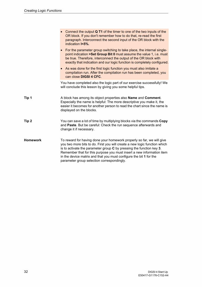
� As was done for the first logic function you must also imitate a compilation run. After the compilation run has been completed, you can close DIGSI 4 CFC.
You have completed also the logic part of our exercise successfully! We will conclude this lesson by giving you some helpful tips.
Tip 1 A block has among its object properties also Name and Comment. Especially the name is helpful: The more descriptive you make it, the easier it becomes for another person to read the chart since the name is displayed on the blocks.
Tip 2 You can save a lot of time by multiplying blocks via the commands Copy and Paste. But be careful: Check the run sequence afterwards and change it if necessary.
Homework To reward for having done your homework properly so far, we will give you two more bits to do. First you will create a new logic function which is to activate the parameter group C by pressing the function key 3. Remember that for this purpose you must insert a new information item in the device matrix and that you must configure the bit 1 for the parameter group selection correspondingly.
32 DIGSI 4 Start Up E50417-G1176-C152-A4

Creating Logic Functions
If you have still some energy left, make an LED of your choice flash. The flashing is started by means of the function key 3, and it is stopped with function key 4. If that is not difficult enough for you, use only one function key for switching on and off.
By the way: You can find this and further examples in our manual for DIGSI 4 CFC, including solutions.
33DIGSI 4 Start UpE50417-G1176-C152-A4

Creating Logic Functions
34 DIGSI 4 Start Up E50417-G1176-C152-A4
Editing Default and Control Displays 7A picture says more than thousand words. This could be the reason for our keeping this chapter very brief. Another reason could be the salary of the author. The true and only reason is, however, the really easy operation of the DIGSI 4 Display Editor which enables us to finish our exercise in a very short time.
Work... This chapter, too, contains a compulsory part where we will explain:
� How to load the Default Display into the DIGSI 4 Display Editor for editing,
� How to insert a text object into the Default Display,
� How to implement the display of the active settings group in the Default Display.
If you are only interested in our exercise, you can go directly to the highlighted section on page 38.
... and Pleasure The reader who want to score additional points by reading the whole chapter will get answers to the following questions:
� What is a Default Display and what is Control Display?
� How is the DIGSI 4 Display Editorstructured?
� Are there useful tips available for DIGSI 4 Display Editor?
35DIGSI 4 Start UpE50417-G1176-C152-A4
Editing Default and Control Displays
Works of the21st century
Default and Control Displays are illustrations that can be shown on the display of your SIPROTEC 4 device, provided, of course, you have invested in a SIPROTEC 4 device with a large display.
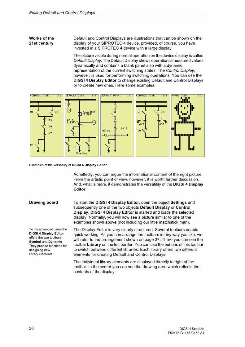
The picture visible during normal operation on the device display is called Default Display. The Default Display shows operational measured values dynamically and contains a blank panel also with a dynamic representation of the current switching states. The Control Display, however, is used for performing switching operations. You can use the DIGSI 4 Display Editor to change existing Default and Control Displays or to create new ones. Here some examples:
Examples of the versatility of DIGSI 4 Display Editor.
Admittedly, you can argue the informational content of the right picture. From the artistic point of view, however, it is worth further discussion. And, what is more, it demonstrates the versatility of the DIGSI 4 Display Editor.
Drawing board To start the DIGSI 4 Display Editor, open the object Settings and subsequently one of the two objects Default Display or Control Display. DIGSI 4 Display Editor is started and loads the selected display. Normally, you will now see a picture similar to one of the examples shown above (not including our little matchstick man).
To the advanced users the DIGSI 4 Display Editor offers the two toolbars Symbol and Dynamic They provide functions for designing new library elements.
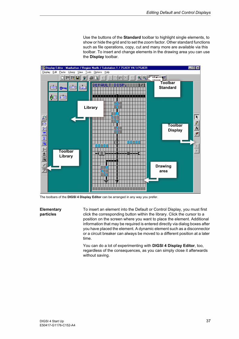
The Display Editor is very clearly structured. Several toolbars enable quick working. As you can arrange the toolbars in any way you like, we will refer to the arrangement shown on page 37. There you can see the toolbar Library on the left border. You can use the buttons of this toolbar to switch between different libraries. Each library offers two different elements for creating Default and Control Displays.
The individual library elements are displayed directly to right of the toolbar. In the center you can see the drawing area which reflects the contents of the display.
36 DIGSI 4 Start Up E50417-G1176-C152-A4
Editing Default and Control Displays
Use the buttons of the Standard toolbar to highlight single elements, to show or hide the grid and to set the zoom factor. Other standard functions such as file operations, copy, cut and many more are available via this toolbar. To insert and change elements in the drawing area you can use the Display toolbar.
The toolbars of the DIGSI 4 Display Editor can be arranged in any way you prefer.
Elementary particles
To insert an element into the Default or Control Display, you must first click the corresponding button within the library. Click the cursor to a position on the screen where you want to place the element. Additional information that may be required is entered directly via dialog boxes after you have placed the element. A dynamic element such as a disconnector or a circuit breaker can always be moved to a different position at a later time.
You can do a lot of experimenting with DIGSI 4 Display Editor, too, regardless of the consequences, as you can simply close it afterwards without saving.
Library
ToolbarLibrary
ToolbarStandard
ToolbarDisplay
Drawing area
37DIGSI 4 Start UpE50417-G1176-C152-A4
Editing Default and Control Displays
To work To all those who are joining us at this point: Welcome to the last part of our task. During this part of the exercise you will open the DIGSI 4 Display Editor, insert a text object and interconnect it with the active settings group.
� Open the object Settings and subsequently the object Default Display. In doing so, the Display Editor is started and the Default Display is loaded.
� Click the button in the Library toolbar. The library Value Display is opened. If you don't see the required toolbar anymore, click View��
Toolbars. You can determine in the following dialog what toolbars are to be displayed. Within the displayed library click the symbol A Text. If you move the mouse cursor on the display shown it turns into a pencil.
� Click on any position within the display. The dialog box Link opens. This dialog box shows the display texts of all information items which are allocated to the Default Display as the destination in the device matrix. Each state of one of these information items could now be used as criterion for displaying a user-defined text. Our text is to be displayed when the settings group B is active. Therefore, select the indication Group B and then click OK.
� Now finally we have the opportunity of proving our skills as a writer and must formulate a concise text. Although it seems unpretentious at first glance, our proposal is unbeatable in terms of clarity and easy understanding: Active. Should our proposal convince you, enter the five letters and then click the green checkmark.
� At the present time, you would obtain as display of the active settings group only a two-digit bit pattern. Since this is of not much use for us, we will change it. Click the arrow icon on the toolbar Display. Now double-click the displayed value or select the command Object Properties from its context menu. In the dialog box Object Properties - User Text enter the letter A for the value 01, for the value 10 enter the letter B. Close the dialog box
� To conclude your creative activities move the text and the associated letter to an appropriate position within the display by means of drag and drop.
� Click View��Normal Size and the Default Display embedded in a SIPROTEC 4 device is displayed. You like the outcome? In this case you should save it and afterwards close DIGSI 4 Display Editor without reservations.
You have completed also the logic part of our exercise successfully! However, this does not mean that we have reached the end of the book.
38 DIGSI 4 Start Up E50417-G1176-C152-A4
Editing Default and Control Displays
Must-Reading The next chapter should be must-reading for everybody. And Chapter 8 is rewarding at any rate for all anybody who already has SIGRA 4 or would like to have it. We conclude this chapter with some tips and homework.
Tip 1 If you have started the DIGSI 4 Display Editor for example with the Default Display, you do not have to start it again to open the Control Display. In the menu Display you will find commands which you can use to open one of the two displays independently of each other.
Tip 2 If you are rather a fan of painting by numbers, then open one of the existing templates via Display ��Template��Open. Maybe you can use these templates to implement your specific requirements more quickly.
Homework For all untiring readers we have two more little exercises. Exercise number one: Integrate a text or graphical indications into the display which indicates that the key switch is set to Local and not to Remote. Exercise number two: Expand exercise 1 so that this information flashes. For this purpose you must fall back on DIGSI 4 CFC (see Homework in Chapter 6).
39DIGSI 4 Start UpE50417-G1176-C152-A4

Editing Default and Control Displays
40 DIGSI 4 Start Up E50417-G1176-C152-A4
Working online 8
So far we have worked in the operating mode Offline. Everything we have accomplished within the scope of the exercise was saved to files and is now stored somewhere on our PC. What we must do now is transfer this data into the SIPROTEC 4 device. We will also receive information from the device. For this purpose we will go online by establishing a communication link between the PC and the SIPROTEC 4 device. You will see in the following that this operating mode makes a lot more possible.
Must Reading We recommend to read this chapter completely as it contains essential information for working in the operating mode Online. The following pages will tell you:
� What measures are necessary for correctly establishing a connection
� How to change parameter values online.
� How to read process data from the device.
� What test functions are available.
� How to trigger a test fault record.
The number you have dialed isnot available?
We had selected a 7SJ63 as demo device for the exercise. Since, however, the SIPROTEC 4 family includes several other devices, it is quite likely that exactly this device in the design described is currently not in your possession. But in the end, this does not matter as long as you do not intend to try out our implemented motor control and supervision in reality.
DANGER!
Please observe that operational equipment connected to the binary outputs such as circuit breakers or disconnector switches can be switched in the operating mode Online. Those carrying out operator actions must be suitably qualified and have a good knowledge of system conditions. Improper handling can cause death as well as serious injury or damage to property. Therefore, for test and training purposes use a device that is not connected with the system.
41DIGSI 4 Start UpE50417-G1176-C152-A4
Working online
It is important that the type and the design of the virtual device in DIGSI 4 and of the real device are identical. Otherwise an error message is bound to come up while the connection is established. Therefore, the best idea is to insert a new SIPROTEC 4 device into your project of the same type as the real device. During this process enter the order number (MLFB) of the device and, thereby, determine the version in DIGSI 4. You will find the MLFB on top of the SIPROTEC 4 device.
Contact Before we can establish a logic connection to our SIPROTEC 4 device, we must first set up a physical connection. This means that we will connect the PC, on which DIGSI 4 is installed, to a SIPROTEC 4 device via a cable. You'll notice that a suitable cable is already included with your copy of DIGSI 4. Plug this cable into the serial port of your PC and into the port on the front panel of the SIPROTEC 4 device. Subsequently, connect the SIPROTEC 4 device to the proper voltage supply. Before you do this, you should read the device documentation to avoid damaging your S 4 device. That done, turn on the voltage supply. The SIPROTEC 4 device is now in the startup phase. It is finished when the Default Display appears on the display of the device. And to us it signals that we can get started.
(S)election day To open a SIPROTEC 4 device in the operating mode Online, you must proceed in the same way as you are used from the operating mode Offline: double-click the symbol of the device in the DIGSI 4 Manager or select the command Open Object from the context menu. Only when you are in the dialog box Open Device will you decide in what operating mode to open the SIPROTEC 4 device. Among the different options, you select the one that is equivalent to the real physical connection between the computer and the SIPROTEC 4 device In our case this is the option Online via DIGSI. Admittedly, this designation does not quite fit, but we what we mean is a direct, serial connection between the PC and the SIPROTEC 4 device. For this kind of connection DIGSI 4 requires additional information. We use the two dropdown lists to tell DIGSI 4 what port is used by each of two parties. From the dropdown list PC interface select the name of the serial port into which you have plugged the cable From the dropdown list Device interface select front.
Now you can do what you have been longing for all this time: Click OK. A little animation makes the waiting until the connection is established worthwhile. After having drunk as much as half a cup of coffee you will probably think that something is wrong and you may feel inclined to click Cancel. Please wait a little longer until you are rewarded for you patience with the following message:
42 DIGSI 4 Start Up E50417-G1176-C152-A4
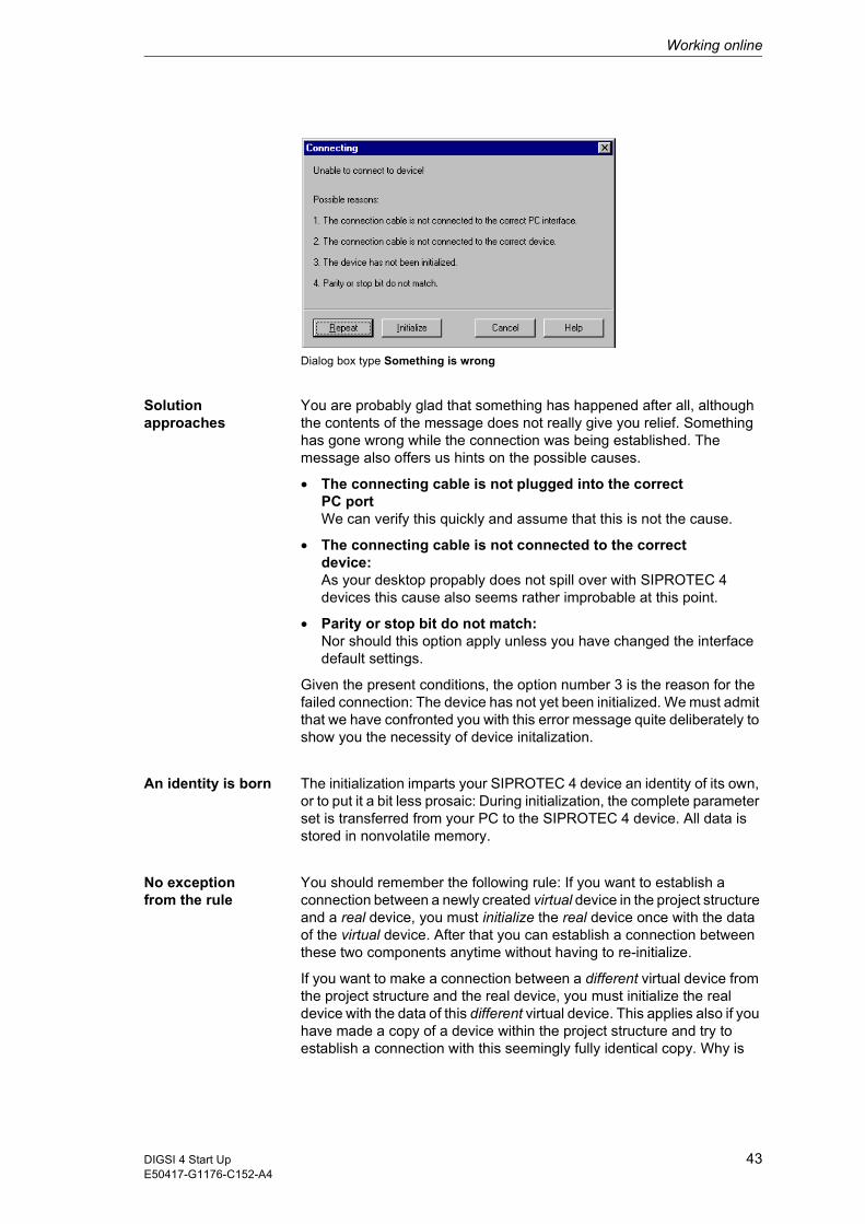
Working online
Dialog box type Something is wrong
Solution approaches
You are probably glad that something has happened after all, although the contents of the message does not really give you relief. Something has gone wrong while the connection was being established. The message also offers us hints on the possible causes.
� The connecting cable is not plugged into the correct PC portWe can verify this quickly and assume that this is not the cause.
� The connecting cable is not connected to the correctdevice:As your desktop propably does not spill over with SIPROTEC 4 devices this cause also seems rather improbable at this point.
� Parity or stop bit do not match:Nor should this option apply unless you have changed the interface default settings.
Given the present conditions, the option number 3 is the reason for the failed connection: The device has not yet been initialized. We must admit that we have confronted you with this error message quite deliberately to show you the necessity of device initalization.
An identity is born The initialization imparts your SIPROTEC 4 device an identity of its own, or to put it a bit less prosaic: During initialization, the complete parameter set is transferred from your PC to the SIPROTEC 4 device. All data is stored in nonvolatile memory.
No exception from the rule
You should remember the following rule: If you want to establish a connection between a newly created virtual device in the project structure and a real device, you must initialize the real device once with the data of the virtual device. After that you can establish a connection between these two components anytime without having to re-initialize.
If you want to make a connection between a different virtual device from the project structure and the real device, you must initialize the real device with the data of this different virtual device. This applies also if you have made a copy of a device within the project structure and try to establish a connection with this seemingly fully identical copy. Why is
43DIGSI 4 Start UpE50417-G1176-C152-A4
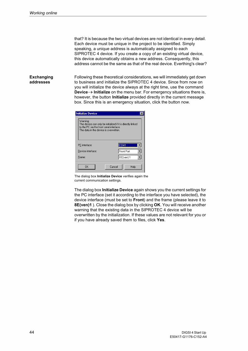
Working online
that? It is because the two virtual devices are not identical in every detail. Each device must be unique in the project to be identified. Simply speaking, a unique address is automatically assigned to each SIPROTEC 4 device. If you create a copy of an existing virtual device, this device automatically obtains a new address. Consequently, this address cannot be the same as that of the real device. Everthing's clear?
Exchangingaddresses
Following these theoretical considerations, we will immediately get down to business and initialize the SIPROTEC 4 device. Since from now on you will initialize the device always at the right time, use the command Device��Initialize on the menu bar. For emergency situations there is, however, the button Initialize provided directly in the current message box. Since this is an emergency situation, click the button now.
The dialog box Initialize Device verifies again the current communication settings.
The dialog box Initialize Device again shows you the current settings for the PC interface (set it according to the interface you have selected), the device interface (must be set to Front) and the frame (please leave it to 8E(ven)1 ). Close the dialog box by clicking OK. You will receive another warning that the existing data in the SIPROTEC 4 device will be overwritten by the initialization. If these values are not relevant for you or if you have already saved them to files, click Yes.
44 DIGSI 4 Start Up E50417-G1176-C152-A4
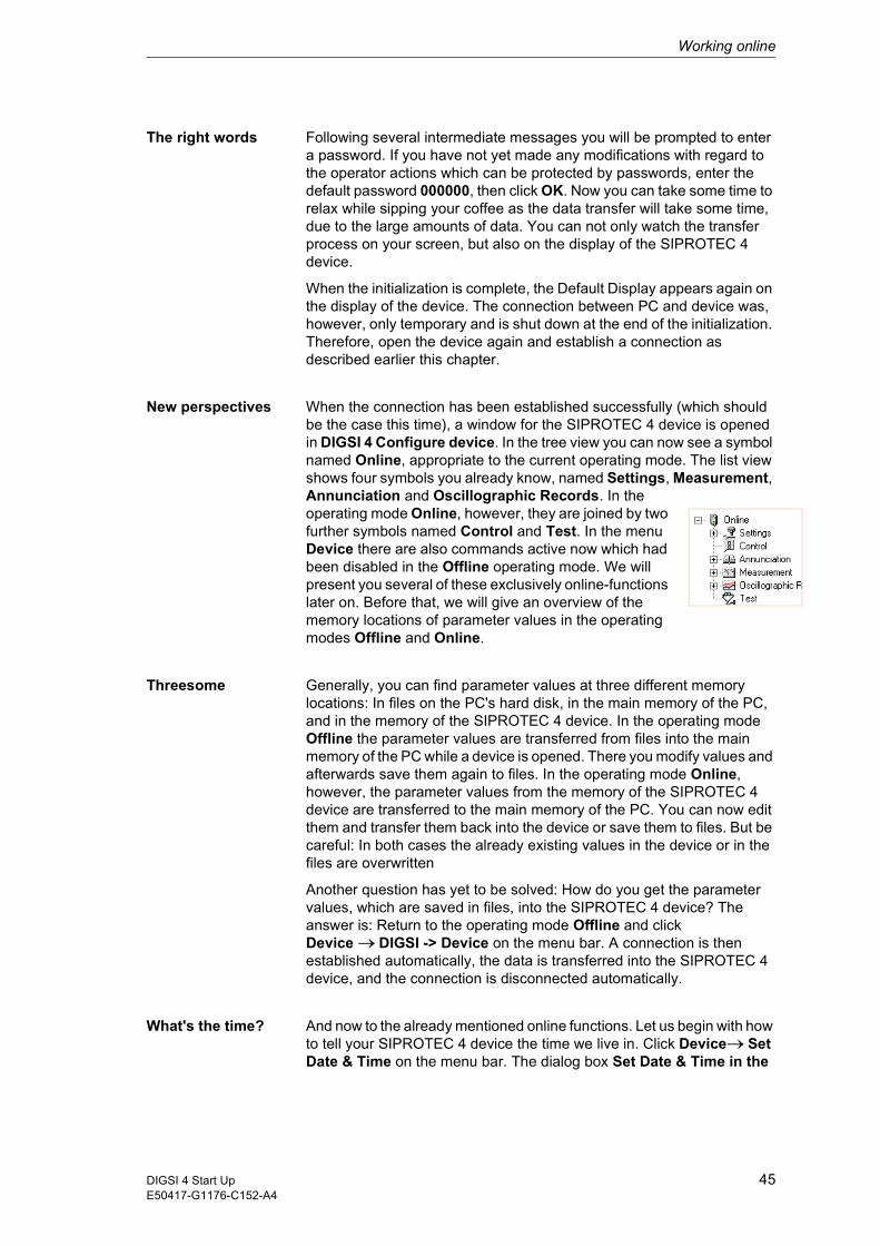
Working online
The right words Following several intermediate messages you will be prompted to enter a password. If you have not yet made any modifications with regard to the operator actions which can be protected by passwords, enter the default password 000000, then click OK. Now you can take some time to relax while sipping your coffee as the data transfer will take some time, due to the large amounts of data. You can not only watch the transfer process on your screen, but also on the display of the SIPROTEC 4 device.
When the initialization is complete, the Default Display appears again on the display of the device. The connection between PC and device was, however, only temporary and is shut down at the end of the initialization. Therefore, open the device again and establish a connection as described earlier this chapter.
New perspectives When the connection has been established successfully (which should be the case this time), a window for the SIPROTEC 4 device is opened in DIGSI 4 Configure device. In the tree view you can now see a symbol named Online, appropriate to the current operating mode. The list view shows four symbols you already know, named Settings, Measurement, Annunciation and Oscillographic Records. In the operating mode Online, however, they are joined by two further symbols named Control and Test. In the menu Device there are also commands active now which had been disabled in the Offline operating mode. We will present you several of these exclusively online-functions later on. Before that, we will give an overview of the memory locations of parameter values in the operating modes Offline and Online.
Threesome Generally, you can find parameter values at three different memory locations: In files on the PC's hard disk, in the main memory of the PC, and in the memory of the SIPROTEC 4 device. In the operating mode Offline the parameter values are transferred from files into the main memory of the PC while a device is opened. There you modify values and afterwards save them again to files. In the operating mode Online, however, the parameter values from the memory of the SIPROTEC 4 device are transferred to the main memory of the PC. You can now edit them and transfer them back into the device or save them to files. But be careful: In both cases the already existing values in the device or in the files are overwritten
Another question has yet to be solved: How do you get the parameter values, which are saved in files, into the SIPROTEC 4 device? The answer is: Return to the operating mode Offline and click Device � DIGSI -> Device on the menu bar. A connection is then established automatically, the data is transferred into the SIPROTEC 4 device, and the connection is disconnected automatically.
What's the time? And now to the already mentioned online functions. Let us begin with how to tell your SIPROTEC 4 device the time we live in. Click Device��Set Date & Time on the menu bar. The dialog box Set Date & Time in the
45DIGSI 4 Start UpE50417-G1176-C152-A4

Working online
Device generally offers you two options for achieving your objective: Either you take the easy way and take over date and time of the PC; or you are an individualist and set both values manually. Since DIGSI 4 also wants some say in this matter, it does not allow you to set the weekday as you like. It is calculated automatically from the entered date. Whichever way you choose, PC or manually, click OK to transfer the time setting into the SIPROTEC 4. To check whether the device has really received the time setting, press the button MENU on the SIPROTEC 4 device and go via Settings � Setup/Extras � Date/Time to the display of date and time. Here you can study the result of your work.
Goal-oriented Let us now get from the menu to the operating tree. Double-click Setting. We want to show you how you can change individual parameter settings selectively in the SIPROTEC 4 device. For this purpose open the Settings group A and subsequently the function Overcurrent 50/51, for example. Change the value of any parameter. If you now closed the dialog box by clicking OK, the modified setting would be saved temporarily. However, this would not yet have any consequences on the corresponding setting in the device. We want, however, to transfer the modified setting immediately into the device. Therefore, click DIGSI -> Device. In the following password prompting use again the default password 000000, unless you have already changed it. Click OK and things take their course.
Comparison The parameter setting was only changed in the device. The setting in the parameter set, saved on your hard disk for this device, was not changed. This happens only when you explicitly save the changed settings. To avoid that you lose track of things after having made several changes, DIGSI 4 features a compare function. You can use it to compare the settings in the device parameter set with the file parameter set. Click Edit�Compare Parameters. In the dialog box that display click Deselect All and thus reduce the scope of the comparison initially to zero. Afterwards select Settings Group A as parameter settings are to be compared only within this area. Click Start to launch the comparison. When the comparison is completed, the results are displayed in the box Differences.
Some parameter and function settings cannot be transferred to the device individually, but they must transferred together with an entire parameter set. In this case, you are prompted for the password for the parameter set and not for the single parameter.
46 DIGSI 4 Start Up E50417-G1176-C152-A4
Working online
Mission Control In the operating tree we go now one step further down from Settings to Control. When you open this object you will see two further objects in the list view named Breaker switches and Tagging. The first provides access to controlling devices, i.e. disconnector switches, ground switches, circuit breakers, etc. The other can be used to set flags. Remember: Flags are internal indications without any physical link with the process. They are important for the SIPROTEC 4 device and the control center. They may have logical connections with the process, for example, in the form of interlock conditions. We will, however, not go into that at this point. For detailed information please refer to the help for DIGSI 4 Configure device.
A briefing on indications
Rather, we want to deal with indications and measured values, how to draw them from the device and what to do with them afterwards. For this purpose, open the object Annunciations in the operating tree below the object Control. As you can see, the indications are divided into different categories such as spontaneous indications or fault indications. Click Operational Indications in the tree view. Upon that, the list view shows an entry consisting of date and time. When you double-click this entry, all operational indications currently available are read out and displayed in a separate window. You may find this a bit complicated at first since the indication could also have been displayed directly in the list view. This however, is only seemingly the case. You can save the displayed indications as a complete set of process data. In the operating mode Offline you then have all saved process data sets available for viewing. They can be selected in the list view according to date and time and all process data sets can be displayed simultaneously each in a separate window.
To save the contents of an indication window, click File� Save on the menu bar. When doing this, make sure that the corresponding indication window is active. By the way, all other indication categories and also all measured values can be saved for Offline use this way.
Test the Device We climb further down to the object Test. Upon opening it, we are rewarded with three further functionalities. With Hardware Test you can test binary inputs, binary outputs and LEDs of a SIPROTEC 4 device. Generate Indications really lives up to our expectations. This functionality enables all indications allocated to the system interface to be generated manually for test purposes and to be transmitted via the system interface. You use Test Wave Form to trigger a test fault record which you can subsequently view or evaluate. We will explain the first and the last of the three mentioned functionalities in more detail.
47DIGSI 4 Start UpE50417-G1176-C152-A4

Working online
Input/Output Calculation
Open the object Hardware Test and then the dialog box Test device inputs and outputs. You use this dialog box to capture and modify the current states of the binary inputs, binary outputs and light-emitting diodes. This means we must get really serious at this point and make you aware of the following dangerous situation:
The display area of the dialog box is subdivided vertically into three groups: BI for binary inputs, BO for binary outputs LED for light-emitting diodes. In the left-hand part, a correspondingly labelled button is assigned to each of these groups. Double-click one of these buttons to hide or show information on the associated group. But you are already familiar with this behavior from the device matrix.
Hide the two groups BI and BO so that only the group of the light-emitting diodes is left. LEDs, lighting at the connected LED, are also represented in on-state in the dialog box. The same applies of course also vice versa, i.e. for the LEDs in off-status. The column Scheduled contains a button for each LED labelling the non-active state. Since you are already itching to press one of buttons, you can do so now. Unfortunately, Digsi puts a curb on your zest for action by another password prompt. This is, however, only the case when you first try to open the dialog box. For the password applies as usually: If you have not yet made changes, enter six times zero and click OK. The command for changing the state is now transmitted to the SIPROTEC 4 device and after a short while only the LED changes its state on the device and also in the dialog box.
Whose fault? Last but not least you may trigger a test fault record. Fault records are normally recorded when a fault occurs. For test purposes they can, however, be triggered manually. Simply open the object Test Fault Record and - ooops - that was all there is to it. But where can we find the generated test fault record? It is neatly put away! In the tree view open the object Records and afterwards click Fault recording. The list view now provides access to all available fault records, neatly classified according to network fault number, fault record number, date and time. With a double-click you can open the fault record for viewing and, under certain circumstances, also for evaluation. But wait: This action will be explained in the next chapter.
DANGER!
Please observe that the change of the operating modes at the SIPROTEC 4 device really take place. This activates equipment connected to the relays, such as circuit-breakers or disconnector switches. If you do not want this to happen, you need to activate the output blocking on the SIPROTEC 4 device. To find out how to do this, please refer to the device documentation.
48 DIGSI 4 Start Up E50417-G1176-C152-A4

Working online
50 ways to leave your lover
At some point you will surely want to disconnect from the SIPROTEC 4. Unlike Paul Simon does in his great song, we can offer only 2 ways to do so: Either you close that particular device in the Device Configuration or you exit the Device Configuration completely. In both cases, DIGSI automaticall disconnects from the SIPROTEC 4 device.
And now we are entering the final lap with Chapter 9!
49DIGSI 4 Start UpE50417-G1176-C152-A4

Working online
50 DIGSI 4 Start Up E50417-G1176-C152-A4

Evaluating Fault Records 9We offer you this chapter as a little extra, like the bonus track on a best-of CD so to say. And what is more, an excellent one as we will show you what you can all do with a fault record - provided you have the right tool.
For worse... If you (or your boss) have acquired only the basic version of DIGSI 4, you will have to content yourself with the supplied Comtrade Viewer for viewing fault records. Pay attention to our choice of words: We said viewing, and this is the only action Comtrade Viewer allows (as its name already suggests).
...... and for better Fortunately, there is a really professional tool available for viewing and evaluating fault records. Its name is SIGRA 4.
Autonomy SIGRA 4 is an autonomous software like, for example, DIGSI 4 CFC. At the same time SIGRA 4 is integrated into DIGSI 4 just as smoothly as all other tools presented so far: You start SIGRA 4 simply by opening a fault record. In the previous chapter we have generated a fault record which we can now use for our experiments. Alternatively, you can also use one of the two demo fault records supplied together with SIGRA 4.
Grand Opening Right-click the name of the fault record and select Open from the context menu. SIGRA 4 is started and as default view displays selected measured values as time signals. If you move the display via the vertical scroll bar you will see analog measured and binary measured values represented.
51DIGSI 4 Start UpE50417-G1176-C152-A4
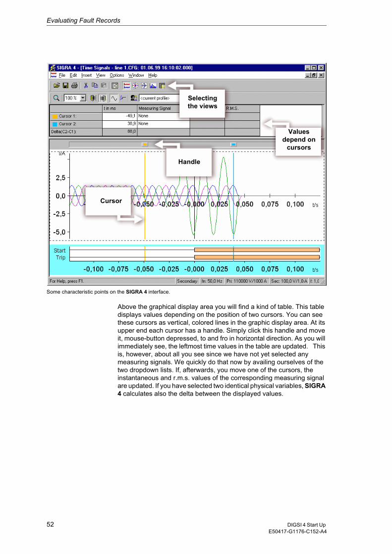
Evaluating Fault Records
Some characteristic points on the SIGRA 4 interface.
Above the graphical display area you will find a kind of table. This table displays values depending on the position of two cursors. You can see these cursors as vertical, colored lines in the graphic display area. At its upper end each cursor has a handle. Simply click this handle and move it, mouse-button depressed, to and fro in horizontal direction. As you will immediately see, the leftmost time values in the table are updated. This is, however, about all you see since we have not yet selected any measuring signals. We quickly do that now by availing ourselves of the two dropdown lists. If, afterwards, you move one of the cursors, the instantaneous and r.m.s. values of the corresponding measuring signal are updated. If you have selected two identical physical variables, SIGRA 4 calculates also the delta between the displayed values.
Valuesdepend on
cursors
Handle
Selecting the views
Cursor
52 DIGSI 4 Start Up E50417-G1176-C152-A4
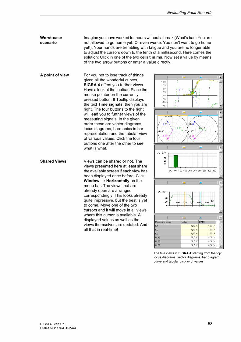
Evaluating Fault Records
top: m,
Worst-case scenario
Imagine you have worked for hours without a break (What's bad: You are not allowed to go home yet. Or even worse: You don't want to go home yet!). Your hands are trembling with fatigue and you are no longer able to adjust the cursors down to the tenth of a millisecond. Here comes the solution: Click in one of the two cells t in ms. Now set a value by means of the two arrow buttons or enter a value directly.
A point of view For you not to lose track of things given all the wonderful curves, SIGRA 4 offers you further views. Have a look at the toolbar. Place the mouse pointer on the currently pressed button. If Tooltip displays the text Time signals, then you are right. The four buttons to the right will lead you to further views of the measuring signals. In the given order these are vector diagrams, locus diagrams, harmonics in bar representation and the tabular view of various values. Click the four buttons one after the other to see what is what.
Shared Views Views can be shared or not. The views presented here at least share the available screen if each view has been displayed once before. Click Window ��Horizontally on the menu bar. The views that are already open are arranged correspondingly. This looks already quite impressive, but the best is yet to come. Move one of the two cursors and it will move in all views where this cursor is available. All displayed values as well as the views themselves are updated. And all that in real-time!
The five views in SIGRA 4 starting from the locus diagrams, vector diagrams, bar diagracurve and tabular display of values.
53DIGSI 4 Start UpE50417-G1176-C152-A4

Evaluating Fault Records
More for your money
Being a professional evaluation program, SIGRA 4 has a lot more to offer. To show you some of it, maximize the view of the time signals. At present SIGRA 4 shows the instantaneous and the r.m.s. value in the table above the graphic.To increase the informational content, right-click in the blank, white area to the right of the column r.m.s. value. From the context menu select View properties. Applying this command opens the dialog box with the same name. The tab Table columns contains two list boxes. The left list shows the names of the columns or values currently not displayed. The right list, however, states the names of the columns or values already displayed. To show new columns, select the corresponding name in the left list and click the arrow button pointing to the right list. Proceed similarly to hide columns. Use the buttons Up and Down to move a selected name in the right list in the corresponding direction. Thus you change the order in which the columns are displayed.»Once all changes made, click OK.«
Adaptable In the graphical display area you can see a number of curves and bars representing analog or binary measuring signals. The number of diagrams is set by default and contains an appropriate combination of signals. It is of course not ideal and can be adapted to your needs in any way you like. What options do you have for this? Well, you can add or remove measuring signals in an individual diagram. But you can also delete entire diagrams or complement them. We will perform the last mentioned action first.
Use the right mouse button to select the diagram above which you want to insert the new diagram. Select New from the context menu. An empty diagram is inserted. Double-click the diagram to open the dialog box Diagram properties. The box Name shows you the title SIGRA 4 has given the new diagram. Since we will use this diagram for exercising purposes, rename it into exercise diagram. Select the checkbox Name, to have the diagram name displayed.
Matrix II Right-click in the new diagram. Select the command Assign signals from the context menu. What you see now should seem familiar to you. As was done for allocating information items, we also use a matrix for assigning signals. The available diagrams are arranged horizontally. They are assigned to the corresponding diagram type. In vertical direction, the available signals are listed. They are comprised in different groups of signal types.
54 DIGSI 4 Start Up E50417-G1176-C152-A4
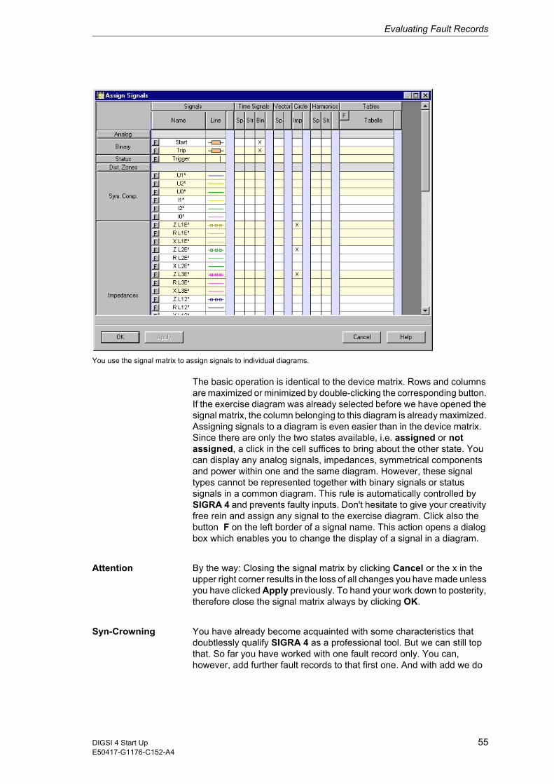
Evaluating Fault Records
You use the signal matrix to assign signals to individual diagrams.
The basic operation is identical to the device matrix. Rows and columns are maximized or minimized by double-clicking the corresponding button. If the exercise diagram was already selected before we have opened the signal matrix, the column belonging to this diagram is already maximized. Assigning signals to a diagram is even easier than in the device matrix. Since there are only the two states available, i.e. assigned or not assigned, a click in the cell suffices to bring about the other state. You can display any analog signals, impedances, symmetrical components and power within one and the same diagram. However, these signal types cannot be represented together with binary signals or status signals in a common diagram. This rule is automatically controlled by SIGRA 4 and prevents faulty inputs. Don't hesitate to give your creativity free rein and assign any signal to the exercise diagram. Click also the button F on the left border of a signal name. This action opens a dialog box which enables you to change the display of a signal in a diagram.
Attention By the way: Closing the signal matrix by clicking Cancel or the x in the upper right corner results in the loss of all changes you have made unless you have clicked Apply previously. To hand your work down to posterity, therefore close the signal matrix always by clicking OK.
Syn-Crowning You have already become acquainted with some characteristics that doubtlessly qualify SIGRA 4 as a professional tool. But we can still top that. So far you have worked with one fault record only. You can, however, add further fault records to that first one. And with add we do
55DIGSI 4 Start UpE50417-G1176-C152-A4
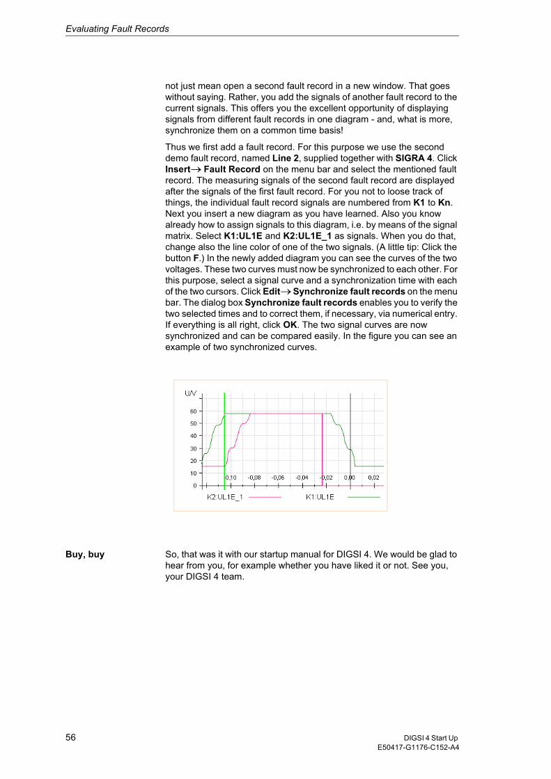
Evaluating Fault Records
not just mean open a second fault record in a new window. That goes without saying. Rather, you add the signals of another fault record to the current signals. This offers you the excellent opportunity of displaying signals from different fault records in one diagram - and, what is more, synchronize them on a common time basis!
Thus we first add a fault record. For this purpose we use the second demo fault record, named Line 2, supplied together with SIGRA 4. Click Insert��Fault Record on the menu bar and select the mentioned fault record. The measuring signals of the second fault record are displayed after the signals of the first fault record. For you not to loose track of things, the individual fault record signals are numbered from K1 to Kn. Next you insert a new diagram as you have learned. Also you know already how to assign signals to this diagram, i.e. by means of the signal matrix. Select K1:UL1E and K2:UL1E_1 as signals. When you do that, change also the line color of one of the two signals. (A little tip: Click the button F.) In the newly added diagram you can see the curves of the two voltages. These two curves must now be synchronized to each other. For this purpose, select a signal curve and a synchronization time with each of the two cursors. Click Edit��Synchronize fault records on the menu bar. The dialog box Synchronize fault records enables you to verify the two selected times and to correct them, if necessary, via numerical entry. If everything is all right, click OK. The two signal curves are now synchronized and can be compared easily. In the figure you can see an example of two synchronized curves.
Buy, buy So, that was it with our startup manual for DIGSI 4. We would be glad to hear from you, for example whether you have liked it or not. See you, your DIGSI 4 team.
56 DIGSI 4 Start Up E50417-G1176-C152-A4
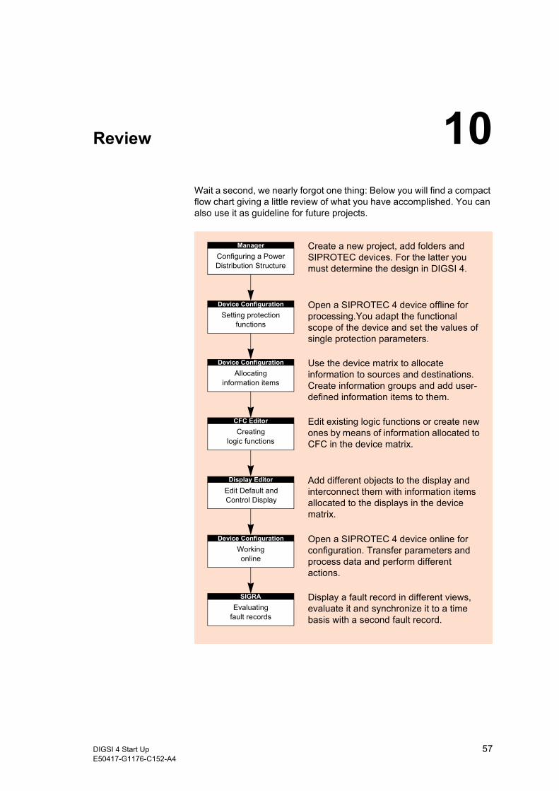
Review 10Wait a second, we nearly forgot one thing: Below you will find a compact flow chart giving a little review of what you have accomplished. You can also use it as guideline for future projects.
ManagerConfiguring a Power Distribution Structure
Create a new project, add folders and SIPROTEC devices. For the latter you must determine the design in DIGSI 4.
Device ConfigurationSetting protection
functions
Open a SIPROTEC 4 device offline for processing.You adapt the functional scope of the device and set the values of single protection parameters.
Device ConfigurationAllocating
information items
Use the device matrix to allocate information to sources and destinations. Create information groups and add user-defined information items to them.
CFC EditorCreating
logic functions
Edit existing logic functions or create new ones by means of information allocated to CFC in the device matrix.
Display EditorEdit Default and Control Display
Add different objects to the display and interconnect them with information items allocated to the displays in the device matrix.
Device ConfigurationWorkingonline
Open a SIPROTEC 4 device online for configuration. Transfer parameters and process data and perform different actions.
SIGRAEvaluating
fault records
Display a fault record in different views, evaluate it and synchronize it to a time basis with a second fault record.
57DIGSI 4 Start UpE50417-G1176-C152-A4

Review
58 DIGSI 4 Start Up E50417-G1176-C152-A4