

Digsi Manual XML a2 En
72
Edition: 23.04.08 E50417-F1176-C404-A2 DIGSI 4 DIGSI is talking XML Manual Table of contents What Awaits You 1 Little XML Science 2 Exporting and Importing with DIGSI 4 3 The DIGSI XML Code under the Microscope 4 Targeted Editing of Data 5 Safety Concept for the XML Import 6 Excel as Data Source 7 Exchanging Data with Applications from the Power Distribution Area 8 What Else You Should Know 9
-
Upload
alexander-guzman -
Category
Documents
-
view
158 -
download
5
Transcript of Digsi Manual XML a2 En

Edition: 23.04.08
E50417-F1176-C404-A2
DIGSI 4
DIGSI is talking XML
Manual
Table of contents
What Awaits You 1Little XML Science 2Exporting and Importing with DIGSI 4 3The DIGSI XML Code under the Microscope 4Targeted Editing of Data 5Safety Concept for the XML Import 6Excel as Data Source 7Exchanging Data with Applications from the Power Distribution Area 8What Else You Should Know 9

Information for Your Safety
This manual does not represent a complete listing of all the safety measures required to operate the equipment (module, device) since specific operating conditions may make fur-ther measures necessary. However, it contains information which you have to observe in order to ensure your personal safety and in order to avoid property damage. The informa-tion is highlighted by a warning triangle and, depending on the degree of danger, is shown as follows:
Warning
indicates that death, severe personal injury or substantial property damage can result if proper precautions are not taken.
Caution
indicates that minor personal injury or property damage can result if proper precautions are not taken.
Qualified personnel
Commissioning and operation of equipment (module, device) described in this manual may only be carried out by qualified personnel. Qualified personnel in the sense of the safety instructions in this manual are persons who are entitled to commission, enable, earth and identify devices, systems and circuits in accordance with the standards of safety technol-ogy.
Use as prescribed
The equipment (device, module) may only be used for the applications described in the catalogue and the technical specifications and only in combination with third party equipment recommended or approved by Siemens.
The successful and safe operation of this device is dependent on proper handling, storage, installation, operation, and maintenance.
Hazardous voltages are present in parts of this electrical equipment during operation. Severe personal injury or property damage can result if the device is not handled properly
• The device is to be earthed to the protective-earth terminal before any other connections are made.
• Hazardous voltages can arise in all the circuit parts connected to the power supply.
• Hazardous voltages can be present in the equipment even after the power supply voltage has been removed, i.e. capacitors can still be charged.
• Equipment with current transformer circuits may not be operated openly.
The limits specified in this manual or in the operating instructions respectively may not be exceeded. This point must also observed during testing and commissioning.
Siemens Aktiengesellschaft Buch-Nr. E50417-F1176-C404-A2
Disclaimer of LiabilityWe have checked the text of this manual for conformity with the hardware and software described. However, since deviations cannot be ruled out entirely, we do not accept liability for complete conformity or for any errors or omissions. The information in this manual is checked periodically, and necessary corrections will be included in future editions. We appreciate any suggestions for improvement.
We reserve the right to make technical improvements.Document version 1.01.00
CopyrightCopyright © Siemens AG 2008 All Rights ReservedThe reproduction, transmission or use of this document or its contents is not permitted without express written authority. Offenders will be liable for damages. All rights, including rights created by patent grant or registration of a utility model or design, are reserved.Registered TrademarksSIMATIC®, SIMATIC NET®, SIPROTEC® , DIGSI®, SICAM® and SINAUT® are registered trademarks of SIEMENS AG. Any other names used in this manual could be trademarks whose use by third persons for their respective purposes may violate proprietary rights.

Table of contents
1 What Awaits You . . . . . . . . . . . . . . . . . . . . . . . . . . . . . . . . . . . . . . . . . . . . . . . . . . . 5
2 Little XML Science . . . . . . . . . . . . . . . . . . . . . . . . . . . . . . . . . . . . . . . . . . . . . . . . . . 9
3 Exporting and Importing with DIGSI 4 . . . . . . . . . . . . . . . . . . . . . . . . . . . . . . . . . . 11
A Comparison of the Various Formats . . . . . . . . . . . . . . . . . . . . . . . . . . . . . . . . . . . 11
Exporting Device Data in XML. . . . . . . . . . . . . . . . . . . . . . . . . . . . . . . . . . . . . . . . . . 14
Importing Device Data in XML. . . . . . . . . . . . . . . . . . . . . . . . . . . . . . . . . . . . . . . . . . 15
4 The DIGSI XML Code under the Microscope . . . . . . . . . . . . . . . . . . . . . . . . . . . . 17
Opening the XML Code in the Editor. . . . . . . . . . . . . . . . . . . . . . . . . . . . . . . . . . . . . 17
Direct Assignment between Code and DIGSI 4 . . . . . . . . . . . . . . . . . . . . . . . . . . . . 19
Basic Structure of DIGSI XML . . . . . . . . . . . . . . . . . . . . . . . . . . . . . . . . . . . . . . . . . . 22
5 Targeted Editing of Data . . . . . . . . . . . . . . . . . . . . . . . . . . . . . . . . . . . . . . . . . . . . . 27
Reducing the Code . . . . . . . . . . . . . . . . . . . . . . . . . . . . . . . . . . . . . . . . . . . . . . . . . . 27
Changing Individual Parameter Values . . . . . . . . . . . . . . . . . . . . . . . . . . . . . . . . . . . 28
Importing an XML Segment. . . . . . . . . . . . . . . . . . . . . . . . . . . . . . . . . . . . . . . . . . . . 30
Copying Complete Function Settings . . . . . . . . . . . . . . . . . . . . . . . . . . . . . . . . . . . . 31
Changing Routings and Properties of Existing Information . . . . . . . . . . . . . . . . . . . . 33
Generating and Deleting User-defined Information and Groups . . . . . . . . . . . . . . . . 34
3DIGSI 4 - DIGSI is talking XMLE50417-F1176-C404-A2
6 Safety Concept for the XML Import . . . . . . . . . . . . . . . . . . . . . . . . . . . . . . . . . . . . 37
Device Validation . . . . . . . . . . . . . . . . . . . . . . . . . . . . . . . . . . . . . . . . . . . . . . . . . . . . 37
Syntax Check. . . . . . . . . . . . . . . . . . . . . . . . . . . . . . . . . . . . . . . . . . . . . . . . . . . . . . . 39
Plausibility Control . . . . . . . . . . . . . . . . . . . . . . . . . . . . . . . . . . . . . . . . . . . . . . . . . . . 41
7 Excel as Data Source . . . . . . . . . . . . . . . . . . . . . . . . . . . . . . . . . . . . . . . . . . . . . . . 43
Installing the Add-In . . . . . . . . . . . . . . . . . . . . . . . . . . . . . . . . . . . . . . . . . . . . . . . . . . 44
Creating and Editing a New Setting Sheet . . . . . . . . . . . . . . . . . . . . . . . . . . . . . . . . 46
Copying Parameters . . . . . . . . . . . . . . . . . . . . . . . . . . . . . . . . . . . . . . . . . . . . . . . . . 48
Exporting the Setting Data in XML Code and Importing It in DIGSI . . . . . . . . . . . . . 51
Preparing an Existing Setting Sheet for the XML Export . . . . . . . . . . . . . . . . . . . . . . 53
Special Case: Adopting Settings from Analog Siemens Protective Gear . . . . . . . . . 54
8 Exchanging Data with Applications from the Power Distribution Area . . . . . . . 57
Line Calculation . . . . . . . . . . . . . . . . . . . . . . . . . . . . . . . . . . . . . . . . . . . . . . . . . . . . . 57
Protection Test. . . . . . . . . . . . . . . . . . . . . . . . . . . . . . . . . . . . . . . . . . . . . . . . . . . . . . 58
Line and Protective Data Management . . . . . . . . . . . . . . . . . . . . . . . . . . . . . . . . . . . 58
9 What Else You Should Know . . . . . . . . . . . . . . . . . . . . . . . . . . . . . . . . . . . . . . . . . 59
4 DIGSI 4 - DIGSI is talking XML E50417-F1176-C404-A2

What Awaits You 1A hearty welcome and a good Tag. Tag? Yes, you read correctly. Of course, we also wish you a good day, but Tags, more exactly XML Tags, will accompany us through this entire book. And, if in the end, we should have convinced you that DIGSI XML makes your life easier, then they may even accompany you through your entire life. But in order to get there we have to start small, as usual, with an overview of that which awaits you.
XML is XXL With the import and export interface based on XML (extensible markup language) new, cost-saving opportunities open up for you with DIGSI as of Version 4.8: via the import interface, you can read data into DIGSI 4 from other applications and in this manner parameterize devices from outside. Vice versa, you transfer the setting data into other applications in order to further process them there. With the XML interface you open up a multitude of new applications. And you use the potential of familiar applications much better since you can now integrate them optimally in your workflow. You could also put it this way: With DIGSI XML your benefits are XXL:
• reduced error frequency,
• complete security,
• marginal learning time,
• increased productivity
• and practically no costs!
Ambitious The data output of most other setting programs is limited to simple ASCII text or in some cases uses the CSV database format. Siemens, on the other hand, has pursued the strategy right from the beginning of offering a universal, platform-independent and future-oriented format for DIGSI 4 that is based on the standardized descriptive language XML.
In DIGSI XML, standard-conform XML tags are offered that on the one hand reflect the structure of the parameter set and on the other the meaning of the parameters. Only what is visible in the DIGSI 4 user interface or is found in the appendix of any device manual goes into the XML file. Thus, the DIGSI XML format has decisive benefits from your viewpoint: It is easy to read and to understand, is structured with only a few levels and you can learn it quickly.
5DIGSI 4 - DIGSI is talking XMLE50417-F1176-C404-A2
What Awaits You
Chapters of their own
If you already have some knowledge of XML it definitely means that you are a bit ahead of the others. But this knowledge isn’t absolutely necessary in order to understand DIGSI XML. In Chapter 2 Little XML Science, we will provide you with a basis, in the form of several basic terms, that is more than sufficient to understand and be able to apply DIGSI XML.
We will get right down to the business of our actual topic in Chapter 3 Exporting and Importing with DIGSI 4. There we will use the opportunity to give you an overview of all possible DIGSI 4 import and export formats. Then, we will describe the procedures for exporting and importing data in XML.
In Chapter 4 The DIGSI XML Code under the Microscope, we will unpack our microscopic tools and perform an autopsy of the structure and contents of a DIGSI XML file. It will be a completely bloodless procedure since we don’t have to do any cutting: the code is open to all right from the beginning.
The knowledge that we’ve gathered by then will be used in Chapter 5 Targeted Editing of Data for the practical application. After studying these pages you will be able - just like the great cooking masters, to get more flavor through reduction. Clearly put: We will show you how you can shrink the code in the best case to only a few lines.
The parameter set is sacred, that much is clear. Chapter 6 Safety Concept for the XML Import therefore shows you to what lengths DIGSI 4 goes so that nothing goes wrong when importing XML data.
Many users manage setting data with the help of Microsoft’s Excel and often use its capabilities to calculate values with all sorts of formulas. Reason enough for Siemens to develop one macro and one add-in that organize the data exchange between Excel and DIGSI 4 considerably more effectively. Everything you need to know on this, you’ll find in Chapter 7 Excel as Data Source.
One topic that is of great importance for many is surely the exchanging of data with other applications that are at home in the power distribution area. Programs for line calculation or protection testing are examples of this. Nevertheless, we will only go into it very briefly in this manual. The reason being that you don’t need any special knowledge for this as far as DIGSI 4 is concerned. You export the data in XML or XRIO and you’re already at your goal. In Chapter 8 Exchanging Data with Applications from the Power Distribution Area you’ll only find a short fundamental overview.
Our What Else You Should Know - chapter with the Number 9 once again forms the conclusion of the book. There you will find a tabular overview of information numbers this time. What this is all about, you’ll find out in one of the next chapters.
6 DIGSI 4 - DIGSI is talking XMLE50417-F1176-C404-A2

What Awaits You
Call me If you have additional questions on this topic, our Hotline would be more than happy to help you:
Tel.: 01 80 - 5 24 70 00Fax: 01 80 - 5 24 24 71e-mail: [email protected]
Training You can obtain the individual course offerings from our Training Center. There, Siemens offers you extensive courses on working with DIGSI 4.
Siemens AGPower Transmission and DistributionEnergy AutomationHumboldtstr. 5990459 NurembergTel.: +49 9 11/4 33-70 05Fax: +49 9 11/4 33-79 29Internet www.siemens.com/power-academy-td
Beyond the horizon there´s more
If you’re interesting in more information, here are two order numbers on the topic of DIGSI 4 and SIPROTEC.
• DIGSI 4 Start Up manual C50417-G1176-C152-A4
• SIPROTEC 4 Tutorial DVD E50001-U310-D21-X-7100
And now, have fun!
7DIGSI 4 - DIGSI is talking XMLE50417-F1176-C404-A2

Little XML Science 2Based on William Tunnicliffe’s concept of Generic Coding, the separation of contents and form, you can no longer do without XML today. It stretches through practically all areas of the software world and enables connections that were not thought to be possible previously or at least could only be implemented with a great deal of effort.
Simple, not trivial
Even if the basic idea of XML is the simplification of handling, it doesn’t mean that an XML document must therefore be necessarily trivial. To be sure, there are XML characteristics that can be called sophisticated. Luckily, our developers have managed to depict the data from a SIPROTEC 4 device in an easy to understand XML structure. You will become familiar with the special structure in Chapter 4. Here and now we will inform you of the basic terms and the best way to do that is with an example:
A code says more than a thousand words: Insights into XML and the life of the author.
Elementary parts An XML code consists of elements. Author and Characteristics are such elements, but also Performance, Wages and Charity Account. Each element can have attributes and contents - but it doesn’t have to. The element Author, for example, has the two attributes Name and Job. Each attribute has its value that is attached to the attribute name in the form of ="Value".
The content of an element can be a further element, such as is the case for Author and Characteristics. The elements Performance and Wages, on the other hand, simply have text as the content, namely maximum and minimum.
You can choose almost anything as the element names. You must, however, avoid some special characters.
<Author Name="Gerald Gutwin" Job="Heavy laborer">
<Characteristics>
<Performance>maximum</Performance>
<Wages>minimum</Wages>
</Characteristics>
<Charity Account="02 346 829" BLZ="01010101" />
</Author>
9DIGSI 4 - DIGSI is talking XMLE50417-F1176-C404-A2
Little XML Science
Tic Tag Toe Elements, either with or without attributes, are always enclosed in two V-shaped brackets. Constructions such as <Characteristics> are called Tags. In this case, it is an opening Tag, in other words, the beginning of the following content. The end of this content must also be marked. For this, a slash is added and there you have a closing Tag: </Characteristics>. The name of the element, in this case Characteristics, can also be called Tag Name. By the way, only the element in an opening Tag can have attributes.
If an element only has attributes but no content, you may deviate from the described structure and get by with only one single Tag: <Charity Account="02 346 829" BLZ="01010101" />.
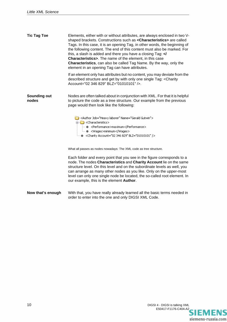
Sounding out nodes
Nodes are often talked about in conjunction with XML. For that it is helpful to picture the code as a tree structure. Our example from the previous page would then look like the following:
What all passes as nodes nowadays: The XML code as tree structure.
Each folder and every point that you see in the figure corresponds to a node. The nodes Characteristics and Charity Account lie on the same structure level. On this level and on the subordinate levels as well, you can arrange as many other nodes as you like. Only on the upper-most level can only one single node be located, the so-called root element. In our example, this is the element Author.
Now that’s enough With that, you have really already learned all the basic terms needed in order to enter into the one and only DIGSI XML Code.
10 DIGSI 4 - DIGSI is talking XMLE50417-F1176-C404-A2
Exporting and Importing with DIGSI 4 3You could already export and import data with DIGSI 4 right from the beginning. In the course of the various versions, formats were always added so as to fulfill the ever-changing requirements of the user. That is why we want to use this chapter, among other things, to explain all the possible import and export formats of DIGSI 4 in a brief overview. After that, we will show you how easy it is to export data into the XML format and then reimport it into DIGSI 4.
A Comparison of the Various Formats
The exporting and importing of data in the different formats is always connected to the current work situation. That is why you can trigger appropriate actions in the DIGSI Manager (export and import) as well as in the DIGSI Device Editor (only export). On the next pages we have summarized which formats are possible from where, whether it only functions in one or in both directions and which menu commands you need for it.
• DEXDirection: Export/ImportContents: All device dataProgram level: DIGSI Manager Commands: Edit → Export device, Edit → Import device
DEX is the format that you choose to get a complete data image of a device in one single file. You use this bidirectional format to archive device data completely or even to exchange it between different projects. You can only use the DEX format within DIGSI 4 and you cannot edit it.
• XML (for protective data)Direction: Export/ImportContents: Protective dataProgram level: DIGSI Manager Commands: Edit → Export device, Edit → Import device
XML for protective data or simply DIGSI XML is the format that it’s all about on these roughly 60 pages.
The DIGSI XML format has the decided advantage that, on the one hand, it enables data exchange with other applications and on the other that it also permits the targeted changing of individual parameter values. This
11DIGSI 4 - DIGSI is talking XMLE50417-F1176-C404-A2
Exporting and Importing with DIGSI 4
becomes possible through its readable and manually editable format. However, only protective parameter settings and routings can be exported, edited and reimported.
Settings for CFC and the device display have to stay on the outside. Also process data such as indications and measured values (with the exception of extended measured values) don´t flow into the XML file.
• XRIODirection: ExportContents: Protective dataProgram levels: DIGSI Manager, DIGSI Device EditorCommands: Edit → Export device (DIGSI Manager), File → Export → Configuration & Protection parameters (DIGSI Device Editor)
The XRIO format was developed by the OMICRON Company based on the RIO format in order to be able to pass data from a protective configuration system, in our case DIGSI 4, to their test systems. You can open files in the XRIO format without further ado using an XML editor; after all, it is also a matter of XML code. However, identifiers, contents and structure differ clearly from the DIGSI XML code.
• XML (for system interface)Direction: ExportContents: System interface dataProgram level: DIGSI Device Editor Command: File → Export → System interface (XML)
With the help of this export format, a station control system can read in all information that is routed in DIGSI 4 on an IEC 60870-5-103 system interface. But watch out: This XML export has nothing to do with what we are dealing with extensively in this book. Of course, the structure of the exported code conforms in principle to the XML conventions. But the contents of the export file is limited exclusively to the mentioned interface data.
• DBFDirection: ExportContents: System interface dataProgram level: DIGSI Device EditorCommand: File → Export → System interface (dBase)
The dBase format DBF was developed at the beginning of the 1990s and is still a commonly used alternative to XML for connecting to instrumentation and control systems. Here, as well, DIGSI 4 exports exclusively data of the IEC 60870-103 system interface.
12 DIGSI 4 - DIGSI is talking XMLE50417-F1176-C404-A2

Exporting and Importing with DIGSI 4
• ELC (ASCII for ELCAD)Direction: ExportContents: Protective dataProgram level: DIGSI Device EditorCommand: File → Export → Configuration & Protection parameters
In the ELCAD format, the parameter values and routings are stored in a file distributed on individual pages. This file can only be opened by current ELCAD program versions. Older program versions are not capable of importing several pages from one file.
• CSVDirection: ExportContents: Protective dataProgram level: DIGSI Device Editor File → Export → Configuration & Protection parameters
In the CSV format (Comma Separated Values), the data is stored in a file line-by-line and separated by semicolons. Such files can be opened by many spread-sheet programs, even Excel. Disadvantages vis-a-vis DIGSI-XML: After importing in Excel, the data is presented in a rather uninviting layout. There is also no way back to DIGSI 4.
• PDFDirection: ExportContents: System interface dataProgram level: DIGSI Device Editor Command: File → Export → IEC 61850 system interface for documentation (PDF)
The data of an IEC 61850-system interface can be exported in the PDF format for purely documentation purposes. The IEC 61850 Standard refers to this type of export as MICS (Model Implementation Conformance Statement). It is the readable form of the data contained in the device description file (ICD).
Conclusion XML is THE format if you require a flexible and easy parameterization of protective settings, that also enables you to further use data already existing in Excel without having to type it all again. Whoever has to archive all device data, though, for example also settings for CFC and the device display continues to use the DEX format.
13DIGSI 4 - DIGSI is talking XMLE50417-F1176-C404-A2

Exporting and Importing with DIGSI 4
Exporting Device Data in XML
In order to get DIGSI 4 to export the data of a device into XML, you proceed in principle just as you always have when you exported it in the DEX format. Clearly put: You right-click on the symbol of the device concerned and select the command Export device from the pop-up menu.
Business as usual: The command for exporting is the same as for exporting in the DEX format.
But wait! One prerequisite must be fulfilled so that DIGSI 4 starts with the data export. The device, whose data is to be converted into the XML format, must have been opened at least once with the DIGSI Device Editor. Should you have forgotten that, nothing earthshattering will happen. DIGSI 4 will simply make you aware of it and you can quickly correct it. Now let’s continue!
Accept suggestion or improve on it: Select Name and Directory
14 DIGSI 4 - DIGSI is talking XMLE50417-F1176-C404-A2

Exporting and Importing with DIGSI 4
DIGSI 4 opens the Export dialog and you choose XML as the export format. If you don’t like the file name suggested by DIGSI 4, you can, of course, change it and then you can also define a destination directory. One click on OK starts the export, the progress and result of which you can follow in the Report window. It should look something like the following picture.
Everything looks good: The Report shows only positive messages.
Log book The Report window shows you warnings and success messages and with that a compressed overview. You get all the details by looking into the Log files that DIGSI 4 writes during the export (and also import). To find the path to these files, open the Object Properties dialog of the device concerned and click on the DIGSI Manager tab. The dialog then shows you a path that you follow up in the Explorer. When you get to the specified destination directory you then switch to the subdirectory Para and there you will find the two files XmlExport.log and XmlImport.log, both of which are very normal text files. By the way: With each import or export, the content of the respective file is overwritten.
Importing Device Data in XML
To import the device data in the XML format into a device, right-click on it in the DIGSI Manager. From the pop-up menu, select Import device and that way open the Import dialog (see next page).
By comparison In the lower half it shows you several characteristic data of the chosen device. This serves as orientation help in the selection of data to be imported. As soon as you have marked the name of the import file in the selection field, DIGSI 4 also shows some key data on the device that is hidden behind this XML code. Possibly at least. Since you could be dealing with a greatly reduced XML file, that doesn’t necessarily have to contain any information on a particular device, the information displayed could be quite skimpy.
15DIGSI 4 - DIGSI is talking XMLE50417-F1176-C404-A2
Exporting and Importing with DIGSI 4
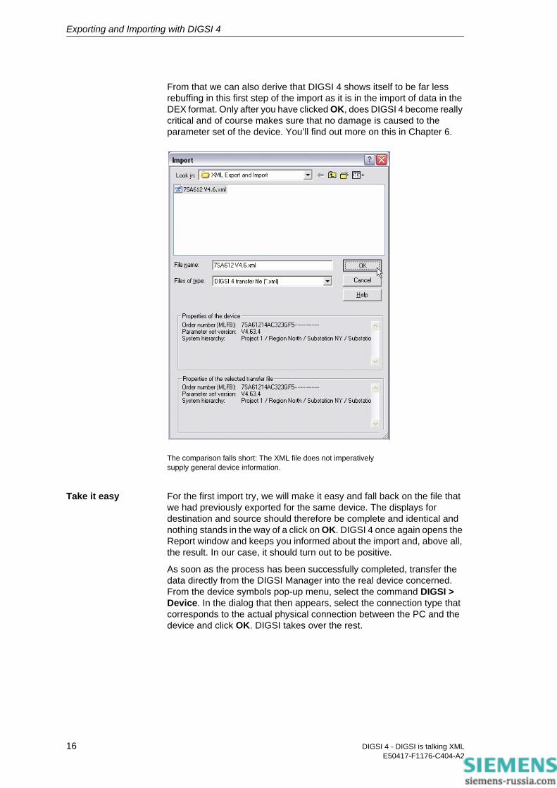
From that we can also derive that DIGSI 4 shows itself to be far less rebuffing in this first step of the import as it is in the import of data in the DEX format. Only after you have clicked OK, does DIGSI 4 become really critical and of course makes sure that no damage is caused to the parameter set of the device. You’ll find out more on this in Chapter 6.
The comparison falls short: The XML file does not imperatively supply general device information.
Take it easy For the first import try, we will make it easy and fall back on the file that we had previously exported for the same device. The displays for destination and source should therefore be complete and identical and nothing stands in the way of a click on OK. DIGSI 4 once again opens the Report window and keeps you informed about the import and, above all, the result. In our case, it should turn out to be positive.
As soon as the process has been successfully completed, transfer the data directly from the DIGSI Manager into the real device concerned. From the device symbols pop-up menu, select the command DIGSI > Device. In the dialog that then appears, select the connection type that corresponds to the actual physical connection between the PC and the device and click OK. DIGSI takes over the rest.
16 DIGSI 4 - DIGSI is talking XMLE50417-F1176-C404-A2
The DIGSI XML Code under the Microscope 4In this chapter, we would like to take a closer look at the XML code exported by DIGSI 4. You will see that it is neither a question of witchcraft nor complex information that is only accessible to a few experts. On the contrary, you will quickly arrive at the conclusion that DIGSI 4 structures the required information for you well and presents it to you in appetizing morsels. And, with only a little exercise, you will quickly advance to professional and doing the applications presented in the next chapters will be a piece of cake for you.
Opening the XML Code in the Editor
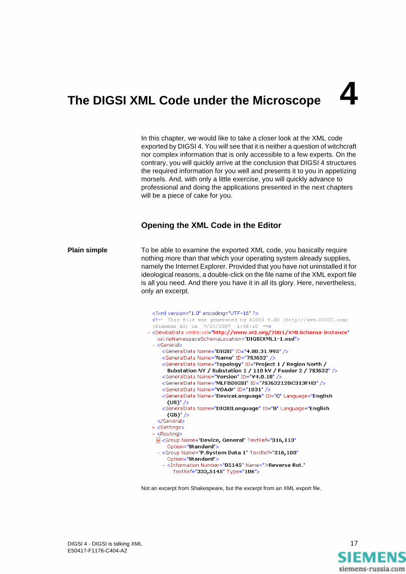
Plain simple To be able to examine the exported XML code, you basically require nothing more than that which your operating system already supplies, namely the Internet Explorer. Provided that you have not uninstalled it for ideological reasons, a double-click on the file name of the XML export file is all you need. And there you have it in all its glory. Here, nevertheless, only an excerpt.
Not an excerpt from Shakespeare, but the excerpt from an XML export file.
17DIGSI 4 - DIGSI is talking XMLE50417-F1176-C404-A2
The DIGSI XML Code under the Microscope
The code is structured in different levels that are differently indented and thus can easily be distinguished from one another. Little minus and plus signs allow you to hide or once again display the contents of individual levels and nodes using a mouse-click. You lose this comfort feature, however, as soon as you wish to edit the code using standard tools. Because, after choosing View → Source text, Windows opens the code in Notepad and this doesn’t allow you to even indent individual lines with the tabulator key.
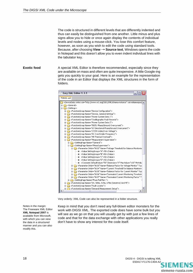
Exotic food A special XML Editor is therefore recommended, especially since they are available on mass and often are quite inexpensive. A little Google-ing gets you quickly to your goal. Here is an example for the representation of the code in an Editor that displays the XML structures in the form of folders.
Very orderly: XML Code can also be represented in a folder structure.
Notes in the margin:The Freeware XML Editor XML Notepad 2007 is available from Microsoft, with which you can view the data in a structured manner and you can also modify this.
Keep in mind that you don’t need any full-blown editor monsters for the work with DIGSI XML. The exported code does have some bulk but you will see as we go on that you will usually get by with just a few lines of code and that for the data exchange with other applications you really don’t have to show any interest for the code itself.
18 DIGSI 4 - DIGSI is talking XMLE50417-F1176-C404-A2

The DIGSI XML Code under the Microscope
Direct Assignment between Code and DIGSI 4
If the volume of the XML code exported by DIGSI 4 gives you a feeling of uneasiness at first glance, we can put your mind to rest: As far as the contents are concerned you basically don’t see anything new other than that which you otherwise also get to see within the framework of the DIGSI Device Editor. You only see the contents in another format.
Without any doubts To make sure that you don’t have any more doubts, we would like to bolster this statement by means of a small code excerpt, before we devote ourselves to the complete structure of the code. (The code excerpt in reality also contains the data on the rest of the three parameters of the dialog register; we have left them out of the figure to make it easier to understand.)
XML code and DIGSI 4: Always in dialog with one another.
<FunctionGroup Name="50/51 Phase/Ground Overcurrent">
<SettingPage Name="50">
<Parameter DAdr="1202" Name="50-2 Pickup" Type="Dec">
<Value>2.00</Value>
<Comment Dimension="A" MinValue="0.10" MaxValue="35.00"/>
<Comment AdditionalValidValues="oo" DefaultValue="2.00"/>
</Parameter>
</SettingPage>
</FunctionGroup>
1
2 43
5
12
34
5
19DIGSI 4 - DIGSI is talking XMLE50417-F1176-C404-A2

The DIGSI XML Code under the Microscope
Numbered The excerpt shows you parts of the function 50/51 Phase/Ground Overcurrent. Directly underneath, you can see the matching dialog from the DIGSI Device Editor. We have given each of the corresponding elements the same numbers.
The excerpt shows that the DIGSI XML code contains XML tags conforming to standard that, on the one hand, reproduce the structure of the parameter set and, on the other, the meaning of the parameter. We have even gone one step further in the conversion: only that which is visible in the DIGSI 4 user interface or, if necessary, is listed in the appendix of any device manual goes into the XML file. But let’s not beat about the bush.
XML Connections The previously shown excerpt from a DIGSI XML file begins with the tag <FunctionGroup Name="50/51 Phase/Ground Overcurrent“>. The element FunctionGroup leads us to the following DIGSI 4 dialog:
Group structure: All Function groups find themselves in this dialog again.
This dialog gives you in DIGSI 4 an overview of the configured functions and at the same time the opportunity to open these for editing. One of these functions is the Overcurrent time protection. In the tag shown, 50/51 Phase/Ground Overcurrent is the value of the attribute Name. In this way, the connection between the selection dialog and also the dialog for editing the function is established, for you will find 50/51 Phase/Ground Overcurrent in the title bar of this again.
The parameters for the overcurrent time protection are classified by topic into several dialog tabs to make them more transparent. These are also called Setting pages. The tag <SettingPage Name="50"> gives you information, by means of the attribute value, in which dialog register in DIGSI 4 you would find the parameters that follow in the code.
20 DIGSI 4 - DIGSI is talking XMLE50417-F1176-C404-A2
The DIGSI XML Code under the Microscope
In our case it is the tab 50. It contains four parameters and in the code, as well, you find the description of four parameters between the opening tag <SettingPage Name="50"> and the closing tag </SettingPage>.
Even if you can’t see it: the style of the representation is the same in all cases. The tag reveals through its name Parameter what it’s all about. The three attributes DAdr, Name and Type uniquely identify the parameter. DAdr stands for the Direct address, in the example 1202. The value of the attribute Name is nothing more than the identifier of the parameter, here 50-2 Pickup. And with the attribute Type you get the information of whether it is, as in this case, a Decimal parameter or a Text selection parameter.
Commentary of value
You will find the value of the parameter one level lower, framed by two tags, in the form <Value>2.00</Value>. On this level, the code more or less also presents comment tags. The quantity of these tags depends on the respective parameter for these tags contain parameter-specific information. For decimal parameters these are, for example, the physical unit or the validity range within which values are permitted. The counterpart to this comment line is a Tooltip in DIGSI 4 that appears as soon as you position the mouse pointer on the input field in the dialog. This tooltip then also shows you the permitted value limits.
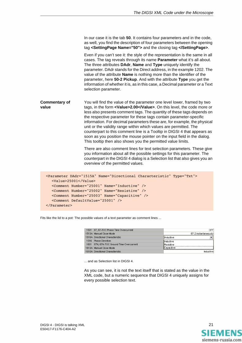
There are also comment lines for text selection parameters. These give you information about all the possible settings for this parameter. The counterpart in the DIGSI 4 dialog is a Selection list that also gives you an overview of the permitted values.
Fits like the lid to a pot: The possible values of a text parameter as comment lines ...
... and as Selection list in DIGSI 4.
As you can see, it is not the text itself that is stated as the value in the XML code, but a numeric sequence that DIGSI 4 uniquely assigns for every possible selection text.
<Parameter DAdr="1515A" Name="Directional Characteristic" Type="Txt">
<Value>25001</Value>
<Comment Number="25001" Name="Inductive" />
<Comment Number="25002" Name="Resistive" />
<Comment Number="25003" Name="Capacitive" />
<Comment DefaultValue="25001" />
</Parameter>
21DIGSI 4 - DIGSI is talking XMLE50417-F1176-C404-A2
The DIGSI XML Code under the Microscope
Speechless Just a few words on the linguistics within the code. The individual elements are always presented with English terms. Contents such as parameter identifiers and textual parameter values, on the other hand, are exported by DIGSI 4 in the respective national language preset in the parameter set. What appears as a supposed irregularity at first glance gives you the advantage that you can directly read the contents of the exported code. However, DIGSI 4 ignores these national language elements during import of parameter values. You can therefore also leave these out in this case and, as you will see, reduce the code, depending on the application, to a few lines that then no longer contains any national language elements.
Basic Structure of DIGSI XML
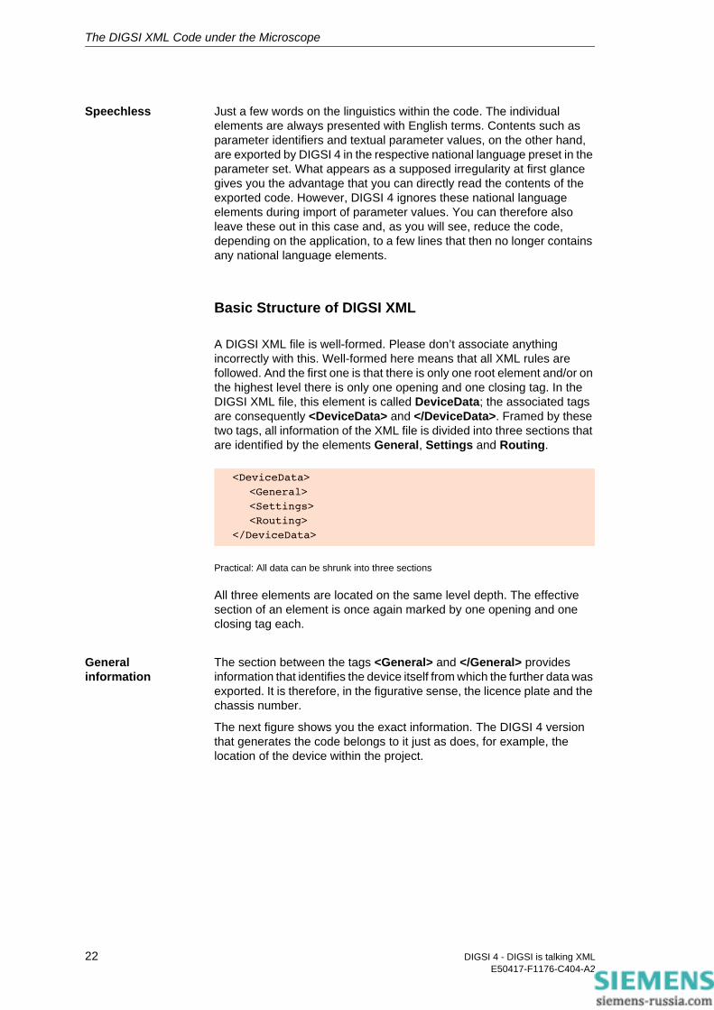
A DIGSI XML file is well-formed. Please don’t associate anything incorrectly with this. Well-formed here means that all XML rules are followed. And the first one is that there is only one root element and/or on the highest level there is only one opening and one closing tag. In the DIGSI XML file, this element is called DeviceData; the associated tags are consequently <DeviceData> and </DeviceData>. Framed by these two tags, all information of the XML file is divided into three sections that are identified by the elements General, Settings and Routing.
Practical: All data can be shrunk into three sections
All three elements are located on the same level depth. The effective section of an element is once again marked by one opening and one closing tag each.
General information
The section between the tags <General> and </General> provides information that identifies the device itself from which the further data was exported. It is therefore, in the figurative sense, the licence plate and the chassis number.
The next figure shows you the exact information. The DIGSI 4 version that generates the code belongs to it just as does, for example, the location of the device within the project.
<DeviceData>
<General>
<Settings>
<Routing>
</DeviceData>
22 DIGSI 4 - DIGSI is talking XMLE50417-F1176-C404-A2
The DIGSI XML Code under the Microscope
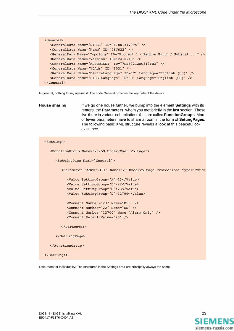
In general, nothing to say against it: The node General provides the key data of the device.
House sharing If we go one house further, we bump into the element Settings with its renters, the Parameters, whom you met briefly in the last section. These live there in various cohabitations that are called FunctionGroups. More or fewer parameters have to share a room in the form of SettingPages. The following basic XML structure reveals a look at this peaceful co-existence.
Little room for individuality: The structures in the Settings area are principally always the same.
<General>
<GeneralData Name="DIGSI" ID="4.80.31.995" />
<GeneralData Name="Name" ID="7SJ632" />
<GeneralData Name="Topology" ID="Project 1 / Region North / Substat ..." />
<GeneralData Name="Version" ID="V4.0.18" />
<GeneralData Name="MLFBDIGSI" ID="7SJ63212BC313FH3" />
<GeneralData Name="VDAdr" ID="1031" />
<GeneralData Name="DeviceLanguage" ID="C" Language="English (US)" />
<GeneralData Name="DIGSILanguage" ID="C" Language="English (US)" />
</General>
<Settings>
<FunctionGroup Name="27/59 Under/Over Voltage">
<SettingPage Name="General">
<Parameter DAdr="5101" Name="27 Undervoltage Protection" Type="Txt">
<Value SettingGroup="A">23</Value>
<Value SettingGroup="B">22</Value>
<Value SettingGroup="C">23</Value>
<Value SettingGroup="D">12700</Value>
<Comment Number="23" Name="OFF" />
<Comment Number="22" Name="ON" />
<Comment Number="12700" Name="Alarm Only" />
<Comment DefaultValue="23" />
</Parameter>
</SettingPage>
</FunctionGroup>
</Settings>
23DIGSI 4 - DIGSI is talking XMLE50417-F1176-C404-A2
The DIGSI XML Code under the Microscope
>
Notes in the margin:The size of the values divulges it immediately: DIGSI 4 always exports secondary values - and also expects such during import.
What we had still withheld in the preceding section, but you can now well recognize, is the influence of the setting group on the code. During export, DIGSI 4 supplements the element Value with the attribute SettingGroup that can have the values A, B, C or D. In that way differently set parameter values can also be brought into the setting groups in the XML code. By the way, DIGSI 4 always exports parameters that are part of a setting group in the manner shown, even if you have deactivated the setting group configuration and have never set different parameter values. In this case, one identical parameter value is displayed for all four setting groups.
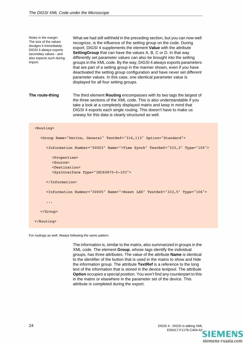
The route-thing The third element Routing encompasses with its two tags the largest of the three sections of the XML code. This is also understandable if you take a look at a completely displayed matrix and keep in mind that DIGSI 4 exports each single routing. This doesn’t have to make us uneasy for this data is clearly structured as well.
For routings as well: Always following the same pattern.
The information is, similar to the matrix, also summarized in groups in the XML code. The element Group, whose tags identify the individual groups, has three attributes. The value of the attribute Name is identical to the identifier of the button that is used in the matrix to show and hide the information group. The attribute TextRef is a reference to the long text of the information that is stored in the device textpool. The attribute Option occupies a special position. You won’t find any counterpart to this in the matrix or elsewhere in the parameter set of the device. This attribute is completed during the export.
<Routing>
<Group Name="Device, General" TextRef="316,113" Option="Standard">
<Information Number="00003" Name=">Time Synch" TextRef="333,3" Type="105"
<Properties>
<Source>
<Destination>
<SysInterface Type="IEC60870-5-103">
</Information>
<Information Number="00005" Name=">Reset LED" TextRef="333,5" Type="106">
...
</Group>
</Routing>
24 DIGSI 4 - DIGSI is talking XMLE50417-F1176-C404-A2
The DIGSI XML Code under the Microscope
Depending on the value set, it only unfolds its effect once it is reimported into the device. Put briefly, this attribute is important as soon as you want to manipulate individual groups and information. Since this is the topic of the next chapter, we ask for your patience.
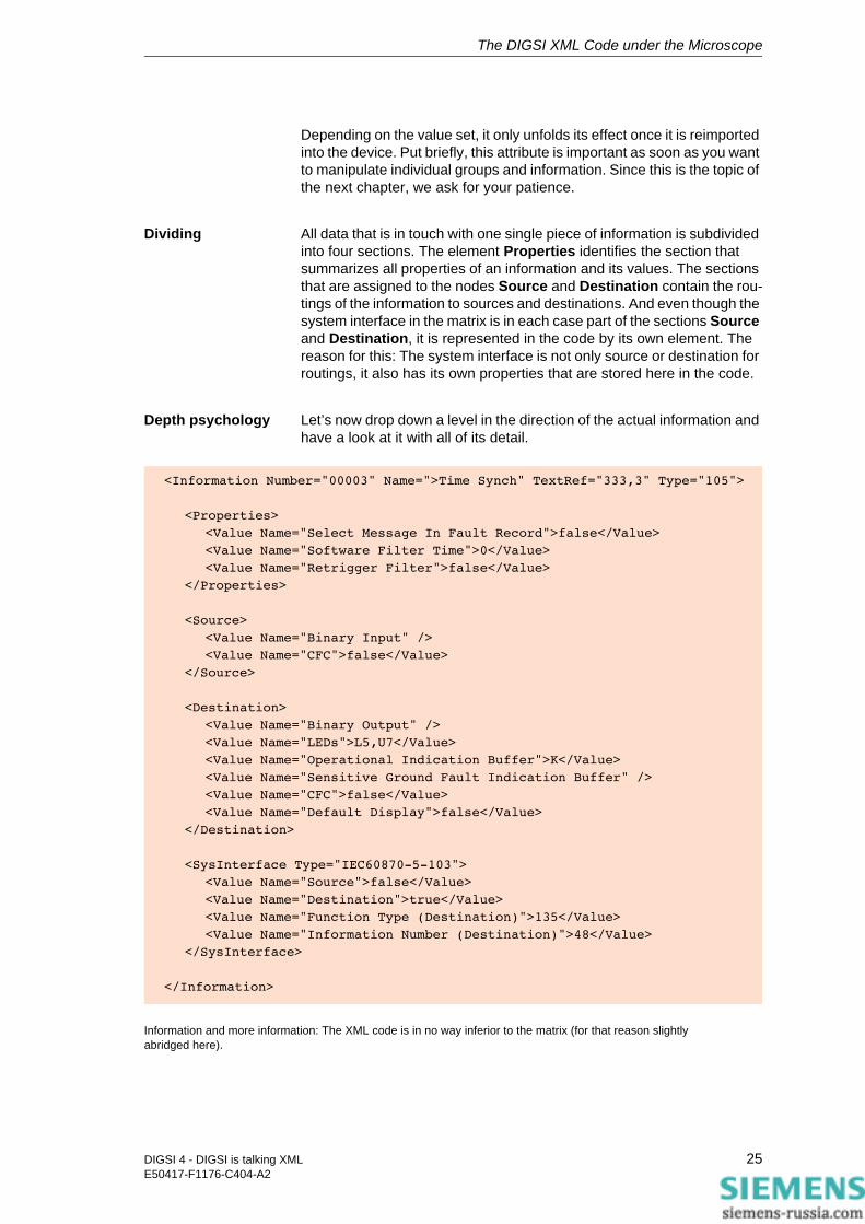
Dividing All data that is in touch with one single piece of information is subdivided into four sections. The element Properties identifies the section that summarizes all properties of an information and its values. The sections that are assigned to the nodes Source and Destination contain the rou-tings of the information to sources and destinations. And even though the system interface in the matrix is in each case part of the sections Source and Destination, it is represented in the code by its own element. The reason for this: The system interface is not only source or destination for routings, it also has its own properties that are stored here in the code.
Depth psychology Let’s now drop down a level in the direction of the actual information and have a look at it with all of its detail.
Information and more information: The XML code is in no way inferior to the matrix (for that reason slightly abridged here).
<Information Number="00003" Name=">Time Synch" TextRef="333,3" Type="105">
<Properties>
<Value Name="Select Message In Fault Record">false</Value>
<Value Name="Software Filter Time">0</Value>
<Value Name="Retrigger Filter">false</Value>
</Properties>
<Source>
<Value Name="Binary Input" />
<Value Name="CFC">false</Value>
</Source>
<Destination>
<Value Name="Binary Output" />
<Value Name="LEDs">L5,U7</Value>
<Value Name="Operational Indication Buffer">K</Value>
<Value Name="Sensitive Ground Fault Indication Buffer" />
<Value Name="CFC">false</Value>
<Value Name="Default Display">false</Value>
</Destination>
<SysInterface Type="IEC60870-5-103">
<Value Name="Source">false</Value>
<Value Name="Destination">true</Value>
<Value Name="Function Type (Destination)">135</Value>
<Value Name="Information Number (Destination)">48</Value>
</SysInterface>
</Information>
25DIGSI 4 - DIGSI is talking XMLE50417-F1176-C404-A2
The DIGSI XML Code under the Microscope
The code excerpt shows that even the element Information has a series of attributes. This also corresponds to the representation in the matrix where a piece of information is also further described by several details. In the sequence from left to right, this is first of all the information number and the display text, represented in the tag with the attribute Name. The long text is once again referenced with the value of TextRef. And the attribute Type contains a code number as a value that stands for a specific information type, for example, External double message. In Chapter 9, you will find a tabular overview that shows you all info types each with an associated code number.
Between the two tags <Properties> and </Properties>, DIGSI 4 places, during export, the properties of an information including the associated values. In the matrix, you get at this by right-clicking on the info number, for example, to open the pop-up menu and selecting Properties.
Writing styles The writing styles in the code are comparable to the ones in the parameter settings with the difference that the attribute Name has been placed at the side of the element Value.
<Value Name="Software Filter Time">3</Value> therefore means that the property Software Filter Time has the value 3.
<Value Name="Retrigger Filter">false</Value> means nothing more than that the option Retrigger Filter has not been selected (= false).
Let’s look a little further to the section between the two source tags. There, the message <Value Name="Binary Input">L3</Value> proclaims that the information with the option L (active without voltage) is routed as source on the binary input 3.
Compared to that, the tag <Value Name="Binary Output" /> in the destination section tells us that the message is not routed to any of the binary outputs. In this case, the usual construction is not necessary in which the opening and closing tag takes the element value between them. For elements without content, one single tag in the writing style shown is also possible.
You can now easily interpret the rest of the code excerpt entries by yourself based on what has already been said.
By the way: The property names in the Properties nodes are always English regardless of which language the device used from which the code was exported. The abbreviations of the routing options such as L for Latched or U for Unlatched on the other hand depend on the selected DIGSI language, not however on the device language.
26 DIGSI 4 - DIGSI is talking XMLE50417-F1176-C404-A2
Targeted Editing of Data 5The XML code exported by DIGSI 4 not only contains the pure data on settings and routings. It is enriched with a multitude of directly readable information that makes sure that you can understand the code right off the bat. In reality though, DIGSI 4 puts up with far less during the import of the XML code into a device than you would like to assume when you first glance at the code. In the minimum case, it is merely 5 lines of code! How you can make use of this DIGSI 4 import feature is the topic of this chapter. Whoever then would frequently like to change individual parameters specifically for test purposes, transfer function settings from one device to another or would like to undertake routings using XML, should by all means read on.
Reducing the Code
To make it clear right up front: There is nothing wrong with working with the complete XML file if you would only like to change one single parameter value in a device. But it’s even better, if you don’t do it.
Argumentation help
First argument: Clarity. Five lines of code are simply clearer and easier to grasp than several hundred. Second argument: Re-usability. You write a code segment once and import it in as many devices as you like. These can definitely be different as long as they belong to the same type family (such as, 7SJ62 >> 7SJ64). This is not only true for code segments with which you only want to change exactly one parameter value or one routing. Even when you change several settings in a file, the benefit is on your side.
Everything that a DIGSI 4 needs
How drastically you can evaporate the code not only depends on the number of changes that this is to affect. Crucial as well is whether you are dealing with parameter values or routings. The handling of routings is a little more complex than that of parameter values. This of course lies in the nature of things. You change a parameter value. That’s it. You can neither delete the associated parameter nor can you re-generate a parameter. All of this, however, is possible with routings. You remove routings of individual information or you re-route these to sources and destinations. You generate new, user-defined information and information groups and you delete existing ones - all with XML!
Rules Regardless of whether you want to change parameter values, routings or both with your homemade knitted XML file, the following rules are true:
27DIGSI 4 - DIGSI is talking XMLE50417-F1176-C404-A2
Targeted Editing of Data
Notes in the margin:If you want to import the XML code in a new device, like it is possible with the DEX format, you have to leave the General section in the XML file. Based on this data, DIGSI 4 then generates a new device with the standard values and then adapts these to the values specified in the XML file.
1. The code must begin with the tag <DeviceData> and end with the tag </DeviceData>.
2. On the same upper-most level where these two tags are located, no other code may bustle about. The exception is comment lines in the form like this, for example:<!-- This file was written by Gerald Gutwin-->.
3. You can leave out the tags <General> and </General> with everything that lies between them. You do however provoke a warning during data import with this, but you may simply ignore it.
Changing Individual Parameter Values
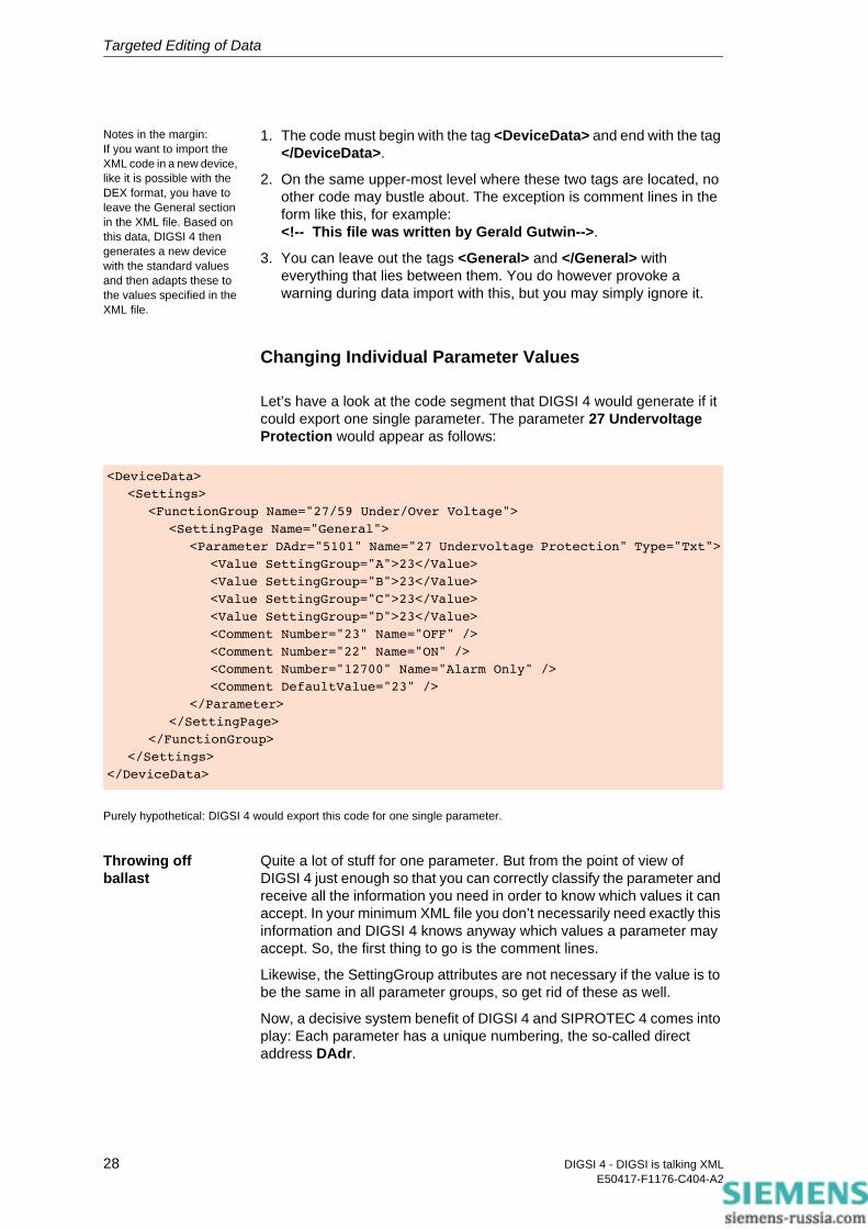
Let’s have a look at the code segment that DIGSI 4 would generate if it could export one single parameter. The parameter 27 Undervoltage Protection would appear as follows:
Purely hypothetical: DIGSI 4 would export this code for one single parameter.
Throwing off ballast
Quite a lot of stuff for one parameter. But from the point of view of DIGSI 4 just enough so that you can correctly classify the parameter and receive all the information you need in order to know which values it can accept. In your minimum XML file you don’t necessarily need exactly this information and DIGSI 4 knows anyway which values a parameter may accept. So, the first thing to go is the comment lines.
Likewise, the SettingGroup attributes are not necessary if the value is to be the same in all parameter groups, so get rid of these as well.
Now, a decisive system benefit of DIGSI 4 and SIPROTEC 4 comes into play: Each parameter has a unique numbering, the so-called direct address DAdr.
<DeviceData>
<Settings>
<FunctionGroup Name="27/59 Under/Over Voltage">
<SettingPage Name="General">
<Parameter DAdr="5101" Name="27 Undervoltage Protection" Type="Txt">
<Value SettingGroup="A">23</Value>
<Value SettingGroup="B">23</Value>
<Value SettingGroup="C">23</Value>
<Value SettingGroup="D">23</Value>
<Comment Number="23" Name="OFF" />
<Comment Number="22" Name="ON" />
<Comment Number="12700" Name="Alarm Only" />
<Comment DefaultValue="23" />
</Parameter>
</SettingPage>
</FunctionGroup>
</Settings>
</DeviceData>
28 DIGSI 4 - DIGSI is talking XMLE50417-F1176-C404-A2
Targeted Editing of Data
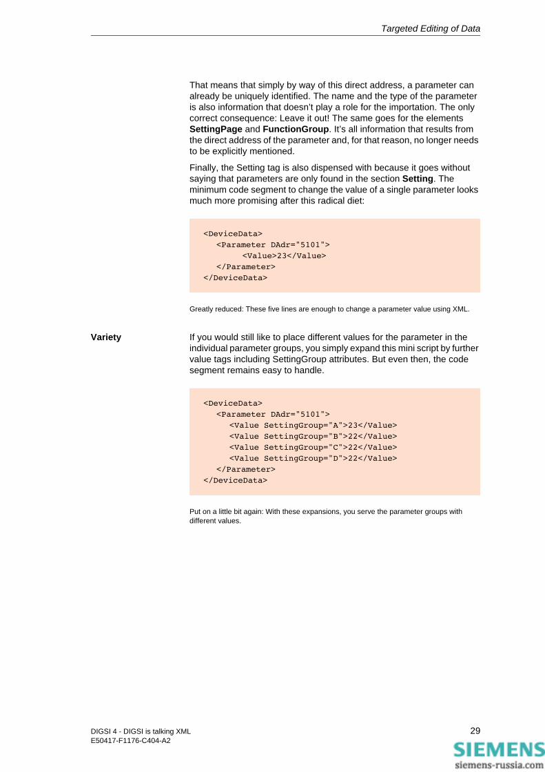
That means that simply by way of this direct address, a parameter can already be uniquely identified. The name and the type of the parameter is also information that doesn’t play a role for the importation. The only correct consequence: Leave it out! The same goes for the elements SettingPage and FunctionGroup. It’s all information that results from the direct address of the parameter and, for that reason, no longer needs to be explicitly mentioned.
Finally, the Setting tag is also dispensed with because it goes without saying that parameters are only found in the section Setting. The minimum code segment to change the value of a single parameter looks much more promising after this radical diet:
Greatly reduced: These five lines are enough to change a parameter value using XML.
Variety If you would still like to place different values for the parameter in the individual parameter groups, you simply expand this mini script by further value tags including SettingGroup attributes. But even then, the code segment remains easy to handle.
Put on a little bit again: With these expansions, you serve the parameter groups with different values.
<DeviceData>
<Parameter DAdr="5101">
<Value>23</Value>
</Parameter>
</DeviceData>
<DeviceData>
<Parameter DAdr="5101">
<Value SettingGroup="A">23</Value>
<Value SettingGroup="B">22</Value>
<Value SettingGroup="C">22</Value>
<Value SettingGroup="D">22</Value>
</Parameter>
</DeviceData>
29DIGSI 4 - DIGSI is talking XMLE50417-F1176-C404-A2
Targeted Editing of Data
Importing an XML Segment
So that this whole thing doesn’t become too dry, we’ll make proof of the matter right away. We’ll generate a 7SJ645, open it once and close it again so that it is ready for the XML import.
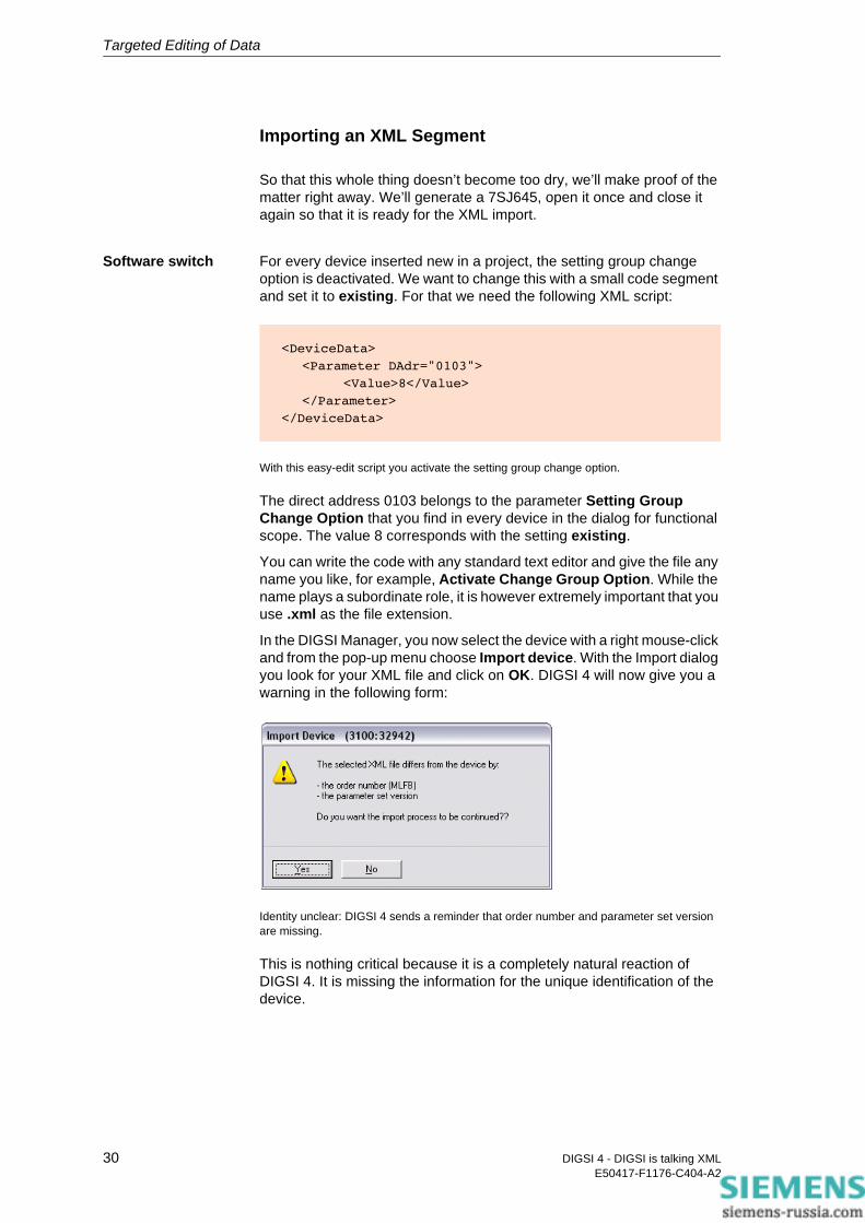
Software switch For every device inserted new in a project, the setting group change option is deactivated. We want to change this with a small code segment and set it to existing. For that we need the following XML script:
With this easy-edit script you activate the setting group change option.
The direct address 0103 belongs to the parameter Setting Group Change Option that you find in every device in the dialog for functional scope. The value 8 corresponds with the setting existing.
You can write the code with any standard text editor and give the file any name you like, for example, Activate Change Group Option. While the name plays a subordinate role, it is however extremely important that you use .xml as the file extension.
In the DIGSI Manager, you now select the device with a right mouse-click and from the pop-up menu choose Import device. With the Import dialog you look for your XML file and click on OK. DIGSI 4 will now give you a warning in the following form:
Identity unclear: DIGSI 4 sends a reminder that order number and parameter set version are missing.
This is nothing critical because it is a completely natural reaction of DIGSI 4. It is missing the information for the unique identification of the device.
<DeviceData>
<Parameter DAdr="0103">
<Value>8</Value>
</Parameter>
</DeviceData>
30 DIGSI 4 - DIGSI is talking XMLE50417-F1176-C404-A2
Targeted Editing of Data
That is why it is making you aware that the data could also belong to another device and therefore might not fit to the selected destination device. You acknowledge this warning with a click on Yes for, after all, you know that the data is compatible with each other.
Convinced DIGSI 4 begins with the import, the progress of which you can once again follow in the Report window. If the import of the data was successful, which we can predict with 100 percent accuracy for our sample task, you still have to explicitly okay that the updated parameter set is really to be stored. This is your last opportunity to prevent the changes. In the current case, you click on Yes without giving it a thought.
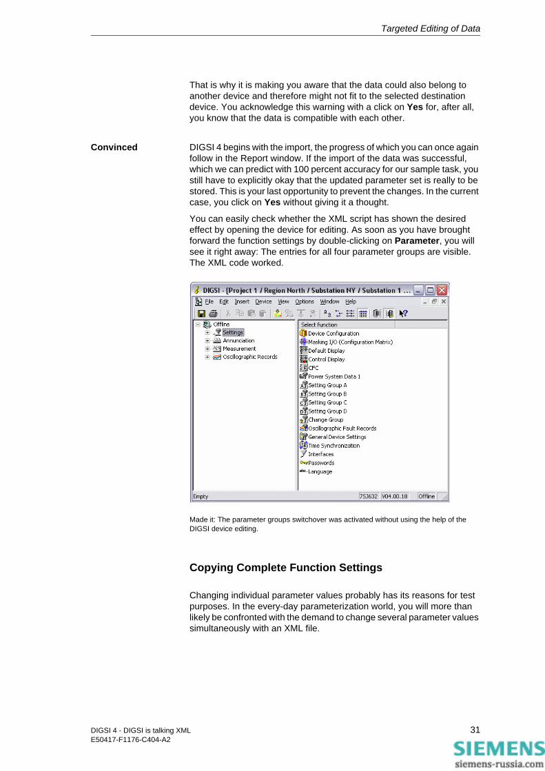
You can easily check whether the XML script has shown the desired effect by opening the device for editing. As soon as you have brought forward the function settings by double-clicking on Parameter, you will see it right away: The entries for all four parameter groups are visible. The XML code worked.
Made it: The parameter groups switchover was activated without using the help of the DIGSI device editing.
Copying Complete Function Settings
Changing individual parameter values probably has its reasons for test purposes. In the every-day parameterization world, you will more than likely be confronted with the demand to change several parameter values simultaneously with an XML file.
31DIGSI 4 - DIGSI is talking XMLE50417-F1176-C404-A2

Targeted Editing of Data
Nothing to argue about. A plausible application would, for example, be to cover all settings of a function with one XML file. In the next figure you see the code for the Time Overcurrent function.
Globetrotter: This code segment feels at home almost everywhere.
The great thing about it: You can import the XML code shown within a device family (such as, 7SA) in devices of different types; the destination device just has to have this function. In principle, you proceed as follows:
1. You export the device data from a specific type in XML.
2. From the export file, you copy the code section that describes the function settings into a new file.
3. You complete the code segment with the tags <DeviceData> at the beginning and </DeviceData> at the end.
4. Optionally, you remove comment lines and other information that is not relevant for the import.
5. You import the file into other device types of a device family.
By the way, it doesn’t matter which national language is set on the destination device. Because as you can see from the code, except for the English language tag names and a comment line, which you could also leave out, it is independent of a specific national language.
Basically, with a script skeleton, you can also copy settings between different device families. Then all you have to do, if its necessary, is change the direct addresses since these don’t necessarily correspond.
<DeviceData>
<!-- Time overcurrent function -->
<Parameter DAdr="1202">
<Value>2.00</Value>
</Parameter>
<Parameter DAdr="1203">
<Value>0.00</Value>
</Parameter>
<Parameter DAdr="1204">
<Value>1.00</Value>
</Parameter>
<Parameter DAdr="1205">
<Value>0.5</Value>
</Parameter>
</DeviceData>
32 DIGSI 4 - DIGSI is talking XMLE50417-F1176-C404-A2
Targeted Editing of Data
Changing Routings and Properties of Existing Information
The highly tooted language independence in setting parameter values is not necessarily given when changing routings and properties of information. That is because not all information in the matrix has a unique identifier that is comparable to the direct address of a parameter. Beyond that, properties of information must fit completely when it has to do with the unique identification based on an address or something similar.
What must be, must be
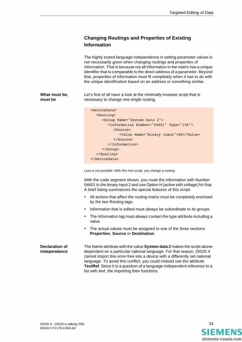
Let’s first of all have a look at the minimally-invasive script that is necessary to change one single routing.
Less is not possible: With this mini script, you change a routing.
With the code segment shown, you route the information with Number 04601 to the binary input 2 and use Option H (active with voltage) for that. A brief listing summarizes the special features of this script:
• All actions that affect the routing matrix must be completely enclosed by the two Routing tags.
• Information that is edited must always be subordinate to its groups.
• The Information tag must always contain the type attribute including a value.
• The actual values must be assigned to one of the three sections Properties, Source or Destination.
Declaration of independance
The Name attribute with the value System data 2 makes the script above dependent on a particular national language. For that reason, DIGSI 4 cannot import this error-free into a device with a differently set national language. To avoid this conflict, you could instead use the attribute TextRef. Since it is a question of a language-independent reference to a list with text, the importing then functions.
<DeviceData>
<Routing>
<Group Name="System Data 2">
<Information Number="04601" Type="106">
<Source>
<Value Name="Binary Input">H2</Value>
</Source>
</Information>
</Group>
</Routing>
</DeviceData>
33DIGSI 4 - DIGSI is talking XMLE50417-F1176-C404-A2
Targeted Editing of Data
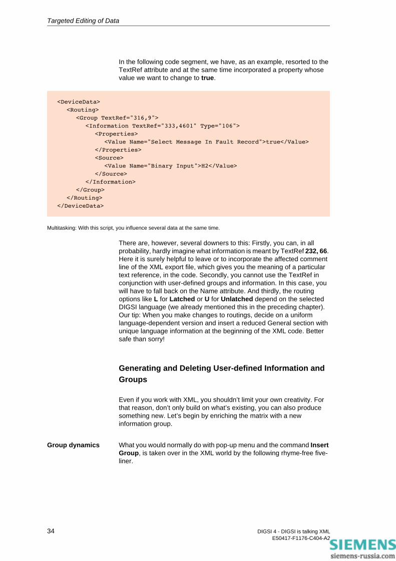
In the following code segment, we have, as an example, resorted to the TextRef attribute and at the same time incorporated a property whose value we want to change to true.
Multitasking: With this script, you influence several data at the same time.
There are, however, several downers to this: Firstly, you can, in all probability, hardly imagine what information is meant by TextRef 232, 66. Here it is surely helpful to leave or to incorporate the affected comment line of the XML export file, which gives you the meaning of a particular text reference, in the code. Secondly, you cannot use the TextRef in conjunction with user-defined groups and information. In this case, you will have to fall back on the Name attribute. And thirdly, the routing options like L for Latched or U for Unlatched depend on the selected DIGSI language (we already mentioned this in the preceding chapter). Our tip: When you make changes to routings, decide on a uniform language-dependent version and insert a reduced General section with unique language information at the beginning of the XML code. Better safe than sorry!
Generating and Deleting User-defined Information and Groups
Even if you work with XML, you shouldn’t limit your own creativity. For that reason, don’t only build on what’s existing, you can also produce something new. Let’s begin by enriching the matrix with a new information group.
Group dynamics What you would normally do with pop-up menu and the command Insert Group, is taken over in the XML world by the following rhyme-free five-liner.
<DeviceData>
<Routing>
<Group TextRef="316,9">
<Information TextRef="333,4601" Type="106">
<Properties>
<Value Name="Select Message In Fault Record">true</Value>
</Properties>
<Source>
<Value Name="Binary Input">H2</Value>
</Source>
</Information>
</Group>
</Routing>
</DeviceData>
34 DIGSI 4 - DIGSI is talking XMLE50417-F1176-C404-A2
Targeted Editing of Data
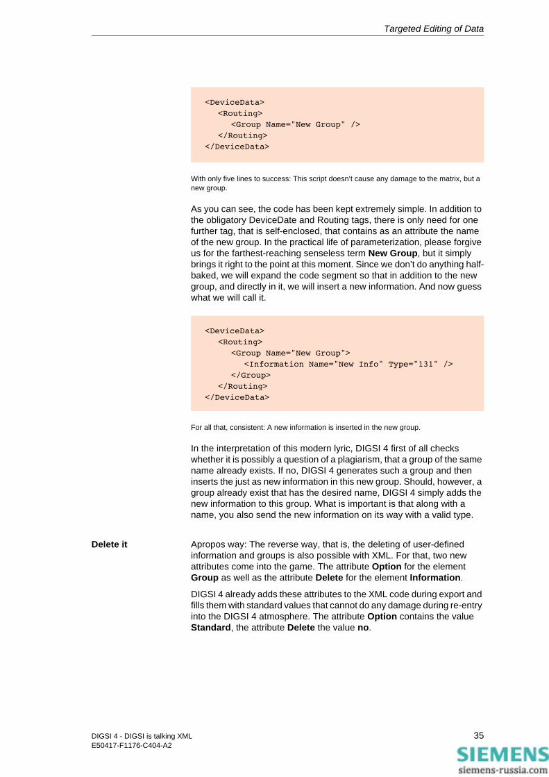
With only five lines to success: This script doesn’t cause any damage to the matrix, but a new group.
As you can see, the code has been kept extremely simple. In addition to the obligatory DeviceDate and Routing tags, there is only need for one further tag, that is self-enclosed, that contains as an attribute the name of the new group. In the practical life of parameterization, please forgive us for the farthest-reaching senseless term New Group, but it simply brings it right to the point at this moment. Since we don’t do anything half-baked, we will expand the code segment so that in addition to the new group, and directly in it, we will insert a new information. And now guess what we will call it.
For all that, consistent: A new information is inserted in the new group.
In the interpretation of this modern lyric, DIGSI 4 first of all checks whether it is possibly a question of a plagiarism, that a group of the same name already exists. If no, DIGSI 4 generates such a group and then inserts the just as new information in this new group. Should, however, a group already exist that has the desired name, DIGSI 4 simply adds the new information to this group. What is important is that along with a name, you also send the new information on its way with a valid type.
Delete it Apropos way: The reverse way, that is, the deleting of user-defined information and groups is also possible with XML. For that, two new attributes come into the game. The attribute Option for the element Group as well as the attribute Delete for the element Information.
DIGSI 4 already adds these attributes to the XML code during export and fills them with standard values that cannot do any damage during re-entry into the DIGSI 4 atmosphere. The attribute Option contains the value Standard, the attribute Delete the value no.
<DeviceData>
<Routing>
<Group Name="New Group" />
</Routing>
</DeviceData>
<DeviceData>
<Routing>
<Group Name="New Group">
<Information Name="New Info" Type="131" />
</Group>
</Routing>
</DeviceData>
35DIGSI 4 - DIGSI is talking XMLE50417-F1176-C404-A2

Targeted Editing of Data
If you want to use the export file to delete some information and groups, you only have to change the values of the attributes concerned. Or, you once again use individual code segments as we will show and describe in the following.
Version 1 You want to specifically delete individual information within a group. For that, you add the attribute Delete with the value yes to the information that is to be deleted.
Individual extinguisher: With this script, you remove specific individual information.
Version 2 You want to delete a group with all the information contained in it. For that, you add the attribute Option with the value DeleteGroup to the group that is to be deleted.
Group extinguisher: With this script, you remove entire groups.
Version 3: You want to specify exactly what the contents of a group are to look like in order to send one or several devices on their way with a kind of basic equipment. For that, you complete the group concerned with the attribute Option with the value Complete. Then, between the Group tags, you list all the information that is to remain of the existing ones or that is to be added.
You do the determining: With this script, you specify the result concretely.
<DeviceData>
<Routing>
<Group Name="New Group">
<Information Name="New Info" Type="131" Delete="yes"/>
</Group>
</Routing>
</DeviceData>
<DeviceData>
<Routing>
<Group Name="New Group" Option="DeleteGroup" />
</Routing>
</DeviceData>
<DeviceData>
<Routing>
<Group Name="New Group" Option="Complete">
<Information Name="New Info" Type="131" />
<Information Name="Another Info" Type="105" />
<Information Name="Existing Info" Type="124" />
</Group>
</Routing>
</DeviceData>
36 DIGSI 4 - DIGSI is talking XMLE50417-F1176-C404-A2

Safety Concept for the XML Import 6In the last chapter you already noticed that DIGSI 4 doesn’t accept what it gets placed before it during the import of XML data without checking it. It immediately recognized and criticized the lack of device-specific features such as the MLFB. In this case, it left the decision to continue with the import with you anyway. First of all, there is no direct danger for the parameter set because of the lack of general device information. And secondly, a rigid attitude by DIGSI 4 at this point would make it impossible to write XML scripts that are to be used by different devices. But as soon as there is danger ahead, DIGSI 4 intervenes uncompromisingly - for the safety of the parameter set.
Threefold is just better
The safety concept for the importing of data in the XML format is three-stage: After a device validation, there follows a syntax check and then a plausibility control of all parameters, routings and values.
Device Validation
In the first step, DIGSI 4 compares the information on the device that it finds under the XML node General with that in the parameter set. Let’s bring back to mind which general device data DIGSI 4 inserts in the XML file during export.
Program repetition: Here once more the general device data.
<General>
<GeneralData Name="DIGSI" ID="4.80.31.995" />
<GeneralData Name="Name" ID="7SJ632" />
<GeneralData Name="Topology" ID="Project 1 / Region North / Substat ..." />
<GeneralData Name="Version" ID="V4.0.18" />
<GeneralData Name="MLFBDIGSI" ID="7SJ63212BC313FH3" />
<GeneralData Name="VDAdr" ID="1031" />
<GeneralData Name="DeviceLanguage" ID="C" Language="English (US)" />
<GeneralData Name="DIGSILanguage" ID="C" Language="English (US)" />
</General>
37DIGSI 4 - DIGSI is talking XMLE50417-F1176-C404-A2

Safety Concept for the XML Import
Opinion poll If this information is now different or the node doesn’t even exist, you will get at least one or even several warnings. The first of these you already know:
Already known: The identity of the device cannot be clarified.
If you acknowledge this warning with a click on Yes, DIGSI 4 will probably show you a second warning and then always when the following two prerequisites are fulfilled at the same time:
• Both attributes DeviceLanguage and DIGSILanguage are missing and with that the reference to a specific national language.
• The XML file contains changes to the routing.
Your opinion is asked for once more.
Conclusions The two prerequisites mentioned above mean that this message will never appear as long as you only want to influence parameter values with the XML file. This is because language-dependent additions of a parameter like its name are always ignored during import; after all, the direct address is sufficient for identification.
With routings it is different. Information and groups can to a certain extent also be language-independently recognized by means of the attribute TextRef. In many cases, though, a language-dependent identification is necessary, such as for user-defined groups and information or the abbreviations of routing options. For that reason, DIGSI 4 always draws your attention to possible incompatibilities.
38 DIGSI 4 - DIGSI is talking XMLE50417-F1176-C404-A2
Safety Concept for the XML Import
Your responses to this warning should therefore be as follows. If there are no language-dependent identifiers in your XML file, ignore the message and click on Yes. If this is not so, you should first of all check whether the language set in the device is the same as that used for the names in the XML file.
If for some reason you don’t make the right decision at some point in time and you still click on Yes, nothing earth-shattering is going to happen. DIGSI 4 will generate a message in the Report window for every incompatibility and will not adopt the data in the parameter set. If the import is then completed, you still have the opportunity to forego a definitive saving of the temporarily changed parameter set.
Wishful thinking Just a word on the specification of the language. DIGSI 4 analyzes exclusively the two IDs and ignores the value of the attribute Language. The wish for dialects like in the following script will hence remain a wish.
Unfortunately stands way down on the list of features still to be implemented.
Syntax Check
Provided that DIGSI 4 had no reason for concern during the device validation or you confirmed all occurring warnings with Yes, we now enter the second phase of the import.
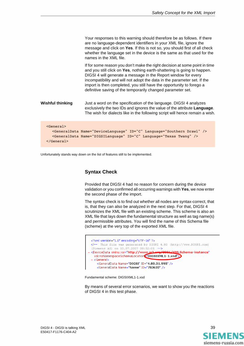
The syntax check is to find out whether all nodes are syntax-correct, that is, that they can also be analyzed in the next step. For that, DIGSI 4 scrutinizes the XML file with an existing scheme. This scheme is also an XML file that lays down the fundamental structure as well as tag name(s) and permissible attributes. You will find the name of this Schema file (scheme) at the very top of the exported XML file.
Fundamental scheme: DIGSIXML1-1.xsd
By means of several error scenarios, we want to show you the reactions of DIGSI 4 in this test phase.
<General>
<GeneralData Name="DeviceLanguage" ID="C" Language="Southern Drawl" />
<GeneralData Name="DIGSILanguage" ID="C" Language="Texas Twang" />
</General>
39DIGSI 4 - DIGSI is talking XMLE50417-F1176-C404-A2
Safety Concept for the XML Import
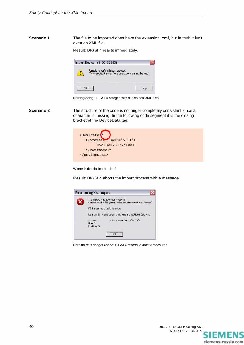
Scenario 1 The file to be imported does have the extension .xml, but in truth it isn’t even an XML file.
Result: DIGSI 4 reacts immediately.
Nothing doing!: DIGSI 4 categorically rejects non-XML files.
Scenario 2 The structure of the code is no longer completely consistent since a character is missing. In the following code segment it is the closing bracket of the DeviceData tag.
Where is the closing bracket?
Result: DIGSI 4 aborts the import process with a message.
Here there is danger ahead: DIGSI 4 resorts to drastic measures.
<DeviceData
<Parameter DAdr="5101">
<Value>23</Value>
</Parameter>
</DeviceData>
40 DIGSI 4 - DIGSI is talking XMLE50417-F1176-C404-A2

Safety Concept for the XML Import
Scenario 3 A tag name was written incorrectly, as is easily recognized in the following code segment.
Well what do you know: Measuring unit instead of made to measure.
Since this type of error does not destroy the structure of the XML code, but merely makes one individual node unusable, DIGSI 4 sends you a message but leaves the decision to abort or continue with you.
Listen to your inner voice and don’t take any risks.
Our tip: Even if the parameter set isn’t damaged later on since DIGSI 4 simply ignores such nodes, you should abort the import and eliminate the error in the XML file.
Scenario 4 You swap individual nodes in the sequence.
Result: As long as you don’t damage the fundamental XML structure in the process, DIGSI 4 has no objections.
Plausibility Control
With the plausibility control, we reach the third and last step of the integrity test. In this phase, DIGSI 4 assigns the values from the XML file node for node to the corresponding parameters in the parameter set. However, DIGSI 4 only does this when the values lie within the validity range.
It ignores all invalid values and generates concrete messages in the Report window for them. For the plausibility check as well, we will once again supply you with some thoroughly realistic error scenarios.
<DeviceData>
<ParaCentimeter DAdr="5101">
<Value>23</Value>
</Parameter>
</DeviceData>
41DIGSI 4 - DIGSI is talking XMLE50417-F1176-C404-A2
Safety Concept for the XML Import
Scenario 1 To save work, you copy a complete parameter node. You edit the value but forget to change the direct address. This is now found twice in the code.
Result: Different than in real life, Number 2 wins here. That means, DIGSI 4 first of all imports the value that lies in the first position in the sequence for the parameter concerned and then overwrites it with the value in the second position. In this case, you don’t get an error message.
Scenario 2 You change the direct address of a parameter, but you don’t get the result you want.
Result: Here we have to differentiate between two cases. In the first case, a direct address that doesn’t exist results from an incorrect entry. DIGSI 4 simply ignores this without further warnings. In the second case, a direct address emerges that in fact already exists for another parameter. Since DIGSI 4 cannot know that you have specified the correct address incorrectly, it imports the associated value in so far as it lies within the validity range.
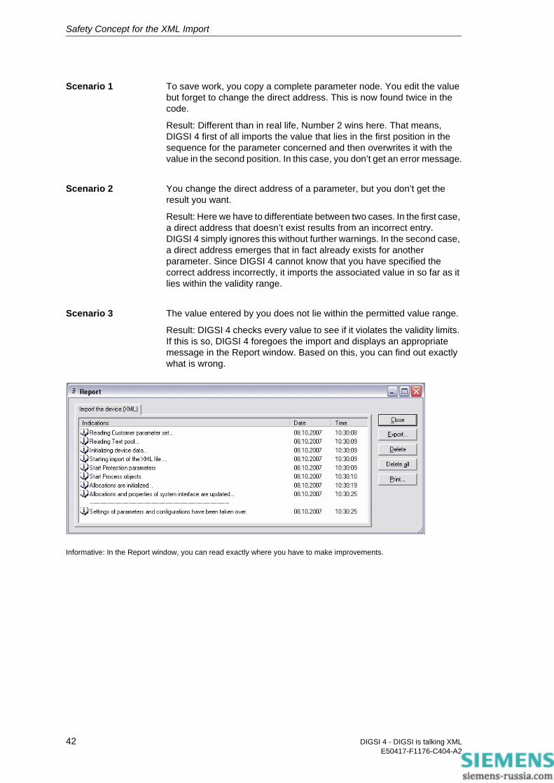
Scenario 3 The value entered by you does not lie within the permitted value range.
Result: DIGSI 4 checks every value to see if it violates the validity limits. If this is so, DIGSI 4 foregoes the import and displays an appropriate message in the Report window. Based on this, you can find out exactly what is wrong.
Informative: In the Report window, you can read exactly where you have to make improvements.
42 DIGSI 4 - DIGSI is talking XMLE50417-F1176-C404-A2

Excel as Data Source 7Experience shows that often several protecting devices are fed with the same or at least almost the same parameter values. It is therefore absolutely worthwhile and even economically justifiable to clearly prepare the individual setting values before the actual parameterization. That way the individual values can be reviewed in their entirety and also be controlled for plausibility more easily.
Manual labor: An example of a self-created setting sheet.
Calculating For many users, and possibly even you, a spread-sheet calculation program is the software that is suitable for this. With the usually numerous formatting possibilities, so-called setting sheets can be custom-designed. There are hardly any limits on creativity here. Whereby, the design alone, however, is not the deciding factor. After all, many setting values don’t just appear out of the blue, but are the result of often elaborate calculations. Spread-sheets already have their advantage anchored in the name, namely that they can carry out calculations and, that they already bring the necessary tools for this with them.
43DIGSI 4 - DIGSI is talking XMLE50417-F1176-C404-A2
Excel as Data Source
dapt and
Such setting sheets could then not only contain the pure setting data but also, for example, the complete distance protection calculations for it. In additional tables, you store line section and relay data that you need for the calculations and you derive new parameter values from existing ones using suitable formulas. Additional notes then complete the whole thing to make it an informative and valuable setting portfolio.
The advantage is obvious but up until now there was also a big disadvantage: In order to get the values gathered in the setting sheets into the protective setting program there was practically only one solution up until now: to type it! That is not only time-consuming but also prone to errors.
But typing is now a thing of the past for all users of DIGSI as of Version 4.8, at least if their spread-sheet answers to the name of Excel. For this, Siemens provides you with a free add-in that takes this work off your hands in a few seconds using XML Export and that actively supports you in the creation of new and the adapting of existing setting sheets.
Installing the Add-In
You will find the add-in as of Version 4.81 on the DIGSI 4 installation CD. If you can’t call this your own, then simply get the Excel addition via the Internet. In the SIPROTEC Download Area, that you reach with the URL www.siprotec.de, you will find it under the link Programs → DIGSI 4.
Drop landing The add-in lands on your hard drive in the form of a self-extracting ZIP archive, that is, as EXE file. A double-click on the file name unzips the add-in along with two text files, one each for German and English. Copy the add-in file DIGSI XML Interface.xla in the add-in directory of your Windows installation. This is usually C:\Documents and Settings\User\Application Data\Microsoft\AddIns.
Start Excel. In the menubar you should now find the additional new entry DIGSI. If not, the reason may be your Excel version. In Excel 2003, then open the Add-In Manager with Options → Add-Ins. Activate the control field next to the entry DIGSI XML Interface. After a click on OK and a short pause, Excel should display the new menu name. With Excel 2007, first of all open the setup window using the Office menu > Excel Options, then call up the Add-In page via "Add-Ins" in the menu on the left. Select the "Excel Add-Ins" from the “Manage“ drop-down and "Go". With the Add-In Manager you can of course deactivate the add-in at any time in the reverse manner.
The first menu entry right away shows the essence and purpose of the add-in: with Export settings to XML it converts the settings from the opened EXCEL table into DIGSI XML code and thus saves you a lot of typing. For this, however, the table must fulfill several requirements.
3-course menu: Create, a
export.
44 DIGSI 4 - DIGSI is talking XMLE50417-F1176-C404-A2
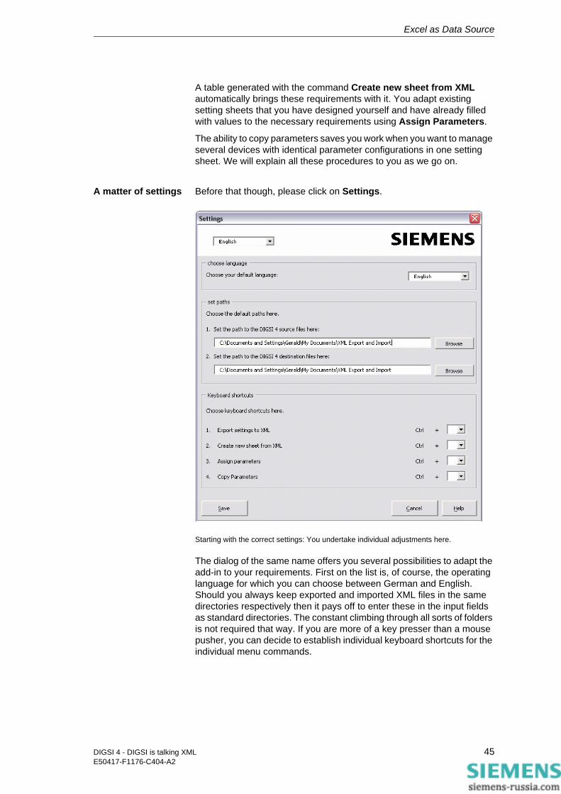
Excel as Data Source
A table generated with the command Create new sheet from XML automatically brings these requirements with it. You adapt existing setting sheets that you have designed yourself and have already filled with values to the necessary requirements using Assign Parameters.
The ability to copy parameters saves you work when you want to manage several devices with identical parameter configurations in one setting sheet. We will explain all these procedures to you as we go on.
A matter of settings Before that though, please click on Settings.
Starting with the correct settings: You undertake individual adjustments here.
The dialog of the same name offers you several possibilities to adapt the add-in to your requirements. First on the list is, of course, the operating language for which you can choose between German and English. Should you always keep exported and imported XML files in the same directories respectively then it pays off to enter these in the input fields as standard directories. The constant climbing through all sorts of folders is not required that way. If you are more of a key presser than a mouse pusher, you can decide to establish individual keyboard shortcuts for the individual menu commands.
45DIGSI 4 - DIGSI is talking XMLE50417-F1176-C404-A2

Excel as Data Source
Creating and Editing a New Setting Sheet
Let’s first of all assume that you haven’t as yet created any of your own setting sheets but would like to have one generated by the add-in. No problem! With a few mouse-clicks you’ll get one. And before we explain to you which mouse-clicks are involved let’s have a look at the result.
Well done: The setting sheet generated by the Excel add-in contains all possible settings.
Old acquaintances After a brief look you will quickly notice that what you see looks familiar to you. After all, it is a question of parameter names that you already know from the work with the DIGSI Device Editor. These are structured according to the entries in the operator tree as well as according to the names of the dialogs and the dialog tabs that you also know. And even the comfort doesn’t break down. Selection parameters that, in the DIGSI dialog, bring all of your permissible settings to light as a list with the press of a button also do this in the setting sheet. With input parameters, however, information to the right of the input area shows you the permitted value limits. The add-in also checks after a value has been entered whether you have taken these limits into account and criticizes, with a message, if you are off the mark.
That the add-in still accepts a value that is outside of the validity range is, by the way, no error but has been consciously planned. After all, you should stay flexible and also be able use parts of the setting sheet for other devices for which the validity ranges could very well be different.
46 DIGSI 4 - DIGSI is talking XMLE50417-F1176-C404-A2
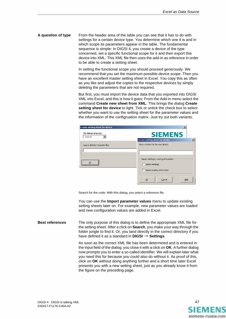
Excel as Data Source
A question of type From the header area of the table you can see that it has to do with settings for a certain device type. You determine which one it is and in which scope its parameters appear in the table. The fundamental sequence is simple: In DIGSI 4, you create a device of the type concerned, set a specific functional scope for it and then export this device into XML. This XML file then uses the add-in as reference in order to be able to create a setting sheet.
In setting the functional scope you should proceed generously. We recommend that you set the maximum possible device scope. Then you have an excellent master setting sheet in Excel. You copy this as often as you like and adjust the copies to the respective devices by simply deleting the parameters that are not required.
But first, you must import the device data that you exported into DIGSI XML into Excel, and this is how it goes: From the Add-in menu select the command Create new sheet from XML. This brings the dialog Create setting sheet for device to light. Tick or untick the check box to select whether you want to use the setting sheet for the parameter values and the information of the configruation matrix. Just try out both variants.
Search for the code: With this dialog, you select a reference file.
You can use the Import parameter values menu to update existing setting sheets later on. For example, new parameter values are loaded and new configuration values are added in Excel.
Best references The only purpose of this dialog is to define the appropriate XML file for the setting sheet. After a click on Search, you make your way through the folder jungle to find it. Or, you land directly in the correct directory if you have defined it as a standard in DIGSI → Settings.
As soon as the correct XML file has been determined and is entered in the input field of the dialog, you close it with a click on OK. A further dialog now prompts you to enter a so-called identifier. We will explain later what you need this for because you could also do without it. As proof of this, click on OK without doing anything further and a short time later Excel presents you with a new setting sheet, just as you already know it from the figure on the preceding page.
47DIGSI 4 - DIGSI is talking XMLE50417-F1176-C404-A2
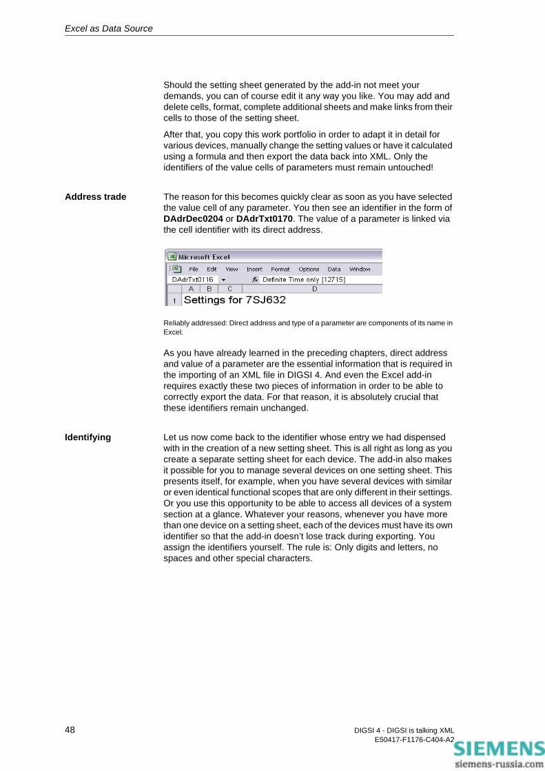
Excel as Data Source
Should the setting sheet generated by the add-in not meet your demands, you can of course edit it any way you like. You may add and delete cells, format, complete additional sheets and make links from their cells to those of the setting sheet.
After that, you copy this work portfolio in order to adapt it in detail for various devices, manually change the setting values or have it calculated using a formula and then export the data back into XML. Only the identifiers of the value cells of parameters must remain untouched!
Address trade The reason for this becomes quickly clear as soon as you have selected the value cell of any parameter. You then see an identifier in the form of DAdrDec0204 or DAdrTxt0170. The value of a parameter is linked via the cell identifier with its direct address.
Reliably addressed: Direct address and type of a parameter are components of its name in Excel.
As you have already learned in the preceding chapters, direct address and value of a parameter are the essential information that is required in the importing of an XML file in DIGSI 4. And even the Excel add-in requires exactly these two pieces of information in order to be able to correctly export the data. For that reason, it is absolutely crucial that these identifiers remain unchanged.
Identifying Let us now come back to the identifier whose entry we had dispensed with in the creation of a new setting sheet. This is all right as long as you create a separate setting sheet for each device. The add-in also makes it possible for you to manage several devices on one setting sheet. This presents itself, for example, when you have several devices with similar or even identical functional scopes that are only different in their settings. Or you use this opportunity to be able to access all devices of a system section at a glance. Whatever your reasons, whenever you have more than one device on a setting sheet, each of the devices must have its own identifier so that the add-in doesn’t lose track during exporting. You assign the identifiers yourself. The rule is: Only digits and letters, no spaces and other special characters.
48 DIGSI 4 - DIGSI is talking XMLE50417-F1176-C404-A2

Excel as Data Source
Copying Parameters
Now the only thing that has to be clarified is how you get the data of several devices onto one common setting sheet. For that, you first of all create a new setting sheet once again, (almost) like we described it further above. In the query for an identifier, you don’t simply click on this time, instead you enter a valid character combination. We have done this as well and selected E01 as the identifier.
At first glance, the new setting sheet appears no different that its predecessor. If, however, you look at the name of a value cell, you will see that the previous character sequence has been supplemented by the identifier assigned by you or us. This now looks like this, for example: DAdrDec_E01_0204.
Intermediate course
To complete the existing setting sheet with the data of another device, copy the data of the already existing device to another place in the table. However, please don’t use the usual copy/paste procedure. With that you would certainly copy the contents, however all cell identifiers would collapse. (You would have the soup without the bowl and how would you ever be able to spoon it out?) Reach for the DIGSI menu instead. For between the three courses Create - Adapt - Export there was still room for an intermediate course with the name Copy Parameter. We will show how you deal with it using an example.
First of all, you expand the newly generated setting sheet by an additional column which you place between the information on physical units and validity ranges. After that, you select all value cells in the column F and then choose the command Copy Parameters.
49DIGSI 4 - DIGSI is talking XMLE50417-F1176-C404-A2

Excel as Data Source
Good copy: Always use the add-in function Copy Parameters.
In the dialog Copy Parameters you define the destination area of the data. To do so, you merely select the upper-most cell of the destination area in the setting sheet. In our case, it is the cell in the newly inserted column that is located at the same height as the first value cell. With alternating clicks on Show new and Show old you ascertain that you really chose the correct starting cell. Only then are the selected areas located parallel to one another. If everything is in order here, click Ready.
In the next dialog box, that you now are already familiar with, you enter the identifier for the second device, for example E02. As you can see, the input field is a list at the same time. You can therefore also add data to a device after the fact and then select the associated identifier from this list. Then click on OK. The add-in inserts the copied data into the area defined for this. Crucial nevertheless is that the names of the value cells now contain the identifier E02 guaranteeing the possibility of differentiating between the two devices.
Cosmetic surgery So that the clarity is also retained, you should give the new column the optimum width and highlight the individual cells in color. It is also recommended that you copy the column with the physical units. You can see the complete result in the following figure.
50 DIGSI 4 - DIGSI is talking XMLE50417-F1176-C404-A2

Excel as Data Source
No problem for the add-in: To manage the data of two or more devices in one setting sheet.
Routing You have certainly imported the configurations when you created the new setting sheet. It is not recommended to include information on parameters and configurations in the same Excel sheet. It is therefore better to go to the “Routing“ sheet. The overall result can be seen in the figure below.
51DIGSI 4 - DIGSI is talking XMLE50417-F1176-C404-A2

Excel as Data Source
Routings in a different way.
This is the complete Routingmatrix. The table with the Routingmatrix may appear very familiar to you. In fact, it is very similar to the short view in DIGSI. However, this means for you that you are not allowed to make any structural changes in the table. The essential difference to the DIGSI matrix is that there is only one matrix for commands and measured values. The colour of the cells indicates where entries are possible and where not. Possible values are displayed in selection boxes. The Routing submenu offers functions for adding new groups and indications to the configuration matrix. These are similar to those you may know from DIGSI. Just try it out.
52 DIGSI 4 - DIGSI is talking XMLE50417-F1176-C404-A2

Excel as Data Source
Exporting the Setting Data in XML Code and Importing It in DIGSI
The exporting of data is just as easy as the importing, but it offers a number of additional possibilities to influence the scope of the exported data. First of all, you have the choice of earmarking the complete table for the export, or to make a preselection.
For the second variant, you select an area that is intended for the export. Such an area consists of only one parameter in the simplest case.
Out of here With DIGSI → Export settings to XML now open the export dialog of the add-in. You can also tick or untick the check boxes to select whether you want to export the information of the parameter values and the configuration matrix. In the bottom half of this dialog you now have further possibilities to have an influence on the data scope. If you previously selected a table area, the option Selection is active and also selected. You can, however, still decide differently and choose the option Whole table.
Now it goes out: The export dialog of the add-in.
If you manage the settings of several devices on one setting sheet and have properly differentiated them with identifiers, you can further restrict the scope of the exported data.
53DIGSI 4 - DIGSI is talking XMLE50417-F1176-C404-A2
Excel as Data Source
For that, you choose the identifier of a device from the respective list if the add-in is only to export its data. Or, you select the setting All and in that way make sure that the add-in generates a separate XML file for every device.
Before that, however, probably the most important input is missing, namely the destination and the name of the export file. Here it is just like importing: One click on Search leads you directly to the desired directory if everything is optimally prepared or, in the worst case, lets you roam about in the folder nirvana.
No risk If you want to be on the safe side that all your settings are within the permitted ranges, then make use of the comparison function of the XML export. For that, the add-in requires a reference file, that is, an XML file of the same device type exported from DIGSI 4. For each parameter, the add-in individually compares its setting with the permissible settings that are stored in the comment lines of the respective parameter in the reference file. As soon as the add-in determines a discrepancy, it interrupts the export, opens a text file in which the difference is explained and asks you whether you want to continue with the export or whether it should be ended.
To use the comparison function, first of all select the control field in the section Checking. Then, choose the reference file. If possible, use the file on whose basis you have already created the setting sheet.
But now ... Now finally, click on OK to close the dialog and to start the export. It gets into gear quickly and usually only takes one, two seconds. And there you have the file(s) ready to access in the destination directory so that they can be imported into the DIGSI Manager in one or more devices. You already learned how this works in Chapter 3.
Just one more note on the import mechanisms of DIGSI 4: Should there be errors in the exported XML code, either because of the lack of an activated comparison function or because you have knowingly accepted it, DIGSI 4 stubbornly strikes back. DIGSI 4 mercilessly sorts out parameters or values that are not compatible, for only in that way is the data consistency of a parameter set ensured.
Experimental time killing
By the way, the fact that a difference exists between what goes in the front and what comes out the back, even if you haven’t knowingly changed anything along the way, can be illustrated by the following little experiment: Import the data of an XML file in Excel and then export it again immediately without doing anything in between. From the file sizes alone you will notice the file exported out of Excel is a lot slimmer than the original XML file. One glance at the insides will then divulge why this is so. The add-in only exports that which is absolutely necessary for the import into DIGSI 4. And that is simply the direct address and the value of each individual parameter.
The rest of the information on the parameter such as its type or name have disappeared, just as the comment lines with the possible settings as well as the division according to functional aspects.
54 DIGSI 4 - DIGSI is talking XMLE50417-F1176-C404-A2
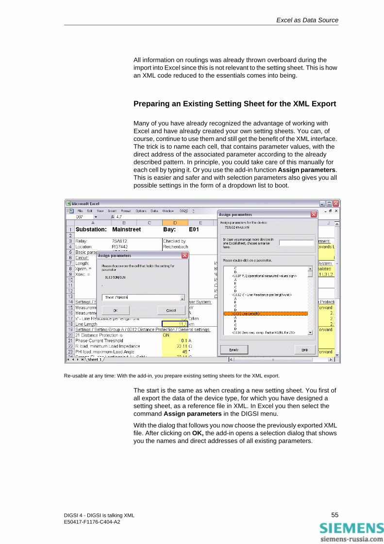
Excel as Data Source
All information on routings was already thrown overboard during the import into Excel since this is not relevant to the setting sheet. This is how an XML code reduced to the essentials comes into being.
Preparing an Existing Setting Sheet for the XML Export
Many of you have already recognized the advantage of working with Excel and have already created your own setting sheets. You can, of course, continue to use them and still get the benefit of the XML interface. The trick is to name each cell, that contains parameter values, with the direct address of the associated parameter according to the already described pattern. In principle, you could take care of this manually for each cell by typing it. Or you use the add-in function Assign parameters. This is easier and safer and with selection parameters also gives you all possible settings in the form of a dropdown list to boot.
Re-usable at any time: With the add-in, you prepare existing setting sheets for the XML export.
The start is the same as when creating a new setting sheet. You first of all export the data of the device type, for which you have designed a setting sheet, as a reference file in XML. In Excel you then select the command Assign parameters in the DIGSI menu.
With the dialog that follows you now choose the previously exported XML file. After clicking on OK, the add-in opens a selection dialog that shows you the names and direct addresses of all existing parameters.
55DIGSI 4 - DIGSI is talking XMLE50417-F1176-C404-A2
Excel as Data Source
The assignment now works quite simply: You double-click on a parameter and enter the cell coordinates in a second dialog box. This is done either manually or - much easier - by selecting the associated cell in your setting sheet using a mouse-click. A click on OK and the assignment for the first parameter is perfect. You proceed similarly for the other parameters. It’s no problem here, as well, if you manage several devices with one setting sheet.
To make the devices distinguishable for the export, enter identifiers for the individual devices in the upper-right of the input field. An identifier that you’ve entered remains valid until you enter a new identifier.
Special Case: Adopting Settings from Analog Siemens Protective Gear
Let’s assume you would like to replace an older, still electromechanical SIPROTEC device from analog times with a current digital one. You have documented the protection settings of the older device and want to transfer this into the new device with the least amount of effort. Even this task doesn’t present a problem because you solve it in a few steps using a macro developed for this and the associated setting sheet. In it, you enter the existing protection settings, let them be exported to XML using an integrated macro and then import them into a current DIGSI 4 project.
Two pairs of boots The following explanations have nothing more to do with the Excel add-in, by the way, and are therefore identified in the title as a special case. Setting sheet and macro are installed with DIGSI 4. You open it directly via the Start menu of Windows. There you will find in the folder Siemens Energy → DIGSI the entry Import analog device settings. With this you start Excel and the setting sheet. Before this appears though, a dialog box first appears. Here you choose the type of the prevailing analog device. If necessary, you select one of the two other options if they apply to the functional scope of the device. In the lower part of the dialog, you can then already see the almost complete MLFB of the future device. As soon as you click on Next, Excel displays the worksheet with already preassigned values (see next page).
You now have to adapt all values in the yellow hi-lighted fields to the prevailing protections settings. Here as well, you have dropdown lists to select a setting for the selection parameters for which only very particular values are permitted. When you’ve done everything, click on Export XML File and then as usual define the destination and the name for the export file.
In DIGSI 4, you now open a project and in it you insert a device with the applicable MLFB. Select this device and from the pop-up menu choose the command Import device. In the dialog that appears, select XML as the import format and then the previously exported file with protection settings. DIGSI 4 now adopts the protection settings in the SIPROTEC 4 device. That’s it!
56 DIGSI 4 - DIGSI is talking XMLE50417-F1176-C404-A2
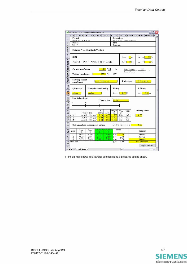
Excel as Data Source
From old make new: You transfer settings using a prepared setting sheet.
57DIGSI 4 - DIGSI is talking XMLE50417-F1176-C404-A2
Excel as Data Source
58 DIGSI 4 - DIGSI is talking XMLE50417-F1176-C404-A2
Exchanging Data with Applications from the Power Distribution Area 8
With Excel, you exchange data actually only within your own four walls. But as soon as you leave these, you see a series of other interesting applications:
• Line calculation
• Protection test
• Line and protective data management.
Most of these have been around for awhile, now with DIGSI XML you also have a smooth data exchange free-of-charge as well.
In the development and optimization of the DIGSI XML interface, Siemens worked very closely with the suppliers of the applications described: OMICRON, IPS, DIgSILENT and Electrocon are only some of them. All profit from this cooperation, most of all you. For where you previously had to exchange the data manually by typing it, you now do it with XML.
Here now a really brief overview. You can find out detailed information on the individual products as well as the cooperation between Siemens and the individual manufacturers directly from them.
Line Calculation
With line calculation programs, users simulate different fault situations and based on the results determine the necessary setting data for the protective device. Professional programs such as SINCAL and SIGRADE from Siemens, PowerFactor from DIgSILENT or CAPE from Electrocon automatically supply setting recommendations.
Up until now you had to print these out in order to then retype them in DIGSI 4. All programs mentioned now offer an interface compatible to DIGSI XML. For you it means: You export this data into an XML file and import the data of this file into DIGSI 4.
59DIGSI 4 - DIGSI is talking XMLE50417-F1176-C404-A2
Exchanging Data with Applications from the Power Distribution Area
Protection Test
The OMICRON Company has further developed its RIO format to the XML-based XRIO format. This format that OMICRON has introduced with the Test-universe 2.0, now separates parameters from the actual functional implementation.
Even DIGSI as of Version 4.8 masters this format. With that, Siemens is the first manufacturer that actively supports the new XRIO format. And you can now export the protective settings of each SIPROTEC 4 device in the XRIO format.
OMICRON provides free-of-charge XRIO converters for the Testuniverse 2.0, with which you can very easily import the setting values and thus efficiently create the test program.
Line and Protective Data Management
Already one single Siemens protective device contains a large number of parameters with the associated settings. So as not to lose the overview with the diversity of devices within a system, you’re best bet is a program for line and protective data management. You transfer the data there using XML and so receive a common data collection for all devices. As an additional benefit, it enables you to optimize and analyze data. Examples of such programs are TestBase from OMICRON, IPS-Energy RELEX from IPS and StationWare from DIgSILENT.
60 DIGSI 4 - DIGSI is talking XMLE50417-F1176-C404-A2

What Else You Should Know 9The following tables show you the assignment of the Info numbers to the individual information.
Indications Info number
Single Point
Event (SP_Ev) 105
ON/OFF (SP) 106
Open/Close (SP) 107
external Single Point ON/OFF (ExSP) 134
external Single Point Open/Close (ExSP) 135
Single Point FAST
Protection Single Point Fast ON/OFF 129
Protection Single Point Fast Open/Close 130
Double Point
0= not valid (DP) 108
0= intermediate (DP_I) 109
external double indication (ExDI) 151
external double indication (ExDI_S) 150
Output SLOW
Event (Out_Ev) 123
ON/OFF (Out) 124
Open/Close (Out) 125
Value Indication (VI) 156
Output FAST
Protection ON/OFF (Out) 131
Protection Open/Close (Out) 132
61DIGSI 4 - DIGSI is talking XMLE50417-F1176-C404-A2
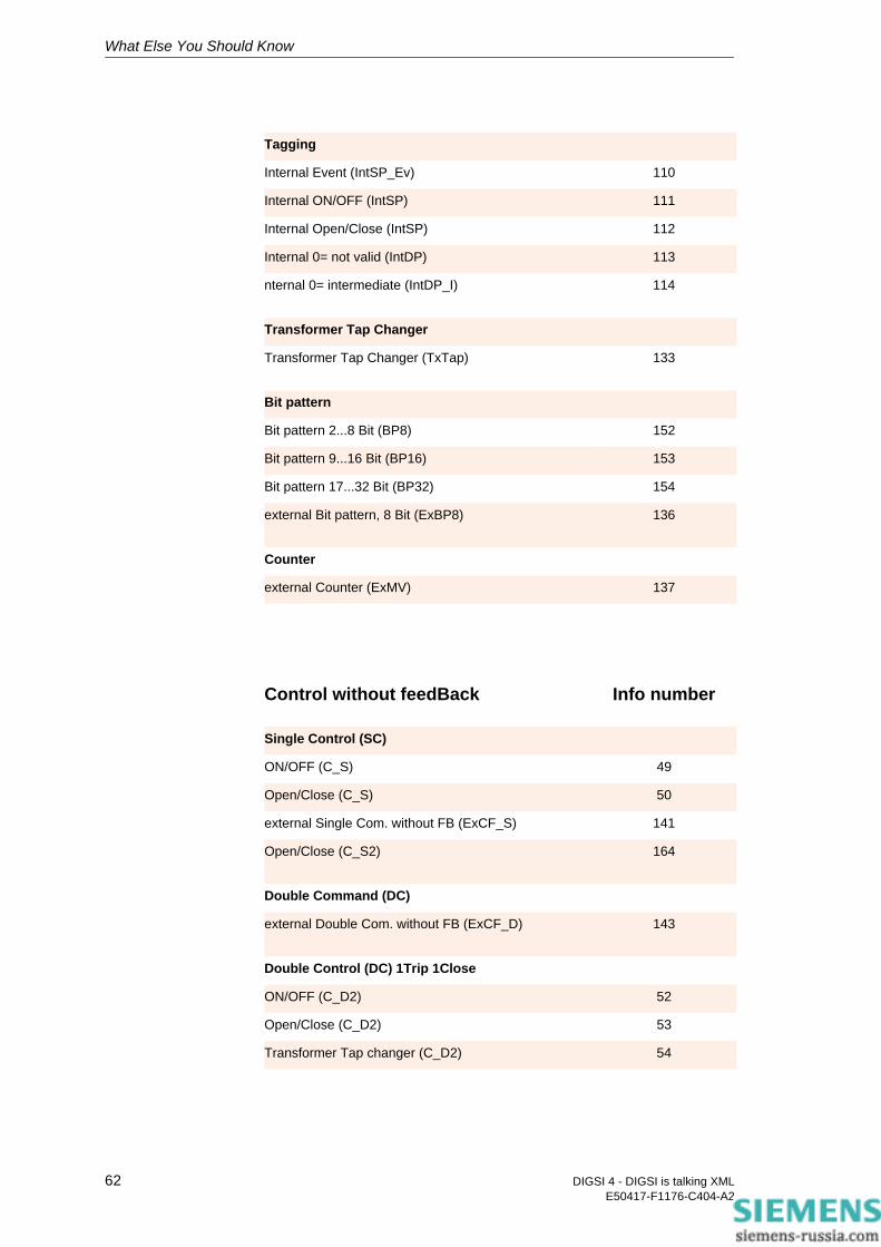
What Else You Should Know
Tagging
Internal Event (IntSP_Ev) 110
Internal ON/OFF (IntSP) 111
Internal Open/Close (IntSP) 112
Internal 0= not valid (IntDP) 113
nternal 0= intermediate (IntDP_I) 114
Transformer Tap Changer
Transformer Tap Changer (TxTap) 133
Bit pattern
Bit pattern 2...8 Bit (BP8) 152
Bit pattern 9...16 Bit (BP16) 153
Bit pattern 17...32 Bit (BP32) 154
external Bit pattern, 8 Bit (ExBP8) 136
Counter
external Counter (ExMV) 137
Control without feedBack Info number
Single Control (SC)
ON/OFF (C_S) 49
Open/Close (C_S) 50
external Single Com. without FB (ExCF_S) 141
Open/Close (C_S2) 164
Double Command (DC)
external Double Com. without FB (ExCF_D) 143
Double Control (DC) 1Trip 1Close
ON/OFF (C_D2) 52
Open/Close (C_D2) 53
Transformer Tap changer (C_D2) 54
62 DIGSI 4 - DIGSI is talking XMLE50417-F1176-C404-A2

What Else You Should Know
Double Control (DC) 1Trip 1Close 1Com
ON/OFF (C_D3) 55
Open/Close (C_D3) 56
Transformer Tap changer (C_D3) 57
Double Control (DC) 2Trip 2Close
ON/OFF (C_D4) 58
Open/Close (C_D4) 59
Transformer Tap changer (C_D4) 60
Open/Close (C_D22) 166
Double Control (DC) 1Trip 2Close
ON/OFF (C_D12) 61
Open/Close (C_D12) 62
Transformer Tap changer (C_D12) 63
Open/Close (C_D21) 165
Double Control (DC) xTrip xClose
Open/Close (C_D31) 167
Open/Close (C_D33) 168
Open/Close (C_D44) 169
Double Control (DC) negated
ON/OFF (C_D2N) 64
Open/Close (C_D2N) 65
Transformer Tap changer (C_D2N) 66
Single Control (negated)
ON/OFF (C_SN) 46
Open/Close (C_SN) 47
63DIGSI 4 - DIGSI is talking XMLE50417-F1176-C404-A2

What Else You Should Know
Control with feedBack Info number
Single Control
Single Point ON/OFF (CF_S) 69
Single Point Open/Close (CF_S) 70
Double Point; 0= not valid (CF_S) 71
Double Point; 0= intermediate (CF_S) 72
external Single Command with FB (ExCF_S) 140
Single Point Open/Close (CF_S2) 158
Double Command (DF)
external Double Command with FB (ExCF_D) 142
Double Control (DF) 1Trip 1Close
Single Point ON/OFF (CF_D2) 79
Single Point Open/Close (CF_D2) 80
Double Point; 0= not valid (CF_D2) 81
Double Point; 0= intermediate (CF_D2) 82
Transformer Tap changer (CF_D2) 83
Double Control (DF) 1Trip 1Close 1Com
Single Point ON/OFF (CF_D3) 84
Single Point Open/Close (CF_D3) 85
Double Point; 0= not valid (CF_D3) 86
Double Point; 0= intermediate (CF_D3) 87
Transformer Tap changer (CF_D3) 88
Double Control (DF) 2Trip 2Close
Single Point ON/OFF (CF_D4) 89
Single Point Open/Close (CF_D4) 90
Double Point; 0= not valid (CF_D4) 91
Double Point; 0= intermediate (CF_D4) 92
Transformer Tap changer (CF_D4) 93
Double Point; 0= not valid (CF_D22) 160
64 DIGSI 4 - DIGSI is talking XMLE50417-F1176-C404-A2
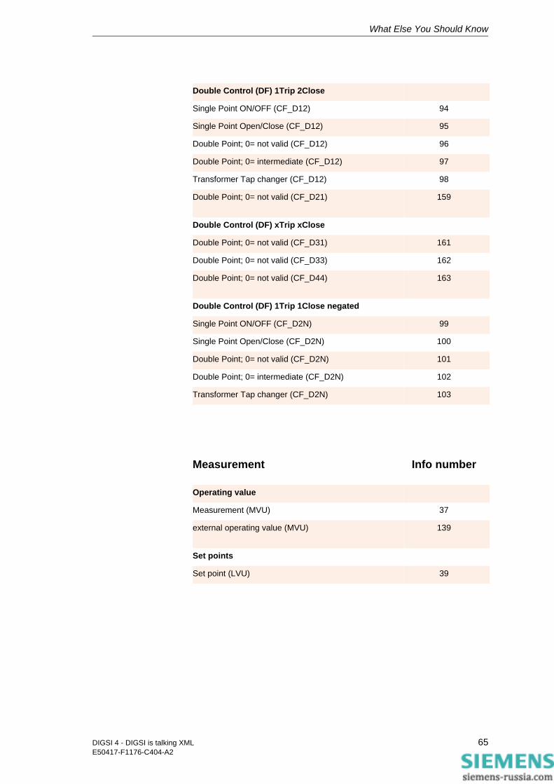
What Else You Should Know
Double Control (DF) 1Trip 2Close
Single Point ON/OFF (CF_D12) 94
Single Point Open/Close (CF_D12) 95
Double Point; 0= not valid (CF_D12) 96
Double Point; 0= intermediate (CF_D12) 97
Transformer Tap changer (CF_D12) 98
Double Point; 0= not valid (CF_D21) 159
Double Control (DF) xTrip xClose
Double Point; 0= not valid (CF_D31) 161
Double Point; 0= not valid (CF_D33) 162
Double Point; 0= not valid (CF_D44) 163
Double Control (DF) 1Trip 1Close negated
Single Point ON/OFF (CF_D2N) 99
Single Point Open/Close (CF_D2N) 100
Double Point; 0= not valid (CF_D2N) 101
Double Point; 0= intermediate (CF_D2N) 102
Transformer Tap changer (CF_D2N) 103
Measurement Info number
Operating value
Measurement (MVU) 37
external operating value (MVU) 139
Set points
Set point (LVU) 39
65DIGSI 4 - DIGSI is talking XMLE50417-F1176-C404-A2

What Else You Should Know
PowerMeter Info number
PowerMeter
PowerMeter (MVMV) 44
Pulse
Pulse (PMV) 42
66 DIGSI 4 - DIGSI is talking XMLE50417-F1176-C404-A2

Index
AAdd-in 44
Assign parameters 55Cell identifier 48Comparison function 54Direct address 48Export data 53Generate setting sheet 46Identifier 47, 48, 50, 53, 56Import data 47Install 44Overview 45Prepare setting sheet for export 55Reference device 47Reference file 55Restrict area for export 53Settings 45Show source and destination area 50Standard directory 45Validity check 54
Adopt settings of analog devices 56ASCII 5, 13Assignment of XML Code and DIGSI 4 19Attribute 9, 20
CCAPE 59Cell identifier 48, 49CFC 13Changing properties 33Code
Importing a segment 30Mini script 29, 33Reducing 27
Comment 21Compare
Device data 15, 37with reference device 54
Complete 36Contents 9Control
With feedback 64Without feedback 62
Converter 60
Copying function settings 31CSV 5, 13
DDAdr 21, 28Data consistency 54Data image 11dBase (DBF) 12Decimal parameter 21Delete 35
Information and groups 35No 35Yes 36
DeleteGroup 36Destination 25, 33Device
Description file 13Family 32Validation 37
Device dataCompare 15Transfer 16
DeviceData 22DeviceLanguage 38DEX 11
67DIGSI 4 - DIGSI is talking XML E50417-F1176-C404-A2
DIGSI XMLComment 21DAdr 21Delete 35Destination 25DeviceData 22DeviceLanguage 38DIGSILanguage 38FunctionGroup 20, 23General 22Group 24, 35Information 26, 35Language 39Name 21, 24Option 24, 35Parameters 23Properties 25Routing 22SettingGroup 24SettingPage 20, 23Settings 22Source 25Structure 22TextRef 24Type 21, 26Value 21
DIGSI XML Interface 44DIGSILanguage 38DIgSILENT 59Direct address 21, 28, 48, 54Download Area 44
EEditor, XML 18ELCAD 13Electrocon 59Element 9, 20
Attribute 9Contents 9Name 9
Energy RELEX 60Error scenarios 39, 41Excel 13, 53
Add-in 44Macro 56
ExportExcel data 53Formats 11Setting sheet 55Settings of analog protective gear 56
FFault situations 59
FunctionGroup 20, 23, 29
GGeneral 22Generate
Information and groups 34Setting sheet 46
Generic Coding 9Group 24, 35
Delete 35Generate 34
IICD 13Identifier 47, 48, 50, 53, 56IEC 60870-5-103 12Import
Formats 11Safety concept 37
ImportingIn DIGSI 4 15, 30In Excel 47
Indications 61Info number 61Info types 26Information 26, 35, 61
Changing routings and properties 33Delete 35Generate 35
Inserting information and groups 34Installing the Excel Add-in 44Internet Explorer 17IPS 59
KKeyboard shortcuts 45
LLanguage 39
Devices 39Set for Excel Add-in 45
Levels 18Line calculation 59Line data management 59, 60
MMacro
Adopt settings of analog devices 56Export settings 56
Master setting sheet 47Measurement 65MICS 13
68 DIGSI 4 - DIGSI is talking XMLE50417-F1176-C404-A2

NName 9, 21, 24, 26National language 22No 35Node 10, 18Notepad 18
OOMICRON 12, 59, 60Option 24, 35
Complete 36DeleteGroup 36Standard 35
PParameter set 20, 39, 41, 54Parameters 23
Assign 55Changing values 28
PDF 13Plausibility control 41PowerFactor 59PowerMeter 66Properties 25, 33Protection test 59, 60Protective data management 59
RReducing 27Reference 47Reference file 54, 55Report window 15RIO 12Root element 10, 22Routing 22, 33
Change 33
SSafety concept 37, 54
Device validation 37Plausibility control 41Syntax check 39
Save 39Search 54Secondary values 24Selection list 21Selection parameters 46Setting data 44Setting recommendations 59Setting sheet 43, 56
Create new 46Prepare for export 55
SettingGroup 24, 29SettingPage 20, 23, 29Settings 22
Adopt from analog protective gear 56for Excel Add-in 45
Show destination area 50Show source area 50SIGRADE 59SINCAL 59SIPROTEC Download Area 44Source 25, 33Spread-sheet 13Spreed-sheet calculation program 43Standard 35Standard directory 45Station instrumentation and control 12StationWare 60Structure
DIGSI XML 22XML general 9
Syntax check 39System interface 12, 13, 25
TTag 10TestBase 60Testuniverse 60Text selection parameter 21TextRef 24Tooltip 21Transferring data into device 16Type 21, 26, 33
UUnit, physical 21
VValidation 37Validity
Check 54Range 21, 41
Value 9, 20, 21, 54Value limits 46
WWell-formed 22
XXML
For protective data 11For system interface 12
69DIGSI 4 - DIGSI is talking XML E50417-F1176-C404-A2
XML CodeAttribute 9Element 9Exporting 14Importing 15Levels 18Node 10, 18Opening in the Editor 17Root element 10Tag 10Value 9
XRIO 12, 60
YYes 36
70 DIGSI 4 - DIGSI is talking XMLE50417-F1176-C404-A2