
Electricity and New Energy - Lab-Volt · Appendix C Introduction to the DIGSI 5 Software from...
55
Electricity and New Energy Directional Protection &RXUVHZDUH 6DPSOH 52174-)0
Transcript of Electricity and New Energy - Lab-Volt · Appendix C Introduction to the DIGSI 5 Software from...

Electricity and New Energy
Directional Protection
52174- 0

Order no.: 52174-10 First Edition Revision level: 11/2016
By the staff of Festo Didactic
© Festo Didactic Ltée/Ltd, Quebec, Canada 2016 Internet: www.festo-didactic.com e-mail: [email protected]
Printed in Canada All rights reserved ISBN 978-2-89747-560-4 (Printed version) ISBN 978-2-89747-562-8 (CD-ROM) Legal Deposit – Bibliothèque et Archives nationales du Québec, 2016 Legal Deposit – Library and Archives Canada, 2016
The purchaser shall receive a single right of use which is non-exclusive, non-time-limited and limited geographically to use at the purchaser's site/location as follows.
The purchaser shall be entitled to use the work to train his/her staff at the purchaser’s site/location and shall also be entitled to use parts of the copyright material as the basis for the production of his/her own training documentation for the training of his/her staff at the purchaser’s site/location with acknowledgement of source and to make copies for this purpose. In the case of schools/technical colleges, training centers, and universities, the right of use shall also include use by school and college students and trainees at the purchaser’s site/location for teaching purposes.
The right of use shall in all cases exclude the right to publish the copyright material or to make this available for use on intranet, Internet and LMS platforms and databases such as Moodle, which allow access by a wide variety of users, including those outside of the purchaser’s site/location.
Entitlement to other rights relating to reproductions, copies, adaptations, translations, microfilming and transfer to and storage and processing in electronic systems, no matter whether in whole or in part, shall require the prior consent of Festo Didactic.
Information in this document is subject to change without notice and does not represent a commitment on the part of Festo Didactic. The Festo materials described in this document are furnished under a license agreement or a nondisclosure agreement.
Festo Didactic recognizes product names as trademarks or registered trademarks of their respective holders.
All other trademarks are the property of their respective owners. Other trademarks and trade names may be used in this document to refer to either the entity claiming the marks and names or their products. Festo Didactic disclaims any proprietary interest in trademarks and trade names other than its own.

© Festo Didactic 52174-10 III
Safety and Common Symbols
The following safety and common symbols may be used in this manual and on the equipment:
Symbol Description
DANGER indicates a hazard with a high level of risk which, if not avoided, will result in death or serious injury.
WARNING indicates a hazard with a medium level of risk which, if not avoided, could result in death or serious injury.
CAUTION indicates a hazard with a low level of risk which, if not avoided, could result in minor or moderate injury.
CAUTION used without the Caution, risk of danger sign , indicates a hazard with a potentially hazardous situation which, if not avoided, may result in property damage.
Caution, risk of electric shock
Caution, hot surface
Caution, risk of danger. Consult the relevant user documentation.
Caution, lifting hazard
Caution, hand entanglement hazard
Notice, non-ionizing radiation
Direct current
Alternating current
Both direct and alternating current
Three-phase alternating current
Earth (ground) terminal
Safety and Common Symbols
IV © Festo Didactic 52174-10
Symbol Description
Protective conductor terminal
Frame or chassis terminal
Equipotentiality
On (supply)
Off (supply)
Equipment protected throughout by double insulation or reinforced insulation
In position of a bi-stable push control
Out position of a bi-stable push control

© Festo Didactic 52174-10 V
Table of Contents
Preface .................................................................................................................. IX
About This Manual ................................................................................................ XI
To the Instructor .................................................................................................. XIII
Introduction Directional Protection .................................................................. 1
DISCUSSION OF FUNDAMENTALS ....................................................... 1Overcurrent protection of radial feeders .................................. 1Protection of parallel power lines using overcurrent relays ..... 2Directional overcurrent protection ............................................ 4Directional comparison protection ........................................... 6Directional power protection .................................................... 7
Exercise 1 Directional Overcurrent Protection ............................................ 9
DISCUSSION ..................................................................................... 9Determining the direction in which an alternating current flows ......................................................................................... 9Operation of the directional overcurrent relay ....................... 11Typical value (45°) of the characteristic angle used in directional overcurrent relays ................................................ 13
PROCEDURE .................................................................................. 16Set up and connections ......................................................... 16Operation of a directional overcurrent relay .......................... 17
Forward direction zone ............................................................. 17Backward (reverse) direction zone ........................................... 23
Directional overcurrent protection of power lines connected in parallel .............................................................. 25
Operation of the overcurrent relays at locations C and D ......... 30Operation of the directional overcurrent relays at locations E and F ..................................................................... 32Analysis of the relay responses ............................................... 35
Ending the exercise ............................................................... 37
Exercise 2 Directional Comparison Protection .......................................... 39
DISCUSSION ................................................................................... 39Directional overcurrent protection with time coordination or time-current coordination ................................................... 39Directional comparison protection ......................................... 43Control logic of directional overcurrent relays used for directional comparison protection .......................................... 46

Table of Contents
VI © Festo Didactic 52174-10
PROCEDURE .................................................................................. 49Set up and connections ......................................................... 49Directional overcurrent protection of a three-segment ring bus .................................................................................. 50
Operation of the overcurrent relays at locations D and E ......... 56Operation of the directional overcurrent relays at locations F and G ..................................................................... 59Operation of the directional overcurrent relays at locations H and I ....................................................................... 62Analysis of the relay responses ................................................ 63
Directional comparison protection of a three-segment ring bus .................................................................................. 66
Operation of the directional overcurrent relay at location D ...... 68Operation of the directional overcurrent relay at location F ...... 71Analysis of the relay responses on the faulty line ..................... 74Operation of the directional overcurrent relays at locations H and I ....................................................................... 75Analysis of the relay responses on a healthy line ..................... 79Global analysis of the relay responses ..................................... 79
Ending the exercise ............................................................... 80
Exercise 3 Directional Power Protection .................................................... 83
DISCUSSION ................................................................................... 83Determining the value of power and the direction of power flow .............................................................................. 83
Active power ............................................................................. 84Reactive power ......................................................................... 85
Operation of the directional power relay ................................ 86Motoring protection ................................................................ 88Loss-of-excitation protection .................................................. 90
PROCEDURE .................................................................................. 93Set up and connections ......................................................... 93Directional power protection applied to a synchronous generator ............................................................................... 94
Motoring protection ................................................................... 96Loss-of-excitation protection................................................... 101
Ending the exercise ............................................................. 105
Appendix A Equipment Utilization Chart .................................................... 109
Appendix B Glossary of New Terms ........................................................... 111
Table of Contents
© Festo Didactic 52174-10 VII
Appendix C Introduction to the DIGSI 5 Software from Siemens ............ 113Setting the language used in DIGSI 5 ................................. 114Opening a project file ........................................................... 114Displaying the single-line diagram ....................................... 116Setting the frequency of operation of the protective relay ... 116Setting the language used in the front panel display of the protective relay .............................................................. 118Accessing the settings of a specific protection function of the relay ............................................................................... 118Accessing the parameters of a test sequence .................... 120Changing the ratio of current (or voltage) transformers ...... 121Enabling/disabling fault display ........................................... 123Loading a new configuration to the protective relay ............ 124Restarting the protective relay in the simulation (test) mode .................................................................................... 126Updating the test environment ............................................. 129Starting a test sequence ...................................................... 129Downloading a fault record from the protective relay .......... 131Displaying the signals stored in a fault record ..................... 132Restarting the protective relay in the process (normal operation) mode................................................................... 135
Appendix D Protective Relay LED Identification Labels ........................... 137
Appendix E Electrical Graphic Symbols (IEC and ANSI) .......................... 139
Index .................................................................................................................. 141
Bibliography ....................................................................................................... 143


© Festo Didactic 52174-10 IX
Preface
The production of energy using renewable natural resources such as wind, sunlight, rain, tides, geothermal heat, etc., has gained much importance in recent years as it is an effective means of reducing greenhouse gas (GHG) emissions. The need for innovative technologies to make the grid smarter has recently emerged as a major trend, as the increase in electrical power demand observed worldwide makes it harder for the actual grid in many countries to keep up with demand. Furthermore, electric vehicles (from bicycles to cars) are developed and marketed with more and more success in many countries all over the world.
To answer the increasingly diversified needs for training in the wide field of electrical energy, the Electric Power Technology Training Program was developed as a modular study program for technical institutes, colleges, and universities. The program is shown below as a flow chart, with each box in the flow chart representing a course.
The Electric Power Technology Training Program.

Preface
X © Festo Didactic 52174-10
The program starts with a variety of courses providing in-depth coverage of basic topics related to the field of electrical energy such as ac and dc power circuits, power transformers, rotating machines, ac power transmission lines, and power electronics. The program then builds on the knowledge gained by the student through these basic courses to provide training in more advanced subjects such as home energy production from renewable resources (wind and sunlight), large-scale electricity production from hydropower, large-scale electricity production from wind power (doubly-fed induction generator [DFIG], synchronous generator, and asynchronous generator technologies), smart-grid technologies (SVC, STATCOM, HVDC transmission, etc.), storage of electrical energy in batteries, and drive systems for small electric vehicles and cars.
We invite readers of this manual to send us their tips, feedback, and suggestions for improving the book.
Please send these to [email protected].
The authors and Festo Didactic look forward to your comments.

© Festo Didactic 52174-10 XI
About This Manual
Manual objectives
When you have completed this manual, you will be familiar with the operation and settings of the directional overcurrent relay (ANSI device no. 67). You will learn about directional overcurrent protection and directional comparison protection, which are two ways to protect power lines connected in parallel or forming a ring bus. You will understand how directional comparison protection uses a communication link between two directional overcurrent relays to allow fast clearing of faults. You will be familiar with the operation and settings of the directional power relay (ANSI device no. 32). You will learn how directional power protection can prevent damage to the prime mover of a synchronous generator when it stops driving the generator. You will also see how directional power protection can prevent damage to a synchronous generator resulting from sustained operation as an asynchronous generator following a loss of excitation.
Safety considerations
Safety symbols that may be used in this manual and on the equipment are listed in the Safety Symbols table at the beginning of the manual.
Safety procedures related to the tasks that you will be asked to perform are indicated in each exercise.
Make sure that you are wearing appropriate protective equipment when performing the tasks. You should never perform a task if you have any reason to think that a manipulation could be dangerous for you or your teammates.
Prerequisite
As a prerequisite to this course, you should have read the manuals titled DC Power Circuits, part number 86350, Single-Phase AC Power Circuits, part number 86358, Single-Phase Power Transformers, part number 86377, Three-Phase AC Power Circuits, part number 86360, Three-Phase Transformer Banks, part number 86379, and Overcurrent and Overload Protection Using Protective Relays, part number 52173.
Systems of units
Units are expressed using the International System of Units (SI) followed by units expressed in the U.S. customary system of units (between parentheses).
Voltage symbol
Voltages are represented using the letter “E”. In certain countries, the letter “U” is rather used to represent voltages.


© Festo Didactic 52174-10 XIII
To the Instructor
You will find in this Instructor Guide all the elements included in the Student Manual together with the answers to all questions, results of measurements, graphs, explanations, suggestions, and, in some cases, instructions to help you guide the students through their learning process. All the information that applies to you is placed between markers and appears in red.
Accuracy of measurements
The numerical results of the hands-on exercises may differ from one student to another. For this reason, the results and answers given in this manual should be considered as a guide. Students who correctly performed the exercises should expect to demonstrate the principles involved and make observations and measurements similar to those given as answers.
Detailed procedure in Exercise 1
It is recommended to perform the exercises in the order proposed in this manual, as Exercise 1 features more detailed explanations than the rest of the exercises.


Sample
Extracted from
Instructor Guide


© Festo Didactic 52174-10 1
When you have completed this manual, you will be familiar with the operation and settings of the directional overcurrent relay (ANSI device no. 67). You will learn about directional overcurrent protection and directional comparison protection, which are two ways to protect power lines connected in parallel or forming a ring bus. You will understand how directional comparison protection uses a communication link between two directional overcurrent relays to allow fast clearing of faults. You will be familiar with the operation and settings of the directional power relay (ANSI device no. 32). You will learn how directional power protection can prevent damage to the prime mover of a synchronous generator when it stops driving the generator. You will also see how directional power protection can prevent damage to a synchronous generator resulting from sustained operation as an asynchronous generator following a loss of excitation.
The Discussion of Fundamentals covers the following points:
Overcurrent protection of radial feeders Protection of parallel power lines using overcurrent relays Directional overcurrent protection Directional comparison protection Directional power protection
Overcurrent protection of radial feeders
In a distribution network or an industrial application, a radial feeder is a line used to convey electric power, which has a radial structure and is powered at one end only. The power source side of the radial feeder generally consists of a single power transformer or two or more power transformers connected in parallel. Along the radial feeder, substation busses are present to which loads are connected to provide power, for example, to a small town or village. The power lines between the substations are called feeder segments. The infeed of a feeder segment refers to its end on the source side.
It is common to use overcurrent protection to protect radial feeders against faults that give rise to the flow of excessive currents. Protection of radial feeders is commonly achieved by installing a circuit breaker and an overcurrent relay with its associated current transformers at the infeed of each feeder segment. Figure 1 shows a radial feeder protected this way. For the sake of simplicity, only the circuit breaker at the infeed of each feeder segment is shown in this figure, and the power transformers and fuses feeding the loads at substation busses A, B, C, and D have been omitted.
Directional Protection
Introduction
MANUAL OBJECTIVE
DISCUSSION OUTLINE
DISCUSSION OF FUNDAMENTALS

Introduction – Directional Protection Discussion of Fundamentals
2 © Festo Didactic 52174-10
Figure 1. Single-line diagram of a radial feeder with overcurrent protection.
Using circuit breakers and overcurrent relays at different locations along a radial feeder is essential to achieve discriminative protection. This type of protection disconnects the minimum amount of circuit to isolate the fault and thereby limits the number of loads that lose power. To obtain proper discrimination when protecting a radial feeder with several circuit breakers and overcurrent relays, the operation of the overcurrent relays must be properly coordinated. This is referred to as relay coordination or relay grading. Several methods exist to achieve relay coordination. In short, one must determine the characteristics of the protected radial feeder and adjust the time and/or current settings of the overcurrent relays in such a manner that the relay closest to the fault trips first.
a The coordination of overcurrent relays is presented in Exercise 3 of the manual Overcurrent and Overload Protection Using Protective Relays, p/n 52173.
Protection of parallel power lines using overcurrent relays
Equipment redundancy is common in electric power systems, since one piece of equipment can fail without interrupting the supply of power. The use of multiple generators, lines, and/or transformers thus improves the availability of power. Similarly, equipment redundancy facilitates maintenance, since the piece of equipment requiring maintenance can be put out of service temporarily without interrupting the supply of power. Also, using multiple lines in parallel (see Figure 2) is common, because it allows more power to be conveyed to a given location. Equipment redundancy and the use of parallel power lines help in making the power grid smart.
Feeder segment
Transformer Substation
bus
Loads
Fuse
A
B C D Infeed
Load
Introduction – Directional Protection Discussion of Fundamentals
© Festo Didactic 52174-10 3
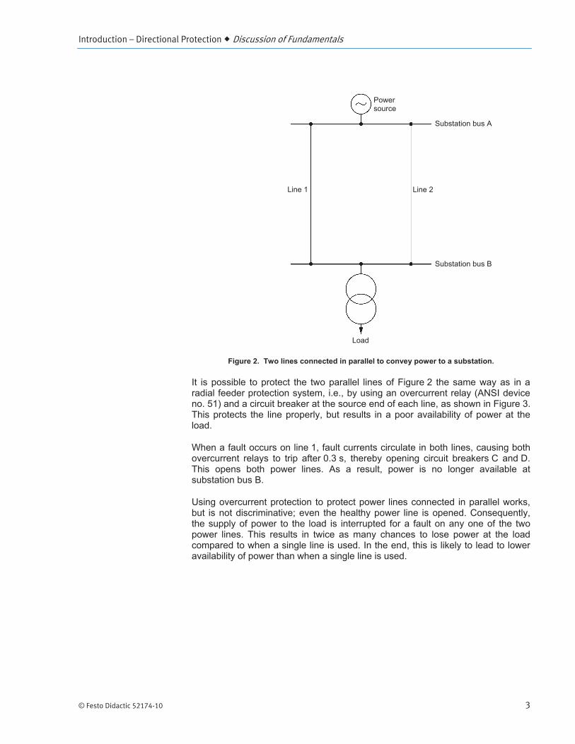
Figure 2. Two lines connected in parallel to convey power to a substation.
It is possible to protect the two parallel lines of Figure 2 the same way as in a radial feeder protection system, i.e., by using an overcurrent relay (ANSI device no. 51) and a circuit breaker at the source end of each line, as shown in Figure 3. This protects the line properly, but results in a poor availability of power at the load.
When a fault occurs on line 1, fault currents circulate in both lines, causing both overcurrent relays to trip after 0.3 s, thereby opening circuit breakers C and D. This opens both power lines. As a result, power is no longer available at substation bus B.
Using overcurrent protection to protect power lines connected in parallel works, but is not discriminative; even the healthy power line is opened. Consequently, the supply of power to the load is interrupted for a fault on any one of the two power lines. This results in twice as many chances to lose power at the load compared to when a single line is used. In the end, this is likely to lead to lower availability of power than when a single line is used.
Power source
Substation bus A
Substation bus B
Load
Line 1 Line 2

Introduction – Directional Protection Discussion of Fundamentals
4 © Festo Didactic 52174-10
Figure 3. Protection of two parallel lines using overcurrent relays.
Directional overcurrent protection
Directional overcurrent relays are required to achieve discriminative protection of the two power lines in Figure 3. A directional overcurrent relay is referred to as a device no. 67 as per ANSI standard C37.2. It is defined as “a relay that functions on a desired value of ac overcurrent flowing in a predetermined direction”. In other words, it is an overcurrent relay that trips only when the fault current flows in a given direction. Exercise 1 of this manual covers the operation of directional overcurrent relays in detail.
a In the context of alternating current (ac) power systems, the polarity of current cannot be used to establish the direction of current flow. Instead, the phase shift between current and voltage is used, as explained in the discussion of Exercise 1.
Proper fault discrimination is achieved when one uses directional overcurrent relays to protect parallel power lines, as shown in Figure 4.
a A directional overcurrent relay measures the circuit voltage via a voltage transformer. The voltage transformers have been omitted in Figure 4 for the sake of clarity.
ANSI is the common abbre-viation used to refer to the American National Stand-ards Institute.
Power source
Substation bus A
Substation bus B
Load
Line 1 Line 2
C D
Fault currents
Fault
0.3 s 51DT
0.3 s 51 DT
IF1 IF2

Introduction – Directional Protection Discussion of Fundamentals
© Festo Didactic 52174-10 5
Figure 4. Directional overcurrent protection of two power lines connected in parallel.
When a fault occurs on line 1, fault current IF1 flows through line 1. Fault current IF2 also flows through line 1, but in the opposite direction. The directional overcurrent relay at location E trips and opens the corresponding circuit breaker 0.1 s after the fault occurred, because fault current IF2 flows in the same direction as the direction set in the relay (indicated in Figure 4 by the arrow beside the directional overcurrent relay symbol). On the other hand, the directional overcurrent relay at location F does not trip, because fault current IF2 flows in the direction opposite to the direction set in the relay. Consequently, fault current IF2 is interrupted when the circuit breaker at location E opens, i.e., 0.1 s after the fault occurred.
Fault current IF1 still flows through line 1 after the circuit breaker at location E opened. However, the overcurrent relay at location C trips and opens the corresponding circuit breaker 0.4 s after the fault occurred, thereby interrupting fault current IF1.
As a result, the protection isolated the fault while achieving proper discrimination: the faulty line (line 1) has been disconnected and the healthy line (line 2) has been left in service. Consequently, power is still available at substation bus B, thereby maintaining the availability of power at the load.
Power source
Substation bus A
Substation bus B
Load
Line 1 Line 2
C D
Fault currents
Fault
0.4 s
51DT
0.4 s
E
0.1 s
67 F
0.1 s
67
IF1 IF251 DT

Introduction – Directional Protection Discussion of Fundamentals
6 © Festo Didactic 52174-10
A time setting of 0.4 s is used on the overcurrent relay at location D to allow the directional overcurrent relay at location E to trip first when a fault occurs on line 1. This ensures that line 2 is not disconnected when a fault occurs on line 1, thereby achieving proper fault discrimination. Similarly, the same time setting of 0.4 s is used for the overcurrent relay at location C to allow the directional overcurrent relay at location F to trip first when a fault occurs on line 2. This ensures that line 1 is not disconnected when a fault occurs on line 2.
When overcurrent protection is used to protect parallel power lines, both an overcurrent relay and a directional overcurrent relay are required on each line to achieve proper fault discrimination. This kind of protection is commonly referred to as directional overcurrent protection.
Exercise 1 of this manual deals with the operation of the directional overcurrent relay and the directional overcurrent protection applied to power lines connected in parallel.
Figure 5. Parallel power lines.
Directional comparison protection
Directional overcurrent protection, when applied to parallel power lines, remains simple and allows faults to be cleared in relatively short times, while achieving proper discrimination. However, when the topology of the power system becomes more complex, relay coordination involves more than just two relays. Unfortunately, the time required to clear faults increases with the number of relays to be coordinated. Depending on the application, longer fault clearing times may or may not be acceptable for various reasons. When the fault clearing times achieved using directional overcurrent protection and relay coordination based on either time alone or time and current are judged unacceptable, directional comparison protection can be used to minimize fault clearing times.
In this example of direction-al overcurrent protection of two power lines in parallel, fault discrimination is based on time coordination achieved using definite time overcurrent relays. Inverse definite minimum time (IDMT) overcurrent relays can also be used to achieve time-current coor-dination.

Introduction – Directional Protection Discussion of Fundamentals
© Festo Didactic 52174-10 7
Directional comparison protection uses a pair of directional overcurrent relays to protect each segment of a power line, the relays being located at the two ends of the protected line segment. Each directional overcurrent relay in a pair can communicate with the relay at the other end of the protected line segment via a communication link (optical fiber, microwave communication system, etc.). This key feature allows the implementation of fast relay tripping schemes providing short fault clearing times.
Exercise 2 of this manual explains how directional comparison protection works.
Directional power protection
A protective relay that measures the current and voltage at a given point of a circuit, like a directional overcurrent relay, is also able to determine the value of power at the point of measurement as well as the direction of power flow. Such a protective relay is referred to as a directional power relay (ANSI device no. 32). Directional power relays are used to implement directional power protection.
For instance, directional power protection can be implemented to prevent damage to a prime mover (e.g., a steam turbine) when it stops driving a synchronous generator connected to the power network. In short, this is achieved by measuring active power at the generator stator and generating an alarm when the direction of active power flow reverses, which means that the generator begins to draw active power from the network because it begins to operate as a synchronous motor. After a certain time delay, a trip command is generated to disconnect the synchronous generator from the power network, thereby stopping generator motoring and preventing damage to the prime mover. This type of directional power protection is commonly referred to as motoring protection or reverse power protection.
Directional power protection can also be used to protect a synchronous generator against a loss of excitation (LOE). Losing excitation causes a synchronous generator to operate as an asynchronous generator, a condition of operation that can eventually result in damage to the synchronous generator. In short, this protection is achieved by measuring the reactive power at the generator stator and generating a trip command, either immediately or shortly after the LOE event, to shutdown the synchronous generator before damage due to sustained operation as an asynchronous generator occurs. This type of directional power protection is commonly referred to as loss-of-excitation protection or loss-of-field protection.
Exercise 3 of this manual deals with directional power protection.


© Festo Didactic 52174-10 9
In this exercise, you will learn how to determine the direction in which an alternating current flows. You will become familiar with the operation of a directional overcurrent relay, including its main settings. You will analyze the phasors of fault currents on a given phase to understand why the characteristic angle in a directional overcurrent relay is commonly set to 45°. You will verify the angular limits of the forward and backward direction zones of a directional overcurrent relay. You will learn how directional overcurrent protection achieves discriminative protection of two power lines connected in parallel.
The Discussion of this exercise covers the following points:
Determining the direction in which an alternating current flows Operation of the directional overcurrent relay Typical value (45°) of the characteristic angle used in directional
overcurrent relays
Determining the direction in which an alternating current flows
Current in any conductor of an electric circuit can flow from left to right or from right to left. This is commonly referred to as the direction of current flow. In dc power circuits, the polarity of the current indicates the direction of current flow. In ac power circuits, however, the polarity of the current alternates constantly. Consequently, polarity cannot be used to determine the direction of current flow.
In an ac power circuit, one determines the direction of current flow from the phase shift between the voltage E and the current I at any given point of the circuit (refer to Figure 6a).
When the current flows from left to right in the circuit, the absolute value of the phase shift between the voltage and current is 90° or less (Figure 6b), the exact value of the phase shift being dependent on the value of the circuit impedance Z. This direction is generally considered as the forward direction. On the other hand, when the current flows from right to left in the circuit, the absolute value of the phase shift between the voltage and current is 90° or more (Figure 6c), the exact value of the phase shift being dependent on the value of the circuit impedance Z. This direction is generally considered as the reverse direction.
Directional Overcurrent Protection
Exercise 1
EXERCISE OBJECTIVE
DISCUSSION OUTLINE
DISCUSSION
The term reverse direction is commonly used to refer to the backward direction. Both terms are used in this manual.

Exercise 1 – Directional Overcurrent Protection Discussion
10 © Festo Didactic 52174-10
Figure 6. Determining the direction of current flow in an ac power circuit.
a Phase angle values can be expressed over a range of 0° to 360° or over a range of -180° to 180°. In the phasor diagrams provided in this manual, phase angle values are expressed over a range of 0° to 360°. For practicality, however, phase angle values between -180° and 0° are also provided (shown in parentheses).
In most power networks, the impedance is of resistive-inductive nature. In this case, the expected range of phase angle values of the current is reduced to 90° for each direction of current flow, as shown in Figure 7.
Forward
Reverse
Z Z
I
E
(a) Circuit diagram
(b) Current flows in forward direction
(c) Current flows in reverse direction
I
E
I
0°
90°
180°(-180°)
270° (-90°)
0°
90°
180°(-180°)
270° (-90°)
E

Exercise 1 – Directional Overcurrent Protection Discussion
© Festo Didactic 52174-10 11
Figure 7. Determining the direction of current flow in an ac power circuit (resistive-inductive impedance only).
Operation of the directional overcurrent relay
The directional overcurrent relay is the key component to achieve directional overcurrent protection, as discussed in the Introduction of this manual. The operation of the directional overcurrent relay (ANSI device no. 67) along with its main parameters are explained below.
A directional overcurrent relay (ANSI device no. 67) mainly consists of an overcurrent relay plus a directional element that determines the direction of current flow.
A directional overcurrent relay measures current and voltage at a given point of the circuit, as shown in Figure 8. From these measurements, the directional element is able to determine the direction of current flow.
Forward
Reverse
Z Z
I
E
(a) Circuit diagram
(b) Current flows in forward direction
(c) Current flows in reverse direction
I
E
I
0°
90°
180°(-180°)
270° (-90°)
0°
90°
180°(-180°)
270° (-90°)
E
Exercise 1 – Directional Overcurrent Protection Discussion
12 © Festo Didactic 52174-10
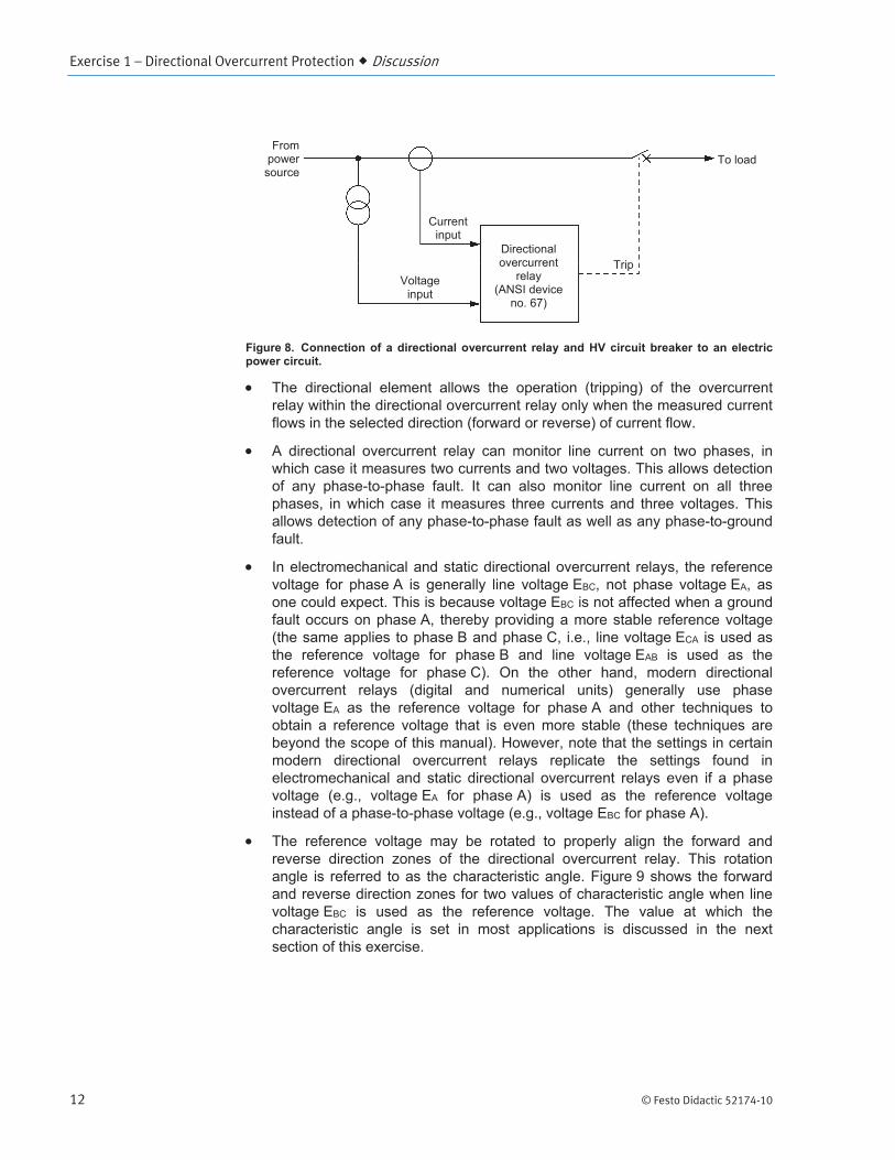
Figure 8. Connection of a directional overcurrent relay and HV circuit breaker to an electric power circuit.
The directional element allows the operation (tripping) of the overcurrent relay within the directional overcurrent relay only when the measured current flows in the selected direction (forward or reverse) of current flow.
A directional overcurrent relay can monitor line current on two phases, in which case it measures two currents and two voltages. This allows detection of any phase-to-phase fault. It can also monitor line current on all three phases, in which case it measures three currents and three voltages. This allows detection of any phase-to-phase fault as well as any phase-to-ground fault.
In electromechanical and static directional overcurrent relays, the reference voltage for phase A is generally line voltage EBC, not phase voltage EA, as one could expect. This is because voltage EBC is not affected when a ground fault occurs on phase A, thereby providing a more stable reference voltage (the same applies to phase B and phase C, i.e., line voltage ECA is used as the reference voltage for phase B and line voltage EAB is used as the reference voltage for phase C). On the other hand, modern directional overcurrent relays (digital and numerical units) generally use phase voltage EA as the reference voltage for phase A and other techniques to obtain a reference voltage that is even more stable (these techniques are beyond the scope of this manual). However, note that the settings in certain modern directional overcurrent relays replicate the settings found in electromechanical and static directional overcurrent relays even if a phase voltage (e.g., voltage EA for phase A) is used as the reference voltage instead of a phase-to-phase voltage (e.g., voltage EBC for phase A).
The reference voltage may be rotated to properly align the forward and reverse direction zones of the directional overcurrent relay. This rotation angle is referred to as the characteristic angle. Figure 9 shows the forward and reverse direction zones for two values of characteristic angle when line voltage EBC is used as the reference voltage. The value at which the characteristic angle is set in most applications is discussed in the next section of this exercise.
Frompower
source
Current input
Voltage input
Directional overcurrent
relay (ANSI device
no. 67)
Trip
To load

Exercise 1 – Directional Overcurrent Protection Discussion
© Festo Didactic 52174-10 13
Figure 9. Selecting a characteristic angle to properly align the forward and reverse direction zones of the directional overcurrent relay.
The main settings of a directional overcurrent relay are:
- Direction of current flow (forward or reverse)
- Current threshold, also referred to as the current setting. This is the minimum current for which the directional overcurrent relay may trip.
- Time delay, also referred to as the time setting or the operate delay. This is the operating time of the relay when a definite-time overcurrent relay (ANSI device no. 51DT) is used in the directional overcurrent relay. When an inverse definite minimum time overcurrent relay (ANSI device no. 51I) is used, the operating time is calculated according to the chosen time-current characteristic.
- Characteristic angle. Angle by which the reference voltage is rotated to allow proper operation of the directional overcurrent relay. This angle is generally set to 45°. This is explained in the following section.
Typical value (45°) of the characteristic angle used in directional overcurrent relays
The range of phase angle values of current expected for faults on phase A includes the ranges of phase angle values for a phase-to-ground fault, a phase-to-phase fault between phase A and phase B, and a phase-to-phase fault
Forward direction zone
Reverse direction zone
(a) No rotation of reference voltage
(characteristic angle = 0°)
EA 0°
90°
180°(-180°)
270° (-90°)
EBC, ERef
(b) Rotated reference voltage (characteristic angle = 90°)
EA 0°
90°
180°(-180°)
270° (-90°)
EBC
ERef
Characteristic angle

Exercise 1 – Directional Overcurrent Protection Discussion
14 © Festo Didactic 52174-10
between phase A and phase C. These three cases are treated separately below to ease understanding. The circuit impedance considered is of resistive-inductive nature, as this is representative of actual circuit impedances.
When a phase-to-ground fault occurs on phase A, the range of phase angle values of current IA that is expected is illustrated in Figure 10.
Figure 10. Range of phase angle values of current IA expected for a phase-to-ground fault on phase A.
The ranges of phase angle values of current IA expected for phase-to-phase faults between phase A and phase B and between phase A and phase C are shown in Figure 11.
Figure 11. Ranges of phase angle values of current IA expected for phase-to-phase faults between phase A and phase B (left) and between phase A and phase C (right).
EA
EC
EB
IA
EAB
0°
90°
180°(-180°)
270° (-90°)
Purely-inductive impedance
EA
EC
EB IA
0°
90°
180°(-180°)
270° (-90°)
Purely-inductive impedance
Purely-resistive impedance
EAC
EA
EC
EB
IA
0°
90°
180°(-180°)
270° (-90°)
Purely-inductiveimpedance
Purely-resistive impedance
Purely-resistive impedance

Exercise 1 – Directional Overcurrent Protection Discussion
© Festo Didactic 52174-10 15
The superposition of the ranges of phase angle values of current IA involved in Figure 10 and Figure 11 is presented in Figure 12. The total range covers 150°. Similarly, the total range of phase angle values of the current is also 150° for faults on phase B or phase C.
Figure 12. Range of phase angle values of current IA expected for faults on phase A.
Setting the characteristic angle to 45° properly aligns the forward and reverse direction zones of the directional overcurrent relay with the vectors of fault current expected for phase A, as illustrated in Figure 13. Notice that the forward direction zone encloses every expected vector of fault current for phase A with a safety margin of 15° on each side of the expected range of phase angle values of current. This ensures optimal operation of the directional overcurrent relay.
Figure 13. Setting the characteristic angle to 45° properly aligns the forward and reverse direction zones of the directional overcurrent relay with the range of phase angle values expected for the fault currents.
Forward direction zone
Reverse direction zone
EBC
ERef
Characteristic angle = 45°
EA
EC
EB
IA
0°
90°
180°(-180°)
270° (-90°)
0°
90°
180°(-180°)
270° (-90°)
15°
15°

Exercise 1 – Directional Overcurrent Protection Procedure Outline
16 © Festo Didactic 52174-10
The Procedure is divided into the following sections:
Set up and connections Operation of a directional overcurrent relay
Forward direction zone. Backward (reverse) direction zone. Directional overcurrent protection of power lines connected in parallel
Operation of the overcurrent relays at locations C and D. Operation of the directional overcurrent relays at locations E and F. Analysis of the relay responses.
Ending the exercise
a Appendix C of this manual provides information on how to use software DIGSI
® 5 to perform various tasks related to SIPROTEC ® 5 protective relays.
You should read this appendix before performing the exercise procedure.
Set up and connections
In this section, you will set up a protective relay so that it can be programmed and tested using a host computer.
1. Refer to the Equipment Utilization Chart in Appendix A to obtain the list of equipment required to perform this exercise.
Install the Numerical Directional Overcurrent Relay (Model 3812) and the host computer on your work surface.
a This exercise can also be performed using the Numerical Distance Relay (Model 3813). The term protective relay is used throughout the remainder of this exercise procedure to refer to the protective relay used to perform the exercise.
Insert the LED identification label for Exercise 1 into the front panel of the protective relay. The identification labels can be found in Appendix D.
2. Connect the protective relay and the host computer to an ac power wall outlet.
Turn the protective relay on. Wait for the protective relay to complete its initialization routine (this generally takes about 45 s).
3. Connect the USB port of the protective relay to a USB port of the host computer.
4. Turn the host computer on, then start the DIGSI 5 software.
PROCEDURE OUTLINE
PROCEDURE

Exercise 1 – Directional Overcurrent Protection Procedure
© Festo Didactic 52174-10 17
Operation of a directional overcurrent relay
In this section, you will establish the phase angle limits of the forward and backward direction zones of a directional overcurrent relay (ANSI device no. 67).
Forward direction zone
5. In DIGSI 5, open project file Directional Overcurrent Protection.dp5v6 created for the protective relay that you are using to perform the exercise. A project file contains the complete configuration of the protective relay for a particular application. By default, the project files required to perform the exercises in this manual should be located in the following folder: C:\ProgramData\Festo Didactic\Manual 52174, Directional Protection\...
a Refer to Appendix C to learn how to perform various tasks in software DIGSI 5.
6. In DIGSI 5, display the single-line diagram showing the connection of the protective relay to the electric power circuit. Observe that in this project, the current inputs of the protective relay are connected to the electric power circuit (a feeder in an electric power substation) via current transformers having a 200 A/1 A ratio. Also, the voltage inputs of the protective relay are connected to the electric power circuit via Y-connected (star-connected) voltage transformers having a 100 kV/100 V ratio. For example, when the bus voltage is 120 kV, the voltage at the primary windings of the voltage transformers is 69.3 kV and the voltage at the secondary windings is 69.3 V.
a A ratio of 100 kV to 100 V eases calculations of voltage values at the secondary windings of the voltage transformers. This ratio is not commonly available in practice and is employed here strictly for educational purposes.
7. In DIGSI 5, set the frequency of operation (Rated frequency parameter) of the protective relay to the frequency of your local ac power network.
Set the language used in the front panel display of the protective relay to the language used in DIGSI 5.
8. In DIGSI 5, access the settings of the directional overcurrent protection function of the protective relay. In the Project tree area of DIGSI 5, the directional overcurrent protection function is called 67 Dir.OC-3ph-A1 and is located in protection function group VI 3ph 1.
Make the following observations about the directional overcurrent protection function:
The characteristic angle (parameter Rotation angle of ref. volt. in the General section) is set to 45°.
The other parameters of the protection function are defined in time-current characteristic Definite-T1. Note that the Mode parameter is set to on, meaning that the protection function is activated.
The direction of current flow (parameter Directional mode) is set to forward.

Exercise 1 – Directional Overcurrent Protection Procedure
18 © Festo Didactic 52174-10
The protective relay has a definite-time characteristic, because the time delay (parameter Operate delay) is set to 0.1 s.
The current threshold of the protective relay (parameter Threshold) is set to 400 A.
Time-current characteristic Definite-T1 is displayed in the right region of the working area of DIGSI 5.
a The x-axis in the diagram showing the time-current characteristic of the protection function is graduated with values of current at the secondary windings of the current transformers. These values of current must be multiplied by the ratio of the current transformers (200 A/1 A in the currently-open project) to obtain values of current at the primary windings of the current transformers (i.e., values of current in the electric power circuit).
With voltage EBC as the reference voltage and the value of the characteristic angle presented above, the forward and backward direction zones of the directional overcurrent relay are the same as those shown in Figure 13.
9. In DIGSI 5, access the settings of the overcurrent protection function of the protective relay. In the Project tree area of DIGSI 5, the directional overcurrent protection function is called 50/51 OC-3ph-B1 or 50/51 OC-3ph-A and is located in protection function group VI 3ph 1.
This function is inactive (Mode parameter is set to off) for now, but will be used later in this exercise procedure.
10. In DIGSI 5, access the parameters of test sequence Directional OC Relay Operation. This test sequence is part of the project file currently open in DIGSI 5 and can be used to test the directional overcurrent protection function of the protective relay using its internal relay test system.
a In all test sequences, the magnitudes are expressed as secondary values, i.e., the values at the secondary windings of the current and voltage transformers.
Make the following observations about test sequence Directional OC Relay Operation.
The test sequence consists of two steps.
The first step (step 1) has a duration of 5.0 s.
During the first step, the internal relay test system emulates balanced currents of 1.00 A at the current inputs of the relay. This is equivalent to balanced currents of 200 A in the electric power circuit, because 200 A/1 A current transformers are used in this project.
During the first step, the internal relay test system emulates balanced voltages of 69.3 V at the voltage inputs of the relay. This is equivalent to balanced line-to-neutral voltages of 69.3 kV in the electric power circuit, because 100 kV/100 V voltage transformers (Y-connected) are used in this project.
The second step (step 2) has a duration of 72.0 s.

Exercise 1 – Directional Overcurrent Protection Procedure
© Festo Didactic 52174-10 19
During the second step, the internal relay test system emulates a current of 2.50 A at the phase-A current input of the relay. This is equivalent to a current of 500 A in the electric power circuit. Also, the phase angle of this current increases linearly from -180° to 180°, as shown in Figure 14, thereby covering the entire range of possible phase angle values.
Figure 14. Phase angle of the current at phase A during step 2 of test sequence Directional OC Relay Operation.
During the second step, the currents emulated for phase B and phase C, as well as all of the emulated voltages, are the same as those emulated during step 1.
By default, the frequency of the currents and voltages emulated by the internal relay test system during both steps of the sequence is set to 50 Hz.
Set the frequency of the currents and voltages emulated during both steps of test sequence Directional OC Relay Operation to the frequency of your local ac power network.
11. Load the configuration (i.e., the content of the project file currently open) to the protective relay using DIGSI 5. This step generally takes some time.
12. In DIGSI 5, restart the protective relay in the simulation mode to allow the directional overcurrent protection function of the protective relay (i.e., protection function 67 Dir.OC-3ph-A1 in protection function group VI 3ph 1) to be tested using the internal relay test system. Once the restart process is completed, the test environment should be displayed in DIGSI 5. Also, the front panel display of the protective relay should indicate that the unit is operating in the simulation mode (the words Simulation mode should appear briefly on the display at regular intervals).
a The Error LED on the front panel of the protective relay lights up when the unit is in simulation mode. This is normal. Do not be concerned about this error indication.
Time (seconds)
Pha
se a
ngle

Exercise 1 – Directional Overcurrent Protection Procedure
20 © Festo Didactic 52174-10
a During this procedure, if you notice that DIGSI 5 lags relay operation, press the Clear list button at the top of the test environment. This should restore normal operation of DIGSI 5.
13. In DIGSI 5, start test sequence Directional OC Relay Operation, then observe the front panel of the protective relay to see how it responds to the currents and voltages emulated by its internal relay test system.
a The relay display refreshes every 1 or 2 seconds.
Note that the protective relay displays the magnitude and phase of the measured currents and voltages. For 5 seconds, the values of the balanced currents and voltages are displayed, then the magnitude of the current of phase A increases to 500 A and its phase angle decreases to -180°. The phase angle then slowly increases up to a value of 180°. Eventually, LED indicators 1, 9, and 16 light up.
Table 1 provides the functions of the LED indicators of the protective relay (i.e., the column of 16 LEDs located on the left-hand side of the front panel). These functions are included in the configuration loaded to the protective relay.
Table 1. Functions of the LED indicators on the front panel of the protective relay.
LED indicator number
LED color Function
1 Red Pickup indication for phase A. The LED lights up when either the overcurrent protection function or the directional overcurrent protection function picks up.
2 Red Same as LED indicator 1 for phase B.
3 Red Same as LED indicator 1 for phase C.
7 Red Overcurrent protection function tripped indication. The LED lights up when the overcurrent protection function trips the protective relay.
9 Red Directional overcurrent protection function tripped indication. The LED lights up when the directional overcurrent protection function trips the protective relay.
16 Red Relay tripped indication. The LED lights up when the protective relay trips.
a The LED indicators are numbered 1 to 16 from the top to the bottom of the column, respectively.
Exercise 1 – Directional Overcurrent Protection Procedure
© Festo Didactic 52174-10 21
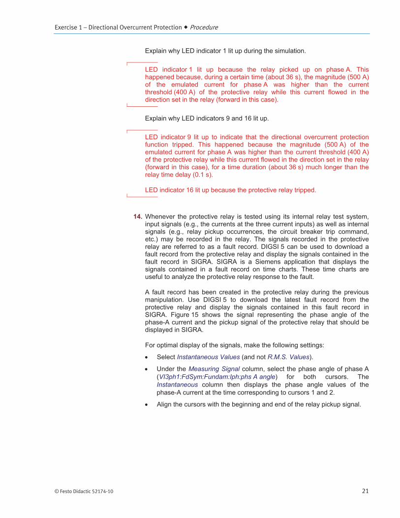
Explain why LED indicator 1 lit up during the simulation.
LED indicator 1 lit up because the relay picked up on phase A. This happened because, during a certain time (about 36 s), the magnitude (500 A) of the emulated current for phase A was higher than the current threshold (400 A) of the protective relay while this current flowed in the direction set in the relay (forward in this case).
Explain why LED indicators 9 and 16 lit up.
LED indicator 9 lit up to indicate that the directional overcurrent protection function tripped. This happened because the magnitude (500 A) of the emulated current for phase A was higher than the current threshold (400 A) of the protective relay while this current flowed in the direction set in the relay (forward in this case), for a time duration (about 36 s) much longer than the relay time delay (0.1 s).
LED indicator 16 lit up because the protective relay tripped.
14. Whenever the protective relay is tested using its internal relay test system, input signals (e.g., the currents at the three current inputs) as well as internal signals (e.g., relay pickup occurrences, the circuit breaker trip command, etc.) may be recorded in the relay. The signals recorded in the protective relay are referred to as a fault record. DIGSI 5 can be used to download a fault record from the protective relay and display the signals contained in the fault record in SIGRA. SIGRA is a Siemens application that displays the signals contained in a fault record on time charts. These time charts are useful to analyze the protective relay response to the fault.
A fault record has been created in the protective relay during the previous manipulation. Use DIGSI 5 to download the latest fault record from the protective relay and display the signals contained in this fault record in SIGRA. Figure 15 shows the signal representing the phase angle of the phase-A current and the pickup signal of the protective relay that should be displayed in SIGRA.
For optimal display of the signals, make the following settings:
Select Instantaneous Values (and not R.M.S. Values).
Under the Measuring Signal column, select the phase angle of phase A (VI3ph1:FdSym:Fundam:Iph:phs A angle) for both cursors. The Instantaneous column then displays the phase angle values of the phase-A current at the time corresponding to cursors 1 and 2.
Align the cursors with the beginning and end of the relay pickup signal.

Exercise 1 – Directional Overcurrent Protection Procedure
22 © Festo Didactic 52174-10
Figure 15. Signals contained in the fault record downloaded from the protective relay displayed in SIGRA.
For which range of phase angle values of the phase-A current did the relay pick up? Explain below and draw the forward direction zone of the relay in Figure 16.
Figure 16. Experimental forward and backward direction zones of the directional overcurrent relay.
180°(-180°)
0°
90°
270° (-90°)
45°
315° (-45°)
135°
225°(-135°)

Exercise 1 – Directional Overcurrent Protection Procedure
© Festo Didactic 52174-10 23
The relay picked up when the phase angle of the phase-A current was between about -133° (at t = 9.6 s) and 42.5° (at t = 44.6 s). This is a little less (175.5°) than the theoretical range of 180°, which spreads from phase angle values of -135° to 45° when the characteristic angle is set to 45°.
Figure 16. Experimental forward and backward direction zones of the directional overcurrent relay.
a Similar results would be obtained if the phase angle of the phase-A current decreased linearly from 180° to -180° in the test sequence.
15. Reset the protective relay by momentarily depressing the Reset button located just below the 16 LED indicators on the left-hand side of the relay front panel. The LED indicators should go out.
Backward (reverse) direction zone
16. In DIGSI 5, access the settings of the directional overcurrent protection function of the protective relay. In the Project tree area of DIGSI 5, the directional overcurrent protection function is called 67 Dir.OC-3ph-A1 and is located in protection function group VI 3ph 1.
Change the direction of current flow (parameter Directional mode) to reverse.
17. Load the configuration to the protective relay using DIGSI 5.
Forward direction zone
Backward (reverse)direction zone
180°(-180°)
0°
90°
270° (-90°)
45°
315° (-45°)
135°
225°(-135°)

Exercise 1 – Directional Overcurrent Protection Procedure
24 © Festo Didactic 52174-10
18. In DIGSI 5, display the test environment of the protective relay. Start test sequence Directional OC Relay Operation, then observe the front panel of the protective relay to see how it responds to the currents and voltages emulated by its internal relay test system.
19. A fault record has been created in the protection relay during the previous manipulation. Use DIGSI 5 to download the latest fault record from the protective relay and display the signals contained in this fault record in SIGRA.
The following figure shows the signals that should be displayed in SIGRA.
Signals contained in the fault record downloaded from the protective relay displayed in SIGRA.
For which range of phase angle values of the phase-A current did the relay pick up? Explain below and draw the backward direction zone of the relay in Figure 16.
The relay picked up when the phase angle of the phase-A current was between -180° and about -138° (at t = 8.6 s) and between about 47.5° (at t = 45.7 s) and 180°. Overall, the pickup range was approximately from phase angle values of 47.5° to 222° (-138°). This is a little less (174.5°) than the theoretical range of 180°, which spreads from phase angle values of 45° to 225° (-135°) when the characteristic angle is set to 45°.
Exercise 1 – Directional Overcurrent Protection Procedure
© Festo Didactic 52174-10 25
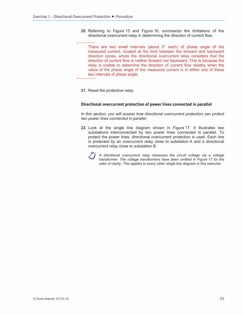
20. Referring to Figure 13 and Figure 16, summarize the limitations of the directional overcurrent relay in determining the direction of current flow.
There are two small intervals (about 5° each) of phase angle of the measured current, located at the limit between the forward and backward direction zones, where the directional overcurrent relay considers that the direction of current flow is neither forward nor backward. This is because the relay is unable to determine the direction of current flow reliably when the value of the phase angle of the measured current is in either one of these two intervals of phase angle.
21. Reset the protective relay.
Directional overcurrent protection of power lines connected in parallel
In this section, you will assess how directional overcurrent protection can protect two power lines connected in parallel.
22. Look at the single line diagram shown in Figure 17. It illustrates two substations interconnected by two power lines connected in parallel. To protect the power lines, directional overcurrent protection is used. Each line is protected by an overcurrent relay close to substation A and a directional overcurrent relay close to substation B.
a A directional overcurrent relay measures the circuit voltage via a voltage transformer. The voltage transformers have been omitted in Figure 17 for the sake of clarity. This applies to every other single line diagram in this exercise.

Exercise 1 – Directional Overcurrent Protection Procedure
26 © Festo Didactic 52174-10
Figure 17. Substations interconnected by two power lines connected in parallel. Directional overcurrent protection is used to protect the power lines.
The magnitude and phase angle of the currents and voltages measured by the relays at locations C through F under normal operating conditions are given in Table 2.
a All magnitudes are expressed as primary values, i.e., the values at the primary windings of the current and voltage transformers. Also, all phase angle values are referred to the phase angle of voltage EAN at the power source (i.e., the phase angle of voltage EAN at the power source is 0°).
Power source
Substation bus A
Substation bus B
Load
Line 150 km
0.45 /km 85°
Line 2 50 km 0.45 /km 85°
C D51 DT
51 DT
E 67
F67
315 kV
Source impedance 9.1 85°
315 kV/120 kV300 MVA
12% 85°Y-Y
Load
Exercise 1 – Directional Overcurrent Protection Procedure
© Festo Didactic 52174-10 27
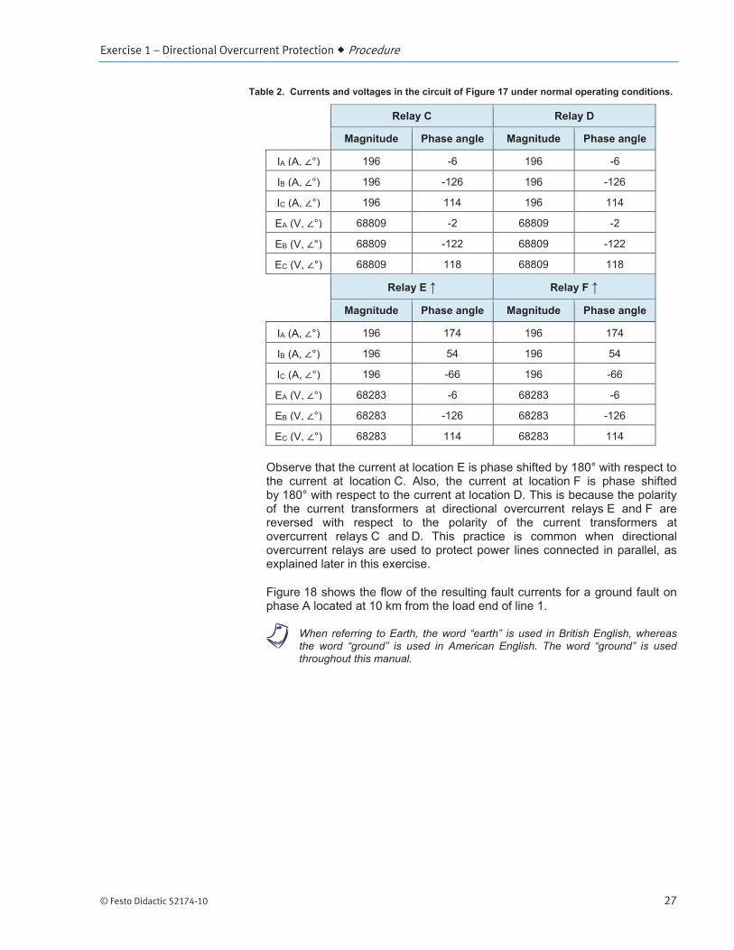
Table 2. Currents and voltages in the circuit of Figure 17 under normal operating conditions.
Relay C Relay D
Magnitude Phase angle Magnitude Phase angle
IA (A, °) 196 -6 196 -6
IB (A, °) 196 -126 196 -126
IC (A, °) 196 114 196 114
EA (V, °) 68809 -2 68809 -2
EB (V, °) 68809 -122 68809 -122
EC (V, °) 68809 118 68809 118
Relay E Relay F
Magnitude Phase angle Magnitude Phase angle
IA (A, °) 196 174 196 174
IB (A, °) 196 54 196 54
IC (A, °) 196 -66 196 -66
EA (V, °) 68283 -6 68283 -6
EB (V, °) 68283 -126 68283 -126
EC (V, °) 68283 114 68283 114
Observe that the current at location E is phase shifted by 180° with respect to the current at location C. Also, the current at location F is phase shifted by 180° with respect to the current at location D. This is because the polarity of the current transformers at directional overcurrent relays E and F are reversed with respect to the polarity of the current transformers at overcurrent relays C and D. This practice is common when directional overcurrent relays are used to protect power lines connected in parallel, as explained later in this exercise.
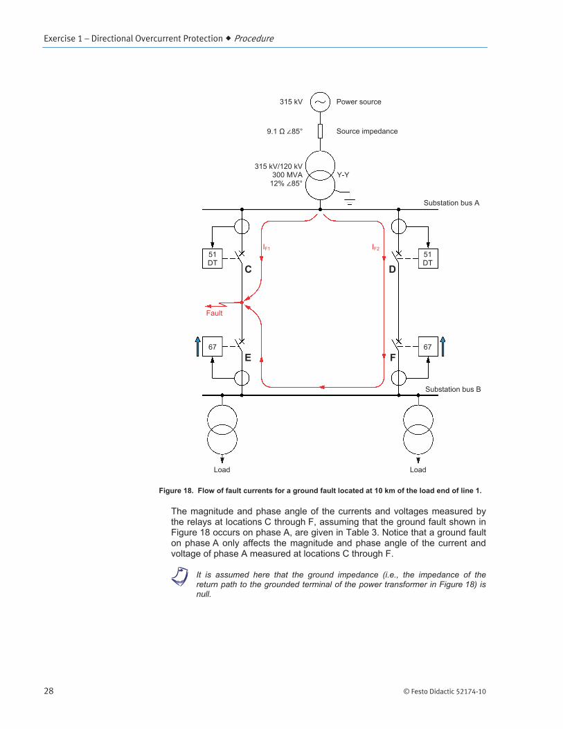
Figure 18 shows the flow of the resulting fault currents for a ground fault on phase A located at 10 km from the load end of line 1.
a When referring to Earth, the word “earth” is used in British English, whereas the word “ground” is used in American English. The word “ground” is used throughout this manual.
Exercise 1 – Directional Overcurrent Protection Procedure
28 © Festo Didactic 52174-10
Figure 18. Flow of fault currents for a ground fault located at 10 km of the load end of line 1.
The magnitude and phase angle of the currents and voltages measured by the relays at locations C through F, assuming that the ground fault shown in Figure 18 occurs on phase A, are given in Table 3. Notice that a ground fault on phase A only affects the magnitude and phase angle of the current and voltage of phase A measured at locations C through F.
a It is assumed here that the ground impedance (i.e., the impedance of the return path to the grounded terminal of the power transformer in Figure 18) is null.
IF1
Fault
IF2
Power source
Substation bus A
Substation bus B
Load
C D51 DT
51 DT
E 67
F67
315 kV
Source impedance 9.1 85°
315 kV/120 kV300 MVA
12% 85°Y-Y
Load

Exercise 1 – Directional Overcurrent Protection Procedure
© Festo Didactic 52174-10 29
Table 3. Currents and voltages in the circuit of Figure 17 under the ground fault condition (on phase A) shown in Figure 18.
Relay C Relay D
Magnitude Phase angle Magnitude Phase angle
IA (A, °) 2324 -86 1550 -84
IB (A, °) 196 -126 196 -126
IC (A, °) 196 114 196 114
EA (V, °) 41833 0 41833 0
EB (V, °) 68809 -122 68809 -122
EC (V, °) 68809 118 68809 118
Relay E Relay F
Magnitude Phase angle Magnitude Phase angle
IA (A, °) 1546 -86 1550 96
IB (A, °) 196 54 196 54
IC (A, °) 196 -66 196 -66
EA (V, °) 6958 -1 6958 -1
EB (V, °) 68283 -126 68283 -126
EC (V, °) 68283 114 68283 114
The settings of the definite-time overcurrent relays at locations C and D are given in Table 4, whereas the settings of the directional overcurrent relays at locations E and F are given in Table 5.
Table 4. Settings of the overcurrent relays at locations C and D.
Settings Value
Current threshold 400 A
Time delay 0.4 s
CT ratio 200 A / 1 A
Table 5. Settings of the directional overcurrent relays at locations E and F.
Settings Value
Characteristic angle 45°
Direction of current flow Forward
Current threshold 400 A
Time delay 0.1 s
CT ratio 200 A / 1 A
VT ratio 100 kV / 100 V
Exercise 1 – Directional Overcurrent Protection Procedure
30 © Festo Didactic 52174-10
23. In DIGSI 5, display the single-line diagram showing the connection of the protective relay to the electric power circuit.
Note the following very important point: the electric power circuit includes only one protective relay, whereas the protection system of the parallel power lines shown in Figure 17 includes four distinct protective relays.
To confirm that the protection system properly isolates the fault on line 1 (shown in Figure 18), you will:
Program the protective relay in the DIGSI 5 project to act, in turn, as each of the four protective relays in the circuit of Figure 17.
Obtain the response (i.e., whether or not the relay tripped, and if so, the trip time) of each relay under the ground fault condition shown in Figure 18.
Analyze the response of each of the four relays to reconstitute the sequence of events that occurs when the relays at locations C through F in the circuit of Figure 17 are all in operation at the same time.
In this exercise, you will first obtain the response of the overcurrent relay at locations C and D. You will then obtain the response of the directional overcurrent relay at locations E and F.
For each of the four relays to be tested, a two-step test sequence bearing the name of the relay has been predefined in the DIGSI 5 project. The magnitude and phase angle of the currents and voltages in these sequences represent those given in Table 2 and Table 3.
24. In DIGSI 5, enable fault display on the relay.
a The above setting allows the pickup and trip times of the relay to be read directly from the relay front panel display.
Operation of the overcurrent relays at locations C and D
25. In DIGSI 5, access the settings of the overcurrent protection function of the protective relay. In the Project tree area of DIGSI 5, the overcurrent protection function is called 50/51 OC-3ph-B1 or 50/51 OC-3ph-A1 and is located in protection function group VI 3ph 1. Make sure the settings of the overcurrent protection function (current threshold and time delay) match those presented in Table 4.
Set the Mode parameter to on to activate the overcurrent protection function of the protective relay.
26. In DIGSI 5, access the settings of the directional overcurrent protection function of the protective relay. In the Project tree area of DIGSI 5, the directional overcurrent protection function is called 67 Dir.OC-3ph-A1 and is located in protection function group VI 3ph 1.
Exercise 1 – Directional Overcurrent Protection Procedure
© Festo Didactic 52174-10 31
Set the Mode parameter to off to deactivate the directional overcurrent protection function of the protective relay.
The protective relay is set to operate as the overcurrent relay at location C or D.
27. In DIGSI 5, access the parameters of test sequence Testing of Relay C. This test sequence is set so that the internal relay test system emulates the currents and voltages that the overcurrent relay at location C measures when the ground fault shown in Figure 18 occurs on phase A. The test sequence consists of two steps. The first step (step 1) has a duration of 10.0 s and the second step (step 2) has a duration of 2.0 s.
The magnitude and phase angle of the currents and voltages emulated during step 1 represent those given in Table 2 (normal operating conditions). The magnitude and phase angle of the currents and voltages emulated during step 2 represent those given in Table 3 (ground fault condition shown in Figure 18).
Note that the frequency of the currents and voltages emulated by the internal relay test system during both steps of the sequence is set to 50 Hz.
Set the frequency of the currents and voltages emulated during both steps of test sequence Testing of Relay C to the frequency of your local ac power network.
28. Load the configuration to the protective relay. This is necessary because the settings of the protection function have been modified to make the protective relay operate as an overcurrent relay having the settings shown in Table 4.
29. In DIGSI 5, display the test environment of the protective relay. Start test sequence Testing of Relay C, then observe the front panel of the protective relay to see how it responds to the currents and voltages emulated by its internal relay test system.
a You may notice that the phase angle values displayed on the protective relay differ from those in the test sequence (presented in Table 2 and Table 3). This is because the protective relay assumes that the phase angle of voltage EA is 0°, the phase angle values of all other currents and voltages being adjusted accordingly.
When the protective relay picks up or trips, information (protective function that picked up and tripped the relay, relay pickup time, relay trip time, etc.) about the response of the protective relay to the test sequence is displayed on the front panel display. Use the up and down arrow buttons on the relay front panel to scroll through this information.

Exercise 1 – Directional Overcurrent Protection Procedure
32 © Festo Didactic 52174-10
Did the protective relay (i.e., the overcurrent relay at location C) operate? If so, record the trip time of the relay. Explain briefly.
Yes. The protective relay (i.e., the overcurrent relay at location C) tripped in about 400 ms because the magnitude of the emulated current for phase A (2324 A) was higher than the relay current threshold (400 A) for a time exceeding the relay time delay (0.4 s).
30. Reset the protective relay.
31. In DIGSI 5, access the parameters of test sequence Testing of Relay D. This test sequence is set so that the internal relay test system emulates the currents and voltages that the overcurrent relay at location D measures when the ground fault shown in Figure 18 occurs on phase A. Test sequence Testing of Relay D is built in the same manner as test sequence Testing of Relay C.
Set the frequency of the currents and voltages emulated during both steps of test sequence Testing of Relay D to the frequency of your local ac power network.
32. In DIGSI 5, display the test environment of the protective relay. Start test sequence Testing of Relay D, then observe the front panel of the protective relay to see how it responds to the currents and voltages emulated by its internal relay test system.
Did the protective relay (i.e., the overcurrent relay at location D) operate? If so, record the trip time of the relay. Explain briefly.
Yes. The protective relay (i.e., the overcurrent relay at location D) tripped in about 400 ms because the magnitude of the emulated current for phase A (1550 A) was higher than the relay current threshold (400 A) for a time exceeding the relay time delay (0.4 s).
33. Reset the protective relay.
Operation of the directional overcurrent relays at locations E and F
34. In DIGSI 5, access the settings of the directional overcurrent protection function of the protective relay. In the Project tree area of DIGSI 5, the directional overcurrent protection function is called 67 Dir.OC-3ph-A1 and is located in protection function group VI 3ph 1. Make sure the settings of the directional overcurrent protection function (characteristic angle, direction of current flow, current threshold, and time delay) match those presented in Table 5.
Exercise 1 – Directional Overcurrent Protection Procedure
© Festo Didactic 52174-10 33
Set the Mode parameter to on to activate the directional overcurrent protection function of the protective relay.
Observe that the direction of current flow (parameter Directional mode) is set to forward, whereas Figure 17 shows that the directional overcurrent relay at locations E and F look toward the power source, i.e., in the direction opposite to the expected direction of current flow under normal operating conditions (or reverse direction). This is because it is assumed that the polarity of the current transformers at the directional overcurrent relays is arranged in such a way that setting the direction of current flow to forward makes each relay look toward the line segment that it protects. This practice is common when directional overcurrent relays are used to protect power lines connected in parallel.
35. In DIGSI 5, access the settings of the overcurrent protection function of the protective relay. In the Project tree area of DIGSI 5, the overcurrent protection function is called 50/51 OC-3ph-B1 or 50/51 OC-3ph-A1 and is located in protection function group VI 3ph 1.
Set the Mode parameter to off to deactivate the overcurrent protection function of the protective relay.
The protective relay is now set to operate as the directional overcurrent relay at location E or F.
36. In DIGSI 5, access the parameters of test sequence Testing of Relay E. This test sequence is set so that the internal relay test system emulates the currents and voltages that the overcurrent relay at location E measures when the ground fault shown in Figure 18 occurs on phase A. Test sequence Testing of Relay E is built in the same manner as test sequence Testing of Relay C.
Set the frequency of the currents and voltages emulated during both steps of test sequence Testing of Relay E to the frequency of your local ac power network.
37. Load the configuration to the protective relay. This is necessary because the settings of the protection function have been modified to make the protective relay operate as a directional overcurrent relay having the settings shown in Table 5.
38. In DIGSI 5, display the test environment of the protective relay. Start test sequence Testing of Relay E, then observe the front panel of the protective relay to see how it responds to the currents and voltages emulated by its internal relay test system.

Exercise 1 – Directional Overcurrent Protection Procedure
34 © Festo Didactic 52174-10
Did the protective relay (i.e., the directional overcurrent relay at location E) operate? If so, record the trip time of the relay. Explain briefly.
Yes. The protective relay (i.e., the directional overcurrent relay at location E) tripped in about 100 ms, because:
the magnitude of the emulated current for phase A (1546 A) was higher than the relay current threshold (400 A).
the emulated current for phase A was flowing in the same direction as the direction of current flow set in the relay (i.e., the phase angle [-86°] of the emulated current for phase A was in the forward direction zone of the relay).
these two conditions lasted for a time exceeding the relay time delay (0.1 s).
39. Reset the protective relay.
40. In DIGSI 5, access the parameters of test sequence Testing of Relay F. This test sequence is set so that the internal relay test system emulates the currents and voltages that the overcurrent relay at location F measures when the ground fault shown in Figure 18 occurs on phase A. Test sequence Testing of Relay F is built in the same manner as test sequence Testing of Relay C.
Set the frequency of the currents and voltages emulated during both steps of test sequence Testing of Relay F to the frequency of your local ac power network.
41. In DIGSI 5, display the test environment of the protective relay. Start test sequence Testing of Relay F.
Did the protective relay (i.e., the directional overcurrent relay at location F) operate? If so, record the trip time of the relay. Explain briefly.
No. The protective relay (i.e., the directional overcurrent relay at location F) did not trip. Even if the magnitude of the emulated current for phase A (1550 A) was higher than the relay current threshold (400 A), the emulated current for phase A was flowing in the direction opposite to the direction of current flow set in the relay (i.e., the phase angle [96°] of the emulated current for phase A was not in the forward direction zone of the relay).
42. Reset the protective relay.
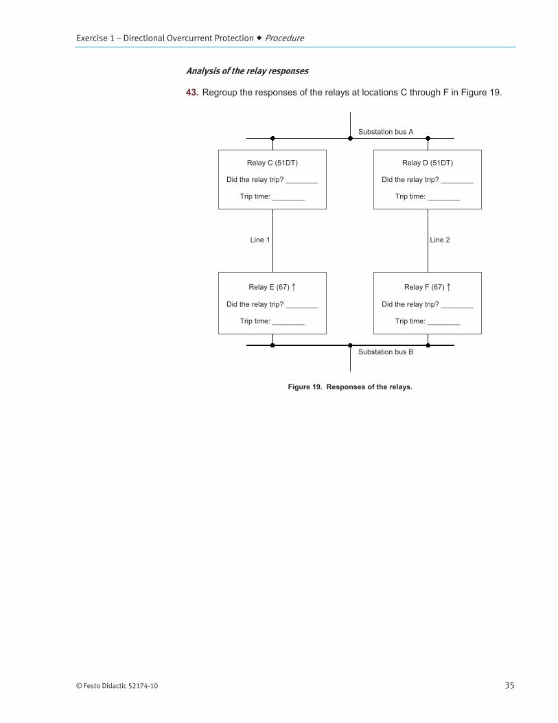
Exercise 1 – Directional Overcurrent Protection Procedure
© Festo Didactic 52174-10 35
Analysis of the relay responses
43. Regroup the responses of the relays at locations C through F in Figure 19.
Figure 19. Responses of the relays.
Substation bus A
Substation bus B
Line 1 Line 2
Relay C (51DT)
Did the relay trip? ________
Trip time: ________
Relay D (51DT)
Did the relay trip? ________
Trip time: ________
Relay E (67)
Did the relay trip? ________
Trip time: ________
Relay F (67)
Did the relay trip? ________
Trip time: ________

Exercise 1 – Directional Overcurrent Protection Procedure
36 © Festo Didactic 52174-10
Figure 19. Responses of the relays.
Using the relay responses above, reconstitute the sequence of events that should occur when the relays at locations C through F are all in operation at the same time.
The directional overcurrent relay at location E trips about 100 ms after the ground fault occurred on phase A of line 1, because fault current IF2 (refer to Figure 18) flows in the same direction as the direction of current flow set in the relay. On the other hand, the directional overcurrent relay at location F does not trip, because fault current IF2 flows in the direction opposite to the direction of current flow set in the relay.
Tripping of the directional overcurrent relay at location E immediately opens the corresponding circuit breaker, thereby interrupting fault current IF2. This, in turn, prevents the overcurrent relay at location D from tripping, because its time delay (0.4 s) largely exceeds the duration (about 100 ms) of fault current IF2.
Finally, the overcurrent relay at location C trips about 400 ms after the fault occurred. This immediately opens the corresponding circuit breaker, thereby interrupting fault current IF1.
Substation bus A
Substation bus B
Line 1 Line 2
Relay C (51DT)
Did the relay trip? Yes
Trip time: 400 ms
Relay D (51DT)
Did the relay trip? Yes
Trip time: 400 ms
Relay E (67)
Did the relay trip? Yes
Trip time: 100 ms
Relay F (67)
Did the relay trip? No
Trip time: N/A
Exercise 1 – Directional Overcurrent Protection Conclusion
© Festo Didactic 52174-10 37
How is the fault on line 1 isolated?
The fault on line 1 is isolated by the tripping of the relays at locations C and E.
How much time is required to clear the fault?
The directional overcurrent relay at location E operates in 100 ms, whereas the overcurrent relay at location C operates in 400 ms. It thus takes 400 ms to isolate the fault.
Does directional overcurrent protection isolate a fault on one of the two parallel connected lines while achieving proper discrimination? Explain briefly.
Yes. The protection isolates the fault while achieving proper discrimination. The faulty line (line 1) is disconnected and the healthy line (line 2) is left in service. Consequently, power is still available at substation bus B, thereby maintaining the availability of power at the load.
Ending the exercise
44. In DIGSI 5, restart the protective relay in the process mode to allow normal operation of the unit. Once the restart process is completed, the display of the protective relay no longer indicates that the unit is operating in the simulation mode (the words Simulation mode no longer appear on the display).
45. Close the project open in DIGSI 5 without saving the changes you made to this project.
Close DIGSI 5.
Turn the protective relay off, then disconnect it from the host computer.
Delete the copy of the project file that you opened at the beginning of this exercise.
In this exercise, you learned how to determine the direction in which an alternating current flows. You became familiar with the operation of a directional overcurrent relay, including its main settings: direction of current flow, characteristic angle, current threshold, and time delay. You saw the range of phase angle that is expected for fault currents on a given phase. You also saw that setting the characteristic angle to 45° properly aligns the forward direction and backward direction zones of a directional overcurrent relay with the expected vectors of fault currents, thereby ensuring optimal detection of the direction of current flow. You experimentally verified the angular limits of the forward and backward direction zones of a directional overcurrent relay. You learned, and experimentally verified, how directional overcurrent protection achieves discriminative protection of two parallel-connected power lines.
CONCLUSION

Exercise 1 – Directional Overcurrent Protection Review Questions
38 © Festo Didactic 52174-10
1. Why is the characteristic angle generally set to 45° in a directional overcurrent relay?
Setting the characteristic angle to 45° (typical value) properly aligns the forward and reverse direction zones of the directional overcurrent relay with the expected vectors of fault currents, thereby ensuring optimal detection of the direction of current flow.
2. Name the four main settings of a directional overcurrent relay.
The four main settings of a directional overcurrent relay are:
Direction of current flow (forward or reverse)
Current threshold
Time delay
Characteristic angle
3. How is the direction of current flow evaluated in an ac power circuit?
In an ac power circuit, one determines the direction of current flow from the phase shift between the voltage E and the current I at any given point of the circuit.
4. In a directional overcurrent relay, why is a voltage input required in addition to the current input?
In a directional overcurrent relay, a voltage input is required in addition to the current input to determine the direction of current flow via the phase shift between the voltage E and the current I.
5. Consider the two power lines connected in parallel as shown in Figure 17. Suppose that the polarity of the current transformers at each directional overcurrent relay is reversed, thereby causing each relay to look toward the load instead of toward the line segment that it protects. How could you fix this problem without changing the polarity of the current transformers?
This problem can be fixed by reversing the direction of current flow set in the directional overcurrent relay (i.e., set it to reverse).
REVIEW QUESTIONS

© Festo Didactic 52174-10 143
Bibliography
Russel Mason, C., The Art & Science or Protective Relaying, Wiley, 1964.
GEC Alsthom Measurements Limited, Protective Relays – Application Guide, 3rd ed., 1987.
Institution of Electrical Engineers, Power System Protection - Volume 2, Systems and Methods, The Electricity Training Association, 1995, ISBN 0-85296-836-1.
Alstom Grid, Network Protection & Automation Guide, 1st ed., 2011, ISBN 978-0-9568678-0-3.
Reimert, D., Protective Relaying for Power Generation Systems, 1st ed., Taylor and Francis, 2006, ISBN 978-0-8247-0700-2.
Siemens, SIPROTEC 5 – Overcurrent Protection 7SJ82/7SJ85, V4.0, 2013.


![DIGSI 5 QUICK NOTES DIGSI-5-QN0023: Deadband settings in ...DIGSI setting values compared to those used in the algorithm. [1] For most values the percentage (change) is evaluated against](https://static.fdocuments.us/doc/165x107/60651a650a733952530c038c/digsi-5-quick-notes-digsi-5-qn0023-deadband-settings-in-digsi-setting-values.jpg)