
Design of an electric motor for the propulsion of a solar boat Work... · efficiency propelling...
92
FINAL THESIS WORK INDUSTRIAL ENGINEER Design of an electric motor for the propulsion of a solar boat FINAL REPORT Author: David Macias Espinasa Director: Bauke Kalma Date: 10/07/2012 Escola Tècnica Superior d’Enginyeria Industrial de Barcelona Noordelijke Hogeschool Leeuwarden
Transcript of Design of an electric motor for the propulsion of a solar boat Work... · efficiency propelling...

FINAL THESIS WORK INDUSTRIAL ENGINEER
Design of an electric motor for the propulsion of a solar boat
FINAL REPORT
Author: David Macias Espinasa
Director: Bauke Kalma
Date: 10/07/2012
Escola Tècnica Superior d’Enginyeria
Industrial de Barcelona
Noordelijke Hogeschool Leeuwarden


Design of a motor Page 1
Summary In this text one can see the process of the preliminary design to achieve a solution for a high
efficiency propelling system for the A boat competing in the Dong solar challenge. Specifically,
this document reports the research made to achieve a solution for the mechanical design of
this motor from some features given by the foregoing electric design. To achieve this goal, a
methodical design will be performed. During this methodical design, 2 different concepts are
considered. Almost every component in both concepts is the same, as they are the
components which accomplish the main functions of the motor, which is turning electric
power into movement. They differ in the bearing disposition and the shafts shape, which will
be an important point of discussion. The aim of this report is then choosing between the two
concepts according to some requirements, like the shape of the rotor determined by the
electric design, and some wishes, like high efficiency, low weight and being easy to attach to
the boat. The calculations are made to orientate the discussion about which concept is the
best, but they are not definitive to set the final dimensions of the different components.
Before being able to discuss which one is better, some calculations need to be made, as they
make the difference within the two motors.
The bearings’ life is considered a very important point of discussion. After calculating the
forces applied on the bearings using the finite element software LISA 7.7, it is found that in
both motors, there is at least one bearing which life is too short. For this reason, needle
bearings are adopted to solve the problem in the motor 1. For the motor 2, this option cannot
be adopted so this almost discards this concept as an option.
Then the calculations for the connection between the shaft and the rims through the pins are
made. The three possible failures of the connection considered are shearing forces on the pin,
shaft tear and rim tear. The lowest safety factor found is the one concerning the shearing
forces on the pin, so if this connection fails, it will be here. Nevertheless, as this safety factor is
big enough, the connection is validated.
After that, a first simulation to know the behaviour of the shafts is made. Both shafts are
simulated under the same conditions of performance with the Solidworks Simulation Express
extension. The two principal matter of discussion are the von Mises stress and the angular
displacement of the nodes. The result of the simulation shows that the shaft in the motor 1 is
better in both items of discussion, with a safety factor for the stress of 2,54 and a
displacement of 0,2 mm.
Other items considered during the design such as assembly, fabrication and weight don’t turn
to be determinant because there is not a big difference between them in the two different
concepts.
After discussing each requirement and wish, one can see that the motor 1 is better, or at least
equal, than the motor 2 in every item discussed. For this reason, the concept chosen for the
motor is the motor 1.

Page 2 Design of a motor

Design of a motor Page 3
Index
Summary .................................................................................................................................... 1
Index........................................................................................................................................... 3
Symbols and abbreviations ......................................................................................................... 4
Assignment ................................................................................................................................. 5
0. Problem description ............................................................................................................. 7
1. Problem definition and orientation ....................................................................................... 7
1.1. Previous requirements .................................................................................................. 7
1.1.1. Context .................................................................................................................. 7
1.1.2. Directives, laws and regulations ............................................................................. 8
1.2. Requirements ............................................................................................................... 9
1.3. Specification of the wishes ............................................................................................ 9
1.4. Functions ...................................................................................................................... 10
2. Process to find solutions ....................................................................................................... 11
2.1. Methods and solutions .................................................................................................. 11
2.2. Morphologic description ............................................................................................... 12
2.3. Concepts ....................................................................................................................... 12
2.3.1. Study of the alternatives ........................................................................................ 12
2.3.2. Presentation of the concepts ................................................................................. 12
2.4. Comparison ................................................................................................................... 15
2.5. Selection of the concept ................................................................................................ 15
2.5.1. Bearing calculations ............................................................................................... 16
2.5.2. Stress calculations on the shaft .............................................................................. 25
2.5.3. Conclusion ............................................................................................................. 29
2.6. Fabrication and material combinations ......................................................................... 32
2.6.1. Material combinations ........................................................................................... 32
2.6.2. Fabrication ............................................................................................................ 33
2.7. Esthetical and ergonomic design ................................................................................... 34
3. Realisation of the motor ....................................................................................................... 36
3.1. Requirements of the different components ................................................................... 36
3.2. Calculations................................................................................................................... 38
3.2.1. Fit calculations ....................................................................................................... 38
3.2.2. Resistance calculations .......................................................................................... 45
3.2.2.1. Pin calculations ........................................................................................... 45

Page 4 Design of a motor
3.2.2.2. Rim Calculations ......................................................................................... 48
3.2.2.3. Refrigeration tubes Calculations.................................................................. 50
3.3. Materials ....................................................................................................................... 52
3.4. Preparation of the prototype ........................................................................................ 53
4. Conclusions .......................................................................................................................... 56
5. Recommendations ................................................................................................................ 57
Bibliography ................................................................................................................................ 59
Attachments/Annex .................................................................................................................... 61
A. Detail drawings .............................................................................................................. 61
B. Assembly drawings ......................................................................................................... 72

Design of a motor Page 5
Symbols and abbreviations
Symbol Description Units Tolerance interval. It’s the difference between the upper and the lower
dimension of the fabrication tolerance according to the ISO standards. -
Maxim game. Positive difference between the upper dimension of the hole and the lower dimension of the shaft.
[mm]
Maxim tightens. Negative difference between the upper dimension of the shaft and the lower dimension of the hole.
[mm]
Minim game. Positive difference between the lower dimension of the hole and the upper dimension of the shaft.
[mm]
Minim tightens. Negative difference between the lower dimension of the shaft and the upper dimension of the hole.
[mm]
External force. This symbol is used to make reference to those external forces applied to the motor.
[N]
Weight. This symbol is used to make reference to the own weight of the motor or of the component object of study.
[N]
Reaction force. This symbol, together with a sub index, is used to make reference to those forces that appear as a reaction of the interaction of the elements in the motor.
[N]
Bond moment. This symbol is used to name the moment that appear when breaking a link between components which are actually one element.
[N·m]
Bond strength. This symbol is used to name the force that appears when breaking a link between components which are actually one element.
[N]
External torque. [N·m] Diameter. This symbol is used to indicate the diameter of annuluses and
shafts. [mm]
Performance factor of the bearings. This factor is used to increase the load applied on the bearing according to the performance conditions of the machine.
-
Bearings’ static capacity of load. This parameter is the strength that one bearing can bear when it’s not spinning.
[N]
Bearings’ dynamic capacity of load. [N] Angle coefficient. Parameter that compares the influence of the axial force
applied to a bearing compared to the radial force. -
10 base logarithm of the bearings’ life. - Bearings’ life in hours. [hours] Axial coefficient for the calculation of the combined load applied on the
bearing. -
Radial coefficient for the calculation of the combined load applied on the bearing.
-
Combined load applied on the bearing. [N] Angular speed in rpm of the shaft. [rpm] Inertia of the motor. [kg·m2] Traction stress. [MPa] Mechanical resistance. [MPa] Admissible stress. It’s a parameter that depends on the characteristics of the
material. [MPa]
Safety factor. This parameter compares the real stress on the components
with the admissible stress. It must be bigger than 1. -
Compression stress. [MPa] Elastic modulus. This parameter relates the elongation of a material with the
stress it is suffering. [MPa]
Displacement. Displacement suffered by nodes in the finite elements simulations.
[mm]

Page 6 Design of a motor
Assignment This project consists of giving the best and most efficient design to a motor, respecting some
pre-established features - for example:
Outer runner motor
Electronically commutated
P = 5000 W
n = 1500 rpm
= 35 Nm
Water cooled
In addition, it has to be considered that the motor is meant to move the class A solar boat and
this can determine some aspects such as the design of certain elements that allow a good
attachment between the boat and the motor.
The process followed to obtain a solution for the problem is the typical product design
process. Below there is a brief description of each step of the process:
1. Design proposals:
a. Proposals of different constructive solutions for the motor bearing in mind all
the previous features and all the different elements needed for the motor to
have a good performance, like bearings, sealing, wire disposition, etc.
b. Settle which criteria will decide the best proposal. Some of these criteria could
be weight, size, price and difficulty to assemble.
c. Evaluation of the different solutions and decide which one fits better with the
criteria.
2. Design workout: with the solution chosen, dimensioning of all the elements
considering forces, tensions, vibrations generated, checkout of the bearings life
duration and fatigue calculations.
3. Drawings: with the correct dimensions obtained in the previous point, draw the plots
for the different non-normalized parts of the motor.

Design of a motor Page 7
0. Problem description
The Project Electric Motor for the Solarboat consists in finding a solution for the design goals:
The Solarboat needs a high efficiency motor, compact, light and able to give a maximum power
higher than the nominal during a considerable amount of time.
The solution is divided in two parts, the electrical design and the mechanical design of the
motor. The electric design will define some characteristics of the motor, like the torque or the
speed of it. The second part is the aim of this document and it tries to find a solution to
transfer the torque generated to the outside of the motor so that movement can be generated
and the solar boat can be propelled.
1. Problem definition and orientation
1.1. Previous requirements
1.1.1 Context
Nowadays, the electric motors are one of the most important parts of the industry. The
standardisation of this motors and the improvements on the building techniques, have made it
easier and cheaper to use several small motors instead of one big powerful motor with a lot of
mechanical transmissions (e.g. old factories with steam machine drive).
The motors used in the industry are usually big and heavy as they are placed in strong
machines that don’t need to be moved, so there is no need to make them smaller. In addition,
these motors are only adapted to the legislation applicable to the industry so sometimes they
don’t accomplish the laws and regulations when it comes to convenience products.
The fast development on toys, phones, computers and electronics in general have made it
necessary to create smaller motors which can satisfy their needs. These products usually use
low voltage and DC current motors, which are actually very small.
On the other hand, there is an increasing interest in the use of technologies based on
renewable energies and applications that can be given to them, such as solar energy propelled
vehicles. Despite this growing interest, the motor industry is not offering a big choice of
motors suitable for these applications (moderate power, low voltage).
There is a gap in the market for motors using low voltage, in a range of power from few
kilowatts to around ten kilowatts and designed according to the laws which involve personal
safety and use. This way they can be used to propel electric cars, bikes, boats and in general
any product needing a motor of the characteristics said above.

Page 8 Design of a motor
1.1.2 Laws, directives, and regulations
When starting a new project to develop a product, it is first necessary to have knowledge of
the different rules applicable to the product. There can be found very different types of laws
concerning: recycling, composition of the products, function, etc. The following list shows the
main European directives1 applicable to this project:
Directives and laws concerning the type of product:
Directive 2006/42/EC of the European Parliament and of the Council of 17 May 2006
on machinery, and amending Directive 95/16/EC (recast) OJ No L 157, 9 June 2006
Directive 2005/88/EC of the European Parliament and of the Council of 14 December
2005 amending Directive 2000/14/EC on the approximation of the laws of the Member
States relating to the noise emission in the environment by equipment for use
outdoors.
Directives and laws concerning products working with electricity and electronics:
Directive 2004/108/EC relating to electromagnetic compatibility and repealing
Directive 89/336/EEC OJ L 390 of 31 December 2004
Directive 2010/30/EU of the European Parliament and of the Council of 19 May 2010
on the indication by labelling and standard product information of the consumption of
energy and other resources by energy-related products OJ L 153, 18 June 2010
Directive 2006/95/EC of the European parliament and of the Council of 12 December
2006 on the harmonisation of the laws of member states relating to electrical
equipment designed for use within certain voltage limits.
Directives and laws concerning people’s safety:
Directive 2001/95/EC of the European Parliament and of the Council of 3 December
2001 on General Product Safety OJ No L 11 of 15 January 2002
Directives and laws concerning environment:
Directive 2008/98/EC of the European Parliament and of the Council of 19 November
2008 on waste and repealing certain Directives Text with EEA relevance
In addition to the current existing directives it has to be kept in mind that when there is a new
product concerning personal safety and use, new laws and directives are approved, so these
laws will also be accomplished, modifying the design if necessary.
1 EUROPEAN UNION. Policies and activities of the European Union. Leeuwarden, 2012.
[http://europa.eu/policies-activities/index_en.htm, 29th June 2012]

Design of a motor Page 9
1.2. Requirements
The design of the motor can be understood as a box with some inputs and outputs. The inputs
are all the requirements, regulations, rules, technical limitations and technical impositions. The
outputs can be understood as the wishes or the expectations about the product.
This project is composed by two subprojects. The global project “motor for the solar boat” has
a series of inputs, which are applicable to both subprojects “electric design” and “mechanical
design”. In addition some of the outputs of the electrical design are turned into inputs for the
mechanical design because they become new restrictions for it. The following illustration
pictures the global project, the subprojects and the inputs and outputs of it.
1.3. Specification of the wishes:
The wishes have to be very clear because the evaluation of how good a motor is will be made
according to the accomplishment of these desires. These desires will be kept in mind during all
the design process and often will determine some decisions:
High efficiency: high efficiency is a priority desire for the design of the motor. As it has
been said, this motor is supposed to propel the A-class Solarboat, which works with
solar energy. As the weather is unpredictable and the capacity of the batteries in the
boat are not big, the motor has to waste as least of the available energy as possible in
order to run a longer distance with the same state of load of the battery. The
mechanical design can contribute to the efficiency minimizing the losses produced by
friction between parts. The friction between the parts is avoided thanks to the
bearings, so a good design of the bearings placement will lead to a higher efficiency of
the motor itself.
Attachable to solar boat: the attachment to the solar boat is very important. The
motor has to be attached in the back part of the boat, where the propeller is.
Balance
Low weight
Assembly
Easily attachable
High efficiency
Laws
Patents
Speed of the motor
Power
Rules of the Dong solar Challenge
ELECTRIC MOTOR FOR THE SOLAR BOAT
Cooling
Outer-runner
Rotor size
MECHANICAL
DESIGN
ELECTRIC
DESIGN

Page 10 Design of a motor
Assembly: this is a common wish in all the mechanical designs. In first place, the
assembly must be possible. In addition, this assembly has to be as easy as possible. An
easy assembly means being able to assemble it by hand or using the minim number of
tools possible.
Low weight: this desire is strongly related with the global efficiency of the boat. The
Solarboat has been built with carbon fibre and epoxy polyester in order to minimize
the weight of the boat. The less weight, the less energy necessary to make it move. For
this reason, to be coherent with the design and construction of all the boat, the motor
also needs to be as light as possible. Usually, the bigger a motor, the higher the
efficiency of it, but these kinds of motors are not meant to be moved but to be placed
and not moved again. Permanent magnet motors with high power density, have a
lower efficiency, but they are smaller and the energy to move them is less, so the
global efficiency of the boat results to be higher.
Balance: this is a general desire for all the turning elements. If they are not balanced
they can create vibrations which with the time can create fatigue cracks in the parts of
the boat near to the motor attachment.
1.4. Functions
In this part, the functions of the motor will be set. Every function will be broken down into very
basic sub functions so that these functions can easily be understood. Besides, this will also help
to set the evaluation criteria for each sub function as well as the indispensable elements to
accomplish these functions.
Function Sub function Description Evaluation criteria Necessary
elements
Turn
electric
power
into
movement
Obtain electric power Access to the power supply Potential loss Wires
Convert to
electromagnetic force
Create the electromagnetic field that will
result into a force between the rotor and the
magnets
Torque generated Coils,
magnets
Commutation Alternation of the excited coils Alternation
frequency
Motor
controller
Movement Transmission of the relative movement
between the outside of the motor
Relative
displacement
between the parts
Transmission
chain
Cooling
Obtain cooling fluid Insertion of the fluid to the cooling circuit Flow Deposit,
pump
Obtain power Access to the power supply Potential loss Wires
Cool Cooling of the hot parts Temperature of
the rotor Serpentine
Evacuate cooling fluid Evacuation of the fluid from the cooling circuit Flow Deposit,
pump
Table 1. Functions and sub functions

Design of a motor Page 11
2. Process to find solutions
2.1. Methods and solutions At this point, the method used to find a solution for the mechanic design of the motor has to
be set. This design is made in many stages.
1. To start with, there has to be an analysis of the different requirements and wishes, as
any possible solution to the problem has to be able to accomplish them.
2. Analysis of the different functions and sub functions of the motor to find which
elements are indispensable to accomplish each of the functions. Also set the criteria
that will evaluate each sub function.
3. Disposition of the indispensable elements inside and outside of the motor. This will
give a first approach of the morphology of the motor.
4. Study which alternatives can give a solution to the problem keeping in mind all the
requirements, wishes, elements to be placed and the morphology given to the motor.
Choose the alternative which fits better.
Once one alternative is chosen, it will be deeply developed. In order to do this, it is necessary
to perform an iterative design:
1. Placement of the different elements in the design.
2. Resistance calculations of the different elements and calculations of the life of the
bearings.
3. Modification of those dimensions which don’t accomplish with the resistance
requirements.
4. Check if the components with the new dimensions fit with the design. In case they
don’t, modify the dimensions and go back to point 2.
After this process, the only thing left will be realise a prototype and test it. The motor will be
tested to check if the results are the expected and it will also help to know the quality of the
motor, determined according to how much the motor accomplishes the evaluation criteria
exposed on the functions definition.

Page 12 Design of a motor
2.2. Morphologic description
As it has been said, there are some shapes which have already been set in the electric design
of the motor. The shape of the rotor, together with the shape of the coils and the magnets,
determines some characteristics of the motor such as the torque and the power. For this
reason, during all the mechanical design, it has to be kept in mind that these shapes are not
modifiable and all the components have to be designed respecting these shapes.
In addition, an electric motor is a turning element. In order to make it work, the rotor has to be
axis symmetric. To keep the motor balanced, all the mechanical parts added to the basic
electric design which can intervene in the future balance of the motor, will also be axis
symmetric.
The motor also needs to be provided with an external case. The aim of this case is, on the one
hand, keep the elements of the inside isolated from the environment, and on the other hand,
provide a stiff support that allows a good attachment to the boat.
2.3. Concepts
2.3.1. Study of the alternatives
At this point it is wise to remind that the main goal of this subproject is finding a solution for
the conflict of transferring the torque generated outside of the motor and accomplish the
main function of the motor, which is turn electric power into movement.
For this reason, the goal of this point is:
Find different alternatives to solve the conflict previously exposed.
Check the viability of the solutions.
Choose the system that better fits with the requirements and wishes previously
exposed.
Previously, in the analysis of the functions of the motor, the different elements required to
accomplish each sub function have been set. These elements are the wires, magnets, coils,
motor controller and the transmission chain. Any alternative proposed has to be provided at
least with these elements.
Due to the previous design of the electric part of the motor, there is no much room to
innovate with the design. For this reason, two alternatives have been considered based on the
transmission chain, the responsible for transmitting the torque, and the one which defines
how the other components will be formed.
Alternative 1 Alternative 2
Transmission chain Front of the motor Back of the motor
Wires Back of the motor Front of the motor Table 2. Alternatives

Design of a motor Page 13
2.3.2. Presentation of the concepts Underneath one can find the assembly drawings for the two concepts:
Motor 1:
Illustration 1. Assembly motor 1
Number Component
1 Rotor
2 Coil
3 Cooling system tube 1
4 Cooling system tube 2
5 Magnet
6 Bearing 61804
7 Case 3
8 Stator
9 Rim 1
10 Shaft
11 Rim 2
12 Case 2
13 Case 1
14 Bearing 61816
15 Bearing 6304
18 Pins
Table 3. Components of the motor 1

Page 14 Design of a motor
This motor respects all the considerations previously commented. On the front part of the
shaft (see left side of the picture) the annulus of pins (18) can be seen interfering between
the shaft and the front rim (9). The back rim (11) is a redundant link and its mission is to
balance the stator, so there is no torque transmission through that rim. The bearing
housed in the rim completes the redundant link transmitting the force to the fixed case
but allowing the relative move between the rim (11) and the case (7).
Motor 2
Illustration 2. Assembly motor 2
Number Component
1 Rotor
2 Cooling system tube 1
3 Cooling system tube 2
4 Bearing 61804
5 Shaft
7 Stator
8 Magnet
9 Rim 1
10 Case 1
11 Bearing 6304
13 Coil
14 Rim 2
15 Case 3
16 Bearing 61816
18 Pins Table 4. Components of the motor 2

Design of a motor Page 15
This motor respects all the considerations previously commented. On the back part of the
shaft (see right side of the picture) the annulus of pins (18) can be seen interfering
between the shaft and the back rim (9). The front rim (14) is a redundant link and its only
mission is to balance the stator, so there is no torque transmission through that rim. The
bearing housed in the rim completes the redundant link transmitting the force to the fixed
case but allowing the relative move between the rim (15) and the case (7).
2.4. Comparison Both of the concepts are designed respecting the same pre-established features and bearing in
mind the same considerations. The main differences between them rely on practical aspects.
The bearings used in both motors are the same and in the same amount. In the motor 1, the
fixed bearing is the 6304 (15), the one with the biggest capacity of load. This bearing is the one
who holds the own weight of the rotor, refrigeration system and shaft in the axial direction, so
it preserves the life of the other weaker bearings. In the motor 2 the fixed bearing and so the
one who holds the own weight of the components is the 61804 (4), with a lower load capacity.
Before calculating the radial forces applied on the bearings, the previously said can make one
think that the bearings life of the motor 2 will be more limited that the ones in motor 1.
As it will be later explained, the shape of the shaft and the points where the torques are
applied, produce a bigger angular displacement on the second motor’s shaft than on the first.
After calculating this displacement it will be evaluated and determine either if it is excessive or
not and if it can affect negatively on the motor performance.
The transmission chain in the motor 1 is placed on the front part of the motor. As a
consequence, the wires of the coils exit have to be in the back part of the motor. This also
determines the attachment to the solar boat. This attachment can be made through the front
case (13), leaving the wires free in the back side of it.
The transmission chain in the motor 2 is placed on the back part of the motor. As a
consequence, the exit of the coils’ wires has to be in the front part of the motor. This also
determines the attachment to the solar boat. This attachment can be made through the back
case (10).
2.5. Selection of the concept Both concepts seem to be suitable to accomplish the functions. Nevertheless, in order to
achieve the best solution based on quantitative results, some calculations need to be
performed. As it has been previously said, most of the components have the same shape and
size, so they won’t make the difference. The difference between the concepts rely on the
bearings disposition and the shaft shape, so in order to orientate the selection of the concept,
the stiffness of the shafts will be quantified as well as the life of the bearings.

Page 16 Design of a motor
2.5.1. Bearing calculations
In order to calculate the bearing life, the first thing to do is determine which forces are applied
on them. That’s why first of all the free body diagram is presented to know the reactions of the
bearings on the shaft because on it is where both the external forces and reactions are
applied. Because of the bearings disposition, the system results to be statically undetermined,
so the forces and torque equilibrium equations are not enough to solve it. The real system of
forces applied on the shaft is the following, where the exterior force is “Fext” and “W” is the
own weight of the motor. All the other forces on the illustration are the reactions of the
bearings on the shaft.
Motor 1:
Illustration 3. Free body diagram of the shaft.
In order to determine the different reactions, the following simplifications are performed:
The shaft is a beam with variable section.
The places where the bearings apply their forces are substituted for a rigid support
with both axial and radial displacement forbidden.
The only exterior force applied is “Fext”
Bearing in mind these conditions, the simplified system is the following one:
Illustration 4. Simplified system forces

Design of a motor Page 17
With the system simplified, everything is ready to start solving the system:
1. Free body diagram of each element:
Illustration 5. Free body diagram of the elements
2. Now it is time to find the equilibrium equations for each element:
Element AB:
Element BC:
Element CD:
Global system:
3. The system has only 6 equations with 7 incognita, so it is not determined yet. Knowing
the torque of the shaft and supposing a gearwheel of 100 mm of diameter, the
external force can be found with this expression:

Page 18 Design of a motor
Now the system is not undetermined anymore. The results for the incognita are listed on the
following table:
28,625 Nm
58,875 Nm
701,5 N
701,5 N
500 N
201,5 N
201,5 N Table 5. Reactions and internal forces shaft motor 1
The solutions found for the reaction in B and C supports deserve special attention. The value
found for this incognita are exactly the same. Analyzing the geometry of the shaft, there are
not any relations between the distances that can make one think of a reason why this forces
should have the same value.
In order to solve this problem a finite element analysis with the software LISA 7.7 has been
made, considering the same simplifications.
The result of the beam meshed with quadratic nodes and with the loads and constraints
applied is the following one:
Illustration 6. Beam with loads and constraints
After solving the system, the software gives these values for the reactions:
Force Value
1983,79
1312,44
28,65 Table 6. Values of the reactions
The values obtained with the simulation differ a lot from the values obtained by analytical
calculation. In order to determine which values are correct, the following checkout is
performed:
An analytical calculation of a beam with two supports is made. This static problem can
be easily solved with static equations.
A simulation of the same beam with the two supports is made with the software LISA
7.7.

Design of a motor Page 19
Validation of the software:
Instead of choosing a beam with random supports, the shaft of the motor 1 has been chosen
to do the simulation, but considering the supports B and C as a single one placed at the middle
point between the two of them.
Illustration 7. Simplified beam
Analytical calculations:
Applying the static equations on the beam:
The solution for the incognita when applying the same exterior force on the edge of the
beam, are the following ones:
Force Value
1085,13
-385,13 Table 7. Values of the reactions
Simulation:
The result of the beam meshed with quadratic nodes and with the loads and constraints
applied is the following one:
Illustration 8. Beam with loads and constraints
After solving the system, the software gives these values for the reactions:
Force Value
1085,13
-385,13
Table 8. Values of the reactions

Page 20 Design of a motor
As it can be seen, the results obtained by analytical calculation and by simulation are
exactly the same. For this reason, the values chosen for the shaft are the ones obtained
with the simulation instead the ones obtained by the analytical calculations.
Motor 2
Illustration 9. Free body diagram of the shaft of the motor 2.
In order to determine the different reactions, the following simplifications are performed:
The shaft is a beam with variable section.
The places where the bearings apply their forces are substituted for a rigid support
with both axial and radial displacement forbidden.
The only exterior force applied is “Fext”
Bearing in mind these conditions, the simplified system is the following one:
With the system simplified, everything is ready to start solving the system:
1. Free body diagram of each element:
Illustration 11. Free body diagram of the elements
Illustration 10. Simplified system forces

Design of a motor Page 21
2. Now it is time to find the equilibrium equations for each element:
Element AB:
Element BC:
Element CD:
Global system:
3. The system has only 6 equations with 7 incognita, so it is not determined yet. Knowing
the torque of the shaft and supposing a gearwheel of 100 mm of diameter, the
external force can be found with this expression:
Now the system is not undetermined anymore. The results for the incognita are listed on the
following table:
28,25 Nm
17 Nm
201,92 N
201,92 N
500 N
-298, 08 N
-298,08 N Table 9. Reactions and internal forces shaft motor 1
The solutions found for the reaction in B and C supports deserve special attention. The value
found for this incognita are exactly the same. Analyzing the geometry of the shaft, there are
not any relations between the distances that can make one think of a reason why this forces
should have the same value.
In order to solve this problem a finite element analysis with the software LISA 7.7 has been
made, considering the same simplifications.

Page 22 Design of a motor
The result of the beam meshed with quadratic nodes and with the loads and constraints
applied is the following one:
Illustration 12. Beams with loads and constraints
After solving the system, the software gives these values for the reactions:
Force Value
1157,65
869,26
411,61 Table 10. Values of the reactions
The values obtained with the simulation differ a lot from the values obtained by analytical
calculation. As it has been shown before, the values obtained with the software LISA 7.7 are
more trustable than the analytical calculations. For this reason, the values chosen for the
bearings’ life calculations are the ones given by the simulation.
With the values of the forces on the bearings known, now it is time to calculate the life of
these bearings when these forces are applied on them. The procedure which will lead to the
result of their life in hours of performance will be explained in generic. The numeric results can
be found at the end of the explanation.
After having determined the loads and knowing which bearings are free and which ones are
fixed, a factor fz that considers the possible fluctuations of the loads during the service must
be applied on the loads. The following table2 recommends which value for the factor needs to
be applied:
Type of machine. Performance conditions
Machines with non fluctuant loads. Electric motors, turbines,
ventilators and centrifuge bumps.
1 – 1,2
Alternative motors (depending on the disequilibrium grade) 1,2 – 1,5
Machines with heavy fluctuant loads and impact load (presses,
laminating machines...)
1,5 - 3
Table 11. Recommendations for the load factor
For what concerns to this motor, the factor chosen is fz 2. The real loads previously
calculated will be increased by 20%.
Next step is calculating the dynamic combined load. The aim of this step is evaluate how
important is the longitudinal force compared to the axial. To do so, a series of comparisons is
done:
1. Divide the increased axial force by the load capacity of the bearing found in the
bearing’s catalogue.
2 FENOLLOSA, J. Càlcul de Màquines 2. Barcelona: ETSEIB – CPDA. 2008.

Design of a motor Page 23
2. With the value of the division, pick the value for the contact angle “e” of the following
table, interpolating if necessary. Then, divide the axial force by the radial force and
compare the value obtained with the value of the contact angle previously found.
Choose the right values for “X” and “Y” on the table. It might be necessary to
interpolate.
e
X Y X Y
0,025 0,22 1 0 0,56 2
0,04 0,24 1 0 0,56 1,8
0,07 0,27 1 0 0,56 1,8
0,13 0,31 1 0 0,56 1,4
0,25 0,37 1 0 0,56 1,2
0,5 0,44 1 0 0,56 1 Table 12. Values of combined load factors
3. With the “X” and “Y” values, the dynamic combined load can be calculated as:
Where:
is the radial factor
is the axial factor
is the radial force
is the axial force
Now it’s time to calculate nominal life of the bearing, using the following expression:
Where:
is the dynamic load capacity3
is the combined load previously found
Finally, the life in hours of the bearing can be found with the following expression:
h
n
Where:
is the speed of the shaft in rpm
3 SKF GROUP. Bearing’s catalogue. Leeuwarden, 2012.
[http://www.skf.com/portal/skf/home/products?maincatalogue=1&lang=en&newlink=1_1_1, 12th April
2012]

Page 24 Design of a motor
Now, it’s time to sum up the values for all the bearings of the design:
Motor 1:
Bearing
e
X Y P
6304* 16800 7800 0,009 0,22 0,04 1 0 1,2 2380,55 3904,91
61901 2250 980 0 0,22 0 1 0 1,2 34,38 3114182
61901 2250 980 0,07 0,27 0,05 1 0 1,2 1574,93 32,39
Table 13. Calculations of the motor 1 bearing life
Motor 2:
Bearing
e
X Y P
6304* 16800 7800 0 0,22 0 1 0 1,2 493,93 437160
61901 2250 980 0 0,22 0 1 0 1,2 1043,11 111,5
61901 2250 980 0,07 0,23 0,06 1 0 1,2 1389,18 47,2
Table 14. Calculations of the motor 2 bearing life
The values are excessively small for the bearings life. As it has been said previously, the space
available is limited, so the option of using a bigger bearing with a higher capacity of load is
discarded. In order to solve this problem it is necessary to appeal to the needle roller bearings.
Theses bearings are specially designed for these applications, where the space available is
limited and a big radial capacity of load is required. Also, these bearings are assembled with
interference so there is no need to manufacture extra section variations in the shaft and in the
hole or use extra elastic rings.
The needle bearing chosen is HK 1512, with a higher capacity of load, small dimensions, and
enough admissible speed for the application that it will be given.
Repeating the calculations of the life of the bearing for this new bearing, the results are the
following:
As it can be seen, the bearings’ life is longer in every case. Nevertheless, it has to be
considered that these bearings cannot support big axial loads and so they can’t be the fix
bearing of the couple, so maybe it’s not possible to use them in both motors.
Motor
e
X Y P
1 7650 9500 0,07 0,27 0,05 1 0 1,2 1574,93 1273,38
2 7650 9500 0 0,22 0 1 0 1,2 1043,11 4382,8
2 7650 9500 0,07 0,23 0,06 1 0 1,2 1389,18 1855,5
Table 15. Values of the needle bearings' life

Design of a motor Page 25
2.5.2. Stress calculations on the shaft
This is a very important part of the design. As it has been said before, the shaft of the motor
holds most of the external and internal forces, so it has to be stiff enough in order to ensure a
good performance. In the first place, a simulation with the tool SimulationXpress provided by
Solidworks is performed and then the results are compared to the ones found by hand
calculation.
Motor 1:
As it can be seen in the Illustration 13, the application point of the electromagnetic torque
and the one of the resistant torque are very close together. This distribution of the torques
will produce two different phenomenons. On the one hand, the shaft will only be bearing
tensions on the sections between the application points of the torques. On the other hand,
the angular displacement between the two sections where the torques are applied will be
smaller than if these points were more separated one from the other.
Illustration 13. Application points of the torques
To perform the simulation, the free extreme of the shaft has been fixed simulating the
moment where the shaft starts spinning. The receptor is not moving so the torque is
maximum. The electromagnetic torque has been substituted by forces applied on the pins
housing (see purple arrows). The value of these forces can be calculated as following:
Where
is the force on one hole
is the diameter of the annulus of the pins’ housing
is the torque
is the number of pins
Evaluating , and , the value obtained for the force is
.
Once the subjections and the loads are applied, the only thing left to run the simulation is
define a material for the shaft. The material chosen is commonly used steel for shafts, the
AISI 1045 with an elastic limit of
.

Page 26 Design of a motor
With all this data, the results of the simulation are the following:
Illustration 14. Simulation: von Mises stress shaft motor 1
This picture presents the von Mises stresses of the shaft. As it has been said before, there
are only stresses in the part of the shaft included between the points where the torqueses
are applied. The biggest von Mises tension is found on the edge of the shaft. The high
accumulation of von Mises tensions in the border of the keyway is due to its sharpness. In
addition to that, the simulation assumes that the surface of the edge of the shaft is fixed,
so it doesn’t consider that the pressure of the resistant torque is distributed uniformly
along the lateral surface of the keyway.
Considering the biggest von Mises tension, found on the edge of the keyway, the safety
factor is:
This safety factor is not considered representative of the safety of the shaft due to the
reasons previously mentioned. For this reason, the value taken to calculate the safety
factor is
which is the value of the von Mises tension on all the parts
submitted to torsion in the shaft. With this value, the safety factor is:
This safety factor is more realistic and is considered enough, so the dimensions of the shaft
won’t be modified.
The next picture illustrates the angular displacement of the shaft:
Illustration 15. Simulation: nodal displacement shaft motor 1

Design of a motor Page 27
Although the biggest value for the displacement is on the periphery of the annulus, the
displacement which is really important for the shaft performance is the one found on the
holes where the pins are held. The value of this displacement is .
Motor 2:
The application points of both motor torque and resistant torque are very separate from
each other. This produces a uniform torsion torque all along the shaft.
Illustration 16. Application points of the torques
To perform the simulation, the free extreme of the shaft has been fixed simulating the
moment where the shaft starts spinning. The receptor is not moving so the torque is
maximum. The electromagnetic torque has been substituted by forces applied on the pins
housing (see purple arrows). The value of these forces can be calculated as following:
Where
is the force on one hole
is the diameter of the annulus of the pins’ housing
is the torque
is the number of pins
Evaluating , and , the value obtained for the force is
.

Page 28 Design of a motor
Once the subjections and the loads are applied, the only thing left to run the simulation is
define a material for the shaft. The material chosen is commonly used steel for shafts, the
AISI 1045 with an elastic limit of
. With all this data, the results of the
simulation are the following:
Illustration 17. Simulation: von Mises stress shaft motor 2
This picture presents the von Mises stresses of the shaft. As it has been said before, there
are only stresses in the part of the shaft included between the points where the torqueses
are applied. The biggest von Mises tension is found on the edge of the shaft. The high
accumulation of von Mises tensions in the border of the keyway is due to its sharpness. In
addition to that, the simulation assumes that the surface of the edge of the shaft is fixed,
so it doesn’t consider that the pressure of the resistant torque is distributed uniformly
along the lateral surface of the keyway.
Considering the biggest von Mises tension, found on the edge of the keyway, the safety
factor is:
This safety factor is not considered representative of the safety of the shaft due to the
reasons previously mentioned. For this reason, the value taken to calculate the safety
factor is
which is the value of the von Mises tension on all the parts
submitted to torsion in the shaft. With this value, the safety factor is:
This safety factor is more realistic and is considered enough, so the dimensions of the shaft
won’t be modified.

Design of a motor Page 29
The following picture illustrates the relative displacement that the annulus of pins suffers
in relation to the section where the torque is applied:
Illustration 18. Simulation: nodal displacement shaft motor 2
Although the biggest value for the displacement is on the periphery of the annulus, the
displacement which is really important for the shaft performance is the one found on the holes
where the pins are held. The value of this displacement is , which is excessive.
2.5.3. Conclusion
In order to make a proper choice of the concept, there is discussion turning around the results
obtained in the bearings and shaft calculations as well as the accomplishment of the wishes
and requirements of the motor. The decision is based on both qualitative and quantitative
reasons. In order to remind them, these wishes and requirements are:
High efficiency
Attachable
Assembly
Weight
Balance
The qualitative points are the following:
High efficiency:
As it has been previously said, the mechanic design of the motor can help the motor have
a high efficiency by minimising the friction between the moving parts, or said it in another
way, with a good design of the bearings. The bearings used in both designs are the same
and in the same amount and belong to the “high efficiency bearings E2” of the SKF
company, designed to minimize the friction between parts from a 30% to a 50% respect
the regular bearings. With these bearings, the smaller the axial load is the better
performance they have. Additionally, the smaller the radial load is compared to the
capacity of the bearing, the longer the life of the bearing will be. At this point, no choice
can be made between the two motors.

Page 30 Design of a motor
Attachment:
The attachment is where one can find the biggest difference between the two concepts.
The mount designed for the motor in the Solarboat is thought to place the motor on top,
face down (with the shaft pointing to the floor). The motor 1 is easily attachable while the
motor 2 needs an extra element to be attached. This element should accomplish 2
requirements. In first place, allow the motor to hang face down and in second place be
easily attachable to the mount. Additionally, the connection shaft to the boat is done
directly on the front case, leaving the back part of the case free. This allows opening the
motor without the need of disassembling it from the boat. With this disposition, all the
cables and the cooling tubes communicate with the outside of the motor through the back
part of the case, leaving the front zone free for the shaft so that one can easily work on
that side if necessary. To sum up, the option which better fits with this requirement is the
motor 1.
Assembly:
The assembling procedure of both motors is practically equal. It has to be considered that
there are a lot of magnetic forces between the magnets and any other metallic part of the
motor so a special device has to be designed in order to be able to introduce the different
parts inside the motor avoiding the contact between the magnets and these parts due to
the magnetic forces. At this point, no choice can be made between the two motors.
Weight:
Weight can be a differential factor when choosing a model. It has to be considered that
weight on the different elements of the Solarboat is closely watched so that the maximum
amount of energy can be saved. For this reason, the right choice of the motor elements
placements will contribute to minimize the dimensions of some components so that the
final weight of the global set is smaller.
Balance:
The shafts in both motors are small due to the limited space available in the inside’s hole
of the rotor. Considering that there is the need of a cooling system and bearings, the space
left for the shaft is very small, so there is no chance to make the shaft thicker and stiffer.
This is why the motor 1 has advantage in this part. The part of the shaft submitted to
torsion is outside of the rotor’s hole, so it can be made thicker without compromising any
other dimensions, which will provide a better balance as it will not suffer too many relative
displacements. Meanwhile, the shaft of the motor 2 might be stiff enough to support the
torsion forces but the displacement can result to be too big. Increasing the thickness of the
shaft in order to avoid that displacement would mean using weaker bearings, so what
would be gained on one side would be lost on the other side.

Design of a motor Page 31
The results of the calculations are summarized in the next table:
Motor 1 Motor 2 Units
Life of the bearing 61304* 3904,91 437160 [hours]
Life of the bearing 61901(1) 3114182 111,5 [hours]
Life of the bearing 61901(2) 32,39 47,2 [hours]
Minimum safety factor to the shaft failure 2,54 1,83 -
Maximum nodal displacement of the shaft 0,2 1,3 [mm] Table 16. Summary of the bearing and shaft calculations
The results obtained for the bearings life are determinant. In both concepts, the bearing
61304* has a very long life, so it will not be discussed. The main difference between the
bearings comes when talking about the life of the other two bearings. The bearing 61901(2) for
the motor 1 and the 61901(1) for the motor 2 are the free bearing of the set of bearings, so
even if they have a short life, they can always be substituted for needle bearings, with a big
capacity of load in the radial direction in a small size bearing. The difference comes when
talking about the fix bearing in the motor 1, the 61901(1), and the 61901(2) for the motor 2.
Because of being fixed, this bearings support axial forces and cannot be substituted by needle
bearings. For this reason, the result obtained in these calculations is determinant. The motor 1
has a very long life, while the life of the fix bearing in the motor 2 is very short. As there is no
solution for this issue, the best solution for the problem at this point is the motor 1.
When talking about the stiffness of the shaft, the results are clear too. The shaft in the motor 1
is much stiffer than the one in the motor 2. Even if the safety factor obtained for the motor 2
ensures that the shaft won’t break, the safety is very low. This will contribute to the good
balance of the motor. This point also gives advantage to the motor 1 in front of the motor 2.
In addition, as it has been previously said, the attachment of the motor is one of the most
important requirements. It has to be easily attachable, as during the race it might be necessary
to do so in order to fix the boat without losing any time. To attach the motor 2, the boat needs
to be provided with a new mounting system or with an additional element. This will add more
weight to the boat, and weight is very close regarded in this project.
For all these reasons the solution chosen is the first alternative, the motor 1

Page 32 Design of a motor
2.6. Fabrication and material combinations At this point, the most suitable fabrication process will be decided. Various possibilities of
materials for the different components will be decided. The fabrication process will be split in
the fabrication of a prototype and a fabrication in series if it had to happen.
In the first place, to decide a fabrication process it is necessary to discuss which materials
would be suitable for each component. Once this is done, one can decide which the adequate
technique is: injection, casting, chip removal, etc.
2.6.1. Material combinations Besides the mechanical characteristics different materials can offer, often the choice of a
material is based in its esthetical or sensations it can create (e.g. metal to give sensation of
cold, polymers to give bright warm colours, etc.).
Elements without an esthetical function:
This group concerns all those elements that cannot be seen from outside the motor, like
shaft, coils, magnets, etc. These elements mainly perform mechanical or electrical
functions so the choice of these materials will be based in terms of physical properties. The
next table summarises the materials which can be suitable for each element:
Element Requirements of the material Suitable materials
Coil High electrical conduction Copper
Magnet Ferromagnetism Cast iron
Rotor High magnetic conduction Steel
Stator Stiffness Aluminium, iron,
stainless steel
Shaft Stiffness Aluminium, iron,
stainless steel
Cooling High heat transfer coefficient Copper, iron Table 17. Material suitable for each element
The final decision of the element will be made after the resistance calculations are made.
Other elements:
This group concerns those elements that can be seen from outside the motor and that can
influence by their shape, colour or texture to the perception of the user towards the
motor. The main elements in this group are those who compose the case of the motor.
Besides accomplishing the conditions of mechanical resistance they also need to
accomplish esthetical functions.
Design of a motor Page 33
Element Requirements of the material Suitable materials
Case Sensation of stiffness,
cleanness and possibility of painting
Polymers, steel, cast iron,
aluminium
Wire cover Isolating Polymers, rubber
Cooling tubes
High heat transfer coefficient Copper
Shaft Stiffness Aluminium, iron,
stainless steel Table 18. Material suitable for each element
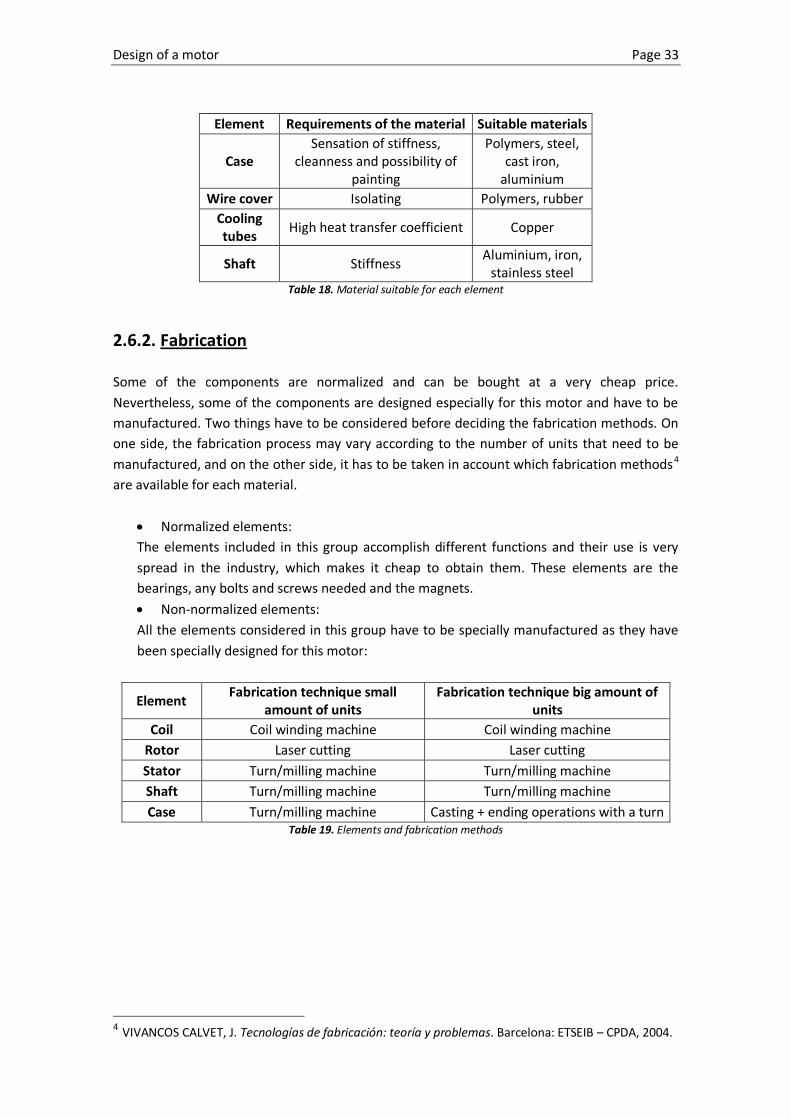
2.6.2. Fabrication Some of the components are normalized and can be bought at a very cheap price.
Nevertheless, some of the components are designed especially for this motor and have to be
manufactured. Two things have to be considered before deciding the fabrication methods. On
one side, the fabrication process may vary according to the number of units that need to be
manufactured, and on the other side, it has to be taken in account which fabrication methods4
are available for each material.
Normalized elements:
The elements included in this group accomplish different functions and their use is very
spread in the industry, which makes it cheap to obtain them. These elements are the
bearings, any bolts and screws needed and the magnets.
Non-normalized elements:
All the elements considered in this group have to be specially manufactured as they have
been specially designed for this motor:
Element Fabrication technique small
amount of units Fabrication technique big amount of
units
Coil Coil winding machine Coil winding machine
Rotor Laser cutting Laser cutting
Stator Turn/milling machine Turn/milling machine
Shaft Turn/milling machine Turn/milling machine
Case Turn/milling machine Casting + ending operations with a turn Table 19. Elements and fabrication methods
4 VIVANCOS CALVET, J. Tecnologías de fabricación: teoría y problemas. Barcelona: ETSEIB – CPDA, 2004.

Page 34 Design of a motor
2.7. Ergonomic and esthetical design
2.7.1. Ergonomic design
In order to create a good ergonomic design it is necessary to do an analysis of the needs of the
different users of the motor. These users are not only the “volunteer users” but also those
who can be affected by the use or manipulation of the motor.
Operators of the motor:
o Installer of the motor: even this is not the main user of the motor, is the user
which needs the motor to be adapted to his needs as he is manipulating it. This
user expects from the motor to be easily attachable to the boat, easily coupled
with the propeller and easily connected to the power supply.
o Driver of the solar boat: the driver expects the motor to work properly. He
expects to have a smooth performance and a proper response whenever he needs
to. He also expects the motor to be silent so that it doesn’t create discomfort due
to the long time exposure to the noise.
Third parties affected by the use of the motor:
o Competition inspectors: the competition inspectors want the motor to accomplish
with the different rules that can affect the motor, such as size, maxim or minim
power and safety.
o Other competitors of the race: they expect the motor to accomplish all the rules
of the challenge so that they don’t have a clear disadvantage in front of them.
Once all the users involved are analysed, it is time to set which ergonomic needs they have
when it comes to physical and mental demands when using the motor.
Physical demands:
o The motor has to be handled by an average adult. Consequently the weight needs
to be appropriate and the shape has to offer a way to be held. The user has to be
able to move it from one side to the other without feeling physical tiredness.
o The motor has to be attached by an average adult. For this reason the motor has
to be provided with an easy system of attachment to the boat so that the user
doesn’t feel tired when attaching it.
o The motor has to be easily plugged to the power supply. The user mustn’t receive
an electric shock when plugging the motor to the power supply.
Mental demands:
o The motor has to be handled by an average adult without getting nervous or
feeling psychological fatigue because of finding difficulties to hold the motor or to
move it.
o The motor has to be attached by an average adult without getting nervous or
feeling psychological fatigue because of finding difficulties to attach it.
o The motor has to be easily plugged to the power supply. The user mustn’t feel
nervous or psychologically tired because he is unable to plug the motor to the

Design of a motor Page 35
power supply. Additionally, the appearance of the plug has to transmit the
confidence to the user that we will not get injured when plugging it.
2.7.2. Esthetical design The motor is intended to propel the solar boat. The choice of a motor is based on its features
and not on its appearance. Nevertheless, there are some requirements concerning esthetical:
It has to be easy to recognise the product as a motor. This means using, for example,
round shapes for the case.
The case should be made of a material which allows to be painted. The paint will cover
any imperfections on the surface of the motor giving a homogeneous and pleasant
look.
All the components must look in good conditions. The different components must be
protected against the rust. Even if the rust layer is not deep and it doesn’t compromise
the resistant characteristics of the different elements, the presence of this rust creates
a lack of confidence of the user towards the product.
The case has to be provided with a small plate with the main features (e.g. power,
frequency, nominal voltage, torque...) of the motor written. This will help identifying
the motor and its main features easily.

Page 36 Design of a motor
3. Realisation of the motor
3.1. Requirements of the different components
Rotor: the rotor dimensions are pre-established and satisfy the calculus of electromagnetic
torque, nominal speed and power. These dimensions decide some other important
dimensions such as the inner diameter of the stator, the disposition of the magnets, and of
course, the final dimensions of the motor case. The magnetic lines have to be driven by the
rotor lamination in order to present magnetic saturation, so the central hole of it has to
respect a maximum diameter, which determines the available room for the shaft, the
cooling system and bearings.
Illustration 19. Rotor
Stator: the stator dimensions are defined by the outsider diameter of the rotor. This is an
out runner motor, so the stator is a turning element that receives the electromagnetic
torque and transfers it to the shaft into mechanical torque. For this reason, it’s a very
important element. It has to be balanced in order to avoid vibrations, it has to be strong
enough so that it can transfer the torque properly, and it needs to be capable of holding
the magnets.
Shaft: the shaft is a critical element in the design. Both internal and external solicitations
rely on it. The dimensioning has been made considering that it has to be housed through
the hole of the inner tube of the cooling system. Additionally, various section variations
have been made to allow a good housing for the bearings. Finally, there are six holes for
introducing six pins which are going to be responsible of the torque transmission.
Torque transmission: the torque is transferred from the stator to the receptor through the
following chain: the stator has one annulus with threaded holes in each flat side of it,
where two rims are assembled. One of these rims is just for avoiding the shaft jutting out
while the other one has a six-hole annulus where the pins that transmit the torque to the
shaft are held. In one of the concepts the rim that transmits the torque is in the frontal
part of the motor while in the other design it’s in the back.

Design of a motor Page 37
Illustration 20. Torque transmission through the elements in motor 2
Cooling: the cooling system consists of two concentric tubular shafts. The first one, made
of a high thermal conduction coefficient, is in contact with the rotor. The second one is
assembled inside the first one and it has a double serpentine around it through which the
cooling liquid can run. Additionally, inside the second tubular shaft there are two inside
section changes where the bearings can be placed.
Bearings: the bearings are chosen from the SKF company catalogue. Due to the character
of the external solicitations, the reactions over the shaft are mostly in the radial direction.
That’s why the bearings chosen are of the kind “Single row deep groove ball bearings”,
with a big capacity of bearing radial forces and an acceptable behaviour in front of small
axial forces such as the weight of the rotor.
Case: the case is made of three parts. The front part provides the motor with its basic
shape while the back part just closes it. Additionally, in the back part of the case a tubular
element is placed. This element contains the holes through which all the cables and
refrigeration tubes will exit of the motor.
Fits: in the motor there are a lot of elements that interact, so some dimensions of these
elements need determined tolerances that assure a good assembling. The ISO tolerance
system is used to assign the tolerance to these dimensions. For the fits between some of
the normalized and non-normalized elements, the recommendations of the manufacturer
are adopted while for the rest of the fits the following procedure is followed: at the
beginning there is an evaluation of the type of fits needed for each union and next a
couple of ISO values are taken (see Table 1). Once they are chosen, the calculi of the
resulting fits are made (maximum and minimum game or tighten…). The following pages
collect the results for the calculi. There can also be seen an extract with the recommended
fits by the international organisation for standardization (ISO).

Page 38 Design of a motor
3.2. Calculations
At this point, two kinds of calculations will be made. The first calculations are those which
warranty the correct placement and fits of the parts and as a result, the correct placement and
alignment of the shaft. These calculations are the tolerance calculations.
The second group of calculations are resistance calculations. These calculations are used to
determine the dimensions with which the different elements subject to forces and torques will
be stiff enough to accomplish their function without breaking.
3.2.1. Tolerance calculations
In order to calculate the different fits between the elements, the next procedure is followed:
at the beginning there is an evaluation of the type of fits needed for each union and next a
couple of ISO values are taken (see Table 20). Once they are chosen, the calculi of the resulting
fits are made (maximum and minimum game or tighten…). The following pages collect the
results for the calculi. There can also be seen an extract with the recommended fits by the
international organisation for standardization (ISO).
ISO FITS ~first preference
ISO SYMBOL DESCRIPTION
Hole Basis Shaft Basis
H11/c11 C11/h11 Loose running fit for wide commercial tolerances or allowances on external
members
H9/d9 D9/h9 Free running fit not for use where accuracy is essential, but good for large
temperature variations, high running speeds, or heavy journal pressure
H8/f7 F8/h7 Close running fit for running on accurate machines and accurate location at
moderate speeds and journal pressures.
H7/g6 G7/h6 Sliding fit not intended to run freely, but to move and turn freely and locate
accurately
H7/h6 H7/h6 Locational clearance fit provides snug fit for locating stationary parts; but can be
freely assembled and disassembled.
H7/k6 K7/h6 Locational transition fit for accurate location. A compromise between clearance
and interference.
H7/n6 N7/h6 Locational transition fit for parts requiring rigidity and alignment with prime
accuracy of location but without special bore pressure requirements
H7/p6 P7/h6 Locational interference fit for parts requiring rigidity and alignment with prime
accuracy of location but without special bore pressure requirements
H7/s6 S7/h6 Medium drive fit for ordinary steel parts or shrink fits on light sections, the tightest
fit usable with cast iron
H7/u6 U7/h6 Force fit for parts which can be highly stressed or for shrink fits where the heavy
pressing force required are impractical.
Table 20. First preference recommended fits

Design of a motor Page 39
ISO FITS ~ second preference
ISO SYMBOL
Description Hole
Basis
Shaft
Basis
H8/e8 E9/h9 Medium running fit (much clearance)
H8/h9 H8/h9 Sliding fit (parts slightly moveable)
H7/d9 D9/h6 Wide loose running fit (ample clearance)
H7/e8 E8/h6 Medium running fit (much clearance)
H7/f7 F7/h6 Running fit (parts easily moveable)
H7/j6 J7/h6 Locational transition fit (parts movable by hand, a hammer may be necessary)
H7/m6 M7/h6 Driving/locational transition fit (parts have to be driven in by hammer or press)
H7/r6 R7/h6 Press/snug fit (parts can only be assembled by heating the part with the hole or
chilling the shaft etc.)
Table 21. Second preference recommended fits
Underneath the calculations for the different elements fits are presented:
Illustration 21. Fits drawing

Page 40 Design of a motor
• Fit A: the A dimension refers to the fit between the bearings 61804 and the shaft. The
bearing manufacturer warranties a tolerance H7 to the internal ring of the bearing. Then,
following its recommendations, using a k6 tolerance for its placement on the shaft the
result is an undetermined fit. The assembling might be done with a hammer.
Dimension
[mm]
Tolerance IT [µm] Upper deviation Lower deviation
Shaft Hole Shaft Hole Shaft Hole Shaft Hole
20 k6 H7 13 21 - - 2 0
Table 22. Tolerances and deviations.
Upper value Lower value
JM AM Shaft Hole Shaft Hole
20,015 20,021 20,002 20 0,019 0,015
Table 23. Extreme values and resulting fit.
• Fit C: the C dimension refers to the fit between the bearings 61804 and their housing.
According to the manufacturer, the tolerance for the housing should be H8 because the
insides ring of the bearing is made with a j6 tolerance, so the result is an undetermined fit.
The assembling might be done with a hammer.
Dimension
[mm]
Tolerance IT [µm] Upper deviation Lower deviation
Shaft Hole Shaft Hole Shaft Hole Shaft Hole
32 h7 H8 13 21 - - 2 0
Table 24. Tolerances and deviations.
Upper value Lower value JM AM
Shaft Hole Shaft Hole
20,015 20,021 20,002 20 0,019 0,015
Table 25. Extreme values and resulting fit.
• Fit D: the D dimension refers to the fit between both tubular cooling shafts. Both shafts
must have a tight fit because they are holding the rotor, which is the one generating the
torque. A bad fit could generate vibrations and in general, a bad performance of the motor.
These are the reasons why the selected fit is H6/k5.
Dimension
[mm]
Tolerance IT [µm] Upper deviation Lower deviation
Shaft Hole Shaft Hole Shaft Hole Shaft Hole
40 k5 H6 11 16 - - 2 0
Table 26. Tolerances and deviations.
Upper value Lower value JM AM
Shaft Hole Shaft Hole
40,013 40,016 40,002 40 0,014 0,013
Table 27. Extreme values and resulting fit.
Design of a motor Page 41
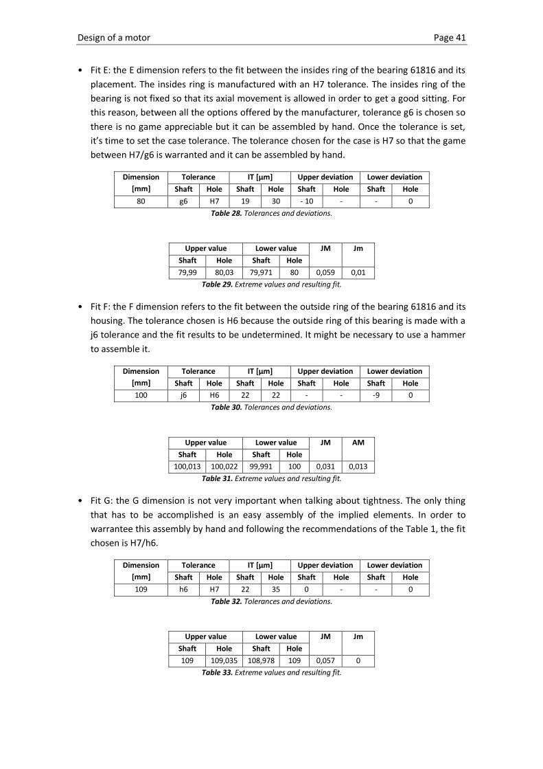
• Fit E: the E dimension refers to the fit between the insides ring of the bearing 61816 and its
placement. The insides ring is manufactured with an H7 tolerance. The insides ring of the
bearing is not fixed so that its axial movement is allowed in order to get a good sitting. For
this reason, between all the options offered by the manufacturer, tolerance g6 is chosen so
there is no game appreciable but it can be assembled by hand. Once the tolerance is set,
it’s time to set the case tolerance. The tolerance chosen for the case is H7 so that the game
between H7/g6 is warranted and it can be assembled by hand.
Dimension
[mm]
Tolerance IT [µm] Upper deviation Lower deviation
Shaft Hole Shaft Hole Shaft Hole Shaft Hole
80 g6 H7 19 30 - 10 - - 0
Table 28. Tolerances and deviations.
Upper value Lower value JM Jm
Shaft Hole Shaft Hole
79,99 80,03 79,971 80 0,059 0,01
Table 29. Extreme values and resulting fit.
• Fit F: the F dimension refers to the fit between the outside ring of the bearing 61816 and its
housing. The tolerance chosen is H6 because the outside ring of this bearing is made with a
j6 tolerance and the fit results to be undetermined. It might be necessary to use a hammer
to assemble it.
Dimension
[mm]
Tolerance IT [µm] Upper deviation Lower deviation
Shaft Hole Shaft Hole Shaft Hole Shaft Hole
100 j6 H6 22 22 - - -9 0
Table 30. Tolerances and deviations.
Upper value Lower value JM AM
Shaft Hole Shaft Hole
100,013 100,022 99,991 100 0,031 0,013
Table 31. Extreme values and resulting fit.
• Fit G: the G dimension is not very important when talking about tightness. The only thing
that has to be accomplished is an easy assembly of the implied elements. In order to
warrantee this assembly by hand and following the recommendations of the Table 1, the fit
chosen is H7/h6.
Dimension
[mm]
Tolerance IT [µm] Upper deviation Lower deviation
Shaft Hole Shaft Hole Shaft Hole Shaft Hole
109 h6 H7 22 35 0 - - 0
Table 32. Tolerances and deviations.
Upper value Lower value JM Jm
Shaft Hole Shaft Hole
109 109,035 108,978 109 0,057 0
Table 33. Extreme values and resulting fit.
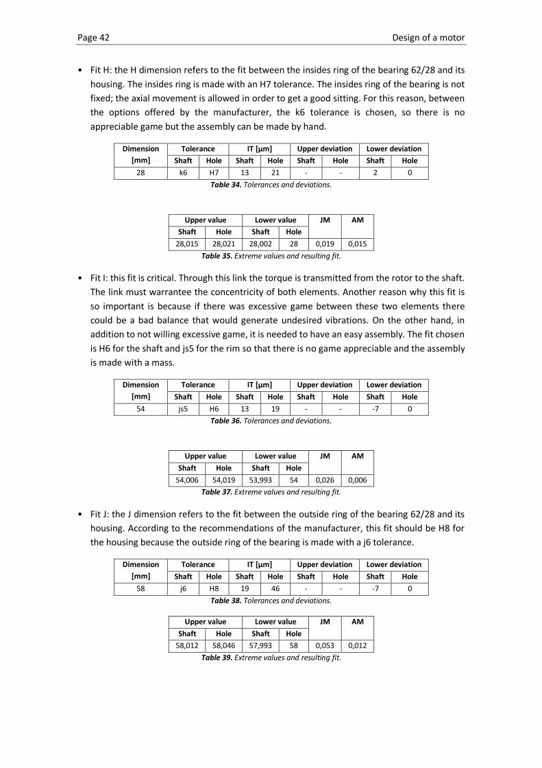
Page 42 Design of a motor
• Fit H: the H dimension refers to the fit between the insides ring of the bearing 62/28 and its
housing. The insides ring is made with an H7 tolerance. The insides ring of the bearing is not
fixed; the axial movement is allowed in order to get a good sitting. For this reason, between
the options offered by the manufacturer, the k6 tolerance is chosen, so there is no
appreciable game but the assembly can be made by hand.
Dimension
[mm]
Tolerance IT [µm] Upper deviation Lower deviation
Shaft Hole Shaft Hole Shaft Hole Shaft Hole
28 k6 H7 13 21 - - 2 0
Table 34. Tolerances and deviations.
Upper value Lower value JM AM
Shaft Hole Shaft Hole
28,015 28,021 28,002 28 0,019 0,015
Table 35. Extreme values and resulting fit.
• Fit I: this fit is critical. Through this link the torque is transmitted from the rotor to the shaft.
The link must warrantee the concentricity of both elements. Another reason why this fit is
so important is because if there was excessive game between these two elements there
could be a bad balance that would generate undesired vibrations. On the other hand, in
addition to not willing excessive game, it is needed to have an easy assembly. The fit chosen
is H6 for the shaft and js5 for the rim so that there is no game appreciable and the assembly
is made with a mass.
Dimension
[mm]
Tolerance IT [µm] Upper deviation Lower deviation
Shaft Hole Shaft Hole Shaft Hole Shaft Hole
54 js5 H6 13 19 - - -7 0
Table 36. Tolerances and deviations.
Upper value Lower value JM AM
Shaft Hole Shaft Hole
54,006 54,019 53,993 54 0,026 0,006
Table 37. Extreme values and resulting fit.
• Fit J: the J dimension refers to the fit between the outside ring of the bearing 62/28 and its
housing. According to the recommendations of the manufacturer, this fit should be H8 for
the housing because the outside ring of the bearing is made with a j6 tolerance.
Dimension
[mm]
Tolerance IT [µm] Upper deviation Lower deviation
Shaft Hole Shaft Hole Shaft Hole Shaft Hole
58 j6 H8 19 46 - - -7 0
Table 38. Tolerances and deviations.
Upper value Lower value JM AM
Shaft Hole Shaft Hole
58,012 58,046 57,993 58 0,053 0,012
Table 39. Extreme values and resulting fit.

Design of a motor Page 43
Illustration 22. Pins fit detail
• Fit K: the K dimension refers to the fit between the pins that transmit the torque and the
holes in the shaft where they are held. This is maybe the most important fit of all because
the pins are resistors elements and they are responsible for the good performance of the
motor. It is then necessary to have a fit with not much game, so that there is not an impact
between the holes’ walls and the pins during the acceleration and braking. At the same
time the fit needs to avoid vibrations due to small relative movements between turning
elements and friction between contact surfaces. The pins are manufactured according to
DIN6325 so the manufacturing tolerance adopted for the pins diameter is m6. Then, the
tolerance chosen for the shaft holes is H7 so that the result is an undetermined fit. The
assembly must be done with a mass but the elements involved in the union are not
destroyed.
Dimension
[mm]
Tolerance IT [µm] Upper deviation Lower deviation
Shaft Hole Shaft Hole Shaft Hole Shaft Hole
6 m6 H7 8 12 - - 4 0
Table 40. Tolerances and deviations.
Upper value Lower value JM AM
Shaft Hole Shaft Hole
6,012 6,012 6,004 6 0,008 0,012
Table 41. Extreme values and resulting fit.

Page 44 Design of a motor
• Fit L: this L dimension refers to the fit between the pins that transmit the torque and the
holes in the rim where they are held. This is probably the most important fit of all because
the pins are resistor elements and they are responsible for the good performance of the
motor. It is then necessary to have a fit without any game, so that there is not an impact
between the holes’ walls and the pins during the acceleration and breaking. At the same
time the fit needs to avoid vibrations due to small relative movements between turning
elements and friction between contact surfaces. The pins are manufactured according to
DIN6325 so the manufacturing tolerance adopted for the pins diameter is m6. Then, the
tolerance chosen for the rim holes is H7 so that the result is a fit without any game. The
assembly must be done with a mass but the elements involved in the union are not
destroyed.
Dimension
[mm]
Tolerance IT [µm] Upper deviation Lower deviation
Shaft Hole Shaft Hole Shaft Hole Shaft Hole
6 m6 H7 8 12 - - 4 0
Table 42. Tolerances and deviations.
Upper value Lower value JM AM
Shaft Hole Shaft Hole
6,012 6,012 6,004 6 0,008 0,012
Table 43. Extreme values and resulting fit.
Illustration 23. Cotter fit detail
• Fit M: the M dimension refers to the fit between the two tubular shafts responsible for the
cooling. This union transmits the torque to a fixed support, avoiding a spin of the rotor and
transmitting the reaction torque to the shaft. The fit chosen is H7/j6, so that the assembly
can be made with a mass and the tightness is warranted.
Dimension
[mm]
Tolerance IT [µm] Upper deviation Lower deviation
Shaft Hole Shaft Hole Shaft Hole Shaft Hole
6 j6 H7 8 12 - - -2 0
Table 44. Tolerances and deviations.
Upper value Lower value JM AM
Shaft Hole Shaft Hole
6,006 6,012 5,998 6 0,014 0,006
Table 45. Extreme values and resulting fit.

Design of a motor Page 45
In order to get a global view of the different fits, here one can find a resume table with all the
values previously exposed:
Dimension Nominal Tolerance Type of
adjustment
Max.
game
Min. Game/
Max. tighten Shaft Hole
A 20 k6 H7 Undetermined 0,019 0,015
B - - - - - -
C 32 h7 H8 Game 0,052 0
D 40 k5 H6 Undetermined 0,014 0,013
E 80 g6 H7 Game 0,059 0,01
F 100 j6 H6 Undetermined 0,031 0,013
G 109 h6 H7 Game 0,057 0
H 28 k6 H7 Undetermined 0,019 0,015
I 54 js5 H6 Undetermined 0,026 0,006
J 58 j6 H8 Undetermined 0,053 0,012
K 6 m6 H7 Undetermined 0,008 0,012
L 6 m6 H7 Undetermined 0,008 0,012
M 6 j6 H7 Undetermined 0,014 0,006
Table 46. Resume of all the fit values.
3.2.2. Resistance calculations
These calculations are used to determine the dimensions with which the different elements
subject to forces and torques will be stiff enough to accomplish their function without
breaking. The following pages show the calculations for the pins, the rim, and the cooling tube.
3.2.2.1. Pin calculation Just like it was said before, the transmission of the torque is performed by the physical
interference between the shaft and the rim through an annulus of 6 pins. Hereby one can see
the resistant calculi of the unions:
Safety to shearing forces on the pin section:
Illustration 24. Forces on the pins
Fext/2
Fext/2

Page 46 Design of a motor
The torque of the motor evolves following the next expression5:
The worst situation for the pins, then, is when the motor is accelerating from speed zero
and the resistant torque is maxim. The torque creates two equal forces on the opposite
sense, which create a shearing force on the pin section. Once the torque is known, the
force applied on the centre of the pin can be found using the following expression:
Where:
is the torque of the motor
is the diameter of the annulus where the pins are held
The exterior force, considering that the pins are placed in an annulus of , is
.
To find the shearing force of the resistant section of the pin it is now only necessary to
divide the force applied on one pin and divide it by the area of the section. The resulting
expression is the following:
Where:
is the force that all the pins together bear in their section
is the number of pins
is the number of sections of each pin supporting the shearing force
is the area of the resistant section of one pin
Substituting the parameters by , ,
the shearing force
has the value
.
Then, it is necessary to compare the obtained value of the shearing force with the
admissible value for the material.
The pins are normalized according to DIN6325 and they are manufactured in the material
BO-1 (1.2510), with
. In isotropic materials, the shearing admissible force is
around the 60% of the value of the pulling admissible force. The value taken to compare
with the value obtained before is
.
When comparing the values the result is , so the pins are not cut.
5 JUANA SARDÓN, J. Física general. Volumen I. 2nd edition. Madrid: Pearson Educación S.A. 2007.

Design of a motor Page 47
Once it is checked that the pin will resist, it is time to calculate the safety factor for this
union:
Safety to the shaft tear:
The following calculations are made to calculate the pulling stress that the pins create on
the shaft. In order to calculate this force the next expression is used:
Where:
is the force applied on the pin’s area A
is the projected area of the pin that pulls the shaft
is an experimental parameter and its value for calibrated pins is 2,56
Changing the parameters for their value the following value for the stress is found:
Then it is necessary to compare the obtained value of the shearing force with the
admissible value for the material.
The material chosen for the shaft is AISI 10457 with
. When comparing the
values, the result is , so the shaft doesn’t tear.
Once it is checked that the shaft will resist, it is time to calculate the safety factor for this
union:
Observing the safety factor obtained and before calculating the other types of possible
failures of the union, one can say that the safety factor is too high. This can be translated
into a decreasing of the diameter and the amount of pins in the union as well as some of
the shaft dimensions, but as the pins are cheap elements and this union is very important,
no modifications will be made.
Safety to the rim tear:
The following calculations are made to calculate the pulling stress that the pins create on
the rim. In order to calculate this force the next expression is used:
Where:
is the force applied on the pin’s area A
is the projected area of the pin that pulls the shaft
is an experimental parameter and its value for calibrated pins is 2,58
6 AYNETO, A.; MARIMON, F.; ROURE, F. “Resistencia de Materiales” Barcelona, ETSEIB – CPDA, 1999
7 RIBA ROMEVA, C. Selección de materiales en el diseño de máquinas. Barcelona: Edicions UPC. 2010. 8 AYNETO, A.; MARIMON, F.; ROURE, F. “Resistencia de Materiales” Barcelona, ETSEIB – CPDA, 1999

Page 48 Design of a motor
Changing the parameters for their value the following value for the stress is found:
Then, it is necessary to compare the obtained value of the shearing force with the
admissible value for the material.
The material chosen for the rim is AISI 1020 with
. When comparing the
values the result is , so the rim doesn’t tear.
Once it is checked that the shaft will resist, it is time to calculate the safety factor for this
union:
Observing the safety factor obtained one can say that the safety factor is too high. This can
be translated into a decreasing of the diameter and the amount of pins in the union as well
as some of the rim dimensions.
Looking globally all the safety factors obtained in the different calculations, some conclusions
can be extracted:
The lowest safety factor is the one for the shearing forces applied on the pins, so if the
union breaks it will be because of it.
Every safety factor is high enough to consider recalculating the union. It means
decreasing the amount of pins used, choosing some other pins with smaller diameter,
and reduce the thickness of both the shaft and the rim.
3.2.2.2. Rim calculations The rim is the responsible of transmitting the torque from where it is generated to the shaft.
Illustration 25. Application points of the forces

Design of a motor Page 49
To perform the simulation, the housings of the pins have been fixed simulating the moment
where the rotor starts spinning. The receptor is not moving so the torque is maxim. The
electromagnetic torque has been substituted by forces applied on the screws housing (see
purple arrows). The value of these forces can be calculated as following:
Where
is the force on one hole
is the diameter of the annulus of the screws housing
is the torque
is the number of screws
Evaluating , and , the value obtained for the force is
.
Once the subjections and the loads are applied, the only thing left to run the simulation is
define a material for the shaft. The material chosen is the aluminium alloy 1060 with an elastic
limit of 2,76
. With all this data, the results of the simulation are the following:
Illustration 26. Simulation: von Mises stress of the rim
This picture presents the von Mises stresses of the rim. The biggest tensions are found in the
holes of the pins. Nevertheless these tensions are the result of the finite element analysis on
the sharp edges of those holes, and they are not representative of the real state of tension of
the rim. In spite of taking this value, the value taken is , which is the highest
value of von Mises tension found in the parts really resisting the load.
The safety factor found with this value is:

Page 50 Design of a motor
This safety factor is by far enough to validate the dimensions of the rim. In fact, this safety
factor is very big, so it could be considered to modify some of the dimensions of the rim in
order to make it smaller, and it would still be able to bear the solicitations.
The following picture illustrates the relative displacement of the annulus of screws respect the
centre of the rim:
Illustration 27. Simulation: nodal displacement of the rim
The maxim value obtained for the displacement is . Because the use given to this
motor doesn’t need a very precise positioning of the shaft, this small displacement is
considered acceptable, so the dimensions of the rim are validated.
3.2.2.3. Refrigeration tubes
This tube is only responsible for bearing the weight of the rotor and the coils and avoiding the
rotor to turn when creating the torque.
Illustration 28. Application points of the forces

Design of a motor Page 51
To perform the simulation, the face in contact with the outer case has been fixed. The
situation simulated is when the shaft wants to start spinning, so the receptor is not moving
and the torque is maxim. The electromagnetic torque has been substituted by forces applied
on the keyway where the rotor fits (see purple arrows). The value of these forces can be
calculated as following:
Where
is the force on the keyway
is the diameter of the tube where the force is applied
is the torque
Evaluating and the value obtained for the force is .
Once the subjections and the loads are applied, the only thing left to run the simulation is
define a material for the shaft. The material chosen is copper, in order to maximize the
heat transfer to the cooling system, with an elastic limit of
. With all this data,
the results of the simulation are the following:
Illustration 29. Simulation: von Mises stress of the cooling tube
This picture presents the von Mises stresses of the cooling tube. The biggest tensions are
found near the fixed face of the tube, where there is a combination of the pulling force made
by the weight of the rotor plus the torsion made by the reaction force of the torque. The value
taken is .
The safety factor found with this value is:
This safety factor is by far enough to validate the dimensions of the tube. In fact, this safety
factor is very big, so it could be considered to modify some of the dimensions of the rim in
order to make it smaller, and it would still be able to bear the solicitations.
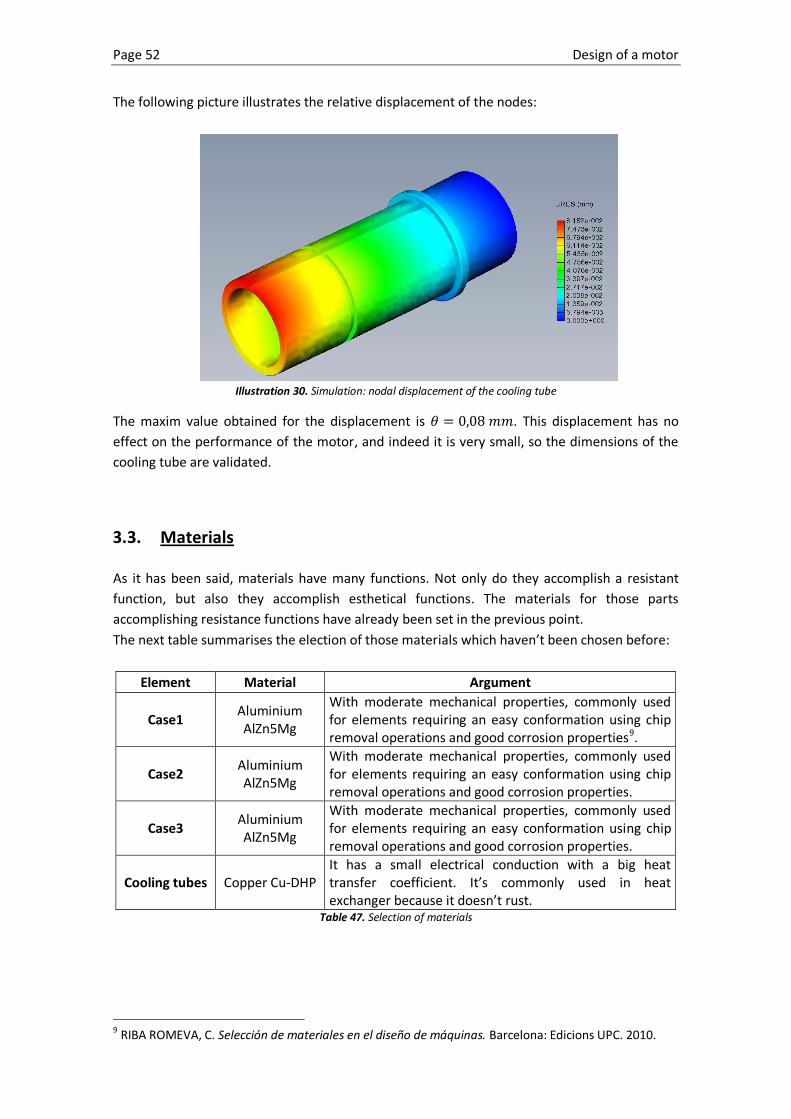
Page 52 Design of a motor
The following picture illustrates the relative displacement of the nodes:
Illustration 30. Simulation: nodal displacement of the cooling tube
The maxim value obtained for the displacement is . This displacement has no
effect on the performance of the motor, and indeed it is very small, so the dimensions of the
cooling tube are validated.
3.3. Materials
As it has been said, materials have many functions. Not only do they accomplish a resistant
function, but also they accomplish esthetical functions. The materials for those parts
accomplishing resistance functions have already been set in the previous point.
The next table summarises the election of those materials which haven’t been chosen before:
Element Material Argument
Case1 Aluminium AlZn5Mg
With moderate mechanical properties, commonly used for elements requiring an easy conformation using chip removal operations and good corrosion properties9.
Case2 Aluminium AlZn5Mg
With moderate mechanical properties, commonly used for elements requiring an easy conformation using chip removal operations and good corrosion properties.
Case3 Aluminium AlZn5Mg
With moderate mechanical properties, commonly used for elements requiring an easy conformation using chip removal operations and good corrosion properties.
Cooling tubes Copper Cu-DHP It has a small electrical conduction with a big heat transfer coefficient. It’s commonly used in heat exchanger because it doesn’t rust.
Table 47. Selection of materials
9 RIBA ROMEVA, C. Selección de materiales en el diseño de máquinas. Barcelona: Edicions UPC. 2010.

Design of a motor Page 53
These elements are chosen considering that a small amount of motors is going to be
manufactured. In case of manufacturing a large series of motors, the case 2 and the case 3,
which don’t bear loads and only accomplish isolating functions, would be made of polymers in
order to decrease the weight of the motor and the inside of the motor would still be isolated
from the possible environment attacks.
For the case 1, the material wouldn’t change depending on the amount of motors to be
manufactured. The case is provided with some threaded holes which allow the attachment to
the boat. These case have to be stiff enough to allow the motor be tightly screwed to the
mounting of the boat without the screw stopping biting.
If the series of motors was large enough, the cases 2 and 3 would be manufactured by
injection. The creation of this mould is only justified when the amount of elements to inject is
very big, so that the price of creating the expensive mould is shared between all the elements
manufactured and the mould is amortized.
The polymer chosen would be the polycarbonate. This thermoplastic is commonly used in case
for machines in order to take advantage of the following characteristics:
Easy to manufacture
Great mechanical characteristics in a range from -100ºC to 130ºC
Good structural stability facing rough weather
Self-extinguishing
It is especially important for them to have great mechanical characteristics in that range of
temperatures, as the case 3 has two holes through which the cooling tubes with the hot
cooling fluid go inside the motor.
3.4. Preparation of the prototype
This point covers the first stage of the prototype. This stage is thought to test the most basic
features of the motor (power, torque and speed) before spending more money on expensive
parts as the cooling serpentine and testing other features like the cooling.
The prototype has to satisfy the following requirements:
It has to be cheap
It has to be able to satisfy the main requirements and wishes explained before.
It has to have the same mechanic and electric characteristics than the motor.
As it has been said, the first stage of the prototype is thought to test the following features:
the power, the torque and the speed. For this reason, a very simple prototype will be made. In
order to accomplish the previous requirements, the prototype will have the following
characteristics:
The prototype will not be provided with a case.
The prototype will not be provided with a cooling system.

Page 54 Design of a motor
The attachment of the prototype has to be compatible with the attachment currently
existing on the test bench. The next picture has the main dimensions of the current
attachment on the test bench:
Illustration 31. Attachment plate test bench
The shaft has to be able to be coupled with the receptor of the test bench using the
coupling currently placed on the test bench. This is a standard coupling and its main
measurements are the following, being the hole of diameter 19 the one attached to
the receptor of the test bench:
Illustration 32. Coupling and size of the holes

Design of a motor Page 55
The following drawing is the result of the prototype accomplishing all the previous
requirements:
The prototype in the drawing accomplishes all the requirements previously set. The
stator (8), rotor (1), magnets (4) and coils (3) have exactly the same size, shape, and
consequently, properties than their respective in the original design.
The support added (12) provides an attachment compatible with the current plate on
the test bench.
Number Component
1 Rotor
2 Tube
3 Coil
4 Magnet
5 Shaft
6 Seeger ring
7 Rim
8 Stator
9 Bearing
10 Separator
11 Pin
12 Support
13 Hex Screw
14 Seeger ring
15 Hex flat socket

Page 56 Design of a motor
The diameter of the part of the shaft which is outside of the motor has been made
bigger in order to be coupled easily with a standard coupling already purchased.
All the elements not accomplishing any mechanical function have been omitted in the
prototype, so the result is a cheaper and simpler motor with the same characteristics than the
real design.
4. Conclusions
This text reports the process of the preliminary design to achieve a solution for a high
efficiency propelling system for the A boat competing in the Dong solar challenge.
After going through all the methodical resign process, now it’s time to evaluate how much the
solution developed satisfies the requirements and the wishes stated in the first points of this
report so that the motor can perform its main function, which is transmitting the
electromagnetic torque generated by the coils and the magnets of the motor to the propeller
of the A boat.
Just to remind, the requirements and the wishes stated at the beginning of the project are the
following:
High efficiency
Attachable
Easy to assemble
Low weight
Balance
The efficiency of the motor will be determined after the prototype is tested. At this point it can
be said that the efficiency of the global motor, concerning the mechanical part, has been
maximized by using the most efficient bearings available. The other possible losses of energy
produced by noise or vibrations due to a bad alignment have been minimized by setting a good
adjustment between the different parts that have to fit.
When talking about the attachment of the motor to the boat, the motor’s case has been
provided with an annulus of threaded holes which make it easy to attach face down to the
mounting existing in the boat. This way, the user only needs to screw 4 screws, without the
need of nuts and with only one tool.
When it comes to assembling the motor, an extra tool is needed in order to overcome the big
magnetic forces created by the permanent magnets towards the metallic parts that are willed
to be introduced inside the stator. Besides this, the assembly of the motor is easy, only
needing one hexagonal key for the screws and a wood hammer to place the bearings.
There are some parts of the motor that are made with heavy materials which cannot be
replaced. Some examples of it would be the permanent magnets, the coils or the laminas of
the rotor, or the cooling tube, which is made of a high heat transfer coefficient material such
as copper. The weight has been regarded giving small dimensions and light materials to
elements like the rim (aluminium) and the case (aluminium, polymer).

Design of a motor Page 57
The balance of the motor is a consequence of several conditions. The main reason is usually
because of a bad alignment of the shaft. This problem has been solved assigning the correct
tolerances to the bearings housing. Additionally, the stress calculations show that the shaft is
stiff enough to bear the loads applied on it so that not big variations on the shaft’s relative
position will appear, as the maximum displacement is of 0,2 mm when the maximum load is
applied.
5. Recommendations
As it has been previously said in this report, there is an increasing interest in the use of
technologies based on renewable energies and applications that can be given to them, such as
solar energy propelled vehicles. Despite this growing interest, the motor industry is not
offering a big choice of motors suitable for these applications (moderate power, low voltage).
There is a gap in the market for motors using low voltage, in a range of power from few
kilowatts to around ten kilowatts and designed according to the laws which involve personal
safety and use. This way they can be used to propel electric cars, bikes, boats and in general
any product needing a motor of the characteristics said above.
For this reasons, the next step would be an ambitious project of standardisation of the motors
satisfying these demands so that they can be available for this increasing demand.

Page 58 Design of a motor
Design of a motor Page 59
Bibliography [1] AYNETO, A.; MARIMON, F.; ROURE, F. Resistencia de Materiales. Barcelona: ETSEIB – CPDA.
1999.
[2] CHEVALIER, A. Dibujo industrial. Mexico: UTEHA, 1992.
[3] CLOS I COSTA, D. Quadern D3: Preprojectes. Barcelona: CPDA, 2010
[4] ELEMENTOS DE MÁQUINAS. Ajustes y Tolerancias. Uruguay, 2009.
[http://www.fing.edu.uy/iimpi/academica/grado/elemmaq/teorico/Ajustes&Tolerancias9-
4.pdf, 20th March 2012]
[5] EUROPEAN UNION. Policies and activities of the European Union. Leeuwarden, 2012.
[http://europa.eu/policies-activities/index_en.htm, 29th June 2012]
[6] FENOLLOSA, J. Càlcul de Màquines 2. Barcelona: ETSEIB – CPDA. 2008.
[7] JUANA SARDÓN, J. Física general. Volumen I. 2nd edition. Madrid: Pearson Educación S.A.
2007.
[8] RIBA ROMEVA, C. Selección de materiales en el diseño de máquinas. Barcelona: Edicions
UPC. 2010.
[9] SKF GROUP. Bearing’s catalogue. Leeuwarden, 2012.
[http://www.skf.com/portal/skf/home/products?maincatalogue=1&lang=en&newlink=1_1_1,
12th April 2012]
[10] VIVANCOS CALVET, J. Tecnologías de fabricación: teoría y problemas. Barcelona: ETSEIB –
CPDA, 2004.

Page 60 Design of a motor

Design of a motor Page 61
ANNEX A
Detail drawings

Page 62 Design of a motor

208 196
6 x 5 14 M6 - 6H 10
DETALLE Z ESCALA 2 : 1
R1 max
1 X 45°
DETALLE Y ESCALA 2 : 1
1 X 45°
1 X 45°
7 2
3
R1
YZ
A
Ra 0,8rectificado
0.01
A
158
18
4 H
7
72
52 H
8
46 m
in
R2
15 H6
20 150 G6
10
2
15 1 X 45°
Case 1
PESO:
A3
HOJA 1 DE 2ESCALA:1:2
N.º DE DIBUJO
TÍTULO:
REVISIÓNNO CAMBIE LA ESCALA
MATERIAL:
FECHAFIRMANOMBRE
REBARBAR Y ROMPER ARISTAS VIVAS
ACABADO:SI NO SE INDICA LO CONTRARIO:LAS COTAS SE EXPRESAN EN MMACABADO SUPERFICIAL:TOLERANCIAS: LINEAL: ANGULAR:
CALID.
FABR.
APROB.
VERIF.
DIBUJ.
2.1


Case 1
87
4 x 8.5 19.5M10 - 6H 12
PESO:
A3
HOJA 2 DE 2ESCALA:1:5
N.º DE DIBUJO
TÍTULO:
REVISIÓNNO CAMBIE LA ESCALA
MATERIAL:
FECHAFIRMANOMBRE
REBARBAR Y ROMPER ARISTAS VIVAS
ACABADO:SI NO SE INDICA LO CONTRARIO:LAS COTAS SE EXPRESAN EN MMACABADO SUPERFICIAL:TOLERANCIAS: LINEAL: ANGULAR:
CALID.
FABR.
APROB.
VERIF.
DIBUJ.
2.1


DIBUJ.
Case 2
PESO:
A3
HOJA 1 DE 1ESCALA:1:2
N.º DE DIBUJO
TÍTULO:
REVISIÓNNO CAMBIE LA ESCALA
MATERIAL:
FECHAFIRMANOMBRE
VERIF.
APROB.
VIVAS
ACABADO:ROMPER ARISTAS REBARBAR Y
FABR.
CALID.
ANGULAR:
SI NO SE INDICA LO CONTRARIO:LAS COTAS SE EXPRESAN EN MMACABADO SUPERFICIAL:TOLERANCIAS: LINEAL:
2.2
6 x
94,5 196 208
6.6 POR TODO
3.9 11 6 x 5 17
M6 - 6H 7.50,01 A
A0,01
A
A
109
H7
10
80
H7
DETALLE A ESCALA 2 : 1
0,5 X 45°
R0,5
0,5 X 45°
7,5


DETALLE Y ESCALA 5 : 1
0,5 X 45°
0,5 X 45°
R0,5
Y
Z
A0,01
B0,01
SECCIÓN A-A
A
0,01 A
0,01 A
B
X 5
8 M
5
109
h6
0,5 X 45
°
80 g
6
0,5 X 45°
0,5 X 45°0,5 X 45°
10
15 H6
20 26
0,5 X 45°
24 h
7
24
R0,5
DETALLE Z ESCALA 5 : 1
0,5 X 45°
DETALLE X ESCALA 5 : 1
R0,5 DETALLE W
ESCALA 2 : 1
0,5 X 45°
6 j6
R0,5
W
3.9 11
62 H6 94,5
48
6 x 6.6 POR TODO
3 x 10 A
A
DIBUJ.
Case 3
PESO:
A3
HOJA 1 DE 1ESCALA:1:1
N.º DE DIBUJO
TÍTULO:
REVISIÓNNO CAMBIE LA ESCALA
MATERIAL:
FECHAFIRMANOMBRE
VERIF.
APROB.
VIVAS
ACABADO:ROMPER ARISTAS REBARBAR Y
FABR.
CALID.
ANGULAR:
SI NO SE INDICA LO CONTRARIO:LAS COTAS SE EXPRESAN EN MMACABADO SUPERFICIAL:TOLERANCIAS: LINEAL:
2.3


DIBUJ.
Rim 1
PESO:
A3
HOJA 1 DE 1ESCALA:1:2
N.º DE DIBUJO
TÍTULO:
REVISIÓNNO CAMBIE LA ESCALA
MATERIAL:
FECHAFIRMANOMBRE
VERIF.
APROB.
VIVAS
ACABADO:ROMPER ARISTAS REBARBAR Y
FABR.
CALID.
ANGULAR:
SI NO SE INDICA LO CONTRARIO:LAS COTAS SE EXPRESAN EN MMACABADO SUPERFICIAL:TOLERANCIAS: LINEAL:
2.4
10.4 X 90°
80 33,5
4 M6
30°
6 x
181,8 g6
6 x 5.5 POR TODO
168,5
A
A
SECCIÓN A-A
0,01 A
A0,01A
B
5 H6
46
H6
24 H
6
10 h6
DETALLE B ESCALA 5 : 1
TorneadoRa 3,2
0,5 X 45°
0,5 X 45°0,5 X 45°
R0,5


0,01 A
rectificadoRa 0,8
A
0,4
0,01
A
Z
90
15 h6
100
H6
11
DETALLE Z ESCALA 2 : 1
0,5 X 45°
R0,6 max 0,5 X 45°
0,5 X 45°
DIBUJ.
Rim 2
PESO:
A3
HOJA 1 DE 1ESCALA:1:2
N.º DE DIBUJO
TÍTULO:
REVISIÓNNO CAMBIE LA ESCALA
MATERIAL:
FECHAFIRMANOMBRE
VERIF.
APROB.
VIVAS
ACABADO:ROMPER ARISTAS REBARBAR Y
FABR.
CALID.
ANGULAR:
SI NO SE INDICA LO CONTRARIO:LAS COTAS SE EXPRESAN EN MMACABADO SUPERFICIAL:TOLERANCIAS: LINEAL:
2.5
168,5 120
40°
10.4 X 90°6 x 5.5 POR TODO
181,800 g6


16
x 14,
7°
16 x 8°
168,5
R78,9
181,800
R79,4
6 x 4.200 14 M5 - 6H 0
DIBUJ.
Stator
PESO:
A3
HOJA 1 DE 1ESCALA:1:2
N.º DE DIBUJO
TÍTULO:
REVISIÓNNO CAMBIE LA ESCALA
MATERIAL:
FECHAFIRMANOMBRE
VERIF.
APROB.
VIVAS
ACABADO:ROMPER ARISTAS REBARBAR Y
FABR.
CALID.
ANGULAR:
SI NO SE INDICA LO CONTRARIO:LAS COTAS SE EXPRESAN EN MMACABADO SUPERFICIAL:TOLERANCIAS: LINEAL:
2.6
0,01 A
A
181,800 168,5
6 x 4.200 14 M5 - 6H 0
0,01 B
B 120 k6


37,5 MIN.
SECCIÓN A-A ESCALA 2 : 1
DETALLE Z ESCALA 5 : 1
R0,5
0,5 X 45°
R0,5
0,5 X 45°
DIBUJ.
Cooling tube 1
PESO:
A3
HOJA 1 DE 1ESCALA: 2:1
N.º DE DIBUJO
TÍTULO:
REVISIÓNNO CAMBIE LA ESCALA
MATERIAL:
FECHAFIRMANOMBRE
VERIF.
APROB.
VIVAS
ACABADO:ROMPER ARISTAS REBARBAR Y
FABR.
CALID.
ANGULAR:
SI NO SE INDICA LO CONTRARIO:LAS COTAS SE EXPRESAN EN MMACABADO SUPERFICIAL:TOLERANCIAS: LINEAL:
2.8
A
A
0,01
0,01
A
Z
0,5 X 45°
27 4
0,5 X 45°
86
40
40
3
40
36 3
32 H
6
46
0,5 X 45°
A
A


DIBUJ.
Cooling tube 2
PESO:
A3
HOJA 1 DE 1ESCALA:1:1
N.º DE DIBUJO
TÍTULO:
REVISIÓNNO CAMBIE LA ESCALA
MATERIAL:
FECHAFIRMANOMBRE
VERIF.
APROB.
VIVAS
ACABADO:ROMPER ARISTAS REBARBAR Y
FABR.
CALID.
ANGULAR:
SI NO SE INDICA LO CONTRARIO:LAS COTAS SE EXPRESAN EN MMACABADO SUPERFICIAL:TOLERANCIAS: LINEAL:
2.9
DETALLE X ESCALA 5 : 1
0,5 X 45°
R0,3 MAX.
Y
Z
ESCALA 1 : 1
0,3
rectificado
0,3Ra 0,8
SECCIÓN A-A
rectificadoRa 0,8
X
110
0,5 X 45°
20 24 H
8
13
24 H
8
0,5 X 45°
9
0,5 X 45°
R0,5
32
k5
15 h6
DETALLE Z ESCALA 5 : 1
0,5 X 45°
DETALLE Y ESCALA 5 : 1
0,5 X 45°
R0,3 MAX.
3 x 10
62 js5
48
6 H7 A
A


2
DIBUJ.
Shaft
PESO:
A3
HOJA 1 DE 1ESCALA:1:1
N.º DE DIBUJO
TÍTULO:
REVISIÓNNO CAMBIE LA ESCALA
MATERIAL:
FECHAFIRMANOMBRE
VERIF.
APROB.
VIVAS
ACABADO:ROMPER ARISTAS REBARBAR Y
FABR.
CALID.
ANGULAR:
SI NO SE INDICA LO CONTRARIO:LAS COTAS SE EXPRESAN EN MMACABADO SUPERFICIAL:TOLERANCIAS: LINEAL:
2.12
DETALLE Y ESCALA 5 : 1
R1 max
0,5 X 45°
DETALLE X ESCALA 5 : 1
0,5 X 45°
R1 max
DETALLE W ESCALA 5 : 1
R0,
5
DETALLE V ESCALA 5 : 1
1 X 45°1 X 45°
5
DETALLE U ESCALA 5 : 1
R0,5
DETALLE T ESCALA 5 : 1
1 X 45°
R0,3 max
DETALLE S ESCALA 5 : 1
1 6
1 X 15°
0,5
DETALLE Z ESCALA 5 : 1
1 X 45°
46 js5
33,500
6 x 4 H7 4 N9
S
A
U
T
V
rectificadoRa 0,40,3Y
W
X
A
0,3
0,01
Ra 0,4rectificado
0,01 A
0,01 A
0,01 A
0,01
A
Z
11 15 57,5
12
20 k
6
24 js
5
M6
12 7,5
16
12
k6
5 js5
10
-0 0,1
122


Design of a motor Page 72
ANNEX B
Assembly drawings


22 1 Seeger rings for shafts DIN 471 A 12 Seeger
21 1 Seeger rings for shafts DIN 471 A 40 Seeger
20 1 Seeger rings for shafts DIN 472 J 52 Seeger
19 12 Socket flat head screws M6 ISO 10642 8.818 6 Stainless dowel pin DIN 7 4m6x10 -17 12 Socket head cap screws M6 ISO 4762 8.816 1 Separator 2.11
15 1 Single row deep groove ball bearings 6304 SKF
14 1 Singlr row deep groove ball bearings 61816 SKF
13 1 Case 1 2.112 1 Case 2 2.211 1 Rim 2 2.510 1 Shaft 2.129 1 Rim 1 2.48 1 Stator 2.67 1 Case 3 2.3
6 2 Single row deep groove ball bearings 61901 SKF
5 16 Magnet 2.104 1 Cooling tube 2 2.93 1 Cooling tube 1 2.82 12 Coil1 1 Rotor 2.7
Number Quantity Name Ref Observations
VERIF. Element list
PESO:
A4
HOJA 1 DE 1ESCALA:1:1
N.º DE DIBUJO
TÍTULO:
REVISIÓNNO CAMBIE LA ESCALA
MATERIAL:
FECHAFIRMANOMBRE
APROB.
FABR.
VIVAS
ACABADO:ROMPER ARISTAS REBARBAR Y
CALID.
ANGULAR:
SI NO SE INDICA LO CONTRARIO:LAS COTAS SE EXPRESAN EN MMACABADO SUPERFICIAL:TOLERANCIAS: LINEAL:
DIBUJ.


M8R12N.º DE DIBUJO
PESO:
A3
HOJA 1 DE 1ESCALA:1:5
MATERIAL:
C
C
21
22
ESCALA 1 : 1SECCIÓN C-C
10
13
15
18
12
7
4
3
14
6
6
8 5 1 2
9
11
17
17
17
17
20


M8R12
SECCIÓN A-A ESCALA 1 : 2
A
A
PESO:
A3
HOJA 1 DE 1ESCALA:1:5
N.º DE DIBUJO
TÍTULO:
REVISIÓNNO CAMBIE LA ESCALA
MATERIAL:
FECHAFIRMANOMBRE
REBARBAR Y ROMPER ARISTAS VIVAS
ACABADO:SI NO SE INDICA LO CONTRARIO:LAS COTAS SE EXPRESAN EN MMACABADO SUPERFICIAL:TOLERANCIAS: LINEAL: ANGULAR:
CALID.
FABR.
APROB.
VERIF.
DIBUJ.