Design a Robust RST Controller for Stabilization of a Tri ... · Design a Robust RST Controller for...
12
PJETS Volume 5, No 1, 2015 Pak. j. eng. technol. sci. Volume 5, No 1, 2015, 60-71 ISSN: 2222-9930 print ISSN: 2224-2333 online 60 Design a Robust RST Controller for Stabilization of a Tri-Copter UAV 1. Zain Anwar Ali,2.Dao Bo Wang, 3.Muhammad Aamir 1&2.College of Automation Engineering Department, Nanjing University of Aeronautics & Astronautics, Nanjing, China 3. Sir Syed University of Engineering & Technology Karachi, Pakistan. E-mail: [email protected], ABSTRACT Research on the tri-rotor aerial robot is due to extra efficiency over other UAV’s regarding stability, power and size requirements. We require a controller to achieve 6-Degree Of Freedom (DOF), for such purpose, we propose the RST controller to operate our tri-copter model. A MIMO model of a tri-copter aerial robot is challenged in the area of control engineering. Ninestates of output control dynamics are treated individually. We designed dynamic controllers to stabilize the parameters of an UAV. The resulting system control algorithm is capable of stabilizing our UAV to perform numerous operations autonomously. The estimation and simulation implemented inMATLAB, Simulink to verify the results. All real flight test results are presented to prove the success of the planned control structure. Key-Words: Unmanned Vehicle, Tri-copter Controlling, Dynamically Controlling, RST (Regulation, Pole Placement & Tracking) 1. INTRODUCTION The UAVs (Unmanned Aerial Vehicles) is the flying vehicles
Transcript of Design a Robust RST Controller for Stabilization of a Tri ... · Design a Robust RST Controller for...
PJETS Volume 5, No 1, 2015
Pak. j. eng. technol. sci.Volume 5, No 1, 2015, 60-71ISSN: 2222-9930 printISSN: 2224-2333 online
60
Design a Robust RST Controller for Stabilizationof a Tri-Copter UAV
1. Zain Anwar Ali,2.Dao Bo Wang, 3.Muhammad Aamir
1&2.College of Automation Engineering Department, NanjingUniversity of Aeronautics & Astronautics, Nanjing, China
3. Sir Syed University of Engineering & Technology Karachi,Pakistan.
E-mail: [email protected],
ABSTRACTResearch on the tri-rotor aerial robot is due to extra efficiency
over other UAV’s regarding stability, power and sizerequirements. We require a controller to achieve 6-DegreeOf Freedom (DOF), for such purpose, we propose the RSTcontroller to operate our tri-copter model. A MIMO modelof a tri-copter aerial robot is challenged in the area of controlengineering. Ninestates of output control dynamics are treatedindividually. We designed dynamic controllers to stabilize theparameters of an UAV. The resulting system control algorithmis capable of stabilizing our UAV to perform numerousoperations autonomously. The estimation and simulationimplemented inMATLAB, Simulink to verify the results. Allreal flight test results are presented to prove the success ofthe planned control structure.
Key-Words: Unmanned Vehicle, Tri-copter Controlling,Dynamically Controlling, RST (Regulation, Pole Placement& Tracking)
1. INTRODUCTION
The UAVs (Unmanned Aerial Vehicles) is the flying vehicles
PJETS Volume 5, No 1, 2015
without pilot, which have seen rapid growth in militarysurveillance and civilian rescue operations during the lastdecades.UAVs have been developed in a wide variety ofshapes, sizes, configurations, and characteristics. Thedevelopment of UAVs, began in the early 1900’s, and thetechnology in its early stages was used by the military due inWorld War I and expanded by World War II [6]. For thedevelopment of the UAVS it is necessary to have avariety of knowledge, including aeronautics, autonomouscontrol, and signal processing and different types of sensors.There are numerous necessities for UAVs used in such areas,Such as the UAV must be small, sized quick movements sothat it could avoid a sudden collision, have vertical takeoff andlanding ability, and also in sudden directional turns.To fulfill all the above necessities, a multi-rotor thrust UAV isthe best solution for this [2]. The growing recognition of thepotential of using UAVs for search and rescue applications issupported by an increasing number of works in the areas ofimage recognition for victim detection, path planning and taskallocation [3-4].
Different types of multi-rotor have been developed include suchas Bi-copter, Tri-copter, Quad-copter as well as hex-copterand conventional rotor craft and helicopters. In this researchour main concern is Tri-rotor Vehicle and also called as Tri-copter. Tri-copter has three motor systems and is less-expensiveand has more flexibility.One clear advantage of a Tri-rotor over a quad-rotor is thatIt requires one less motor, leading to a reduction in weight,Volume and energy consumption [5]. As compared to quad-rotors have a longer flight time due to a reduction in the numberof motors. Smaller in size and low cost makes it ideal fordeployment in various military and civil research missions. In
61
PJETS Volume 5, No 1, 2015
general, tilt rotor configuration is used to control the forces onthe horizontal and only one tail rotor has an ability to controlthe yaw moment. Tri-rotor vehicles Dynamics are extremelycoupled and nonlinear, the development of controller designfor such vehicles is the key problem for successful flight ando p e r a t i o n s . M a n y r e s e a r c h e r s h a v e b e e naddressing control design problems for VTOLs in order toaccomplish a higher accuracy and robustness given in thepresence of model uncertainties and disturbances. Numeroustypes of control techniques have been developed such as thediscrete PID controller, a linear, quadratic regulator (LQR)method to control.Robust adaptive and back stepping control methods wereproposed and validated experimentally on a quad rotor.Although the control methods used in different manuscript andwork effectively. But the structure of controller parametersadjustment is complicated. So adaptability and robustness ofthe controllers are imperfect. Therefore, emerging a controllerfor the tri-rotor with modest structure, simple way to tuningparameters and decent adaptability is important. For stabilizingthe UAV in this research, we use the RST robust controller.The actuators of tri-copter are controlled by the servo motor.The major forces reacts on the vehicle are produced by thepropeller that can handle the controlling of yaw, pitch, roll andaltitude of the aerial vehicle. The Euler angles of elevation andvelocities have been controlled by a Robust RST controllermethod. The division of this paper which is divided into 5sections. In section 2 equations of motions of the tri-coptervehicle is defined along with its dynamics. In the section 3 &4, the Engine model and the designing a control strategy tocontrol the parameters is defined. Moreover, the simulationand results are shown in section 5. 2. EQUATION OF MOTIONS& DYNAMICS OF TRI-ROTOR VEHICLE.
62
PJETS Volume 5, No 1, 2015
To develop the model of the tri-copter which is derived by using Newton-Euler Formulation. The vehicle is described using a right hand, the generalizedthe earth coordinatethe system of axes and the right hand body frame. Positive 푥-axis points towards the front rotors (rotors 1 and 2), positive 푦-axis points towards the right (rotor 2), and positive 푧-axis is directed downwards. The Positive sense of three angular variables Roll (휙), Pitch (휃), and Yaw (휓) is decided by a right-handed rotation about positive 푥, 푦, and 푧axes, respectively [1]. The tilt angle 휇is measured by 푦-푧coordinate axis. The dynamic modeling suggested of the triple tilting rotor. The UAV is introduced based on Newton-Euler mathematical formulation, which has six degrees of freedom (DOF) and four inputs: three speeds of watercraft and one tilt angle. Following the conventional helicopter control commands, tri-rotor UAVs have similar commands, which are collective, lateral, longitudinal, and yaw or pedal [2]. They are indicated as 훿 col, 훿lat (Roll control), 훿l on (Pitch control), and 훿Ped (Yaw control). Since two front rotors operateat different speeds, they generate Roll (휙) control, for example, when the speed of rotor 1 is up and that of the rotor 2 down, and make the UAV toward the right and vice versa. The Pitch (휃) control is created as the third tail rotor changes velocity. The achievement Yaw (휓) control occurs by varying the tilt angle 휇. The nonlinear equations of motion of conventional UAVs, which have 6 DOFs, are also used for tri-rotor UAVs. The designed model is free to rotate and translate of3Dspace [2]. 63
PJETS Volume 5, No 1, 2015
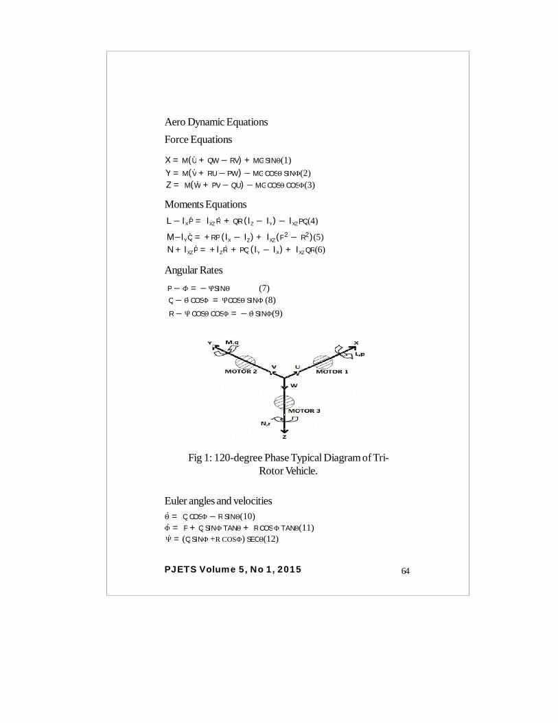
Aero Dynamic EquationsForce Equations
X = M(U + QW− RV) + MG SINΘ(1) Y = M(V + RU− PW) − MG COSΘ SINΦ(2) Z = M(W + PV− QU) − MG COSΘ COSΦ(3)
Moments EquationsL− IX P = IXZ R + QR (IZ − IY) − IXZ PQ(4)
M−IY Q = +RP (IX − IZ ) + IXZ (P2 − R2)(5) N + IXZ P = +IZR + PQ (IY − IX) + IXZ QR(6)
Angular RatesP − Φ = − ΨSINΘ (7) Q − Θ COSΦ = ΨCOSΘ SINΦ (8) R − Ψ COSΘ COSΦ = − Θ SINΦ(9)
Fig 1: 120-degree Phase Typical Diagram of Tri-Rotor Vehicle.
Euler angles and velocitiesΘ = Q COSΦ− R SINΘ(10) Φ = P + Q SINΦ TANΘ + R COSΦ TANΘ(11) Ψ = (Q SINΦ +R COSΦ) SECΘ(12)
64
PJETS Volume 5, No 1, 2015
3.THE MAIN ENGINE MODEL OF TRI-COPTER
A permanent DC servo motor is a very useful factor in most ofthe real time control systems in modern UAVS. Where themotor input signal relates to the armature voltage VA (t) dependsupon the time, and output signal relates to the angular positionθ (t), where Ra is the resistance and La is the inductance of thearmature winding in the motor. The angular rotation responsibleto generate the back EMF (Vb) and inertia or load of the motor(J) and where a damping factor is B.The equations of the electrical system are as follows.
Va(t) = Raia(t) + La dia(t)
dt+ Vb (t) (13)
Equation (13) Along with equation (14)
Vb (t) = Kbdθ(t)
dt (14)
Va(t) = Ra ia(t) + La dia(t)
dt+ Kb
dθ(t)dt
(15)
Where is the motor back EMF constant. The equation forthe mechanical side system is defined as below.
d2θ(t)dt2 + B
dθ(t)dt
= Tapp (t) (16)
Tapp (t) = KTia (t) (17)
Jd2θ(t)
dt2 + Bdθ(t)
dt= KTia (t) (18)
Where is the applied torque, and is the torqueconstant that relates the torque to the armature current.
65
PJETS Volume 5, No 1, 2015
Some pros of the servo motor are as follows.
The speed of operation of a servo motor isdefined as the required time for the shaft toreach a specified position. Common servoshave operating speeds in the range of 0.05 to0.2 s/60 degree
Typical values of torques of servo motors arein the range of 0.5 to 10 kg/cm.
This characteristic is important in themechanical design of projects. Typical RCservo motors have a weight range between 15and 200g [7].
4. DESIGNING A CONTROL STRATEGY TO CONTROLTHE PARAMETERS.
We have used an RST controller with the zero cancellation togain an optimal-desired response from an actual response.The actual response is given in the equation (a).
Gθ ,∅,φ = Bm (q)Am (q)
(19)
Translational and Rotational movement ControlImplementation of the RST controller for achieving the desiredresponse is a key feature of our algorithm through which wecan control the dynamics of the tri-copter. Poles of our actualsystem are 3 and zeros are 2, through which we can identifythe order of the controls. The equation (20) is used to identifythe order of the controller,Ac = 2*deg A – 1 (20)This shows that Controller must be 2nd ordered. The Degreeof RST must be the 2nd order. We used a zero cancellationapproach to achieve our desired response. So the degree ofAo is found to be zero.
66
PJETS Volume 5, No 1, 2015
4" R- = for pole zero cancellation,
degAo = degA - deg - 1
So taking,Ao = 1
The Diophantine equation is stated in the equation (21),
Ao*Am = A R− + B−(S)(21)
∴S = s0q2 + s1q + s2(22)
T = Bm (Z)B−
(23)
U(t) = TR
Uc(t) − SR
y(t)(24)
Equation (24) represent the control law for controlling thedesired parameters i.e., Yaw Pitch and roll.
5. SIMULATION RESULTSHere we simulate the control algorithm for the tri-copter modelusing an RST controller by applying robust technique. Weassume all the initial conditions are zero and the desired systemresponse within the stable limits.
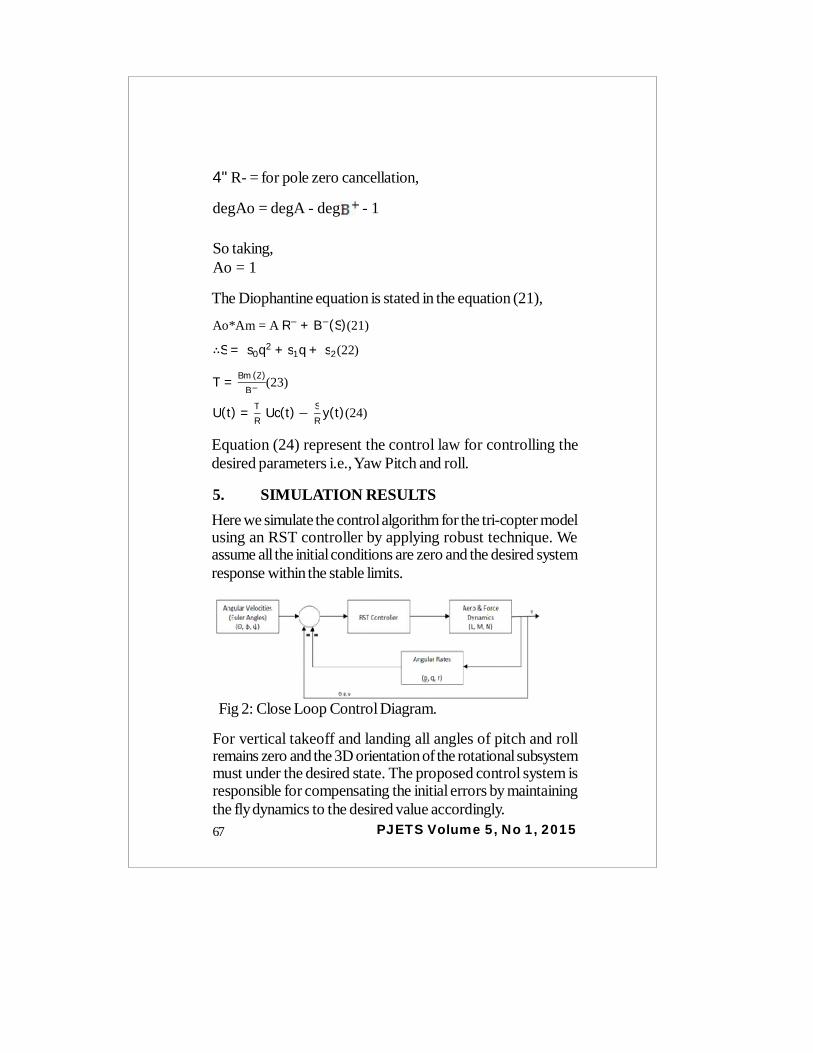
Fig 2: Close Loop Control Diagram.
For vertical takeoff and landing all angles of pitch and rollremains zero and the 3D orientation of the rotational subsystemmust under the desired state. The proposed control system isresponsible for compensating the initial errors by maintainingthe fly dynamics to the desired value accordingly.67
PJETS Volume 5, No 1, 2015
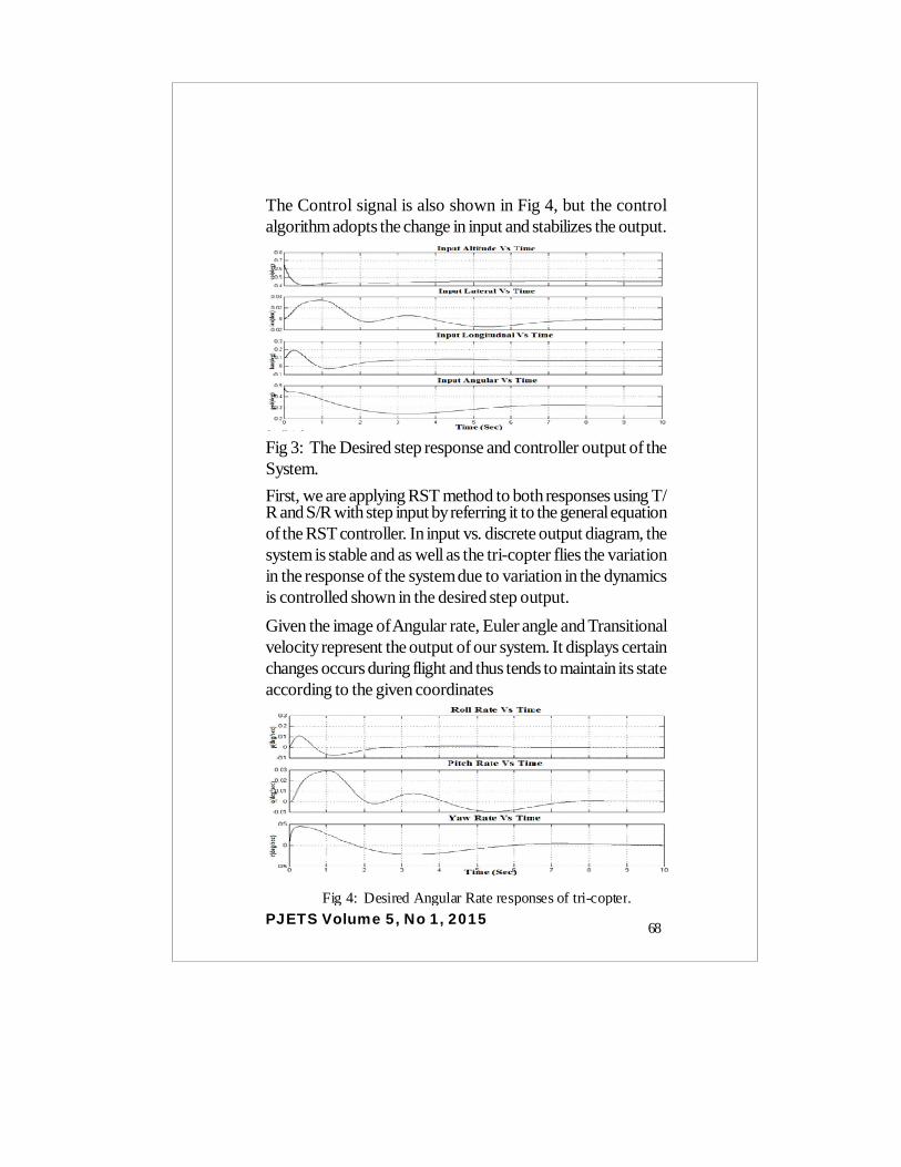
The Control signal is also shown in Fig 4, but the controlalgorithm adopts the change in input and stabilizes the output.
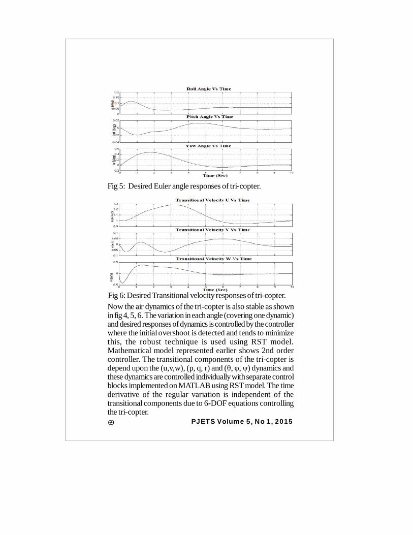
Fig 3: The Desired step response and controller output of theSystem.First, we are applying RST method to both responses using T/R and S/R with step input by referring it to the general equationof the RST controller. In input vs. discrete output diagram, thesystem is stable and as well as the tri-copter flies the variationin the response of the system due to variation in the dynamicsis controlled shown in the desired step output.Given the image of Angular rate, Euler angle and Transitionalvelocity represent the output of our system. It displays certainchanges occurs during flight and thus tends to maintain its stateaccording to the given coordinates
Fig 4: Desired Angular Rate responses of tri-copter.
68
PJETS Volume 5, No 1, 2015
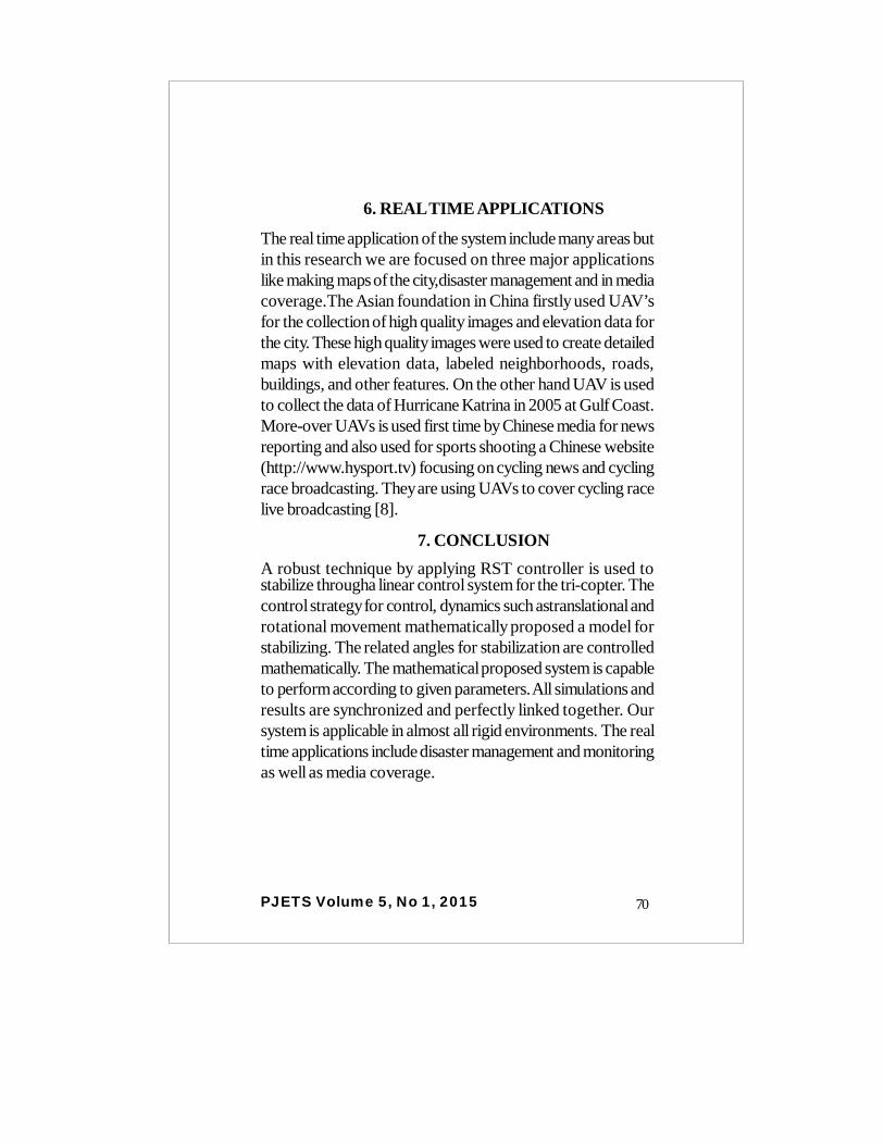
Fig 5: Desired Euler angle responses of tri-copter.
Fig 6: Desired Transitional velocity responses of tri-copter.Now the air dynamics of the tri-copter is also stable as shownin fig 4, 5, 6. The variation in each angle (covering one dynamic)and desired responses of dynamics is controlled by the controllerwhere the initial overshoot is detected and tends to minimizethis, the robust technique is used using RST model.Mathematical model represented earlier shows 2nd ordercontroller. The transitional components of the tri-copter isdepend upon the (u,v,w), (p, q, r) and (θ, φ, ψ) dynamics andthese dynamics are controlled individually with separate controlblocks implemented on MATLAB using RST model. The timederivative of the regular variation is independent of thetransitional components due to 6-DOF equations controllingthe tri-copter.69
PJETS Volume 5, No 1, 2015
6. REAL TIME APPLICATIONS
The real time application of the system include many areas butin this research we are focused on three major applicationslike making maps of the city,disaster management and in mediacoverage.The Asian foundation in China firstly used UAV’sfor the collection of high quality images and elevation data forthe city. These high quality images were used to create detailedmaps with elevation data, labeled neighborhoods, roads,buildings, and other features. On the other hand UAV is usedto collect the data of Hurricane Katrina in 2005 at Gulf Coast.More-over UAVs is used first time by Chinese media for newsreporting and also used for sports shooting a Chinese website(http://www.hysport.tv) focusing on cycling news and cyclingrace broadcasting. They are using UAVs to cover cycling racelive broadcasting [8].
7. CONCLUSIONA robust technique by applying RST controller is used tostabilize througha linear control system for the tri-copter. Thecontrol strategy for control, dynamics such astranslational androtational movement mathematically proposed a model forstabilizing. The related angles for stabilization are controlledmathematically. The mathematical proposed system is capableto perform according to given parameters. All simulations andresults are synchronized and perfectly linked together. Oursystem is applicable in almost all rigid environments. The realtime applications include disaster management and monitoringas well as media coverage.
70
PJETS Volume 5, No 1, 2015
References
[1] Kulhare, Anil, Arindam Bhanja Chowdhury, and GauravRaina. “A back-stepping control strategy for the Tri-rotor UAV”,2012 24th Chinese Control and Decision Conference (CCDC),2012.[2] Yoo, Dong-Wan, Hyon-Dong Oh, Dae-Yeon Won, andMin-Jea Tahk. “Dynamic modeling and control system designfor Tri-Rotor UAV”, 2010 3rd International Symposium onSystems and Control in Aeronautics and Astronautics, 2010.[3] P. Doherty and P. Rudol, “A uav search and rescue scenariowith human body detection and geolocalization,” in In 20th JointConference onArtiûcial Intelligence (AI07), 2007.[4] M. Goodrich, B. Morse, D. Gerhardt, J. Cooper, M.Quigley, J. Adams, and C. Humphrey, “Supporting wildernesssearch and rescue using acamera-equipped mini uav: Researcharticles,” J. Field Robot., vol. 25,no. 1-2, pp. 89–110, 2008.[5]A Back-stepping Control Strategy for theTri-rotor UAV, Anil Kulhare, Arindam Bhanja Chowdhury andGaurav Raina, 2012, 24th Chinese Control and DecisionConference (CCDC).[6] Yanbo Huang1, Steven J. Thomson1, Development andprospect of unmanned aerial vehicle technologies for agriculturalproduction management.
[7]www.robotiksistem.com/servo_motor_types_properties.html.[8] Civil Aviation Administration of China, administration of civildrones’ air-traffic,http://www.caac.gov.cn/dev/kgbgs/ZCFB/200907/P020090713547175111934.pdf
71

![Robust stabilization of multivariable systems ...george1/[A.24] Robust stabilization of...Robust stabilization of multivariable systems: Directionality and Super-optimisation ... (lcf](https://static.fdocuments.us/doc/165x107/5afd31637f8b9a68498c847a/robust-stabilization-of-multivariable-systems-george1a24-robust-stabilization.jpg)


![QUASI-OPTIMAL ROBUST STABILIZATION OF CONTROL SYSTEMS · derived for such control systems (see, for instance, [8, 29] and the references therein). The robust asymptotic stabilization](https://static.fdocuments.us/doc/165x107/5f6545ad12a04627aa25eb44/quasi-optimal-robust-stabilization-of-control-systems-derived-for-such-control-systems.jpg)