Cryogenic helium circulation pumps for forced flow cooling · Cryogenic helium circulation pumps...
20
Cryogenic helium circulation pumps for forced flow cooling | H. Neumann, G. Zahn | March 2009 www.kit.edu Cryogenic helium circulation pumps for forced flow cooling Institute for Technical Physics Holger Neumann, Gernot Zahn
Transcript of Cryogenic helium circulation pumps for forced flow cooling · Cryogenic helium circulation pumps...
Cryogenic helium circulation pumps for forced flow cooling | H. Neumann, G. Zahn | March 2009 www.kit.edu
Cryogenic helium circulation pumps for forced flow coolingInstitute for Technical Physics
Holger Neumann, Gernot Zahn
Cryogenic helium circulation pumps for forced flow cooling | H. Neumann, G. Zahn | March 2009
KIT – die Kooperation von Forschungszentrum Karlsruhe GmbH und Universität Karlsruhe (TH)
2
Content
Advantages of Helium circulation pumps in forced flow cooling loops
History and development of Helium pumps
Different types of Pumps pistoncentrifugalthermo mechanical
Requirements for ITER
Existing Helium pumps in the research institutes of Europe and Japan
Development for ITER and test option for the pumps
Conclusions
Cryogenic helium circulation pumps for forced flow cooling | H. Neumann, G. Zahn | March 2009
KIT – die Kooperation von Forschungszentrum Karlsruhe GmbH und Universität Karlsruhe (TH)
3
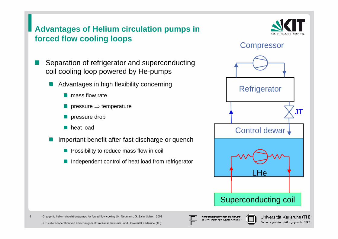
Advantages of Helium circulation pumps in forced flow cooling loops
Separation of refrigerator and superconducting coil cooling loop powered by He-pumps
Advantages in high flexibility concerning
mass flow rate
pressure ⇒ temperature
pressure drop
heat load
Important benefit after fast discharge or quench
Possibility to reduce mass flow in coil
Independent control of heat load from refrigerator
Refrigerator
Superconducting coil
Control dewar
Compressor
LHe
JT
Cryogenic helium circulation pumps for forced flow cooling | H. Neumann, G. Zahn | March 2009
KIT – die Kooperation von Forschungszentrum Karlsruhe GmbH und Universität Karlsruhe (TH)
4
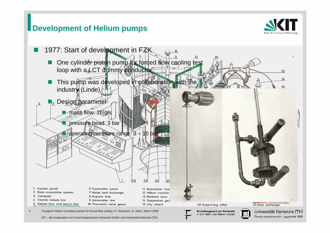
Development of Helium pumps
1977: Start of development in FZK
One cylinder piston pump for forced flow cooling test loop with a LCT dummy conductor
This pump was developed in collaboration with the industry (Linde)
Design parameter
mass flow: 20 g/s
pressure head: 3 bar
operating pressure range: 3 – 10 bar
Cryogenic helium circulation pumps for forced flow cooling | H. Neumann, G. Zahn | March 2009
KIT – die Kooperation von Forschungszentrum Karlsruhe GmbH und Universität Karlsruhe (TH)
5
Development of a three cylinder piston Helium pump
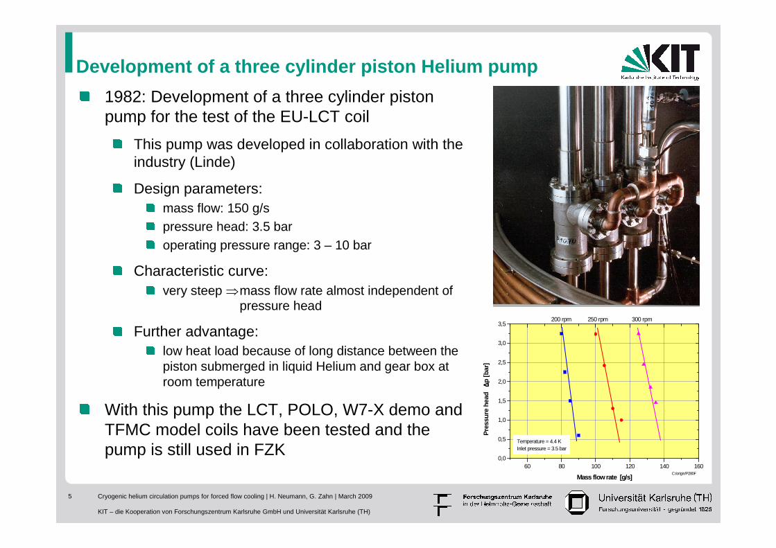
1982: Development of a three cylinder piston pump for the test of the EU-LCT coil
This pump was developed in collaboration with the industry (Linde)
Design parameters:mass flow: 150 g/spressure head: 3.5 baroperating pressure range: 3 – 10 bar
Characteristic curve:very steep ⇒mass flow rate almost independent of
pressure head
Further advantage:low heat load because of long distance between the piston submerged in liquid Helium and gear box at room temperature
With this pump the LCT, POLO, W7-X demo and TFMC model coils have been tested and the pump is still used in FZK
60 80 100 120 140 1600,0
0,5
1,0
1,5
2,0
2,5
3,0
3,5
Temperature = 4.4 KInlet pressure = 3.5 bar
C:/origin/P280F
200 rpm 250 rpm 300 rpm
Pre
ssur
e he
ad
∆∆ ∆∆p [b
ar]
Mass flow rate [g/s]
Cryogenic helium circulation pumps for forced flow cooling | H. Neumann, G. Zahn | March 2009
KIT – die Kooperation von Forschungszentrum Karlsruhe GmbH und Universität Karlsruhe (TH)
6
Development of a Helium centrifugal pump
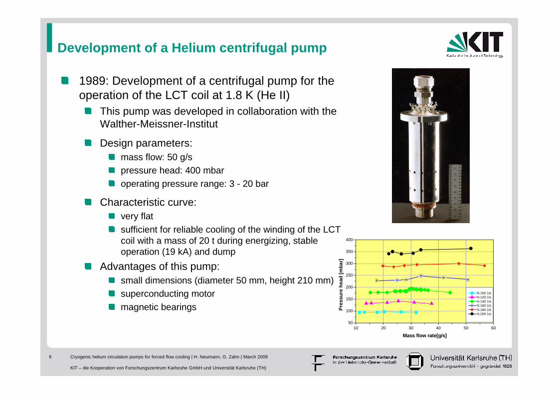
1989: Development of a centrifugal pump for the operation of the LCT coil at 1.8 K (He II)
This pump was developed in collaboration with the Walther-Meissner-Institut
Design parameters:mass flow: 50 g/spressure head: 400 mbaroperating pressure range: 3 - 20 bar
Characteristic curve:very flat sufficient for reliable cooling of the winding of the LCT coil with a mass of 20 t during energizing, stable operation (19 kA) and dump
Advantages of this pump:small dimensions (diameter 50 mm, height 210 mm)superconducting motormagnetic bearings
10 20 30 40 50 6050
100
150
200
250
300
350
400
N.100 1/s N.120 1/s N.140 1/s N.160 1/s N.180 1/s N.200 1/s
Pre
ssu
re h
ead
[m
bar
]Mass flow rate[g/s]
Cryogenic helium circulation pumps for forced flow cooling | H. Neumann, G. Zahn | March 2009
KIT – die Kooperation von Forschungszentrum Karlsruhe GmbH und Universität Karlsruhe (TH)
7
Development of a thermo mechanical pump
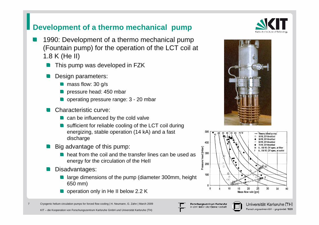
1990: Development of a thermo mechanical pump (Fountain pump) for the operation of the LCT coil at 1.8 K (He II)
This pump was developed in FZK
Design parameters:mass flow: 30 g/spressure head: 450 mbaroperating pressure range: 3 - 20 mbar
Characteristic curve:can be influenced by the cold valve sufficient for reliable cooling of the LCT coil during energizing, stable operation (14 kA) and a fast discharge
Big advantage of this pump:heat from the coil and the transfer lines can be used as energy for the circulation of the HeII
Disadvantages:large dimensions of the pump (diameter 300mm, height 650 mm)operation only in He II below 2.2 K
Cryogenic helium circulation pumps for forced flow cooling | H. Neumann, G. Zahn | March 2009
KIT – die Kooperation von Forschungszentrum Karlsruhe GmbH und Universität Karlsruhe (TH)
8
Development of a larger centrifugal pump
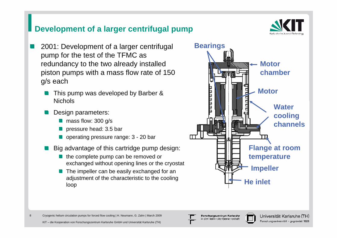
Motor chamber
Motor
Watercoolingchannels
Bearings
He inlet
Impeller
Flange at room temperature
2001: Development of a larger centrifugal pump for the test of the TFMC as redundancy to the two already installed piston pumps with a mass flow rate of 150 g/s each
This pump was developed by Barber & Nichols
Design parameters:mass flow: 300 g/spressure head: 3.5 baroperating pressure range: 3 - 20 bar
Big advantage of this cartridge pump design: the complete pump can be removed or exchanged without opening lines or the cryostatThe impeller can be easily exchanged for an adjustment of the characteristic to the cooling loop
Cryogenic helium circulation pumps for forced flow cooling | H. Neumann, G. Zahn | March 2009
KIT – die Kooperation von Forschungszentrum Karlsruhe GmbH und Universität Karlsruhe (TH)
9
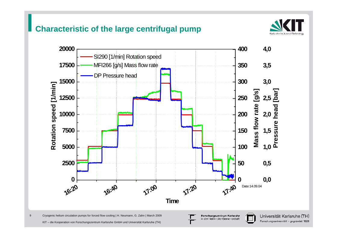
Characteristic of the large centrifugal pump
16:2016:40
17:0017:20
17:400
2500
5000
7500
10000
12500
15000
17500
20000
0
50
100
150
200
250
300
350
400
0,0
0,5
1,0
1,5
2,0
2,5
3,0
3,5
4,0R
ota
tio
n s
pee
d [
1/m
in]
Time
Date:14.09.04
SI290 [1/min] Rotation speed MFI266 [g/s] Mass flow rate
Mas
s fl
ow
rat
e [g
/s]
DP Pressure head
Pre
ssu
re h
ead
[b
ar]
Cryogenic helium circulation pumps for forced flow cooling | H. Neumann, G. Zahn | March 2009
KIT – die Kooperation von Forschungszentrum Karlsruhe GmbH und Universität Karlsruhe (TH)
10
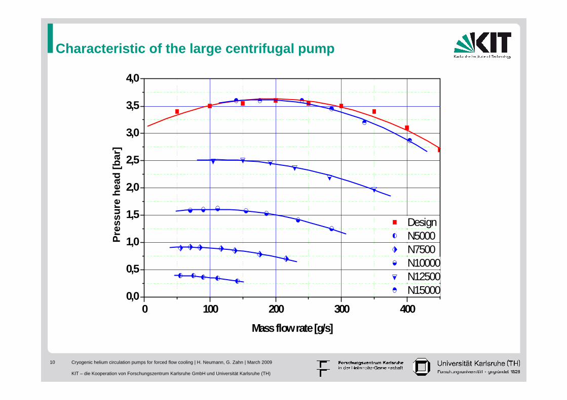
Characteristic of the large centrifugal pump
0 100 200 300 4000,0
0,5
1,0
1,5
2,0
2,5
3,0
3,5
4,0
Design N5000 N7500 N10000 N12500 N15000
Pre
ssu
re h
ead
[b
ar]
Mass flow rate [g/s]
Cryogenic helium circulation pumps for forced flow cooling | H. Neumann, G. Zahn | March 2009
KIT – die Kooperation von Forschungszentrum Karlsruhe GmbH und Universität Karlsruhe (TH)
11
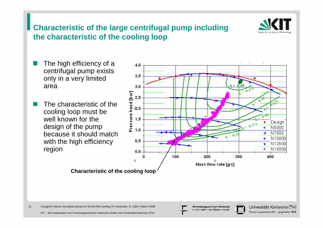
Characteristic of the large centrifugal pump including the characteristic of the cooling loop
The high efficiency of a centrifugal pump exists only in a very limited area
The characteristic of the cooling loop must be well known for the design of the pump because it should match with the high efficiency region
Characteristic of the cooling loop
Cryogenic helium circulation pumps for forced flow cooling | H. Neumann, G. Zahn | March 2009
KIT – die Kooperation von Forschungszentrum Karlsruhe GmbH und Universität Karlsruhe (TH)
12
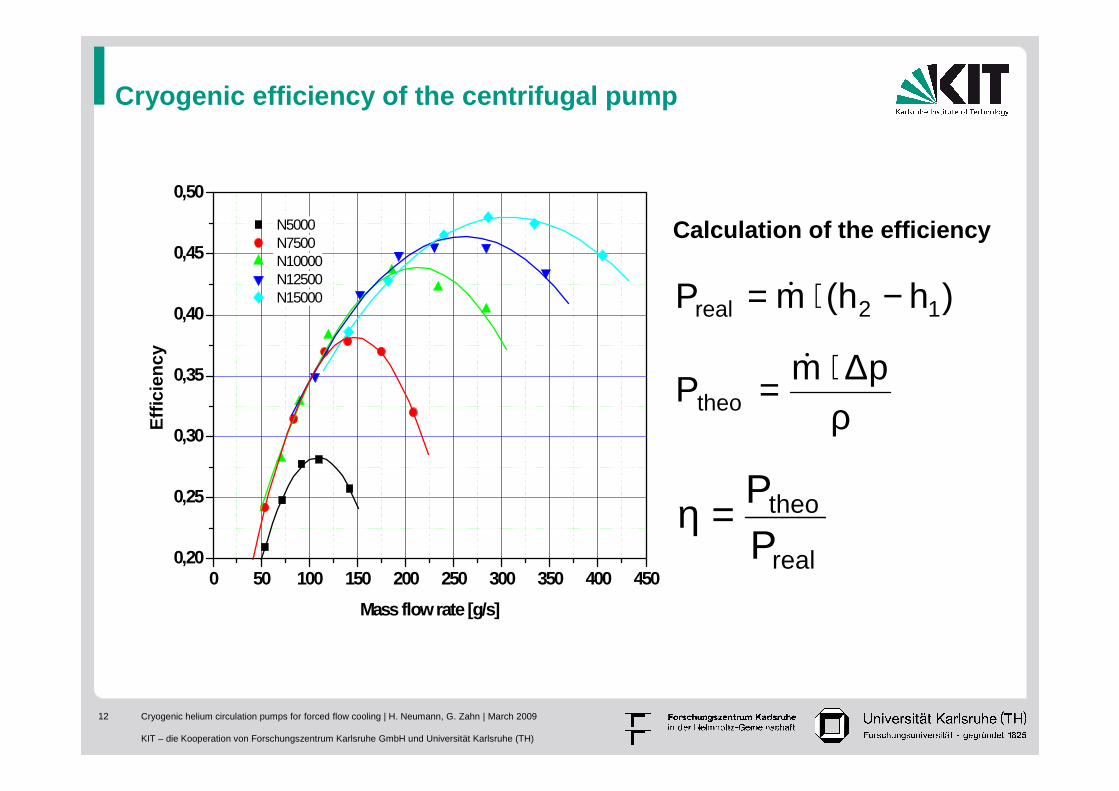
Cryogenic efficiency of the centrifugal pump
0 50 100 150 200 250 300 350 400 4500,20
0,25
0,30
0,35
0,40
0,45
0,50
Eff
icie
ncy
Mass flow rate [g/s]
N5000 N7500 N10000 N12500 N15000 )hh(mP 12real −⋅= &
ρ∆⋅= pm
Ptheo
&
real
theo
PP=η
Calculation of the efficiency

Cryogenic helium circulation pumps for forced flow cooling | H. Neumann, G. Zahn | March 2009
KIT – die Kooperation von Forschungszentrum Karlsruhe GmbH und Universität Karlsruhe (TH)
13
Cooling system of ITER including He circulation pumps
Cryogenic helium circulation pumps for forced flow cooling | H. Neumann, G. Zahn | March 2009
KIT – die Kooperation von Forschungszentrum Karlsruhe GmbH und Universität Karlsruhe (TH)
14
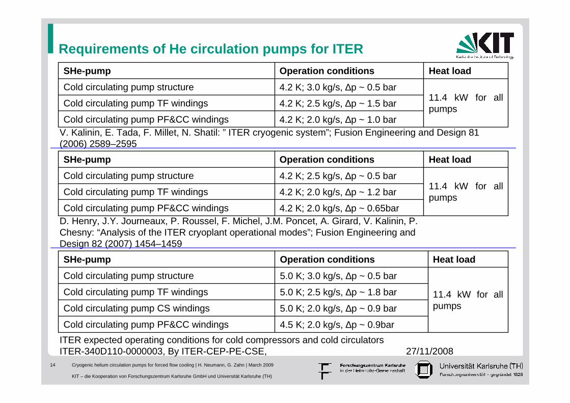
Requirements of He circulation pumps for ITER
D. Henry, J.Y. Journeaux, P. Roussel, F. Michel, J.M. Poncet, A. Girard, V. Kalinin, P.Chesny: “Analysis of the ITER cryoplant operational modes”; Fusion Engineering andDesign 82 (2007) 1454–1459
ITER expected operating conditions for cold compressors and cold circulatorsITER-340D110-0000003, By ITER-CEP-PE-CSE, 27/11/2008
4.5 K; 2.0 kg/s, ∆p ~ 0.9barCold circulating pump PF&CC windings
5.0 K; 2.0 kg/s, ∆p ~ 0.9 barCold circulating pump CS windings
5.0 K; 2.5 kg/s, ∆p ~ 1.8 barCold circulating pump TF windings 11.4 kW for all pumps
5.0 K; 3.0 kg/s, ∆p ~ 0.5 barCold circulating pump structure
Heat loadOperation conditionsSHe-pump
4.2 K; 2.0 kg/s, ∆p ~ 0.65barCold circulating pump PF&CC windings
4.2 K; 2.0 kg/s, ∆p ~ 1.2 barCold circulating pump TF windings11.4 kW for all pumps
4.2 K; 2.5 kg/s, ∆p ~ 0.5 barCold circulating pump structure
Heat loadOperation conditionsSHe-pump
4.2 K; 2.0 kg/s, ∆p ~ 1.0 barCold circulating pump PF&CC windings
4.2 K; 2.5 kg/s, ∆p ~ 1.5 barCold circulating pump TF windings11.4 kW for all pumps
4.2 K; 3.0 kg/s, ∆p ~ 0.5 barCold circulating pump structure
Heat loadOperation conditionsSHe-pump
V. Kalinin, E. Tada, F. Millet, N. Shatil: ” ITER cryogenic system”; Fusion Engineering and Design 81 (2006) 2589–2595
Cryogenic helium circulation pumps for forced flow cooling | H. Neumann, G. Zahn | March 2009
KIT – die Kooperation von Forschungszentrum Karlsruhe GmbH und Universität Karlsruhe (TH)
15
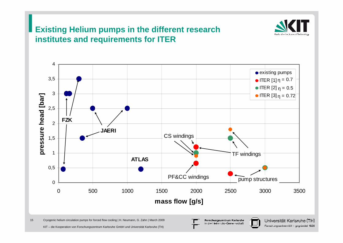
Existing Helium pumps in the different research institutes and requirements for ITER
0
0,5
1
1,5
2
2,5
3
3,5
4
0 500 1000 1500 2000 2500 3000 3500
mass flow [g/s]
pre
ssu
re h
ead
[b
ar]
existing pumps
ITER [1]
ITER [2]
ITER [3]
FZK
JAERI
ATLASTF windings
CS windings
PF&CC windings pump structures
η = 0.7
η = 0.5
η = 0.72
Cryogenic helium circulation pumps for forced flow cooling | H. Neumann, G. Zahn | March 2009
KIT – die Kooperation von Forschungszentrum Karlsruhe GmbH und Universität Karlsruhe (TH)
16
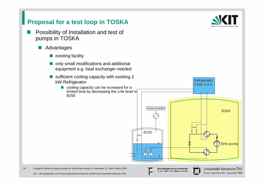
Proposal for a test loop in TOSKA
B300
SHe-pump
Refrigerator2 kW, 4.4 K
Possibility of Installation and test of pumps in TOSKA
Advantages
existing facility
only small modifications and additional equipment e.g. heat exchanger needed
sufficient cooling capacity with existing 2 kW-Refrigerator
cooling capacity can be increased for a limited time by decreasing the LHe level in B250
Gasometer
B250
Cryogenic helium circulation pumps for forced flow cooling | H. Neumann, G. Zahn | March 2009
KIT – die Kooperation von Forschungszentrum Karlsruhe GmbH und Universität Karlsruhe (TH)
17
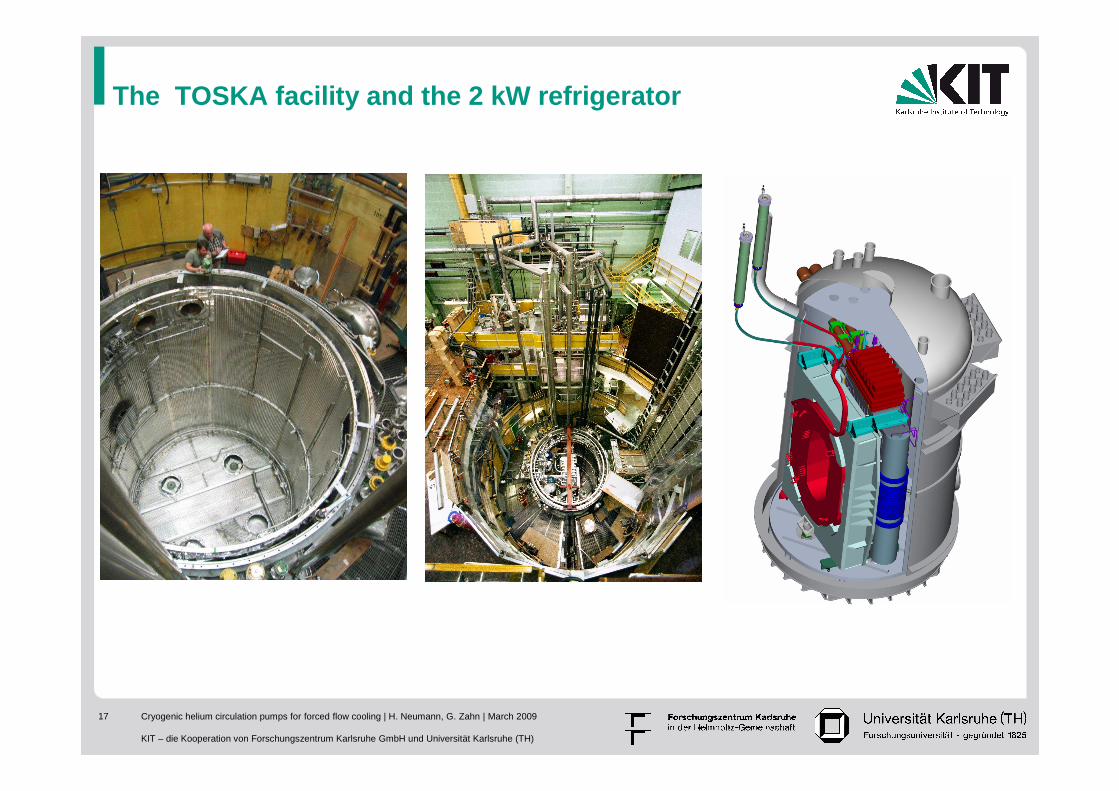
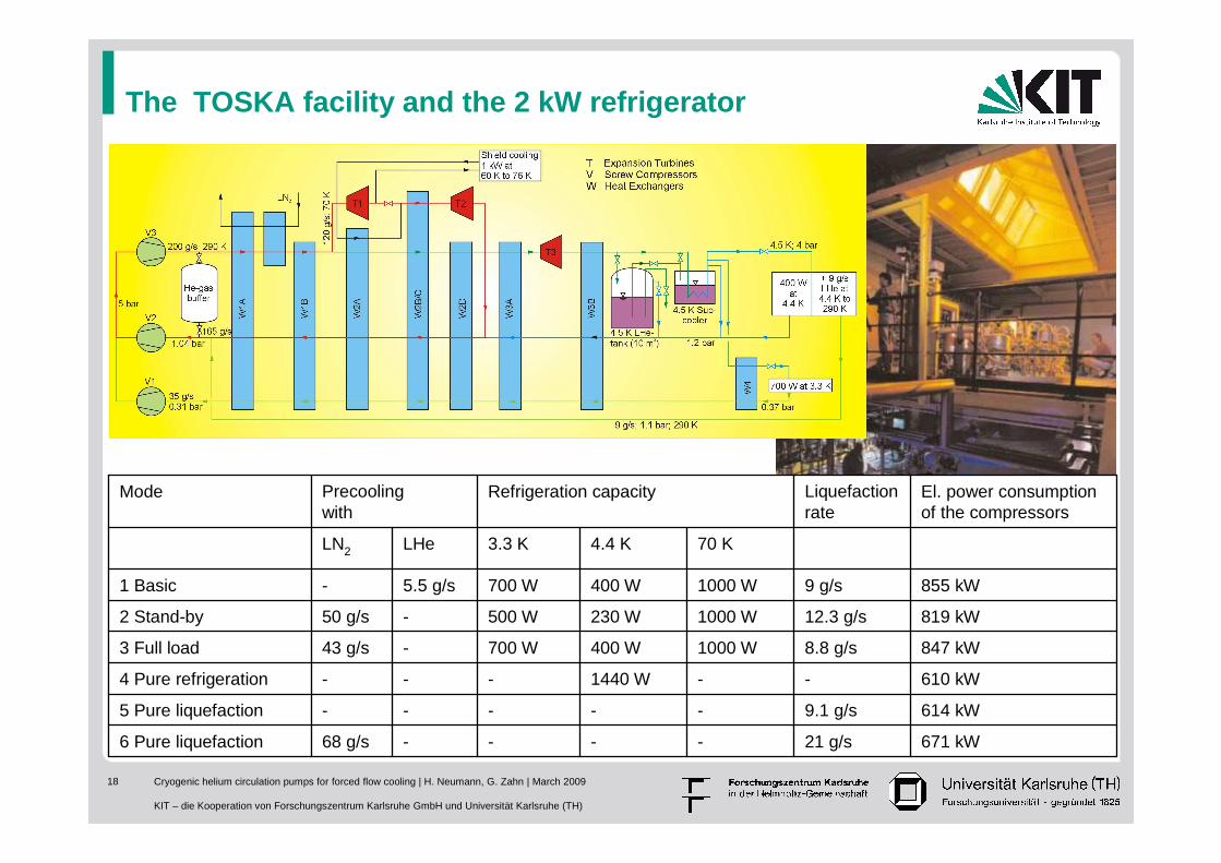
The TOSKA facility and the 2 kW refrigerator
Cryogenic helium circulation pumps for forced flow cooling | H. Neumann, G. Zahn | March 2009
KIT – die Kooperation von Forschungszentrum Karlsruhe GmbH und Universität Karlsruhe (TH)
18
The TOSKA facility and the 2 kW refrigerator
671 kW21 g/s----68 g/s6 Pure liquefaction
614 kW9.1 g/s-----5 Pure liquefaction
610 kW--1440 W---4 Pure refrigeration
847 kW8.8 g/s1000 W400 W700 W-43 g/s3 Full load
819 kW12.3 g/s1000 W230 W500 W-50 g/s2 Stand-by
855 kW9 g/s1000 W400 W700 W5.5 g/s-1 Basic
70 K4.4 K3.3 KLHeLN2
El. power consumption of the compressors
Liquefactionrate
Refrigeration capacityPrecoolingwith
Mode
Cryogenic helium circulation pumps for forced flow cooling | H. Neumann, G. Zahn | March 2009
KIT – die Kooperation von Forschungszentrum Karlsruhe GmbH und Universität Karlsruhe (TH)
19
Conclusion of the pump development
Each of the existing Helium circulation pumps was working very well sometimes for a long time
The mass flow rate of all the pumps used up to now is much below the requirements for ITER which are in the range between 1.5 kg/s to 3 kg/s
The cryogenic efficiency of the existing pumps is around 50 % but for ITER 70 % is mandatory
A development of a appropriate pump by industry is indispensable
The characteristic of the cooling system must be well known for an appropriate design of such a pump which should working in the region of high efficiency
The new developed Helium circulation pumps must be tested and ifnecessary optimized before installation in ITER

Cryogenic helium circulation pumps for forced flow cooling | H. Neumann, G. Zahn | March 2009
KIT – die Kooperation von Forschungszentrum Karlsruhe GmbH und Universität Karlsruhe (TH)
20
Thank youfor yourattention