
Cryogenic fluid behavior (with emphasis on normal helium)
25
Ram C. Dhuley USPAS – Cryogenic Engineering June 21 – July 2, 2021 Cryogenic fluid behavior (with emphasis on normal helium)
Transcript of Cryogenic fluid behavior (with emphasis on normal helium)

Ram C. Dhuley
USPAS – Cryogenic Engineering
June 21 – July 2, 2021
Cryogenic fluid behavior (with emphasis
on normal helium)

Goals of this lecture
• Familiarize with different types of flow and heat transfer systems in large scale helium cryogenics
• Learn engineering design parameters of cryogenic helium systems• Here we will focus only on normal helium• Superfluid helium and its properties will be covered in
another lecture.
• Briefly look at other common cryogens –nitrogen, argon
2 Ram C. Dhuley | USPAS Cryogenic Engineering (Jun 21 - Jul 2, 2021)
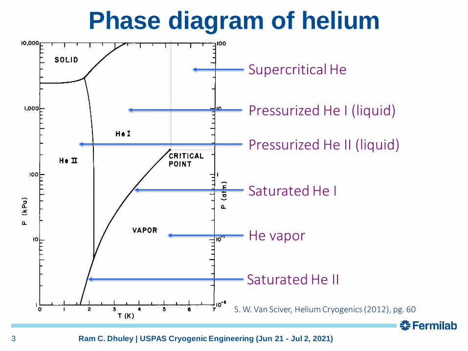
Phase diagram of helium
3 Ram C. Dhuley | USPAS Cryogenic Engineering (Jun 21 - Jul 2, 2021)
S. W. Van Sciver, Helium Cryogenics (2012), pg. 60
Supercritical He
Pressurized He I (liquid)
Pressurized He II (liquid)
Saturated He I
He vapor
Saturated He II

Accelerator magnets are often cooled with pressurized liquid or forced flow of supercritical helium• gives maximum penetration
of helium mass in magnet coils
• crucial for thermal stability since the coils operate near the superconductivity limit
Tevatron
SSC
LHC
4 Ram C. Dhuley | USPAS Cryogenic Engineering (Jun 21 - Jul 2, 2021)
Cooling modes in large
helium cryogenic systems
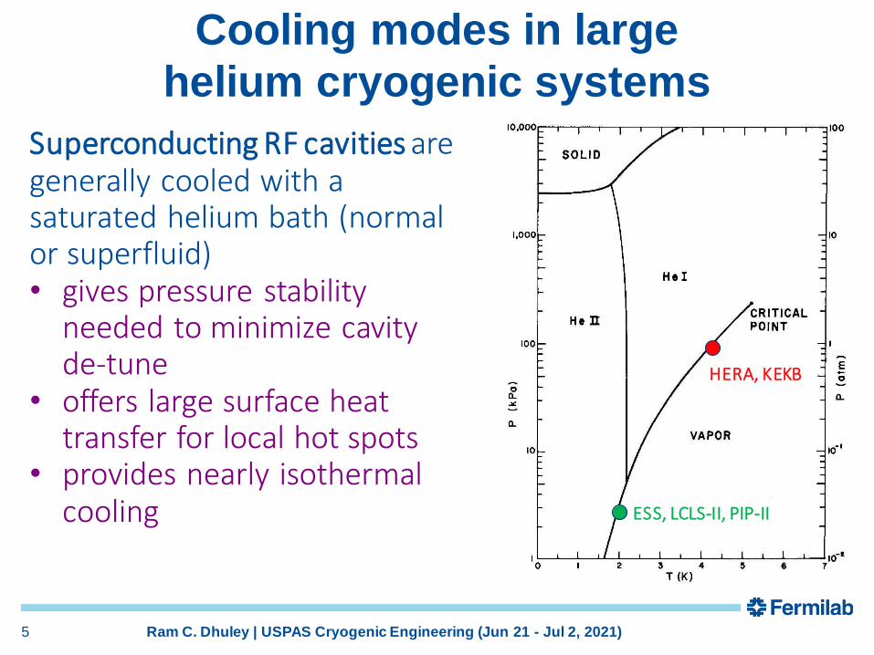
HERA, KEKB
ESS, LCLS-II, PIP-II
5 Ram C. Dhuley | USPAS Cryogenic Engineering (Jun 21 - Jul 2, 2021)
Superconducting RF cavities are generally cooled with a saturated helium bath (normal or superfluid)• gives pressure stability
needed to minimize cavity de-tune
• offers large surface heat transfer for local hot spots
• provides nearly isothermal cooling
Cooling modes in large
helium cryogenic systems

Helium cooling modes - examples
6 Ram C. Dhuley | USPAS Cryogenic Engineering (Jun 21 - Jul 2, 2021)
12
3
Re-cooler scheme for accelerator SC magnets. Modes present:1. Subcooled liquid helium flow2. Convection/nucleate boiling heat transfer3. Single phase vapor flow

Helium cooling modes - examples
7 Ram C. Dhuley | USPAS Cryogenic Engineering (Jun 21 - Jul 2, 2021)
Bayonet heat exchangers for LHC superconducting magnets. Modes present:
1. Two phase He II flow2. Single phase vapor flow3. Surface heat transfer to He II (Kapitza mode)
Magnet Magnet Magnet Magnet
12
3

Helium cooling modes - examples
8 Ram C. Dhuley | USPAS Cryogenic Engineering (Jun 21 - Jul 2, 2021)
Saturated helium bath cooling of superconducting radiofrequency accelerator cavities
Modes present:1. Single phase vapor
flow2. Two-phase flow
(during bath fill)3. Surface heat transfer
(Kapitza or nucleate boiling)
1
2
3
Fill line

9 Ram C. Dhuley | USPAS Cryogenic Engineering (Jun 21 - Jul 2, 2021)
Helium cooling modes - examples
Distribution of cryogenic helium. Modes present:1. Supercritical helium flow2. Two phase flow3. Single phase vapor flow4. Heat transfer (heat leak)
Helium cryoplant
SC device being cooled
Supply and return pipelines(can be very long, several 100 m)
JT valve
1 2
3
4

10 Ram C. Dhuley | USPAS Cryogenic Engineering (Jun 21 - Jul 2, 2021)
Helium cooling modes - summary
• As seen in the prior examples, a large-scale helium cryogenic system will typicallyinvolve several flow and heat transfer modes operating in parallel
• What are the engineering parameters one should know to be able to design such helium cryosystems?

Engineering design parameters
Expression assumes helium behaves as ideal gas and has small flow velocity.(See Helium Cryogenics chapter 4 for details)
Compressor/pump power required for circulating helium depends on the pressure drop in the circuit:
Friction factor, fF determines the frictional pressure drop:- Type of flow – single phase, two-phase- Flow regime – laminar, turbulent, mixedHeat leak, q determines the acceleration pressure drop:- Relevant to compressible (gas/supercritical) and two-phase
flows
11 Ram C. Dhuley | USPAS Cryogenic Engineering (Jun 21 - Jul 2, 2021)

Engineering design parameters
( )load c load fluidQ h A T T= −
Heat transfer coefficient, hc determines the effectiveness of heat transfer from the load to the fluid- Mode of heat transfer – forced, natural convection, pool
boiling- Flow regime/type – laminar, turbulent, single/two-phase- Boiling regime – nucleate, film
12 Ram C. Dhuley | USPAS Cryogenic Engineering (Jun 21 - Jul 2, 2021)
Superconducting device stability/performance depends on the effectiveness of heat transfer to the helium coolant:
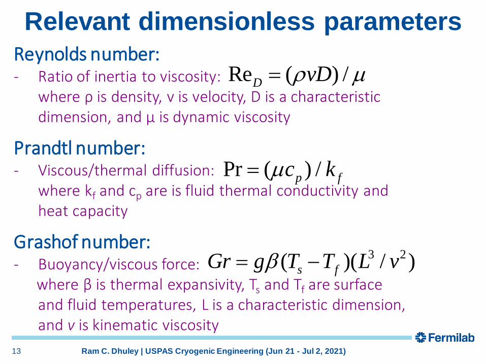
Relevant dimensionless parametersReynolds number:- Ratio of inertia to viscosity:
where ρ is density, v is velocity, D is a characteristicdimension, and µ is dynamic viscosity
Re ( ) /D vD =
Prandtl number:- Viscous/thermal diffusion:
where kf and cp are is fluid thermal conductivity and heat capacity
Pr ( ) /p fc k=
Grashof number:- Buoyancy/viscous force:
where β is thermal expansivity, Ts and Tf are surface and fluid temperatures, L is a characteristic dimension, and v is kinematic viscosity
3 2( )( / )s fGr g T T L v= −
13 Ram C. Dhuley | USPAS Cryogenic Engineering (Jun 21 - Jul 2, 2021)

Relevant dimensionless parameters
Nusselt number:- For forced convection:
- For natural convection:
- Required for calculating convective heat transfer coefficient, h
( ,Pr) ( ) /L fNu func Gr hL k= =
(Re ,Pr) ( ) /D D fNu func hD k= =
Friction factor: (Re )F Df func=
- Required for calculating pressure drop in a channel with forced flow
14 Ram C. Dhuley | USPAS Cryogenic Engineering (Jun 21 - Jul 2, 2021)
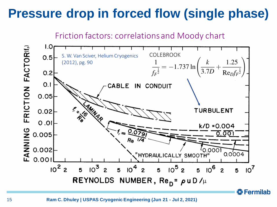
Pressure drop in forced flow (single phase)
Friction factors: correlations and Moody chart
S. W. Van Sciver, Helium Cryogenics (2012), pg. 90
15 Ram C. Dhuley | USPAS Cryogenic Engineering (Jun 21 - Jul 2, 2021)

Pressure drop in forced flow (two phase)
Because of low heat of vaporization, single phase LHe flow in a long pipe can quickly become two phase from a heat in-flow to the pipe.
q
LHe
How to estimate the pressure drop in two-phase helium flow?
J. C. Theilacker and C. H. Rode, An Investigation into Flow Regimes for Two-phase Helium Flow, Adv. Cryo. Eng. 33, 391, 1988.
• Baker plots are used for two phase calculations of oil + gas, air + water flows.
• Work of Theilacker and Rode (1988) showed that Baker plot is not suitable for representing helium two-phase flows.
• Use Lockhart-Martinelli type approach (next slide).
16 Ram C. Dhuley | USPAS Cryogenic Engineering (Jun 21 - Jul 2, 2021)

S. W. Van Sciver, Helium Cryogenics (2012), pg. 104
Pressure drop in forced flow (two phase)
2) Calculate homogenous model two-phase multiplier
A few experiments have found that the Lockhart-Martinelli type approach with homogenous flow model shows reasonable agreement with data.
3) Calculate two-phase pressure drop
17 Ram C. Dhuley | USPAS Cryogenic Engineering (Jun 21 - Jul 2, 2021)
1) Calculate liquid-phase pressure dropusing appropriate
single phase correlation
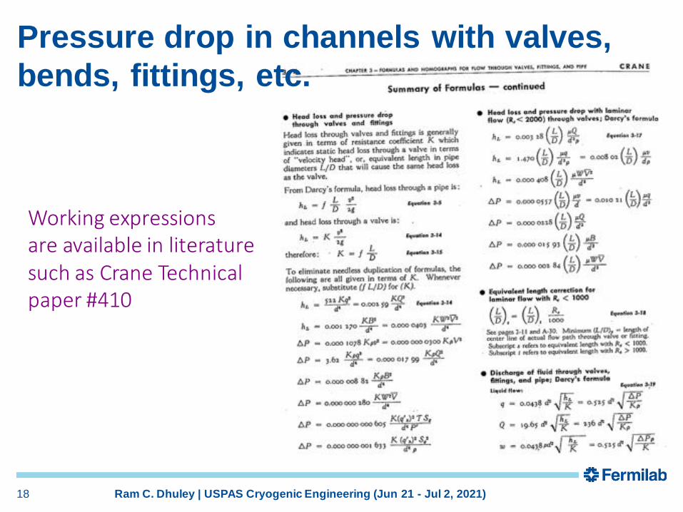
Pressure drop in channels with valves,
bends, fittings, etc.
Working expressionsare available in literaturesuch as Crane Technical paper #410
18 Ram C. Dhuley | USPAS Cryogenic Engineering (Jun 21 - Jul 2, 2021)
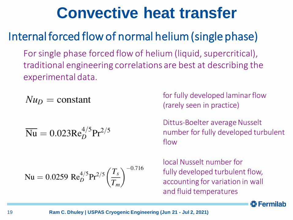
Convective heat transfer
Internal forced flow of normal helium (single phase)
For single phase forced flow of helium (liquid, supercritical), traditional engineering correlations are best at describing the experimental data.
for fully developed laminar flow(rarely seen in practice)
Dittus-Boelter average Nusselt number for fully developed turbulent flow
local Nusselt number for fully developed turbulent flow,accounting for variation in wall and fluid temperatures
19 Ram C. Dhuley | USPAS Cryogenic Engineering (Jun 21 - Jul 2, 2021)
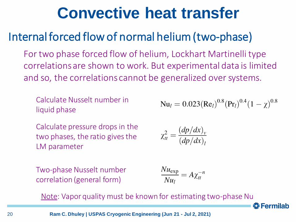
Convective heat transfer
Internal forced flow of normal helium (two-phase)
For two phase forced flow of helium, Lockhart Martinelli typecorrelations are shown to work. But experimental data is limited and so, the correlations cannot be generalized over systems.
Calculate Nusselt number in liquid phase
Calculate pressure drops in the two phases, the ratio gives the LM parameter
Two-phase Nusselt number correlation (general form)
Note: Vapor quality must be known for estimating two-phase Nu
20 Ram C. Dhuley | USPAS Cryogenic Engineering (Jun 21 - Jul 2, 2021)

Convective heat transfer
Pool boiling in normal liquid helium
The normal He pool boiling curve is like thatfor conventional liquids• Convection • Nucleate boiling• Film boiling • Recovery with hysteresis
S. W. Van Sciver, Helium Cryogenics (2012), pg. 118
Onset of nucleate boiling
Transition to film Boiling (CHF, q*)
Recovery from film boiling
Transition heat fluxes and the associated superheats are small• Onset nucleate boiling: ~0.1 K, ~1e-3 W/cm2
• Transition to film boiling: ~1 K, q* ~1 W/cm2
• Recovery from film boiling: ~0.1 W/cm2
(~ten-fold smaller than CHF)
21 Ram C. Dhuley | USPAS Cryogenic Engineering (Jun 21 - Jul 2, 2021)
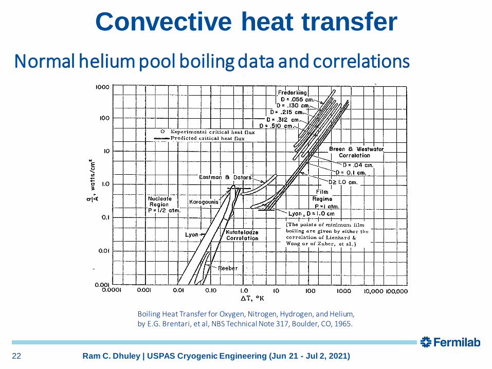
Convective heat transfer
Boiling Heat Transfer for Oxygen, Nitrogen, Hydrogen, and Helium, by E.G. Brentari, et al, NBS Technical Note 317, Boulder, CO, 1965.
Normal helium pool boiling data and correlations
22 Ram C. Dhuley | USPAS Cryogenic Engineering (Jun 21 - Jul 2, 2021)

Other cryogens
Nitrogen and argon are other commonly used cryogens in large scale systems• Liquid nitrogen is commonly used to cool 75-80 K
thermal radiation shields around helium baths/pipes
• Liquid argon is used in time projection chamber (eg. neutrino detector in Fermilab DUNE)
23 Ram C. Dhuley | USPAS Cryogenic Engineering (Jun 21 - Jul 2, 2021)
Since both nitrogen and argon are normal fluids, most pressure drop and heat transfer correlations discussed earlier apply respectively to their flow and heat transfer modes.

Nitrogen pool boiling data and correlations
24 Ram C. Dhuley | USPAS Cryogenic Engineering (Jun 21 - Jul 2, 2021)
References and further reading
• S. W. Van Sciver, “Helium Cryogenics,” Plenum Press, 1986.
• Ovid Baker, "Design of Pipelines for the Simultaneous Flow of Oil and Gas," Oil and Gas Journal (July 26, 1954) p. 185-195.
• J. C. Theilacker and C. H. Rode, “An Investigation into Flow Regimes for Two-phase Helium Flow,” Advances in Cryogenic Engineering, Vol. 33, pp. 391-398, 1988.
• E.G. Brentari, et al, “Boiling Heat Transfer for Oxygen, Nitrogen, Hydrogen, and Helium,” NBS Technical Note 317, Boulder, CO, 1965.
• Crane Technical Paper #410 “Flow of Fluids through Valves, Fittings, and Pipes”.
25 Ram C. Dhuley | USPAS Cryogenic Engineering (Jun 21 - Jul 2, 2021)