Cryogenic Refrigerator - qd-china.comAny duplication of this manual or any of its parts without...
78
Cryogenic Refrigerator INSTALLATION, OPERATION and ROUTINE MAINTENANCE MANUAL
Transcript of Cryogenic Refrigerator - qd-china.comAny duplication of this manual or any of its parts without...

Cryogenic Refrigerator
INSTALLATION, OPERATION and ROUTINE MAINTENANCE MANUAL

The information contained in this document is believed to be accurate and reliable as of the time of its publication. However, Cryomech, Inc. cannot accept any responsibility (financial or otherwise) that may result from the use or misuse of the information contained in this document. Except as expressly contained in this document, there are no other warranties granted or extended by the manufacturer.
Cryomech, Inc. reserves the right to add, change, modify or delete any or all information contained herein without prior written notice. Revisions to this document may be issued at the time such changes and/or deletions occur.
Any duplication of this manual or any of its parts without expressed written permission from Cryomech, Inc. is expressly prohibited.
Correspondence concerning this document should be forwarded to:
Customer Service Department Cryomech, Inc. 113 Falso Drive Syracuse, NY 13211 USA
Telephone (315) 455-2555 FAX: (315) 455-2544 Email: [email protected]
Website: www.cryomech.com

Contents Section 1
Overview
Section 2 Warranty
Section 3 Safety
Section 4 Inspection and Unpacking
Section 5 Specifications
Section 6 Installation
Section 7 Operation
Section 8 Routine Maintenance
Appendix A
Appendix B Spray Lubricant Instructions

Section 1
Overview

Overview
Section 1: Overview This section provides an overview discussion of Cryomech Cryorefrigerators. It also provides an overview of this manual, including the organization, basic definitions of terms used and expansion of acronyms used in the manual.
1.1 Cryogenic refrigeration system
1.1.1 General description
The operation of a cryogenic refrigeration system is based on a closed-loop helium expansion cycle. A complete system consists of two major components: one is the compressor package, which compresses refrigerant and removes heat from the system; the other is the cold head, which takes refrigerant through one or more additional expansion cycles to cool it down to cryogenic temperatures. The refrigerant gas used in the Cryomech cryogenic systems is 99.999% pure helium. Flexible stainless steel lines called helium flex lines carry compressed helium from the compressor package to the cold head and carry low-pressure helium back.
The compressor package works as follows. An oil-lubricated compressor compresses the pure low-pressure helium that is returned from the cold head. The heat of compression is removed via a heat exchanger, and the oil from the compression process is removed in a series of oil separators and filters. The compressed helium is then fed to the cold head via the high-pressure helium flex line.
In the cold head, adiabatic expansion of the helium and further heat removal allows cooling to cryogenic temperatures. The low-pressure helium then returns to the compressor package via the low-pressure helium flex line.
1.1.2 Features and benefits of the Cryomech Pulse Tube Cold Head
The Cryomech Pulse Tube Cold Head has been carefully designed and manufactured to provide years of trouble free service.
Primary features
The unique feature of pulse tubes is that the expansion of the helium in the cold head is done with out a displacer or piston. This results in a cold head that has no moving parts at cryogenic temperatures, no seals and no motion of the regenerative materials.
Primary benefits
• Very low vibration • High reliability • Long mean time between maintenance • Reduced magnetic fluctuation from rare earth materials • Lower costs of operation and maintenance
1-1

Overview
1.1.3 Features and benefits of the Cryomech Compressor
Primary features
The CP2800 and CP1000 Series Compressor Packages include a microprocessor control with the following features:
• Fault sensing
• Automatic error logging
• Remote operation
• Remote indication of faults
• Phase error sensing
Primary benefits
• The microprocessor control prevents reverse operation
• The compressors can be operated and monitored from a remote location
1.2 Cryomech Cryorefrigerator Manual This manual covers the complete Cryomech Cryorefrigerator that consists of the Pulse Tube Cold Head, the Helium Compressor Package, a cold head motor cord and a set of helium flex lines.
It is important that you review this manual carefully before beginning the installation process.
1.2.1 Organization of the manual
The main body of the manual provides a detailed discussion of everything you will need in order to install and operate the Cryomech Cryorefrigerator and to perform routine maintenance. It is divided into 8 sections. Illustrations accompany the discussion as needed for clarification. Additional information will be in the appendix.
Numbered lists labeled with 1), 2), etc and lettered lists labeled with a., b., etc. are used for sequential actions that must be performed in the order listed. Lists for which order is not important are bulleted, using solid or hollow bullets.
The manual contains essential information for the safe and effective operation of your Cryomech Cryorefigerator. Sections 2 and 3 clearly lay out all safety precautions you should take and also explain the ways in which you might inadvertently void your warranty by doing something that would damage the system.
Sections 4 through 8 provide complete step-by-step instructions on the handling of your Cryomech Cryorefrigerator, from inspection of the packing crate through routine maintenance. Each safety precaution is also shown in these sections in every place where observing the caution or warning is important.
• Section 1: Overview (including definitions and acronyms)
• Section 2: Warranty
• Section 3: Safety
• Section 4: Inspection and unpacking
• Section 5: Specifications
1-2
Overview
• Section 6: Installation
• Section 7: Operation
• Section 8: Routine maintenance
• Appendix: Additional information
1.2.2 Related documents
Technical manual
A separate detailed technical manual will be available by contacting Cryomech. This manual covers the theory behind cryorefrigerators, and supplies detailed information on optimizing instrumentation and insulation of cold heads for maximum performance.
1.3 Glossary
1.3.1 Definitions
The terms defined below are used with precision in the manual. For example, distinction is made between the (cryorefrigerator) system, the (compressor) package, and the (compressor) module.
The terms are in alphabetical order, and italicized terms within the definitions are terms that are also defined in this section.
Aeroquip® Couplings:
The term "Aeroquip® couplings" is used generically to describe the self-sealing fittings that connect components e.g. that connect helium flex lines to the compressor package and helium flex lines to the cold head.
Category II Installation:
Category II refers to the potential for transient over-voltage conditions in the mains power connection to the equipment. See IEC 664, Sub-clause 5.6 for further details.
Closed Loop System:
This refers to a cryogenic system that has no helium loss because the helium is cycled through a closed loop. The advantage of such a system is that there is no need to add helium.
Cold Head:
The cold head is an expansion device, which is capable of reaching cryogenic temperatures. In the AL or GB systems the cold head is a Gifford-McMahon style unit. In the PT series systems the cold head is a Pulse Tube style unit.
Cold Head Motor Cord
The cold head motor cord is pre-wired and fitted with electrical connectors on each end that attach to the cold head and compressor package. The cold head motor cord provides electrical power from the compressor package to the cold head motor.
Compressor Module:
Located inside the compressor package, the compressor module is an oil-lubricated commercial compressor that compresses low-pressure helium to the necessary high pressure.
1-3
Overview
Compressor Package:
The compressor package houses the compressor module and all other components that cool and purify helium and that provide system safety control. The compressor package compresses the low-pressure helium returning from the cold head and provides clean high-pressure helium to the cold head.
Cryogenic Temperatures:
Temperatures lower than 120K or -153°C.
Cryorefrigerator (Cryocooler):
A cryorefrigerator is a cryogenic refrigeration system based upon a closed loop helium expansion cycle. It consists of a compressor package, helium flex lines and a cold head (expansion device).
Cold Head Heat Exchanger:
The heat exchanger(s) on the cold head provide cooling at cryogenic temperatures by transferring heat to the helium within the system.
Gifford-McMahon (GM) Cryorefrigerator
A Gifford-McMahon cryorefrigerator is a cryorefrigerator in which the cold head expands the helium using a displacer or piston.
Helium Flex Lines:
The helium flex lines are corrugated stainless steel hoses that transport helium between the compressor package and the cold head.
Nitrogen Flexible Lines or Flex Lines:
Nitrogen flex lines are corrugated stainless steel hoses that carry nitrogen. These lines only apply to Liquid Nitrogen Plant models.
Pollution Degree 2:
Pollution degree 2 refers to the extent to which the local environmental conditions could affect the electrical safety of the system. See EN 61010 or UL 61010A for further details.
Pulse Tube Cryorefrigerator:
A pulse tube cryorefrigerator is a cryorefrigerator in which the cold head expands the helium using a pulse tube instead of a displacer or piston.
System:
The term "system" is used as a synonym for cryorefrigerator. It consists of a compressor package, helium flex lines and cold head.
1.3.2 Acronyms
The following acronyms are used in the text and provided here for convenient lookup.
FPT Female Pipe Thread
GPM Gallons per Minute
LPM Liters per Minute
MPT Male Pipe Thread
OFHC Oxygen-Free High Conductivity (describes a form of Copper)
PSIG Pounds per Square Inch Gauge
1-4

Overview
1.4 Cryomech Contact Information Cryomech, Inc. 113 Falso Drive Syracuse, NY 13211
Phone: (315) 455-2555 Fax: (315) 455-2544 Email: [email protected]
Website: www.cryomech.com
1-505Feb07
Section 2
Warranty

Warranty
Section 2: Warranty
2.1 Statement of warranty Provided that the customer installs, operates and maintains this cryorefrigerator according to the specifications and procedures set forth in this manual, Cryomech, Inc. extends a warranty on all parts and workmanship for a period of three (3) years or 12,000 operating hours, whichever comes first. This warranty covers all non-user serviceable components of the compressor package, the cold head and the helium flex lines. The warranty does not cover user-serviceable parts (such as fuses).
If found to be defective and in accordance with the terms of the limited warranty, Cryomech will provide warranty replacement parts at no cost to the customer. Customers are responsible for all shipping and handling charges associated with warranty repair.
The Pulse Tube Cold Head is also warranted for the same three (3) years or period of 12,000 operating hours to deliver the specified temperatures and cooling capacities.
2.2 Conditions that can void the warranty • Operation of the cryorefrigerator in any situation that does not meet the specifications
in this section will void the warranty. If you plan to operate the system outside any of the specified conditions, contact Cryomech. See Section 5.
• Failure to follow these installation guidelines could result in voiding the warranty. See Section 6.
• Because the tubes in the cold head must have very thin walls for cryogenic performance, extreme care must be taken when handling the cold head. Take special care to not dent or bend the tube assemblies. The warranty will not cover dented or bent tubes. See Section 6.
• Operating the cold head in a magnetic field of greater than 500 gauss will void the warranty. See Sections 6 and 7.
• Do not apply heat directly to the cold head (e.g. soldering anything to the cold head heat exchanger(s)). Doing so will damage the cold head and void the warranty. The warranty will not cover heating of the cold head over 325K (125ºF, 52ºC). See Section 6.
• In some applications, heavy components must be mounted to the cold surface. With the cold head oriented vertically, the maximum allowable load cannot exceed the value specified in Section 5. If your application requires a heavier load or an orientation other than vertical with a load, please contact Cryomech. An excessive load on the cold head can damage the tubes. This type of damage is not covered under the warranty. See Section 6.
• If the bolt pattern on the heat exchanger needs to be changed, you must consult Cryomech first to learn how to prevent damage to the cold head. Holes drilled without prior approval from Cryomech will void the warranty. See Section 6.
• Cooling water must meet the requirements in Section 5. If water that does not meet the cooling water specifications in Section 5 is introduced into the system, even for cleaning purposes, it will void the warranty. See Section 6.
2-1

Warranty
• A voltage deviation of more than 10% above or below the voltage rating can cause compressor motor overheating and possible failure. Indications of operation outside that voltage range will void the compressor warranty. See Sections 6 and 7.
• Do not allow the flex lines to come into contact with corrosives or any type of commercial cleaning agent. Helium leaks caused by exposure to corrosives or commercial cleaning agents will not be covered under warranty. See Section 6.
• Do not bend the flex lines to less than 10 inch (25 cm) radius or permanent damage may occur. This type of damage is not covered under the warranty. See Section 6.
• CP900 Series Compressors Only - Running the CP900 Compressor Package in reverse will void the warranty. If the power cord is not wired properly the compressor will run in reverse and there will be no pressure differential on the pressure gauges. Turn the system off immediately. See Section 7.
• The cold head contains no user-serviceable parts. Attempting to disassemble the cold head will void the warranty. Contact Cryomech if the cold head needs to be returned for servicing. See Section 8.
• When adding helium, the helium must be 99.999% pure. Contamination by other gases will result in the freezing of the contaminant gases in the cold head because their freezing temperature is much higher than that of helium. Contaminants in the helium charge will severely degrade the cold head’s function and it will require factory servicing. Contamination of the helium by other gases is a common cause of premature failure and, unless resulting from a system failure, is not covered by the warranty. See Section 8.
• Never wet either part of the system. Water getting into the system will void the warranty. See Section 8.
2-205Feb07

Section 3
Safety
Safety
Section 3: Safety
3.1 Safety and information symbols
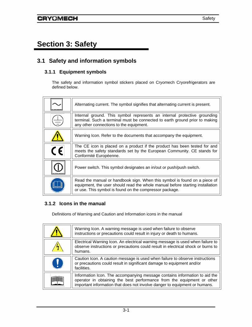
3.1.1 Equipment symbols
The safety and information symbol stickers placed on Cryomech Cryorefrigerators are defined below.
Alternating current. The symbol signifies that alternating current is present.
Internal ground. This symbol represents an internal protective grounding terminal. Such a terminal must be connected to earth ground prior to making any other connections to the equipment.
Warning Icon. Refer to the documents that accompany the equipment.
The CE icon is placed on a product if the product has been tested for and meets the safety standards set by the European Community. CE stands for Conformité Européenne.
Power switch. This symbol designates an in/out or push/push switch.
Read the manual or handbook sign. When this symbol is found on a piece of equipment, the user should read the whole manual before starting installation or use. This symbol is found on the compressor package.
3.1.2 Icons in the manual
Definitions of Warning and Caution and Information icons in the manual
Warning Icon. A warning message is used when failure to observe instructions or precautions could result in injury or death to humans.
Electrical Warning Icon. An electrical warning message is used when failure to observe instructions or precautions could result in electrical shock or burns to humans.
Caution Icon. A caution message is used when failure to observe instructions or precautions could result in significant damage to equipment and/or facilities.
Information Icon. The accompanying message contains information to aid the operator in obtaining the best performance from the equipment or other important information that does not involve danger to equipment or humans.
3-1

Safety
3.2 Warnings and cautions Warnings and cautions for the Cryomech Cryorefrigerator system are listed here by subsystem. The same warnings and cautions appear in the appropriate places in the unpacking, installation, operation and routine maintenance sections of this document.
3.2.1 Section 5. Specifications
Section 5.2 Technical specifications
CAUTION Operation of the cryorefrigerator in any situation that does not meet the specifications in this section will void the warranty. If you plan to operate the system outside any of the specified conditions, contact Cryomech.
3.2.2 Section 6. Installation
Section 6.1 Cold head installation
CAUTION Failure to follow these installation guidelines could result in voiding the warranty.
CAUTION Because the tubes in the cold head must have very thin walls for cryogenic performance, extreme care must be taken when handling the cold head. Take special care to not dent or bend the tube assemblies. The warranty will not cover dented or bent tubes.
CAUTION Operating the cold head in a magnetic field of greater than 500 gauss will void the warranty.
Section 6.1.2 Initial preparation of the cold head
CAUTION Because the tubes in the cold head must have very thin walls for cryogenic performance, extreme care must be taken when handling the cold head. Take special care to not dent or bend the tube assemblies. The warranty will not cover dented or bent tubes.
3-2
Safety
CAUTION Do not apply heat directly to the cold head (e.g. soldering anything to the heat exchanger(s)). Doing so will damage the cold head and void the warranty. The warranty will not cover heating of the cold head over 325K (125ºF, 52ºC).
CAUTION In some applications, heavy components must be mounted to the cold surface. With the cold head oriented vertically, the maximum allowable load cannot exceed the value specified in Section 5. If your application requires a heavier load or an orientation other than vertical with a load, please contact Cryomech. An excessive load on the cold head can damage the tubes. This type of damage is not covered under the warranty.
CAUTION If the bolt pattern on the heat exchanger needs to be changed, you must consult Cryomech first to learn how to prevent damage to the cold head. Holes drilled without prior approval from Cryomech will void the warranty.
Section 6.1.6 Connect the remote motor assembly’s flex line- REMOTE MOTOR COLD HEADS ONLY
CAUTION Follow the procedure carefully when connecting and disconnecting the helium flex lines. Failure to follow the procedure can cause accidental coupling disassembly, destruction of the sealing O-ring, and helium loss.
CAUTION Do not allow the flex lines to come into contact with corrosives or any type of commercial cleaning agent. Helium leaks caused by exposure to corrosives or commercial cleaning agents will not be covered under warranty.
CAUTION Do not bend the flex lines to less than 10 inch (25 cm) radius or permanent damage may occur. This type of damage is not covered under the warranty.
Section 6.2 Compressor installation
CAUTION Failure to follow these installation guidelines could result in voiding the warranty.
3-3

Safety
Section 6.2.1 Prepare the compressor package location
WARNING The compressor package must be positioned to provide easy access to the front-panel mounted circuit breaker.
Section 6.2.2 Connect the water lines to the compressor
CAUTION Cooling water must meet the requirements in Section 5. If water that does not meet the cooling water specifications in Section 5 is introduced into the system, even for cleaning purposes, it will void the warranty.
CAUTION Do not apply heat to the cooling water inlet and outlet connectors located on the front panel of the compressor.
Section 6.2.3 Connect the compressor package to the main power
CAUTION A voltage deviation of more than 10% above or below the voltage rating can cause compressor motor overheating and possible failure. Indications of operation outside that voltage range will void the compressor warranty.
WARNING Be sure to follow all local electrical codes and guidelines.
WARNING One lead of the compressor package is grounded. Never bypass this ground or attach the compressor package to an ungrounded circuit. A dangerous electrical hazard will develop.
Section 6.2.4 Connect the helium flex lines to the cold head or remote motor assembly and the compressor package
CAUTION Follow the procedure carefully when connecting and disconnecting the helium flex lines. Failure to follow the procedure can cause accidental coupling disassembly, destruction of the sealing O-ring, and helium loss.
3-4
Safety
CAUTION Do not allow the flex lines to come into contact with corrosives or any type of commercial cleaning agent. Helium leaks caused by exposure to corrosives or commercial cleaning agents will not be covered under warranty.
CAUTION Do not bend the flex lines to less than 10 inch (25 cm) radius or permanent damage may occur. This type of damage is not covered under the warranty.
WARNING Never remove the Aeroquip® couplings from the helium flex lines without first relieving the helium charge in the line to acceptable levels. The pressure in the hose can blow off the coupling with sufficient force to cause injury.
3.2.3 Section 7. Operation
Section 7.1.1 Checks before operating
CAUTION A voltage deviation of more than 10% above or below the voltage rating can cause compressor motor overheating and possible failure. Indications of voltage operation outside that range will void the compressor warranty.
CAUTION Operating the cold head in a magnetic field of greater than 500 gauss will void the warranty.
Section 7.1.2 Startup procedure – CP900 SERIES COMPRESSOR PACKAGES ONLY
CAUTION Running the CP900 Compressor Package in reverse for any significant length of time will void the warranty. If the power cord is not wired properly the compressor will run in reverse and there will be no pressure differential on the pressure gauges. Turn the system off immediately. Follow the instructions in Step 4, below, to rewire the power cord correctly.
3-5

Safety
Section 7.5 Disassembling the system for transport or storage
WARNING Do not touch the cold end of the cold head until it has warmed to room temperature. If there is frost on the cold head, it is too cold to touch.
3.2.4 Section 8. Routine maintenance
Section 8.3 Cold head
CAUTION The cold head contains no user-serviceable parts. Attempting to disassemble the cold head will void the warranty. CONTACT CRYOMECH IF THE COLD HEAD NEEDS TO BE RETURNED FOR SERVICING.
Section 8.4 Replace the adsorber
CAUTION At no time should the Aeroquip® couplings be removed from the adsorber when replacing the adsorber. Replacement can be completed without relieving system pressure since the adsorber is equipped with Aeroquip® couplings for sealed removal.
Section 8.5 Vent excess helium
CAUTION Venting more than 5 PSIG (.34 bar) of helium per minute will lead to improper oil migration within the system. If this condition occurs, factory service will be required.
Section 8.6 Recharge helium
CAUTION When adding helium, the helium must be 99.999% pure. Contamination by other gases will result in the freezing of the contaminant gases in the cold head because their freezing temperature is much higher than that of helium. Contaminants in the helium charge will severely degrade the cold head's function and it will require factory servicing. Contamination of the helium by other gases is a common cause of premature failure and, unless resulting from a system failure, is not covered by the warranty.
3-6

Safety
CAUTION No more than 5 PSIG (.34 bar) of gas should be added per minute to prevent internal oil contamination to the system. If such contamination occurs, factory service will be required
Section 8.7 Cleaning
CAUTION Never wet either part of the system. Water getting into the system will void the warranty.
WARNING Never remove an Aeroquip® coupling from the helium flex lines, cold head or compressor without first relieving the helium charge. The pressure in any of the components can blow off the coupling with sufficient force to cause injury.
3-707Feb07

Section 4
Inspection and Unpacking

Inspection and Unpacking
4 Section 4: Inspection and Unpacking
4.1 Inspection of crate
IMPORTANT IF THERE IS ANY VISIBLE DAMAGE, DO NOT OPEN OR UNPACK THE PACKING CRATE BEFORE YOU CONTACT CRYOMECH.
Be sure to note on the shipping documents any visible damage to the crate, including tip indicators that have been activated.
4.2 Unpacking The system is packaged in a secure packing crate. The base of the packing crate is a pallet, to which the system is strapped. The walls of the crate are then placed around the system and attached to the pallet and each other with tension clips (Klimp® fasteners). After adding packing material as needed, the top is clipped onto the packing crate.
4.2.1 Directions for unpacking:
1) Remove the top of the packing crate by unfastening the Klimp® fasteners that fasten the top to the sides.
2) Check for tip indicators on the inside of the packing crate and notify Cryomech if interior tip indicators have been activated even though tip indicators on the outside were not.
3) Check for any visible signs of damage besides activated tip indicators.
4) Locate and remove the manual, and all other items that can easily be lifted out of the crate. The manual is packed in an envelope with the shipping documents.
5) Remove the sides of the packing crate by unfastening the Klimp® fasteners that fasten the sides to the pallet.
6) Remove packing material and any straps that anchor items to the pallet.
7) Remove the cold head box and set aside. See Section 4.3 for unpacking and inspection instructions.
8) Make sure that a place is prepared for the compressor package to sit (see directions in Section 6 for installation).
9) Retain the cold head box with all cold head packing materials and the packing crate to use in the future if you need to ship the equipment to Cryomech.
4.2.2 Specific directions for moving when unpacking
1) Move the cold head separately from the compressor. The cold head is much more fragile than the compressor and needs to be treated with care.
2) The compressor package needs to be lifted off the pallet base and onto the floor with a fork truck or a hoist. Some compressors are fitted with lifting eyebolts to aid in lifting
4-1

Inspection and Unpacking
the compressor. See Section 5 for the weight of the compressor package. The compressor should not be tipped more than 5° at any time.
3) The compressor package is equipped with castors and can be rolled by hand after it is removed from the crate.
4.3 Inspection of equipment
4.3.1 Packing list
There is a packing list included with your system. The first step is to check that all parts listed on the packing list are included in the crate.
4.3.2 Compressor package
Inspect the compressor package for any signs of damage such as dents, scratches or any signs of oil leaks.
There should be a tag on the front of the compressor package that states the pressure of each gauge and the ambient temperature at the time the pressure readings were taken. Check the pressure readings on both pressure gauges. If either gauge reads 5 PSIG (.34 bar) lower than the recorded value, contact Cryomech.
4.3.3 Cold head
1) Inspect the box that contains the cold head for any signs of physical damage.
2) Remove the screws holding the cover to the box and lift the cover.
3) Carefully remove packing material to expose the cold head. Retain the packing material for future use.
4) Carefully remove the cold head from the box and place on a clean, secure work surface.
5) Inspect the cold head for any damage, in particular, small dents on the tubes and any scratches, especially on the mounting surface of the base plate.
6) Retain the cold head box and packing material to use in the future if you need to store the cold head or ship it to Cryomech.
4.3.4 Helium flex lines
Inspect the stainless steel helium flex lines for any signs of damage.
4.3.5 Cold head motor cord
Inspect the cord for any signs of damage.
The cold head motor cord is completely pre-wired with connectors at each end that attach to the cold head and compressor.
4-2
Inspection and Unpacking
4.3.6 Tool kit
Your Cryomech Cryorefrigerator system is shipped with a box of tools. The label on the box lists the contents included inside.
4.4 Returning a system to Cryomech
Preparation of cold head, compressor, and helium flex lines
1) Contact Cryomech for an RMA number and for additional detailed instructions on
how to properly return system components.
2) Repackage the system:
IMPORTANT Use the original cold head box to minimize the likelihood of damage during shipping.
o Using the original packing material, rewrap the cold head and place in the original cold head box. The original cold head box and packing materials were designed to protect the cold head during return shipment.
o Place the compressor package on the pallet on top of sufficient vibration dampening material to prevent the wheels from touching the pallet.
o Strap the compressor package to the pallet, making certain that there is sufficient insulating material between the compressor and the straps so the straps will not scrape any paint off the compressor package.
o Using protective wrap, secure the original helium flex lines (included with compressor package) and place in container.
3) Be sure to include shipping labels on the box showing which side is up and making clear that the shipment is fragile.
4) Cryomech highly recommends using “tip and tell” indicators. These indicators are helpful in determining whether your package was handled properly or not. Replace used “tip and tell” indicators with new ones (total of three).
5) When the shipment is ready, please contact Cryomech for further instructions on shipping.
4-305Feb07
Section 5
Specifications

Specifications
Section 5: Specifications
5.1 Intended use of equipment The Cryorefrigerator system is used for cooling to cryogenic temperatures. Current clients include research laboratories and universities as well as manufacturers of MRI and NMR superconducting magnets as well as other types of equipment that require cryogenic temperatures.
5.2 Technical specifications Following are the detailed technical specifications for the cold head and the compressor package.
CAUTION Operation of the cryorefrigerator in any situation that does not meet the specifications in this section will void the warranty. If you plan to operate the system outside any of the specified conditions, contact Cryomech.
5.2.1 Weights and dimensions
Parameter Value Cold Head Weight See Appendix A Cold Head Dimensions See Appendix A for drawing Compressor Package Weight 263 lb 119 kg Compressor Package Dimensions (L x W x H) 18 x 19 x 24.5 in 46 x 48 x 62 cm
5.2.2 Cooling water specifications
Parameter Value Cooling Water: minimum flow @ maximum temperature See Figure 5-1
Maximum Inlet Pressure 110 PSIG 7.6 bar Alkalinity 5.8 < pH < 8.0 5.8 < pH < 8.0 Calcium Carbonate Concentration < 80 PPM Concentration < 80 PPM
5-1

Specifications
0.8 1.0 1.2 1.4 1.6 1.8 2.0 2.2 2.450
55
60
65
70
75
80
85W
ater
Inle
t Tem
pera
ture
(0 F)
Water Flow Rate (GPM)
3.5 4.0 4.5 5.0 5.5 6.0 6.5 7.0 7.5 8.0 8.5 9.0
10
12
14
16
18
20
22
24
26
28
CP2800
Water Flow Rate (LPM)
Wat
er In
let T
empe
ratu
re (0 C
)
Figure 5-1: Cooling water requirement*
0 5 10 15 20 25 30 35 400.40.60.81.01.21.41.61.82.02.22.42.62.83.0
Wat
er F
low
Rat
e (L
PM
)
Water Pressure Drop (bar)
Wat
er F
low
Rat
e (G
PM
)
Water Pressure Drop (PSI)
0.0 0.3 0.6 0.9 1.2 1.5 1.8 2.1 2.4 2.7
2
3
4
5
6
7
8
9
10
11
Figure 5-2: Cooling water pressure drop*
* When using a 50-50% mixture of ethylene glycol and water increase the flow rate 10%. Pressure drop values will increase 40%.
5-2

Specifications
5.2.3 Electrical specifications
Parameter 220/230 Volt 60 Hz Model
460 Volt 60 Hz Model
200/220 Volt 50 Hz Model
380/420 Volt 50 Hz Model
Nominal voltage 220/230 VAC 460 VAC 200/220 VAC 380/420 VAC
Operating voltage range
200 - 253 VAC 414 - 506 VAC 180 - 242 VAC 342 - 462 VAC
Frequency 60 Hz 60 Hz 50 Hz 50 Hz Phase 3 3 3 3 Mains supply voltage fluctuations
Up to ± 10% of the nominal voltage
Up to ± 10% of the nominal voltage
Up to ± 10% of the nominal voltage
Up to ± 10% of the nominal voltage
Input Power Current Dedicated circuit breaker
See Appendix A
5.2.4 Operating parameters
Parameter Value Ambient temperature range* 45 to 100°F 7 to 38°C System helium pressure See Appendix A Acceptable location Indoors only Indoors only Maximum altitude for use 6560 Ft 2000 m Environment Pollution Degree 2 Pollution Degree 2 Installation Category II Category II
Maximum relative humidity 80% for T< 88°F Decreasing linearly to 50% at 104°F.
80% for T< 31°C Decreasing linearly to 50% at 40°C.
Maximum sound level See Appendix A Cold head maximum load 1st stage heat exchanger: 2nd stage heat exchanger (if applicable):
22 lb 11 lb
10 kg 5 kg
*The compressor package is designed to operate in an ambient temperature range from 45°F to 100°F (7 to 38°C). If the temperature is below 45°F, the increased viscosity of the oil could prevent start-up and/or cause poor lubrication. Operation above 100°F will cause overheating and subsequent problems. If a unit must be subjected to either extreme, Cryomech must be consulted.
5-3

Specifications
5.2.5 Safety Devices
A number of safety switches and valves are located inside the compressor package and on the cold head. They operate automatically to protect the compressor package and cold head from developing extreme conditions that can damage them. Most of them are totally transparent to the user. The ones you need to know about are described below.
High-Pressure Atmospheric Relief Valve
The compressor package high-pressure atmospheric relief valve is set at 420 ± 5 PSIG (29 ± .34 bar). At pressures above 420 PSIG (29 bar) the relief valve will open automatically and relieve pressure to the atmosphere.
Internal Motor Overload Switch
An internal motor overload switch, located inside the compressor module, protects the system by sensing excessive current draw and temperature. This switch automatically resets itself after the compressor module cools to an acceptable level.
Cold Head High Pressure Relief Valve
The cold head high-pressure atmospheric relief valve is set at 425 ± 5 PSIG (29.3 ± .34 bar). At pressures above 425 PSIG (29.3 bar) the valve will open automatically and relieve pressure to the atmosphere.
5-4

Specifications
5.3 Description of compressor
Low Pressure Aeroquip
High Pressure Aeroquip
High Pressure Gauge
Cold Head Motor Connector
Main Circuit Breaker
Power Indicator Light
Control Panel
Power Cord
Service Valve
Power Circuit Breaker
Service Access
Low Pressure Gauge
Cooling Water Outlet Connection
Cooling Water Inlet Connection
Figure 5-3: Front panel of the compressor package
5-5

Specifications
5.3.1 Front panel interfaces
This section describes the function of all operator interfaces on the front panel of the CP2800 Series Compressor Package, including switches and valves. It also describes the functions of all connectors, electrical cords and gauges on the front panel.
Low-Pressure Aeroquip®
The low-pressure helium flex line (not shown) fastens to the low-pressure Aeroquip® that returns helium gas from the cold head to the compressor package.
Low-Pressure Gauge
The low pressure gauge displays the pressure of the helium gas that is being returned to the compressor package. When the compressor package is off and the complete system is at room temperature, the gauge should read the pressure specified in Appendix A.
High-Pressure Aeroquip®
The high-pressure helium flex line (not shown) attaches to the high-pressure Aeroquip® that supplies compressed helium gas from the compressor package to the cold head.
High-Pressure Gauge
The high-pressure gauge displays the pressure of the compressed helium gas that is transported from the compressor package. When the compressor package is off and the complete system is at room temperature, the gauge should read the pressure specified in Appendix A.
Control Panel
The control panel houses the compressor controls and system display.
Cold Head Motor Connector
The cold head motor cord attaches to the cold head motor connector to provide power from the compressor package to the cold head motor or remote motor assembly.
Main Circuit Breaker
The mains circuit breaker provides over-current protection for the cryorefrigerator and also functions as a main power disconnect.
Power Circuit Breaker
The power circuit breaker protects the control panel circuitry and also functions as a power disconnect for the control panel.
Power Indicator Light
The power indicator light illuminates when the power circuit breaker is switched to the on position.
Service Valve
The service valve is the valve used to regulate the amount of helium being added to or released from the system.
5-6
Specifications
Service Access
The service access is used in conjunction with the service valve for adding helium to or releasing helium from the system.
Cooling Water Inlet Connection
The cooling water inlet connection provides water to the compressor package from your facility to cool the compressor package during operation. The connector thread size is a 3/8 FPT (3/8” Female National Pipe Thread).
The water must meet the specifications provided in the Cooling Water Specifications table in Section 5.
Cooling Water Outlet Connection
The cooling water outlet connection carries heated water away from the compressor package after the water has been heated by cooling the compressor package during operation. The connector thread size is 3/8 FPT (3/8” Female National Pipe Thread).
Power Cord
The power cord supplies power from the wall to the entire system.
5-7

Specifications
Display Screen
Select/Enter Button
DEC (Decrease) Button
Service/Return Button
Compressor On Indicator Light
Compressor On Button
Compressor Off Button
Compressor Off Indicator Light
INC (Increase) Button
Cancel Button
RS232/488 Port
System I/O Port
Figure 5-4: Control panel of the compressor package
5.3.2 Control panel description
Compressor On Button
The Compressor On button is used to start the compressor system.
Compressor On Indicator Light
The Compressor On indicator light is illuminated when the compressor is operating.
Compressor Off Button
The Compressor Off button is used to switch the compressor system off.
Compressor Off Indicator Light
The Compressor Off indicator light is illuminated when the compressor is switched off with the Compressor Off button or when one of the compressor’s internal safety switches has tripped.
5-8

Specifications
Display Screen
The display screen (also known as the run-time screen) displays system status, warnings, error messages, and the various menus available.
Select/Enter Button
The Select/Enter button is used to navigate down each menu, and to enter changes in values.
INC (Increase) Button
The INC button is used to navigate back and forth along the top level of the menu.
DEC (Decrease) Button
The DEC button is used to navigate back and forth along the top level of the menu.
Service/Return Button
The Service/Return button is used to switch from the run-time display to the top level of the menu (Monitor Sensors/Error Log/Event Log/User Settings/Service).
Cancel Button
The Cancel button is used to move back up the menu.
RS232/488 Port
The RS232/488 port can be used to remotely monitor and control the compressor system as well as access all stored data.
System I/O Port
The System I/O port is a DB15 female socket that can be used to remotely control the compressor package and monitor a limited number of its parameters. A detailed description follows.
5-9

Specifications
5.3.3 System I/O A 15 pin digital I/O connector with selected input controls and relay outputs is provided for limited monitoring and control. The digital I/O and its associated DB15 female (socket) connector are described in this section.
Figure 5-5: 15 Pin connector diagram
Inputs
Three remote inputs are provided to start, stop and inhibit operation of the compressor.
For INPUTS, a low or false is a voltage differential of less than 3VDC between the input pin and IN_REF (pin 9). The input pin being – (neg) and the IN_RET pin being + (pos).
An open circuit (no connection to the input pin) is also low (false).
High or true is a voltage differential between the input pin and IN_RET that exceeds 12VDC. The input pin being – (neg) and the IN_RET pin being + (pos).
Rising edge is a change in the pin state from false to true.
Falling edge is a change in pin state from true to false.
Again, all inputs reference to pin 9. For example, to generate a true condition on an input connect the input reference IN_REF to a positive DC voltage (greater than 12 volts and less than 50 volts) and close the selected input pin to the return of that supply. (An isolated 24 volt supply and return is provided on pins 11 and 10 of this connector respectively.)
The minimum pulse width (high or low) for an input signal to be recognized is 200ms. It is possible for a signal to be recognized sooner, but due to the asynchronous nature of the design, a 200ms pulse width is necessary to guarantee the signal is recognized.
Maximum input voltage without damage to the hardware is ±50V, indefinite time.
Minimum guaranteed "TRUE" voltage is +12VDC.
Negative voltages are considered FALSE.
5-10
Specifications
Input "impedance" is about 10K.
Inputs are ESD protected.
Outputs
Four standard outputs are provided. They are relay closures which indicate that the compressor motor is running, the helium temperature or pressure has exceeded set limits or that no errors or warnings have been detected.
All outputs are contact closures (rated at 2amps 30 VDC).
Isolated voltage supply
Pin 11 is an isolated (1000VDC) +24VDC source referenced to pin 10, 24V_RET. The maximum current available is 40mA.
This supply can be used to power the inputs for interfacing the input system to a contact-closure type system. This supply may also be used for other purposes provided the current limit is not exceeded.
Input pin descriptions
Pin 15, RMT_ON: Issues START compressor command on RISING edge.
Pin 14, RMT_OFF: Issues STOP compressor command on RISING edge.
Pin 13, RMT_INTERLOCK: Disables operation of compressor when TRUE. Level sensitive.
Pin 12, RMT_SLVL: While TRUE, changes the behavior of RMT_ON (pin 15) to level sensitive, and RMT_OFF to inactive.
Output pin descriptions
Pins 7 and 8: Contact closed when all sensed parameter are within limits. Contact is open when operational error in compressor package is detected or warnings appear. Also open when line power is not on or either circuit breaker is off. All error type indications are latched and must be reset by front panel button or a start compressor request. Warnings are self-clearing if and when condition ceases to exist.
Pins 1 and 2: Contact closed while compressor module is running. Open otherwise.
Pins 5 and 6: Contacts closed when high helium temperature error condition is latched. Contacts open when the helium temperature drops to a certain level AND a compressor START or STOP event is issued. See Section 7 for temperature set points.
Pins 3 and 4: Contacts closed when high helium pressure error condition is latched. Contacts open when the helium pressure drops to a certain level AND a compressor START or STOP event is issued. See Section 7 for helium pressure set points.
5-11

Specifications
Figure 5-6: System I/O wiring diagram – Internal Supply - Local Mode
5-12
Specifications
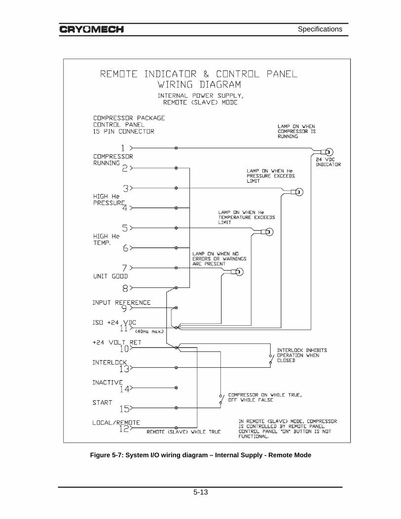
Figure 5-7: System I/O wiring diagram – Internal Supply - Remote Mode
5-13

Specifications
Figure 5-8: System I/O wiring diagram – External Supply - Local Mode
5-14
Specifications
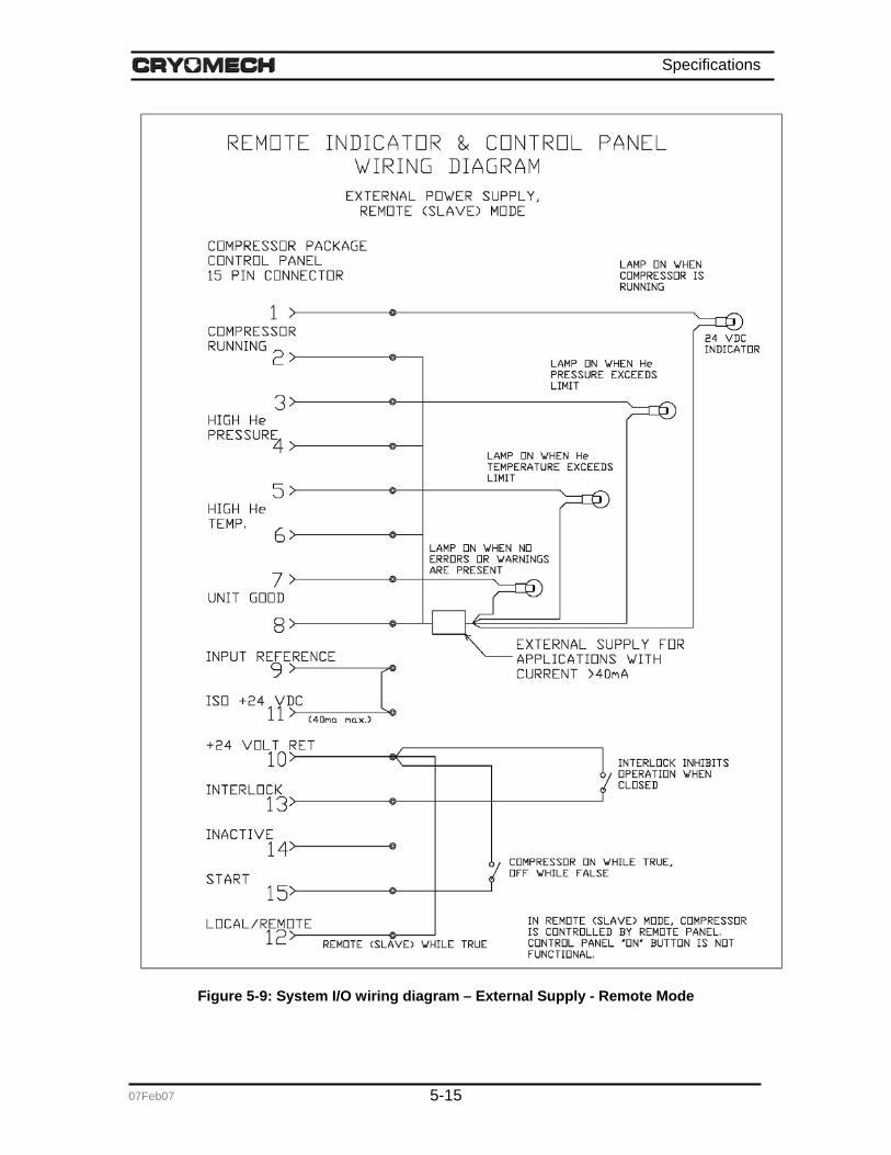
Figure 5-9: System I/O wiring diagram – External Supply - Remote Mode
5-1507Feb07

Section 6
Installation

Installation
Section 6: Installation
6.1 Cold head installation The entire section on the cold head installation should be reviewed before installing the cold head.
CAUTION Failure to follow these installation guidelines could result in voiding the warranty.
CAUTION Because the tubes in the cold head must have very thin walls for cryogenic performance, extreme care must be taken when handling the cold head. Take special care to not dent or bend the tube assemblies. The warranty will not cover dented or bent tubes.
CAUTION Operating the cold head in a magnetic field of greater than 500 gauss will void the warranty.
6.1.1 Inspect the cold head
Motor Electrical Feed Through
Aeroquip Connector Base Plate
Heat Exchanger
Figure 6-1: Representative schematic of a cold head
6-1

Installation
1) Inspect the mounting surface of the base plate for any scratches in the sealing area. Scratches or dents on the sealing surface will cause a leak from the ambient into the vacuum vessel.
2) Inspect the interface surfaces of the copper heat exchanger for scratches or dents before attaching anything to it. Scratches or dents will prevent good thermal contact between the heat exchanger and the object(s) attached to it.
Please notify Cryomech if scratches or dents are observed on any of the above-mentioned surfaces.
3) Make certain the flat gaskets are present and properly seated in the ends of the Aeroquip® connectors.
6.1.2 Initial preparation of the cold head
1) Clean the mating surfaces of the base plate and heat exchanger(s) with isopropyl alcohol.
2) Apply a small amount of vacuum grease to the mating flange O-ring (not supplied) and insert in the O-ring groove.
3) Join the mating flange of the vacuum chamber onto the cold head. Secure the flange to the base plate with the proper number of screws. Be certain to tighten the screws evenly around the mating surface.
CAUTION Because the tubes in the cold head must have very thin walls for cryogenic performance, extreme care must be taken when handling the cold head. Take special care to not dent or bend the tube assemblies. The warranty will not cover dented or bent tubes.
4) Prepare the desired cold mating surface(s) and, applying a small amount of
Apiezon® N grease or pure Indium foil on all cold mating surfaces, secure to the heat exchanger(s) using brass screws.
CAUTION Do not apply heat directly to the cold head (e.g. soldering anything to the cold head heat exchanger(s)). Doing so will destroy the cold head and void the warranty. The warranty will not cover heating of the cold head over 325K (125ºF, 52ºC).
CAUTION In some applications, heavy components must be mounted to the cold surface(s). With the cold head oriented vertically, the maximum allowable load cannot exceed the value specified in Section 5. If your application requires a heavier load or an orientation other than vertical with a load, please contact Cryomech. An excessive load on the cold head can damage the tubes. This type of damage is not covered under the warranty.
6-2

Installation
CAUTION If the bolt pattern on the heat exchanger(s) needs to be changed, you must consult Cryomech first to learn how to prevent damage to the cold head. Holes drilled without prior approval from Cryomech will void the warranty.
6.1.3
6.1.4
6.1.5
Optimal installation of temperature sensors (optional)
If the application requires the use of temperature sensors to monitor performance, there are three major areas that are critical to proper monitoring:
1) Proper mounting of the sensor(s) on the heat exchanger(s).
2) Proper joining of sensor lead wires and connecting wires.
3) Thermal anchoring of the lead wires to the heat exchanger(s).
Many reports of poor performance are traced back to problems in one of the three above areas.
Please refer to the Technical Manual if you need more specific details on installation of the sensors.
Installation of heaters (optional)
If the application requires the use of heaters to optimize performance, there are three major concerns that are critical to optimum performance:
1) Proper mounting of the heater(s) on the heat exchanger(s).
2) Proper joining of heater lead wires and connecting wires.
3) Thermal anchoring of the lead wires to the heat exchanger(s).
Many reports of poor performance are traced back to one of the three above areas.
Please refer to the Technical Manual if you need more specific details on installation of heaters.
Mounting the radiation shield (optional)
1) Clean the radiation shield with isopropyl alcohol.
2) Apply a small amount of Apiezon® N grease or pure Indium foil on the shield mating surface. Attach the radiation shield with brass screws. Tighten it evenly to the first stage heat exchanger.
6.2 Compressor installation The entire section on compressor installation should be reviewed before installing the compressor package.
CAUTION Failure to follow these installation guidelines could result in voiding the warranty.
6-3

Installation
6.2.1 Prepare the compressor package location
• Confirm that the physical space containing the compressor package has an ambient temperature in the range 45 to 100°F (7 to 38°C).
• Place the compressor package in a level position. For the compressor package to operate under optimal conditions, it must be oriented within 5° of being level.
WARNING The compressor package must be positioned to provide easy access to the front-panel mounted circuit breaker.
• Position the compressor package so there is sufficient space around it for changing the adsorber. If the compressor package cannot be moved easily to an open area, leave approximately 2 additional feet (0.6 m) clearance above and to the left and right of it.
• In addition to the above requirements, CP800 Series air cooled models require 2 feet (0.6m) of clearance in front and in back of the unit to ensure proper air flow. CP900 Series air cooled models require 2 feet (0.6m) of clearance around all four sides and 3 feet (1m) of clearance above for proper air flow.
6.2.2 Connect the water lines to the compressor
CAUTION Cooling water must meet the requirements in Section 5. If water that does not meet the cooling water specifications in Section 5 is introduced into the system, even for cleaning purposes, it will void the warranty.
CAUTION Do not apply heat to the cooling water inlet and outlet connectors located on the front panel of the compressor.
1) Make sure that the cooling water supply is turned OFF.
2) Apply Teflon tape or pipe sealant to the threads on the male pipe thread (MPT) fittings that you provide to connect to the compressor’s cooling water inlet connection and the cooling water outlet connection.
o CP900 and CP800 Series Compressors require 1/4 MPT (1/4” Male National Pipe Thread) fittings.
o CP2800 and CP1000 Series Compressors require 3/8 MPT (3/8” Male National Pipe Thread) fittings.
3) Attach the fittings to the compressor’s cooling water inlet and outlet connections. Turning the fitting clockwise, first hand-tighten the connection. Use a wrench to keep the compressor’s cooling water connections from turning, and use another wrench to tighten fittings until snug.
6-4
Installation
4) Attach the supply water line to the Cooling Water IN fitting and the return water line to the Cooling Water OUT fitting.
5) Turn the cooling water supply ON and check for leaks.
6) Make certain the cooling water flow rate and inlet temperature meets the requirements in Section 5.
6.2.3 Connect the compressor package to the main power
CAUTION A voltage deviation of more than 10% above or below the voltage rating can cause compressor motor overheating and possible failure. Indications of operation outside that voltage range will void the compressor warranty.
1) The system MUST be connected to a dedicated circuit breaker. The breaker must be
mounted near the compressor package, within easy reach of the operator, and must be marked as the disconnecting device for the system. Specifications for circuit breakers vary according to the system’s operating voltage. See the electrical specification tables in Appendix A for more information.
2) The compressor package comes with a main power cord attached. Assure that the length of the cord is sufficient to safely connect to the power source. If the cord is not sufficiently long, adjust the location of the compressor package.
WARNING Be sure to follow all local electrical codes and guidelines.
3) Make sure that the dedicated circuit breaker is turned OFF.
4) The ground (or earth) wire in the power cord is either green (60 Hz systems) or green/yellow stripe (50 Hz systems). Connect the ground wire in the power cord to the ground (or earth) connector in the breaker panel, making sure to tighten the wire into the connector securely. It is important not to disable this wire.
5) Connect the remaining hot wires in the power cord to the corresponding lugs on the dedicated breaker in the breaker panel, making sure to tighten the connector securely. The order of the wires is not important for single phase, CP800 Series compressor packages. For 3 phase compressor packages, the order of the wires is not important at this time - correct order will be determined in Section 7.
WARNING One lead of the compressor package is grounded. Never bypass this ground or attach the compressor package to an ungrounded circuit. A dangerous electrical hazard will develop.
6-5

Installation
6.2.4 Connect the helium flex lines to the cold head and the compressor package
CAUTION Follow the procedure carefully when connecting and disconnecting the helium flex lines. Failure to follow the procedure can cause accidental coupling disassembly, destruction of the sealing O-ring, and helium loss.
CAUTION Do not allow the flex lines to come into contact with corrosives or any type of commercial cleaning agent. Helium leaks caused by exposure to corrosives or commercial cleaning agents will not be covered under warranty.
CAUTION Do not bend the flex lines to less than 10 inch (25 cm) radius or permanent damage may occur. This type of damage is not covered under the warranty.
1) Remove all dust caps and plugs from the helium flex lines, compressor package and cold head and place in tool kit. Save dust caps and plugs for future use.
2) Make certain the flat gaskets are present and properly seated in the compressor’s and cold head’s male Aeroquip® fittings.
3) With a dry, clean lint-free cloth remove any visible particles from the ends of all of the Aeroquip® couplings.
IMPORTANT On some models, the high-pressure and low-pressure helium flex lines are not interchangeable due to the size of the Aeroquip® couplings attached to the ends of the flex lines. Before connecting the flex lines to the components, check the Aeroquip® couplings on the ends of lines to make certain they match the Aeroquip® couplings of the components.
4) With the wrenches supplied in the tool kit, connect a helium flex line to the low-pressure port on the compressor package front panel. See Figure 6-3. The low-pressure port is marked “Low.” Tighten the connector until a positive stop is felt. When attaching the Aeroquip® to the mating connector, make sure the threads are in alignment before you tighten the connector.
6-6

Installation
IMPORTANT When connecting or disconnecting the flex lines, Cryomech recommends using a small amount of Teflon spray lubricant. A can of lubricant is included with each system. Before using the lubricant, you must read the instructions for its use. Instructions are packaged with the lubricant and included in Appendix B of this manual.
Turn this wrench Hold this wrench
Figure 6-3: Connecting the flex lines to a compressor package
5) Connect the other end of the helium flex line to the low-pressure port on the cold head. The low-pressure port is marked “Low.” Tighten the connector until a positive stop is felt.
Turn this wrench Hold this wrench
Figure 6-4: Connecting the low-pressure flex line to the low-pressure port on a cold head
6) With the same wrenches, connect the other helium flex line to the high-pressure port on the compressor package front panel. The high-pressure port is marked “HIGH”. Tighten the connector until a positive stop is felt.
7) Connect the other end of the helium flex line to the high-pressure port on the cold head. The high-pressure port is marked “HIGH”. Tighten the connector until a positive stop is felt.
6-7

Installation
WARNING Never remove the Aeroquip® couplings from the helium flex lines without first relieving the helium charge in the line to acceptable levels. The pressure in the hose can blow off the coupling with sufficient force to cause injury.
6.2.5
6.2.6
Connect the cold head motor cord
1) Note that the female plugs attached to each end of the cold head motor cord are unique for both the compressor and the cold head.
2) Assure that the cold head motor cord is sufficiently long to reach the cold head. If the cord length is not sufficient to reach the cold head, adjust the location of the compressor package or the cold head.
3) To connect the cold head motor cord to the cold head, make sure that the alignment pins on the receptacle correspond to the alignment grooves on the plug. Turn the plug sleeve clockwise while pushing the plug into the receptacle. The plug is designed to “click and lock” when assembly is completed.
4) To connect the cold head motor cord to the compressor, align the pins on the plug with the grooves on the compressor’s connector. Push the plug onto the connector and turn the locking ring clockwise until snug.
Remove excess helium from the compressor package
IMPORTANT The system is shipped from the factory with excess helium in order to allow for some loss when assembling system components. Complete this step ONLY if the actual system pressure exceeds the pressure indicated in Step 1, below.
1) Observe both the low and high pressure gauges located on the front panel of the compressor package and determine which gauge has the lower reading. If the system helium pressure shown on the lowest reading gauge EXCEEDS the pressure specified in Appendix A follow the procedures in this step. Otherwise, skip this step and go to Section 7.
2) Assuming pressures EXCEED those indicated in Step 1, above, first make sure that the service valve (located on the front panel) is CLOSED (turned fully clockwise).
3) Attach the ¼" service Aeroquip® coupling to the service access.
4) Turning the service valve counter-clockwise, open the valve SLOWLY. Do not vent more than 5 PSIG (.34 bar) of gas per minute.
5) Observe the gauge with the lower reading. Once the gauge reaches the system helium pressure indicated in Step 1, close the service valve by turning clockwise and remove the service Aeroquip® from the service access.
6-808Feb07

Section 7
Operation

Operation
Section 7: Operation
7.1 Starting the system
7.1.1 Checks before operating
1) Check the system pressure - the gauges should read the pressure specified in Section 5.
o If the pressure is too high, vent some of the helium following the instructions in Section 6.
o If the pressure is too low, add helium following the instructions in Section 8.
2) Make sure the cold head motor cord is connected to both the compressor and the cold head.
3) Make sure all Aeroquip® couplings are securely fastened and the helium flex lines are oriented correctly.
4) Make sure the input power meets the specifications on the identification label.
CAUTION A voltage deviation of more than 10% above or below the voltage rating can cause compressor motor overheating and possible failure. Indications of voltage operation outside that range will void the compressor warranty.
5) Make sure the flow rate and temperature range of the cooling water meet the
requirements specified in Section 5.
6) Check that the dedicated circuit breaker is on.
CAUTION Operating the cold head in a magnetic field of greater than 500 gauss will void the warranty.
7.1.2 Startup procedure
1) Switch on the compressor package power at the MAIN circuit breaker.
2) Switch on the power to the compressor controls by switching on the POWER circuit breaker. The green ON light above the circuit breaker and the yellow Compressor Off light will both illuminate. A series of beeps will be heard and the front panel display will initially show the compressor model number, date and time. After a few seconds the display will read Compressor Off and the number of hours on the system.
3) The compressor may be started by pushing the green “Compressor On” button, and stopped by pushing the black “Compressor Off” button. The compressor controller does a power check for five seconds after the control power is switched on. During this check the compressor will not start if the Compressor On button is pushed. After the power check has been successfully completed, the compressor will start. There is
7-1

Operation
also a 10 second time delay built in to allow pressure equalization in the event that the Compressor On button is pushed immediately after the Compressor Off button is pushed.
4) If the front panel display indicates “PWR PHASE ORDER BAD” after pushing the “Compressor On” button, follow the instructions below.
5) Perform the following steps to correct the phase error in the compressor package:
a. Switch off the two circuit breakers on the front panel of the compressor package.
b. Turn off the dedicated circuit breaker to disconnect the system from power at the source (to prevent electrical shock).
c. Examine the power cord and wire colors at the panel circuit breaker. Re-wire the input to the compressor by switching any 2 of the 3 input power wires.
d. Energize the breakers and press the “Compressor On” button. The compressor package should now operate properly.
7.2 Normal operation behavior
7.2.1 Normal pressures
On start up a pressure differential should be noticed immediately between the high and low pressure gauges. This differential will decrease as the cold head cools down.
The typical pressure differential is approximately 220 to 250 PSI (15.2 to 17.2 bar) with a 5 to 10 PSI (.34 to .7 bar) bounce on the pressure gauge needles.
Actual operating pressures at various cold head temperatures are recorded on the Cold Head Performance Table that is included with the cold head.
7.2.2 Normal sounds
When operating properly, the cryorefrigerator will emit a rhythmic squeak or chirp. This noise is an indication of the proper flow of helium gas within the system.
7.2.3 Cool down time
Refer to Appendix A for the cool down time of an unloaded cold head with no additional mass on the heat exchanger(s). If the cold head is exposed to a heat load or additional mass is attached, the cool down time will increase.
7.2.4 Normal temperatures
Refer to Appendix A for the minimum no-load temperature of the cold head.
This temperature will vary depending on the quality of the vacuum, the quality of the super-insulation, and the heat load brought in by the instrumentation leads.
The Cold Head Performance Table includes additional temperature data for the cold head.
7.3 Use of the display panel Status and error messages will be shown on the display screen. The status messages, error messages, and set points at which error conditions will occur are listed in Section 7.7.
7-2

Operation
The screen normally shown on the display is referred to as the run-time screen. The messages described in Section 7.7 are displayed on the top line of the run-time screen. The bottom line displays the number of hours the compressor has run.
The Service/Return button is used to switch from the run-time display to the top level of the menu - Monitor Sensors / Error Log / Event Log / User Settings / Service / Comm Settings. See Appendix A - CMAS Menu System - for the detailed depiction of the menu system.
The Service/Return button can also be used to return to the run-time screen from any part of the menu.
The INC and DEC buttons are used to navigate back and forth along the top level of the menu. The Select button is used to navigate down each menu, and the Cancel button is used to move back up.
7.4 Shutdown procedure Press the black “Compressor Off” button on the front panel of the compressor package. This will switch off the compressor system. Switch off the front-panel mounted circuit breakers to shut down the entire system.
7.5 Recommended routine procedures
INFORMATION It is helpful to monitor the cryorefrigerator daily in order to detect changes in performance early. These changes can signify degradation in performance that could result from the beginning of a problem that requires attention.
Cryomech recommends keeping regular logs of key measurements at intervals that make sense for the way you use your system.
7.5.1 High and low pressure
Changes in the high and low pressure readings on the compressor package’s gauges are used for diagnosing several different types of problem. It is important to know whether changes are sudden or gradual and to know how the high and low pressures are changing relative to each other.
The high and low pressures should be monitored daily.
Cryomech recommends that you maintain a regular record, at intervals that make sense for the way you use your system, of the high and low pressure readings. The RS232/488 port can be used to remotely monitor and record the pressure data.
7.5.2 Cold head temperature
Temperature changes are the other key diagnostic.
If a temperature sensor is attached to the cold head’s heat exchanger(s), Cryomech strongly recommends that you monitor the temperature(s) daily.
Cryomech also recommends that you keep a regular record of the temperature(s) at intervals that make sense for the way you use your system.
7-3

Operation
7.5.3 Cooling water input and output
If possible, Cryomech recommends keeping a regular record of the input and output cooling water temperatures and of the cooling water flow rate. The RS232/488 port can be used to remotely monitor and record the water temperature data.
7.6 Disassembling the system for transport or storage Use the following steps to prepare a Cryomech cryorefrigerator for eventual transport or storage.
1) Make sure that the display on the front panel indicates that the compressor system is OFF.
2) Disconnect the power to the system by switching the front panel breakers to the OFF position
3) Disconnect the main power to the system by switching the dedicated circuit breaker to the OFF position.
4) Disconnect the power cord from the external breaker panel. Coil up the power cord in preparation for transport or storage.
5) Disconnect the cold head motor cord from the cold head and from the compressor. Coil the cold head motor cord in preparation for transport or storage.
6) Turn off the water supply at the source.
7) Using two wrenches disconnect the supply and return water lines from the inlet and outlet fittings by turning the fittings counter-clockwise until they are released from the fittings. Store the connectors for transport or storage.
8) Drain the water from the compressor package. Blow remaining water out with compressed air.
IMPORTANT 4K PULSE TUBE SYSTEMS ONLY
Do not continue with the remaining steps until the cold head temperature has risen above 150K. If the cold head is disconnected from the system while below 150K, helium will expand within the cold head as it warms, escape through the pressure relief valve and require the user to recharge the system with helium before it would again operate properly.
9) Using the wrenches supplied in the tool kit, disconnect the high and low pressure flex lines from the compressor package by turning the Aeroquips® counter-clockwise with one wrench while holding the other wrench to prevent the flex line from twisting. See Figure 7-1.
IMPORTANT When connecting or disconnecting the flex lines, Cryomech recommends using a small amount of Teflon spray lubricant. A can of lubricant is included with each system. Before using the lubricant, you must read the instructions for its use. Instructions are packaged with the lubricant and included in the Appendix of this manual.
7-4

Operation
Turn this wrench
Hold this wrench
Figure 7-1: Disconnecting flex lines from a compressor package
10) Disconnect the Aeroquips® on the high and low pressure fittings on the cold head by turning the flexible line’s Aeroquip® counter-clockwise with one wrench while holding the cold head’s Aeroquip® with the other wrench. See Figure 7-2.
Turn this wrench Hold this wrench to prevent the cold head’s Aeroquip from loosening
Figure 7-2: Disconnecting flex lines from a cold head
11) Install the dust plugs (that originally came with the system and are stored in the tool kit) on the female Aeroquip® couplings attached to the helium flex lines.
12) Install the dust caps on the male Aeroquip® fittings located on the compressor package and the cold head.
13) If necessary, disconnect the cold head from its mounting surface, taking care not to damage any components. Once disconnected, place the cold head in the original packaging container.
WARNING Do not touch the cold end of the cold head until it has warmed to room temperature. If there is frost on the cold head, it is too cold to touch.
7-5
Operation
14) Recoil the helium flex lines and prepare for transport or storage.
15) Assure that all components are stored in appropriate containers and location.
7-6

Operation
7.7 Troubleshooting
7.7.1 System will not start
SYMPTOM System will not start.
POSSIBLE CAUSE
1) No power supplied to the compressor package. 2) Circuit breakers off. 3) “Compressor Error” message displayed on display screen.
REMEDY 1) Check the power supply to the system and verify that it meets the requirements outlined in Section 5.
2) Make certain both circuit breakers, located on the front panel of the compressor package, are on.
3) Refer to Section 7.7.5 for error message diagnostics.
7.7.2 System starts, no pressure fluctuation
SYMPTOM System starts, no bounce in the pressure gauges, no refrigeration.
POSSIBLE CAUSE
1) Cold head motor cord not connected to the cold head and/or to the compressor package.
2) Aeroquip® connector(s) not completely tightened. 3) High and low pressure helium flex lines reversed.
REMEDY 1) Turn off the compressor and connect the cold head motor cord to the cold head and/or to the compressor package.
2) Tighten all Aeroquip® connectors. 3) Verify that one of the helium flex lines connects the high pressure
port on the compressor package to the high pressure port on the cold head and that the other helium flex line connects the low pressure ports.
7-7
Operation
7.7.3 System has shut itself down
SYMPTOM System has shut itself down.
POSSIBLE CAUSE
1) Circuit breaker tripped. 2) Interruption of the power supply to the compressor package. 3) “Compressor Error” message displayed on front panel screen.
REMEDY 1) Reset the circuit breaker on the front panel of the compressor package.
2) Check the power supply to the system and verify that it meets the requirements outlined in Section 5.
3) Refer to Section 7.7.5 for error message diagnostics.
7.7.4 Run time display screen description
Run time messages are displayed on the top line of the display screen. The number of hours the system has operated is displayed on the bottom line.
Top line message on the display screen Message description
“COMPRESSOR OFF” Front panel or remote interface turned off compressor. All is well.
“COMPRESSOR ON” Compressor is running. All is well.
“STARTING…WAIT X” (X is a number, counting down. When X is zero compressor will start)
Compressor On request received, and compressor will start within 10 seconds unless an error occurs or a stop request is received. This message will show when the compressor has not been off for more than 10 seconds and a start request is received. This state allows the pressure to balance.
“WAITING FOR POWER”
Compressor is waiting for good power. Will be displayed for a short time while the power tracking state machine is checking the line power, which takes 5 seconds minimum. In this state, WHEN POWER COMES BACK, THE COMPRESSOR WILL START.
“COMPRESSOR ERROR”
An error has occurred. The error will be displayed on the second line. If more than one error is lodged, the highest priority error will be displayed on screen. See below for error display and description.
“ERR HOLD…WAIT x” (x is a number, counting down, in seconds. When x is zero compressor will start)
Compressor On request received and compressor will start in x seconds unless an error occurs or a stop request is received. This message will show when the compressor has encountered certain errors that require a minimum off time.
“CALL FACTORY”
The compressor has entered a locked-out state due to experiencing 6 errors within one hour. The compressor cannot be restarted until a special code is entered. You must contact Cryomech to
7-8

Operation
obtain this code. Have the CPU serial number and compressor hours ready (see Service menu). The lockout contributors are noted in Section 7.6.5.
“ERROR! NO MESSAGE!” This message should never be seen. It indicates the compressor is in a state with no description available.
7.7.5 Error diagnostics on display screen
Errors will cause the compressor system to stop. Errors are displayed on the bottom line of the display screen. If more than one of the errors below is present, only the highest priority one will be displayed. The table lists errors from highest to lowest priority. If the error is a lockout contributor, it will be noted in the Explanation column. When an error has occurred, the Compressor On indicator light will blink and the panel will emit a beeping sound. To stop the beeping sound, press the Compressor Off Button. Once the error condition has cleared, the compressor can be restarted by pressing the Compressor On Button. The light will stop blinking once the compressor has restarted. If the error condition still exists the compressor will not restart and the light will continue to blink.
Error Message Explanation
“FATAL ERROR: I2C” This occurs if the I2C bus fails or a part on the I2C bus fails. Cycle power. If the condition persists, contact factory. Lockout contributor.
“FATAL ERROR: 5V HIGH” The 5V power as measured by the system exceeds the limit of 5.25 volts. Contact factory. Lockout contributor.
“FATAL ERROR: 5V LOW”
The 5V power as measured by the system is below the limit of 4.75 volts. May be caused by a shorted sensor. Contact factory. Lockout contributor.
“SYSTEM LOCKOUT 1”
The compressor is in lockout mode due to more than 6 errors within one hour; the compressor cannot be started until a code is entered. Contact factory. Lockout contributor.
“PWR PHASE ORDER BAD” The order of the phase power is wrong. Re-wire the input to the compressor by switching any 2 of the 3 input power wires.
“REMOTE INTERLOCK 1” Occurs when the “remote interlock” parameter is enabled (default) and the digital remote interlock line is TRUE.
“REMOTE INTERLOCK 2” General purpose user interlock can only be set via the computer interface.
“HIGH He PRESSURE” This occurs when high side helium pressure is too high. Release helium from the system. Lockout contributor.
“LOW WATER FLOW”
This occurs when the output water temperature exceeds a threshold. Check flow rate and inlet temperature of cooling water. Lockout contributor.
“HIGH He GAS TEMP” This occurs when the helium gas temperature exceeds a threshold. Probable cause is insufficient oil in the top sump of the compressor
7-9

Operation
module. Check oil level in top sump sight glass when system is operating. Lockout contributor.
“LOW He PRES” This occurs when the helium gas pressure is below the threshold. Add helium to the system. Lockout contributor.
“COMP MOTOR CURRENT”
This occurs when the compressor module motor current is below threshold while the motor is requested running. Can be caused by an overheated compressor module. Lockout contributor.
“HIGH OIL TEMP”
This occurs when the compressor oil temperature exceeds a threshold. Check flow rate and inlet temperature of cooling water. Lockout contributor.
“LOW VOLTS ON MAINS”
Compressor wants to be on but cannot run because one or more of the mains power “legs” has failed (phase loss or low voltage). When the power error has been corrected, THE COMPRESSOR WILL START!
7.7.6 Warning diagnostics on display screen
Warnings do not cause the compressor to stop and do not prevent the compressor from starting. Warnings are displayed on the bottom line of the display screen. If more than one of the warnings below is present, only the highest priority one will be displayed. The table lists warnings from highest to lowest priority.
Warning Message Explanation
“*WARN:NO HI PSI SENS”
This occurs when the high side helium pressure sensor has published a reading that is out of the range of the sensor. Indicates a bad sensor or shorted wiring.
“*WARN:NO LOW PSI SNS”
This occurs when the low side helium pressure sensor has published a reading that is out of the range of the sensor. Indicates a bad sensor or shorted wiring.
“*WARN:HIGH DP” The DP (Delta Pressure) has exceeded the threshold.
“*WARN:STALL DETECTED” The compressor has detected no cold head activity, the cold head has stalled or been disconnected.
“*WARN:NO IN WTR SENS”
This occurs when the input water temperature sensor has published a reading that is out of the range of the sensor. Indicates a bad sensor or shorted wiring.
“*WARN: IN WTR TEMP HI” The temperature of the input water has exceeded the threshold.
“*WARN:NO OUT WTR SNS”
This occurs when the output water temperature sensor has published a reading that is out of the range of the sensor. Indicates a bad sensor or shorted wiring.
“*WARN:NO He TMP SENS” This occurs when the helium temperature sensor has published a reading that is out of the range of the sensor. Indicates a bad sensor or shorted
7-10
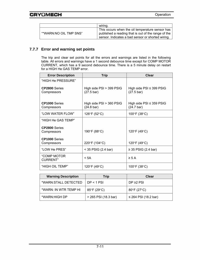
Operation
wiring.
“*WARN:NO OIL TMP SNS” This occurs when the oil temperature sensor has published a reading that is out of the range of the sensor. Indicates a bad sensor or shorted wiring.
7.7.7 Error and warning set points
The trip and clear set points for all the errors and warnings are listed in the following table. All errors and warnings have a 1 second debounce time except for COMP MOTOR CURRENT, which has a 9 second debounce time. There is a 5 minute delay on restart for a HIGH He GAS TEMP error.
Error Description Trip Clear “HIGH He PRESSURE” CP2800 Series Compressors CP1000 Series Compressors
High side PSI > 399 PSIG (27.5 bar) High side PSI > 360 PSIG (24.8 bar)
High side PSI ≤ 399 PSIG (27.5 bar) High side PSI ≤ 359 PSIG (24.7 bar)
“LOW WATER FLOW” 126°F (52°C) 100°F (38°C)
“HIGH He GAS TEMP” CP2800 Series Compressors CP1000 Series Compressors
190°F (88°C) 220°F (104°C)
120°F (49°C) 120°F (49°C)
“LOW He PRES” < 35 PSIG (2.4 bar) ≥ 35 PSIG (2.4 bar)
“COMP MOTOR CURRENT” < 5A ≥ 5 A
“HIGH OIL TEMP” 120°F (49°C) 100°F (38°C)
Warning Description Trip Clear
*WARN:STALL DETECTED DP < 1 PSI DP ≥2 PSI
*WARN: IN WTR TEMP HI 85°F (29°C) 80°F (27°C)
*WARN:HIGH DP > 265 PSI (18.3 bar) ≤ 264 PSI (18.2 bar)
7-11

Operation
7.8 Contact Cryomech with Questions It is hoped that the Operations Section of this manual has helped you to obtain satisfactory results in the use of your cryorefrigerator. While the information offered should facilitate set up and operation, you may have a special situation that requires further considerations. If after reading the Operations Section, you still have questions, contact Cryomech for further information.
7.8.1 Contact Information Cryomech, Inc. 113 Falso Drive Syracuse, NY 13211
Phone: (315) 455-2555 Fax: (315) 455-2544
Email: [email protected]
Website: www.cryomech.com
7-1205Feb07

Section 8
Routine Maintenance

Routine Maintenance
Section 8: Routine Maintenance
8.1 Introduction This section contains basic, essential maintenance information. For more detailed information, consult the technical manual, which can be obtained by contacting Cryomech.
8.2 Maintenance schedule Maintenance Frequency Comment
Replace adsorber Every 20,000 hours See Section 8.4 Vent helium gas As required See Section 8.5 Charge helium gas As required See Section 8.6
8.3 Cold head
CAUTION The cold head contains no user-serviceable parts. Attempting to disassemble the cold head will void the warranty. CONTACT CRYOMECH IF THE COLD HEAD NEEDS TO BE RETURNED FOR SERVICING.
8.4 Replace the adsorber Required tools:
Quantity Description Comment 1 1” Open end wrench For Aeroquip® coupling 1 1-1/8” Open end wrench For Aeroquip® coupling 1 1-3/16" Open end wrench For Aeroquip® coupling 1 1-3/8" Open end wrench For Aeroquip® coupling 1 1-5/8" Open end wrench For Aeroquip® coupling 1 Slotted screwdriver For hose clamp 1 Phillips head screwdriver For side panel of compressor
CAUTION At no time should the Aeroquip® couplings be removed from the adsorber when replacing the adsorber. Replacement can be completed without relieving system pressure since the adsorber is equipped with Aeroquip® couplings for sealed removal.
8-1

Routine Maintenance
1) Shut down the system.
2) Disconnect both helium flex lines from the compressor.
3) Remove the side panel from the right hand side of the compressor package.
a. Remove the 6 quarter-turn screws that hold the cover on and retain them.
b. Pull the panel away from the compressor package.
4) Using three wrenches disconnect the Aeroquip® coupling between the adsorber and the oil separator as shown in Figure 8-1.
Hold this wrench
Hose clamp
Hold this wrench Turn this wrench
Figure 8-1: Disconnecting the Aeroquip® adsorber
5) Remove the nut holding the high-pressure Aeroquip® coupling to the front panel.
6) Loosen and disconnect the hose clamp that attaches the adsorber to the front panel.
7) Remove the adsorber from the compressor package.
8) Check the Aeroquip® couplings for oil residue. If oil is present, contact Cryomech for further assistance.
9) Remove the lock washer from the top Aeroquip® and install it on the new adsorber.
10) To install the new adsorber, reverse steps 4 through 7.
11) Reconnect both helium flex lines to the compressor.
12) Reattach the cover or side panel to the compressor package.
8.5 Vent excess helium Required tools:
Quantity Description Comment 1 3/4” Open end wrench For Aeroquip® coupling 1 Service Aeroquip® coupling For service access port
8-2

Routine Maintenance
CAUTION Venting more than 5 PSIG (.34 bar) of helium per minute will lead to improper oil migration within the system. If this condition occurs, factory service will be required.
This procedure should only be used to vent small quantities of helium from an overcharged system.
1) Make sure the service valve is closed. See Figure 8-2.
2) Attach the small service Aeroquip® coupling to the service access port.
3) Open the service valve slowly. Do not vent more than 5 PSIG (.34 bar) of helium per minute.
4) After venting the helium, close the service valve and remove the service Aeroquip® from the service access port.
8.6 Recharge helium Required tools and equipment:
Quantity Description Comment 1 3/4” Open end wrench For Aeroquip® coupling 1 Service Aeroquip® coupling For service access port 1 Vacuum/charging station For adding helium
CAUTION When adding helium, the helium must be 99.999% pure. Contamination by other gases will result in the freezing of the contaminant gases in the cold head because their freezing temperature is much higher than that of helium. Contaminants in the helium charge will severely degrade the cold head's function and it will require factory servicing. Contamination of the helium by other gases is a common cause of premature failure and, unless resulting from a system failure, is not covered by the warranty.
This procedure should be performed with the compressor package shut down. Adding helium is possible whether or not the cold head is attached to the compressor package. Both the service access and service valve are connected to the low-pressure manifold of the compressor.
1) Turn the system off.
2) Allow the entire system, both the compressor package and the cold head, to come to room temperature.
3) Use only high purity helium with a minimum purity of 99.999%.
4) Check that the helium source and regulator are capable of pressurizing to the desired pressure.
5) Make sure the service valve is closed.
6) Attach the service Aeroquip® coupling to the service access port.
8-3

Routine Maintenance
Charging hose
Service Valve
Service Aeroquip® Coupling
Figure 8-2: Service valve and access port
7) Attach a charging line from the service Aeroquip® to a typical vacuum/charging system as shown in Figure 8-3 below.
Figure 8-3: Vacuum/charging system
8) Evacuate to 50 microns.
9) Isolate the vacuum pump and add 50 PSIG (3.4 bar) of helium.
10) Vent the helium and repeat steps 8 to 10.
11) Final evacuation should be to 25 microns.
12) Pressurize the line to the service access with the desired amount of helium pressure.
13) Slowly open the service valve to add helium to the system. The final helium charge in the system is specified in Section 5.
CAUTION No more than 5 PSIG (.34 bar) of gas should be added per minute to prevent internal oil contamination to the system. If such contamination occurs, factory service will be required.
8-4
Routine Maintenance
14) After adding the helium, close the service valve and remove the service Aeroquip® from the service access.
8.7 Cleaning
8.7.1 Compressor package and cold head
The compressor package and cold head require no cleaning other than wiping the outside of each if it becomes dusty or dirty.
CAUTION Never wet either part of the system. Water getting into the system will void the warranty.
8.7.2 Aeroquip® couplings
WARNING Never remove an Aeroquip® coupling from the helium flex lines, cold head or compressor without first relieving the helium charge. The pressure in any of the components can blow off the coupling with sufficient force to cause injury.
If operated in a clean environment, the only parts of the cryorefrigerator system that are likely to require cleaning are the Aeroquip® couplings. The mating surfaces of the Aeroquip® couplings can get particles on them when the helium flex lines are detached from the compressor package and/or the cold head.
If an Aeroquip® coupling needs cleaning:
• Wipe the mating surfaces of the coupling with a dry, lint-free cloth.
• After wiping, blow off the coupling with clean, dry compressed air.
• Solvents should never be used.
• If any grease or oil gets on the Aeroquip® coupling, contact Cryomech.
8-5

Routine Maintenance
8.8 Manufacturer only parts The following parts are available only from Cryomech:
Helium flex lines
The helium flex lines must be handled with care. If they become damaged and need to be replaced, new ones must be obtained from Cryomech and installed using the directions in the installation section of this manual.
Adsorber
The adsorber needs to be replaced after every 20,000 hours of use. See Section 8.4 for instructions on replacing the adsorber.
Cold head
The cold head contains no user-serviceable parts and must be serviced by Cryomech authorized technicians. Attempting to disassemble the cold head will void the warranty. See Section 8.3.
Main power cord
If the power cord becomes damaged, a replacement should be obtained from Cryomech.
Cold head motor cord
If the cold head motor cord becomes damaged, a replacement must be obtained from Cryomech.
8-605Feb07

Appendix A
Specifications Cold Head Drawing CMAS Menu System

Appendix A
Specifications: PT410 with CP2880 Cold head Weight………………………………………………………………….. 43 lb (19.5 kg)
Dimensions…………………………………………………………….. See cold head drawing
Cool down time………………………………………………………... 60 minutes to 4K
Lowest temperature…………………………………………………... 2.8K with no load
Helium static pressure – all components @ 77°F (25°C) 60 Hz System………………………………………………………….. 230 ± 5 PSIG (15.9 ± .34 bar)
50 Hz System…………………………............................................. 17.9 ± .34 bar (260 ± 5 PSIG)
Maximum sound level Water cooled system…………………………………………………. 70 dBA at 1 meter
Flexible lines Standard length….......................................................................... 66 ft (20 m)
Weight (pair)…………………….…………………………………….. 72 lb (32.7 kg)
Electrical specifications
Input Power (kW) Electrical Rating Maximum Steady state
Maximum Current (A)
Dedicated Circuit Breaker (A)
220/230 Volt 60 Hz 9 7.2 27 40
460 VAC 60 Hz 9 7.2 13 25
200/220 Volt 50 Hz 9 7.2 27 40
380/420 VAC 50 Hz 9 7.2 16 25
A-1

Appendix A
Figure A-1: Cold Head Drawing
A-2

Appendix A
Figure A-2: CMAS Menu System
A-306Feb07

Appendix B
Spray Lubricant Instructions
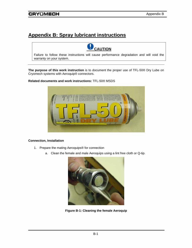
Appendix B
Appendix B: Spray lubricant instructions
CAUTION Failure to follow these instructions will cause performance degradation and will void the warranty on your system.
The purpose of this work instruction is to document the proper use of TFL-50® Dry Lube on Cryomech systems with Aeroquip® connectors. Related documents and work instructions: TFL-50® MSDS
Connection, Installation
1. Prepare the mating Aeroquips® for connection
a. Clean the female and male Aeroquips using a lint free cloth or Q-tip.
Figure B-1: Cleaning the female Aeroquip
B-1

Appendix B
b. Make certain the flat gasket is properly seated in the male Aeroquip®.
Flat Gasket
Figure B-2: Cleaning the male Aeroquip®
2. Thread the female Aeroquip® onto the male by hand, until tight.
Figure B-3: Female to male connection, hand tightened
CAUTION Never apply lubricant to the open ends of the Aeroquips®. Doing so will contaminate the system and void the warranty. Apply lubricant to the Aeroquips® only after they are hand tightened together.
3. Before using this product carefully read and follow the instructions on the can. Only a small amount of TFL-50® should be used. A typical amount is shown in Figure B-4. The spray nozzle should only be depressed for 1 second or less. If a white film appears on the surface, too much lubricant has been applied.
B-2

Appendix B
Figure B-4: Typical amount of lubricant
4. Apply a small amount of TFL-50® to the swivel portion of the female Aeroquip®.
Swivel portion
Figure B-5: Apply lubricant to swivel portion
5. Apply a small amount of TFL-50® to the threaded portion of the male Aeroquip®.
Threaded portion
Figure B-6: Apply lubricant to threaded portion
6. Use wrenches to tighten the Aeroquips® completely (see manual for instructions).
B-3

Appendix B Disassembly
1. Apply a small amount of TFL-50® to the swivel portion of the female Aeroquip® as
shown in Figure B-5.
2. Use wrenches to loosen and remove the Aeroquips® (see manual for instructions).
B-430Jan07