COPYRIGHT DISCLAIMER · CUBO-160 equips with 3 LED indicators which indicate the transmitting...
16
I COPYRIGHT The entire contents of this instruction manual, including any future updates, revisions, and modifications, shall remain the property of AMEC at all times. Unauthorized copies or reproduction of this manual, either in part or whole, in any form of print and electronic media, is prohibited. The contents herein can only be used for the intended purpose of this manual. DISCLAIMER AMEC is devoted to publish and maintain this product manual. As we continue to improve our AIS products to satisfy all customers‟ needs, information in this document is subject to change without notice. AMEC does not make any representations or warranties (implied or otherwise) regarding the accuracy and completeness of this document and shall in no event be liable for any loss of profit or any commercial damage, including but not limited to special, incidental, consequential, or other damage. Contact us at: Technical Support: Sales & Marketing: ALLTEK MARINE ELECTRONICS CO., LTD 7F, No. 605, Ruei-Guang Rd., Neihu, Taipei, Taiwan 114 TEL: +886 2 2627 1599 FAX: +886 2 2627 1600 www.alltekmarine.com (Your Local Dealer/Agent Warranty Stamp) Version 1.1
Transcript of COPYRIGHT DISCLAIMER · CUBO-160 equips with 3 LED indicators which indicate the transmitting...

I
COPYRIGHT
The entire contents of this instruction manual, including any future updates, revisions, and
modifications, shall remain the property of AMEC at all times. Unauthorized copies or
reproduction of this manual, either in part or whole, in any form of print and electronic media, is
prohibited. The contents herein can only be used for the intended purpose of this manual.
DISCLAIMER
AMEC is devoted to publish and maintain this product manual. As we continue to improve our
AIS products to satisfy all customers‟ needs, information in this document is subject to change
without notice. AMEC does not make any representations or warranties (implied or otherwise)
regarding the accuracy and completeness of this document and shall in no event be liable for
any loss of profit or any commercial damage, including but not limited to special, incidental,
consequential, or other damage.
Contact us at:
Technical Support:
Sales & Marketing:
ALLTEK MARINE ELECTRONICS CO., LTD
7F, No. 605, Ruei-Guang Rd., Neihu, Taipei, Taiwan 114
TEL: +886 2 2627 1599
FAX: +886 2 2627 1600
www.alltekmarine.com
(Your Local Dealer/Agent Warranty Stamp)
Version 1.1

II
Warning
The equipment said in this manual must only be used to which it was designed. Improper
operation or installation may cause damage to the equipment or injury to personnel. AMEC will
not incur any liability of equipment damage or personal injury due to improper use or
installation of the equipment. It is strongly recommended to read this manual and the following
safety instructions before proceeding to installation or operation.
SAFETY INSTRUCTIONS
ELECTRICAL SHOCK HAZARD. Do not open the case of the equipment. Only qualified
personnel could work on the interior of the equipment.
WARNING
TURN OFF THE POWER IMMEDIATELY IF WATER LEAKS INTO THE EQUIPMENT OR OBJECT DROPS INTO THE EQUIPMENT. Continue operating the equipment could cause electrical shock or fire. Contact your nearest distributor for service.
DO NOT DISASSEMBLE OR MODIFY THE EQUIPMENT. Improper disassemble or modification could cause electrical shocks, fire, or personal injury.
WARNING
DO NOT PLACE ANY LIQUID-FILLED CONTAINER ON TOP OF THE EQUIPMENT. Electrical shocks could be resulted if the device is contaminated with liquid.
TURN OFF THE POWER IMMEDIATELY IF THE EQUIPMENT IS EMMITTING SMOKE OR FIRE. Continue operating the equipment could cause electrical shock or fire. Contact your nearest distributor for service.
EVEN THOUGH THE EQUIPMENT IS WATERPROOF, PLEASE AVOID DIRECT CONTACT WITH RAIN OR SPLASHING WATER. Electrical shock or fire could be resulted if water leaks into the equipment.
AVOID OPERATING THE EQUIPMENT WITH WET HANDS. Electrical shocks could be resulted if operating with wet hands.
DO NOT CUT, SHORTEN OR LENGTHEN THE SUPPLIED CABLES BY AN APPROPRIATE SUPPLIER. Improper change of cable length and connector could cause failure of transmitting signal.

III
ABOUT THIS MANUAL
Congratulations on the purchase of your new CUBO-160 VHF-AIS Transponder Antenna
Splitter. CUBO-160 is strictly tested to meet the rigorous demands of the marine environment.
Unless improper use, installation, or maintenance, the equipment should function properly at its
optimum.
The installation instructions contained in this manual is applied only to CUBO-160. While the
owner or the crew can perform most of the installation, your local agent/dealer can do a final
commissioning if desired or required. AMEC and the authorized local agent/dealer will not bear
any responsibilities of damages resulted from improper installation by any unauthorized
agent/dealer.
We thank you for choosing our product and we wish you a bon voyage.

IV
Table of Contents
I. COPY RIGHT & DISCLAIMER
II. WARNING & SAFETY INSTRUCTION
III. ABOUT THIS MAUNAL
1. CUBO-160 INTRODUCTION ............................................................................ 1
2. INSTALLATION ................................................................................................ 1
2.1 Items in the Package ................................................................................................................. 2
2.2 Installation Procedure ............................................................................................................... 3
2.2.1 Mounting ........................................................................................................................... 3
2.2.2 Connection Port Definition ........................................................................................... 3
2.2.3 Connecting ....................................................................................................................... 4
3. OPERATION ..................................................................................................... 5
3.1 LED Indicators ............................................................................................................................ 5
3.2 Notice of operation .................................................................................................................... 5
4. TROUBLESHOOTING ...................................................................................... 6
5. APPENDIX ........................................................................................................ 7
5.1 Product Specifications ............................................................................................................. 7
5.2 Dimensions .................................................................................................................................. 8
7. DECLARATION OF CONFORMITY ................................................................ 12
1
1. CUBO-160 INTRODUCTION
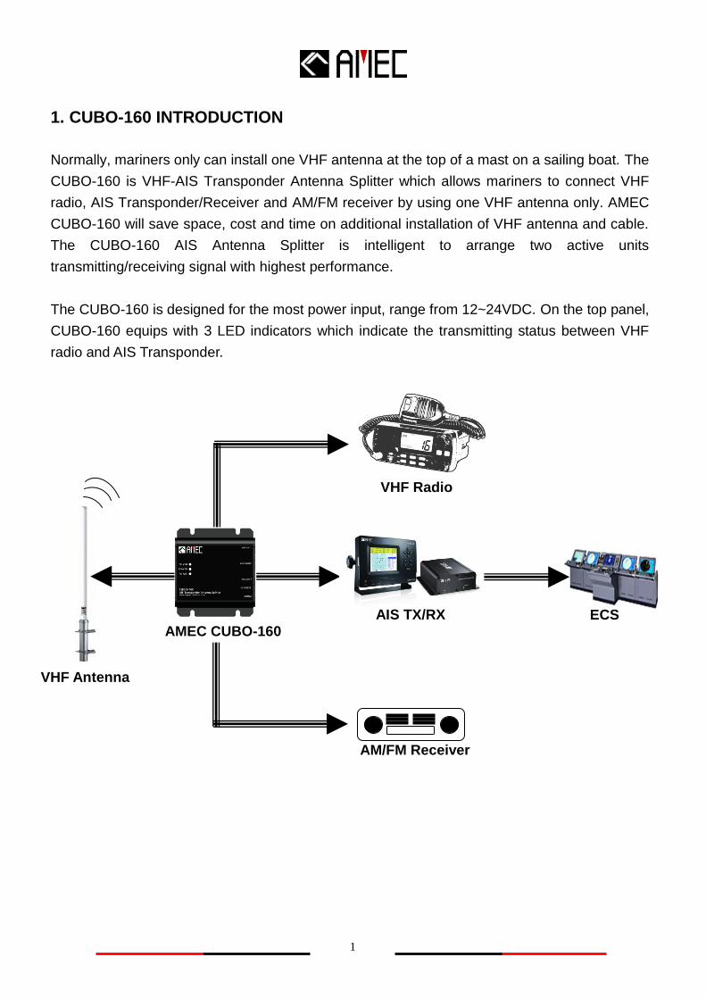
Normally, mariners only can install one VHF antenna at the top of a mast on a sailing boat. The
CUBO-160 is VHF-AIS Transponder Antenna Splitter which allows mariners to connect VHF
radio, AIS Transponder/Receiver and AM/FM receiver by using one VHF antenna only. AMEC
CUBO-160 will save space, cost and time on additional installation of VHF antenna and cable.
The CUBO-160 AIS Antenna Splitter is intelligent to arrange two active units
transmitting/receiving signal with highest performance.
The CUBO-160 is designed for the most power input, range from 12~24VDC. On the top panel,
CUBO-160 equips with 3 LED indicators which indicate the transmitting status between VHF
radio and AIS Transponder.
AMEC CUBO-160
VHF Antenna
AM/FM Receiver
VHF Radio
AIS TX/RX ECS

2
2. INSTALLATION
2.1 Items in the Package
The CUBO-160 is typically delivered with standard package as shown in Table 2-1. It is also
illustrated in Figure 2-1.
Table 2-1 Standard equipment list
No. Description Qty
1 CUBO-160 VHF Antenna Splitter main unit 1
2 Manual (CD-ROM) 1
3 Installation
Kit
Power Cable, 1.5m, AWG 18 1
VHF Radio Connector Cable 1
AIS Transponder Connector Cable 1
UHF Plug – BNC Jack Adaptor 1
M4×20 Screw 4
Figure 2-1 Standard Package
1. CUBO-160 x1
2. Power Cable x1
3. VHF Radio Connector Cable x1
4. AIS Transponder Connector Cable x1
5. UHF Plug – BNC Jack Adaptor x1
6. M4x20 Screw x4
1. 3.
2.
5.
4.
6.

3
2.2 Installation Procedure
2.2.1 Mounting
The CUBO-160 is recommended to be mounted in a dry and flat location. The location should
follow the below instruction.
A. Enough space for cable connection
B. Keeping safe distance of 0.5m from the compass
C. Making the indicator visible
2.2.2 Connection Port Definition
The name of Connection Port is showed on the front surface. It is highly recommended that the
front panel should be always visible for users in order to install/connect related equipment
easily. The details of connection port definition are described below:
Step 1:
Place CUBO-160 on the
proper flat & dry surface
for installing.
Step 2:
Use the 4 M4×20 screws in the accessories box to
screw into the hole.
VHF ANT. = Connect VHF Antenna
VHF RADIO = Connect VHF Radio
AIS TX/RX = Connect AIS Transponder or Receiver
DC Power = Connect 12~24VDC
AM/FM = Connection for AM /FM Receiver

4
2.2.3 Connecting
After clarifying all definition of port on front panel, users can start install the equipments. The
step of connection shows as follows.
Step 1: Connect the VHF antenna to the label “VHF ANT” Connector
Step 2: Connect the VHF antenna output of VHF Radio to the label “VHF Radio” Connector
Step 3: Connect the VHF antenna output of AIS Transponder/Receiver to the label “AIS TX/RX”
Connector (Notice: Please use UHF Plug – BNC Jack Adaptor to AIS
transponder/receiver if it is necessary)
Step 4: Connect the Antenna Input of AM/FM Receiver to the label “AM/FM” Connector
(Optional)
Step 5: Connect power cable to the label “DC Power”
Step 6: 12~24 VDC power supply to power cable.
The red wire should be connected to the positive power supply connection via 1A rated
fuse or circuit breaker.
The black wire should be connected to the negative supply connection.
Step 1:
Connect VHF Antenna
Step 2:
Connect VHF Radio
Step 3:
Connect AIS Transponder/Receiver
Step 4 (Optional):
Connect AM/FM Radio
Step 5:
Connect Power Cable
VHF ANT.
VHF Radio
AIS TX/RX
AM/FM Radio
Step 6:
Connect 12V ~ 24V
power Supply
5
3. OPERATION
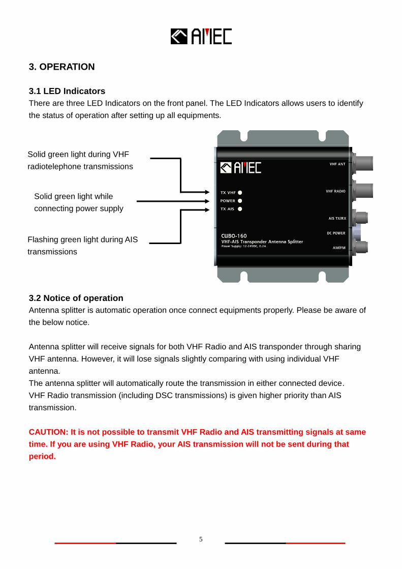
3.1 LED Indicators
There are three LED Indicators on the front panel. The LED Indicators allows users to identify
the status of operation after setting up all equipments.
3.2 Notice of operation
Antenna splitter is automatic operation once connect equipments properly. Please be aware of
the below notice.
Antenna splitter will receive signals for both VHF Radio and AIS transponder through sharing
VHF antenna. However, it will lose signals slightly comparing with using individual VHF
antenna.
The antenna splitter will automatically route the transmission in either connected device.
VHF Radio transmission (including DSC transmissions) is given higher priority than AIS
transmission.
CAUTION: It is not possible to transmit VHF Radio and AIS transmitting signals at same
time. If you are using VHF Radio, your AIS transmission will not be sent during that
period.
Solid green light while
connecting power supply
Flashing green light during AIS
transmissions
Solid green light during VHF
radiotelephone transmissions

6
4. TROUBLESHOOTING
*Note1: You may hear clicks or other noise slightly from AM/FM Receiver during VHF or AIS
Transmission.
*Note2: The receiving signal will reduce slightly due to the insertion loss of the antenna splitter.
“DC Power”
Green LED not lighting Step3: Check power supply voltage and current
Step4: Check polarity of power supply connection
Step1: Check power supply switch and circuit breaker
Step2: Check power supply connection and fuse
“TX VHF”
Green LED not lighting when
VHF Radio is transmitting
Step1: Check whether it is right connector port
Step2: Check any joint of extension cable or connector
Step3: Check extension cable type
“TX AIS”
Green LED not flashing when
AIS transponder is transmitting Step3: Check whether it is right connector port
Step4: Check any joint of extension cable or connector
Step5: Check extension cable type
Step1: Please wait and watch. It might take 30secs
to several minutes in the beginning.
Step2: Check whether VHF Radio is transmitting.

7
1. One Power Indicator
2. One VHF Radio Transmission Indicator
3. One AIS Transponder Transmission Indicator
POWER SUPPLY
Supply Voltage
Operating current (receive)
Operating current (VHF Transmit)
Operating current (AIS Transmit)
12V ~ 24V DC
160mA typical at 12VDC
150mA typical at 12VDC
170mA typical at 12VDC
LED INDICATIONS
ENVIRONMENT
PHYSICAL
Size in mm (W)
Size in mm (H)
Size in mm (D)
Weight
103 mm (140mm with mounting)
50 mm
150 mm w/o connectors
<1kg
5. APPENDIX
5.1 Product Specifications
Operating Temperature -15°C~55°C
Storage Temperature -25°C~70°C
Operating Humidity 95% RH at 40°C
Waterproof IPX5
Standard Magnetic Compass Safe Distance 0.5 m
RF PERFORMANCE
AIS & VHF Radio Frequency Range
Insertion loss, AIS Receive path
Insertion loss, VHF Radio Receive path
Insertion loss, AIS Transmit path
Insertion loss, VHF Radio Transmit path
AIS port
VHF Radio port
FM port
156.025 MHz~162.025 MHz
Typical 4dB
Typical 4dB
Typical 0.8dB
Typical 0.8dB
BNC connector: Max. 12.5W, 50Ω
UHF connector: Max. 25W, 50Ω
75Ω

8
5.2 Dimensions
Front View
Figure 5-2-1 CUBO-160 Front View
Top View
Figure 5-2-2 CUBO-160 Top View
9
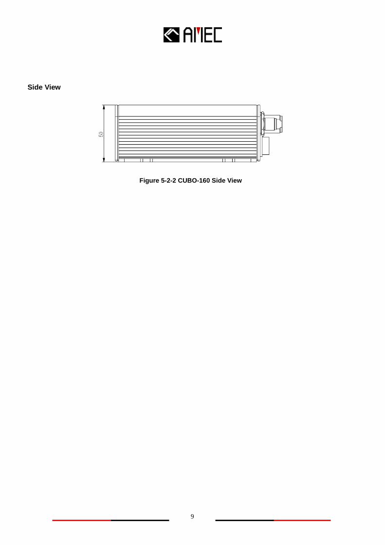
Side View
Figure 5-2-2 CUBO-160 Side View

10
6. AMEC WORLDWIDE WARRANTY
Limited warranty
Subject to the terms, conditions and limitations set forth in this Worldwide Limited Warranty
(hereinafter the “Warranty”), AMEC warrants that its products, when properly installed and used,
will be free from defects in material and workmanship for a period of twelve (12) months, from
the date of first purchase (the „Warranty Period‟)
For the purposes of this warranty, „date of first purchase‟ means the date that the product was
purchased by the first retail customer, or by the institutional customer, or in the case of a
product installed on a new vessel or any other marine related platform by a certified AMEC
original equipment manufacturer (a „AMEC OEM‟), the date that such vessel was purchased by
the first retail customer.
AMEC will, at its sole option, repair or replace any defective products or components returned
during the Warranty Period in accordance with the terms, conditions and limitations set forth
below. Such repairs or replacement will be the sole remedy of the customer under this
Warranty.
Standard Warranty Service
To qualify for standard warranty service the product must be returned to a AMEC-certified
service agent (i) within the Warranty Period, and (ii) within thirty (30) days of the alleged product
failure. Any products returned must be securely packaged and sent pre-paid and insured to
AMEC or to a AMEC-certified service agent. All products returned must be accompanied by a
copy of the original sales receipt to be eligible for standard warranty service.
Obtaining Warranty Service
A list of AMEC-certified service agents is available from AMEC Technical Support at
www.alltekmarine.com
Other conditions
This Warranty is fully transferable provided that you furnish the original proof of purchase to the
AMEC -certified service agent. This Warranty is void if the label bearing the serial number has
been removed or defaced.
Limitation and Exclusions
In addition to any other limitations and exclusions set forth herein, AMEC is not responsible for,
and this Warranty does not cover:

11
Failure due to abuse, misuse, accident, unauthorized alteration, modification or repair,
improper installation or operation (whether or not by a AMEC-certified service agent) or
improper storage, shipping damage or corrosion;
Costs associated with routine system checkouts, alignment/calibration, sea trials or
commissioning;
Defects or damage that result from the use of non-AMEC branded or certified products,
accessories or other peripheral equipment, including without limitation housings, parts, or
software;
Aftermarket software (i.e. all software other than the original operating software sold with the
products);
Products that have been refurbished, reconditioned, or remanufactured (The foregoing does
not apply to products repaired or replaced pursuant to the terms of this Warranty).
Products that have been dismantled resulting in the broken label on the Products;
costs associated with overtime or premium labor costs;
differences in material, coloring or size that may exist between actual products and the
pictures or descriptions of such products in our advertising, advertising literature or on the
Internet;
TO THE EXTENT PERMITTED BY APPLICABLE LAW, THE FOREGOING WARRANTY IS
AMEC’S SOLE WARRANTY AND IS APPLICABLE ONLY TO NEW PRODUCTS
PURCHASED WORLDWIDE. THE PROVISIONS OF THIS WARRANTY ARE IN LIEU OF ANY
OTHER WRITTEN WARRANTY, WHETHER EXPRESSED OR IMPLIED, WRITTEN OR ORAL,
INCLUDING ANY WARRANTY OF MERCHANTABILITY OR FITNESS FOR A PARTICULAR
PURPOSE.
THE LIABILITY OF AMEC TO A CUSTOMER UNDER THIS WARRANTY, WHETHER FOR
BREACH OF CONTRACT, TORT, BREACH OF STATUTORY DUTY OR OTHERWISE SHALL
IN NO EVENT EXCEED AN AMOUNT EQUAL TO THE TOTAL PURCHAE PRICE OF THE
PRODUCT GIVING RISE TO SUCH LIABILITY AND IN NO EVENT SHALL AMEC BE LIABLE
FOR SPECIAL, INCIDENTAL, CONSEQUENTIAL OR INDIRECT DAMAGES OR LOST OF
GOODWILL, REPUTATION, LOSS OF OPPORTUNITY OR INFORMATION, DATA,
SOFTWARE OR APPLICATIONS.
SOME JURISDICTIONS DO NOT ALLOW EXCLUSION OR LIMITATION OF INCIDENTAL OR
CONSEQUENTIAL DAMAGES SO THE ABOVE LIMITATIONS OR EXCLUSIONS MAY NOT
APPLY TO YOU. THIS WARRANTY GIVES YOU SPECIFICLEGAL RIGHTS AND YOU MAY
ALSO HAVE OTHER RIGHTS, WHICH VARY FROM JURISDICTION TO JURISDICTION.

12
This Warranty supersedes and replaces all previous Warranties.
In the event that any term or provision contained in this Warranty is found to be invalid, illegal or
unenforceable by a court of competent jurisdiction, then such provision shall be deemed
modified to the extent necessary to make such provision enforceable by such court, taking into
account the intent of the parties.
No oral or written representations made by AMEC or any seller, reseller or distributor of the
products, including employees and agents thereof, shall create any additional warranty
obligations, increase the scope, or otherwise modify in any manner the terms of this Warranty.
All AMEC products sold or provided hereunder are merely aids to navigation. It is the
responsibility of the user to exercise discretion and proper navigational skill independent of any
AMEC product.
7. DECLARATION OF CONFORMITY
Hereby, Alltek Marine Electronics Corp. (AMEC) declares that this CUBO-160 is in compliance
with the essential requirements and other relevant provisions of Directive 1999/5/EC.