CMK2 Series - ckdpneumatic.comckdpneumatic.com/pdf/CMK2.pdf · CMK2 Series Specifications Cylinder...
12
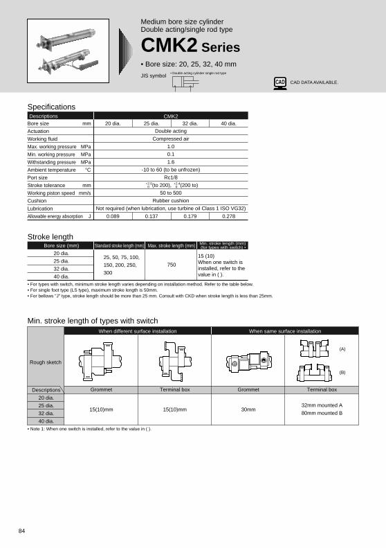
84 JIS symbol Medium bore size cylinder Double acting/single rod type CMK2 Series • Bore size: 20, 25, 32, 40 mm • Double acting cylinder single rod type • For types with switch, minimum stroke length varies depending on installation method. Refer to the table below. • For single foot type (LS type), maximum stroke length is 50mm. • For bellows "J" type, stroke length should be more than 25 mm. Consult with CKD when stroke length is less than 25mm. Specifications Descriptions CMK2 Bore size mm Actuation Working fluid Max. working pressure MPa Min. working pressure MPa Withstanding pressure MPa Ambient temperature °C Port size Stroke tolerance mm Working piston speed mm/s Cushion Lubrication Allowable energy absorption J 20 dia. 0.089 25 dia. 0.137 32 dia. 0.179 40 dia. 0.278 Double acting Compressed air 1.0 0.1 1.6 -10 to 60 (to be unfrozen) Rc1/8 (to 200), (200 to) 50 to 500 Rubber cushion Not required (when lubrication, use turbine oil Class 1 ISO VG32) +2.0 0 +2.4 0 Stroke length Bore size (mm) 20 dia. 25 dia. 32 dia. 40 dia. Standard stroke length (mm) Max. stroke length (mm) Min. stroke length (mm) (for types with switch) • 25, 50, 75, 100, 150, 200, 250, 300 15 (10) When one switch is installed, refer to the value in ( ). 750 • Note 1: When one switch is installed, refer to the value in ( ). Min. stroke length of types with switch Rough sketch Descriptions 20 dia. 25 dia. 32 dia. 40 dia. Grommet Terminal box Grommet Terminal box When different surface installation When same surface installation 15(10)mm 15(10)mm 30mm 32mm mounted A 80mm mounted B (A) (B) CAD DATA AVAILABLE.
Transcript of CMK2 Series - ckdpneumatic.comckdpneumatic.com/pdf/CMK2.pdf · CMK2 Series Specifications Cylinder...
84
JIS symbol
Medium bore size cylinderDouble acting/single rod type
CMK2 Series• Bore size: 20, 25, 32, 40 mm
• Double acting cylinder single rod type
• For types with switch, minimum stroke length varies depending on installation method. Refer to the table below.• For single foot type (LS type), maximum stroke length is 50mm.• For bellows "J" type, stroke length should be more than 25 mm. Consult with CKD when stroke length is less than 25mm.
SpecificationsDescriptions CMK2
Bore size mm
Actuation
Working fluid
Max. working pressure MPa
Min. working pressure MPa
Withstanding pressure MPa
Ambient temperature °CPort size
Stroke tolerance mm
Working piston speed mm/s
Cushion
Lubrication
Allowable energy absorption J
20 dia.
0.089
25 dia.
0.137
32 dia.
0.179
40 dia.
0.278
Double acting
Compressed air
1.0
0.1
1.6
-10 to 60 (to be unfrozen)
Rc1/8
(to 200), (200 to)
50 to 500
Rubber cushion
Not required (when lubrication, use turbine oil Class 1 ISO VG32)
+2.0 0
+2.4 0
Stroke lengthBore size (mm)
20 dia.
25 dia.
32 dia.
40 dia.
Standard stroke length (mm) Max. stroke length (mm) Min. stroke length (mm) (for types with switch) •
25, 50, 75, 100,
150, 200, 250,
300
15 (10)When one switch is installed, refer to the value in ( ).
750
• Note 1: When one switch is installed, refer to the value in ( ).
Min. stroke length of types with switch
Rough sketch
Descriptions
20 dia.
25 dia.
32 dia.
40 dia.
Grommet Terminal box Grommet Terminal box
When different surface installation When same surface installation
15(10)mm 15(10)mm 30mm32mm mounted A
80mm mounted B
(A)
(B)
CAD DATA AVAILABLE.
85
Standard type
Med
ium
bo
re size cylind
er
SCP * 2
CMK2
CMA2
SCM
SCA2
SCS
CKV2
CAT
MDC2
MVC
SMD2
SSD
FC *
JSB3
UCAC
LCS
LCY
STR2
UCA2
STK
USSD
USC
MFC
GLC
SHC
CAC3
HCM
HCA
MRL2
SRL2
SRG
SRM
SRT
SRB2
CAV2/COV * 2
MSD/MSDG
ULKP/ULKJSK2/JSM2
STS/STL
SSD (large)
JSC3 (medium)JSC3 (large)
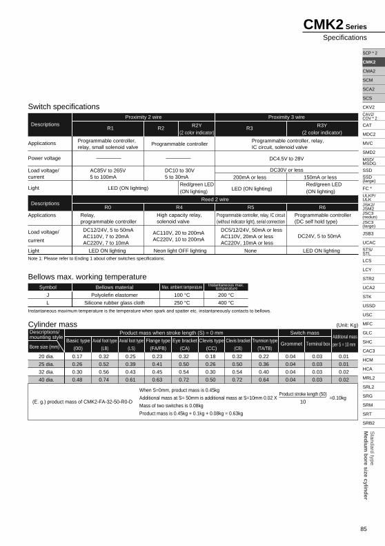
CMK2 Series
Specifications
Cylinder mass
Basic type
(00)
20 dia.
25 dia.
32 dia.
40 dia.
Axial foot type
(LB)
Axial foot type
(LS)
Flange type
(FA/FB)
Eye bracket
(CA)
Clevis type
(CC)
Clevis bracket
(CB)
Trunnion type
(TA/TB)Grommet Terminal box
Additional mass
per S = 10 mm
Descriptions/mounting style
Bore size (mm)
Product mass when stroke length (S) = 0 mm Switch mass
0.17
0.26
0.30
0.48
0.32
0.52
0.56
0.74
0.25
0.39
0.43
0.61
0.23
0.41
0.45
0.63
0.32
0.50
0.54
0.72
0.18
0.26
0.30
0.50
0.32
0.50
0.54
0.72
0.22
0.36
0.40
0.64
0.04
0.04
0.04
0.04
0.03
0.03
0.03
0.03
0.01
0.01
0.02
0.02
(Unit: Kg)
(E. g.) product mass of CMK2-FA-32-50-R0-D
When S=0mm, product mass is 0.45kg
Additional mass at S= 50mm is additional mass at S=10mm 0.02 X =0.10kg
Mass of two switches is 0.08kg
Product mass is 0.45kg + 0.1kg + 0.08kg = 0.63kg
Product stroke length (50)
10
Note 1: Please refer to Ending 1 about other switches specifications.
Instantaneous maximum temperature is the temperature when spark and spatter etc. instantaneously contacts to bellows.
Switch specifications
Bellows max. working temperature
Applications
Power voltage
Load voltage/current
Light
R3Y(2 color indicator)
R3R2Y(2 color indicator)
R2R1Descriptions
Programmable controller, relay, small solenoid valve
AC85V to 265V5 to 100mA
Programmable controller
DC10 to 30V5 to 30mA
Programmable controller, relay, IC circuit, solenoid valve
DC4.5V to 28V
DC30V or less
Red/green LED (ON lighting) LED (ON lighting)
Red/green LED (ON lighting)
200mA or less 150mA or less
LED (ON lighting)
Applications
Load voltage/
current
Light
R0 R4 R5
Proximity 2 wire
Reed 2 wire
Proximity 3 wire
R6
Max. ambient temperature Instantaneous max. temperature
Descriptions
Symbol Bellows material
100 °C250 °C
200 °C400 °C
J
L
Polyolefin elastomer
Silicone rubber glass cloth
Relay, programmable controller
High capacity relay, solenoid valve
Programmable controller, relay, IC circuit (without indicator light), serial connection
Programmable controller (DC self hold type)
DC12/24V, 5 to 50mAAC110V, 7 to 20mAAC220V, 7 to 10mA
AC110V, 20 to 200mAAC220V, 10 to 200mA
DC5/12/24V, 50mA or lessAC110V, 20mA or lessAC220V, 10mA or less
DC24V, 5 to 50mA
LED ON lighting Neon light OFF lighting None LED ON lighting
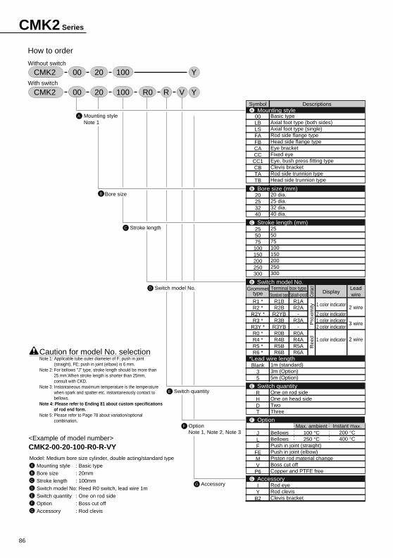
86
CMK2 Series
<Example of model number>CMK2-00-20-100-R0-R-VYModel: Medium bore size cylinder, double acting/standard type
Mounting style : Basic type
Bore size : 20mm
Stroke length : 100mm
Switch model No: Reed R0 switch, lead wire 1m
Switch quantity : One on rod side
Option : Boss cut off
Accessory : Rod clevis
Caution for model No. selectionNote 1: Applicable tube outer diameter of F; push in joint
(straight), FE; push in joint (elbow) is 6 mm.Note 2: For bellows "J" type, stroke length should be more than
25 mm.When stroke length is shorter than 25mm, consult with CKD.
Note 3: Instantaneous maximum temperature is the temperature when spark and spatter etc. instantaneously contact to bellows.
Note 4: Please refer to Ending 81 about custom specifications of rod end form.
Note 5: Please refer to Page 78 about variation/optional combination.
A
B
C
D
E
F
G
How to order
Without switch
With switch
Symbol Descriptions
C Stroke length
D Switch model No.
E Switch quantity
F OptionNote 1, Note 2, Note 3
00LBLSFAFBCACC
CC1CBTATB
20253240
255075
100150200250300
Grommettype
R1 *R2 *
R2Y *R3 *
R3Y *R0 *R4 *R5 *R6 *
Blank35
RHDT
JLF
FEMV
P6
IY
B2
Basic typeAxial foot type (both sides)Axial foot type (single)Rod side flange typeHead side flange typeEye bracketFixed eyeEye, bush press fitting typeClevis bracketRod side trunnion typeHead side trunnion type
20 dia.25 dia.32 dia.40 dia.
255075100150200250300
1m (standard)3m (Option)5m (Option)
One on rod sideOne on head sideTwoThree
BellowsBellowsPush in joint (straight)Push in joint (elbow)Piston rod material changeBoss cut offCopper and PTFE free
Rod eyeRod clevisClevis bracket
Mounting styleA
Bore size (mm)B
Stroke length (mm)C
Switch model No.D
Switch quantityE
OptionF
AccessoryG
*Lead wire length
G Accessory
Conta
ctP
roxi
mity
Ree
d
CMK2 VR Y10000 20 R0
CMK2 Y10000 20
A Mounting styleNote 1
B Bore size
Max. ambient100 °C250 °C
Instant max.200 °C400 °C
Terminal box type Leadwire
2 wire
3 wire
2 wire
Standard typeR1BR2B
R2YBR3B
R3YBR0BR4BR5BR6B
Splash-proofR1AR2A
-R3A
-R0AR4AR5AR6A
Display
1 color indicator
2 color indicator1 color indicator2 color indicator
1 color indicator
87
Standard type
Med
ium
bo
re size cylind
er
SCP * 2
CMK2
CMA2
SCM
SCA2
SCS
CKV2
CAT
MDC2
MVC
SMD2
SSD
FC *
JSB3
UCAC
LCS
LCY
STR2
UCA2
STK
USSD
USC
MFC
GLC
SHC
CAC3
HCM
HCA
MRL2
SRL2
SRG
SRM
SRT
SRB2
CAV2/COV * 2
MSD/MSDG
ULKP/ULKJSK2/JSM2
STS/STL
SSD (large)
JSC3 (medium)JSC3 (large)
CMK2 Series
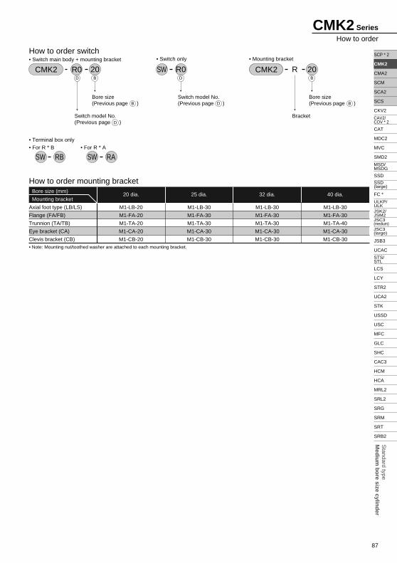
How to order
Switch model No.(Previous page )
How to order switch• Switch main body + mounting bracket
CMK2 R0 20B
B D
D
D
Bore size(Previous page )
Switch model No.(Previous page )
• Mounting bracket
CMK2 20RB
BBore size(Previous page )
Bracket
• Switch only
SW R0D
• Terminal box only• For R * B
SW RB• For R * A
SW RA
How to order mounting bracket
Axial foot type (LB/LS)
Flange (FA/FB)
Trunnion (TA/TB)
Eye bracket (CA)
Clevis bracket (CB)
20 dia. 25 dia. 32 dia. 40 dia.Bore size (mm)
Mounting bracket
M1-LB-30
M1-FA-30
M1-TA-40
M1-CA-30
M1-CB-30
M1-LB-30
M1-FA-30
M1-TA-30
M1-CA-30
M1-CB-30
M1-LB-30
M1-FA-30
M1-TA-30
M1-CA-30
M1-CB-30
M1-LB-20
M1-FA-20
M1-TA-20
M1-CA-20
M1-CB-20• Note: Mounting nut/toothed washer are attached to each mounting bracket.
88
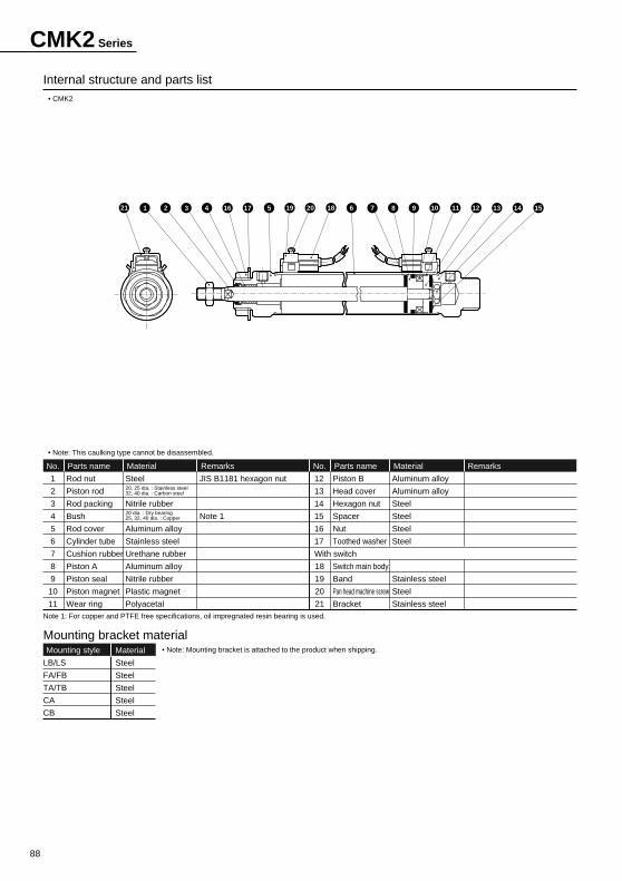
• CMK2
• Note: This caulking type cannot be disassembled.
Internal structure and parts list
1
2
3
4
5
6
7
8
9
10
11
Rod nut
Piston rod
Rod packing
Bush
Rod cover
Cylinder tube
Cushion rubber
Piston A
Piston seal
Piston magnet
Wear ring
Parts name
Steel
Nitrile rubber
Aluminum alloy
Stainless steel
Urethane rubber
Aluminum alloy
Nitrile rubber
Plastic magnet
Polyacetal
Material
JIS B1181 hexagon nut
Note 1
RemarksNo.
12
13
14
15
16
17
With switch
18
19
20
21
Piston B
Head cover
Hexagon nut
Spacer
Nut
Toothed washer
Switch main body
Band
Pan head machine screw
Bracket
Parts name
Aluminum alloy
Aluminum alloy
Steel
Steel
Steel
Steel
Stainless steel
Steel
Stainless steel
Material RemarksNo.
20, 25 dia. : Stainless steel32, 40 dia. : Carbon steel
20 dia. : Dry bearing25, 32, 40 dia. : Copper
Note 1: For copper and PTFE free specifications, oil impregnated resin bearing is used.
Mounting bracket materialMounting style
LB/LS
FA/FB
TA/TB
CA
CB
Material
Steel
Steel
Steel
Steel
Steel
• Note: Mounting bracket is attached to the product when shipping.
CMK2 Series
21 1 2 3 4 16 17 5 19 20 18 6 7 8 9 10 11 12 13 14 15
95
SCP*2
CMK2
CMA2
SCM
SCG
SCA2
SCS
CKV2
CA/OV2
SSD
CAT
MDC2
MVC
SMD2
MSD*
FC*
STK
ULK*
JSK/M2
JSG
JSC3
USSD
USC
JSB3
LMB
STG
STS/L
LCS
LCG
LCM
LCT
LCY
STR2
UCA2
HCM
HCA
SRL2
SRG
SRM
SRT
MRL2
MRG2
SM-25
CAC3
UCAC
RCC2
MFC
SHC
GLC
Ending
Med
ium
bor
e si
ze c
ylin
der
Sta
ndar
d ty
pe
Basic type (00)
RD: Rod side max. sensitive positionHD: Head side max. sensitive position
Dimensions
20
23
23
25
18
20
20
22
21.4
26.4
33.6
41.6
28
32
36
45
26
35
35
35
12
14
14
14
M8 x 1.0
M10 x 1.25
M10 x 1.25
M12 x 1.5
66
69
69
73
M18 x 1.5
M26 x 1.5
M26 x 1.5
M26 x 1.5
10
12
12
14
8
10
10
12
5
5
5
6
5
6
6
7
24
30
34
43
14
16
16
16
24
23
23
23
124
131
131
137
44
46
46
48
Symbol
Bore size (mm)
Basic dimensions of basic type (00)
With switch
A C D
13
17
17
19
B F
7.0
8.5
8.5
10.5
17.3
19.8
24.3
28.3
19.5
22.0
25.5
29.5
22
18
15
12
HD
8.0
9.5
9.5
11.5
RD
3.0
4.5
4.5
6.5
GD
4.0
5.5
5.5
7.0
GC P P1 (P )°
HA K KK LL MB MM MN MO T U V WF X XF
20
25
32
40
Symbol
Bore size (mm)
20
25
32
40
Note 1: For dimensions, round up decimal point or less.Note 2: Refer to page 188 for the HD, RD, and projecting dimensions of the T1* and T8* switches and 2-color indicator switch with preventive maintenance output.Note 3: Refer to page 190 for dimensions of accessories.
With bellows
30
32
32
34
b
30
46
46
46
d
(stroke length/3) + 6
(stroke length/3.25) + 7
(stroke length/3.25) + 7
(stroke length/3.25) + 7
(with bellows)
WF +X + + stroke length
d
Ab
8P
(P )
P1
HA
2-Rc1/8
HDRD
X + stroke length
LL + stroke length V
K
8
16GD30.5
WFA
C V GC 30.516
8
T
D
1010
2-width across flats U
MBWidth across flats B
KK
XFMB
F
MN
(2
wid
th)
MO
MM
CMK2 Series
Double acting
96
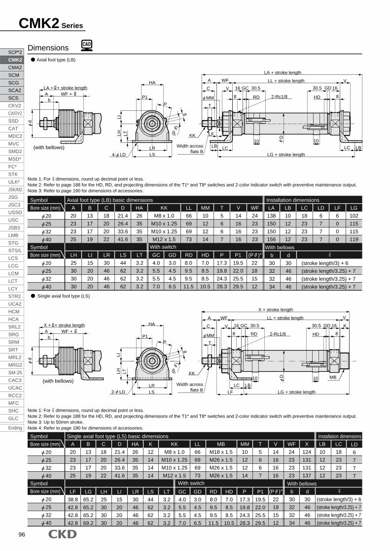
CMK2 Series
Axial foot type (LB)
Single axial foot type (LS)
Note 1: For dimensions, round up decimal point or less.Note 2: Refer to page 188 for the HD, RD, and projecting dimensions of the T1* and T8* switches and 2-color indicator switch with preventive maintenance output.Note 3: Refer to page 190 for dimensions of accessories.
Note 1: For dimensions, round up decimal point or less.Note 2: Refer to page 188 for the HD, RD, and projecting dimensions of the T1* and T8* switches and 2-color indicator switch with preventive maintenance output.Note 3: Up to 50mm stroke.Note 4: Refer to page 190 for dimensions of accessories.
Dimensions
Symbol
Bore size (mm)
Axial foot type (LB) basic dimensions Installation dimensions
With switch
8.0
9.5
9.5
11.5
RD
3.0
4.5
4.5
6.5
GD
4.0
5.5
5.5
7.0
GC
102
115
115
119
LG
6
0
0
0
LF
6
7
7
7
LD
18
23
23
23
LC
10
12
12
12
LB
138
150
150
156
LA
24
23
23
23
WF
14
16
16
16
V
5
6
6
7
T
10
12
12
14
MM
66
69
69
73
LL
M8 x 1.0
M10 x 1.25
M10 x 1.25
M12 x 1.5
KK
26
35
35
35
HA
21.4
26.4
33.6
41.6
D
18
20
20
22
C
13
17
17
19
B
20
23
23
25
A
30
46
46
46
LR
44
62
62
62
LS
3.2
3.2
3.2
3.2
LT
15
20
20
20
LI
25
30
30
30
LH
22
18
15
12
(P )°
17.3
19.8
24.3
28.3
P
19.5
22.0
25.5
29.5
P1
7.0
8.5
8.5
10.5
HD
20
25
32
40
Symbol
Bore size (mm)
20
25
32
40
Symbol
Bore size (mm)
Single axial foot type (LS) basic dimensions Installation dimensions
With switch
6
7
7
7
LD18
23
23
23
LC
10
12
12
12
LB
124
131
131
137
X
24
23
23
23
WF
14
16
16
16
V
5
6
6
7
T
10
12
12
14
MM
M18 x 1.5
M26 x 1.5
M26 x 1.5
M26 x 1.5
MB
66
69
69
73
LL
M8 x 1.0
M10 x 1.25
M10 x 1.25
M12 x 1.5
KK
12
14
14
14
K
26
35
35
35
HA
21.4
26.4
33.6
41.6
D
18
20
20
22
C
20
23
23
25
A
13
17
17
19
B
30
46
46
46
LR
44
62
62
62
LS
3.2
3.2
3.2
3.2
LT
4.0
5.5
5.5
7.0
GC
3.0
4.5
4.5
6.5
GD
7.0
8.5
8.5
10.5
HD
8.0
9.5
9.5
11.5
RD
17.3
19.8
24.3
28.3
P
19.5
22.0
25.5
29.5
P1
15
20
20
20
LI
25
30
30
30
LH
65.2
65.2
65.2
69.2
LG
38.8
42.8
42.8
42.8
LF
Symbol
Bore size (mm)
With bellows
30
32
32
34
b
30
46
46
46
d
(stroke length/3) + 6
(stroke length/3.25) + 7
(stroke length/3.25) + 7
(stroke length/3.25) + 7
With bellows
22
18
15
12
(P )°
30
46
46
46
d
30
32
32
34
b
(stroke length/3) + 6
(stroke length/3.25) + 7
(stroke length/3.25) + 7
(stroke length/3.25) + 7
20
25
32
40
20
25
32
40
WF +LA + + stroke length
d
Ab
D
(P
)
8
LF
LG + stroke length
LCLC LBLB
LA + stroke length
2-Rc1/8 HDRD
1010Width across
flats B
KK
MM
LL + stroke length V
8
16GD30.5
WFA
C V GC 30.5
8
T
4- LD LSLR
LTLHLI
PP1
HA16
WF +X + + stroke length
d
Ab
MB
LG + stroke lengthLF
LC LB
D
HDRD
1010
LL + stroke length V
K
8
16GD30.5
WFA
C V GC 30.516
8
T
X + stroke length
Width acrossflats B
KK
MM
LSLR
LTLHLI
HA
P1P
2- LD
(P
)
8
2-Rc1/8
(with bellows)
(with bellows)
SCP*2
CMK2
CMA2
SCM
SCG
SCA2
SCS
CKV2
CA/OV2
SSD
CAT
MDC2
MVC
SMD2
MSD*
FC*
STK
ULK*
JSK/M2
JSG
JSC3
USSD
USC
JSB3
LMB
STG
STS/L
LCS
LCG
LCM
LCT
LCY
STR2
UCA2
HCM
HCA
SRL2
SRG
SRM
SRT
MRL2
MRG2
SM-25
CAC3
UCAC
RCC2
MFC
SHC
GLC
Ending
97
SCP*2
CMK2
CMA2
SCM
SCG
SCA2
SCS
CKV2
CA/OV2
SSD
CAT
MDC2
MVC
SMD2
MSD*
FC*
STK
ULK*
JSK/M2
JSG
JSC3
USSD
USC
JSB3
LMB
STG
STS/L
LCS
LCG
LCM
LCT
LCY
STR2
UCA2
HCM
HCA
SRL2
SRG
SRM
SRT
MRL2
MRG2
SM-25
CAC3
UCAC
RCC2
MFC
SHC
GLC
Ending
Med
ium
bor
e si
ze c
ylin
der
Sta
ndar
d ty
pe
CMK2 Series
Double acting
Rod side flange type (FA)
Note 1: For dimensions, round up decimal point or less.Note 2: Refer to page 188 for the HD, RD, and projecting dimensions of the T1* and T8* switches and 2-color indicator switch with preventive maintenance output.Note 3: Refer to page 190 for dimensions of accessories.
Head side flange type (FB)
Note 1: For dimensions, round up decimal point or less.Note 2: Refer to page 188 for the HD, RD, and projecting dimensions of the T1* and T8* switches and 2-color indicator switch with preventive maintenance output.Note 3: Refer to page 190 for dimensions of accessories.
Dimensions
Symbol
Bore size (mm)
Rod side flange type (FA) basic dimensions Installation dimensions
With switch
6
7
7
7
FD
20
28
28
28
FC
124
131
131
137
X
24
23
23
23
WF
14
16
16
16
V
5
6
6
7
T
10
12
12
14
MM
M18 x 1.5
M26 x 1.5
M26 x 1.5
M26 x 1.5
MB
66
69
69
73
LL
M8 x 1.0
M10 x 1.25
M10 x 1.25
M12 x 1.5
KK
M18 x 1.5
M26 x 1.5
M26 x 1.5
M26 x 1.5
MB
66
69
69
73
LL
M8 x 1.0
M10 x 1.25
M10 x 1.25
M12 x 1.5
KK
12
14
14
14
K
26
35
35
35
HA
28
32
36
45
F
21.4
26.4
33.6
41.6
D
18
20
20
22
C
13
17
17
19
B
20
23
23
25
A
3.2
4.5
4.5
4.5
FT
4.0
5.5
5.5
7.0
GC
3.0
4.5
4.5
6.5
GD
8.0
9.5
9.5
11.5
RD
7.0
8.5
8.5
10.5
HD
29
41
41
41
FP
54
80
80
80
FM
40
64
64
64
FL
34
44
44
44
FH
83.2
89.5
89.5
93.5
FG
20.8
18.5
18.5
18.5
FF
20
25
32
40
Symbol
Bore size (mm)
20
25
32
40
Symbol
Bore size (mm)
Head side flange type (FB) basic dimensions Installation dimensions
With switch
34
44
44
44
FH
6
7
7
7
FD
20
28
28
28
FC
124
131
131
137
X
24
23
23
23
WF
14
16
16
16
V
5
6
6
7
T
10
12
12
14
MM
12
14
14
14
K
26
35
35
35
HA
21.4
26.4
33.6
41.6
D
18
20
20
22
C
13
17
17
19
B
20
23
23
25
A
3.2
4.5
4.5
4.5
FT
4.0
5.5
5.5
7.0
GC
3.0
4.5
4.5
6.5
GD
8.0
9.5
9.5
11.5
RD
7.0
8.5
8.5
10.5
HD
29
41
41
41
FP
54
80
80
80
FM
40
64
64
64
FL
93.2
96.5
96.5
100.5
FJ
20
25
32
40
Symbol
Bore size (mm)
20
25
32
40
With bellows
30
32
32
34
b
30
46
46
46
d
(stroke length/3) + 6
(stroke length/3.25) + 7
(stroke length/3.25) + 7
(stroke length/3.25) + 7
With bellows
30
32
32
34
b
30
46
46
46
d
(stroke length/3) + 6
(stroke length/3.25) + 7
(stroke length/3.25) + 7
(stroke length/3.25) + 7
WF +X + + stroke length
d
Ab
4- FD
FH
FC
FMFL
HA
FJ + stroke lengthFT
K
MB
T
D
HDRD
1010
LL + stroke length V
8
16GD30.5
WFA
C V GC 30.516
8
X + stroke length
Width across flats B
KK
MM 2-Rc1/8
(with bellows)
(with bellows)
WF +X + + stroke length
d
Ab FP
FH
FC
FMFL MB
FG + stroke lengthFFFT
D
HDRD
1010
F
LL + stroke length V
K
8
16GD30.5HA
WFA
C V GC 30.516
8
T
X + stroke length
4- FDWidth across flats B
KK
MM 2-Rc1/8
FP
98
CMK2 Series
Eye bracket type (CA)
Note 1: For dimensions, round up decimal point or less.Note 2: Refer to page 188 for the HD, RD, and projecting dimensions of the T1* and T8* switches and 2-color indicator switch with preventive maintenance output.Note 3: This is not a piping port.Note 4: Refer to page 190 for dimensions accessories.
Clevis bracket type (CB)
Note 1: For dimensions, round up decimal point or less.Note 2: Refer to page 188 for the HD, RD, and projecting dimensions of the T1* and T8* switches and 2-color indicator switch with preventive maintenance output.Note 3: This is not a piping port.Note 4: Refer to page 190 for dimensions accessories.
Dimensions
Symbol
Bore size (mm)
Eye bracket type (CA) basic dimensions Installation dimensions
With switch
26
35
35
35
CH
10
12
12
12
CD
10
12
12
12
CC
14
18
18
18
CB
165
177
177
183
CA
24
23
23
23
WF
14
16
16
16
V
5
6
6
7
T
10
12
12
14
MM
M18 x 1.5
M26 x 1.5
M26 x 1.5
M26 x 1.5
MB
66
69
69
73
LL
M8 x 1.0
M10 x 1.25
M10 x 1.25
M12 x 1.5
KK
12
14
14
14
K
21.4
26.4
33.6
41.6
D
18
20
20
22
C
13
17
17
19
B
20
23
23
25
A
M18 x 1.5
M26 x 1.5
M26 x 1.5
M26 x 1.5
MB
66
69
69
73
LL
M8 x 1.0
M10 x 1.25
M10 x 1.25
M12 x 1.5
KK
12
14
14
14
K
21.4
26.4
33.6
41.6
D
18
20
20
22
C
13
17
17
19
B
20
23
23
25
A
8
10
10
10
CQ
4.0
5.5
5.5
7.0
GC
3.0
4.5
4.5
6.5
GD
8.0
9.5
9.5
11.5
RD
7.0
8.5
8.5
10.5
HD
17.3
19.8
24.3
28.3
P
19.5
22.0
25.5
29.5
P1
22
18
15
12
(P )°
28
37
37
37
CP
22
26
26
26
CO
24
30
30
30
CM
31
32
32
32
CL
135
142
142
146
CJ
20
25
32
40
Symbol
Bore size (mm)
20
25
32
40
+0.058 0
+0.070 0
+0.070 0
+0.070 0
With bellows
30
32
32
34
b
30
46
46
46
d
(stroke length/3) + 6
(stroke length/3.25) + 7
(stroke length/3.25) + 7
(stroke length/3.25) + 7
With bellows
30
32
32
34
b
30
46
46
46
d
(stroke length/3) + 6
(stroke length/3.25) + 7
(stroke length/3.25) + 7
(stroke length/3.25) + 7
Symbol
Bore size (mm)
With switch
26
35
35
35
CH
10
12
12
12
CD
10
12
12
12
CC
14
18
18
18
CB
165
177
177
183
CA
24
23
23
23
WF
14
16
16
16
V
5
6
6
7
T
10
12
12
14
MM
19
25
25
25
CV
8
10
10
10
CW
4.0
5.5
5.5
7.0
GC
3.0
4.5
4.5
6.5
GD
8.0
9.5
9.5
11.5
RD
7.0
8.5
8.5
10.5
HD
17.3
19.8
24.3
28.3
P
19.5
22.0
25.5
29.5
P1
22
18
15
12
(P )°
28
37
37
37
CP
22
26
26
26
CO
24
30
30
30
CM
31
32
32
32
CL
135
142
142
146
CJ
20
25
32
40
Symbol
Bore size (mm)
20
25
32
40
+0.058 0
+0.070 0
+0.070 0
+0.070 0
Clevis bracket type (CB) basic dimensions. Installation dimensions
CL
WF +CA + + stroke length
d
Ab
CO
MB
P
8
(P
)
P1
CH
CP
0-0.2CQ
CDH10
CJ + stroke length
CCCB
CA + stroke length
CMCL
8
16 30.5GCVC
A WF
30.5 GD16
8Note 4
LL + stroke length
MM
10 10
RD HD2-Rc1/8
D
K
KK
T
Width across flats B
Width across flats B
WF +
d
Ab
CO
CV
P
8
(P
)
P1
CH
CP
+0.2+0.1CWMB
CJ + stroke length
CCCB
CA + stroke length
D
HDRD
1010
LL + stroke length
CM
8
16GD30.5
WFA
C V GC 30.516
8
KT
KK
MM 2-Rc1/8 CDH10
(with bellows)
(with bellows)
Note 4
CA + + stroke length
SCP*2
CMK2
CMA2
SCM
SCG
SCA2
SCS
CKV2
CA/OV2
SSD
CAT
MDC2
MVC
SMD2
MSD*
FC*
STK
ULK*
JSK/M2
JSG
JSC3
USSD
USC
JSB3
LMB
STG
STS/L
LCS
LCG
LCM
LCT
LCY
STR2
UCA2
HCM
HCA
SRL2
SRG
SRM
SRT
MRL2
MRG2
SM-25
CAC3
UCAC
RCC2
MFC
SHC
GLC
Ending
99
SCP*2
CMK2
CMA2
SCM
SCG
SCA2
SCS
CKV2
CA/OV2
SSD
CAT
MDC2
MVC
SMD2
MSD*
FC*
STK
ULK*
JSK/M2
JSG
JSC3
USSD
USC
JSB3
LMB
STG
STS/L
LCS
LCG
LCM
LCT
LCY
STR2
UCA2
HCM
HCA
SRL2
SRG
SRM
SRT
MRL2
MRG2
SM-25
CAC3
UCAC
RCC2
MFC
SHC
GLC
Ending
Med
ium
bor
e si
ze c
ylin
der
Sta
ndar
d ty
pe
CMK2 Series
Double acting
Symbol
Bore size (mm)
Fixed eye (CC) basic dimensions Installation dimensions
With switch
9
9
12
14
CC
12
12
14
16
CB
131
136
141
151
CA
24
23
23
23
WF
14
16
16
16
V
24
30
34
43
U
5
6
6
7
T
10
12
12
14
MM
M18 x 1.5
M26 x 1.5
M26 x 1.5
M26 x 1.5
MB
66
69
69
73
LL
M8 x 1.0
M10 x 1.25
M10 x 1.25
M12 x 1.5
KK
28
32
36
45
F
12
14
14
14
K
21.4
26.4
33.6
41.6
D
18
20
20
22
C
13
17
17
19
B
20
23
23
25
A
M18 x 1.5
M26 x 1.5
M26 x 1.5
M26 x 1.5
MB
66
69
69
73
LL
M8 x 1.0
M10 x 1.25
M10 x 1.25
M12 x 1.5
KK
28
32
36
45
F
12
14
14
14
K
21.4
26.4
33.6
41.6
D
18
20
20
22
C
13
17
17
19
B
20
23
23
25
A
3.0
4.5
4.5
6.5
GD
8.0
9.5
9.5
11.5
RD
7.0
8.5
8.5
10.5
HD
17.3
19.8
24.3
28.3
P
19.5
22.0
25.5
29.5
P1
22
18
15
12
(P )°
4.0
5.5
5.5
7.0
GC
16
16
16
20
CQ
22
24
24
30
CO
21
21
26
30
CM
102
104
106
112
CJ
20
25
32
40
Symbol
Bore size (mm)
20
25
32
40
8
8
10
12
CD+0.058 0
+0.058 0
+0.058 0
+0.070 0
Note 1: For dimensions, round up decimal point or less.Note 2: Refer to page 188 for the HD, RD, and projecting dimensions of the T1* and T8* switches and 2-color indicator switch with preventive maintenance output.Note 3: Refer to page 190 for dimensions of accessories.
With bellows
30
32
32
34
b
30
46
46
46
d
(stroke length/3) + 6
(stroke length/3.25) + 7
(stroke length/3.25) + 7
(stroke length/3.25) + 7
With bellows
30
32
32
34
b
30
46
46
46
d
(stroke length/3) + 6
(stroke length/3.25) + 7
(stroke length/3.25) + 7
(stroke length/3.25) + 7
Fixed eye (CC) with bracket (option symbol B2) Eye bush press fitted type (CC1) with bracket (option symbol B2)
Fixed eye (CC)Eye bush press fitted type (CC1)
Dimensions
Note 1: For dimensions, round up decimal point or less.Note 2: Refer to page 188 for the HD, RD, and projecting dimensions of the T1* and T8* switches and 2-color indicator switch with preventive maintenance output.Note 3: Refer to page 190 for dimensions of accessories.
Fixed eye (CC) with bracket (option symbol B2) basic dimensionsSymbol
Bore size (mm)
Installation dimensions
With switch
21
21
26
30
CM
102
104
106
112
CJ
131
136
141
151
CA
24
23
23
23
WF
14
16
16
16
V
24
30
34
43
U
5
6
6
7
T
10
12
12
14
MM
8.0
9.5
9.5
11.5
RD
7.0
8.5
8.5
10.5
HD
17.3
19.8
24.3
28.3
P
19.5
22.0
25.5
29.5
P1
22
18
15
12
(P )°
3.0
4.5
4.5
6.5
GD
4.0
5.5
5.5
7.0
GC
76
76
76
80
CS
56
56
56
60
CR
16
16
16
20
CQ
22
24
24
30
CO
20
25
32
40
Symbol
Bore size (mm)
20
25
32
40
WF +
d
Ab
U
-0.1-0.3CQ
P1
F
CO
P
8
(P
)
CA + stroke length
CJ + stroke length
CM
CCCB
D
HDRD
1010
LL + stroke length
8
16GD30.5
WFA
C V GC 30.516
8
KT
MM 2-Rc1/8 CDH10
MBWidth across flats B
KK
WF +
d
Ab
CSCR
1010 2020
50
-0.1-0.3CQ
CO
F
P
8
(P
)
U
4-oval hole 7 x 11
3.2
55407.5
20
T K
8
CA + stroke length
16 30.5GCVC
A WF
30.5 GD16
8
CJ + stroke length
LL + stroke length
MM
10 10
RD HD
D
CM
MBWidth across flats B
KK
2-Rc1/8
(with bellows)
(with bellows)
P1
CA + + stroke length
CA + + stroke length
100
CMK2 Series
Rod side trunnion type (TA) with bracket (option symbol B2)
Symbol
Bore size (mm)
Rod side trunnion type (TA) basic dimensions Installation dimensions
With switch
4.5
5.5
5.5
5.5
TB
124
131
131
137
X
24
23
23
23
WF
14
16
16
16
V
5
6
6
7
T
10
12
12
14
MM
M18 x 1.5
M26 x 1.5
M26 x 1.5
M26 x 1.5
MB
66
69
69
73
LL
M8 x 1.0
M10 x 1.25
M10 x 1.25
M12 x 1.5
KK
12
14
14
14
K
28
32
36
45
F
26
35
35
35
HA
21.4
26.4
33.6
41.6
D
18
20
20
22
C
13
17
17
19
B
20
23
23
25
A
M18 x 1.5
M26 x 1.5
M26 x 1.5
M26 x 1.5
MB
66
69
69
73
LL
M8 x 1.0
M10 x 1.25
M10 x 1.25
M12 x 1.5
KK
12
14
14
14
K
28
32
36
45
F
26
35
35
35
HA
21.4
26.4
33.6
41.6
D
18
20
20
22
C
13
17
17
19
B
20
23
23
25
A
46
64
64
72
TN
4.0
5.5
5.5
7.0
GC
3.0
4.5
4.5
6.5
GD
8.0
9.5
9.5
11.5
RD
7.0
8.5
8.5
10.5
HD
17.3
19.8
24.3
28.3
P
19.5
22.0
25.5
29.5
P1
22
18
15
12
(P )°
30
40
40
53
TM
8
12
12
9.5
TL
29.5
39
39
44
TH
84.5
90.5
90.5
94.5
TG
19.5
17.5
17.5
17.5
TF
9
11
11
11
TE
20
25
32
40
Symbol
Bore size (mm)
20
25
32
40
8
10
10
10
TD-0.040-0.076
-0.040-0.076
-0.040-0.076
-0.040-0.076
With bellows
30
32
32
34
b
30
46
46
46
d
(stroke length/3) + 6
(stroke length/3.25) + 7
(stroke length/3.25) + 7
(stroke length/3.25) + 7
Rod side trunnion type (TA) with bracket (option symbol B2) basic dimensions
Note 1: For dimensions, round up decimal point or less.Note 2: Refer to page 188 for the HD, RD, and projecting dimensions of the T1* and T8* switches and 2-color indicator switch with preventive maintenance output.Note 3: Refer to page 190 for dimensions of accessories.
Symbol
Bore size (mm)
Installation dimensions
With switch
4.5
5.5
5.5
5.5
TB
124
131
131
137
X
24
23
23
23
WF
14
16
16
16
V
19.5
17.5
17.5
17.5
TF
5
6
6
7
T
10
12
12
14
MM
70
80
80
93
TR
90
100
100
113
TS
4.0
5.5
5.5
7.0
GC
3.0
4.5
4.5
6.5
GD
8.0
9.5
9.5
11.5
RD
7.0
8.5
8.5
10.5
HD
17.3
19.8
24.3
28.3
P
19.5
22.0
25.5
29.5
P1
22
18
15
12
(P )°
46
64
64
72
TN
30
40
40
53
TM
8
12
12
9.5
TL
29.5
39
39
44
TH
84.5
90.5
90.5
94.5
TG
20
25
32
40
Symbol
Bore size (mm)
20
25
32
40
8
10
10
10
TD-0.040-0.076
-0.040-0.076
-0.040-0.076
-0.040-0.076
With bellows
30
32
32
34
b
30
46
46
46
d
(stroke length/3) + 6
(stroke length/3.25) + 7
(stroke length/3.25) + 7
(stroke length/3.25) + 7
Rod side trunnion type (TA)
Note 1: For dimensions, round up decimal point or less.Note 2: Refer to page 188 for the HD, RD, and projecting dimensions of the T1* and T8* switches and 2-color indicator switch with preventive maintenance output.Note 3: Refer to page 190 for dimensions of accessories.
Dimensions
WF +X + + stroke length
d
Ab
50
TSTR
10202010
TLTM
TN
TH
TD
d9
HA
P1
(P )
8
P
3.2
4-oval hole 7 x 1155
7.5 4020
TG + stroke length
TB
T
8
16 30.5GCVC
A WF
30.5 GD16
8
K
VLL + stroke length
F
10 10
RD HD2-Rc1/8
D
X + stroke length
TFWidth across flats B
KK
MM
MB
(with bellows)
WF +X + + stroke length
d
Ab
TL
TN
TM
TH
TD
d9
P
8
(P )
P1
HA
Width across flats B TG + stroke length
MB
TFTE
TB
D
2-Rc1/8 HDRD
1010
KK
MM
F
LL + stroke length V
K
8
16GD30.5
WFA
C V GC 30.516
8
T
X + stroke length
(with bellows)
SCP*2
CMK2
CMA2
SCM
SCG
SCA2
SCS
CKV2
CA/OV2
SSD
CAT
MDC2
MVC
SMD2
MSD*
FC*
STK
ULK*
JSK/M2
JSG
JSC3
USSD
USC
JSB3
LMB
STG
STS/L
LCS
LCG
LCM
LCT
LCY
STR2
UCA2
HCM
HCA
SRL2
SRG
SRM
SRT
MRL2
MRG2
SM-25
CAC3
UCAC
RCC2
MFC
SHC
GLC
Ending
101
SCP*2
CMK2
CMA2
SCM
SCG
SCA2
SCS
CKV2
CA/OV2
SSD
CAT
MDC2
MVC
SMD2
MSD*
FC*
STK
ULK*
JSK/M2
JSG
JSC3
USSD
USC
JSB3
LMB
STG
STS/L
LCS
LCG
LCM
LCT
LCY
STR2
UCA2
HCM
HCA
SRL2
SRG
SRM
SRT
MRL2
MRG2
SM-25
CAC3
UCAC
RCC2
MFC
SHC
GLC
Ending
Med
ium
bor
e si
ze c
ylin
der
Sta
ndar
d ty
pe
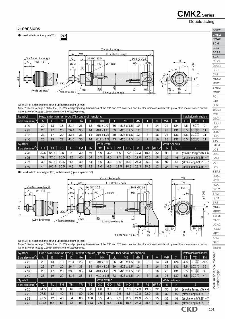
Symbol
Bore size (mm)
Head side trunnion type (TB) basic dimensions Installation dimensions
With switch
9
11
11
11
TE
4.5
5.5
5.5
5.5
TB
124
131
131
137
X
24
23
23
23
WF
14
16
16
16
V
5
6
6
7
T
10
12
12
14
MM
M18 x 1.5
M26 x 1.5
M26 x 1.5
M26 x 1.5
MB
66
69
69
73
LL
M8 x 1.0
M10 x 1.25
M10 x 1.25
M12 x 1.5
KK
26
35
35
35
HA
12
14
14
14
K
21.4
26.4
33.6
41.6
D
18
20
20
22
C
13
17
17
19
B
20
23
23
25
A
M18 x 1.5
M26 x 1.5
M26 x 1.5
M26 x 1.5
MB
66
69
69
73
LL
M8 x 1.0
M10 x 1.25
M10 x 1.25
M12 x 1.5
KK
26
35
35
35
HA
12
14
14
14
K
21.4
26.4
33.6
41.6
D
18
20
20
22
C
13
17
17
19
B
20
23
23
25
A
4.0
5.5
5.5
7.0
GC
3.0
4.5
4.5
6.5
GD
8.0
9.5
9.5
11.5
RD
7.0
8.5
8.5
10.5
HD
17.3
19.8
24.3
28.3
P
19.5
22.0
25.5
29.5
P1
22
18
15
12
(P )°
46
64
64
72
TN
30
40
40
53
TM
8
12
12
9.5
TL
9.5
10.5
10.5
10.5
TK
94.5
97.5
97.5
101.5
TJ
29.5
39
39
44
TH
20
25
32
40
Symbol
Bore size (mm)
20
25
32
40
8
10
10
10
TD-0.040-0.076
-0.040-0.076
-0.040-0.076
-0.040-0.076
Note 1: For dimensions, round up decimal point or less.Note 2: Refer to page 188 for the HD, RD, and projecting dimensions of the T1* and T8* switches and 2-color indicator switch with preventive maintenance output.Note 3: Refer to page 190 for dimensions of accessories.
Symbol
Bore size (mm)
Head side trunnion type (TB) with bracket (option symbol B2) basic dimensions Installation dimensions
With switch
29.5
39
39
44
TH
4.5
5.5
5.5
5.5
TB
124
131
131
137
X
24
23
23
23
WF
14
16
16
16
V
5
6
6
7
T
10
12
12
14
MM
4.0
5.5
5.5
7.0
GC
3.0
4.5
4.5
6.5
GD
8.0
9.5
9.5
11.5
RD
7.0
8.5
8.5
10.5
HD
17.3
19.8
24.3
28.3
P
19.5
22.0
25.5
29.5
P1
22
18
15
12
(P )°
90
100
100
113
TS
70
80
80
93
TR
46
64
64
72
TN
30
40
40
53
TM
8
12
12
9.5
TL
94.5
97.5
97.5
101.5
TJ
20
25
32
40
Symbol
Bore size (mm)
20
25
32
40
8
10
10
10
TD-0.040-0.076
-0.040-0.076
-0.040-0.076
-0.040-0.076
Head side trunnion type (TB)
Note 1: For dimensions, round up decimal point or less.Note 2: Refer to page 188 for the HD, RD, and projecting dimensions of the T1* and T8* switches and 2-color indicator switch with preventive maintenance output.Note 3: Refer to page 190 for dimensions of accessories.
Head side trunnion type (TB) with bracket (option symbol B2)
Dimensions
With bellows
30
32
32
34
b
30
46
46
46
d
(stroke length/3) + 6
(stroke length/3.25) + 7
(stroke length/3.25) + 7
(stroke length/3.25) + 7
With bellows
30
32
32
34
b
30
46
46
46
d
(stroke length/3) + 6
(stroke length/3.25) + 7
(stroke length/3.25) + 7
(stroke length/3.25) + 7
WF +X + + stroke length
d
Ab
TNTL TM
TH
TD
d9
HA
P1
P
8
(P
)
TJ + stroke length TKTEMB
K
D
HDRD
1010
MM
LL + stroke length V
8
16GD30.5
WFA
C V GC 30.516
8
T
X + stroke length
Width across flats B
KK
2-Rc1/8
WF +X + + stroke length
d
Ab
TSTR
10 20 20
TN
HA
TD
d9T
H
TL TM
P1
(P
)
8
P
3.2
4-oval hole 7 x 11 557.540
20
TJ + stroke length
T
8
16 30.5GCVC
A WF
30.5 GD 16
8
VLL + stroke length
K
10 10
RD HD
D
X + stroke length
50
10
Width across flats B
KK
MM 2-Rc1/8
MB
(with bellows)
(with bellows)
TB
TB
CMK2 Series
Double acting