Chapter 36 › ~taozhou › bbb › 36.pdf · Chapter 36 1. (a) The condition for a minimum in a...
38
1413 Chapter 36 1. (a) The condition for a minimum in a single-slit diffraction pattern is given by a sin θ = mλ, where a is the slit width, λ is the wavelength, and m is an integer. For λ = λ a and m = 1, the angle θ is the same as for λ = λ b and m = 2. Thus, λ a = 2λ b = 2(350 nm) = 700 nm. (b) Let m a be the integer associated with a minimum in the pattern produced by light with wavelength λ a , and let m b be the integer associated with a minimum in the pattern produced by light with wavelength λ b . A minimum in one pattern coincides with a minimum in the other if they occur at the same angle. This means m a λ a = m b λ b . Since λ a = 2λ b , the minima coincide if 2m a = m b . Consequently, every other minimum of the λ b pattern coincides with a minimum of the λ a pattern. With m a =2, we have m b = 4. (c) With m a =3, we have m b = 6. 2. (a) θ = sin –1 (1.50 cm/2.00 m) = 0.430°. (b) For the mth diffraction minimum a sin θ = mλ. We solve for the slit width: a m = = ° = λ sin sin . . . θ 2 441 0 430 0118 nm mm b g 3. The condition for a minimum of a single-slit diffraction pattern is a m sin θ = λ where a is the slit width, λ is the wavelength, and m is an integer. The angle θ is measured from the forward direction, so for the situation described in the problem, it is 0.60° for m = 1. Thus, a m = = × ° = × − − λ sin sin . . . θ 633 10 0 60 6 04 10 9 5 m m 4. From Eq. 36-3, a m = = ° = sin sin . . . θ 1 45 0 141
Transcript of Chapter 36 › ~taozhou › bbb › 36.pdf · Chapter 36 1. (a) The condition for a minimum in a...
1413
Chapter 36 1. (a) The condition for a minimum in a single-slit diffraction pattern is given by
a sin θ = mλ, where a is the slit width, λ is the wavelength, and m is an integer. For λ = λa and m = 1, the angle θ is the same as for λ = λb and m = 2. Thus,
λa = 2λb = 2(350 nm) = 700 nm. (b) Let ma be the integer associated with a minimum in the pattern produced by light with wavelength λa, and let mb be the integer associated with a minimum in the pattern produced by light with wavelength λb. A minimum in one pattern coincides with a minimum in the other if they occur at the same angle. This means maλa = mbλb. Since λa = 2λb, the minima coincide if 2ma = mb. Consequently, every other minimum of the λb pattern coincides with a minimum of the λa pattern. With ma =2, we have mb = 4. (c) With ma =3, we have mb = 6. 2. (a) θ = sin–1 (1.50 cm/2.00 m) = 0.430°. (b) For the mth diffraction minimum a sin θ = mλ. We solve for the slit width:
a m= =
°=
λsin sin .
. .θ
2 4410 430
0118nm
mmb g
3. The condition for a minimum of a single-slit diffraction pattern is
a msinθ = λ where a is the slit width, λ is the wavelength, and m is an integer. The angle θ is measured from the forward direction, so for the situation described in the problem, it is 0.60° for m = 1. Thus,
a m= =
×°
= ×−
−λsin sin .
. .θ
633 100 60
6 04 109
5m m
4. From Eq. 36-3,
a m= =
°=
sin sin .. .
θ1450
141

CHAPTER 36 1414
5. (a) A plane wave is incident on the lens so it is brought to focus in the focal plane of the lens, a distance of 70 cm from the lens. (b) Waves leaving the lens at an angle θ to the forward direction interfere to produce an intensity minimum if a sin θ = mλ, where a is the slit width, λ is the wavelength, and m is an integer. The distance on the screen from the center of the pattern to the minimum is given by y = D tan θ, where D is the distance from the lens to the screen. For the conditions of this problem,
sin.
. .θ = =×
×= ×
−
−−m
aλ 1 590 10
0 40 101475 10
9
33bgc hm
m
This means θ = 1.475 × 10⁻³ rad and
y = (0.70 m) tan(1.475 × 10⁻³ rad) = 1.0 × 10⁻³ m. 6. (a) Eq. 36-3 and Eq. 36-12 imply smaller angles for diffraction for smaller wavelengths. This suggests that diffraction effects in general would decrease. (b) Using Eq. 36-3 with m = 1 and solving for 2θ (the angular width of the central diffraction maximum), we find
2 2 2 0 505 0
111 1θ = FHGIKJ=FHG
IKJ= °− −sin sin .
..
am
m
(c) A similar calculation yields 0.23° for λ = 0.010 m. 7. (a) We use Eq. 36-3 to calculate the separation between the first (m1 = 1) and fifth
2( 5)m = minima:
∆ ∆ ∆ ∆y D D ma
Da
m Da
m m= = FHG IKJ= = −sin .θ λ λ λ2 1b g
Solving for the slit width, we obtain
aD m m
y=
−=
× −=
−λ 2 16400 550 10 5 1
0 352 5b g b gc hb g
∆
mm mmmm
mm.
. .
(b) For m = 1,
sin.
. .θ = =×
= ×−
−maλ 1 550 10
2 52 2 10
64bgc hmm
mm
The angle is θ = sin–1 (2.2 × 10⁻⁴) = 2.2 × 10⁻⁴ rad.

1415
8. From y = mλL/a we get
(632.8nm)(2.60) [10 ( 10)] 24.0 mm .1.37 mm
m L Ly ma aλ λ ∆ = ∆ = ∆ = − − =
9. The condition for a minimum of intensity in a single-slit diffraction pattern is a sin θ = mλ, where a is the slit width, λ is the wavelength, and m is an integer. To find the angular position of the first minimum to one side of the central maximum, we set m = 1:
θ 11 1
9
34589 10
100 10589 10= FHGIKJ=
××
FHG
IKJ= ×− −
−
−−sin sin
.. .λ
amm
rad
If D is the distance from the slit to the screen, the distance on the screen from the center of the pattern to the minimum is
y D1 14 3300 589 10 1767 10= = × = ×− −tan . tan . . .θ m rad mb g c h
To find the second minimum, we set m = 2:
θ 21
9
33
2 589 10100 10
1178 10=×
×
FHG
IKJ= ×−
−
−−sin
.. .
mm
radc h
The distance from the center of the pattern to this second minimum is
y2 = D tan θ2 = (3.00 m) tan (1.178 × 10⁻³ rad) = 3.534 × 10⁻³ m. The separation of the two minima is
∆y = y2 – y1 = 3.534 mm – 1.767 mm = 1.77 mm. 10. Let the first minimum be a distance y from the central axis which is perpendicular to the speaker. Then
sinθ = + = =y D y m a a2 2 1 2c h λ λ (for m = 1). Therefore,
( ) ( ) ( )( ) ( )2 2 2
100m 41.2m .1 1 0.300m 3000Hz 343m s 1s
D Dya af v
= = = =λ − − −
11. (a) θ = sin–1 (0.011 m/3.5 m) = 0.18°.

CHAPTER 36 1416
(b) We use Eq. 36-6:
α θ= FHGIKJ =°
×=−
πλ
πa sin. sin .
. .0 025 018538 10
0 466
mmmm
radb g
(c) Making sure our calculator is in radian mode, Eq. 36-5 yields
IIm
θ αα
bg= FHG IKJ=
sin . .2
0 93
12. We will make use of arctangents and sines in our solution, even though they can be “shortcut” somewhat since the angles are small enough to justify the use of the small angle approximation. (a) Given y/D = 15/300 (both expressed here in centimeters), then θ = tan−1(y/D) = 2.86°. Use of Eq. 36-6 (with a = 6000 nm and λ = 500 nm) leads to
( )6000nm sin 2.86sin 1.883rad .500nm
a θαπ °π
= = =λ
Thus, 2sin 0.256 .p
m
II
αα
= =
(b) Consider Eq. 36-3 with “continuously variable” m (of course, m should be an integer for diffraction minima, but for the moment we will solve for it as if it could be any real number):
sin (6000 nm)sin 2.86 0.60500 nm
am θλ
°= = ≈ .
which suggests that the angle takes us to a point between the central maximum (θcentr = 0) and the first minimum (which corresponds to m = 1 in Eq. 36-3). 13. We note that 1 nm = 1 ×10⁻⁹ m = 1 ×10⁻⁶ mm. From Eq. 36-4,
∆ ∆φ θ= FHGIKJ =×
FHG
IKJFHG IKJ ° =−
2 2589 10
0102
30 266 76
πλ
πx sin . sin . .b gmm
mm rad
This is equivalent to 266.7 rad – 84π = 2.8 rad = 160°. 14. (a) The slope of the plotted line is 12, and we see from Eq. 36-6 that this slope should correspond to
1417
12 12(610 nm)12 2330 nm 2.33 ma aπ λ µλ π π
= ⇒ = = = ≈
(b) Consider Eq. 36-3 with “continuously variable” m (of course, m should be an integer for diffraction minima, but for the moment we will solve for it as if it could be any real number):
( )max max
2330 nmsin 3.82610 nm
a am θλ λ
= = = ≈
which suggests that, on each side of the central maximum (θcentr = 0), there are three minima; considering both sides then implies there are six minima in the pattern. (c) Setting m = 1 in Eq. 36-3 and solving for θ yields 15.2°. (d) Setting m = 3 in Eq. 36-3 and solving for θ yields 51.8°. 15. (a) The intensity for a single-slit diffraction pattern is given by
I Im=sin2
2
αα
where α is described in the text (see Eq. 36-6). To locate the extrema, we set the derivative of I with respect to α equal to zero and solve for α. The derivative is
dId
Imαα
αα α α= −2 3
sin cos sin .b g
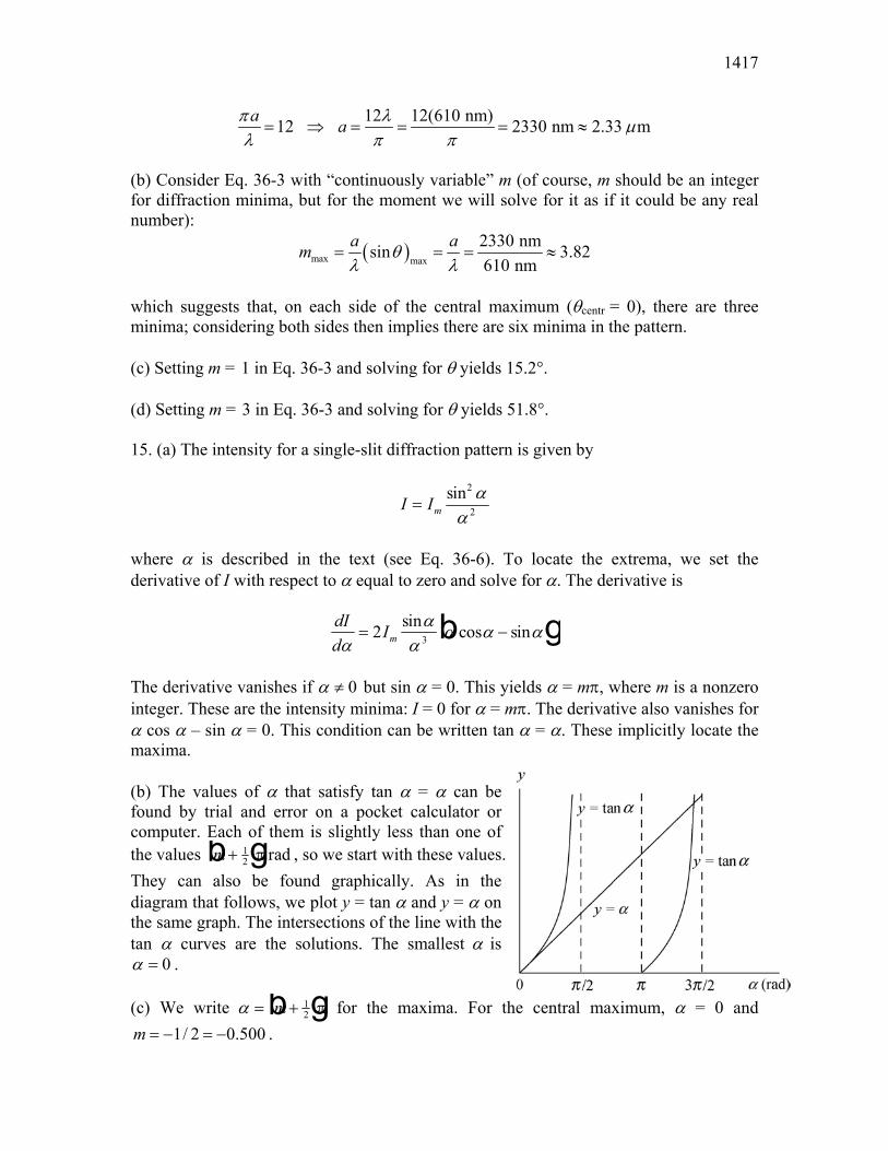
The derivative vanishes if 0α ≠ but sin α = 0. This yields α = mπ, where m is a nonzero integer. These are the intensity minima: I = 0 for α = mπ. The derivative also vanishes for α cos α – sin α = 0. This condition can be written tan α = α. These implicitly locate the maxima. (b) The values of α that satisfy tan α = α can be found by trial and error on a pocket calculator or computer. Each of them is slightly less than one of the values m + 1
2b gπ rad , so we start with these values. They can also be found graphically. As in the diagram that follows, we plot y = tan α and y = α on the same graph. The intersections of the line with the tan α curves are the solutions. The smallest α is
0α = . (c) We write α = +m 1
2b gπ for the maxima. For the central maximum, α = 0 and 1/ 2 0.500m = − = − .

CHAPTER 36 1418
(d) The next one can be found to be α = 4.493 rad. (e) For α = 4.4934, m = 0.930. (f) The next one can be found to be α = 7.725 rad. (g) For α = 7.7252, m = 1.96. 16. Consider Huygens’ explanation of diffraction phenomena. When A is in place only the Huygens’ wavelets that pass through the hole get to point P. Suppose they produce a resultant electric field EA. When B is in place, the light that was blocked by A gets to P and the light that passed through the hole in A is blocked. Suppose the electric field at P is now
ρEB . The sum
ρ ρE EA B+ is the resultant of all waves that get to P when neither A nor
B are present. Since P is in the geometric shadow, this is zero. Thus ρ ρE EA B= − , and since
the intensity is proportional to the square of the electric field, the intensity at P is the same when A is present as when B is present. 17. (a) The intensity for a single-slit diffraction pattern is given by
I Im=sin2
2
αα
where α = (πa/λ) sin θ, a is the slit width and λ is the wavelength. The angle θ is measured from the forward direction. We require I = Im/2, so
sin .2 212
α α=
(b) We evaluate sin2 α and α 2 2 for α = 1.39 rad and compare the results. To be sure that 1.39 rad is closer to the correct value for α than any other value with three significant digits, we could also try 1.385 rad and 1.395 rad. (c) Since α = (πa/λ) sin θ,
θ α= FHGIKJ−sin .1 λ
πa
Now α/π = 1.39/π = 0.442, so
θ = FHG IKJ−sin . .1 0 442λa
The angular separation of the two points of half intensity, one on either side of the center of the diffraction pattern, is

1419
∆θ θ= = FHG IKJ−2 2 0 4421sin . .λa
(d) For a/λ = 1.0,
( )12sin 0.442 1.0 0.916 rad 52.5θ −∆ = = = ° . (e) For a/λ = 5.0,
( )12sin 0.442 5.0 0.177 rad 10.1θ −∆ = = = ° . (f) For a/λ = 10, ∆θ = = = °−2 0 442 10 0 0884 5061sin . . . .b g rad 18. Using the same notation found in Sample Problem 36-3,
DL d
= =θ R 122.
where we will assume a “typical” wavelength for visible light: λ ≈ 550 × 10–9 m. (a) With L = 400 × 103 m and D = 0.85 m, the above relation leads to d = 0.32 m. (b) Now with D = 0.10 m, the above relation leads to d = 2.7 m. (c) The military satellites do not use Hubble Telescope-sized apertures. A great deal of very sophisticated optical filtering and digital signal processing techniques go into the final product, for which there is not space for us to describe here. 19. Using the notation of Sample Problem 36-3,
2 36 3
9R
(5.0 10 m)(4.0 10 m) 1.6 10 m 1.6 10 km .1.22 / 1.22(0.10 10 m)
D DLdθ
− −
−
× ×= = = = × = ×
λ ×
20. (a) Using the notation of Sample Problem 36-3, the minimum separation is
D L Ld
= = FHG IKJ=× ×
≈−
θ R
m mm
m.122 400 10 122 550 100 005
503 9. .
.c hb gc h
b g
(b) The Rayleigh criterion suggests that the astronaut will not be able to discern the Great Wall (see the result of part (a)).

CHAPTER 36 1420
(c) The signs of intelligent life would probably be, at most, ambiguous on the sunlit half of the planet. However, while passing over the half of the planet on the opposite side from the Sun, the astronaut would be able to notice the effects of artificial lighting. 21. (a) We use the Rayleigh criteria. Thus, the angular separation (in radians) of the sources must be at least θR = 1.22λ/d, where λ is the wavelength and d is the diameter of the aperture. For the headlights of this problem,
( )94
R 3
1.22 550 10 m1.34 10 rad,
5.0 10 mθ
−−
−
×= = ×
×
or 41.3 10 rad−× , in two significant figures. (b) If L is the distance from the headlights to the eye when the headlights are just resolvable and D is the separation of the headlights, then D = LθR, where the small angle approximation is made. This is valid for θR in radians. Thus,
44
R
1.4m 1.0 10 m 10km .1.34 10 rad
DLθ −= = = × =
×
22. We use Eq. 36-12 with θ = 2.5°/2 = 1.25°. Thus,
d = =°
=122 122 550
12531.
sin.
sin ..λ
θµ
nmmb g
23. Using the notation of Sample Problem 36-3, the minimum separation is
( ) ( )( )98
R
1.22 550 10 m1.22 3.82 10 m 50m .
5.1mD L L
dθ
−×λ = = = × =
24. Using the notation of Sample Problem 36-3, the minimum separation is
( ) ( )( )23
R
1.22 1.6 10 m1.22 6.2 10 m 53m .2.3m
D L Ld
θ−×λ = = = × =
25. (a) We use the Rayleigh criteria. If L is the distance from the observer to the objects, then the smallest separation D they can have and still be resolvable is D = LθR, where θR is measured in radians. The small angle approximation is made. Thus,
D Ld
= =× ×
×= × ×
−
−
122 122 8 0 10 550 1050 10
11 1010 9
37. . .
.. .λ m m
mm = 1.1 10 km4c hc h

1421
This distance is greater than the diameter of Mars; therefore, one part of the planet’s surface cannot be resolved from another part. (b) Now d = 5.1 m and
D =× ×
= × =−122 8 0 10 550 10
5111 10 11
10 94
. ..
. .m m
mm km
c hc h
26. Using the notation of Sample Problem 36-3, the maximum distance is
( )( )( )3 3
9R
5.0 10 m 4.0 10 m30m .
1.22 1.22 550 10 mD DL
dθ
− −
−
× ×= = = =
λ ×
27. (a) Using the notation of Sample Problem 36-3,
L Dd
=λ /122
2 50 10122 650 10
0196 3
9.(
. (.=
× ××
=− −
−
m)(1.5 10 m)m)
m .
(b) The wavelength of the blue light is shorter so Lmax ∝ λ–1 will be larger. 28. From Fig. 36-44(a), we find the diameter D′ on the retina to be
2.00 cm(2.00 mm) 0.0889 mm45.0 cm
LD DL′
′ = = = .
Next, using Fig. 36-44(b), the angle from the axis is
1 1/ 2 0.0889 mm / 2tan tan 0.4246.00 mm
Dx
θ − −′ = = = °
.
Since the angle corresponds to the first minimum in the diffraction pattern, we have sin 1.22 / dθ λ= , where λ is the wavelength and d is the diameter of the defect. With
550 nm,λ = we obtain
51.22 1.22(550 nm) 9.06 10 m 91 msin sin(0.424 )
d λ µθ
−= = = × ≈°
.
29. (a) The first minimum in the diffraction pattern is at an angular position θ, measured from the center of the pattern, such that sin θ = 1.22λ/d, where λ is the wavelength and d is the diameter of the antenna. If f is the frequency, then the wavelength is

CHAPTER 36 1422
λ =cf
=××
= × −300 10220 10
136 108
93. . .m s
Hzm
Thus,
θ = FHG IKJ=×
×
FHG
IKJ= ×− −
−
−−sin . sin
. ..
. .1 13
23122 122 136 10
55 0 103 02 10λ
dm
mrad
c h
The angular width of the central maximum is twice this, or 6.04 × 10⁻³ rad (0.346°). (b) Now λ = 1.6 cm and d = 2.3 m, so
θ =×F
HGIKJ= ×−
−−sin
. ..
. .12
3122 16 10
2 38 5 10
mm
radc h
The angular width of the central maximum is 1.7 × 10⁻² rad (or 0.97°). 30. (a) We use Eq. 36-12:
( ) ( )( )( )( )
1 1 13
1.22 1.22 1450 m s1.22sin sin sin 6.8 .25 10 Hz 0.60 m
sv fd d
λθ − − − = = = = ° ×
(b) Now f = 1.0 × 10³ Hz so
122 122 14500 60
2 9 1. ..
. .d
=×
= >b gb g
c hb gm s
1.0 10 Hz m3
Since sin θ cannot exceed 1 there is no minimum. 31. Eq. 36-14 gives the Rayleigh angle (in radians):
1.22R
Dd L
λθ = = where the rationale behind the second equality is given in Sample Problem 36-3. (a) We are asked to solve for D and are given λ = 1.40 × 10⁻⁹ m, d = 0.200 × 10⁻³ m, and
32000 10 mL = × . Consequently, we obtain D = 17.1 m. (b) Intensity is power over area (with the area assumed spherical in this case, which means it is proportional to radius-squared), so the ratio of intensities is given by the square of a ratio of distances: (d/D)2 = 1.37 × 10⁻¹⁰.

1423
32. Eq. 36-14 gives θR = 1.22λ/d, where in our case θR ≈ D/L, with D = 60 µm being the size of the object your eyes must resolve, and L being the maximum viewing distance in question. If d = 3.00 mm = 3000 µm is the diameter of your pupil, then
L Dd= = = × =
12260 3000
122 0552 7 10 275
. . .. .
λµ µ
µµ
m mm
m cmb gb gb g
33. (a) Using Eq. 36-14, the angular separation is
( )( )97
R
1.22 550 10 m1.22 8.8 10 rad .0.76md
θ−
−×λ
= = = ×
(b) Using the notation of Sample Problem 36-3, the distance between the stars is
( )( )( )( )( )
127
R
10ly 9.46 10 km ly 0.188.4 10 km .
3600 180D Lθ
× π= = = ×
(c) The diameter of the first dark ring is
( )( )( )( )( )
5R
2 0.18 14m2 2.5 10 m 0.025mm .
3600 180d Lθ −π
= = = × =
34. (a) Since θ = 1.22λ/d, the larger the wavelength the larger the radius of the first minimum (and second maximum, etc). Therefore, the white pattern is outlined by red lights (with longer wavelength than blue lights). (b) The diameter of a water drop is
d = ≈×
° °= ×
−−122 122 7 10
15 050 213 10
74. .
. .. .λ
π 180θm
mc h
b gb g
35. In a manner similar to that discussed in Sample Problem 36-5, we find the number is 2(d/a) – 1 = 2(2a/a) – 1 = 3. 36. Following the method of Sample Problem 36-5, we find
3
6
0.30 10 m 6.5246 10 m
da
−
−
×= =
×
which we interpret to mean that the first diffraction minimum occurs slightly farther “out” than the m = 6 interference maximum. This implies that the central diffraction envelope includes the central (m = 0) interference maximum as well as six interference

CHAPTER 36 1424
maxima on each side of it. Therefore, there are 6 + 1 + 6 = 13 bright fringes (interference maxima) in the central diffraction envelope. 37. Bright interference fringes occur at angles θ given by d sin θ = mλ, where m is an integer. For the slits of this problem, we have d = 11a/2, so
a sin θ = 2mλ/11 (see Sample Problem 36-5). The first minimum of the diffraction pattern occurs at the angle θ1 given by a sin θ1 = λ, and the second occurs at the angle θ2 given by a sin θ2 = 2λ, where a is the slit width. We should count the values of m for which θ1 < θ < θ2, or, equivalently, the values of m for which sin θ1 < sin θ < sin θ2. This means 1 < (2m/11) < 2. The values are m = 6, 7, 8, 9, and 10. There are five bright fringes in all. 38. The angular location of the mth bright fringe is given by d sin θ = mλ, so the linear separation between two adjacent fringes is
∆ ∆ ∆ ∆y D Dd
Dd
m Dd
m= = FHG IKJ= =sin .θb g λ λ λ
39. (a) The angular positions θ of the bright interference fringes are given by d sin θ = mλ, where d is the slit separation, λ is the wavelength, and m is an integer. The first diffraction minimum occurs at the angle θ1 given by a sin θ1 = λ, where a is the slit width. The diffraction peak extends from –θ1 to +θ1, so we should count the number of values of m for which –θ1 < θ < +θ1, or, equivalently, the number of values of m for which – sin θ1 < sin θ < + sin θ1. This means – 1/a < m/d < 1/a or –d/a < m < +d/a. Now
d/a = (0.150 × 10⁻³ m)/(30.0 × 10–6 m) = 5.00, so the values of m are m = –4, –3, –2, –1, 0, +1, +2, +3, and +4. There are 9 fringes. (b) The intensity at the screen is given by
I Im= FHG IKJcos sin22
β αα
c h
where α = (πa/λ) sin θ, β = (πd/λ) sin θ, and Im is the intensity at the center of the pattern. For the third bright interference fringe, d sin θ = 3λ, so β = 3π rad and cos2 β = 1. Similarly, α = 3πa/d = 3π/5.00 = 0.600π rad and
sin sin ..
. .αα
FHG IKJ= FHG IKJ=2 20 600
0 6000 255π
π
The intensity ratio is I/Im = 0.255.

1425
40. (a) In a manner similar to that discussed in Sample Problem 36-5, we find the ratio should be d/a = 4. Our reasoning is, briefly, as follows: we let the location of the fourth bright fringe coincide with the first minimum of diffraction pattern, and then set sin θ = 4λ/d = λ/a (so d = 4a). (b) Any bright fringe which happens to be at the same location with a diffraction minimum will vanish. Thus, if we let
1 2 1sin4
m m md a aλ λ λθ = = = ,
or m1 = 4m2 where m2 1 2 3= , , ,Λ . The fringes missing are the 4th, 8th, 12th, and so on. Hence, every fourth fringe is missing. 41. (a) The first minimum of the diffraction pattern is at 5.00°, so
a = =°
=λ
sin.sin .
. .θ
µ µ0 440500
505m m
(b) Since the fourth bright fringe is missing, d = 4a = 4(5.05 µm) = 20.2 µm. (c) For the m = 1 bright fringe,
α θ µµ
= =°
=π
λπa sin . sin .
.. .
505 1250 440
0 787m
mradb g
Consequently, the intensity of the m = 1 fringe is
I Im= FHG IKJ= FHG IKJ=sin . sin .
.. ,α
α
22
227 0 0 787
0 78757mW cm rad mW cmd i
which agrees with Fig. 36-47. Similarly for m = 2, the intensity is I = 2.9 mW/cm2, also in agreement with Fig. 36-47. 42. (a) We note that the slope of the graph is 80, and that Eq. 36-20 implies that the slope should correspond to
80 80(435 nm)80 11077 nm 11.1 md dπ λ µλ π π
= ⇒ = = = ≈ .
(b) Consider Eq. 36-25 with “continuously variable” m (of course, m should be an integer for interference maxima, but for the moment we will solve for it as if it could be any real number):

CHAPTER 36 1426
( )max max
11077 nmsin 25.5435 nm
d dm θλ λ
= = = ≈
which indicates (on one side of the interference pattern) there are 25 bright fringes. Thus on the other side there are also 25 bright fringes. Including the one in the middle, then, means there are a total of 51 maxima in the interference pattern (assuming, as the problem remarks, that none of the interference maxima have been eliminated by diffraction minima). (c) Clearly, the maximum closest to the axis is the middle fringe at θ = 0°. (d) If we set m = 25 in Eq. 36-25, we find
1 1 (25)(435 nm)sin sin sin 79.011077 nm
mm ddλλ θ θ − − = ⇒ = = = °
43. We will make use of arctangents and sines in our solution, even though they can be “shortcut” somewhat since the angles are [almost] small enough to justify the use of the small angle approximation. (a) Given y/D = (0.700 m)/(4.00 m), then
1 1 0.700 mtan tan 9.93 0.173 rad4.00 m
yD
θ − − = = = ° =
.
Eq. 36-20 then gives
( )24.0 m sin 9.93sin 21.66 rad .0.600 m
d µθβµ
π °π= = =
λ
Thus, use of Eq. 36-21 (with a = 12 µm and λ = 0.60 µm) leads to
( )12.0 m sin 9.93sin 10.83 rad .0.600 m
a µθαµ
π °π= = =
λ
Thus,
( )2 2
22sin sin10.83rad(cos ) cos 21.66 rad 0.0074310.83m
II
α βα
= = =
.
(b) Consider Eq. 36-25 with “continuously variable” m (of course, m should be an integer for interference maxima, but for the moment we will solve for it as if it could be any real number):
( )24.0 m sin 9.93sin 6.90.600 m
dmµθ
µ°
= = ≈λ

1427
which suggests that the angle takes us to a point between the sixth minimum (which would have m = 6.5) and the seventh maximum (which corresponds to m = 7). (c) Similarly, consider Eq. 36-3 with “continuously variable” m (of course, m should be an integer for diffraction minima, but for the moment we will solve for it as if it could be any real number):
( )12.0 m sin 9.93sin 3.40.600 m
amµθ
µ°
= = ≈λ
which suggests that the angle takes us to a point between the third diffraction minimum (m = 3) and the fourth one (m = 4). The maxima (in the smaller peaks of the diffraction pattern) are not exactly midway between the minima; their location would make use of mathematics not covered in the prerequisites of the usual sophomore-level physics course. 44. The angular location of the mth order diffraction maximum is given by mλ = d sin θ. To be able to observe the fifth-order maximum, we must let sin θ|m=5 = 5λ/d < 1, or
λ < = =d5
1005
635. .nm / 315 nm
Therefore, the longest wavelength that can be used is λ = 635 nm. 45. The ruling separation is
d = 1/(400 mm–1) = 2.5 × 10⁻³ mm. Diffraction lines occur at angles θ such that d sin θ = mλ, where λ is the wavelength and m is an integer. Notice that for a given order, the line associated with a long wavelength is produced at a greater angle than the line associated with a shorter wavelength. We take λ to be the longest wavelength in the visible spectrum (700 nm) and find the greatest integer value of m such that θ is less than 90°. That is, find the greatest integer value of m for which mλ < d. Since
6
9
2.5 10 m 3.57700 10 m
d −
−
×= ≈
λ ×,
that value is m = 3. There are three complete orders on each side of the m = 0 order. The second and third orders overlap. 46. We use Eq. 36-25 for diffraction maxima: d sin θ = mλ. In our case, since the angle between the m = 1 and m = –1 maxima is 26°, the angle θ corresponding to m = 1 is θ = 26°/2 = 13°. We solve for the grating spacing:

CHAPTER 36 1428
( )( )1 550nm2.4 m 2 m.
sin sin13md µ µ
θλ
= = = š
47. The distance between adjacent rulings is
d = 20.0 mm/6000 = 0.00333 mm = 3.33 µm. (a) Let ( )sin 0, 1, 2,d m mθ = λ = ± ± K . Since |m|λ/d > 1 for |m| ≥ 6, the largest value of θ corresponds to | m | = 5, which yields
( )1 1 5(0.589 m)sin | | / sin 62.13.33 m
m d µθµ
− − = λ = = °
(b) The second largest value of θ corresponds to |m| = 4, which yields
( )1 1 4(0.589 m)sin | | / sin 45.03.33 m
m d µθµ
− − = λ = = °
(c) The third largest value of θ corresponds to | m | = 3, which yields
( )1 1 3(0.589 m)sin | | / sin 32.03.33 m
m d µθµ
− − = λ = = °
48. We note that the central diffraction envelope contains the central bright interference fringe (corresponding to m = 0 in Eq. 36-25) plus ten on either side of it. Since the eleventh order bright interference fringe is not seen in the central envelope, then we conclude the first diffraction minimum (satisfying sinθ = λ/a) coincides with the m = 11 instantiation of Eq. 36-25:
d = mλ
sin θ = 11 λ λ/a = 11 a .
Thus, the ratio d/a is equal to 11. 49. (a) Since d = (1.00 mm)/180 = 0.0056 mm, we write Eq. 36-25 as
1 1sin sin (180)(2)md
θ − −λ = = λ
where λ1 = × −4 10 4 mm and λ2 = × −5 10 4 mm. Thus, ∆θ θ θ= − = °2 1 21. . (b) Use of Eq. 36-25 for each wavelength leads to the condition
1429
m m1 1 2 2λ λ= for which the smallest possible choices are m1 = 5 and m2 = 4. Returning to Eq. 36-25, then, we find
( )4
1 1 11 1 10 mm)sin sin sin 0.36 21 .0.0056 mm
md
θ−
− − − λ 5(4.0× = = = = °
(c) There are no refraction angles greater than 90°, so we can solve for “mmax” (realizing it might not be an integer):
max 42 2
sin 90 0.0056 mm 1110 mm
d dm −
°= = = ≈
λ λ 5.0×
where we have rounded down. There are no values of m (for light of wavelength λ2) greater than m = 11. 50. (a) For the maximum with the greatest value of m (= M) we have Mλ = a sin θ < d, so M < d/λ = 900 nm/600 nm = 1.5, or M = 1. Thus three maxima can be seen, with m = 0, ±1. (b) From Eq. 36-28, we obtain
∆θ λθ
θθ
θ λhw
nm900 nm
= = = = FHGIKJLNM
OQP
=FHG
IKJ
LNM
OQP= °
−
−
N dd
N d N N dcossincos
tan tan sin
tan sin . .
1
11000
600 0 051
1
1
51. (a) Maxima of a diffraction grating pattern occur at angles θ given by d sin θ = mλ, where d is the slit separation, λ is the wavelength, and m is an integer. The two lines are adjacent, so their order numbers differ by unity. Let m be the order number for the line with sin θ = 0.2 and m + 1 be the order number for the line with sin θ = 0.3. Then, 0.2d = mλ and 0.3d = (m + 1)λ. We subtract the first equation from the second to obtain 0.1d = λ, or
d = λ/0.1 = (600 × 10–9m)/0.1 = 6.0 × 10⁻⁶ m. (b) Minima of the single-slit diffraction pattern occur at angles θ given by a sin θ = mλ, where a is the slit width. Since the fourth-order interference maximum is missing, it must fall at one of these angles. If a is the smallest slit width for which this order is missing, the angle must be given by a sin θ = λ. It is also given by d sin θ = 4λ, so
a = d/4 = (6.0 × 10⁻⁶ m)/4 = 1.5 × 10⁻⁶ m.

CHAPTER 36 1430
(c) First, we set θ = 90° and find the largest value of m for which mλ < d sin θ. This is the highest order that is diffracted toward the screen. The condition is the same as m < d/λ and since
d/λ = (6.0 × 10⁻⁶ m)/(600 × 10–9 m) = 10.0, the highest order seen is the m = 9 order. The fourth and eighth orders are missing, so the observable orders are m = 0, 1, 2, 3, 5, 6, 7, and 9. Thus, the largest value of the order number is m = 9. (d) Using the result obtained in (c), the second largest value of the order number is m = 7. (e) Similarly, the third largest value of the order number is m = 6. 52. We use Eq. 36-25. For m = ±1
λ θ µ= =
± °±
=d
msin ( .173
1523m)sin( 17.6 ) nm,
and for m = ±2,
λ µ=
± °±
=( .173
2524m) sin( 37.3 ) nm.
Similarly, we may compute the values of λ corresponding to the angles for m = ±3. The average value of these λ’s is 523 nm. 53. The angular positions of the first-order diffraction lines are given by d sin θ = λ. Let λ1 be the shorter wavelength (430 nm) and θ be the angular position of the line associated with it. Let λ2 be the longer wavelength (680 nm), and let θ + ∆θ be the angular position of the line associated with it. Here ∆θ = 20°. Then,
1 2sin , sin( )d dλ θ λ θ θ= = + ∆ . We write
sin (θ + ∆θ) as sin θ cos ∆θ + cos θ sin ∆θ, then use the equation for the first line to replace sin θ with λ1/d, and cos θ with
1 12 2− λ d . After multiplying by d, we obtain
λ θ λ θ λ1
212
2cos sin .∆ ∆+ − =d Solving for d, we find
1431
d =− +
=− ° + °
°= = × −
λ λ θ λ θθ
2 12
12
2
2 2
2
4
680 430 20 430 2020
914 9 14 10
cos sinsin
cos sinsin
.
∆ ∆∆
b g b g
b gb g b g nm nm nm
nm mm.
There are 1/d = 1/(9.14 × 10–4 mm) = 1.09 × 10³ rulings per mm. 54. We are given the “number of lines per millimeter” (which is a common way to express 1/d for diffraction gratings); thus,
1d = 160 lines/mm ⇒ d = 6.25 × 10⁻⁶ m .
(a) We solve Eq. 36-25 for θ with various values of m and λ. We show here the m = 2 and λ = 460 nm calculation:
( )9
1 1 16
10 m)sin sin sin 0.1472 8.46 .6.25 10 m
mdλθ
−− − −
−
2(460× = = = = ° ×
Similarly, we get 11.81° for m = 2 and λ = 640 nm, 12.75° for m = 3 and λ = 460 nm, and 17.89° for m = 3 and λ = 640 nm. The first indication of overlap occurs when we compute the angle for m = 4 and λ = 460 nm; the result is 17.12° which clearly shows overlap with the large-wavelength portion of the m = 3 spectrum. (b) We solve Eq. 36-25 for m with θ = 90° and λ = 640 nm. In this case, we obtain m = 9.8 which means the largest order in which the full range (which must include that largest wavelength) is seen is ninth order. (c) Now with m = 9, Eq. 36-25 gives θ = 41.5° for λ = 460 nm. (d) It similarly gives θ = 67.2° for λ = 640 nm. (e) We solve Eq. 36-25 for m with θ = 90° and λ = 460 nm. In this case, we obtain m = 13.6 which means the largest order in which that wavelength is seen is thirteenth order. Now with m = 13, Eq. 36-25 gives θ = 73.1° for λ = 460 nm. 55. At the point on the screen where we find the inner edge of the hole, we have tan θ = 5.0 cm/30 cm, which gives θ = 9.46°. We note that d for the grating is equal to 1.0 mm/350 = 1.0 × 10⁶ nm/350. (a) From mλ = d sin θ, we find

CHAPTER 36 1432
( )( )61.0 10 nm/350 0.1644sin 470nm .dm θ ×= = =
λ λ λ
Since for white light λ > 400 nm, the only integer m allowed here is m = 1. Thus, at one edge of the hole, λ = 470 nm. This is the shortest wavelength of the light that passes through the hole. (b) At the other edge, we have tan θ ' = 6.0 cm/30 cm, which gives θ ' = 11.31°. This leads to
61.0 10 nmsin sin(11.31 ) 560 nm.350
dλ θ ×′ ′= = ° =
This corresponds to the longest wavelength of the light that passes through the hole. 56. Since the slit width is much less than the wavelength of the light, the central peak of the single-slit diffraction pattern is spread across the screen and the diffraction envelope can be ignored. Consider three waves, one from each slit. Since the slits are evenly spaced, the phase difference for waves from the first and second slits is the same as the phase difference for waves from the second and third slits. The electric fields of the waves at the screen can be written as
1 0
2 0
3 0
sin( )sin( )sin( 2 )
E E tE E tE E t
ωω φω φ
== += +
where φ = (2πd/λ) sin θ. Here d is the separation of adjacent slits and λ is the wavelength. The phasor diagram is shown on the right. It yields
E E E E= + = +0 0 0 1 2cos cos cos .φ φ φb g for the amplitude of the resultant wave. Since the intensity of a wave is proportional to the square of the electric field, we may write I AE= +0
2 21 2cosφb g, where A is a constant of proportionality. If Im is the intensity at the center of the pattern, for which φ = 0, then I AEm = 9 0
2. We take A to be I Em / 9 02 and obtain
I I Im m= + = + +9
1 29
1 4 42 2cos cos cos .φ φ φb g c h
57. Assuming all N = 2000 lines are uniformly illuminated, we have
1433
av
∆= Nm
from Eq. 36-31 and Eq. 36-32. With λav = 600 nm and m = 2, we find ∆λ = 0.15 nm. 58. Letting R = λ/∆λ = Nm, we solve for N:
Nm
= =−
=λ∆λ
589 6 22 589 6 589 0
491. /
. ..
nm + 589.0nmnm nm
b gb g
59. (a) We note that d = (76 × 106 nm)/40000 = 1900 nm. For the first order maxima λ = d sin θ, which leads to
θ = FHGIKJ=FHG
IKJ= °− −sin sin .1 1 589
190018λ
dnmnm
Now, substituting m = d sin θ/λ into Eq. 36-30 leads to
D = tan θ/λ = tan 18°/589 nm = 5.5 × 10⁻⁴ rad/nm = 0.032°/nm. (b) For m = 1, the resolving power is R = Nm = 40000 m = 40000 = 4.0 × 10⁴. (c) For m = 2 we have θ = 38°, and the corresponding value of dispersion is 0.076°/nm. (d) For m = 2, the resolving power is R = Nm = 40000 m = (40000)2 = 8.0 × 10⁴. (e) Similarly for m = 3, we have θ = 68°, and the corresponding value of dispersion is 0.24°/nm. (f) For m = 3, the resolving power is R = Nm = 40000 m = (40000)3 = 1.2 × 10⁵. 60. (a) From R Nm= = we find
Nm
= =+−
=∆
415496 415487 22 41596 415487
23100. .
. ..
nm nmnm nm
b gb g
(b) We note that d = (4.0 × 10⁷ nm)/23100 = 1732 nm. The maxima are found at
θ = FHG IKJ=LNM
OQP= °− −sin sin
.. .1 1 2 4155
173228 7m
dbgb gnm
nm

CHAPTER 36 1434
61. If a grating just resolves two wavelengths whose average is λavg and whose separation is ∆λ, then its resolving power is defined by R = λavg/∆λ. The text shows this is Nm, where N is the number of rulings in the grating and m is the order of the lines. Thus λavg/∆λ = Nm and
( )( )avg 3656.3nm 3.65 10 rulings.
1 0.18nmN
mλ
= = = ×∆λ
62. (a) We find ∆λ from R = λ/∆λ = Nm:
∆λ = = =λ
Nm500
5 0 30 056nm
600 / mm mmnm = 56 pm.b gb gbg.
.
(b) Since sin θ = mmaxλ/d < 1,
m dmax /
. .< =×
=−λ
1600 500 10
336mm mmb gc h
Therefore, mmax = 3. No higher orders of maxima can be seen. 63. (a) From d sin θ = mλ we find
dm
= =°
= ×λavg
sinnm
nm = 10 m.θ
µ3 589 3
1010 104.
sin.b g
(b) The total width of the ruling is
L Nd Rm
dd
m= = FHGIKJ = =
−= ×
λavg nm mnm nm
m = 3.3 mm.∆λ
589 3 103 589 59 589 00
33 103.. .
.b gb gb g
µµ
64. (a) From the expression for the half-width ∆θ hw (given by Eq. 36-28) and that for the resolving power R (given by Eq. 36-32), we find the product of ∆θ hw and R to be
∆θθ θ
θθ
θhw RN d
Nm md
dd
=FHG
IKJ = = =
λ λcos cos
sincos
tan ,
where we used mλ = d sin θ (see Eq. 36-25). (b) For first order m = 1, so the corresponding angle θ1 satisfies d sin θ1 = mλ = λ. Thus the product in question is given by
1435
( ) ( )
( )
1 11 2 2 2
1 1 1
2
sin sin 1 1tancos 1 sin 1/ sin 1 / 1
1 0.89.900nm/600nm 1
d
θ θθθ θ θ
= = = =− − λ −
= =−
65. We use Eq. 36-34. (a) From the peak on the left at angle 0.75° (estimated from Fig. 36-49), we have
= = ° = =2 2 0 94 0 75 0 025 251d sin . sin . .θ nm nm pm.b g b g This is the shorter wavelength of the beam. Notice that the estimation should be viewed as reliable to within ±2 pm. (b) We now consider the next peak:
= = ° = =2 2 0 94 115 0 038 382d sin . sin . .θ nm nm pm.b g This is the longer wavelength of the beam. One can check that the third peak from the left is the second-order one for λ1. 66. For x-ray (“Bragg”) scattering, we have 2d sin θm = m λ. This leads to
2d sin θ2
2d sin θ1 =
2 λ1 λ ⇒ sin θ2 = 2 sin θ1 .
Thus, with θ1= 3.4°, this yields θ2 = 6.8°. The fact that θ2 is very nearly twice the value of θ1 is due to the small angles involved (when angles are small, sin θ2 / sin θ1 = θ2/θ1). 67. Bragg’s law gives the condition for a diffraction maximum:
2d msinθ = where d is the spacing of the crystal planes and λ is the wavelength. The angle θ is measured from the surfaces of the planes. For a second-order reflection m = 2, so
( )910
2 0.12 10 m2.56 10 m 0.26nm.
2sin 2sin 28md λ
θ
−−
×= = = × ≈
°
68. We use Eq. 36-34. For smallest value of θ, we let m = 1. Thus,

CHAPTER 36 1436
θ min sinpm
pm= FHG IKJ=
×
LNMM
OQPP= °− −1 1
3
1 302 0 30 10
2 9md
sin.
. .bgb gc h
69. (a) For the first beam 2d sin θ1 = λA and for the second one 2d sin θ2 = 3λB. The values of d and λA can then be determined:
d B= =°
= ×3
23 972 60
17 102
2
sin sin.
θpm
pm.b g
(b) A d= = × ° = ×2 2 17 10 23 13 101
2 2sin . sin .θ pm pm.c hb g 70. The x-ray wavelength is λ = 2d sin θ = 2(39.8 pm) sin 30.0° = 39.8 pm. 71. The sets of planes with the next five smaller interplanar spacings (after a0) are shown in the diagram that follows.
(a) In terms of a0, the second largest interplanar spacing is 0 02 0.7071a a= . (b) The third largest interplanar spacing is 0 05 0.4472a a= . (c) The fourth largest interplanar spacing is 0 010 0.3162a a= . (d) The fifth largest interplanar spacing is 0 013 0.2774a a= . (e) The sixth largest interplanar spacing is 0 017 0.2425a a= .

1437
(f) Since a crystal plane passes through lattice points, its slope can be written as the ratio of two integers. Consider a set of planes with slope m/n, as shown in the diagram that follows. The first and last planes shown pass through adjacent lattice points along a horizontal line and there are m – 1 planes between. If h is the separation of the first and last planes, then the interplanar spacing is d = h/m. If the planes make the angle θ with the horizontal, then the normal to the planes (shown dashed) makes the angle φ = 90° – θ. The distance h is given by h = a0 cos φ and the interplanar spacing is d = h/m = (a0/m) cos φ. Since tan θ = m/n, tan φ = n/m and
cos tan .φ φ= + = +1 1 2 2 2m n m Thus,
d hm
am
an m
= = =+
0 02 2
cos .φ
72. The angle of incidence on the reflection planes is θ = 63.8° – 45.0° = 18.8°, and the plane-plane separation is d a= 0 2 . Thus, using 2d sin θ = λ, we get
a d0 2 2 0 2602 18 8
0 570= = =°
=sin
.sin .
.θ
nm nm.
73. We want the reflections to obey the Bragg condition 2d sin θ = mλ, where θ is the angle between the incoming rays and the reflecting planes, λ is the wavelength, and m is an integer. We solve for θ:
θ = FHG IKJ=×
×
FHG
IKJ=− −
−
−sin sin
.
.. .1 1
9
9
0125 10
2 0 252 100 2480m
dm
mm
mc hc h
(a) For m = 2 the above equation gives θ = 29.7°. The crystal should be turned
45 29.7 15.3φ = ° − ° = ° clockwise.
CHAPTER 36 1438
(b) For m = 1 the above equation gives θ = 14.4°. The crystal should be turned
45 14.4 30.6φ = ° − ° = ° clockwise. (c) For m = 3 the above equation gives θ = 48.1°. The crystal should be turned
48.1 45 3.1φ = ° − ° = ° counterclockwise. (d) For m = 4 the above equation gives θ = 82.8°. The crystal should be turned
82.8 45 37.8φ = ° − ° = ° counterclockwise. Note that there are no intensity maxima for m > 4 as one can verify by noting that mλ/2d is greater than 1 for m greater than 4. 74. The wavelengths satisfy
mλ = 2d sin θ = 2(275 pm)(sin 45°) = 389 pm. In the range of wavelengths given, the allowed values of m are m = 3, 4. (a) The longest wavelength is 389 pm/3 = 130 pm. (b) The associated order number is m = 3. (c) The shortest wavelength is 389 pm/4 = 97.2 pm. (d) The associated order number is m = 4. 75. Since we are considering the diameter of the central diffraction maximum, then we are working with twice the Rayleigh angle. Using notation similar to that in Sample Problem 36-3, we have 2(1.22λ/d) = D/L. Therefore,
d LD
= =× ×
=−
2 122 2122 500 10 354 10
910 047
9 5. . ..
. .λ b gc hc hm mm
m
76. (a) We use Eq. 36-14:
( )( )64
R
1.22 540 10 mm1.22 1.3 10 rad .
5.0mmdθ
−−
×λ= = = ×
(b) The linear separation is D = LθR = (160 × 103 m) (1.3 × 10⁻⁴ rad) = 21 m. 77. Letting d sin θ = mλ, we solve for λ:

1439
λ =d
m m msin ( .θ
=°
=10 2500mm / 200)(sin30 ) nm
where 1, 2, 3 .m = K In the visible light range m can assume the following values: m1 = 4, m2 = 5 and m3 = 6. (a) The longest wavelength corresponds to m1 = 4 with λ1 = 2500 nm/4 = 625 nm. (b) The second longest wavelength corresponds to m2 = 5 with λ2 = 2500 nm/5 = 500 nm. (c) The third longest wavelength corresponds to m3 = 6 with λ3 = 2500 nm/6 = 416 nm. 78. The condition for a minimum in a single-slit diffraction pattern is given by Eq. 36-3, which we solve for the wavelength:
4sin (0.022mm)sin 1.8 6.91 10 mm 691 nm .1
am
θ −°λ = = = × =
79. As a slit is narrowed, the pattern spreads outward, so the question about “minimum width” suggests that we are looking at the lowest possible values of m (the label for the minimum produced by light λ = 600 nm) and m' (the label for the minimum produced by light λ' = 500 nm). Since the angles are the same, then Eq. 36-3 leads to
m mλ = λ' ' which leads to the choices m = 5 and m' = 6. We find the slit width from Eq. 36-3:
a m m= ≈
λ λsinθ θ
which yields a = 3.0 mm. 80. The central diffraction envelope spans the range − < < +θ θ θ1 1 where
11 sin ( / ).aθ λ−= The maxima in the double-slit pattern are at
θ mmd
= −sin ,1
so that our range specification becomes
1 1 1sin sin sin ,ma d a
− − −λ λ λ − < < +
which we change (since sine is a monotonically increasing function in the fourth and first quadrants, where all these angles lie) to
CHAPTER 36 1440
− < < +λ λ λa
md a
.
Rewriting this as − < < +d a m d a/ / we arrive at the result m d a mmax max/< ≤ +1. Due to the symmetry of the pattern, the multiplicity of the m values is 2mmax + 1 = 17 so that mmax = 8, and the result becomes
8 9< ≤da
where these numbers are as accurate as the experiment allows (that is, “9” means “9.000” if our measurements are that good). 81. (a) The central diffraction envelope spans the range –θ1 < θ < +θ1 where
11 sin ( / )aθ λ−= which could be further simplified if the small-angle approximation were
justified (which it is not, since a is so small). The maxima in the double-slit pattern are at
θ mmd
= −sin ,1
so that our range specification becomes
1 1 1sin sin sin ,ma d a
− − −λ λ λ − < < +
which we change (since sine is a monotonically increasing function in the fourth and first quadrants, where all these angles lie) to
.ma d aλ λ λ
− < < +
Rewriting this as -d/a < m < +d/a we arrive at the result –7 < m < +7 which implies (since m must be an integer) –6 < m < +6 which amounts to 13 distinct values for m. Thus, thirteen maxima are within the central envelope. (b) The range (within one of the first-order envelopes) is now
1 1 1sin sin sin ,ma d a
− − −λ λ 2λ − < < +
which leads to d/a < m < 2d/a or 7 < m < 14. Since m is an integer, this means 8 < m < 13 which includes ^ distinct values for m in that one envelope. If we were to include the total from both first-order envelopes, the result would be twelve, but the wording of the problem implies six should be the answer (just one envelope).

1441
82. Although the angles in this problem are not particularly big (so that the small angle approximation could be used with little error), we show the solution appropriate for large as well as small angles (that is, we do not use the small angle approximation here). Eq. 36-3 gives mλ = a sinθ ⇒ θ = sin–1(mλ/a) = sin–1[2(0.42 µm)/(5.1 µm)] = 9.48°. The geometry of Figure 35-10(a) is a useful reference (even though it shows a double slit instead of the single slit that we are concerned with here). We see in that figure the relation between y, D and θ:
y = D tan θ = (3.2 m) tan(9.48°) = 0.534 m . 83. We see that the total number of lines on the grating is (1.8 cm)(1400/cm) = 2520 = N. Combining Eq. 36-31 and Eq. 36-32, we find
∆λ = λavgNm =
450 nm(2520)(3) = 0.0595 nm = 59.5 pm.
84. Use of Eq. 36-21 leads to D = 1.22λL
d = 6.1 mm.
85. Following the method of Sample Problem 36-3, we have
1.22λd =
DL
where λ = 550 × 10−9 m, D = 0.60 m, and d = 0.0055 m. Thus we get L = 4.9 × 10³ m.
86. We use Eq. 36-3 for m = 2: 2sin 3.3sin sin 37
a mm aλ θλ θ
= ⇒ = = =°
.
87. We solve Eq. 36-25 for d:
96 42(600 10 m) 2.203 10 m 2.203 10 cm
sin sin 33md λ
θ
−− −×
= = = × = ×°
which is typically expressed in reciprocal form as the “number of lines per centimeter” (or per millimeter, or per inch):
1d = 4539 lines/cm .
The full width is 3.00 cm, so the number of lines is (4539 /cm)(3.00 cm) = 1.36 × 10⁴. 88. We combine Eq. 36-31 (R = λavg /∆λ) with Eq. 36-32 (R = Nm) and solve for N:

CHAPTER 36 1442
N = λavg
m ∆λ = 590.2 nm
2 (0.061 nm) = 4.84 × 10³ .
89. Eq. 36-14 gives the Rayleigh angle (in radians):
1.22R
Dd L
λθ = =
where the rationale behind the second equality is given in Sample Problem 36-3. We are asked to solve for d and are given λ = 550 × 10−9 m, D = 30 × 10−2 m, and L = 160 × 103 m. Consequently, we obtain d = 0.358 m 36 cm≈ . 90. Eq. 36-14 gives the Rayleigh angle (in radians):
1.22R
Dd L
λθ = = where the rationale behind the second equality is given in Sample Problem 36-3. We are asked to solve for D and are given λ = 500 × 10−9 m, d = 5.00 × 10⁻³ m, and L = 0.250 m. Consequently, we obtain D = 3.05 ×10⁻⁵ m. 91. Consider two of the rays shown in Fig. 36-52, one just above the other. The extra distance traveled by the lower one may be found by drawing perpendiculars from where the top ray changes direction (point P) to the incident and diffracted paths of the lower one. Where these perpendiculars intersect the lower ray’s paths are here referred to as points A and C. Where the bottom ray changes direction is point B. We note that angle ∠ APB is the same as ψ, and angle BPC is the same as θ (see Fig. 36-52). The difference in path lengths between the two adjacent light rays is ∆x = |AB| + |BC| = d sin ψ + d sin θ. The condition for bright fringes to occur is therefore
∆x d m= + =(sin sin )ψ θ λ where m = 0, 1, 2, …. If we set ψ = 0 then this reduces to Eq. 36-25. 92. Referring to Problem 36-91, we note that the angular deviation of a diffracted ray (the angle between the forward extrapolation of the incident ray and its diffracted ray) is
'ψ ψ θ= + . For m = 1, this becomes 1' sin sin
dψ ψ θ ψ ψ− λ = + = + −
where the ratio λ/d = 0.40 using the values given in the problem statement. The graph of this is shown below (with radians used along both axes).
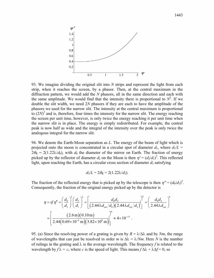
1443
93. We imagine dividing the original slit into N strips and represent the light from each strip, when it reaches the screen, by a phasor. Then, at the central maximum in the diffraction pattern, we would add the N phasors, all in the same direction and each with the same amplitude. We would find that the intensity there is proportional to N2. If we double the slit width, we need 2N phasors if they are each to have the amplitude of the phasors we used for the narrow slit. The intensity at the central maximum is proportional to (2N)2 and is, therefore, four times the intensity for the narrow slit. The energy reaching the screen per unit time, however, is only twice the energy reaching it per unit time when the narrow slit is in place. The energy is simply redistributed. For example, the central peak is now half as wide and the integral of the intensity over the peak is only twice the analogous integral for the narrow slit. 94. We denote the Earth-Moon separation as L. The energy of the beam of light which is projected onto the moon is concentrated in a circular spot of diameter d1, where d1/L = 2θR = 2(1.22λ/d0), with d0 the diameter of the mirror on Earth. The fraction of energy picked up by the reflector of diameter d2 on the Moon is then η' = (d2/d1)2. This reflected light, upon reaching the Earth, has a circular cross section of diameter d3 satisfying
d3/L = 2θR = 2(1.22λ/d2). The fraction of the reflected energy that is picked up by the telescope is then η'' = (d0/d3)2. Consequently, the fraction of the original energy picked up by the detector is
( )( )
( )( )( )( )
22 42
0 0 2 0 22
3 1 0 2
4
136 8
2.44 2.44 2.44
2.6m 0.10m4 10 .
2.44 0.69 10 m 3.82 10 m
em em em
d d d d ddd d d d d d d
η η η
−−
′ ′′= = = = λ λ λ
= ≈ ×
× ×
95. (a) Since the resolving power of a grating is given by R = λ/∆λ and by Nm, the range of wavelengths that can just be resolved in order m is ∆λ = λ/Nm. Here N is the number of rulings in the grating and λ is the average wavelength. The frequency f is related to the wavelength by f λ = c, where c is the speed of light. This means f ∆λ + λ∆f = 0, so

CHAPTER 36 1444
∆λ ∆ ∆= − = −λ λf
fc
f2
where f = c/λ is used. The negative sign means that an increase in frequency corresponds to a decrease in wavelength. We may interpret ∆f as the range of frequencies that can be resolved and take it to be positive. Then,
λ λ2
cf
Nm∆ =
and
∆f cNm
=λ
.
(b) The difference in travel time for waves traveling along the two extreme rays is ∆t = ∆L/c, where ∆L is the difference in path length. The waves originate at slits that are separated by (N – 1)d, where d is the slit separation and N is the number of slits, so the path difference is ∆L = (N – 1)d sin θ and the time difference is
∆tN d
c=
−1b gsin.
θ
If N is large, this may be approximated by ∆t = (Nd/c) sin θ. The lens does not affect the travel time. (c) Substituting the expressions we derived for ∆t and ∆f, we obtain
∆ ∆f t cNm
N dc
dm
= FHG IKJFHG IKJ= =λ λ
sin sin .θ θ 1
The condition d sin θ = mλ for a diffraction line is used to obtain the last result. 96. The central diffraction envelope spans the range –θ1 < θ < + θ1 where
11 sin ( / ).aθ λ−= The maxima in the double-slit pattern are located at
θ mmd
= −sin ,1
so that our range specification becomes
1 1 1sin sin sin ,ma d aλ λ λ− − − − < < +

1445
which we change (since sine is a monotonically increasing function in the fourth and first quadrants, where all these angles lie) to
− < < +a
md a
.
Rewriting this as –d/a < m < +d/a, we find –6 < m < +6, or, since m is an integer, –5 ≤ m ≤ +5. Thus, we find eleven values of m that satisfy this requirement. 97. The problem specifies d = 12/8900 using the mm unit, and we note there are no refraction angles greater than 90°. We convert λ = 500 nm to 5 × 10⁻⁴ mm and solve Eq. 36-25 for "mmax" (realizing it might not be an integer):
mmax = d sin 90°
λ = 12
(8900)(5 × 10⁻⁴) ≈ 2
where we have rounded down. There are no values of m (for light of wavelength λ) greater than m = 2. 98. Letting d sin θ = (L/N) sin θ = mλ, we get
λ =(L N
m/ ) sin ( .
( )( )θ
=× °
=10 10
1 10000500
7 nm)(sin 30 ) nm .
99. (a) Use of Eq. 36-25 for the limit-wavelengths (λ1 = 700 nm and λ2 = 550 nm) leads to the condition
m m1 2≥ for m1 + 1 = m2 (the low end of a high-order spectrum is what is overlapping with the high end of the next-lower-order spectrum). Assuming equality in the above equation, we can solve for “m1” (realizing it might not be an integer) and obtain m1 ≈ 4 where we have rounded up. It is the fourth order spectrum that is the lowest-order spectrum to overlap with the next higher spectrum. (b) The problem specifies d = (1/200) mm, and we note there are no refraction angles greater than 90°. We concentrate on the largest wavelength λ = 700 nm = 7 × 10⁻⁴ mm and solve Eq. 36-25 for “mmax” (realizing it might not be an integer):
max 4
sin 90 (1/ 200) mm 77 10 mm
dmλ −
°= = ≈
×
where we have rounded down. There are no values of m (for the appearance of the full spectrum) greater than m = 7.

CHAPTER 36 1446
100. Following Sample Problem 36-3, we use Eq. 36-17 and obtain L Dd= =
122164
. λm .
101. The dispersion of a grating is given by D = dθ/dλ, where θ is the angular position of a line associated with wavelength λ. The angular position and wavelength are related by d sin θ = mλ, where d is the slit separation (which we made boldfaced in order not to confuse it with the d used in the derivative, below) and m is an integer. We differentiate this expression with respect to θ to obtain
dd
mθ θλ
dcos ,=
or
D dd
m= =
θθλ dcos
.
Now m = (d/λ) sin θ, so
D = =d
dsin tan .θ
θθ
λ λcos
102. (a) Employing Eq. 36-3 with the small angle approximation (sin θ ≈ tan θ = y/D where y locates the minimum relative to the middle of the pattern), we find (with m = 1)
4
(0.90 mm)(0.40 mm) 800 mm 80 cm4.50 10 mm
yaDm −= = = =
λ ×
which places the screen 80 cm away from the slit. (b) The above equation gives for the value of y (for m = 3)
4(3) (3)(4.50 10 mm)(800 mm) 2.7 mm .(0.40 mm)
Dya
−λ ×= = =
Subtracting this from the first minimum position y = 0.9 mm, we find the result
1.8 mmy∆ = . 103. (a) We require that sin θ = mλ1,2/d ≤ sin 30°, where m = 1, 2 and λ1 = 500 nm. This gives
2 2(600nm) 2400nm 2.4 m.sin 30 sin 30
sd µλ≥ = = =
° °
For a grating of given total width L we have N L d d= ∝ −/ 1 , so we need to minimize d to maximize R mN d= ∝ −1 . Thus we choose d = 2400 nm = 2.4 µm.

1447
(b) Let the third-order maximum for λ2 = 600 nm be the first minimum for the single-slit diffraction profile. This requires that d sin θ = 3λ2 = a sin θ, or
a = d/3 = 2400 nm/3 = 800 nm = 0.80 µm. (c) Letting sin θ = mmaxλ2/d ≤ 1, we obtain
m dmax .≤ = =
λ2
2400800
3nmnm
Since the third order is missing the only maxima present are the ones with m = 0, 1 and 2. Thus, the largest order of maxima produced by the grating is m = 2. 104. For λ = 0.10 nm, we have scattering for order m, and for λ' = 0.075 nm, we have scattering for order m'. From Eq. 36-34, we see that we must require
m mλ = λ' ' which suggests (looking for the smallest integer solutions) that m = 3 and m' = 4. Returning with this result and with d = 0.25 nm to Eq. 36-34, we obtain
θ = = °−sin .1 37mdλ
2
Studying Figure 36-30, we conclude that the angle between incident and scattered beams is 180° – 2θ = 106°. 105. The key trigonometric identity used in this proof is sin(2θ) = 2sinθ cosθ. Now, we wish to show that Eq. 36-19 becomes (when d = a) the pattern for a single slit of width 2a (see Eq. 36-5 and Eq. 36-6):
I(θ) = Im
sin(2πasinθ/λ)
2πasinθ/λ
2
.
We note from Eq. 36-20 and Eq. 36-21, that the parameters β and α are identical in this case (when d = a), so that Eq. 36-19 becomes
I(θ) = Im
cos(πasinθ/λ)sin(πasinθ/λ)
πasinθ/λ
2
.
Multiplying numerator and denominator by 2 and using the trig identity mentioned above, we obtain
I(θ) = Im
2cos(πasinθ/λ)sin(πasinθ/λ)
2πasinθ/λ
2
= Im
sin(2πasinθ/λ)
2πasinθ/λ
2
which is what we set out to show.

CHAPTER 36 1448
106. Employing Eq. 36-3, we find (with m = 3 and all lengths in µm)
θ = =− −sin sin ( )( . )1 1 3 052
ma
which yields θ = 48.6°. Now, we use the experimental geometry (tanθ = y/D where y locates the minimum relative to the middle of the pattern) to find
y D= =tan .θ 2 27 m. 107. (a) The central diffraction envelope spans the range – θ1 < θ < +θ1 where
11 sin ,
aλθ −=
which could be further simplified if the small-angle approximation were justified (which it is not, since a is so small). The maxima in the double-slit pattern are at
θ mmd
= −sin ,1
so that our range specification becomes
1 1 1sin sin sin ,ma d aλ λ λ− − − − < < +
which we change (since sine is a monotonically increasing function in the fourth and first quadrants, where all these angles lie) to
− < < +a
md a
.
Rewriting this as -d/a < m < +d/a we arrive at the result mmax < d/a < mmax + 1. Due to the symmetry of the pattern, the multiplicity of the m values is 2mmax + 1 = 17 so that mmax = 8, and the result becomes
8 < da < 9
where these numbers are as accurate as the experiment allows (that is, "9" means "9.000" if our measurements are that good). 108. We refer (somewhat sloppily) to the 400 nm wavelength as “blue” and the 700 nm wavelength as “red.” Consider Eq. 36-25 (mλ = d sinθ), for the 3rd order blue, and also for the 2nd order red:

1449
(3) λblue = 1200 nm = d sin(θblue)
(2) λred = 1400 nm = d sin(θred) . Since sine is an increasing function of angle (in the first quadrant) then the above set of values make clear that θred (second order) > θblue (third order) which shows that the spectrums overlap (regardless of the value of d). 109. One strategy is to divide Eq. 36-25 by Eq. 36-3, assuming the same angle (a point we’ll come back to, later) and the same light wavelength for both:
sin' ' sin
m m d dm m a a
λ θλ θ
= = = .
We recall that d is measured from middle of transparent strip to the middle of the next transparent strip, which in this particular setup means d = 2a. Thus, m/m′ = 2, or m = 2m′ . Now we interpret our result. First, the division of the equations is not valid when m = 0 (which corresponds to θ = 0), so our remarks do not apply to the m = 0 maximum. Second, Eq. 36-25 gives the “bright” interference results, and Eq. 36-3 gives the “dark” diffraction results (where the latter overrules the former in places where they coincide – see Figure 36-17 in the textbook). For m′ = any nonzero integer, the relation m = 2m′ implies that m = any nonzero even integer. As mentioned above, these are occurring at the same angle, so the even integer interference maxima are eliminated by the diffraction minima. 110. The derivation is similar to that used to obtain Eq. 36-27. At the first minimum beyond the mth principal maximum, two waves from adjacent slits have a phase difference of ∆φ = 2πm + (2π/N), where N is the number of slits. This implies a difference in path length of
∆L = (∆φ/2π)λ = mλ + (λ/N). If θm is the angular position of the mth maximum, then the difference in path length is also given by ∆L = d sin(θm + ∆θ). Thus
d sin (θm + ∆θ) = mλ + (λ/N). We use the trigonometric identity
sin(θm + ∆θ) = sin θm cos ∆θ + cos θm sin ∆θ. Since ∆θ is small, we may approximate sin ∆θ by ∆θ in radians and cos ∆θ by unity. Thus,
CHAPTER 36 1450
d sin θm + d ∆θ cos θm = mλ + (λ/N). We use the condition d sin θm = mλ to obtain d ∆θ cos θm = λ/N and
∆θθ
=λ
N d mcos.
111. There are two unknowns, the x-ray wavelength λ and the plane separation d, so data for scattering at two angles from the same planes should suffice. The observations obey Bragg’s law, so
2 1 1d msinθ = , 2 2 2d msinθ = However, these cannot be solved for the unknowns. For example, we can use the first equation to eliminate λ from the second. We obtain
m m2 1 1 2sin sin ,θ θ= an equation that does not contain either of the unknowns. 112. The problem specifies d = (1 mm)/500 = 2.00 µm unit, and we note there are no refraction angles greater than 90°. We concentrate on the largest wavelength λ = 700 nm = 0.700 µm and solve Eq. 36-25 for "mmax" (realizing it might not be an integer):
maxsin 90 2.00 m 2
0.700 md dm µ
λ λ µ°
= = = ≈
where we have rounded down. There are no values of m (for appearance of the full spectrum) greater than m = 2. 113. When the speaker phase difference is π rad (180°), we expect to see the “reverse” of Fig. 36-15 [translated into the acoustic context, so that “bright” becomes “loud” and “dark” becomes “quiet”]. That is, with 180° phase difference, all the peaks in Fig. 36-15 become valleys and all the valleys become peaks. As the phase changes from zero to 180° (and similarly for the change from 180° back to 360° = original pattern), the peaks should shift (and change height) in a continuous fashion – with the most dramatic feature being a large “dip” in the center diffraction envelope which deepens until it seems to split the central maximum into smaller diffraction maxima which (once the phase difference reaches π rad) will be located at angles given by a sinθ = ± λ. How many interference fringes would actually “be inside” each of these smaller diffraction maxima would, of course, depend on the particular values of a, λ and d.