Chapter # 1 Digital Logic Circuits - PSAU · PDF fileChapter # 1 Digital Logic Circuits ... an...
11
CS 328: COMPUTER ARCHITECTURE Chapter # 1 Digital Logic Circuits What is “Computer Architecture?” Computer Architecture = Instruction Set Architecture + Machine Organization Forces on Computer Architecture Technology => dramatic change Processor logic capacity: about 30% per year clock rate: about 20% per year So… advanced functions (e.g., multimedia functions in some Pentiums) and high-speed features (multiple pipelines, larger caches) Memory DRAM capacity: about 60% per year (4x every 3 years) Memory speed: about 10% per year Cost per bit: improves about 25% per year So… larger memory => more challenging applications (e.g., atmospheric modeling, astrophysics modeling) Disk capacity: about 60% per year So … huge disk capacities => large data storage (video, music files, large data for various applications)
Transcript of Chapter # 1 Digital Logic Circuits - PSAU · PDF fileChapter # 1 Digital Logic Circuits ... an...
CS 328: COMPUTER ARCHITECTURE
Chapter # 1
Digital Logic Circuits
What is “Computer Architecture?”
Computer Architecture = Instruction Set Architecture + Machine Organization
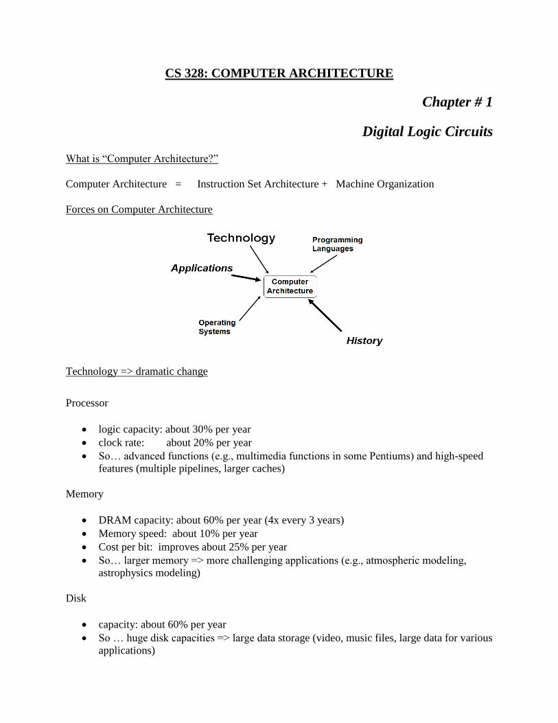
Forces on Computer Architecture
Technology => dramatic change
Processor
logic capacity: about 30% per year
clock rate: about 20% per year
So… advanced functions (e.g., multimedia functions in some Pentiums) and high-speed
features (multiple pipelines, larger caches)
Memory
DRAM capacity: about 60% per year (4x every 3 years)
Memory speed: about 10% per year
Cost per bit: improves about 25% per year
So… larger memory => more challenging applications (e.g., atmospheric modeling,
astrophysics modeling)
Disk
capacity: about 60% per year
So … huge disk capacities => large data storage (video, music files, large data for various
applications)
Computer Organization versus Computer Architecture
It is difficult to make a sharp distinction between these two. However, architecture refers tthe
attributes of a computer that are visible ta programmer, including
The instruction set
The number of bits used to represent various data types
I/mechanisms
Memory addressing modes, etc.
On the other hand, organization refers to the operational units of a computer and their
interconnections that realize the architectural specifications. These include
The control signals
Interfaces between the computer and its peripherals
Memory technology used, etc.
It is an architectural issue whether a computer will have a specific instruction or not, while it is
an organizational issue how that instruction will be implemented.
1.1 Introduction Of Digital Computers:
Digital computer, any of a class of devices capable of solving problems by processing
information in discrete form. It operates on data, including magnitudes, letters, and symbols, that
are expressed in binary form—i.e., using only the two digits 0 and 1. By counting, comparing,
and manipulating these digits or their combinations according to a set of instructions held in its
memory, a digital computer can perform such tasks as to control industrial processes and
regulate the operations of machines; analyze and organize vast amounts of business data; and
simulate the behavior of dynamic systems (e.g., global weather patterns and chemical reactions)
in scientific research.
A digital computer typically consists of a control unit, an arithmetic-logic unit, a memory unit,
and input/output units, as illustrated in the figure. The arithmetic-logic unit (ALU) performs
simple addition, subtraction, multiplication, division, and logic operations—such as OR and
AND. The main computer memory, usually high-speed random-access memory (RAM), stores
instructions and data. The control unit fetches data and instructions from memory and effects the
operations of the ALU. The control unit and ALU usually are referred to as a processor, or
central processing unit (CPU). The operational speed of the CPU primarily determines the speed
of the computer as a whole. The basic operation of the CPU is analogous to a computation
carried out by a person using an arithmetic calculator, as illustrated in the figure. The control unit
corresponds to the human brain and the memory to a notebook that stores the program, initial
data, and intermediate and final computational results. In the case of an electronic computer, the
CPU and fast memories are realized with transistor circuits.
I/O units, or devices, are commonly referred to as computer peripherals and consist of input units
(such as keyboards.

Digital computer Organization
1.2 Fundamental Building Blocks:
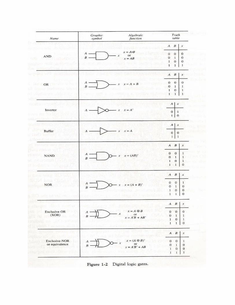
Logic gates:
A logic gate is an idealized or physical device implementing a Boolean function, that is, it
performs a logical operation on one or more logical inputs, and produces a single logical output.
Depending on the context, the term may refer to an ideal logic gate, one that has for instance zero
rise time and unlimited fan-out, or it may refer to a non-ideal physical device.
Logic gates are primarily implemented using diodes or transistors acting as electronic switches,
but can also be constructed using electromagnetic relays (relay logic), fluidic logic, pneumatic
logic, optics, molecules, or even mechanical elements. With amplification, logic gates can be
cascaded in the same way that Boolean functions can be composed, allowing the construction of
a physical model of all of Boolean logic, and therefore, all of the algorithms and mathematics
that can be described with Boolean logic.
Combinational circuits:
In digital circuit theory, combinational logic (sometimes also referred to as time-independent
logic ) is a type of digital logic which is implemented by Boolean circuits, where the output is a
pure function of the present input only. This is in contrast to sequential logic, in which the output
depends not only on the present input but also on the history of the input. In other words,
sequential logic has memory while combinational logic does not.
Combinational logic is used in computer circuits to perform Boolean algebra on input signals and
on stored data. Practical computer circuits normally contain a mixture of combinational and
sequential logic. For example, the part of an arithmetic logic unit, or ALU, that does
mathematical calculations is constructed using combinational logic. Other circuits used in
computers, such as half adders, full adders, half subtractors, full subtractors, multiplexers, DE
multiplexers, encoders and decoders are also made by using combinational logic.
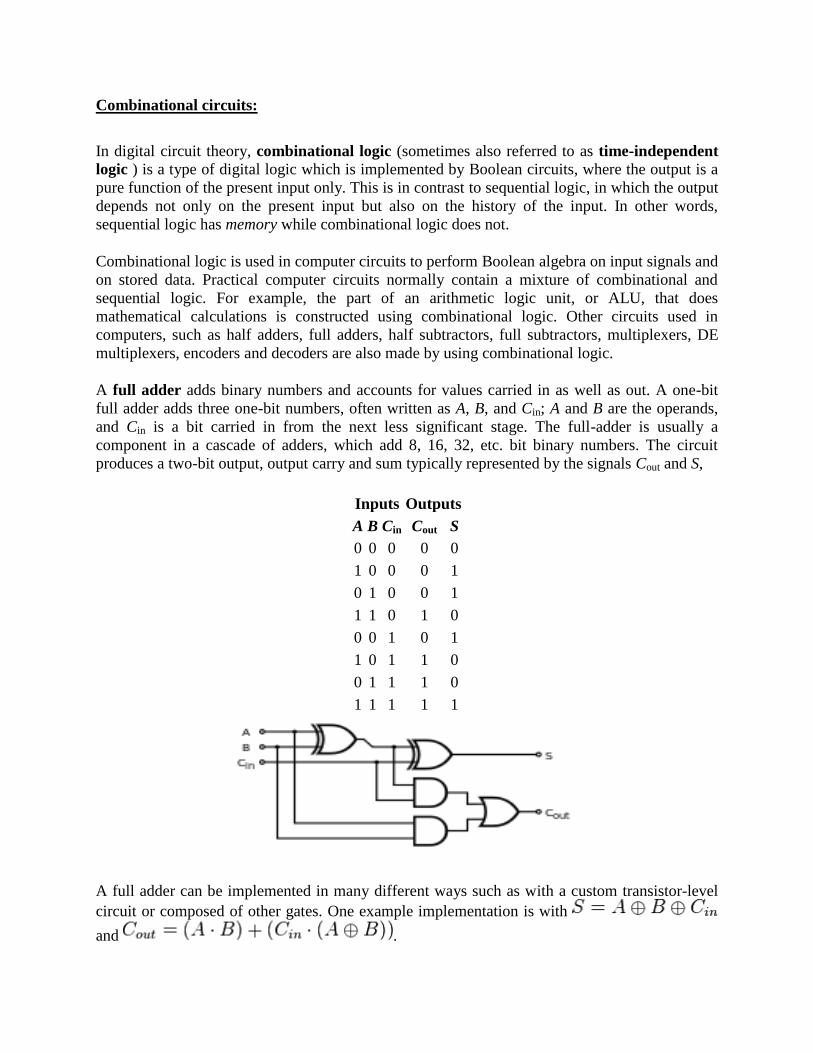
A full adder adds binary numbers and accounts for values carried in as well as out. A one-bit
full adder adds three one-bit numbers, often written as A, B, and Cin; A and B are the operands,
and Cin is a bit carried in from the next less significant stage. The full-adder is usually a
component in a cascade of adders, which add 8, 16, 32, etc. bit binary numbers. The circuit
produces a two-bit output, output carry and sum typically represented by the signals Cout and S,
Inputs Outputs
A B Cin Cout S
0 0 0 0 0
1 0 0 0 1
0 1 0 0 1
1 1 0 1 0
0 0 1 0 1
1 0 1 1 0
0 1 1 1 0
1 1 1 1 1
A full adder can be implemented in many different ways such as with a custom transistor-level
circuit or composed of other gates. One example implementation is with
and .

In this implementation, the final OR gate before the carry-out output may be replaced by an
XOR gate without altering the resulting logic. Using only two types of gates is convenient if the
circuit is being implemented using simple IC chips which contain only one gate type per chip. In
this light, Cout can be implemented as .
A full adder can be constructed from two half adders by connecting A and B to the input of one
half adder, connecting the sum from that to an input to the second adder, connecting Ci to the
other input and OR the two carry outputs. Equivalently, S could be made the three-bit XOR of A,
B, and Ci, and Cout could be made the three-bit majority function of A, B, and Cin.
Sequential circuit:
Block diagram of Sequential Circuit
Flip flops:
1.3 Logical Expressions (Boolean Algebra)
In mathematics and mathematical logic, Boolean algebra is the subarea of algebra in which the
values of the variables are the truth values true and false, usually denoted 1 and 0 respectively.
Instead of elementary algebra where the values of the variables are numbers, and the main
operations are addition and multiplication, the main operations of Boolean algebra are the
conjunction and, denoted ∧, the disjunction or, denoted ∨, and the negation not, denoted ¬.
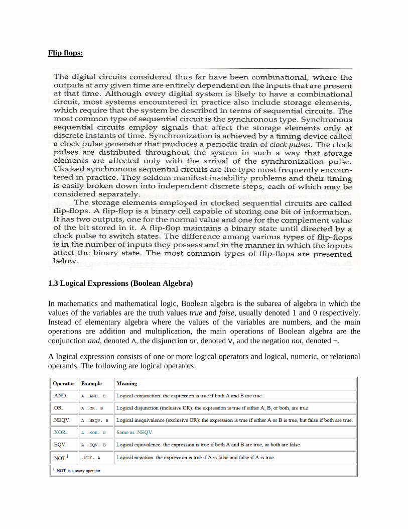
A logical expression consists of one or more logical operators and logical, numeric, or relational
operands. The following are logical operators:
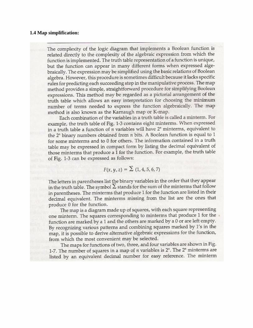
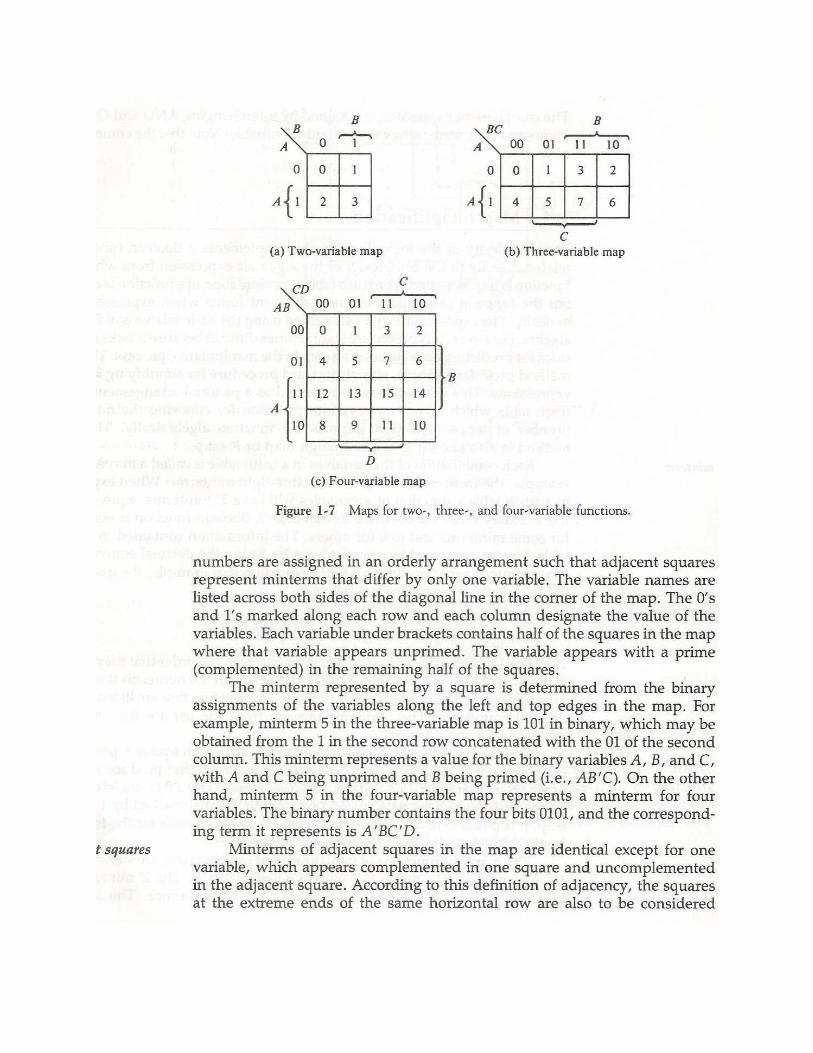
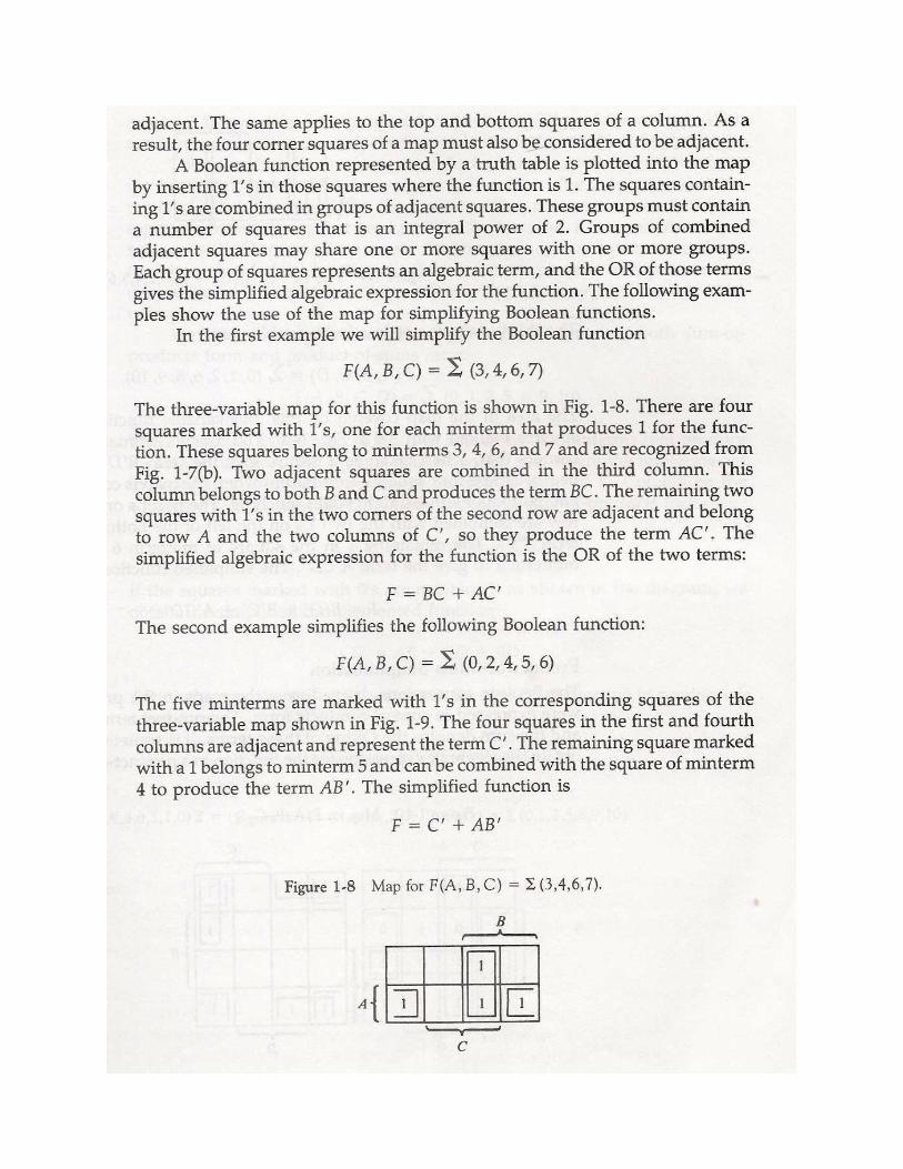
1.4 Map simplification: