BUILDING AND SAFETY DEPARTMENT - City of Palmdale
7
As a covered entity under Title II of the Americans with Disabilities Act, the City of Palmdale does not discriminate on the basis of disability and upon request will provide reasonable accommodation to ensure equal access to its programs, services and activities. For efficient handling of information internally and in the internet, conversion to this new format of code related and administrative information bulletins including MGD and RGA that were previously issued will allow flexibility and timely distribution of information to the public. 38250 SIERRA HIGHWAY, PALMDALE, CA 93550 Tel. No. (661) 267-5353 - Fax. No. (661) 267-5355 Date: 02/06/2020 BUILDING AND SAFETY DEPARTMENT Y / N Worksheet for 1 and 2 Family Dwelling Expedited PV System Plan Check General Requirements System size is 10 kW alternating current nameplate rating or less The solar array is roof-mounted on one- or two-family dwelling or accessory structure The solar panel/module arrays will not exceed the maximum legal building height Solar system is utility interactive and without battery storage Permit application is completed and attached The solar panel / module arrays are set clear of plumbing and mechanical vents Supplied Diagrams Is a basic site diagram supplied with the permit package. Location of major equipment identified on plan. Is a one-line electrical diagram supplied with the permit package? Array configuration shown Combiner/junction box identified Equipment grounding specified Disconnect specified System grounding specified Point of connection attachment method identified Inverter Information Are cut sheets provided for Inverter? Is inverter listed for utility interactivity (see CEC list of Eligible Inverters) For central/string inverter systems, strings are not combined prior to the inverter For central/string inverter systems: No more than two inverters are utilized PV Module Information Are cut sheets provided for PV modules? Are the modules listed? (see CEC list of Eligible PV Modules) Maximum permissible system voltage from listing label Voltage at Pmax from listing label Current at Pmax from listing label
Transcript of BUILDING AND SAFETY DEPARTMENT - City of Palmdale
As a covered entity under Title II of the Americans with Disabilities Act, the City of Palmdale does not discriminate on the basis of disability and upon request will provide reasonable accommodation to ensure
equal access to its programs, services and activities. For efficient handling of information internally and in the internet, conversion to this new format of code related and administrative information bulletins
including MGD and RGA that were previously issued will allow flexibility and timely distribution of information to the public.
38250 SIERRA HIGHWAY, PALMDALE, CA 93550 Tel. No. (661) 267-5353 - Fax. No. (661) 267-5355 Date: 02/06/2020
BUILDING AND SAFETY DEPARTMENT
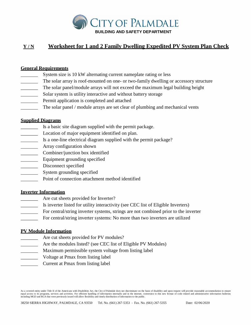
Y / N Worksheet for 1 and 2 Family Dwelling Expedited PV System Plan Check
General Requirements
System size is 10 kW alternating current nameplate rating or less
The solar array is roof-mounted on one- or two-family dwelling or accessory structure
The solar panel/module arrays will not exceed the maximum legal building height
Solar system is utility interactive and without battery storage
Permit application is completed and attached
The solar panel / module arrays are set clear of plumbing and mechanical vents
Supplied Diagrams
Is a basic site diagram supplied with the permit package.
Location of major equipment identified on plan.
Is a one-line electrical diagram supplied with the permit package?
Array configuration shown
Combiner/junction box identified
Equipment grounding specified
Disconnect specified
System grounding specified
Point of connection attachment method identified
Inverter Information
Are cut sheets provided for Inverter?
Is inverter listed for utility interactivity (see CEC list of Eligible Inverters)
For central/string inverter systems, strings are not combined prior to the inverter
For central/string inverter systems: No more than two inverters are utilized
PV Module Information
Are cut sheets provided for PV modules?
Are the modules listed? (see CEC list of Eligible PV Modules)
Maximum permissible system voltage from listing label
Voltage at Pmax from listing label
Current at Pmax from listing label

As a covered entity under Title II of the Americans with Disabilities Act, the City of Palmdale does not discriminate on the basis of disability and upon request will provide reasonable accommodation to ensure
equal access to its programs, services and activities. For efficient handling of information internally and in the internet, conversion to this new format of code related and administrative information bulletins
including MGD and RGA that were previously issued will allow flexibility and timely distribution of information to the public.
38250 SIERRA HIGHWAY, PALMDALE, CA 93550 Tel. No. (661) 267-5353 - Fax. No. (661) 267-5355 Date: 02/06/2020
Electrical requirements
For central/string inverter systems, strings are not combined prior to the inverter
PV module short circuit current (ISC) is less than 13 Amps
System does not utilize storage batteries, charge controllers, or trackers
PV system is not a hybrid or bipolar system
For central/string inverter systems: No more than two inverters are utilized
The PV system is interconnected to a single-phase AC service panel of nominal
120/220 Vac with a bus bar rating of 225 A or less
No more than 4 photovoltaic module strings are connected to each Maximum PowerPoint
Tracking (MPPT) input where source circuit fusing is included in the inverter
Fuses (if needed) are rated to the series fuse rating of the PV module
No more than 1 non-inverter integrated DC combiner is utilized per inverter.
A Solar PV Standard Plan and supporting documentation is completed and attached.
Fire Safety Requirements
______ Clear access pathways provided
______ Fire classification solar system is provided
______ All required markings and labels are provided per NEC requirements
______ A diagram of the roof layout of all panels, modules, clear access pathways and approximate
locations of electrical disconnecting means and roof access points is completed and attached
STRUCTURAL CRITERIA FOR RESIDENTIAL FLUSH MOUNT SOLAR ARRAYS
(The following sections are not required if Structural Evaluation and Calculations are provided by a Registered Design Professional)
Roof Information
Age of building (roof structure)
Identify roofing type (e.g. comp shingle, masonry tile, shake, etc…)
Visual Review/Contractor’s Site Audit of Existing Conditions:
______ 1) Is the roof a single roof without a reroof overlay?
______ 2) Does the roof structure appear structurally sound, without signs of alterations
or significant structural deterioration or sagging, as illustrated in Figure 1?
Roof Structure Data:
Measured roof slope (e.g. 6:12): ___:___
Measured rafter spacing (center-to-center): ___ in
Type of roof framing (rafter or manufactured truss): _____
Measured rafter size (e.g. 1-3/4” x 3-3/4”), : ____” x ____”
Measured rafter horizontal span (see figure 4): ___’-___”
Horizontal rafter span per table 2: ____’ - ____”
Is measured horizontal rafter span less than in Table 2 span or Truss? ____

As a covered entity under Title II of the Americans with Disabilities Act, the City of Palmdale does not discriminate on the basis of disability and upon request will provide reasonable accommodation to ensure
equal access to its programs, services and activities. For efficient handling of information internally and in the internet, conversion to this new format of code related and administrative information bulletins
including MGD and RGA that were previously issued will allow flexibility and timely distribution of information to the public.
38250 SIERRA HIGHWAY, PALMDALE, CA 93550 Tel. No. (661) 267-5353 - Fax. No. (661) 267-5355 Date: 02/06/2020
Array Information
Number of modules in series
Number of parallel source circuits
Total number of modules
Is the plane of the modules (panels) parallel to the plane of the roof?
Is there a 2” to 10” gap between underside of module and the roof surface?
Modules do not overhang any roof edges (ridges, hips, gable ends, eaves)?
Do the modules plus support components weigh no more than: 4 psf for photovoltaic
arrays or 5 psf for solar thermal arrays?
Does the array cover no more than half of the total roof area (all roof planes)?
Are solar support component manufacturer’s project-specific completed worksheets,
tables with relevant cells circled, or web-based calculator results attached?
Is a roof plan of the module and anchor layout attached? (see Figure 2)
Downward Load Check (Anchor Layout Check):
1) Proposed anchor horizontal spacing (see Figure 2): ‘- “ft.-in
2) Horizontal anchor spacing per Table 1: ‘- “ft.-in
3) Is proposed anchor horizontal spacing equal to or less than Table 1 spacing?
Wind Uplift Check (Anchor Fastener Check):
1) Anchor fastener data (see Figure 3):
a. Diameter of lag screw, hanger bolt or self-drilling screw: inch
b. Embedment depth of rafter: inch
c. Number of screws per anchor (typically one):
OR does the anchor fastener meet the manufacturer’s guidelines?
Notes:
1. These criteria are intended for expedited solar permitting process.
2. If any items are checked NO, revise design to fit within Eligibility Checklist, otherwise permit
application may go through standard process with extended review times.
Electrical plans shall be completed, stamped and signed by a California Licensed Electrical Engineer or
a C-10 electrical contractor.
Project Address:
Applicant Signature:
Applicants Printed Name:
Contractor’s License Number and type:

Table 1. Maximum Horizontal Spacing
Roof Slope
Rafter Spacing
16” o.c. 24” o.c. 32” o.c.
Photovoltaic Arrays (4 psf max) Flat to 6:12 0° to 26° 5’-4” 6’-0” 5’-4”
7:12 to 12:12 27° to 45° 1’-4” 2’-0” 2’-8”
13:12 to 24:12 46° to 63° 1’-4” 2’-0” 2’-8”
Solar Thermal Arrays (5 psf max) Flat to 6:12 0° to 26° 4’-0” 4’-0” 5’-4”
7:12 to 12:12 27° to 45° 1’-4” 2’-0” 2’-8”
13:12 to 24:12 46° to 63° Calc. Req’d. Calc. Req’d. Calc. Req’d.
Solar support component manufacturer’s guidelines may be relied upon to ensure the array above the roof is properly designed, but manufacturer’s guidelines typically do NOT check to ensure that the roof itself can support the concentrated loads from the solar array. Table 1 assumes that the roof complied with the building code in effect at the time of construction, and places limits on anchor horizontal spacing to ensure that a roof structure is not overloaded under either downward loads or wind uplift loads. Note 4 below lists the basic assumptions upon which this table is based.
Table 1 Notes:
1. Anchors are also known as “stand-offs,” “feet,” “mounts” or “points of attachment.” Horizontal anchor spacing is also known as “cross-slope” or “east-west” anchor spacing (see Figure 2).
2. If anchors are staggered from row-to-row going up the roof, the anchor spacing may be twice that shown above, but no greater than 6’-0”.
3. For manufactured plated wood trusses at slopes of flat to 6:12, the horizontal anchor spacing shall not exceed 4’-0” and anchors in adjacent rows shall be staggered.
4. This table is based on the following assumptions:
• The roof structure conformed to building code requirements at the time it was built.
• The attached list of criteria is met.
• Mean roof height is not greater than 40 feet.
• Roof sheathing is at least 7/16” thick oriented strand board or plywood. 1x skip sheathing is acceptable.
• If the dwelling is in Wind Exposure B (typical urban, suburban or wooded areas farther than 500 yards from large open fields), no more than one of the following conditions apply:
– The dwelling is located in a Special Wind Region with design wind speed between 115 and 130 mph per ASCE 7-10.
– The dwelling is located on the top half of a tall hill, provided average slope is less than 15%.
• If the dwelling is in Wind Exposure C (within 500 yards of large open fields or grasslands), all of the following conditions apply.
– Design wind speed is 110 mph or less (not in a Special Wind Region).
– The dwelling is not located on the top half of a tall hill.
• The solar array displaces roof live loads (temporary construction loads) that the roof was originally designed to carry.
• The Structural Technical Appendix provides additional information about analysis assumptions.

Table 2. Roof Rafter Maximum Horizontal Span (feet – inches)1
Assumed Vintage
Nominal
Size
Actual Size
Non-Tile Roof2 Tile Roof3
Rafter Spacing
16” o.c. 24” o.c. 32” o.c. 16” o.c. 24” o.c. 32” o.c.
Post-1960
2x4 1 ½”x 3 ½” 9’-0” 8’-0” 6’-6” 8’-6” 6’-11” 5’-6” 2x6 1 ½”x 5 ½” 14’-4” 11’-9” 9’-6” 12’-5” 10’-2” 8’-0”
2x8 1 ½” x 7 ¼” 18’-2” 14’-10” 12’-0” 15’-9” 12’-10” 10’-3”
Pre-1960
2x4 1 ½” x 3 ¾” 11’-3” 9’-9” 7’-9” 10’-3” 8’-6” 6’-9”
2x6 1 ½”x 5 ¾” 17’-0” 14’-0” 11’-3” 14’-9” 12’-0” 9’-9”
2x8 1 ½” x 7 ¾” 22’-3” 18’-0” 14’-6” 19’-0” 15’-6” 12’-6”
Beyond a visual review by the contractor checking for unusual sagging or deterioration, some CBOs may want additional assurance that the roof structure complies with structural building code requirements. Table 2 is an optional table some CBOs may elect to use to provide additional assurance by requiring a check of existing roof rafter spans, and supports optional criteria 1.B.5 and 1.B.6. For post-1960 construction, these span tables match the rafter span tables found in the 2016 California Building and Residential codes. For pre-1960 construction, the rafter span tables are based on structural calculations with lumber sizes and wood species and grade appropriate for older construction. Note 5 below lists the basic assumptions upon which this table is based.
Table 2 Notes:
1. See Figure 4 for definition of roof rafter maximum horizontal span. 2. “Non-tile Roof” = asphalt shingle, wood shingle and wood shake, with an assumed roof assembly
weight of 10 psf. 3. “Tile Roof” = clay tile or cement tile, with an assumed roof assembly weight of 20 psf
4. Unaltered manufactured plated-wood trusses may be assumed to be code compliant and meet intent of Table 2.
5. This table is based on the following assumptions:
• Span/deflection ratio is equal to or greater than 180.
• For post-1960 construction, wood species and grade is Douglas Fir-Larch No. 2.
• For pre-1960 construction, wood species and grade is Douglas Fir-Larch No. 1.
• Other wood species and/or grade are also acceptable if allowable bending stress is equal or greater to that listed.

Figure 1 Roof Visual Structural Review (Contractor's Site Audit) of Existing Conditions.
The site auditor should verify the following. 1. No visually apparent disallowed rafter holes, notches and truss modifications as shown above.
2. No visually apparent structural decay or unrepaired fire damage.
3. Roof sag, measured in inches, is not more than the rafter or ridge beam length in feet divided by 20.
Rafters that fail the above criteria should not be used to support solar arrays unless they are first strengthened.
Figure 2 Sample Solar Panel Array and Anchor Layout Diagram (Roof Plan)

Figure 4 Typical Anchor with Lag Screw Attachment
Figure 3 Definition of Rafter Horizontal Span