A810 Manual Carmanah
28
OWNER’S MANUAL A810 Solar Obstruction Lighting System
-
Upload
jose-gallardo -
Category
Documents
-
view
227 -
download
0
Transcript of A810 Manual Carmanah

8/3/2019 A810 Manual Carmanah
http://slidepdf.com/reader/full/a810-manual-carmanah 1/28
OWNER’S MANUAL
A810 Solar Obstruction Lighting System

8/3/2019 A810 Manual Carmanah
http://slidepdf.com/reader/full/a810-manual-carmanah 2/28
8/3/2019 A810 Manual Carmanah
http://slidepdf.com/reader/full/a810-manual-carmanah 3/28
Owner’s Manual | A810 Solar Obstruction Lighting System
3
© 2008 Carmanah Technologies CorporationLast revised: October 2008
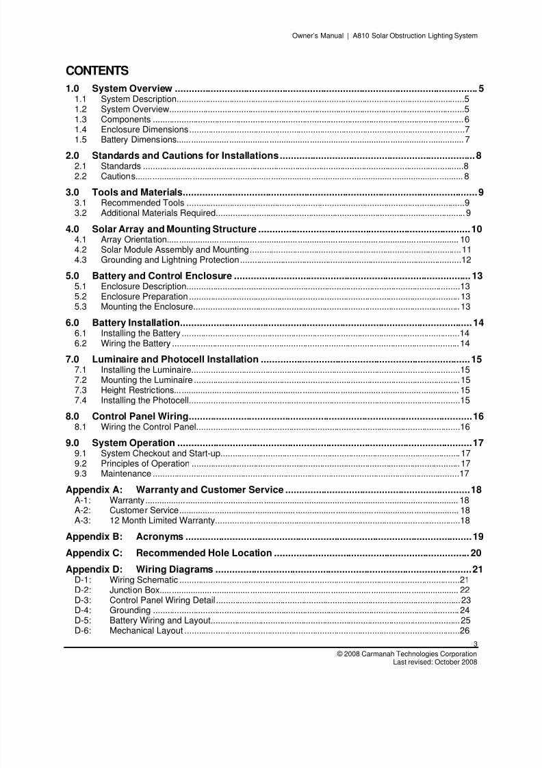
CONTENTS
1.0 System Overview .............................................................................................................. 5 1.1 System Description.........................................................................................................................5 1.2 System Overview............................................................................................................................5 1.3 Components ...................................................................................................................................6 1.4 Enclosure Dimensions....................................................................................................................7 1.5 Battery Dimensions......................................................................................................................... 7
2.0 Standards and Cautions for Installations.......................................................................8 2.1 Standards .......................................................................................................................................8 2.2 Cautions.......................................................................................................................................... 8
3.0 Tools and Materials...........................................................................................................9 3.1 Recommended Tools .....................................................................................................................9 3.2 Additional Materials Required.........................................................................................................9
4.0 Solar Array and Mounting Structure .............................................................................10 4.1 Array Orientation........................................................................................................................... 10 4.2 Solar Module Assembly and Mounting.........................................................................................11 4.3 Grounding and Lightning Protection.............................................................................................12
5.0 Battery and Control Enclosure ...................................................................................... 13 5.1 Enclosure Description...................................................................................................................13 5.2 Enclosure Preparation ..................................................................................................................13 5.3 Mounting the Enclosure................................................................................................................13
6.0 Battery Installation..........................................................................................................14 6.1 Installing the Battery .....................................................................................................................14 6.2 Wiring the Battery .........................................................................................................................14
7.0 Luminaire and Photocell Installation ............................................................................15 7.1 Installing the Luminaire.................................................................................................................15 7.2 Mounting the Luminaire ................................................................................................................15 7.3 Height Restrictions........................................................................................................................ 15 7.4
Installing the Photocell..................................................................................................................15
8.0 Control Panel Wiring.......................................................................................................16
8.1 Wiring the Control Panel...............................................................................................................16 9.0 System Operation ...........................................................................................................17
9.1 System Checkout and Start-up.....................................................................................................17 9.2 Principles of Operation .................................................................................................................17 9.3 Maintenance .................................................................................................................................17
Appendix A: Warranty and Customer Service ...................................................................18 A-1: Warranty.................................................................................................................................... 18 A-2: Customer Service...................................................................................................................... 18 A-3: 12 Month Limited Warranty.......................................................................................................18
Appendix B: Acronyms ........................................................................................................19 Appendix C: Recommended Hole Location ....................................................................... 20 Appendix D: Wiring Diagrams .............................................................................................21
D-1: Wiring Schematic ......................................................................................................................21 D-2: Junction Box.............................................................................................................................. 22 D-3: Control Panel Wiring Detail.......................................................................................................23 D-4: Grounding ................................................................................................................................. 24 D-5: Battery Wiring and Layout.........................................................................................................25 D-6: Mechanical Layout ....................................................................................................................26
8/3/2019 A810 Manual Carmanah
http://slidepdf.com/reader/full/a810-manual-carmanah 4/28
Owner’s Manual | A810 Solar Obstruction Lighting System
4
Carmanah Technologies Corp. Copyright © 2008Last revised: October 2008
8/3/2019 A810 Manual Carmanah
http://slidepdf.com/reader/full/a810-manual-carmanah 5/28
Owner’s Manual | A810 Solar Obstruction Lighting System
5
© 2008 Carmanah Technologies CorporationLast revised: October 2008
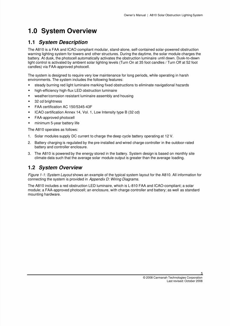
1.0 System Overview
1.1 System Description
The A810 is a FAA and ICAO compliant modular, stand-alone, self-contained solar-powered obstructionwarning lighting system for towers and other structures. During the daytime, the solar module charges the
battery. At dusk, the photocell automatically activates the obstruction luminaire until dawn. Dusk-to-dawnlight control is activated by ambient solar lighting levels (Turn On at 35 foot candles / Turn Off at 52 footcandles) via FAA-approved photocell.
The system is designed to require very low maintenance for long periods, while operating in harshenvironments. The system includes the following features: steady burning red light luminaire marking fixed obstructions to eliminate navigational hazards
high-efficiency high-flux LED obstruction luminaire
weather/corrosion resistant luminaire assembly and housing
32 cd brightness
FAA certification AC 150/5345-43F
ICAO certification Annex 14, Vol. 1, Low Intensity type B (32 cd) FAA-approved photocell
minimum 5-year battery life
The A810 operates as follows:
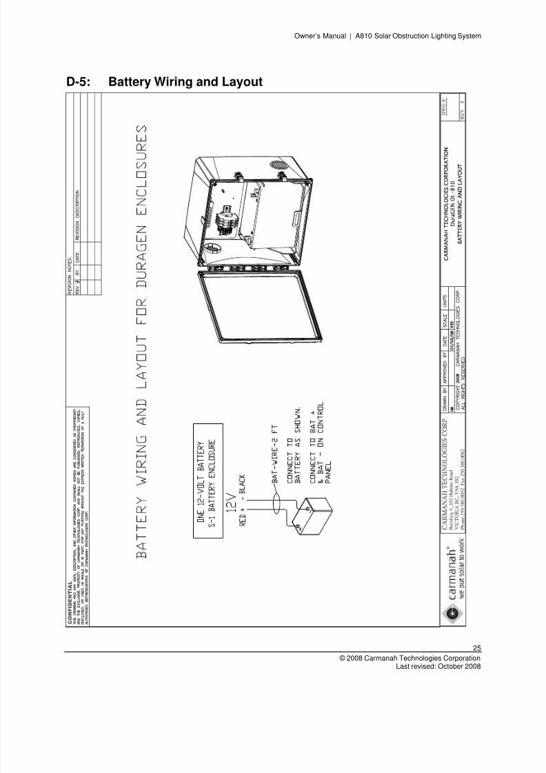
1. Solar modules supply DC current to charge the deep cycle battery operating at 12 V.
2. Battery charging is regulated by the pre-installed and wired charge controller in the outdoor-ratedbattery and controller enclosure.
3. The A810 is powered by the energy stored in the battery. System design is based on monthly siteclimate data such that the average solar module output is greater than the average loading.
1.2 System Overview
Figure 1-1: System Layout shows an example of the typical system layout for the A810. All information forconnecting the system is provided in Appendix D: Wiring Diagrams.
The A810 includes a red obstruction LED luminaire, which is L-810 FAA and ICAO-compliant; a solarmodule; a FAA-approved photocell; an enclosure, with charge controller and battery; as well as standardmounting hardware.
8/3/2019 A810 Manual Carmanah
http://slidepdf.com/reader/full/a810-manual-carmanah 6/28
Owner’s Manual | A810 Solar Obstruction Lighting System
6
Carmanah Technologies Corp. Copyright © 2008Last revised: October 2008
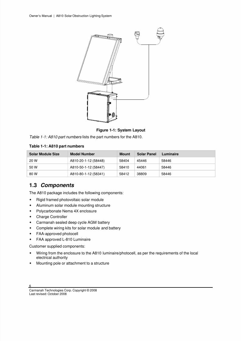
Figure 1-1: System Layout
Table 1-1: A810 part numbers lists the part numbers for the A810.
Table 1-1: A810 part numbers
Solar Module Size Model Number Mount Solar Panel Luminaire
20 W A810-20-1-12 (58448) 58404 45446 58446
50 W A810-50-1-12 (58447) 58410 44061 58446
80 W A810-80-1-12 (58341) 58412 38809 58446
1.3 Components
The A810 package includes the following components:
Rigid framed photovoltaic solar module
Aluminum solar module mounting structure
Polycarbonate Nema 4X enclosure
Charge Controller
Carmanah sealed deep cycle AGM battery
Complete wiring kits for solar module and battery
FAA-approved photocell
FAA approved L-810 Luminaire
Customer supplied components:
Wiring from the enclosure to the A810 luminaire/photocell, as per the requirements of the localelectrical authority
Mounting pole or attachment to a structure
8/3/2019 A810 Manual Carmanah
http://slidepdf.com/reader/full/a810-manual-carmanah 7/28
Owner’s Manual | A810 Solar Obstruction Lighting System
7
© 2008 Carmanah Technologies CorporationLast revised: October 2008
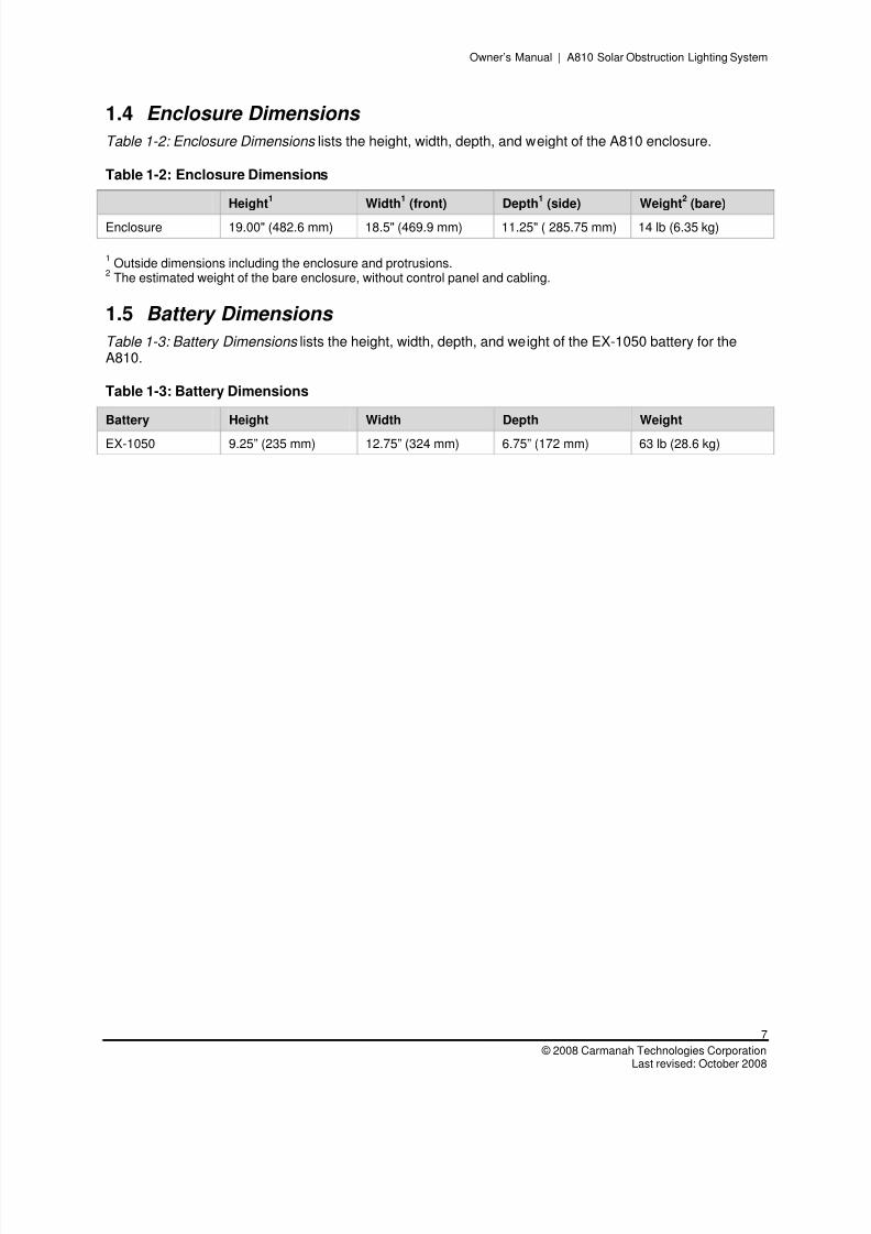
1.4 Enclosure Dimensions
Table 1-2: Enclosure Dimensions lists the height, width, depth, and weight of the A810 enclosure.
Table 1-2: Enclosure Dimensions
Height1
Width1
(front) Depth1
(side) Weight2
(bare)
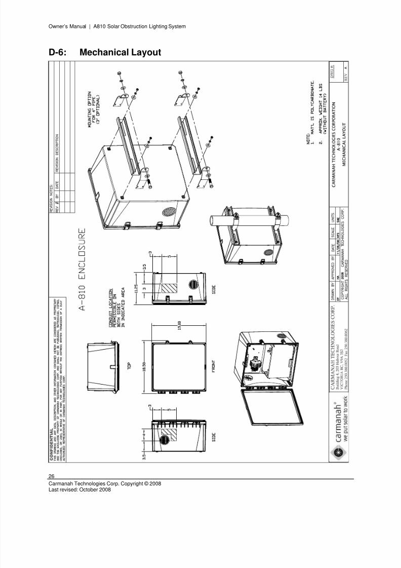
Enclosure 19.00" (482.6 mm) 18.5" (469.9 mm) 11.25" ( 285.75 mm) 14 lb (6.35 kg)
1Outside dimensions including the enclosure and protrusions.
2The estimated weight of the bare enclosure, without control panel and cabling.
1.5 Battery Dimensions
Table 1-3: Battery Dimensions lists the height, width, depth, and weight of the EX-1050 battery for theA810.
Table 1-3: Battery Dimensions
Battery Height Width Depth Weight
EX-1050 9.25” (235 mm) 12.75” (324 mm) 6.75” (172 mm) 63 lb (28.6 kg)
8/3/2019 A810 Manual Carmanah
http://slidepdf.com/reader/full/a810-manual-carmanah 8/28
Owner’s Manual | A810 Solar Obstruction Lighting System
8
Carmanah Technologies Corp. Copyright © 2008Last revised: October 2008
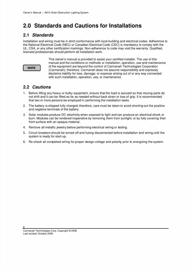
2.0 Standards and Cautions for Installations
2.1 Standards
Installation and wiring must be in strict conformance with local building and electrical codes. Adherence tothe National Electrical Code (NEC) or Canadian Electrical Code (CEC) is mandatory to comply with the
UL, CSA, or any other certification markings. Non-adherence to code may void the warranty. Qualified,licensed professionals should perform all installation work.
This owner’s manual is provided to assist your certified installer. The use of thismanual and the conditions or methods or installation, operation, use and maintenanceof the equipment are beyond the control of Carmanah Technologies Corporation(Carmanah); therefore, Carmanah does not assume responsibility and expresslydisclaims liability for loss, damage, or expense arising out of or any way connectedwith such installation, operation, use, or maintenance.
2.2 Cautions
1. Before lifting any heavy or bulky equipment, ensure that the load is secured so that moving parts donot shift and it can be lifted as far as needed without back strain or loss of grip. It is recommendedthat two or more persons be employed in performing the installation tasks.
2. The battery is shipped fully charged; therefore, care must be taken to avoid shorting out the positiveand negative terminals of the battery.
3. Solar modules produce DC electricity when exposed to light and can produce an electrical shock orburn. Modules can be rendered inoperative by removing them from sunlight, or by fully covering theirfront surface with an opaque material.
4. Remove all metallic jewelry before performing electrical wiring or testing.
5. Circuit breakers should be turned off and fusing disconnected before installation and wiring until thesystem is ready for start-up.
6. Re-check all completed wiring for proper design voltage and polarity prior to energizing the system.
8/3/2019 A810 Manual Carmanah
http://slidepdf.com/reader/full/a810-manual-carmanah 9/28
Owner’s Manual | A810 Solar Obstruction Lighting System
9
© 2008 Carmanah Technologies CorporationLast revised: October 2008
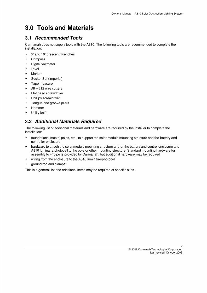
3.0 Tools and Materials
3.1 Recommended Tools
Carmanah does not supply tools with the A810. The following tools are recommended to complete theinstallation:
6” and 10” crescent wrenches
Compass
Digital voltmeter
Level
Marker
Socket Set (Imperial)
Tape measure
#8 – #12 wire cutters
Flat head screwdriver
Phillips screwdriver
Tongue and groove pliers Hammer
Utility knife
3.2 Additional Materials Required
The following list of additional materials and hardware are required by the installer to complete theinstallation:
foundations, masts, poles, etc., to support the solar module mounting structure and the battery andcontroller enclosure
hardware to attach the solar module mounting structure and or the battery and control enclosure andA810 luminaire/photocell to the pole or other mounting structure. Standard mounting hardware for
assembly to 4” pipe is provided by Carmanah, but additional hardware may be required wiring from the enclosure to the A810 luminaire/photocell
ground rod and clamps
This is a general list and additional items may be required at specific sites.
8/3/2019 A810 Manual Carmanah
http://slidepdf.com/reader/full/a810-manual-carmanah 10/28
Owner’s Manual | A810 Solar Obstruction Lighting System
10
Carmanah Technologies Corp. Copyright © 2008Last revised: October 2008
4.0 Solar Array and Mounting Structure
4.1 Array Orientation
Full solar exposure is critical to the performance of the A810. Ensure that the solar module installationlocation has year-round, unrestricted sun exposure throughout the day. If required, the solar array may be
attached remotely to the battery using an appropriately sized transmission cable. The bottom edge of thesolar modules should be installed at a minimum height to clear growing vegetation and snow at the site.
Shading even a small portion of the solar module will significantly reduce the output ofthe A810.
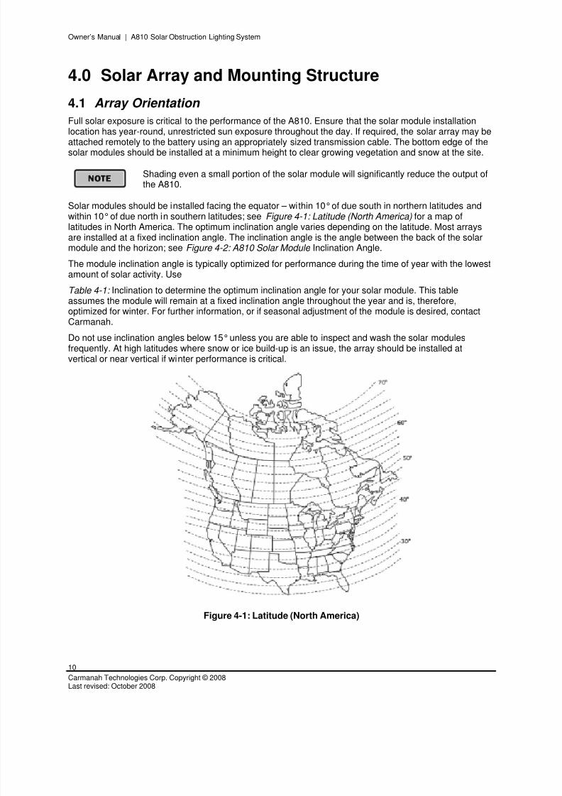
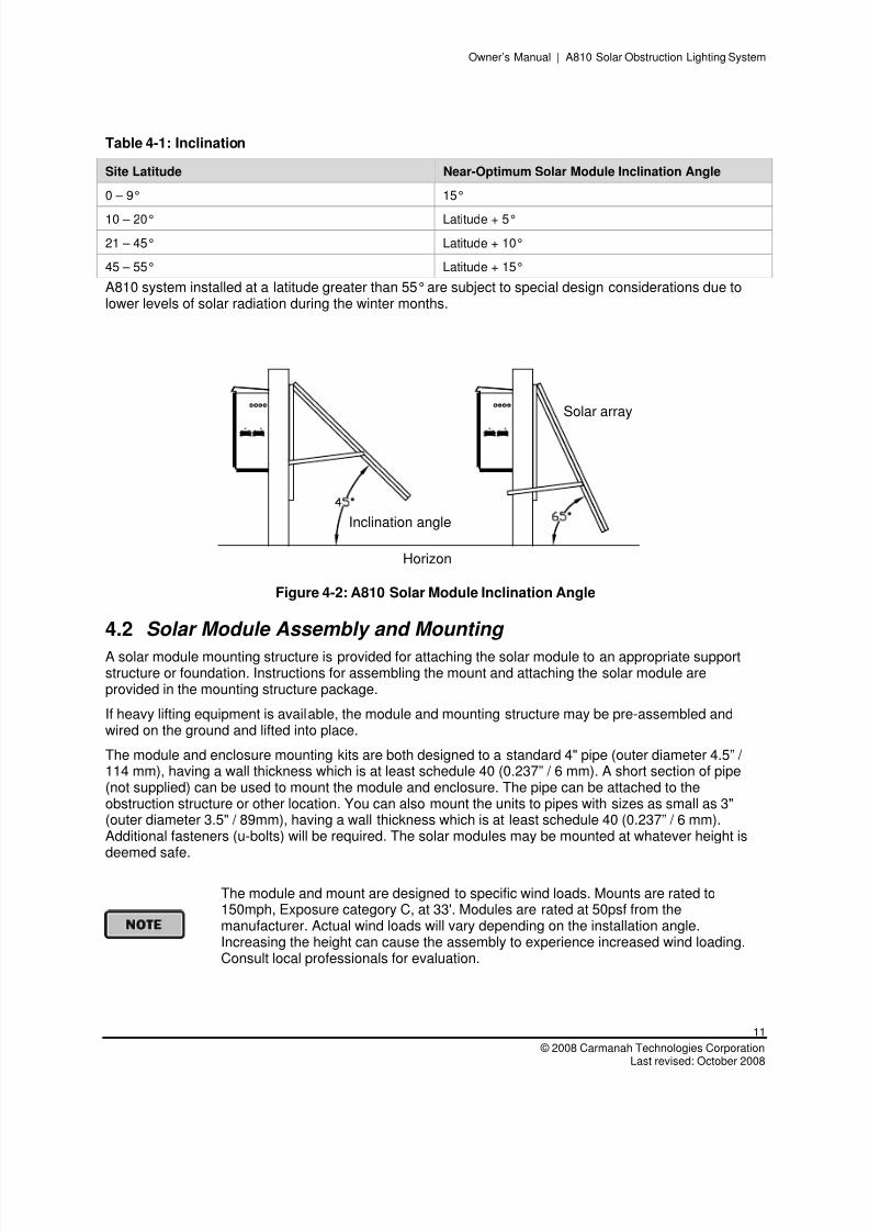
Solar modules should be installed facing the equator – within 10° of due south in northern latitudes andwithin 10° of due north in southern latitudes; see Figure 4-1: Latitude (North America) for a map oflatitudes in North America. The optimum inclination angle varies depending on the latitude. Most arraysare installed at a fixed inclination angle. The inclination angle is the angle between the back of the solarmodule and the horizon; see Figure 4-2: A810 Solar Module Inclination Angle.
The module inclination angle is typically optimized for performance during the time of year with the lowest
amount of solar activity. UseTable 4-1: Inclination to determine the optimum inclination angle for your solar module. This tableassumes the module will remain at a fixed inclination angle throughout the year and is, therefore,optimized for winter. For further information, or if seasonal adjustment of the module is desired, contactCarmanah.
Do not use inclination angles below 15° unless you are able to inspect and wash the solar modulesfrequently. At high latitudes where snow or ice build-up is an issue, the array should be installed atvertical or near vertical if winter performance is critical.
Figure 4-1: Latitude (North America)
8/3/2019 A810 Manual Carmanah
http://slidepdf.com/reader/full/a810-manual-carmanah 11/28
Owner’s Manual | A810 Solar Obstruction Lighting System
11
© 2008 Carmanah Technologies CorporationLast revised: October 2008
Table 4-1: Inclination
Site Latitude Near-Optimum Solar Module Inclination Angle
0 – 9° 15°
10 – 20° Latitude + 5°
21 – 45° Latitude + 10°
45 – 55° Latitude + 15°
A810 system installed at a latitude greater than 55° are subject to special design considerations due tolower levels of solar radiation during the winter months.
Horizon
Inclination angle
Solar array
Figure 4-2: A810 Solar Module Inclination Angle
4.2 Solar Module Assembly and Mounting
A solar module mounting structure is provided for attaching the solar module to an appropriate supportstructure or foundation. Instructions for assembling the mount and attaching the solar module areprovided in the mounting structure package.
If heavy lifting equipment is available, the module and mounting structure may be pre-assembled andwired on the ground and lifted into place.
The module and enclosure mounting kits are both designed to a standard 4" pipe (outer diameter 4.5” / 114 mm), having a wall thickness which is at least schedule 40 (0.237” / 6 mm). A short section of pipe(not supplied) can be used to mount the module and enclosure. The pipe can be attached to theobstruction structure or other location. You can also mount the units to pipes with sizes as small as 3"(outer diameter 3.5" / 89mm), having a wall thickness which is at least schedule 40 (0.237” / 6 mm).Additional fasteners (u-bolts) will be required. The solar modules may be mounted at whatever height isdeemed safe.
The module and mount are designed to specific wind loads. Mounts are rated to150mph, Exposure category C, at 33'. Modules are rated at 50psf from themanufacturer. Actual wind loads will vary depending on the installation angle. Increasing the height can cause the assembly to experience increased wind loading.Consult local professionals for evaluation.
8/3/2019 A810 Manual Carmanah
http://slidepdf.com/reader/full/a810-manual-carmanah 12/28
Owner’s Manual | A810 Solar Obstruction Lighting System
12
Carmanah Technologies Corp. Copyright © 2008Last revised: October 2008
The following is the recommended torques for fasteners:
Fastener Size Torque Imperial Torque Metric
1/4 – 20 40 – 50 lbf·in (4.5 - 5.6 N·m)
5/16 – 18 8 – 10 lbf·ft (10.8 – 13.6 N·m)
3/8 – 16 14 – 16 lbf·ft (19.0 – 21.7 N·m)
Array Wiring 1. Refer to the included Wiring Diagram addendum for the type of solar module for your system.
2. All wiring must be performed according to NEC or CEC code requirements.
3. To ensure compliance with local electrical code, use the conduit, connectors and wire from thesupplied wiring kit.
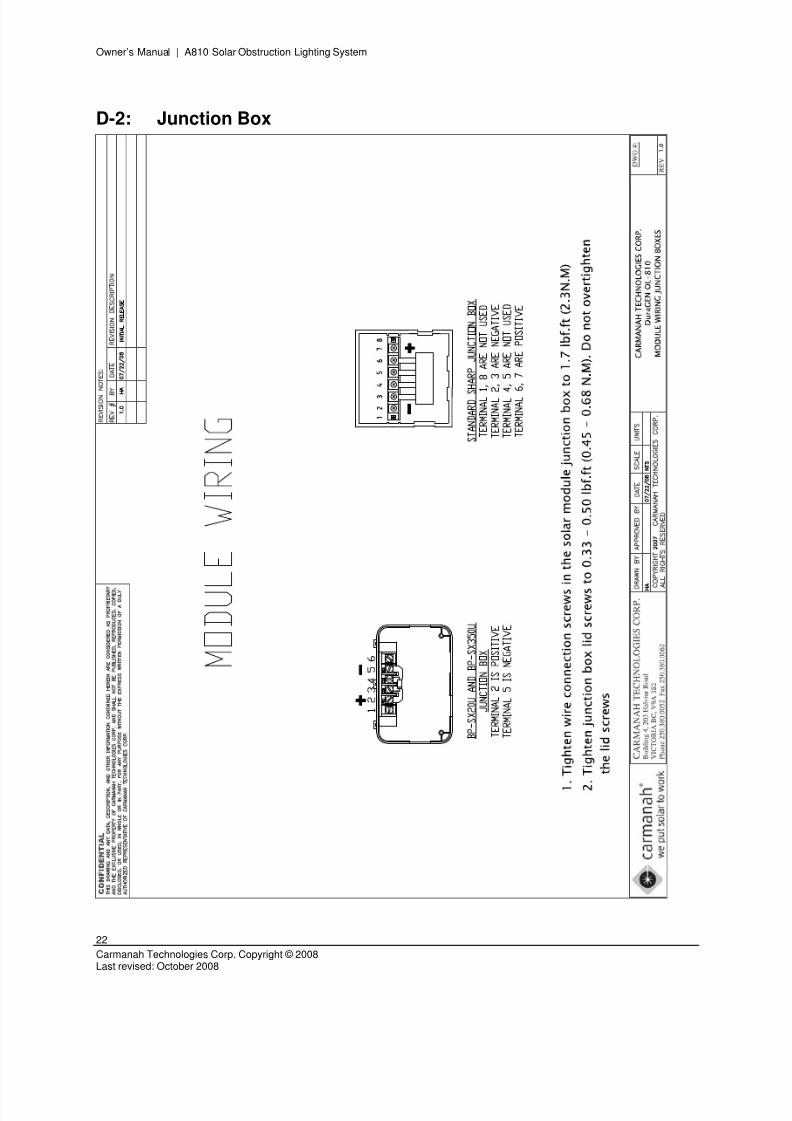
4. Tighten wire connection screws in the solar module junction box to 1.7 lbf·ft (2.3 N·m).
5. Tighten junction box lid screws to 0.33 – 0.50 lbf·ft (0.45 – 0.68 N·m). Do not overtighten the lidscrews.
The solar modules are provided with conduit-ready junction boxes. The diagrams in the included WiringDiagram addendum contain generic junction box schematics to illustrate the typical interconnections andwire routing for a 12 V A810. Some modules have different arrangements of positive, negative, andfloating terminals; see a 12 volt A810 Appendix D-2: Junction Box for specific details. Do not connectmore than two wires to any module terminal.
4.3 Grounding and Lightning Protection
Failure to install and connect an appropriate grounding system will greatly increase therisk of system damage by lightning strikes.
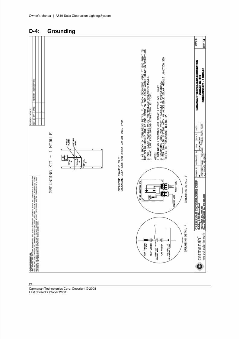
Surges resulting from lightning strikes in the proximity of the installation are one of the most commoncauses of solar system failure. Installation of a proper ground system allows the static electricity thataccumulates in the module and mounting structure to discharge. In addition to preventing the attraction oflightning, a properly grounded installation may divert the surge associated with lightning from electricalcircuitry, limiting the potential for damage. An equipment grounding kit is included with the A810. See Appendix D-4: Grounding . System grounding is the responsibility of the installer.
Grounding techniques vary depending on site specifics. Consultation with a local grounding expert isrecommended.
8/3/2019 A810 Manual Carmanah
http://slidepdf.com/reader/full/a810-manual-carmanah 13/28
Owner’s Manual | A810 Solar Obstruction Lighting System
13
© 2008 Carmanah Technologies CorporationLast revised: October 2008
5.0 Battery and Control Enclosure
5.1 Enclosure Description
The A810 solar engine battery enclosure houses the battery and pre-installed control panel.
This product is designed for use with the A810 luminaire only. Other loads may cause areduction in the number of days of autonomy or lead to system failure.
Depending on the mounting options chosen, the user can mount the enclosure to the side of a pole, wall,or base foundation. See Appendix D-6: Mechanical Layout for other options.
5.2 Enclosure Preparation
Prior to mounting the enclosure, prepare all conduit and wiring requirements as described below.
Enclosure Preparation Instructions
1. Drill appropriate hole for the module wires; see Appendix C: Recommended Hole Location.
2. Drill appropriate hole for the A810 luminaire conduit; see Appendix C: Recommended Hole Location.
3. Attach the enclosure mounting options.
4. Secure all wires and remove loose objects from inside the enclosure. Close the door prior tomounting.
5.3 Mounting the Enclosure
The enclosure should be lifted and mounted by two people. When pre-installing the battery, ensure that itis strapped down to prevent it from shifting or falling out. Attachment clamps for a standard 4" pipe (outdiameter 4.5"/114mm, schedule 40) are provided with the enclosures for attaching to a circular pole.
User supplied hardware is required if the enclosure is attached to a square pole or other
structure. If the enclosure is mounted at ground level, there may be local regulationswhich specify certain conditions for installation. For more information, consult with therelevant local governing bodies before installation. See local regulations. For vandalismsuggestions, See Section 4.2 Solar Module Assembly and Mounting.
The following is the recommended torques for fasteners:
Fastener Size Torque Imperial Torque Metric
#10 – 16 3 – 4 lbf·in (34 – 45 N·m)
1/4 – 20 40 – 50 lbf·in (4.5 – 5.6 N·m)
5/16 – 18 8 – 10 lbf·ft (10.8 – 13.6 N·m)
8/3/2019 A810 Manual Carmanah
http://slidepdf.com/reader/full/a810-manual-carmanah 14/28
8/3/2019 A810 Manual Carmanah
http://slidepdf.com/reader/full/a810-manual-carmanah 15/28
Owner’s Manual | A810 Solar Obstruction Lighting System
15
© 2008 Carmanah Technologies CorporationLast revised: October 2008
7.0 Luminaire and Photocell Installation
7.1 Installing the Luminaire
Installation instructions are included with the A810 light. See Appendix D-1: Wiring Schematic.
7.2 Mounting the Luminaire
The A810 luminaire comes with a bottom hub, including a 1” (25.4 mm) NPT port and a ¾” (19.05 mm)NPT bushing for mounting. The A810 luminaire must be mounted vertically; failure to do so will result inthe luminaire not meeting optical requirements.
7.3 Height Restrictions
The distances listed in Table 7.1 are the maximum recommended distances from the luminaire to theenclosure with the recommended minimum wire gauge to ensure proper operation of the A810 luminaire.
Table 7.1: Distance and Wire Gauge
Distance between luminaire and enclosure Minimum wire gauge375 to 450 ft (114 to 137 m) #8 (8 AWG)
250 to 375 ft (76 to 114 m) #10 (10 AWG)
0 to 250 ft (0 to 76 m) #12 (12 AWG)
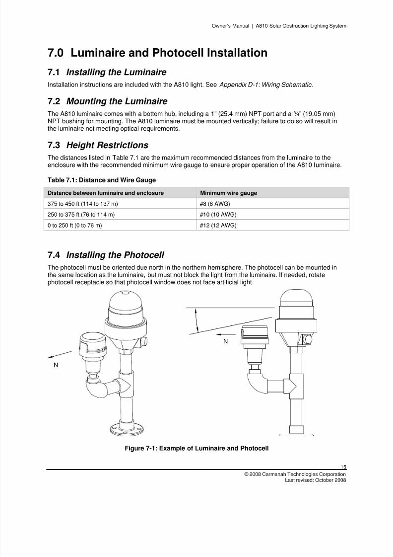
7.4 Installing the Photocell
The photocell must be oriented due north in the northern hemisphere. The photocell can be mounted inthe same location as the luminaire, but must not block the light from the luminaire. If needed, rotatephotocell receptacle so that photocell window does not face artificial light.
N
N
Figure 7-1: Example of Luminaire and Photocell
8/3/2019 A810 Manual Carmanah
http://slidepdf.com/reader/full/a810-manual-carmanah 16/28
Owner’s Manual | A810 Solar Obstruction Lighting System
16
Carmanah Technologies Corp. Copyright © 2008Last revised: October 2008
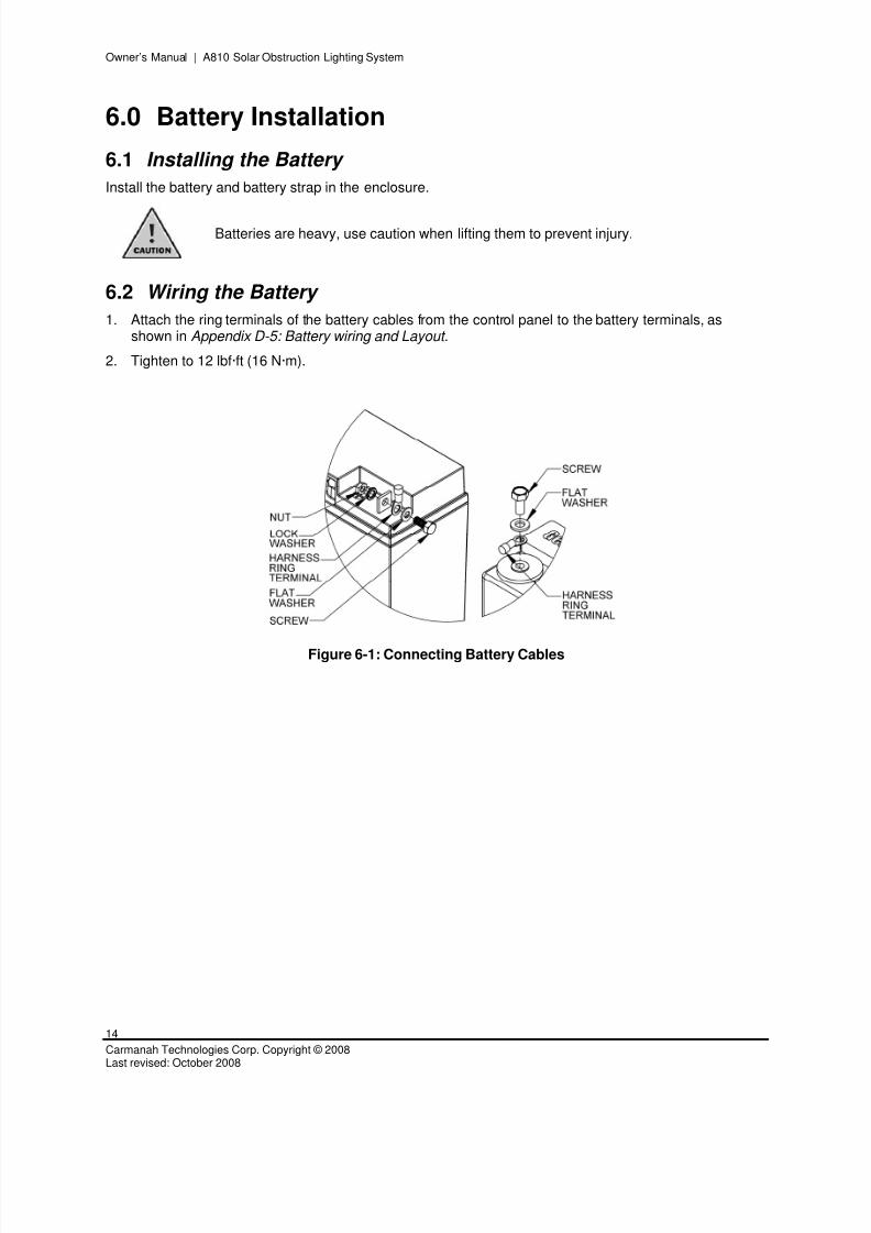
8.0 Control Panel Wiring
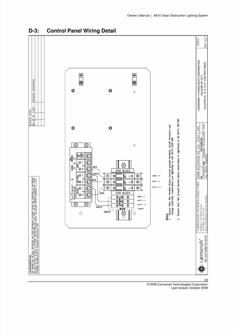
Ensure that the terminal block connections (except the ground terminal) are tightened to 1.67 lbf·ft (2.26N·m). Tighten the ground terminal block connection to 0.6 lbf·ft (0.8 N·m).
See Appendix D-3: Control Panel Wiring Detail for the control panel wiring diagram.
8.1 Wiring the Control Panel
1. To avoid equipment damage, ensure all circuit breakers are in the OFF position.
2. Connect the module wires to the control panel ARRAY terminals
3. Route the L-810 luminaire/photocell wires into the control compartment using conduit and strain reliefconnectors. Connect the luminaire/photocell wiring; see Appendix D: D-3: Control Panel Wiring Detail .
4. Connect the bare copper ground wire to the ground terminal on the control panel.
This product is designed for use with the A810 luminaire only. Any other loads maycause a reduction in the number of days of autonomy or lead to system failure.
8/3/2019 A810 Manual Carmanah
http://slidepdf.com/reader/full/a810-manual-carmanah 17/28
Owner’s Manual | A810 Solar Obstruction Lighting System
17
© 2008 Carmanah Technologies CorporationLast revised: October 2008
9.0 System Operation
9.1 System Check and Start-up
Prior to turning the system on, check all wiring and connections to ensure the wires are correctly placed,the polarities are correct, and wires are secured. Check the attachments of the mounting structure and
battery enclosure to the pole or mounting surface.
Energize the system by turning on the circuit breakers in the following order:
1. Battery
2. Array
3. Load
The charging light of the charge controller should turn on. Although the charging current falls to very lowlevels when the battery reaches full charge, the light will continue to stay on all day. This is to indicate thatthe controller is working and that energy is available from the PV module for charging (the light will turnoff at night). The Low Voltage Disconnect light should be off. If it is on, indicating the controller is in LoadDisconnect, disconnect the load, and disconnect then reconnect the battery circuit to reset the load relayand turn off the light. If the Low Voltage Disconnect light remains on, the battery charge state is low and
should be recharged before completing the installation. If the charging light does not turn on at all, refer tothe troubleshooting section of the controller manual. Turn on the load equipment as required.
9.2 Principles of Operation
The A810 operates automatically with no need for operator interaction under normal conditions. Withnormal daylight illumination, the solar module is capable of producing sufficient current to charge thebattery. The charging light indicates the battery is being charged by the solar module.
If the battery discharges to the pre-set load disconnect voltage due to long periods of poor weather, thelow voltage disconnect (LVD) relay is activated, the red LED turns on, and the L-810 luminaire isdisconnected. Disconnecting the L-810 luminaire prevents battery damage associated with completedischarge of the battery. The Red LED will turn off when the battery recovers to about 50% of its ratedcapacity and the luminaire is automatically reconnected.
9.3 Maintenance
Proper maintenance of this system is vital for long term, reliable operation. A quarterly inspection (ie:once every four months) is recommended for the solar modules, battery, luminaire/photocell and controls.
Maintenance should include a general inspection to check for any wear due to the elements, for example,sun, wind, rain, etc. All connections should be checked to ensure that they are secure.
Depending on local conditions, the solar modules may require periodic cleaning. Solar modules with tiltangles less than 20° may require more frequent cleaning. Dust, if allowed to accumulate, will reduce thepower output of the solar modules.
Sealed AGM batteries require no maintenance, but the user should inspect the battery for bulging orcracks.
Check the enclosure and electronic components for signs of water intrusion or condensation damage. Nosignificant water should accumulate in the sealed control compartment.
Annually, all electrical and mechanical connections should be tightened to the proper torque specification,even if they appear sound.
8/3/2019 A810 Manual Carmanah
http://slidepdf.com/reader/full/a810-manual-carmanah 18/28
Owner’s Manual | A810 Solar Obstruction Lighting System
18
Carmanah Technologies Corp. Copyright © 2008Last revised: October 2008
Appendix A: Warranty and Customer Service
A-1: Warranty
This product is covered by the Carmanah warranty. Visit www.carmanah.com/content/products/warranty/ for additional information or to register your product online.
A-2: Customer Service
Before contacting Carmanah’s customer service department, please have the A810 serial or identificationnumbers available, proof of purchase, and details on the location and nature of the failure.
To contact Carmanah’s Customer Service Department:
Mail: Carmanah Technologies CorporationBuilding 4 – 203 Harbour RoadVictoria, BC Canada V9A 3S2
Phone: 1.250.380.00521.877.722.8877 (Toll Free in U.S. and Canada)
Fax: 1.250.380.0062Email: [email protected]
Website: carmanah.com
A-3: 12 Month Limited Warranty
The following items apply in addition to the standard Carmanah 12 Month Limited warranty.
1. Carmanah warrants the A810 for a period of 12 months from the date of shipment from its factory.This warranty is valid against defects in materials and workmanship for the 12 month warranty period.It is not valid against defects resulting from, but not limited to:
Misuse, abuse, neglect or accident.
Exceeding the unit’s design limits.
Improper installation including, but not limited to, improper environmental protection and improperhook-up.
Acts of God, including lightning, floods, earthquakes, fire, and high winds.
Damage in handling, including damage encountered during shipment.
2. This warranty shall be considered void if the warranted product is in any way opened or altered. Thewarranty will be void if any eyelet, rivets, or other fasteners used to seal the unit are removed oraltered, or if the unit’s serial number is in any way removed, altered, replaced, defaced, or renderedillegible.
3. The 12 month term of this warranty does not apply to equipment where another manufacturers’warranty is available.
8/3/2019 A810 Manual Carmanah
http://slidepdf.com/reader/full/a810-manual-carmanah 19/28
Owner’s Manual | A810 Solar Obstruction Lighting System
19
© 2008 Carmanah Technologies CorporationLast revised: October 2008
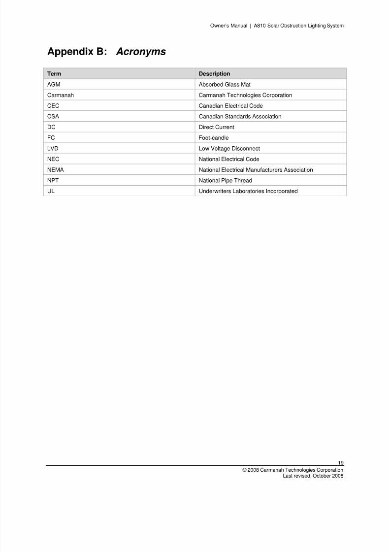
Appendix B: Acronyms
Term Description
AGM Absorbed Glass Mat
Carmanah Carmanah Technologies CorporationCEC Canadian Electrical Code
CSA Canadian Standards Association
DC Direct Current
FC Foot-candle
LVD Low Voltage Disconnect
NEC National Electrical Code
NEMA National Electrical Manufacturers Association
NPT National Pipe Thread
UL Underwriters Laboratories Incorporated
8/3/2019 A810 Manual Carmanah
http://slidepdf.com/reader/full/a810-manual-carmanah 20/28
Owner’s Manual | A810 Solar Obstruction Lighting System
20
Carmanah Technologies Corp. Copyright © 2008Last revised: October 2008
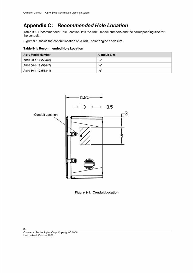
Appendix C: Recommended Hole Location Table 9-1: Recommended Hole Location lists the A810 model numbers and the corresponding size forthe conduit.
Figure 9-1 shows the conduit location on a A810 solar engine enclosure.
Table 9-1: Recommended Hole Location
A810 Model Number Conduit Size
A810 20-1-12 (58448) ½”
A810 50-1-12 (58447) ½”
A810 80-1-12 (58341) ½”
Figure 9-1: Conduit Location
Conduit Location
8/3/2019 A810 Manual Carmanah
http://slidepdf.com/reader/full/a810-manual-carmanah 21/28
Owner’s Manual | A810 Solar Obstruction Lighting System
21
© 2008 Carmanah Technologies CorporationLast revised: October 2008
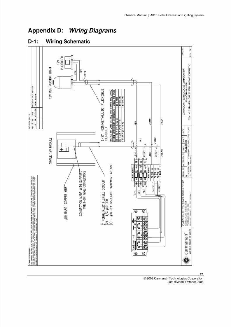
Appendix D: Wiring Diagrams
D-1: Wiring Schematic
8/3/2019 A810 Manual Carmanah
http://slidepdf.com/reader/full/a810-manual-carmanah 22/28
Owner’s Manual | A810 Solar Obstruction Lighting System
22
Carmanah Technologies Corp. Copyright © 2008Last revised: October 2008
D-2: Junction Box
8/3/2019 A810 Manual Carmanah
http://slidepdf.com/reader/full/a810-manual-carmanah 23/28
Owner’s Manual | A810 Solar Obstruction Lighting System
23
© 2008 Carmanah Technologies CorporationLast revised: October 2008
D-3: Control Panel Wiring Detail
8/3/2019 A810 Manual Carmanah
http://slidepdf.com/reader/full/a810-manual-carmanah 24/28
Owner’s Manual | A810 Solar Obstruction Lighting System
24
Carmanah Technologies Corp. Copyright © 2008Last revised: October 2008
D-4: Grounding
8/3/2019 A810 Manual Carmanah
http://slidepdf.com/reader/full/a810-manual-carmanah 25/28
Owner’s Manual | A810 Solar Obstruction Lighting System
25
© 2008 Carmanah Technologies CorporationLast revised: October 2008
D-5: Battery Wiring and Layout
8/3/2019 A810 Manual Carmanah
http://slidepdf.com/reader/full/a810-manual-carmanah 26/28
Owner’s Manual | A810 Solar Obstruction Lighting System
26
Carmanah Technologies Corp. Copyright © 2008Last revised: October 2008
D-6: Mechanical Layout

8/3/2019 A810 Manual Carmanah
http://slidepdf.com/reader/full/a810-manual-carmanah 27/28

8/3/2019 A810 Manual Carmanah
http://slidepdf.com/reader/full/a810-manual-carmanah 28/28
© 2008 Carmanah Technologies Corporationwww.carmanah.com
Technical Support: [email protected] Free in Canada and the U.S.: 1.877.722.8877
International: 1.250.380.0052 | Fax: 1.250.380.0062
Number: 57161_A810_Manual_RevA
57161