PAPI Solar Module User Manual - Carmanah
26
OPERATOR'S AND MAINTENANCE MANUAL (INCLUDING REPAIR PARTS AND SPECIAL TOOLS LIST) PORTABLE SOLAR MODULE for PRECISION APPROACH PATH INDICATOR Model CT-675 Technical Support: Email: [email protected] Toll Free: 1.877.722.8877 (US & Canada) Worldwide: 1.250.380.0052 Fax: 1.250.380.0062 Web: carmanah.com DISTRIBUTION STATEMENT A - Approved for public release; distribution is unlimited. 15 May 2012
Transcript of PAPI Solar Module User Manual - Carmanah
OPERATOR'S AND MAINTENANCE MANUAL (INCLUDING REPAIR PARTS AND SPECIAL TOOLS LIST)
PORTABLE SOLAR MODULE for
PRECISION APPROACH PATH INDICATOR
Model CT-675
Technical Support: Email: [email protected] Toll Free: 1.877.722.8877 (US & Canada) Worldwide: 1.250.380.0052 Fax: 1.250.380.0062 Web: carmanah.com
DISTRIBUTION STATEMENT A - Approved for public release; distribution is unlimited.
15 May 2012

THIS PAGE INTENTIONALLY BLANK
D-040: AVIA Guide PAPI Solar Module
iii
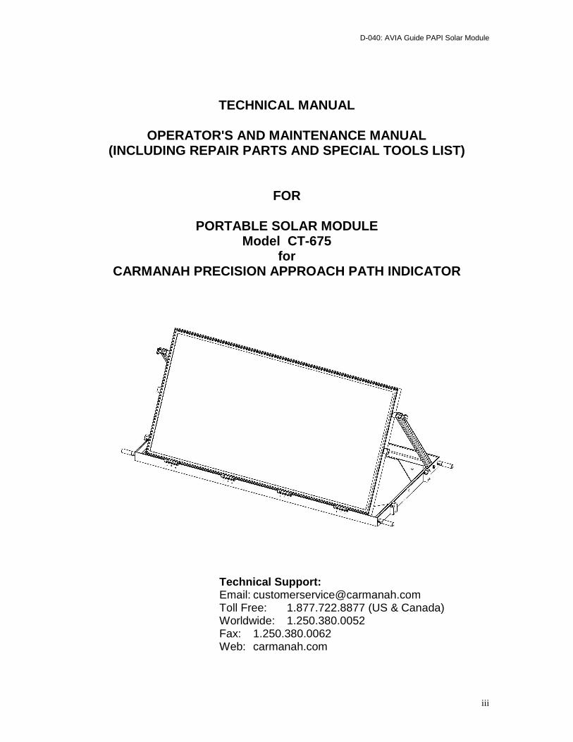
TECHNICAL MANUAL
OPERATOR'S AND MAINTENANCE MANUAL (INCLUDING REPAIR PARTS AND SPECIAL TOOLS LIST)
FOR
PORTABLE SOLAR MODULE Model CT-675
for CARMANAH PRECISION APPROACH PATH INDICATOR
Technical Support: Email: [email protected] Toll Free: 1.877.722.8877 (US & Canada) Worldwide: 1.250.380.0052 Fax: 1.250.380.0062 Web: carmanah.com
D-040: AVIA Guide PAPI Solar Module
iv
WARNING SUMMARY HANDLING The Solar Arrays contain glass components. Care should be taken to avoid unnecessary shock. Do not drop. The Solar Array is designed to be transported in the horizontal position in its case. DO NOT STEP on the top of the Solar Arrays. IMPROPER CLEANING AGENTS Improper cleaning methods and use of unauthorized cleaning agents can injure personnel and damage equipment.
D-040: AVIA Guide PAPI Solar Module
v
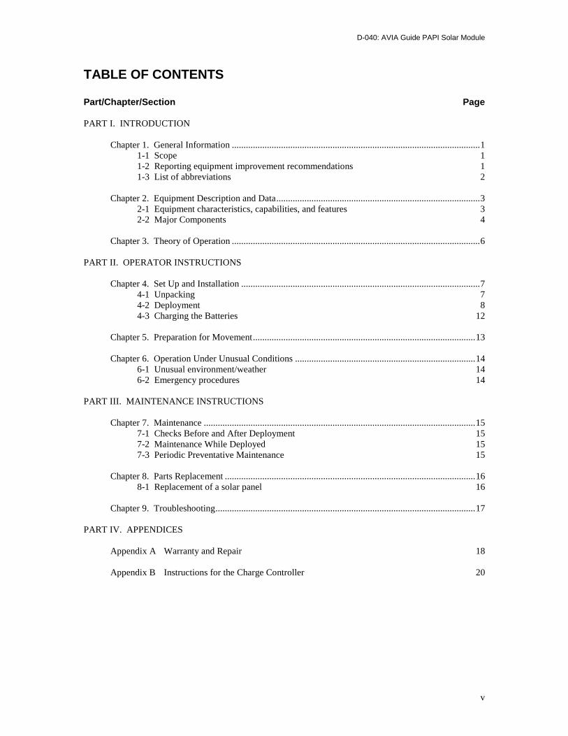
TABLE OF CONTENTS Part/Chapter/Section Page PART I. INTRODUCTION Chapter 1. General Information .......................................................................................................... 1 1-1 Scope 1 1-2 Reporting equipment improvement recommendations 1 1-3 List of abbreviations 2 Chapter 2. Equipment Description and Data ....................................................................................... 3 2-1 Equipment characteristics, capabilities, and features 3 2-2 Major Components 4 Chapter 3. Theory of Operation .......................................................................................................... 6 PART II. OPERATOR INSTRUCTIONS Chapter 4. Set Up and Installation ...................................................................................................... 7 4-1 Unpacking 7 4-2 Deployment 8 4-3 Charging the Batteries 12 Chapter 5. Preparation for Movement ............................................................................................... 13 Chapter 6. Operation Under Unusual Conditions ............................................................................. 14 6-1 Unusual environment/weather 14 6-2 Emergency procedures 14 PART III. MAINTENANCE INSTRUCTIONS Chapter 7. Maintenance .................................................................................................................... 15 7-1 Checks Before and After Deployment 15 7-2 Maintenance While Deployed 15 7-3 Periodic Preventative Maintenance 15 Chapter 8. Parts Replacement ........................................................................................................... 16 8-1 Replacement of a solar panel 16 Chapter 9. Troubleshooting ............................................................................................................... 17 PART IV. APPENDICES Appendix A Warranty and Repair 18 Appendix B Instructions for the Charge Controller 20
D-040: AVIA Guide PAPI Solar Module
- 1 -
Chapter 1. General Information 1-1 Scope a. Type of manual: Operator's Manual. b. Model number and equipment names: Portable Solar Module model CT-675 c. Purpose of equipment: portable solar power can be directly connected to the portable PAPI d. Location terms: Throughout this manual, the terms “front”, “rear”, “top”, “bottom”,
“starboard side”, and “port side” are used to describe the views of the portable solar modules. The glass surfaces of the solar cells are located on the front panel. The port side is the side to the left when looking at the front, and the starboard side is the side to the right when looking at the front.
1-2 Reporting Equipment Improvement Recommendations If you have recommends for improvement, please let us know. You, the user, are the only one who can tell us what you don't like about your equipment. If you have feedback on a Carmanah Aviation product, please contact us at [email protected].
D-040: AVIA Guide PAPI Solar Module
- 2 -
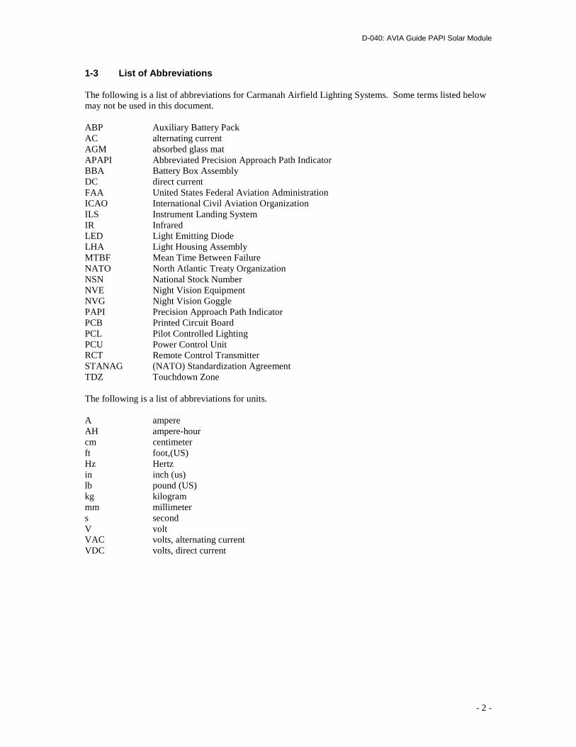
1-3 List of Abbreviations The following is a list of abbreviations for Carmanah Airfield Lighting Systems. Some terms listed below may not be used in this document. ABP Auxiliary Battery Pack AC alternating current AGM absorbed glass mat APAPI Abbreviated Precision Approach Path Indicator BBA Battery Box Assembly DC direct current FAA United States Federal Aviation Administration ICAO International Civil Aviation Organization ILS Instrument Landing System IR Infrared LED Light Emitting Diode LHA Light Housing Assembly MTBF Mean Time Between Failure NATO North Atlantic Treaty Organization NSN National Stock Number NVE Night Vision Equipment NVG Night Vision Goggle PAPI Precision Approach Path Indicator PCB Printed Circuit Board PCL Pilot Controlled Lighting PCU Power Control Unit RCT Remote Control Transmitter STANAG (NATO) Standardization Agreement TDZ Touchdown Zone The following is a list of abbreviations for units. A ampere AH ampere-hour cm centimeter ft foot,(US) Hz Hertz in inch (us) lb pound (US) kg kilogram mm millimeter s second V volt VAC volts, alternating current VDC volts, direct current
D-040: AVIA Guide PAPI Solar Module
- 3 -
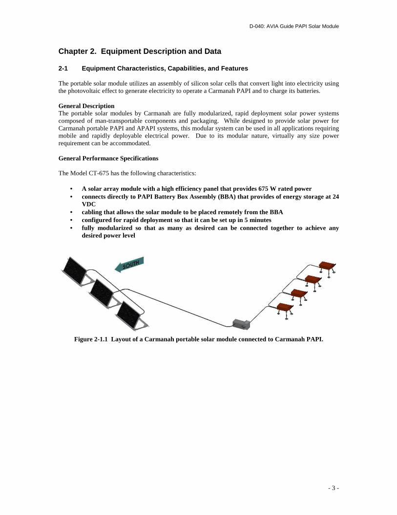
Chapter 2. Equipment Description and Data 2-1 Equipment Characteristics, Capabilities, and Fe atures The portable solar module utilizes an assembly of silicon solar cells that convert light into electricity using the photovoltaic effect to generate electricity to operate a Carmanah PAPI and to charge its batteries. General Description The portable solar modules by Carmanah are fully modularized, rapid deployment solar power systems composed of man-transportable components and packaging. While designed to provide solar power for Carmanah portable PAPI and APAPI systems, this modular system can be used in all applications requiring mobile and rapidly deployable electrical power. Due to its modular nature, virtually any size power requirement can be accommodated. General Performance Specifications The Model CT-675 has the following characteristics:
• A solar array module with a high efficiency panel that provides 675 W rated power • connects directly to PAPI Battery Box Assembly (BBA) that provides of energy storage at 24
VDC • cabling that allows the solar module to be placed remotely from the BBA • configured for rapid deployment so that it can be set up in 5 minutes • fully modularized so that as many as desired can be connected together to achieve any
desired power level
Figure 2-1.1 Layout of a Carmanah portable solar module connected to Carmanah PAPI.
D-040: AVIA Guide PAPI Solar Module
- 4 -
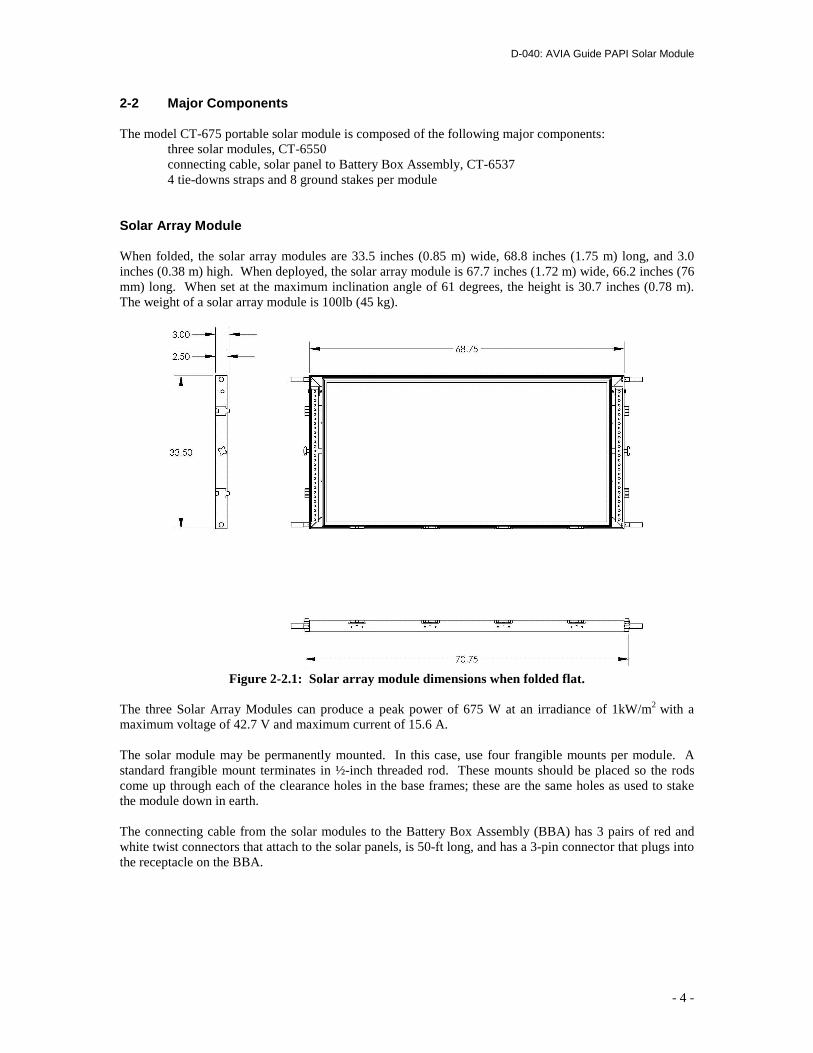
2-2 Major Components The model CT-675 portable solar module is composed of the following major components: three solar modules, CT-6550 connecting cable, solar panel to Battery Box Assembly, CT-6537 4 tie-downs straps and 8 ground stakes per module Solar Array Module When folded, the solar array modules are 33.5 inches (0.85 m) wide, 68.8 inches (1.75 m) long, and 3.0 inches (0.38 m) high. When deployed, the solar array module is 67.7 inches (1.72 m) wide, 66.2 inches (76 mm) long. When set at the maximum inclination angle of 61 degrees, the height is 30.7 inches (0.78 m). The weight of a solar array module is 100lb (45 kg).
Figure 2-2.1: Solar array module dimensions when folded flat.
The three Solar Array Modules can produce a peak power of 675 W at an irradiance of 1kW/m2 with a maximum voltage of 42.7 V and maximum current of 15.6 A. The solar module may be permanently mounted. In this case, use four frangible mounts per module. A standard frangible mount terminates in ½-inch threaded rod. These mounts should be placed so the rods come up through each of the clearance holes in the base frames; these are the same holes as used to stake the module down in earth. The connecting cable from the solar modules to the Battery Box Assembly (BBA) has 3 pairs of red and white twist connectors that attach to the solar panels, is 50-ft long, and has a 3-pin connector that plugs into the receptacle on the BBA.
D-040: AVIA Guide PAPI Solar Module
- 5 -
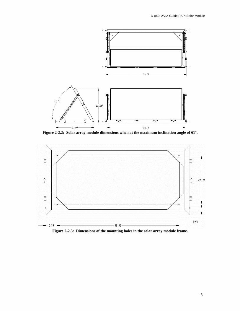
Figure 2-2.2: Solar array module dimensions when at the maximum inclination angle of 61°.
Figure 2-2.3: Dimensions of the mounting holes in the solar array module frame.
D-040: AVIA Guide PAPI Solar Module
- 6 -
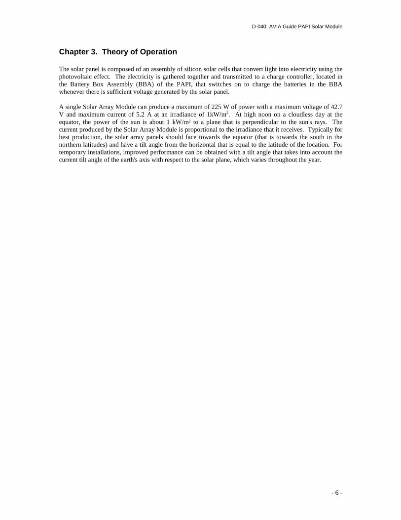
Chapter 3. Theory of Operation The solar panel is composed of an assembly of silicon solar cells that convert light into electricity using the photovoltaic effect. The electricity is gathered together and transmitted to a charge controller, located in the Battery Box Assembly (BBA) of the PAPI, that switches on to charge the batteries in the BBA whenever there is sufficient voltage generated by the solar panel. A single Solar Array Module can produce a maximum of 225 W of power with a maximum voltage of 42.7 V and maximum current of 5.2 A at an irradiance of 1kW/m2. At high noon on a cloudless day at the equator, the power of the sun is about 1 kW/m² to a plane that is perpendicular to the sun's rays. The current produced by the Solar Array Module is proportional to the irradiance that it receives. Typically for best production, the solar array panels should face towards the equator (that is towards the south in the northern latitudes) and have a tilt angle from the horizontal that is equal to the latitude of the location. For temporary installations, improved performance can be obtained with a tilt angle that takes into account the current tilt angle of the earth's axis with respect to the solar plane, which varies throughout the year.
D-040: AVIA Guide PAPI Solar Module
- 7 -
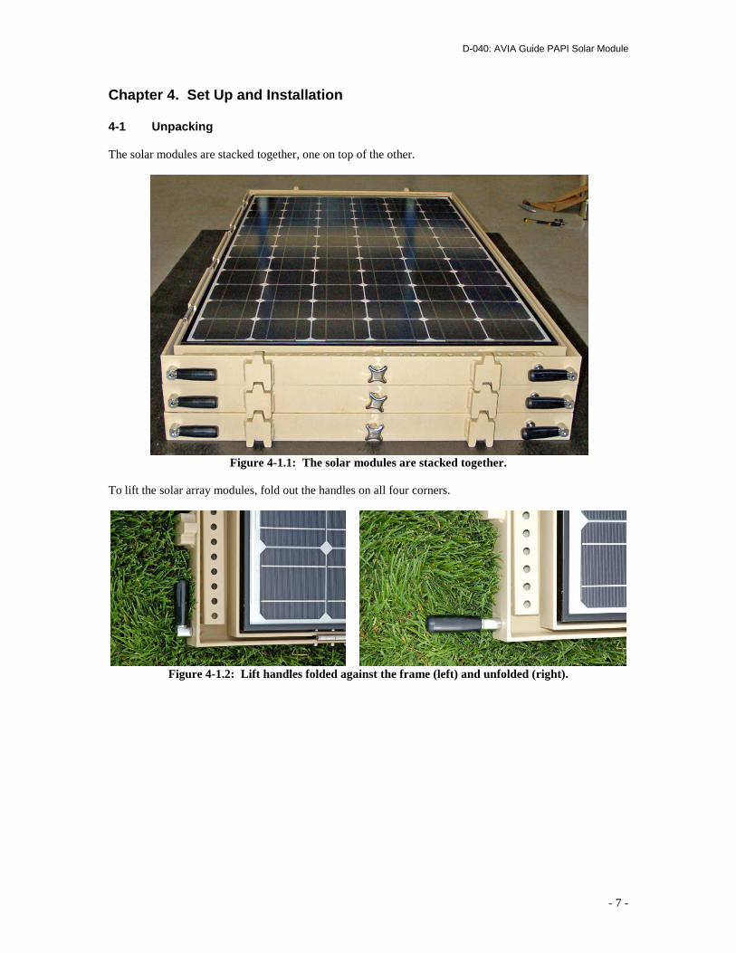
Chapter 4. Set Up and Installation 4-1 Unpacking The solar modules are stacked together, one on top of the other.
Figure 4-1.1: The solar modules are stacked together.
To lift the solar array modules, fold out the handles on all four corners.
Figure 4-1.2: Lift handles folded against the frame (left) and unfolded (right).
D-040: AVIA Guide PAPI Solar Module
- 8 -
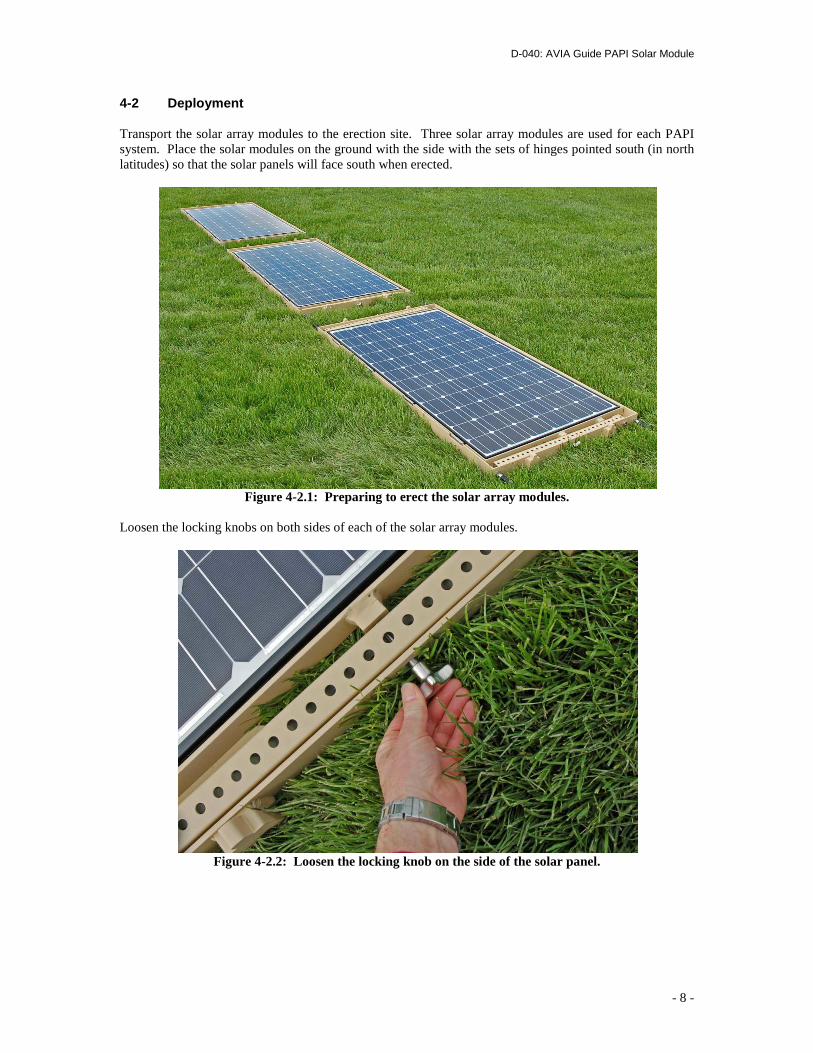
4-2 Deployment Transport the solar array modules to the erection site. Three solar array modules are used for each PAPI system. Place the solar modules on the ground with the side with the sets of hinges pointed south (in north latitudes) so that the solar panels will face south when erected.
Figure 4-2.1: Preparing to erect the solar array modules.
Loosen the locking knobs on both sides of each of the solar array modules.
Figure 4-2.2: Loosen the locking knob on the side of the solar panel.
D-040: AVIA Guide PAPI Solar Module
- 9 -
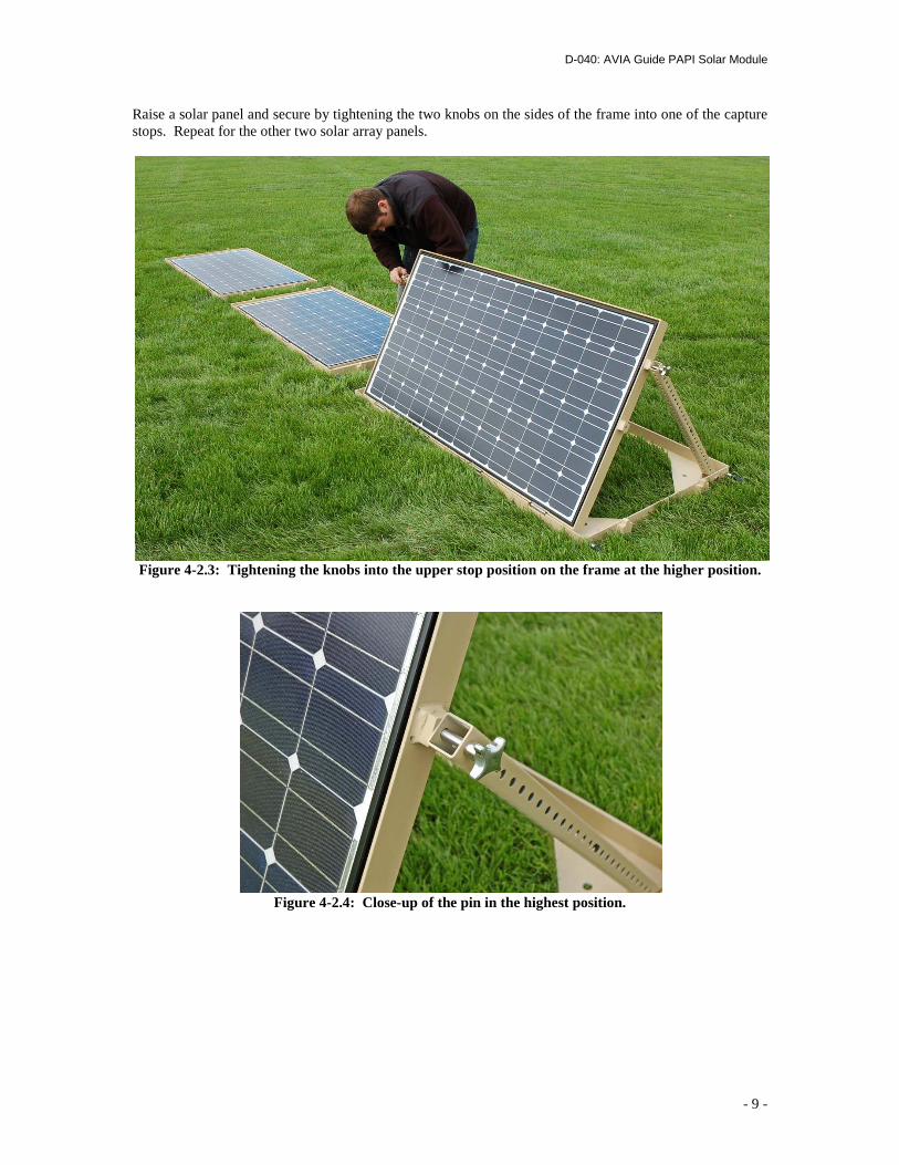
Raise a solar panel and secure by tightening the two knobs on the sides of the frame into one of the capture stops. Repeat for the other two solar array panels.
Figure 4-2.3: Tightening the knobs into the upper stop position on the frame at the higher position.
Figure 4-2.4: Close-up of the pin in the highest position.
D-040: AVIA Guide PAPI Solar Module
- 10 -
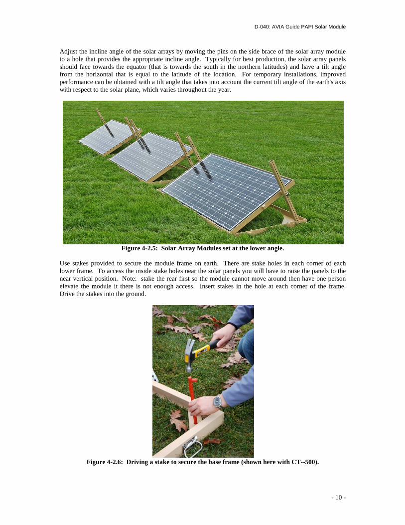
Adjust the incline angle of the solar arrays by moving the pins on the side brace of the solar array module to a hole that provides the appropriate incline angle. Typically for best production, the solar array panels should face towards the equator (that is towards the south in the northern latitudes) and have a tilt angle from the horizontal that is equal to the latitude of the location. For temporary installations, improved performance can be obtained with a tilt angle that takes into account the current tilt angle of the earth's axis with respect to the solar plane, which varies throughout the year.
Figure 4-2.5: Solar Array Modules set at the lower angle.
Use stakes provided to secure the module frame on earth. There are stake holes in each corner of each lower frame. To access the inside stake holes near the solar panels you will have to raise the panels to the near vertical position. Note: stake the rear first so the module cannot move around then have one person elevate the module it there is not enough access. Insert stakes in the hole at each corner of the frame. Drive the stakes into the ground.
Figure 4-2.6: Driving a stake to secure the base frame (shown here with CT--500).
D-040: AVIA Guide PAPI Solar Module
- 11 -
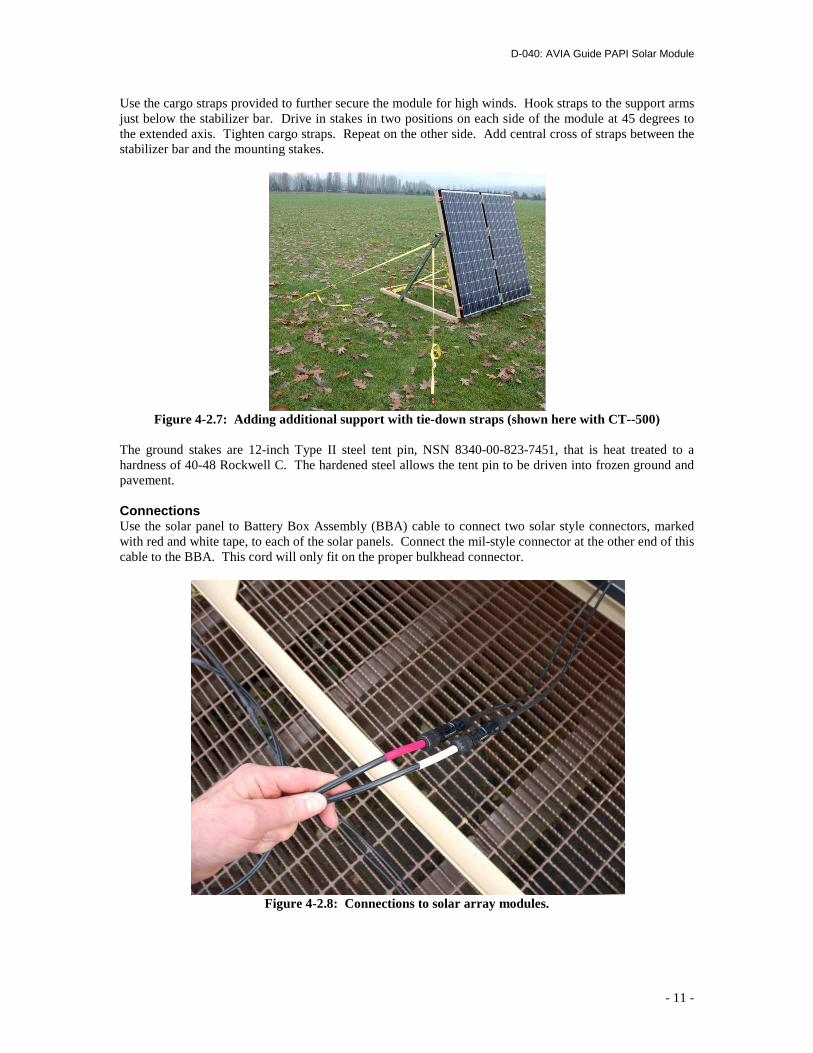
Use the cargo straps provided to further secure the module for high winds. Hook straps to the support arms just below the stabilizer bar. Drive in stakes in two positions on each side of the module at 45 degrees to the extended axis. Tighten cargo straps. Repeat on the other side. Add central cross of straps between the stabilizer bar and the mounting stakes.
Figure 4-2.7: Adding additional support with tie-down straps (shown here with CT--500)
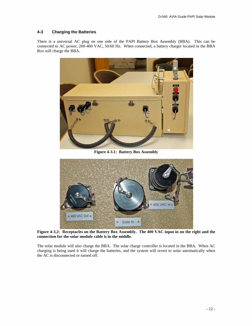
The ground stakes are 12-inch Type II steel tent pin, NSN 8340-00-823-7451, that is heat treated to a hardness of 40-48 Rockwell C. The hardened steel allows the tent pin to be driven into frozen ground and pavement. Connections Use the solar panel to Battery Box Assembly (BBA) cable to connect two solar style connectors, marked with red and white tape, to each of the solar panels. Connect the mil-style connector at the other end of this cable to the BBA. This cord will only fit on the proper bulkhead connector.
Figure 4-2.8: Connections to solar array modules.
D-040: AVIA Guide PAPI Solar Module
- 12 -
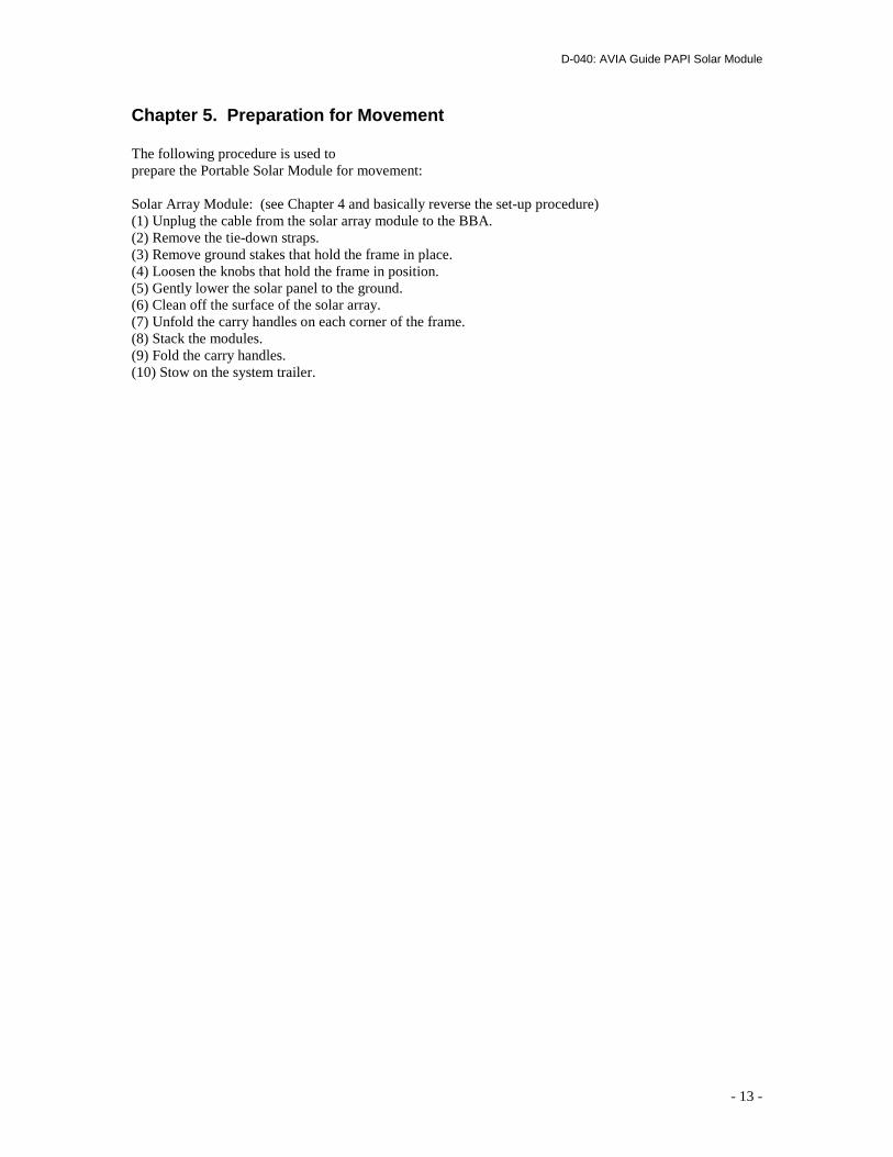
4-3 Charging the Batteries There is a universal AC plug on one side of the PAPI Battery Box Assembly (BBA). This can be connected to AC power, 200-400 VAC, 50/60 Hz. When connected, a battery charger located in the BBA Box will charge the BBA.
Figure 4-3.1: Battery Box Assembly
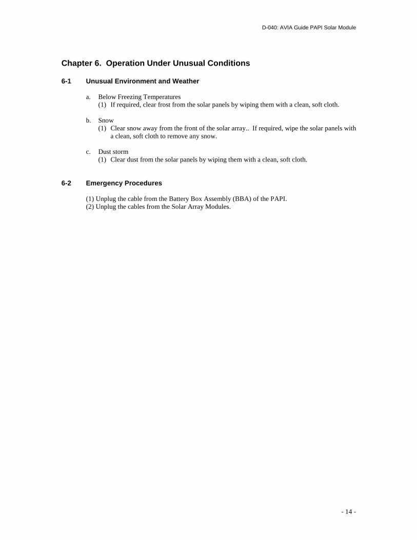
Figure 4-3.2: Receptacles on the Battery Box Assembly. The 400 VAC input in on the right and the connection for the solar module cable is in the middle. The solar module will also charge the BBA. The solar charge controller is located in the BBA. When AC charging is being used it will charge the batteries, and the system will revert to solar automatically when the AC is disconnected or turned off.
D-040: AVIA Guide PAPI Solar Module
- 13 -
Chapter 5. Preparation for Movement The following procedure is used to prepare the Portable Solar Module for movement: Solar Array Module: (see Chapter 4 and basically reverse the set-up procedure) (1) Unplug the cable from the solar array module to the BBA. (2) Remove the tie-down straps. (3) Remove ground stakes that hold the frame in place. (4) Loosen the knobs that hold the frame in position. (5) Gently lower the solar panel to the ground. (6) Clean off the surface of the solar array. (7) Unfold the carry handles on each corner of the frame. (8) Stack the modules. (9) Fold the carry handles. (10) Stow on the system trailer.
D-040: AVIA Guide PAPI Solar Module
- 14 -
Chapter 6. Operation Under Unusual Conditions 6-1 Unusual Environment and Weather a. Below Freezing Temperatures (1) If required, clear frost from the solar panels by wiping them with a clean, soft cloth. b. Snow (1) Clear snow away from the front of the solar array.. If required, wipe the solar panels with
a clean, soft cloth to remove any snow. c. Dust storm (1) Clear dust from the solar panels by wiping them with a clean, soft cloth. 6-2 Emergency Procedures
(1) Unplug the cable from the Battery Box Assembly (BBA) of the PAPI. (2) Unplug the cables from the Solar Array Modules.
D-040: AVIA Guide PAPI Solar Module
- 15 -
Chapter 7. Maintenance 7-1 Checks Before and After Deployment Move the Portable Solar Module to a work area. If the solar panels are dirty, rinse the panels by spraying with clean water and wiping off any debris with a soft cloth. Set up the solar module and (BBA) as explained in Chapter 4, except that they do not need to be set up next to the runway, and do not need to be secured. Inside the BBA are charge controllers. The charge controllers have a status light that will be green when running properly, i.e. charging the batteries. When there is an error, then the status light will be red or flashing red. If the status LED is off, but there is a brief flicker every 5 seconds, then there is not enough light illuminating the solar panels and the charge controller has switched to night mode. If a charge controller does not show a green status light, then remove the cable from the solar panels to the BBA. With the solar panels pointed toward the sun (or a suitable bright light source), check the voltage at the end of the cable from the solar panels. The voltage should be greater than 24 VDC and as high as 47 VDC. Reconnect the cable to the BBA. Check the voltages at the output receptacle of the BBA. It should be nominal 24 VDC. 7-2 Maintenance While Deployed During deployment the only required maintenance under normal operating conditions is a weekly cleaning of the solar panels by spraying with clean water and wiping off any debris with a soft cloth. The solar panels should also be cleaned after a storm. 7-3 Periodic Preventative Maintenance No periodic preventive maintenance is required. To maintain readiness, it is recommended that the procedures in Section 9-1 should be performed every three months.
D-040: AVIA Guide PAPI Solar Module
- 16 -
Chapter 8. Parts Replacement It is best if replacement of any part is performed in a clean, dry environment. However if necessary, part replacement can be performed while deployed. 8-1 Replacement of a solar panel Remove the connector at the rear of the solar array module. Remove four 1/4-20 button-head cap screws that hold the solar panel in the frame. Store the bolts in a clean, dry location. Note the orientation of the solar panel in the module frame. Remove the solar panel from the frame. Place the new solar panel into the frame in the same orientation as the old panel. Replace the four 1/4-20 bolts to hold the panel in the frame. Reconnect the connector at the rear of the solar array module. Parts Needed: Solar panel Tools needed: 5/32-inch hex wrench
D-040: AVIA Guide PAPI Solar Module
- 17 -
Chapter 9. Troubleshooting In the event that the Portable Solar Module is not functioning properly, the first action is to ensure that all of the cables are attached properly. See Chapter 4. Disconnect the cable from the PAPI Battery Box Assembly (BBA) at the BBA. Check the voltages at the output receptacle of the BBA. It should be a nominal 24 VDC, which can be between 22 and 28.8 VDC, depending upon the state of charge. If the voltage is zero, then open the top of the BBA box and check the circuit breaker, which is located on the side of the battery box. Reset the circuit breaker and make sure that its switch is in the on position. If the voltage is below 24 VDC, charge the batteries (See Chapter 4). Repeat the output voltage measurement. If the voltage remains below 22 VDC, replace the batteries. With the solar panels pointed toward the sun (or a suitable bright light source), check the voltage at the end of the cable from the solar panels. The voltage should be greater than 24 VDC, and as high as 47 VDC.
D-040: AVIA Guide PAPI Solar Module
- 18 -
APPENDIX A
Carmanah Technologies, Corp. Limited Warranty
One-Year Limited Hardware Warranty Carmanah Technologies, Corp. (Carmanah) warrants your portable airfield lighting product against defects in materials and workmanship for a period of one year from delivery. If Carmanah receives notice of such defects during the warranty period, Carmanah will either, at its option, repair or replace products that prove to be defective. Carmanah will make the final determination as to the cause or existence of the defect. Products that have been repaired or replaced by Carmanah under the initial warranty will be warranted only for the balance of the warranty period on the originally supplied product. Exclusions The above warranty shall not apply to defects or damage resulting from: improper or inadequate maintenance by customer; customer-supplied interfacing; unauthorized modification; misuse; operation outside of the environmental specifications for the product; or improper site preparation and maintenance. This warranty does not extend to damage caused by negligent or improper handling in use, storage, or transportation, nor to products from which the original identification markings or labels have been removed, defaced, or altered. Transferability This warranty is transferable from the original purchaser of this product to subsequent buyers, providing that proof of legal transfer is supplied to Carmanmah before any warranty service is requested. Carmanah reserves the right to verify such transfer with the original purchaser before warranty service is performed. Obtaining Warranty Service To obtain warranty service, products must be returned to a service facility designated by Carmanah. Customer shall prepay shipping charges for products returned to Carmanah for warranty service. Customer shall pay all shipping charges, duties, and taxes for products returned to Carmanah. Carmanah may repair on-site at the option of the customer. Customer is responsible for travel charges and personnel labor expenses when on-site repair is requested. Customer shall pay travel charges and personnel labor expenses when on-site repair is requested. Warranty Limitations EXCEPT AS SPECIFICALLY STATED HEREIN, THERE ARE NO OTHER EXPRESSED OR IMPLIED WARRANTIES. WITHOUT LIMITING THE GENERALITY OF THE FOREGOING, THERE ARE NO IMPLIED OR
D-040: AVIA Guide PAPI Solar Module
- 19 -
EXPRESSED WARRANTIES OF MERCHANTABILITY OR FITNESS FOR A PARTICULAR PURPOSE. Failure to Pay in Full If the equipment has not been paid in full, then the Warranty is voided. Carmanah will not be under any obligation to make any warranty repairs. Exclusive Remedies THE REMEDIES PROVIDED HEREIN ARE CUSTOMER'S SOLE AND EXCLUSIVE REMEDIES. IN NO EVENT SHALL CARMANAH BE LIABLE FOR ANY DIRECT, INDIRECT, SPECIAL, INCIDENTAL, OR CONSEQUENTIAL DAMAGES, WHETHER BASED ON CONTRACT, TORT, OR ANY OTHER LEGAL THEORY. Obtaining Service During Warranty Period If your product should fail during the warranty period, first follow the test procedures in the Operating Manual. Then contact CARMANAH by telephone at 877-722-8877 (North America) or +250-412-8331 or via email at [email protected] to obtain a Return Authorization Number and shipping instructions. Before requesting a Return Authorization Number, please be prepared to furnish the following information: product model number and serial number; date of shipment/purchase; brief description of problem; name, telephone number, and email address of the person at your organization for further communication. Bring or ship (freight and insurance prepaid) the failed piece of equipment to: Carmanah. Shipping damage as a result of inadequate packaging is the customer's responsibility. Customer has the option of requesting on-site repair, in which case customer shall pay all travel and personnel labor charges. Service after Warranty Period If your equipment should fail after the warranty period, follow the test procedures in the Operation Manual. Then contact Carmanah by telephone at 877.772.8877 (North America) or 250.415.3053 (Worldwide) or email at [email protected] for details of the services available. Carmanah will repair, or make fully functional if original parts are no longer available, any product which it has manufactured. Customer shall pay for these repairs.
D-040: AVIA Guide PAPI Solar Module
- 20 -
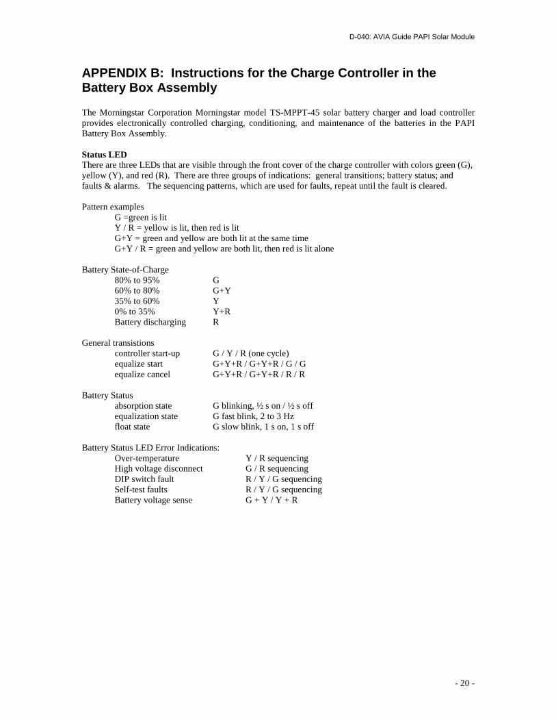
APPENDIX B: Instructions for the Charge Controller in the Battery Box Assembly The Morningstar Corporation Morningstar model TS-MPPT-45 solar battery charger and load controller provides electronically controlled charging, conditioning, and maintenance of the batteries in the PAPI Battery Box Assembly. Status LED There are three LEDs that are visible through the front cover of the charge controller with colors green (G), yellow (Y), and red (R). There are three groups of indications: general transitions; battery status; and faults & alarms. The sequencing patterns, which are used for faults, repeat until the fault is cleared. Pattern examples G =green is lit Y / R = yellow is lit, then red is lit G+Y = green and yellow are both lit at the same time G+Y / R = green and yellow are both lit, then red is lit alone Battery State-of-Charge 80% to 95% G 60% to 80% G+Y 35% to 60% Y 0% to 35% Y+R Battery discharging R General transistions controller start-up G / Y / R (one cycle) equalize start G+Y+R / G+Y+R / G / G equalize cancel G+Y+R / G+Y+R / R / R Battery Status absorption state G blinking, ½ s on / ½ s off equalization state G fast blink, 2 to 3 Hz float state G slow blink, 1 s on, 1 s off Battery Status LED Error Indications: Over-temperature Y / R sequencing High voltage disconnect G / R sequencing DIP switch fault R / Y / G sequencing Self-test faults R / Y / G sequencing Battery voltage sense G + Y / Y + R
D-040: AVIA Guide PAPI Solar Module
- 21 -
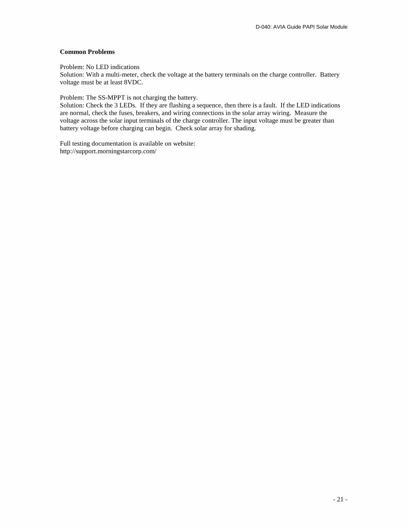
Common Problems Problem: No LED indications Solution: With a multi-meter, check the voltage at the battery terminals on the charge controller. Battery voltage must be at least 8VDC. Problem: The SS-MPPT is not charging the battery. Solution: Check the 3 LEDs. If they are flashing a sequence, then there is a fault. If the LED indications are normal, check the fuses, breakers, and wiring connections in the solar array wiring. Measure the voltage across the solar input terminals of the charge controller. The input voltage must be greater than battery voltage before charging can begin. Check solar array for shading. Full testing documentation is available on website: http://support.morningstarcorp.com/