7.ECE 301 - Behavioral Modeling I
18
VIT U N I V E R S I T Y ECE 301 - VLSI Syste m Desi gn (Fall 2011) Verilog HDL - Prof.S.Sivanantham VIT University V ellore , T amilna du. India E-mail: [email protected]
Transcript of 7.ECE 301 - Behavioral Modeling I
7/27/2019 7.ECE 301 - Behavioral Modeling I
http://slidepdf.com/reader/full/7ece-301-behavioral-modeling-i 1/18
VITU N I V E R S I T Y
ECE 301 - VLSI System Design(Fall 2011)
Verilog HDL -
Prof.S.Sivanantham
VIT University
Vellore, Tamilnadu. India
E-mail: [email protected]
7/27/2019 7.ECE 301 - Behavioral Modeling I
http://slidepdf.com/reader/full/7ece-301-behavioral-modeling-i 2/18
After completing this chapter, you will be able to:
Describe the behavioral modeling structures
Describe procedural constructs
n ers an e ea ures o n a oc s
Understand the features of always blocks
nonblocking assignments
ECE301 VLSI System Design FALL 2011 S.Sivanantham
7/27/2019 7.ECE 301 - Behavioral Modeling I
http://slidepdf.com/reader/full/7ece-301-behavioral-modeling-i 3/18
Assignments:
blocking assignment (=) nonblocking assignment (<=)
ass gn … eass gn
force … release
Selection structures: … e se
case (case, casex, casez)
Iterative structures:
repeat for
while
ECE301 VLSI System Design FALL 2011 S.Sivanantham
forever
7/27/2019 7.ECE 301 - Behavioral Modeling I
http://slidepdf.com/reader/full/7ece-301-behavioral-modeling-i 4/18
7/27/2019 7.ECE 301 - Behavioral Modeling I
http://slidepdf.com/reader/full/7ece-301-behavioral-modeling-i 5/18
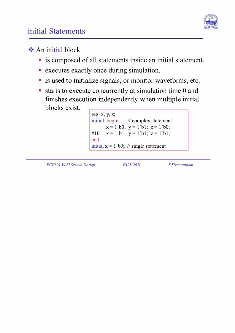
An initial block
is composed of all statements inside an initial statement. executes exactly once during simulation.
s use o n a ze s gna s, or mon or wave orms, e c.
starts to execute concurrently at simulation time 0 and
finishes execution inde endentl when multi le initial
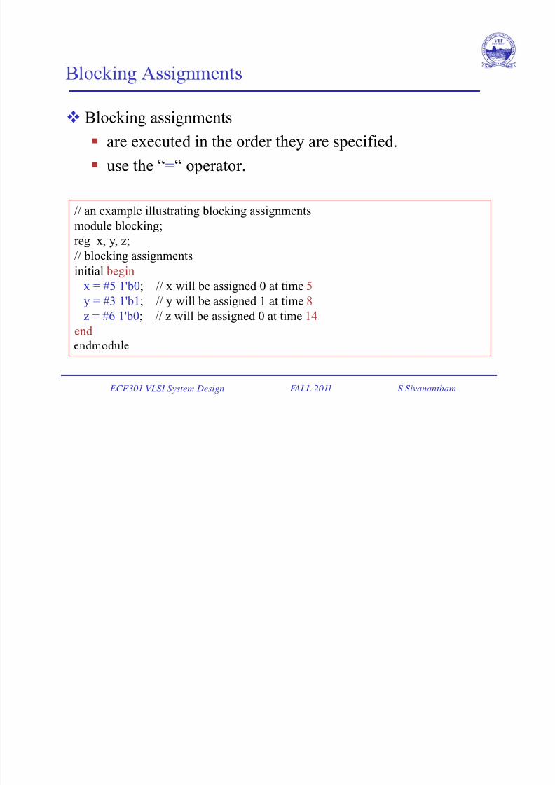
blocks exist.reg x, y, z;
initial begin // complex statement
x = 1`b0; y = 1`b1; z = 1`b0;#10 x = 1`b1; y = 1`b1; z = 1`b1;
end
= `
ECE301 VLSI System Design FALL 2011 S.Sivanantham
7/27/2019 7.ECE 301 - Behavioral Modeling I
http://slidepdf.com/reader/full/7ece-301-behavioral-modeling-i 6/18
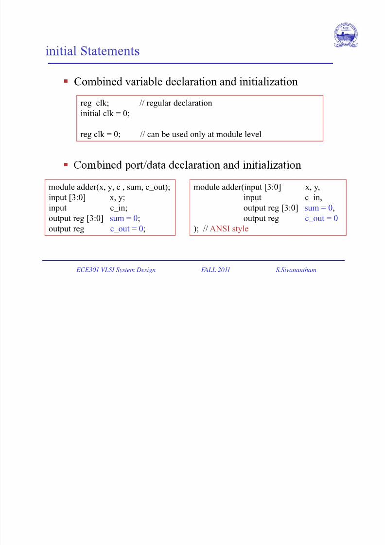
Combined variable declaration and initialization
reg clk; // regular declarationinitial clk = 0;
reg clk = 0; // can be used only at module level
module adder(x, y, c , sum, c_out);
input [3:0] x, y;
module adder(input [3:0] x, y,
input c_in,
input c_in;output reg [3:0] sum = 0;
output reg c_out = 0;
output reg [3:0] sum = 0,output reg c_out = 0
); // ANSI style
ECE301 VLSI System Design FALL 2011 S.Sivanantham
7/27/2019 7.ECE 301 - Behavioral Modeling I
http://slidepdf.com/reader/full/7ece-301-behavioral-modeling-i 7/18
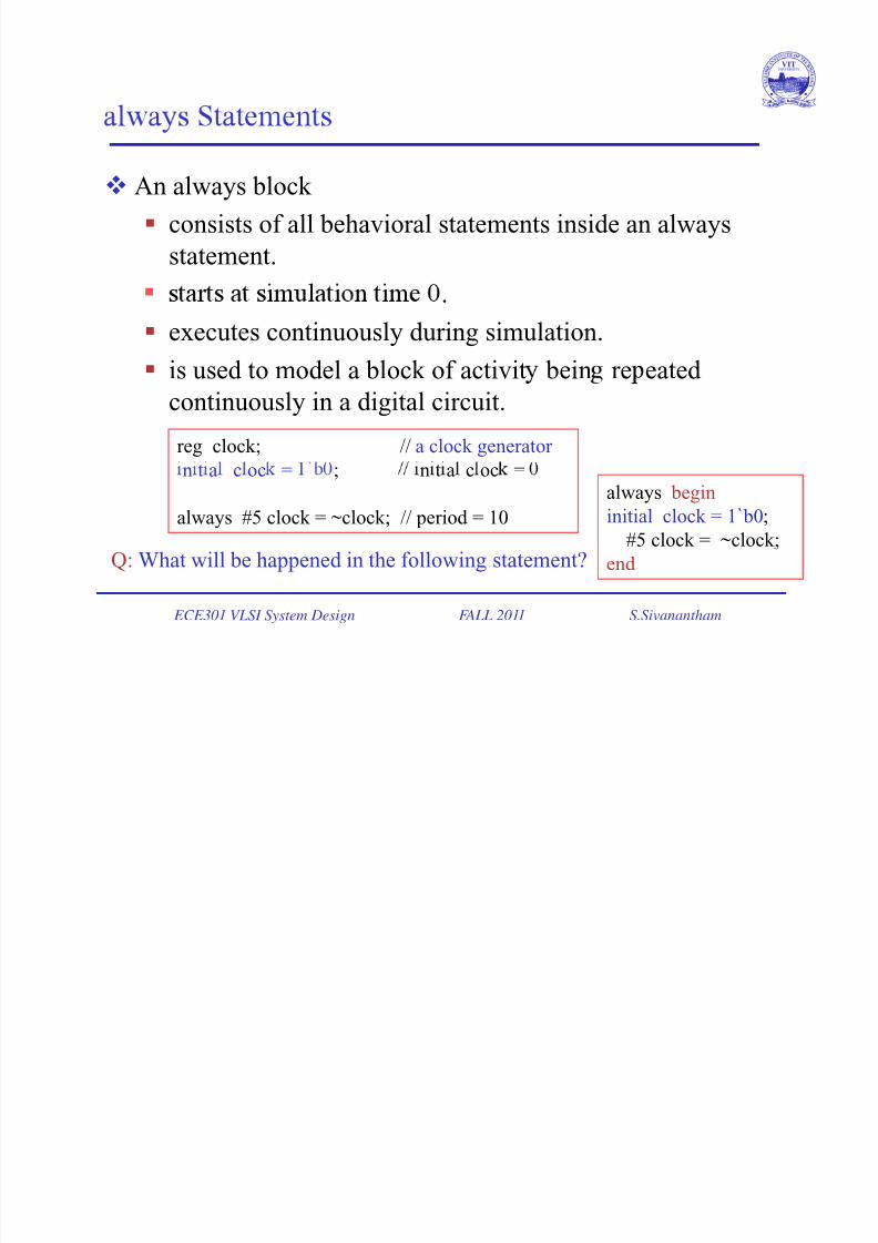
An always block
consists of all behavioral statements inside an alwaysstatement.
.
executes continuously during simulation.
is used to model a block of activit bein re eated
continuously in a digital circuit.
reg clock; // a clock generator
`n t a c oc = ; n t a c oc =
always #5 clock = ~clock; // period = 10
always begin
initial clock = 1`b0;
#5 clock = ~clock;
ECE301 VLSI System Design FALL 2011 S.Sivanantham
Q: What will be happened in the following statement? end
7/27/2019 7.ECE 301 - Behavioral Modeling I
http://slidepdf.com/reader/full/7ece-301-behavioral-modeling-i 8/18
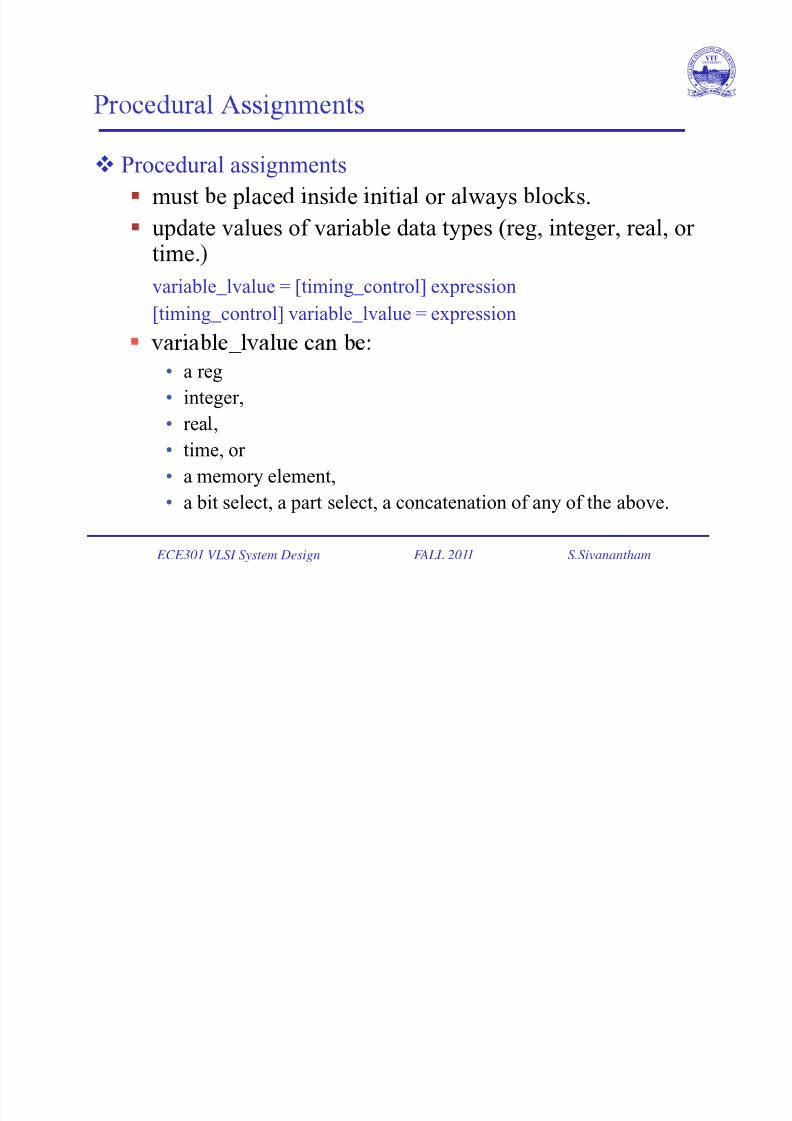
Procedural assignments
must e p ace ns e n t a or a ways oc s.
update values of variable data types (reg, integer, real, or time.
variable_lvalue = [timing_control] expression
[timing_control] variable_lvalue = expression _
• a reg
• integer,
• rea ,• time, or
• a memory element,
ECE301 VLSI System Design FALL 2011 S.Sivanantham
• a bit select, a part select, a concatenation of any of the above.
7/27/2019 7.ECE 301 - Behavioral Modeling I
http://slidepdf.com/reader/full/7ece-301-behavioral-modeling-i 9/18
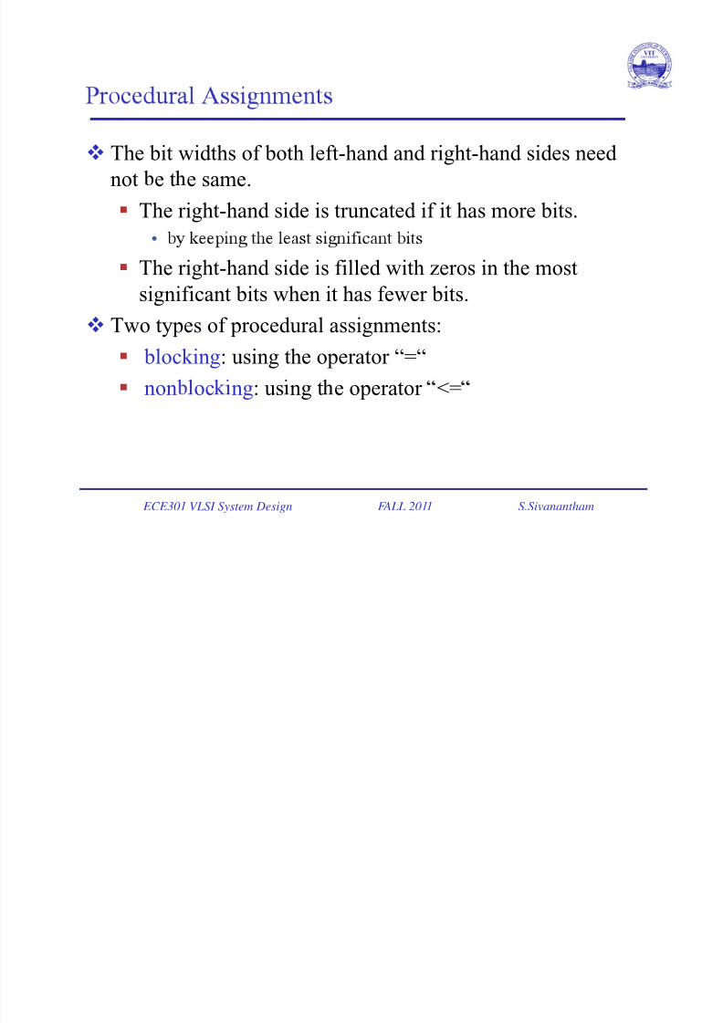
The bit widths of both left-hand and right-hand sides need
not e t e same.
The right-hand side is truncated if it has more bits.
•
The right-hand side is filled with zeros in the most
significant bits when it has fewer bits. Two types of procedural assignments:
blocking: using the operator “=“
non oc ng: us ng t e operator <=
ECE301 VLSI System Design FALL 2011 S.Sivanantham
7/27/2019 7.ECE 301 - Behavioral Modeling I
http://slidepdf.com/reader/full/7ece-301-behavioral-modeling-i 10/18
7/27/2019 7.ECE 301 - Behavioral Modeling I
http://slidepdf.com/reader/full/7ece-301-behavioral-modeling-i 11/18
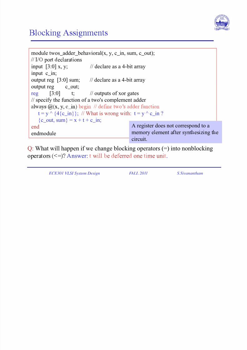
module twos_adder_behavioral(x, y, c_in, sum, c_out);
por ec ara ons
input [3:0] x, y; // declare as a 4-bit arrayinput c_in;
output reg [3:0] sum; // declare as a 4-bit array
output reg c_out;
reg [3:0] t; // outputs of xor gates
// specify the function of a two's complement adder ’, , _
t = y ^ {4{c_in}}; // What is wrong with: t = y ^ c_in ?
{c_out, sum} = x + t + c_in;
end A register does not correspond to a
endmodule memory e ement a ter synt es z ng t ecircuit.
Q: What will happen if we change blocking operators (=) into nonblocking
ECE301 VLSI System Design FALL 2011 S.Sivanantham
opera ors = nswer: w e e erre one me un .
7/27/2019 7.ECE 301 - Behavioral Modeling I
http://slidepdf.com/reader/full/7ece-301-behavioral-modeling-i 12/18
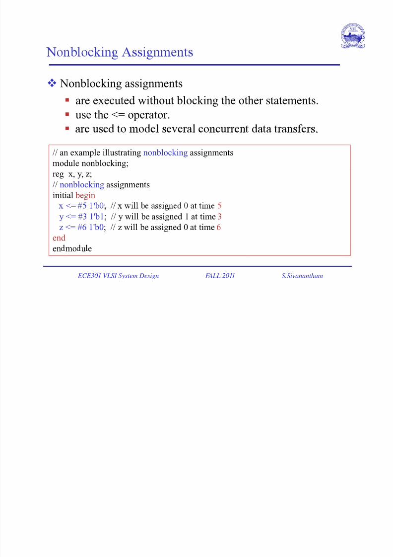
Nonblocking assignments
are executed without blocking the other statements.
use the <= operator.
.
// an example illustrating nonblocking assignments
module nonblocking;reg x, y, z;
// nonblocking assignments
initial begin
<= '
y <= #3 1'b1; // y will be assigned 1 at time 3z <= #6 1'b0; // z will be assigned 0 at time 6
end
ECE301 VLSI System Design FALL 2011 S.Sivanantham
en mo u e
7/27/2019 7.ECE 301 - Behavioral Modeling I
http://slidepdf.com/reader/full/7ece-301-behavioral-modeling-i 13/18
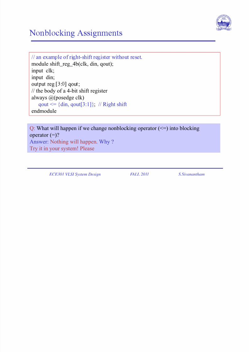
// an exam le of ri ht-shift re ister without reset.
module shift_reg_4b(clk, din, qout);
input clk;
input din;
ou pu reg : qou ;
// the body of a 4-bit shift register
always @(posedge clk)
qout <= {din, qout[3:1]}; // Right shift
endmodule
Q: What will happen if we change nonblocking operator (<=) into blocking
operator (=)?Answer: Nothing will happen. Why ?
Try it in your system! Please
ECE301 VLSI System Design FALL 2011 S.Sivanantham
7/27/2019 7.ECE 301 - Behavioral Modeling I
http://slidepdf.com/reader/full/7ece-301-behavioral-modeling-i 14/18
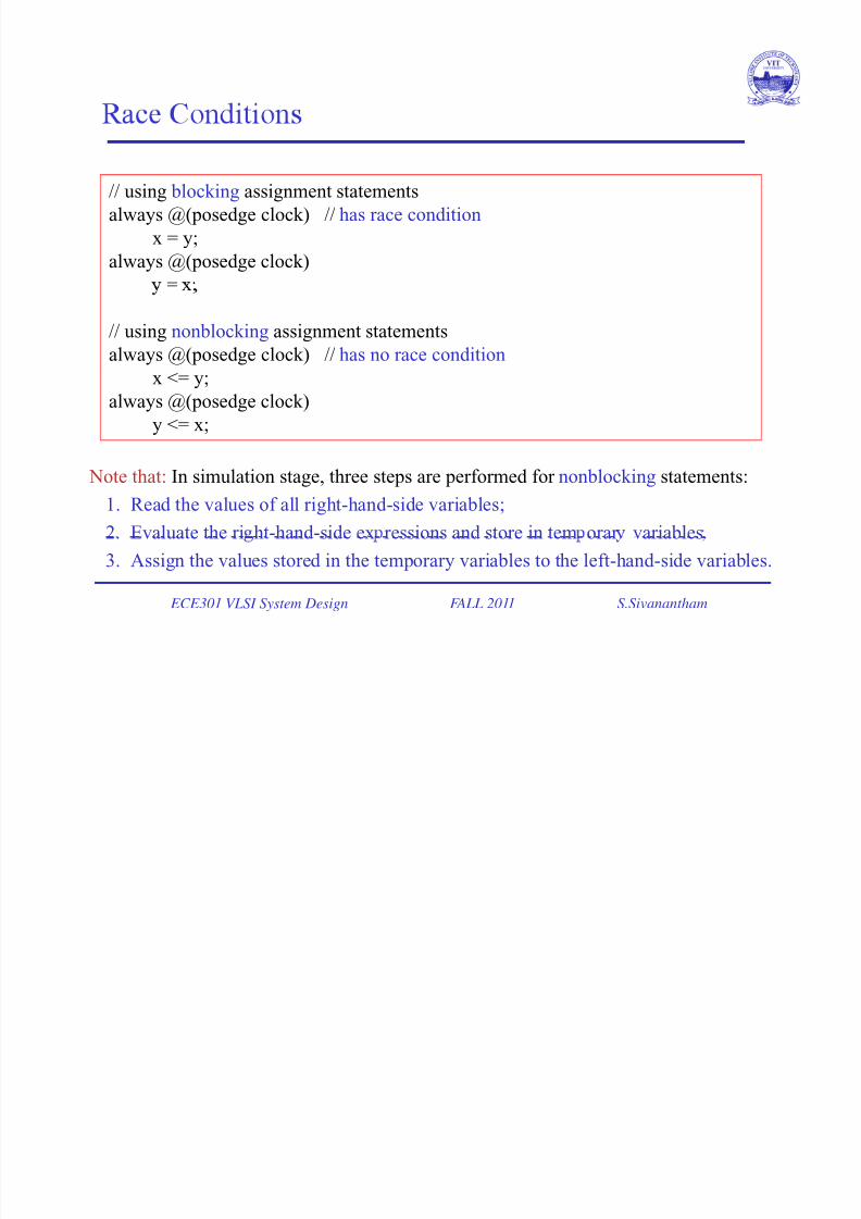
// using blocking assignment statements
always @(posedge clock) // has race condition
x = y;always @(posedge clock)
=
// using nonblocking assignment statements
always @(posedge clock) // has no race conditionx <= y;
always @(posedge clock)
y <= x;
Note that: In simulation stage, three steps are performed for nonblocking statements:
1. Read the values of all right-hand-side variables;
2. Evaluate the ri ht-hand-side ex ressions and store in tem orar variables
ECE301 VLSI System Design FALL 2011 S.Sivanantham
3. Assign the values stored in the temporary variables to the left-hand-side variables.
7/27/2019 7.ECE 301 - Behavioral Modeling I
http://slidepdf.com/reader/full/7ece-301-behavioral-modeling-i 15/18
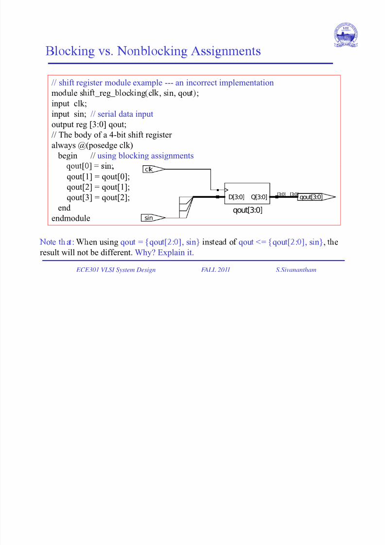
// shift register module example --- an incorrect implementation
mo u e s _reg_ oc ng c , s n, qou ;
input clk;input sin; // serial data input
output reg [3:0] qout;
// The body of a 4-bit shift register
always @(posedge clk)
begin // using blocking assignments
qout[1] = qout[0];
qout[2] = qout[1];
qout[3] = qout[2]; qout[3:0][3:0]
clk
[3:0]Q[3:0]D[3:0]
end endmodule
qout[3:0]sin
ECE301 VLSI System Design FALL 2011 S.Sivanantham
o e a : en us ng qou = qou : , s n ns ea o qou = qou : , s n , e
result will not be different. Why? Explain it.
7/27/2019 7.ECE 301 - Behavioral Modeling I
http://slidepdf.com/reader/full/7ece-301-behavioral-modeling-i 16/18
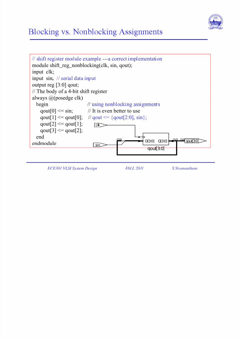
s t reg ster mo u e examp e ---a correct mp ementat on
module shift_reg_nonblocking(clk, sin, qout);input clk;
in ut sin // serial data in ut
output reg [3:0] qout;
// The body of a 4-bit shift register
always @(posedge clk)eg n us ng non oc ng ass gnmen s
qout[0] <= sin; // It is even better to use
qout[1] <= qout[0]; // qout <= {qout[2:0], sin};
qout[2] <= qout[1]; cl
qout[3] <= qout[2];end
endmoduleout3:0
qout[3:0][3:0]
sin
[2:0] [3:0]Q[3:0]D[3:0]
ECE301 VLSI System Design FALL 2011 S.Sivanantham
7/27/2019 7.ECE 301 - Behavioral Modeling I
http://slidepdf.com/reader/full/7ece-301-behavioral-modeling-i 17/18
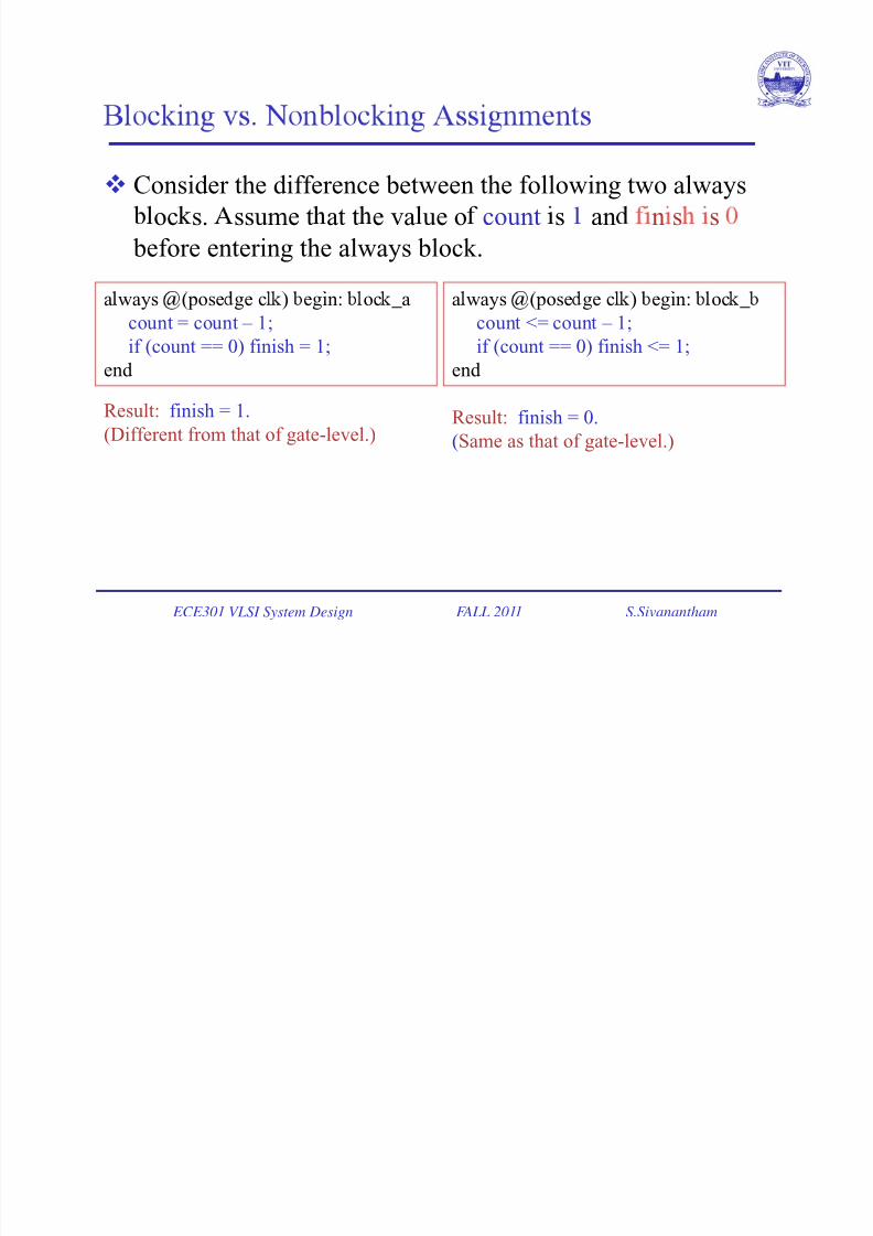
Consider the difference between the following two always
oc s. ssume t at t e va ue o count s an n s s
before entering the always block.
a ways (pose ge c ) egin: oc _a
count = count – 1;
if (count == 0) finish = 1;
end
a ways (pose ge c ) egin: oc _
count <= count – 1;
if (count == 0) finish <= 1;
end
Result: finish = 1.
(Different from that of gate-level.)Result: finish = 0.
(Same as that of gate-level.)
ECE301 VLSI System Design FALL 2011 S.Sivanantham
7/27/2019 7.ECE 301 - Behavioral Modeling I
http://slidepdf.com/reader/full/7ece-301-behavioral-modeling-i 18/18
Coding style: In the always block
Use nonblocking operators (<=) when it is a piece of
sequential logic;
• ,
that of gate-level.
Use blocking operators (=) when it is a piece of com na ona og c.
ECE301 VLSI System Design FALL 2011 S.Sivanantham