Digital Design - Combinational Logic Design Chapter 2 - Combinational Logic Design.
date post
19-Dec-2015Category
view
215download
2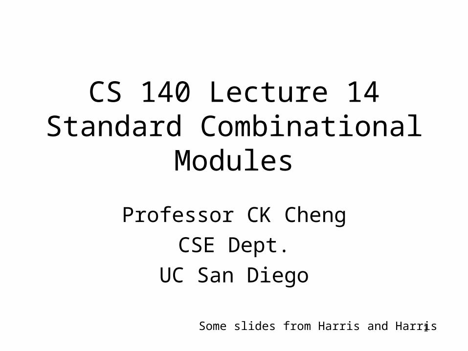
1
CS 140 Lecture 14Standard Combinational Modules
Professor CK Cheng
CSE Dept.
UC San Diego
Some slides from Harris and Harris

2
Part III. Standard Modules
A. InterconnectB. Operators. Adders Multiplier
Adders 1. Representation of numbers2. Full Adder3. Half Adder4. Ripple-Carry Adder
5. Carry Look Ahead Adder 6. Prefix AdderALUMultiplierDivision
Operators
• Specification: Data Representations
• Arithmetic: Algorithms
• Logic: Synthesis
• Layout: Placement and Routing
3

4
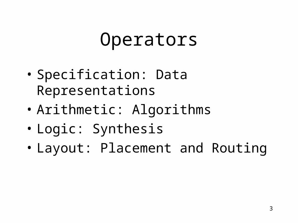
1. Representation
• 2’s Complement
-x: 2n-x
• 1’s Complement
-x: 2n-x-1
5
1. RepresentationId 2’s
comp.1’s comp.
0 0 15
-1 15 14
-2 14 13
-3 13 12
-4 12 11
-5 11 10
-6 10 9
-7 9 8
-8 8
• 2’s Complement
-x: 2n-x
e.g. 16-x
• 1’s Complement
-x: 2n-x-1
e.g. 16-x-1

6
1. Representation
Id -Binary sign mag 2’s comp 1’s comp
0 0000 1000 0000 1111
-1 0001 1001 1111 1110
-2 0010 1010 1110 1101
-3 0011 1011 1101 1100
-4 0100 1100 1100 1011
-5 0101 1101 1011 1010
-6 0110 1110 1010 1001
-7 0111 1111 1001 1000
-8 1000

7
Representation
1’s Complement
For a negative number, we take the positive number and complement every bit.
2’s Complement
For a negative number, we do 1s complement and plus one.
(bn-1, bn-2, …, b0): -bn-12n-1+ sumi<n-1 bi2i

8
Representation
2’s Complement
• x+y
• x-y: x+2n-y= 2n+x-y
• -x+y: 2n-x+y
• -x-y: 2n-x+2n-y
= 2n+2n-x-y
• -(-x)=2n-(2n-x)=x
1’s Complement
• x+y
• x-y: x+2n-y-1= 2n-1+x-y
• -x+y: 2n-x-1+y=2n-1-x+y
• -x-y: 2n-x-1+2n-y-1
= 2n-1+2n-x-y-1
• -(-x)=2n-(2n-x-1) -1=x

9
2 + 3 = 50 0 1 0 0 0 1 0+ 0 0 1 1 0 1 0 1
2 - 3 = -1 (2’s)0 0 0 0 0 0 1 0+ 1 1 0 1 1 1 1 1
2 - 3 = -1 (1’s)
0 0 1 0+ 1 1 0 0 1 1 1 0
Examples
-2 - 3 = -5 (2’s)1 1 0 0 1 1 1 0+ 1 1 0 1 1 0 1 1
-2 - 3 = -5 (1’s)1 1 0 0 1 1 0 1+ 1 1 0 0 1 0 0 1 1 1 0 1 0
3 + 5 = 80 1 1 1 0 0 1 1+ 0 1 0 1 1 0 0 0C4C3
Check for overflow (2’s)
-3 + -5 = -81 1 1 1 1 1 0 1+ 1 0 1 1 1 0 0 0C4C3

10
Addition: 2’s Complement Overflow
In 2’s complement: overflow = cn xor cn-1
Exercise:1.Demonstrate the overflow with more examples.2.Prove the condition.

11
Adder
MUX
Sum
minus
b b’a
Cout
overflowC4
C3
Cin
Addition and Subtraction using 2’s Complement

12
1-Bit Adders
A B
0 00 11 01 1
0110
SCout
0001
S = A BCout = AB
HalfAdder
A B
S
Cout +
A B
0 00 11 01 1
0110
SCout
0001
S = A B CinCout = AB + ACin + BCin
FullAdder
Cin
0 00 11 01 1
00001111
1001
0111
A B
S
Cout Cin+

13
a b Cout Sum
0 0 0 0
0 1 0 1
1 0 0 1
1 1 1 0
Sum = ab’ + a’b = a + b
Cout = ab
Cout
Sum
ab
HA
a b
SumCout
Half Adder

14
Full Adder Composed of Half Adders
HA
HA
a
b
cin
x
sum
cout OR
sum
cout
cout
sum
yz

15
Full Adder Composed of Half Adders
HA
HA
ab
cin
xsumcout
sum
cout
cout
sum
y z
Id a b cin x y z cout sum
0 0 0 0 0 0 0 0 0
1 0 0 1 0 0 0 0 1
2 0 1 0 0 1 0 0 1
3 0 1 1 0 1 1 1 0
4 1 0 0 0 1 0 0 1
5 1 0 1 0 1 1 1 0
6 1 1 0 1 0 0 1 0
7 1 1 1 1 0 0 1 1
Id x z cout
0 0 0 0
1 0 1 1
2 1 0 1
3 1 1 -

16
Adder
A B
S
Cout Cin+N
NN
• Several types of carry propagate adders (CPAs) are:– Ripple-carry adders (slow)
– Carry-lookahead adders (fast)
– Prefix adders (faster)
• Carry-lookahead and prefix adders are faster for large adders but require more hardware.
Symbol

17
• Chain 1-bit adders together• Carry ripples through entire chain• Disadvantage: slow
Ripple-Carry Adder
S31
A30 B30
S30
A1 B1
S1
A0 B0
S0
C31 C30 C2 C1Cout ++++
A31 B31
Cin

18
• The delay of an N-bit ripple-carry adder is:
tripple = NtFA
where tFA is the delay of a full adder
Ripple-Carry Adder Delay

19
• Compress the logic levels of Cout
• Some definitions:– Generate (Gi) and propagate (Pi) signals for each column:
• A column will generate a carry out if Ai AND Bi are both 1.
Gi = Ai Bi
• A column will propagate a carry in to the carry out if Ai OR Bi is 1.
Pi = Ai + Bi
• The carry out of a column (Ci) is:
Ci+1 = Ai Bi + (Ai + Bi )Ci = Gi + Pi Ci
Carry-Lookahead Adder
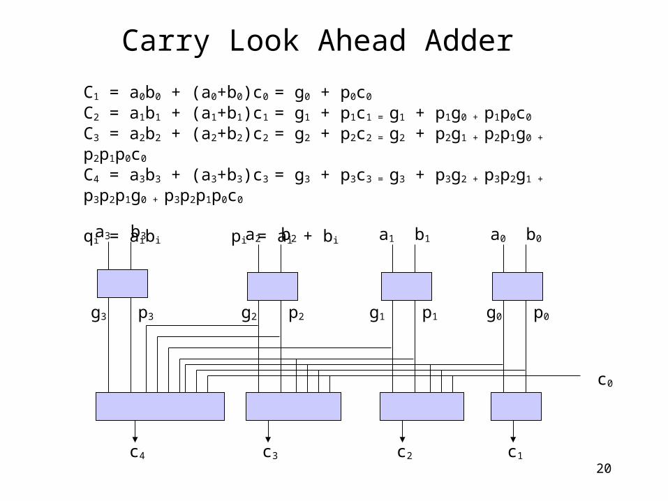
20
Carry Look Ahead Adder
C1 = a0b0 + (a0+b0)c0 = g0 + p0c0
C2 = a1b1 + (a1+b1)c1 = g1 + p1c1 = g1 + p1g0 + p1p0c0
C3 = a2b2 + (a2+b2)c2 = g2 + p2c2 = g2 + p2g1 + p2p1g0 + p2p1p0c0
C4 = a3b3 + (a3+b3)c3 = g3 + p3c3 = g3 + p3g2 + p3p2g1 + p3p2p1g0 + p3p2p1p0c0
qi = aibi pi = ai + bi
a3 b3
g3 p3
a2 b2
g2 p2
a1 b1
g1 p1
a0 b0
g0 p0
c1c2c3c4
c0
21
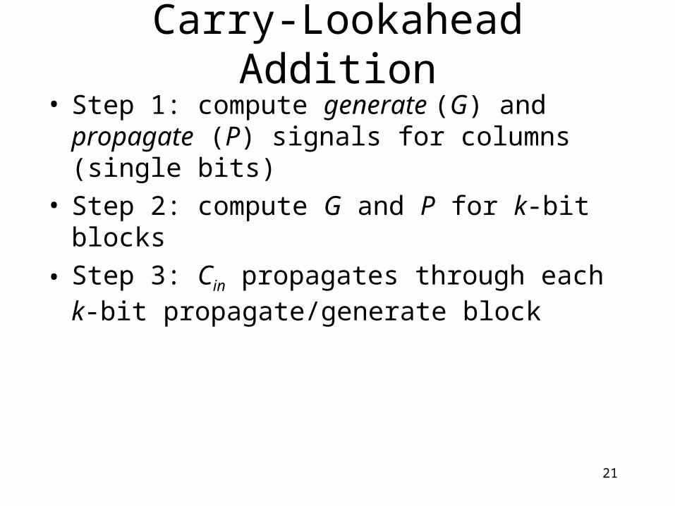
• Step 1: compute generate (G) and propagate (P) signals for columns (single bits)
• Step 2: compute G and P for k-bit blocks
• Step 3: Cin propagates through each k-bit propagate/generate block
Carry-Lookahead Addition

22
32-bit CLA with 4-bit blocks
B0
++++
P3:0
G3
P3
G2
P2
G1
P1
G0
P3
P2
P1
P0
G3:0
Cin
Cout
A0
S0
C1
B1 A1
S1
C2
B2 A2
S2
C3
B3 A3
S3
Cin
A3:0B3:0
S3:0
4-bit CLA Block
Cin
A7:4B7:4
S7:4
4-bit CLA Block
C4C8
A27:24B27:24
S27:24
4-bit CLA Block
C24
A31:28B31:28
S31:28
4-bit CLA Block
C28Cout
23
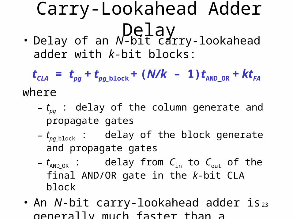
• Delay of an N-bit carry-lookahead adder with k-bit blocks:
tCLA = tpg + tpg_block + (N/k – 1)tAND_OR + ktFA
where– tpg : delay of the column generate and propagate gates
– tpg_block :delay of the block generate and propagate gates
– tAND_OR : delay from Cin to Cout of the final AND/OR gate in the k-bit CLA block
• An N-bit carry-lookahead adder is generally much faster than a ripple-carry adder for N > 16
Carry-Lookahead Adder Delay

24
Prefix Adder• Computes the carry in (Ci-1) for each of the columns
as fast as possible and then computes the sum:
Si = (Ai Bi) Ci
• Computes G and P for 1-bit, then 2-bit blocks, then 4-bit blocks, then 8-bit blocks, etc. until the carry in (generate signal) is known for each column
• Has log2N stages

25
Prefix Adder• A carry in is produced by being either generated in a
column or propagated from a previous column.
• Define column -1 to hold Cin, so G-1 = Cin, P-1 = 0
• Then, the carry in to col. i = the carry out of col. i-1: Ci-1 = Gi-1:-1
Gi-1:-1 is the generate signal spanning columns i-1 to -1.
There will be a carry out of column i-1 (Ci-1) if the block spanning columns i-1 through -1 generates a carry.
• Thus, we rewrite the sum equation:Si = (Ai Bi) Gi-1:-1
• Goal: Compute G0:-1, G1:-1, G2:-1, G3:-1, G4:-1, G5:-1, … (These are called the prefixes)

26
Prefix Adder• The generate and propagate signals for a block
spanning bits i:j are:
Gi:j = Gi:k Pi:k Gk-1:j
Pi:j = Pi:kPk-1:j
• In words, these prefixes describe that:– A block will generate a carry if the upper part (i:k)
generates a carry or if the upper part propagates a carry generated in the lower part (k-1:j)
– A block will propagate a carry if both the upper and lower parts propagate the carry.

27
Prefix Adder Schematic
0:-1
-1
2:1
1:-12:-1
012
4:3
3
6:5
5:36:3
456
5:-16:-1 3:-14:-1
8:7
7
10:9
9:710:7
8910
12:11
11
14:13
13:1114:11
121314
13:714:7 11:712:7
9:-110:-1 7:-18:-113:-114:-1 11:-112:-1
15
0123456789101112131415
BiAi
Gi:iPi:i
Gk-1:jPk-1:jGi:kPi:k
Gi:jPi:j
ii:j
BiAiGi-1:-1
Si
iLegend

28
• The delay of an N-bit prefix adder is:
tPA = tpg + log2N(tpg_prefix ) + tXOR
where– tpg is the delay of the column generate and propagate gates
(AND or OR gate)
– tpg_prefix is the delay of the black prefix cell (AND-OR gate)
Prefix Adder Delay

29
• Compare the delay of 32-bit ripple-carry, carry-lookahead, and prefix adders. The carry-lookahead adder has 4-bit blocks. Assume that each two-input gate delay is 100 ps and the full adder delay is 300 ps.
Adder Delay Comparisons

30
• Compare the delay of 32-bit ripple-carry, carry-lookahead, and prefix adders. The carry-lookahead adder has 4-bit blocks. Assume that each two-input gate delay is 100 ps and the full adder delay is 300 ps. tripple = NtFA = 32(300 ps) = 9.6 ns
tCLA = tpg + tpg_block + (N/k – 1)tAND_OR + ktFA
= [100 + 600 + (7)200 + 4(300)] ps
= 3.3 ns
tPA = tpg + log2N(tpg_prefix ) + tXOR
= [100 + log232(200) + 100] ps
= 1.2 ns
Adder Delay Comparisons
31
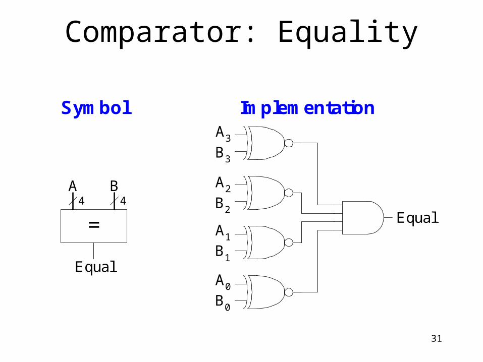
Comparator: Equality
Symbol ImplementationA3
B3
A2
B2
A1
B1
A0
B0
Equal=
A B
Equal
44

32
Comparator: Less Than
A < B
-
BA
[N-1]
N
N N
• For unsigned numbers

33
Arithmetic Logic Unit (ALU)
ALU
N N
N
3
A B
Y
F
F2:0 Function
000 A & B
001 A | B
010 A + B
011 not used
100 A & ~B
101 A | ~B
110 A - B
111 SLT
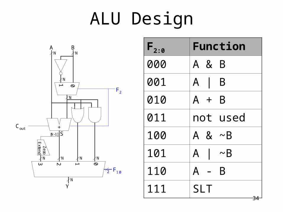
34
ALU Design
+
2 01
A B
Cout
Y
3
01
F2
F1:0
[N-1] S
NN
N
N
N NNN
N
2
Ze
roE
xtend
F2:0 Function
000 A & B
001 A | B
010 A + B
011 not used
100 A & ~B
101 A | ~B
110 A - B
111 SLT

35
Set Less Than (SLT) Example
+
2 01
A B
Cout
Y
3
01
F2
F1:0
[N-1] S
NN
N
N
N NNN
N
2
Ze
roE
xtend
• Configure a 32-bit ALU for the set if less than (SLT) operation. Suppose A = 25 and B = 32.

36
Set Less Than (SLT) Example
+
2 01
A B
Cout
Y
3
01
F2
F1:0
[N-1] S
NN
N
N
N NNN
N
2
Ze
roE
xtend
• Configure a 32-bit ALU for the set if less than (SLT) operation. Suppose A = 25 and B = 32.– A is less than B, so we expect Y to
be the 32-bit representation of 1 (0x00000001).
– For SLT, F2:0 = 111.
– F2 = 1 configures the adder unit as a subtracter. So 25 - 32 = -7.
– The two’s complement representation of -7 has a 1 in the most significant bit, so S31 = 1.
– With F1:0 = 11, the final multiplexer selects Y = S31 (zero extended) = 0x00000001.

37
Shifters• Logical shifter: shifts value to left or right and fills empty
spaces with 0’s– Ex: 11001 >> 2 = 00110
– Ex: 11001 << 2 = 00100
• Arithmetic shifter: same as logical shifter, but on right shift, fills empty spaces with the old most significant bit (msb).– Ex: 11001 >>> 2 = 11110
– Ex: 11001 <<< 2 = 00100
• Rotator: rotates bits in a circle, such that bits shifted off one end are shifted into the other end– Ex: 11001 ROR 2 = 01110
– Ex: 11001 ROL 2 = 00111

38
Shifter Design
A3:0 Y3:0
shamt1:0
>>
2
4 4
A3 A2 A1 A0
Y3
Y2
Y1
Y0
shamt1:0
00
01
10
11
S1:0
S1:0
S1:0
S1:0
00
01
10
11
00
01
10
11
00
01
10
11
2
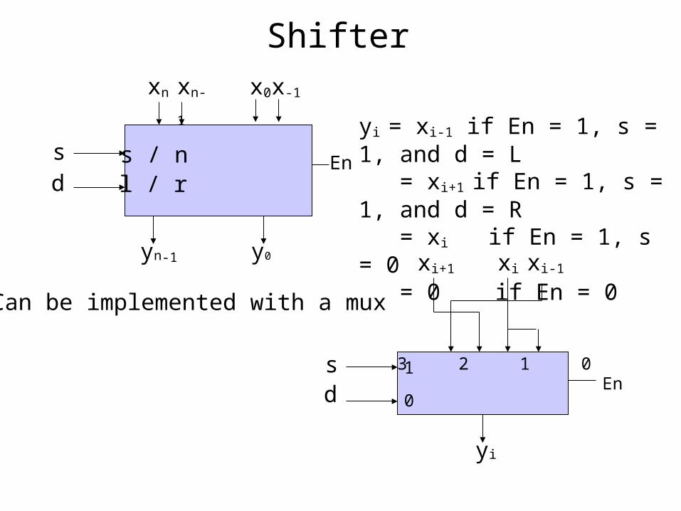
Shifter
Can be implemented with a mux
sd
yi
En1
0
3 2 1 0
xi+1 xi-1xi
sd
xn x0 x-1xn-1
yn-1 y0
Ens / nl / r
yi = xi-1 if En = 1, s = 1, and d = L = xi+1 if En = 1, s = 1, and d = R = xi if En = 1, s = 0 = 0 if En = 0

Barrel Shifter
O or 1 shift
O or 2 shift
O or 4 shift
x
s0
s1
s2
y
0 1 0 1 0 1
0 1 0 1 0 10 1 0 1
0 1 0 1 0 10 1 0 1 0 1
shift

41
Shifters as Multipliers and Dividers
• A left shift by N bits multiplies a number by 2N
– Ex: 00001 << 2 = 00100 (1 × 22 = 4)
– Ex: 11101 << 2 = 10100 (-3 × 22 = -12)
• The arithmetic right shift by N divides a number by 2N
– Ex: 01000 >>> 2 = 00010 (8 ÷ 22 = 2)
– Ex: 10000 >>> 2 = 11100 (-16 ÷ 22 = -4)

42
Multipliers• Steps of multiplication for both decimal and
binary numbers:– Partial products are formed by multiplying a single
digit of the multiplier with the entire multiplicand
– Shifted partial products are summed to form the result
Decimal Binary230
42x01010111
5 x 7 = 35
460920+9660
01010101
01010000
x
+0100011
230 x 42 = 9660
multipliermultiplicand
partialproducts
result
43
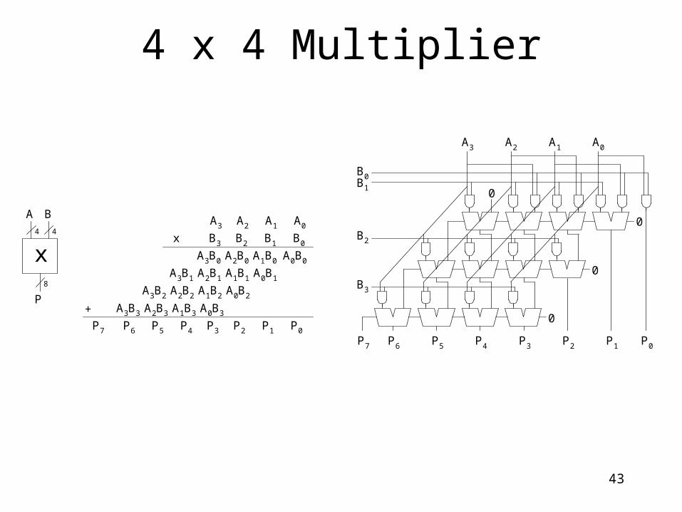
4 x 4 Multiplier
x
x
A B
P
B3 B2 B1 B0
A3B0 A2B0 A1B0 A0B0
A3 A2 A1 A0
A3B1 A2B1 A1B1 A0B1
A3B2 A2B2 A1B2 A0B2
A3B3 A2B3 A1B3 A0B3+
P7 P6 P5 P4 P3 P2 P1 P0
0
P2
0
0
0
P1 P0P5 P4 P3P7 P6
A3 A2 A1 A0
B0B1
B2
B3
44
8

44
Division Algorithm• Q = A/B• R: remainder• D: difference
R = A
for i = N-1 to 0
D = R - B
if D < 0 then Qi = 0, R’ = R // R < B
else Qi = 1, R’ = D // R B
R = 2R’

45
4 x 4 Divider