XCvhd: Combinational VHDL Examples -...
30
Combinational VHDL Examples XCvhd–1 Supplementary material to accompany Digital Design Principles and Practices, Fourth Edition, by John F. Wakerly. ISBN 0-13-186389-4. 2006 Pearson Education, Inc., Upper Saddle River, NJ. All rights reserved. This material is protected under all copyright laws as they currently exist. No portion of this material may be reproduced, in any form or by any means, without permission in writing by the publisher. XCvhd: Combinational VHDL Examples This section shows combinational design examples using VHDL. XCvhd.1 Barrel Shifter A barrel shifter is a combinational logic circuit with n data inputs, n data outputs, and a set of control inputs that specify how to shift the data between input and output. A barrel shifter that is part of a microprocessor CPU can typically specify the direction of shift (left or right), the type of shift (circular, arithmetic, or logical), and the amount of shift (typically 0 to n – 1 bits, but sometimes 1 to n bits). In this subsection we’ll look at the design of a 16-bit barrel shifter that does six different types of shifts, as specified by a 3-bit shift-mode input C[2:0]. A 4-bit shift-amount input S[3:0] specifies the amount of shift. For example, if C specifies a left-circular shift and the input word is ABCDEFGHIJKLMNOP (where each letter represents one bit), and S[3:0] is 0101 (5), then the output word is FGHIJKLMNOPABCDE. We show in Section XCbb.1 at DDPPonline how to build a simple barrel shifter using MSI building blocks; this circuit performed only left circular shifts. In Section XCabl.1 , we show how to define a more capable barrel shifter using ABEL, but we also point out that PLDs are normally unsuitable for realizing barrel shifters. In this section we’ll show how VHDL can be used to describe both the behavior and structure of barrel shifters for FPGA or ASIC realization. The shift types for this example are listed in Table XCvhd-1—circular, logical, and arithmetic, each with directions left and right. Table XCvhd-2 on the next page is a behavioral VHDL program for a 16-bit barrel shifter that performs any of six different combinations of shift type and direction. As shown in the entity declaration, a 4-bit control input S gives the shift amount, and a 3-bit control input C gives the shift mode (type and direction). We used the std_logic_arith package and defined the shift amount S to be type UNSIGNED so we could later use the CONV_INTEGER function in that package. Notice that the entity declaration includes six constant definitions that establish the correspondence between shift modes and the value of C. Although we didn’t discuss it in Section 5.3, VHDL allows you to put constant, type, Shift Type Name Code Note Table XCvhd-1 Shift types and codings for a barrel shifter. Left rotate Lrotate 000 Wrap-around Right rotate Rrotate 001 Wrap-around Left logical Llogical 010 0 into LSB Right logical Rlogical 011 0 into MSB Left arithmetic Larith 100 0 into LSB Right arithmetic Rarith 101 Replicate MSB barrel shifter
-
Upload
truonglien -
Category
Documents
-
view
253 -
download
0
Transcript of XCvhd: Combinational VHDL Examples -...

Combinational VHDL Examples XCvhd–1
Supplementary material to accompany Digital Design Principles and Practices, Fourth Edition, by John F. Wakerly. ISBN 0-13-186389-4. 2006 Pearson Education, Inc., Upper Saddle River, NJ. All rights reserved.
This material is protected under all copyright laws as they currently exist. No portion of this material may be reproduced, in any form or by any means, without permission in writing by the publisher.
XCvhd: Combinational VHDL ExamplesThis section shows combinational design examples using VHDL.
XCvhd.1 Barrel ShifterA barrel shifter is a combinational logic circuit with n data inputs, n dataoutputs, and a set of control inputs that specify how to shift the data betweeninput and output. A barrel shifter that is part of a microprocessor CPU cantypically specify the direction of shift (left or right), the type of shift (circular,arithmetic, or logical), and the amount of shift (typically 0 to n – 1 bits, butsometimes 1 to n bits).
In this subsection we’ll look at the design of a 16-bit barrel shifter that doessix different types of shifts, as specified by a 3-bit shift-mode input C[2:0]. A4-bit shift-amount input S[3:0] specifies the amount of shift. For example, if Cspecifies a left-circular shift and the input word is ABCDEFGHIJKLMNOP(where each letter represents one bit), and S[3:0] is 0101 (5), then the outputword is FGHIJKLMNOPABCDE.
We show in Section XCbb.1 at DDPPonline how to build a simple barrelshifter using MSI building blocks; this circuit performed only left circular shifts.In Section XCabl.1, we show how to define a more capable barrel shifter usingABEL, but we also point out that PLDs are normally unsuitable for realizingbarrel shifters. In this section we’ll show how VHDL can be used to describeboth the behavior and structure of barrel shifters for FPGA or ASIC realization.
The shift types for this example are listed in Table XCvhd-1—circular,logical, and arithmetic, each with directions left and right. Table XCvhd-2 on thenext page is a behavioral VHDL program for a 16-bit barrel shifter that performsany of six different combinations of shift type and direction. As shown inthe entity declaration, a 4-bit control input S gives the shift amount, and a3-bit control input C gives the shift mode (type and direction). We used thestd_logic_arith package and defined the shift amount S to be type UNSIGNEDso we could later use the CONV_INTEGER function in that package.
Notice that the entity declaration includes six constant definitions thatestablish the correspondence between shift modes and the value of C. Althoughwe didn’t discuss it in Section 5.3, VHDL allows you to put constant, type,
Shift Type Name Code Note Table XCvhd-1Shift types and codings for a barrel shifter.
Left rotate Lrotate 000 Wrap-around
Right rotate Rrotate 001 Wrap-around
Left logical Llogical 010 0 into LSB
Right logical Rlogical 011 0 into MSB
Left arithmetic Larith 100 0 into LSB
Right arithmetic Rarith 101 Replicate MSB
barrel shifter

Combinational VHDL Examples XCvhd–2
Supplementary material to accompany Digital Design Principles and Practices, Fourth Edition, by John F. Wakerly. ISBN 0-13-186389-4. 2006 Pearson Education, Inc., Upper Saddle River, NJ. All rights reserved.
This material is protected under all copyright laws as they currently exist. No portion of this material may be reproduced, in any form or by any means, without permission in writing by the publisher.
Table XCvhd-2 VHDL behavioral description of a 6-function barrel shifter.
library IEEE;use IEEE.std_logic_1164.all;use IEEE.std_logic_arith.all;
entity barrel16 is port ( DIN: in STD_LOGIC_VECTOR (15 downto 0); -- Data inputs S: in UNSIGNED (3 downto 0); -- Shift amount, 0-15 C: in STD_LOGIC_VECTOR (2 downto 0); -- Mode control DOUT: out STD_LOGIC_VECTOR (15 downto 0) -- Data bus output ); constant Lrotate: STD_LOGIC_VECTOR := "000"; -- Define the coding of constant Rrotate: STD_LOGIC_VECTOR := "001"; -- the different shift modes constant Llogical: STD_LOGIC_VECTOR := "010"; constant Rlogical: STD_LOGIC_VECTOR := "011"; constant Larith: STD_LOGIC_VECTOR := "100"; constant Rarith: STD_LOGIC_VECTOR := "101";end barrel16;
architecture barrel16_behavioral of barrel16 issubtype DATAWORD is STD_LOGIC_VECTOR(15 downto 0);
function Vrol (D: DATAWORD; S: UNSIGNED) return DATAWORD is variable N: INTEGER; variable TMPD: DATAWORD; begin N := CONV_INTEGER(S); TMPD := D; for i in 1 to N loop TMPD := TMPD(14 downto 0) & TMPD(15); end loop; return TMPD; end Vrol;
...
beginprocess(DIN, S, C) begin case C is when Lrotate => DOUT <= Vrol(DIN,S); when Rrotate => DOUT <= Vror(DIN,S); when Llogical => DOUT <= Vsll(DIN,S); when Rlogical => DOUT <= Vsrl(DIN,S); when Larith => DOUT <= Vsla(DIN,S); when Rarith => DOUT <= Vsra(DIN,S); when others => DOUT <= DIN; end case; end process;end barrel16_behavioral;

Combinational VHDL Examples XCvhd–3
Supplementary material to accompany Digital Design Principles and Practices, Fourth Edition, by John F. Wakerly. ISBN 0-13-186389-4. 2006 Pearson Education, Inc., Upper Saddle River, NJ. All rights reserved.
This material is protected under all copyright laws as they currently exist. No portion of this material may be reproduced, in any form or by any means, without permission in writing by the publisher.
signal, and other declarations within an entity declaration. It makes sense todefine such items within the entity declaration only if they must be the same inany architecture. In this case, we are pinning down the shift-mode encodings, sothey should go here. Other items should go in the architecture definition.
In the architecture part of the program we define six functions, one for eachkind of shift on a 16-bit STD_LOGIC_VECTOR. We defined the subtype DATAWORDto save typing in the function definitions.
Table XCvhd-2 shows the details of only the first function (Vrol); the restare similar with only a one-line change. We define a variable N for converting theshift-amount S into an integer for the for loop. We also assign the input vector Dto a local variable TMPD, which is shifted N times in the for loop. In the body ofthe for loop, a single assignment statement takes a 15-bit slice of the data word[TMPD (14 downto 0)] and uses concatenation [&] to put it back together with thebit that “falls off” the left end [TMPD(15)]. Other shift types can be describedwith similar operations. Note that the shift functions might not be defined inother, nonbehavioral descriptions of the barrel16 entity, for example instructural architectures.
The “concurrent statements” part of the architecture is a single process thathas all of the entity’s inputs in its sensitivity list. Within this process, a casestatement assigns a result to DOUT by calling the appropriate function based onthe value of the mode-control input C.
The process in Table XCvhd-2 is a nice behavioral description of the barrelshifter, but most synthesis tools cannot synthesize a circuit from it. The problemis that most tools require the range of a for loop to be static at the time it isanalyzed. The range of the for loop in the Vrol function is dynamic; it dependson the value of input signal S when the circuit is operating.
Well, that’s OK; it’s hard to predict what kind of circuit the synthesis toolwould come up with even if it could handle a dynamic for range. This is anexample where we designers should take a little more control over the circuitstructure to obtain a reasonably fast, efficient synthesis result.
In Figure XCbb-2 in Section XCbb.1 we showed how to design a 16-bitbarrel shifter for left circular shifts using MSI building blocks. We used acascade of four 16-bit, 2-input multiplexers to shift their inputs by 0 or 1, 2, 4, or8 positions, depending on the values of S0 through S3, respectively. We canexpress the same kind of behavior and structure using the VHDL program
ROLLINGYOUR OWN
VHDL-93 actually has built-in array operators, rol, ror, sll, srl, sla, and sra,corresponding to the shift operations that we defined in Table XCvhd-1. Since theseoperations are not provided in VHDL-87, we’ve defined our own functions inTable XCvhd-2. Well, actually we’ve defined only one of them (Vrol); the rest areleft as an exercise for the reader (Exercise XCvhd.1).

Combinational VHDL Examples XCvhd–4
Supplementary material to accompany Digital Design Principles and Practices, Fourth Edition, by John F. Wakerly. ISBN 0-13-186389-4. 2006 Pearson Education, Inc., Upper Saddle River, NJ. All rights reserved.
This material is protected under all copyright laws as they currently exist. No portion of this material may be reproduced, in any form or by any means, without permission in writing by the publisher.
shown in Table XCvhd-3. Even though the program uses a process and is“behavioral” in style, we can be pretty sure that most synthesis tools willgenerate a 2-input multiplexer for each “if” statement in the program, therebycreating a cascade similar to Figure XCbb-2 in Section XCbb.1.
Of course, our problem statement requires a barrel shifter that can shiftboth left and right. Table XCvhd-4 revises the previous program to do circularshifts in either direction. An additional input, DIR, specifies the shift direction, 0for left, 1 for right. Each rank of shifting is specified by a case statement thatpicks one of four possibilities based on the values of DIR and the bit of S thatcontrols that rank. Notice that we created local 2-bit variables CTRLi to hold thepair of values DIR and S(i); each case statement is controlled by one of thesevariables. You might like to eliminate these variables and simply control eachcase statement with a concatenation “DIR & S(i)”, but VHDL syntax doesn’tallow that because the type of this concatenation would be unknown.
A typical VHDL synthesis tool will generate a 3- or 4-input multiplexer foreach of the case statements in Table XCvhd-4. A good synthesis tool willgenerate only a 2-input multiplexer for the last case statement.
So, now we have a barrel shifter that will do left or right circular shifts, butwe’re not done yet—we need to take care of the logical and arithmetic shifts inboth directions. Figure XCvhd-1 shows our strategy for completing the design.We start out with the ROLR16 component that we just completed, and we useother logic to control the shift direction as a function of C.
Table XCvhd-3 VHDL program for a 16-bit barrel shifter for left circular shifts only.
library IEEE;use IEEE.std_logic_1164.all;
entity rol16 is port ( DIN: in STD_LOGIC_VECTOR(15 downto 0); -- Data inputs S: in STD_LOGIC_VECTOR (3 downto 0); -- Shift amount, 0-15 DOUT: out STD_LOGIC_VECTOR(15 downto 0) -- Data bus output );end rol16;
architecture rol16_arch of rol16 isbeginprocess(DIN, S) variable X, Y, Z: STD_LOGIC_VECTOR(15 downto 0); begin if S(0)='1' then X := DIN(14 downto 0) & DIN(15); else X := DIN; end if; if S(1)='1' then Y := X(13 downto 0) & X(15 downto 14); else Y := X; end if; if S(2)='1' then Z := Y(11 downto 0) & Y(15 downto 12); else Z := Y; end if; if S(3)='1' then DOUT <= Z(7 downto 0) & Z(15 downto 8); else DOUT <= Z; end if; end process;end rol16_arch;

Combinational VHDL Examples XCvhd–5
Supplementary material to accompany Digital Design Principles and Practices, Fourth Edition, by John F. Wakerly. ISBN 0-13-186389-4. 2006 Pearson Education, Inc., Upper Saddle River, NJ. All rights reserved.
This material is protected under all copyright laws as they currently exist. No portion of this material may be reproduced, in any form or by any means, without permission in writing by the publisher.
Table XCvhd-4 VHDL program for a 16-bit barrel shifter for left and right circular shifts.
library IEEE;use IEEE.std_logic_1164.all;
entity rolr16 is port ( DIN: in STD_LOGIC_VECTOR(15 downto 0); -- Data inputs S: in STD_LOGIC_VECTOR (3 downto 0); -- Shift amount, 0-15 DIR: in STD_LOGIC; -- Shift direction, 0=>L, 1=>R DOUT: out STD_LOGIC_VECTOR(15 downto 0) -- Data bus output );end rolr16;
architecture rol16r_arch of rolr16 isbeginprocess(DIN, S, DIR) variable X, Y, Z: STD_LOGIC_VECTOR(15 downto 0); variable CTRL0, CTRL1, CTRL2, CTRL3: STD_LOGIC_VECTOR(1 downto 0); begin CTRL0 := S(0) & DIR; CTRL1 := S(1) & DIR; CTRL2 := S(2) & DIR; CTRL3 := S(3) & DIR; case CTRL0 is when "00" | "01" => X := DIN; when "10" => X := DIN(14 downto 0) & DIN(15); when "11" => X := DIN(0) & DIN(15 downto 1); when others => null; end case; case CTRL1 is when "00" | "01" => Y := X; when "10" => Y := X(13 downto 0) & X(15 downto 14); when "11" => Y := X(1 downto 0) & X(15 downto 2); when others => null; end case; case CTRL2 is when "00" | "01" => Z := Y; when "10" => Z := Y(11 downto 0) & Y(15 downto 12); when "11" => Z := Y(3 downto 0) & Y(15 downto 4); when others => null; end case; case CTRL3 is when "00" | "01" => DOUT <= Z; when "10" | "11" => DOUT <= Z(7 downto 0) & Z(15 downto 8); when others => null; end case; end process;end rol16r_arch;
FIXUP(left)
FIXUP(right)
ROUT(15:0) FOUT(15:0)DOUT(15:0)ROLR16
other logic
ROUT(0) FOUT(15)
DIN(15:0)
S(3:0)
C(2:0)
Figure XCvhd-1Barrel-shifter components.
Combinational VHDL Examples XCvhd–6
Supplementary material to accompany Digital Design Principles and Practices, Fourth Edition, by John F. Wakerly. ISBN 0-13-186389-4. 2006 Pearson Education, Inc., Upper Saddle River, NJ. All rights reserved.
This material is protected under all copyright laws as they currently exist. No portion of this material may be reproduced, in any form or by any means, without permission in writing by the publisher.
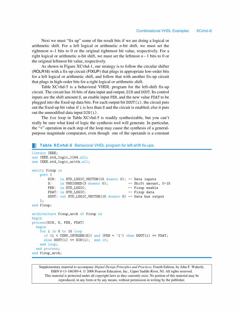
Next we must “fix up” some of the result bits if we are doing a logical orarithmetic shift. For a left logical or arithmetic n-bit shift, we must set therightmost n–1 bits to 0 or the original rightmost bit value, respectively. For aright logical or arithmetic n-bit shift, we must set the leftmost n – 1 bits to 0 orthe original leftmost bit value, respectively.
As shown in Figure XCvhd-1, our strategy is to follow the circular shifter(ROLR16) with a fix-up circuit (FIXUP) that plugs in appropriate low-order bitsfor a left logical or arithmetic shift, and follow that with another fix-up circuitthat plugs in high-order bits for a right logical or arithmetic shift.
Table XCvhd-5 is a behavioral VHDL program for the left-shift fix-upcircuit. The circuit has 16 bits of data input and output, DIN and DOUT. Its controlinputs are the shift amount S, an enable input FEN, and the new value FDAT to beplugged into the fixed-up data bits. For each output bit DOUT(i), the circuit putsout the fixed-up bit value if i is less than S and the circuit is enabled; else it putsout the unmodified data input DIN(i).
The for loop in Table XCvhd-5 is readily synthesizable, but you can’treally be sure what kind of logic the synthesis tool will generate. In particular,the “<” operation in each step of the loop may cause the synthesis of a general-purpose magnitude comparator, even though one of the operands is a constant
Table XCvhd-5 Behavioral VHDL program for left-shift fix-ups.
library IEEE;use IEEE.std_logic_1164.all;use IEEE.std_logic_arith.all;
entity fixup is port ( DIN: in STD_LOGIC_VECTOR(15 downto 0); -- Data inputs S: in UNSIGNED(3 downto 0); -- Shift amount, 0-15 FEN: in STD_LOGIC; -- Fixup enable FDAT: in STD_LOGIC; -- Fixup data DOUT: out STD_LOGIC_VECTOR(15 downto 0) -- Data bus output );end fixup;
architecture fixup_arch of fixup isbeginprocess(DIN, S, FEN, FDAT) begin for i in 0 to 15 loop if (i < CONV_INTEGER(S)) and (FEN = '1') then DOUT(i) <= FDAT; else DOUT(i) <= DIN(i); end if; end loop; end process;end fixup_arch;

Combinational VHDL Examples XCvhd–7
Supplementary material to accompany Digital Design Principles and Practices, Fourth Edition, by John F. Wakerly. ISBN 0-13-186389-4. 2006 Pearson Education, Inc., Upper Saddle River, NJ. All rights reserved.
This material is protected under all copyright laws as they currently exist. No portion of this material may be reproduced, in any form or by any means, without permission in writing by the publisher.
and each output could therefore be generated with no more than a handful ofgates. (In fact, the logic for “7 < CONV_INTEGER(S)” is just a wire, S(3)!) For astructural version of this function, see the box on this page.
For right shifts, fix-ups start from the opposite end of the data word, so itwould appear that we need a second version of the fix-up circuit. However, wecan use the original version if we just reverse the order of its input and outputbits, as we’ll soon see.
Table XCvhd-7 on the next page puts together a structural architecture forthe complete, 16-bit, 6-function barrel shifter using the design approach ofFigure XCvhd-1. The entity declaration for barrel16 is unchanged from theoriginal in Table XCvhd-2. The architecture declares two components, rolr16and fixup; these use our previous entity definitions. The statement part of thearchitecture instantiates rolr16 and fixup and has several assignment state-ments that create needed control signals (the “other logic” in Figure XCvhd-1).
Table XCvhd-6 Structural VHDL architecture for left-shift fix-ups.
architecture fixup_struc of fixup issignal FSEL: STD_LOGIC_VECTOR(15 downto 0); -- Fixup selectbegin FSEL(15) <= '0'; DOUT(15) <= DIN(15); U1: for i in 14 downto 0 generate FSEL(i) <= '1' when CONV_INTEGER(S) = i+1 else FSEL(i+1); DOUT(i) <= FDAT when (FSEL(i) = '1' and FEN = '1') else DIN(i); end generate;end fixup_struc;
A SERIAL FIX-UPSTRUCTURE
A structural architecture for the fix-up logic is shown in Table XCvhd-6. Here, wehave defined what is in effect an iterative circuit to create a 16-bit vector FSEL, whereFSEL(i) is 1 if bit i needs fixing up. We start by setting FSEL(15) to 0, since thatbit never needs fixing up. Then we note that for the remaining values of i, FSEL(i)should be 1 if S equals i+1 or if FSEL(i+1) is already asserted. Thus, the FSELassignment within the generate statement creates a serial chain of 2-input OR gates,where one input is asserted if S=i (decoded with a 4-input AND gate), and the otherinput is connected to the previous OR gate’s output. The DOUT(i) assignmentstatement creates 16 2-input multiplexers that select either DIN(i) or the fix-up data(FDAT), depending on the value of FSEL(i).
Although the serial realization is compact, it is very slow compared to one thatrealizes each FSEL output as a 2-level sum-of-products circuit. However, the longdelay may not matter, because the fix-up circuit appears near the end of the data path.If speed is still a problem, there is a zero-cost trick that cuts the delay in half (seeExercise XCvhd.4).

Combinational VHDL Examples XCvhd–8
Supplementary material to accompany Digital Design Principles and Practices, Fourth Edition, by John F. Wakerly. ISBN 0-13-186389-4. 2006 Pearson Education, Inc., Upper Saddle River, NJ. All rights reserved.
This material is protected under all copyright laws as they currently exist. No portion of this material may be reproduced, in any form or by any means, without permission in writing by the publisher.
For example, the first assignment statement asserts DIR_RIGHT if C speci-fies one of the right shifts. The enable inputs for the left and right fix-up circuitsare FIX_LEFT and FIX_RIGHT, asserted for left and right logical and arithmeticshifts. The fix-up data values are FIX_LEFT_DAT and FIX_RIGHT_DAT.
While all the statements in the architecture execute concurrently, they arelisted in Table XCvhd-7 in the order of the actual dataflow to improve read-ability. First, rolr16 is instantiated to perform the basic left or right circularshift as specified. Its outputs are hooked up to the inputs of the first fixup com-ponent (U2) to handle fix-ups for left logical and arithmetic shifts. Next comesU3, a generate statement that reverses the order of the data inputs for the nextfixup component (U4), which handles fix-ups for right logical and arithmeticshifts. Finally U5, another generate statement, undoes the bit reversing of U3.Note that in synthesis, U3 and U5 are merely permutations of wires.
Table XCvhd-7 VHDL structural architecture for the 6-function barrel shifter.
architecture barrel16_struc of barrel16 is
component rolr16 port ( DIN: in STD_LOGIC_VECTOR(15 downto 0); -- Data inputs S: in UNSIGNED(3 downto 0); -- Shift amount, 0-15 DIR: in STD_LOGIC; -- Shift direction, 0=>L, 1=>R DOUT: out STD_LOGIC_VECTOR(15 downto 0) -- Data bus output ); end component;
component fixup port ( DIN: in STD_LOGIC_VECTOR(15 downto 0); -- Data inputs S: in UNSIGNED(3 downto 0); -- Shift amount, 0-15 FEN: in STD_LOGIC; -- Fixup enable FDAT: in STD_LOGIC; -- Fixup data DOUT: out STD_LOGIC_VECTOR(15 downto 0) -- Data bus output ); end component;
signal DIR_RIGHT, FIX_RIGHT, FIX_RIGHT_DAT, FIX_LEFT, FIX_LEFT_DAT: STD_LOGIC;signal ROUT, FOUT, RFIXIN, RFIXOUT: STD_LOGIC_VECTOR(15 downto 0);
begin DIR_RIGHT <= '1' when C = Rrotate or C = Rlogical or C = Rarith else '0'; FIX_LEFT <= '1' when DIR_RIGHT='0' and (C = Llogical or C = Larith) else '0'; FIX_RIGHT <= '1' when DIR_RIGHT='1' and (C = Rlogical or C = Rarith) else '0'; FIX_LEFT_DAT <= DIN(0) when C = Larith else '0'; FIX_RIGHT_DAT <= DIN(15) when C = Rarith else '0'; U1: rolr16 port map (DIN, S, DIR_RIGHT, ROUT); U2: fixup port map (ROUT, S, FIX_LEFT, FIX_LEFT_DAT, FOUT); U3: for i in 0 to 15 generate RFIXIN(i) <= FOUT(15-i); end generate; U4: fixup port map (RFIXIN, S, FIX_RIGHT, FIX_RIGHT_DAT, RFIXOUT); U5: for i in 0 to 15 generate DOUT(i) <= RFIXOUT(15-i); end generate;end barrel16_struc;
Combinational VHDL Examples XCvhd–9
Supplementary material to accompany Digital Design Principles and Practices, Fourth Edition, by John F. Wakerly. ISBN 0-13-186389-4. 2006 Pearson Education, Inc., Upper Saddle River, NJ. All rights reserved.
This material is protected under all copyright laws as they currently exist. No portion of this material may be reproduced, in any form or by any means, without permission in writing by the publisher.
Many other architectures are possible for the original barrel16 entity. InExercise XCvhd.6, we suggest an architecture that enables the circular shiftingto be done by the rol16 entity, which uses only 2-input multiplexers, rather thanthe more expensive rolr16.
XCvhd.2 Simple Floating-Point EncoderAn unsigned binary integer B in the range 0 ≤ B < 211 can be represented by 11bits in “fixed-point” format, B = b10b9…b1b0. We can represent numbers inthe same range with less precision using only 7 bits in a floating-point notation,F = M ⋅ 2E, where M is a 4-bit mantissa m3m2m1m0 and E is a 3-bit exponente2e1e0. The smallest integer in this format is 0⋅20 and the largest is (24−1) ⋅ 27.
Given an 11-bit fixed-point integer B, we can convert it to our 7-bitfloating-point notation by “picking off” four high-order bits beginning with themost significant 1, for example,
The last term in each equation is a truncation error that results from the loss ofprecision in the conversion. Corresponding to this conversion operation, we canwrite the specification for a fixed-point to floating-point encoder circuit:
• A combinational circuit is to convert an 11-bit unsigned binary integer B intoa 7-bit floating-point number M,E, where M and E have 4 and 3 bits,respectively. The numbers have the relationship B = M ⋅2E + T, where T isthe truncation error, 0 ≤ T < 2E.
11010110100 = 1101 ⋅ 27 + 0110100
00100101111 = 1001 ⋅ 25 + 01111
00000111110 = 1111 ⋅ 22 + 10
00000001011 = 1011 ⋅ 20 + 0
00000000010 = 0010 ⋅ 20 + 0
INFORMATION-HIDING STYLE
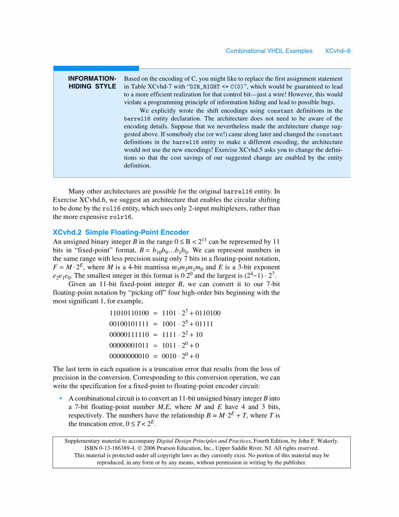
Based on the encoding of C, you might like to replace the first assignment statementin Table XCvhd-7 with “DIR_RIGHT <= C(0)”, which would be guaranteed to leadto a more efficient realization for that control bit—just a wire! However, this wouldviolate a programming principle of information hiding and lead to possible bugs.
We explicitly wrote the shift encodings using constant definitions in thebarrel16 entity declaration. The architecture does not need to be aware of theencoding details. Suppose that we nevertheless made the architecture change sug-gested above. If somebody else (or we!) came along later and changed the constantdefinitions in the barrel16 entity to make a different encoding, the architecturewould not use the new encodings! Exercise XCvhd.5 asks you to change the defini-tions so that the cost savings of our suggested change are enabled by the entitydefinition.
Combinational VHDL Examples XCvhd–10
Supplementary material to accompany Digital Design Principles and Practices, Fourth Edition, by John F. Wakerly. ISBN 0-13-186389-4. 2006 Pearson Education, Inc., Upper Saddle River, NJ. All rights reserved.
This material is protected under all copyright laws as they currently exist. No portion of this material may be reproduced, in any form or by any means, without permission in writing by the publisher.
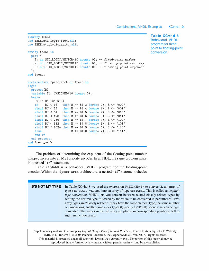
The problem of determining the exponent of the floating-point numbermapped nicely into an MSI priority encoder. In an HDL, the same problem mapsinto nested “if” statements.
Table XCvhd-8 is a behavioral VHDL program for the floating-pointencoder. Within the fpenc_arch architecture, a nested “if” statement checks
library IEEE;use IEEE.std_logic_1164.all;use IEEE.std_logic_arith.all;
entity fpenc is port ( B: in STD_LOGIC_VECTOR(10 downto 0); -- fixed-point number M: out STD_LOGIC_VECTOR(3 downto 0); -- floating-point mantissa E: out STD_LOGIC_VECTOR(2 downto 0) -- floating-point exponent );end fpenc;
architecture fpenc_arch of fpenc isbegin process(B) variable BU: UNSIGNED(10 downto 0); begin BU := UNSIGNED(B); if BU < 16 then M <= B( 3 downto 0); E <= "000"; elsif BU < 32 then M <= B( 4 downto 1); E <= "001"; elsif BU < 64 then M <= B( 5 downto 2); E <= "010"; elsif BU < 128 then M <= B( 6 downto 3); E <= "011"; elsif BU < 256 then M <= B( 7 downto 4); E <= "100"; elsif BU < 512 then M <= B( 8 downto 5); E <= "101"; elsif BU < 1024 then M <= B( 9 downto 6); E <= "110"; else M <= B(10 downto 7); E <= "111"; end if; end process;end fpenc_arch;
Table XCvhd-8Behavioral VHDL program for fixed-point to floating-point conversion.
B’S NOT MY TYPE In Table XCvhd-8 we used the expression UNSIGNED(B) to convert B, an array oftype STD_LOGIC_VECTOR, into an array of type UNSIGNED. This is called an explicittype conversion. VHDL lets you convert between related closely related types bywriting the desired type followed by the value to be converted in parentheses. Twoarray types are “closely related” if they have the same element type, the same numberof dimensions, and the same index types (typically INTEGER) or ones that can be typeconverted. The values in the old array are placed in corresponding positions, left toright, in the new array.

Combinational VHDL Examples XCvhd–11
Supplementary material to accompany Digital Design Principles and Practices, Fourth Edition, by John F. Wakerly. ISBN 0-13-186389-4. 2006 Pearson Education, Inc., Upper Saddle River, NJ. All rights reserved.
This material is protected under all copyright laws as they currently exist. No portion of this material may be reproduced, in any form or by any means, without permission in writing by the publisher.
the range of the input B and sets M and E appropriately. Notice that the programuses the std_logic_arith package; this is done to get the UNSIGNED type andthe comparison operations that go along with it, as we described inSection 6.9.7. Just to save typing, a variable BU is defined to hold the value of Bas converted to the UNSIGNED type; alternatively, we could have written“UNSIGNED(B)” in each nested “if” clause.
Although the code in Table XCvhd-8 is fully synthesizable, some synthe-sis tools may not be smart enough to recognize that the nested comparisonsrequire just one bit to be checked at each level, and might instead generate a full11-bit comparator at each level. Such logic would be a lot bigger and slower thanwhat otherwise would be possible. If faced with this problem, we can alwayswrite the architecture a little differently and more explicitly to help out the tool,as shown in Table XCvhd-9.
On the other hand, we might like to use the real comparators and spendeven more gates to improve the functionality of our design. In particular, thepresent design performs truncation rather than rounding when generating themantissa bits. A more accurate result is achieved with rounding, but this is amuch more complicated design. First, we will need an adder to add 1 to theselected mantissa bits when we round up. However, adding 1 when the mantissais already 1111 will bump us into the next exponent range, so we need to watchout for this case. Finally, we can never round up if the unrounded mantissa andexponent are 1111 and 111, because there’s no higher value in our floating-pointrepresentation to round to.
The program in Table XCvhd-10 on the next page performs rounding asdesired. The function round takes a selected 5-bit slice from the fixed-pointnumber and returns the four high-order bits, adding 1 if the LSB is 1. Thus, if wethink of the binary point as being just to the left of the LSB, rounding occurs if
architecture fpence_arch of fpenc isbegin
process(B)
begin
if B(10) = '1' then M <= B(10 downto 7); E <= "111";
elsif B(9) = '1' then M <= B( 9 downto 6); E <= "110";
elsif B(8) = '1' then M <= B( 8 downto 5); E <= "101";
elsif B(7) = '1' then M <= B( 7 downto 4); E <= "100";
elsif B(6) = '1' then M <= B( 6 downto 3); E <= "011";
elsif B(5) = '1' then M <= B( 5 downto 2); E <= "010";
elsif B(4) = '1' then M <= B( 4 downto 1); E <= "001";
else M <= B( 3 downto 0); E <= "000";
end if;
end process;
end fpence_arch;
Table XCvhd-9Alternative VHDL architecture for fixed-point to floating-point conversion.

Combinational VHDL Examples XCvhd–12
Supplementary material to accompany Digital Design Principles and Practices, Fourth Edition, by John F. Wakerly. ISBN 0-13-186389-4. 2006 Pearson Education, Inc., Upper Saddle River, NJ. All rights reserved.
This material is protected under all copyright laws as they currently exist. No portion of this material may be reproduced, in any form or by any means, without permission in writing by the publisher.
the truncated part of the mantissa is 1/2 or more. In each clause in the nested“if” statement in the process, the comparison value is selected so that roundingup will occur only if it does not “overflow,” pushing the result into the next expo-nent range. Otherwise, conversion and rounding occurs in the next clause. In the
architecture fpencr_arch of fpenc isfunction round (BSLICE: STD_LOGIC_VECTOR(4 downto 0)) return STD_LOGIC_VECTOR is variable BSU: UNSIGNED(3 downto 0); begin if BSLICE(0) = '0' then return BSLICE(4 downto 1); else BSU := UNSIGNED(BSLICE(4 downto 1)) + 1; return STD_LOGIC_VECTOR(BSU); end if; end;begin process(B) variable BU: UNSIGNED(10 downto 0); begin BU := UNSIGNED(B); if BU < 16 then M <= B( 3 downto 0); E <= "000"; elsif BU < 32-1 then M <= round(B( 4 downto 0)); E <= "001"; elsif BU < 64-2 then M <= round(B( 5 downto 1)); E <= "010"; elsif BU < 128-4 then M <= round(B( 6 downto 2)); E <= "011"; elsif BU < 256-8 then M <= round(B( 7 downto 3)); E <= "100"; elsif BU < 512-16 then M <= round(B( 8 downto 4)); E <= "101"; elsif BU < 1024-32 then M <= round(B( 9 downto 5)); E <= "110"; elsif BU < 2048-64 then M <= round(B(10 downto 6)); E <= "111"; else M <= "1111"; E <= "111"; end if; end process;end fpencr_arch;
Table XCvhd-10Behavioral VHDL architecture for fixed-point to floating-point conversion with rounding.
GOBBLE,GOBBLE
The rounding operation does not require a 4-bit adder, only an “incrementer,” sinceone of the addends is always 1. Some VHDL tools may synthesize the completeadder, while others may be smart enough to use an incrementer with far fewer gates.
In some cases it may not matter. The most sophisticated tools for FPGA andASIC design include gate gobblers. These programs look for gates with constantinputs and eliminate gates or gate inputs as a result. For example, an AND-gate inputwith a constant 1 applied to it can be eliminated, and an AND gate with a constant-0input can be replaced with a constant-0 signal.
A gate-gobbler program propagates the effects of constant inputs as far aspossible in a circuit. Thus, it can transform a 4-bit adder with a constant-1 input intoa more economical 4-bit incrementer.
Combinational VHDL Examples XCvhd–13
Supplementary material to accompany Digital Design Principles and Practices, Fourth Edition, by John F. Wakerly. ISBN 0-13-186389-4. 2006 Pearson Education, Inc., Upper Saddle River, NJ. All rights reserved.
This material is protected under all copyright laws as they currently exist. No portion of this material may be reproduced, in any form or by any means, without permission in writing by the publisher.
last clause, we ensure that we do not round up when we’re at the end of thefloating-point range.
Once again, synthesis results for this behavioral program may or may notbe efficient. Besides the multiple comparison statements, we now must worryabout the multiple 4-bit adders that might be synthesized as a result of themultiple calls to the round function. Restructuring the architecture so that onlya single adder is synthesized is left as an exercise (XCvhd.7).
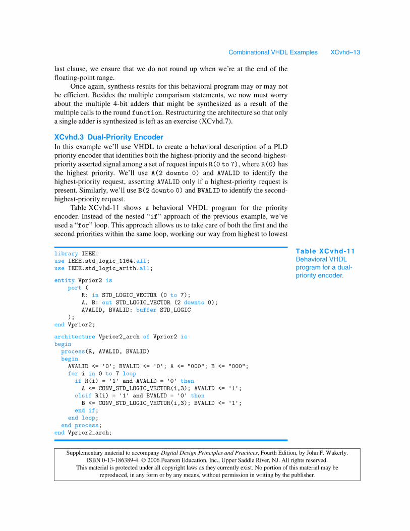
XCvhd.3 Dual-Priority EncoderIn this example we’ll use VHDL to create a behavioral description of a PLDpriority encoder that identifies both the highest-priority and the second-highest-priority asserted signal among a set of request inputs R(0 to 7), where R(0) hasthe highest priority. We’ll use A(2 downto 0) and AVALID to identify thehighest-priority request, asserting AVALID only if a highest-priority request ispresent. Similarly, we’ll use B(2 downto 0) and BVALID to identify the second-highest-priority request.
Table XCvhd-11 shows a behavioral VHDL program for the priorityencoder. Instead of the nested “if” approach of the previous example, we’veused a “for” loop. This approach allows us to take care of both the first and thesecond priorities within the same loop, working our way from highest to lowest
library IEEE;use IEEE.std_logic_1164.all;use IEEE.std_logic_arith.all;
entity Vprior2 is port ( R: in STD_LOGIC_VECTOR (0 to 7); A, B: out STD_LOGIC_VECTOR (2 downto 0); AVALID, BVALID: buffer STD_LOGIC );end Vprior2;
architecture Vprior2_arch of Vprior2 isbegin process(R, AVALID, BVALID) begin AVALID <= '0'; BVALID <= '0'; A <= "000"; B <= "000"; for i in 0 to 7 loop if R(i) = '1' and AVALID = '0' then A <= CONV_STD_LOGIC_VECTOR(i,3); AVALID <= '1'; elsif R(i) = '1' and BVALID = '0' then B <= CONV_STD_LOGIC_VECTOR(i,3); BVALID <= '1'; end if; end loop; end process;end Vprior2_arch;
Table XCvhd-11Behavioral VHDL program for a dual-priority encoder.

Combinational VHDL Examples XCvhd–14
Supplementary material to accompany Digital Design Principles and Practices, Fourth Edition, by John F. Wakerly. ISBN 0-13-186389-4. 2006 Pearson Education, Inc., Upper Saddle River, NJ. All rights reserved.
This material is protected under all copyright laws as they currently exist. No portion of this material may be reproduced, in any form or by any means, without permission in writing by the publisher.
priority. Besides std_logic_1164, the program uses the std_logic_arithpackage in order to get the CONV_STD_LOGIC_VECTOR function. We also wrotethis function explicitly in Table 5-25 on page 268.
Notice in the table that ports AVALID and BVALID are declared as modebuffer, because they are read within the architecture. If you were stuck with anentity definition that declared AVALID and BVALID as mode out, you could stilluse the same architecture approach, but you would have to declare localvariables corresponding to AVALID and BVALID within the process. Notice alsothat we included AVALID and BVALID in the process sensitivity list. Althoughthis is not strictly necessary, it prevents warnings that the compiler otherwisewould give about using the value of a signal that is not on the sensitivity list.
The nested “if” approach can also be used for the dual-priority encoder,but it yields a longer program with more accidents waiting to happen, as shownin Table XCvhd-12. On the other hand, it may yield a better synthesis result; theonly way to know with a particular tool is to synthesize the circuit and analyzethe results in terms of delay and cell or gate count.
Both nested “if” statements and “for” statements may lead to long delaychains in synthesis. To guarantee that you get a faster dual-priority encoder, youmust follow a structural or semistructural design approach. For example, you
architecture Vprior2i_arch of Vprior2 isbegin
process(R, A, AVALID, BVALID) begin
if R(0) = '1' then A <= "000"; AVALID <= '1'; elsif R(1) = '1' then A <= "001"; AVALID <= '1';
elsif R(2) = '1' then A <= "010"; AVALID <= '1'; elsif R(3) = '1' then A <= "011"; AVALID <= '1';
elsif R(4) = '1' then A <= "100"; AVALID <= '1'; elsif R(5) = '1' then A <= "101"; AVALID <= '1';
elsif R(6) = '1' then A <= "110"; AVALID <= '1'; elsif R(7) = '1' then A <= "111"; AVALID <= '1';
else A <= "000"; AVALID <= '0'; end if;
if R(1) = '1' and A /= "001" then B <= "001"; BVALID <= '1'; elsif R(2) = '1' and A /= "010" then B <= "010"; BVALID <= '1';
elsif R(3) = '1' and A /= "011" then B <= "011"; BVALID <= '1'; elsif R(4) = '1' and A /= "100" then B <= "100"; BVALID <= '1';
elsif R(5) = '1' and A /= "101" then B <= "101"; BVALID <= '1'; elsif R(6) = '1' and A /= "110" then B <= "110"; BVALID <= '1';
elsif R(7) = '1' and A /= "111" then B <= "111"; BVALID <= '1'; else B <= "000"; BVALID <= '0';
end if; end process;
end Vprior2i_arch;
Table XCvhd-12Alternative VHDL architecture for a dual-priority encoder.

Combinational VHDL Examples XCvhd–15
Supplementary material to accompany Digital Design Principles and Practices, Fourth Edition, by John F. Wakerly. ISBN 0-13-186389-4. 2006 Pearson Education, Inc., Upper Saddle River, NJ. All rights reserved.
This material is protected under all copyright laws as they currently exist. No portion of this material may be reproduced, in any form or by any means, without permission in writing by the publisher.
can start by writing a dataflow model of a fast 8-input priority encoder using theideas found in the 74x148 logic diagram (at DDPPonline in Section Enc) or in arelated ABEL program (Table 6-28 on page 414). Then you can put two of thesetogether in a structure that “knocks out” the highest-priority input in orderto find the second, as we did with MSI building blocks in Figure XCbb-5 inSection XCbb.3.
XCvhd.4 Cascading ComparatorsCascading comparators is something we typically would not do in a VHDLbehavioral model, because the language and the std_logic_arith package letus define comparators of any desired length directly. However, we may indeedneed to write structural or semistructural VHDL programs that hook up smallercomparator components in a specific way to obtain high performance.
A simple VHDL behavioral model of a 64-bit comparator with equals andgreater-than outputs is shown in Table XCvhd-13. This program uses the IEEEstd_logic_unsigned package, whose built-in comparison functions automati-cally treat all signals of type STD_LOGIC_VECTOR as unsigned integers.Although the program is fully synthesizable, the speed and size of the resultdepends on the “intelligence” of the particular tool that is used.
An alternative is to build the comparator by cascading smaller components,such as 8-bit comparators. Table XCvhd-14 on the next page is the behavioralmodel of an 8-bit comparator. A particular tool may or may not synthesize a veryfast comparator from this program, but it’s sure to be significantly faster than a64-bit comparator in any case.
Next, we can write a structural program that instantiates eight of these 8-bitcomparators and hooks up their individual outputs through additional logic tocalculate the overall comparison result. One way to do this is shown inTable XCvhd-15. A generate statement creates not only the individual 8-bit
library IEEE;use IEEE.std_logic_1164.all;use IEEE.std_logic_unsigned.all;
entity comp64 is port ( A, B: in STD_LOGIC_VECTOR (63 downto 0); EQ, GT: out STD_LOGIC );end comp64;
architecture comp64_arch of comp64 isbegin EQ <= '1' when A = B else '0'; GT <= '1' when A > B else '0';end comp64_arch;
Table XCvhd-13Behavioral VHDL program for a 64-bit comparator.

Combinational VHDL Examples XCvhd–16
Supplementary material to accompany Digital Design Principles and Practices, Fourth Edition, by John F. Wakerly. ISBN 0-13-186389-4. 2006 Pearson Education, Inc., Upper Saddle River, NJ. All rights reserved.
This material is protected under all copyright laws as they currently exist. No portion of this material may be reproduced, in any form or by any means, without permission in writing by the publisher.
comparators but also cascading logic that serially builds up the overall resultfrom most significant to least significant stage.
An unsophisticated tool could synthesize a slow iterative comparatorcircuit for our original 64-bit comparator architecture in Table XCvhd-13. Inthis situation, the architecture in Table XCvhd-15 yields a faster synthesized cir-cuit because it explicitly “pulls” out the cascading information for each 8-bitslice and combines it in a faster combinational circuit (just 8 levels of AND-ORlogic, not 64). A more sophisticated tool might flatten the 8-bit comparator intofaster, non-iterative structure similar to the 74x682 MSI comparator(Figure 6-82 on page 464), and it might flatten our iterative cascading logic inTable XCvhd-15 into two-level sum-of-products equations similar to the ones inthe ABEL solution in Table XCabl-7 in Section XCabl.4.
library IEEE;use IEEE.std_logic_1164.all;use IEEE.std_logic_unsigned.all;
entity comp8 is port ( A, B: in STD_LOGIC_VECTOR (7 downto 0); EQ, GT: out STD_LOGIC );end comp8;
architecture comp8_arch of comp8 isbegin EQ <= '1' when A = B else '0'; GT <= '1' when A > B else '0';end comp8_arch;
Table XCvhd-14VHDL program for an 8-bit comparator.
Table XCvhd-15 VHDL structural architecture for a 64-bit comparator.
architecture comp64s_arch of comp64 iscomponent comp8 port ( A, B: in STD_LOGIC_VECTOR (7 downto 0); EQ, GT: out STD_LOGIC);end component;signal EQ8, GT8: STD_LOGIC_VECTOR (7 downto 0); -- =, > for 8-bit slicesignal SEQ, SGT: STD_LOGIC_VECTOR (8 downto 0); -- serial chain of slice resultsbegin SEQ(8) <= '1'; SGT(8) <= '0'; U1: for i in 7 downto 0 generate U2: comp8 port map (A(7+i*8 downto i*8), B(7+i*8 downto i*8), EQ8(i), GT8(i)); SEQ(i) <= SEQ(i+1) and EQ8(i); SGT(i) <= SGT(i+1) or (SEQ(i+1) and GT8(i)); end generate; EQ <= SEQ(0); GT <= SGT(0);end comp64s_arch;

Combinational VHDL Examples XCvhd–17
Supplementary material to accompany Digital Design Principles and Practices, Fourth Edition, by John F. Wakerly. ISBN 0-13-186389-4. 2006 Pearson Education, Inc., Upper Saddle River, NJ. All rights reserved.
This material is protected under all copyright laws as they currently exist. No portion of this material may be reproduced, in any form or by any means, without permission in writing by the publisher.
XCvhd.5 Mode-Dependent ComparatorFor the next example, let us suppose we have a system in which we need to com-pare two 32-bit words under normal circumstances, but where we mustsometimes ignore one or two low-order bits of the input words. The operatingmode of the comparator is specified by two mode-control bits, M1 and M0, asshown in Table XCvhd-16.
The desired functionality can be obtained very easily in VHDL using acase statement to select the behavior by mode, as shown in the program inTable XCvhd-17. This is a perfectly good behavioral description that is alsofully synthesizable. However, it has one major drawback in synthesis—it will, inall likelihood, cause the creation of three separate equality and magnitude
M1 M0 Comparison Table XCvhd-16Mode-control bits for the mode-dependent comparator.
0 0 32-bit0 1 31-bit1 0 30-bit1 1 not used
Table XCvhd-17 VHDL behavioral architecture of a 32-bit mode-dependent comparator.
library IEEE;use IEEE.std_logic_1164.all;use IEEE.std_logic_unsigned.all;
entity Vmodecmp is port ( M: in STD_LOGIC_VECTOR (1 downto 0); -- mode A, B: in STD_LOGIC_VECTOR (31 downto 0); -- unsigned integers EQ, GT: out STD_LOGIC ); -- comparison resultsend Vmodecmp;
architecture Vmodecmp_arch of Vmodecmp isbegin process (M, A, B) begin case M is when "00" => if A = B then EQ <= '1'; else EQ <= '0'; end if; if A > B then GT <= '1'; else GT <= '0'; end if; when "01" => if A(31 downto 1) = B(31 downto 1) then EQ <= '1'; else EQ <= '0'; end if; if A(31 downto 1) > B(31 downto 1) then GT <= '1'; else GT <= '0'; end if; when "10" => if A(31 downto 2) = B(31 downto 2) then EQ <= '1'; else EQ <= '0'; end if; if A(31 downto 2) > B(31 downto 2) then GT <= '1'; else GT <= '0'; end if; when others => EQ <= '0'; GT <= '0'; end case; end process; end Vmodecmp_arch;

Combinational VHDL Examples XCvhd–18
Supplementary material to accompany Digital Design Principles and Practices, Fourth Edition, by John F. Wakerly. ISBN 0-13-186389-4. 2006 Pearson Education, Inc., Upper Saddle River, NJ. All rights reserved.
This material is protected under all copyright laws as they currently exist. No portion of this material may be reproduced, in any form or by any means, without permission in writing by the publisher.
comparators (32-, 31-, and 30-bit), one for each case in the case statement. Theindividual comparators may or may not be fast, as discussed in the previoussubsection, but we won’t worry about speed for this example.
A more efficient alternative is to perform just one comparison for the 30high-order bits of the inputs, using additional logic that is dependent on mode togive a final result using the low-order bits as necessary. This approach is shownin Table XCvhd-18. Two variables, EQ30 and GT30, are used within the processto hold the results of the comparison of the 30 high-order bits. A case statementsimilar to the previous architecture’s is then used to obtain the final results as afunction of the mode. If desired, the speed of the 30-bit comparison can beoptimized using the methods discussed in the preceding subsection.
XCvhd.6 Ones CounterSeveral important algorithms include the step of counting the number of “1” bitsin a data word. In fact, some microprocessor instruction sets have been extendedrecently to include ones counting as a basic instruction. In this example, let ussuppose that we have a requirement to design a combinational circuit that countsones in a 32-bit word as part of the arithmetic and logic unit of a microprocessor.
Ones counting can be described very easily by a behavioral VHDLprogram, as shown in Table XCvhd-19. This program is fully synthesizable, butit may generate a very slow, inefficient realization with 32 5-bit adders in series.
Table XCvhd-18 More efficient architecture for a 32-bit mode-dependent comparator.
architecture Vmodecpe_arch of Vmodecmp isbegin process (M, A, B) variable EQ30, GT30: STD_LOGIC; -- 30-bit comparison results begin if A(31 downto 2) = B(31 downto 2) then EQ30 := '1'; else EQ30 := '0'; end if; if A(31 downto 2) > B(31 downto 2) then GT30 := '1'; else GT30 := '0'; end if; case M is when "00" => if EQ30='1' and A(1 downto 0) = B(1 downto 0) then EQ <= '1'; else EQ <= '0'; end if; if GT30='1' or (EQ30='1' and A(1 downto 0) > B(1 downto 0)) then GT <= '1'; else GT <= '0'; end if; when "01" => if EQ30='1' and A(1) = B(1) then EQ <= '1'; else EQ <= '0'; end if; if GT30='1' or (EQ30='1' and A(1) > B(1)) then GT <= '1'; else GT <= '0'; end if; when "10" => EQ <= EQ30; GT <= GT30; when others => EQ <= '0'; GT <= '0'; end case; end process; end Vmodecpe_arch;

Combinational VHDL Examples XCvhd–19
Supplementary material to accompany Digital Design Principles and Practices, Fourth Edition, by John F. Wakerly. ISBN 0-13-186389-4. 2006 Pearson Education, Inc., Upper Saddle River, NJ. All rights reserved.
This material is protected under all copyright laws as they currently exist. No portion of this material may be reproduced, in any form or by any means, without permission in writing by the publisher.
To synthesize a more efficient realization of the ones counter, we mustcome up with an efficient structure and then write an architecture that describesit. Such a structure is the adder tree shown in Figure XCvhd-2. A full adder (FA)adds three input bits to produce a 2-bit sum. Pairs of 2-bit numbers are added by2-bit adders (ADDER2), each of which also has a carry input that can add another
library IEEE;use IEEE.std_logic_1164.all;use IEEE.std_logic_unsigned.all;
entity Vcnt1s is port ( D: in STD_LOGIC_VECTOR (31 downto 0); SUM: out STD_LOGIC_VECTOR (5 downto 0) );end Vcnt1s;
architecture Vcnt1s_arch of Vcnt1s isbegin process (D) variable S: STD_LOGIC_VECTOR(5 downto 0); begin S := "000000"; for i in 0 to 31 loop if D(i) = '1' then S := S + "000001"; end if; end loop; SUM <= S; end process;end Vcnt1s_arch;
Table XCvhd-19Behavioral VHDL program for a 32-bit ones counter.
ADDER4
D[30]
4
FAD[2:0]
FAD[5:3]ADDER2
FAD[8:6]
FAD[11:9]ADDER2
ADDER3
2
2
2
2
3
3
D[25]
D[24]
D[28]
FAD[14:12]
FAD[17:15]ADDER2
FAD[20:18]
FAD[23:21]ADDER2
ADDER3
2
2
2
2
3
3
D[27]
D[26]
D[29]
4
INCR5
D[31]
5 6SUM[5:0]
signal names P[0:7][1:0] Q[0:3][2:0] R[0:1][3:0] S[4:0]
Figure XCvhd-2 Structure of a 32-bit ones counter.

Combinational VHDL Examples XCvhd–20
Supplementary material to accompany Digital Design Principles and Practices, Fourth Edition, by John F. Wakerly. ISBN 0-13-186389-4. 2006 Pearson Education, Inc., Upper Saddle River, NJ. All rights reserved.
This material is protected under all copyright laws as they currently exist. No portion of this material may be reproduced, in any form or by any means, without permission in writing by the publisher.
architecture Vcnt1str_arch of Vcnt1str is
component FA port ( A, B, CI: in STD_LOGIC; S, CO: out STD_LOGIC );end component;
component ADDER2 port ( A, B: in STD_LOGIC_VECTOR(1 downto 0); CI: in STD_LOGIC; S: out STD_LOGIC_VECTOR(2 downto 0) );end component;
component ADDER3 port ( A, B: in STD_LOGIC_VECTOR(2 downto 0); CI: in STD_LOGIC; S: out STD_LOGIC_VECTOR(3 downto 0) );end component;
component ADDER4 port ( A, B: in STD_LOGIC_VECTOR(3 downto 0); CI: in STD_LOGIC; S: out STD_LOGIC_VECTOR(4 downto 0) );end component;
component INCR5 port ( A: in STD_LOGIC_VECTOR(4 downto 0); CI: in STD_LOGIC; S: out STD_LOGIC_VECTOR(5 downto 0) );end component;
type Ptype is array (0 to 7) of STD_LOGIC_VECTOR(1 downto 0);type Qtype is array (0 to 3) of STD_LOGIC_VECTOR(2 downto 0);type Rtype is array (0 to 1) of STD_LOGIC_VECTOR(3 downto 0);signal P: Ptype; signal Q: Qtype; signal R: Rtype;signal S: STD_LOGIC_VECTOR(4 downto 0);
begin U1: for i in 0 to 7 generate U1C: FA port map (D(3*i), D(3*i+1), D(3*i+2), P(i)(0), P(i)(1)); end generate; U2: for i in 0 to 3 generate U2C: ADDER2 port map (P(2*i), P(2*i+1), D(24+i), Q(i)); end generate; U3: for i in 0 to 1 generate U3C: ADDER3 port map (Q(2*i), Q(2*i+1), D(28+i), R(i)); end generate; U4: ADDER4 port map (R(0), R(1), D(30), S); U5: INCR5 port map (S, D(31), SUM); end Vcnt1str_arch;
Table XCvhd-20VHDL structural architecture for a 32-bit ones counter.

Combinational VHDL Examples XCvhd–21
Supplementary material to accompany Digital Design Principles and Practices, Fourth Edition, by John F. Wakerly. ISBN 0-13-186389-4. 2006 Pearson Education, Inc., Upper Saddle River, NJ. All rights reserved.
This material is protected under all copyright laws as they currently exist. No portion of this material may be reproduced, in any form or by any means, without permission in writing by the publisher.
1-bit input to its sum. The resulting 3-bit sums are combined by 3-bit adders(ADDER3), and the final pair of 4-bit sums are combined in a 4-bit adder(ADDER4). By making use of the available carry inputs, this tree structure cancombine 31 bits. A separate 5-bit incrementer is used at the end to handle the oneremaining input bit.
The structure of Figure XCvhd-2 can be created nicely by a structuralVHDL architecture, as shown in Table XCvhd-20. The program begins bydeclaring all of the components that will be used in the design, corresponding tothe blocks in the figure.
The letter under each column of signals in Figure XCvhd-2 corresponds tothe name used for that signal in the program. Each of signals P, Q, and R is anarray with one STD_LOGIC_VECTOR per connection in the correspondingcolumn. The program defines a corresponding type for each of these, followedby the actual signal declaration.
The program in Table XCvhd-20 makes good use of generate statementsto create the multiple adder components on the lefthand side of the figure—eightFAs, four ADDER2s, and two ADDER3s. Finally, it instantiates one each ofADDER4 and INCR5.
The definitions of the ones counter’s individual component entities andarchitectures, from FA to INCR, can be made in separate structural or behavioralprograms. For example, Table XCvhd-21 is a structural program for FA. The restof the components are left as exercises (XCvhd.15–XCvhd.17).
library IEEE;use IEEE.std_logic_1164.all;
entity FA is port ( A, B, CI: in STD_LOGIC; S, CO: out STD_LOGIC );end FA;
architecture FA_arch of FA isbegin S <= A xor B xor CI; CO <= (A and B) or (A and CI) or (B and CI);end FA_arch;
Table XCvhd-21Structural VHDL program for a full adder.

Combinational VHDL Examples XCvhd–22
Supplementary material to accompany Digital Design Principles and Practices, Fourth Edition, by John F. Wakerly. ISBN 0-13-186389-4. 2006 Pearson Education, Inc., Upper Saddle River, NJ. All rights reserved.
This material is protected under all copyright laws as they currently exist. No portion of this material may be reproduced, in any form or by any means, without permission in writing by the publisher.
XCvhd.7 Tic-Tac-ToeOur last example is the design of a combinational circuit that picks a player’snext move in the game of Tic-Tac-Toe. The first thing we’ll do is decide on astrategy for picking the next move. Let us try to emulate the typical human’sstrategy by following the decision steps below:
1. Look for a row, column, or diagonal that has two of my marks (X or O,depending on which player I am) and one empty cell. If one exists, placemy mark in the empty cell; I win!
2. Else, look for a row, column, or diagonal that has two of my opponent’smarks and one empty cell. If one exists, place my mark in the empty cellto block a potential win by my opponent.
3. Else, pick a cell based on experience. For example, if the middle cell isopen, it’s usually a good bet to take it. Otherwise, the corner cells are goodbets. Intelligent players can also notice and block a developing pattern bythe opponent or “look ahead” to pick a good move.
To avoid confusion between “O” and “0” in our programs, we’ll call thesecond player “Y”. Now we can think about how to encode the inputs andoutputs of the circuit. The inputs represent the current state of the playing grid.There are nine cells, and each cell has one of three possible states (empty,occupied by X, occupied by Y). The circuit’s outputs represent the move to make,assuming that it is X’s turn. There are only nine possible moves that a player canmake, so the output can be encoded in just four bits.
There are several choices of how to code the state of one cell. Because thegame is symmetric, we choose a symmetric encoding that can help us later:
00 Cell is empty.
10 Cell is occupied by X.
01 Cell is occupied by Y.
So, we can encode the 3 × 3 grid’s state in 18 bits. Since VHDL supportsarrays, it is useful to define an array type, TTTgrid, that contains elements
TIC-TAC-TOE,IN CASE YOU
DIDN’T KNOW
The game of Tic-Tac-Toe is played by two players on a 3 × 3 grid of cells that areinitially empty. One player is “X” and the other is “O”. The players alternate inplacing their mark in an empty cell; “X” always goes first. The first player to get threeof his or her own marks in the same row, column, or diagonal wins. Although the firstplayer to move (X) has a slight advantage, it can be shown that a game between twointelligent players will always end in a draw; neither player will get three in a rowbefore the grid fills up.

Combinational VHDL Examples XCvhd–23
Supplementary material to accompany Digital Design Principles and Practices, Fourth Edition, by John F. Wakerly. ISBN 0-13-186389-4. 2006 Pearson Education, Inc., Upper Saddle River, NJ. All rights reserved.
This material is protected under all copyright laws as they currently exist. No portion of this material may be reproduced, in any form or by any means, without permission in writing by the publisher.
corresponding to the cells in the grid. Since this type will be used throughout ourTic-Tac-Toe project, it is convenient to put this definition, along with severalothers that we’ll come to, in a VHDL package, as shown in Table XCvhd-22.
It would be natural to define TTTgrid as a two-dimensional array ofSTD_LOGIC, but not all VHDL tools support two-dimensional arrays. Instead,we define it as an array of 3-bit STD_LOGIC_VECTORs, which is almost the samething. To represent the Tic-Tac-Toe grid, we’ll use two signals X and Y of thistype, where an element of a variable is 1 if the like-named player has a mark inthe corresponding cell. Figure XCvhd-3 shows the correspondence betweensignal names and cells in the grid.
library IEEE;use IEEE.std_logic_1164.all;
package TTTdefs is
type TTTgrid is array (1 to 3) of STD_LOGIC_VECTOR(1 to 3);subtype TTTmove is STD_LOGIC_VECTOR (3 downto 0);
constant MOVE11: TTTmove := "1000";constant MOVE12: TTTmove := "0100";constant MOVE13: TTTmove := "0010";constant MOVE21: TTTmove := "0001";constant MOVE22: TTTmove := "1100";constant MOVE23: TTTmove := "0111";constant MOVE31: TTTmove := "1011";constant MOVE32: TTTmove := "1101";constant MOVE33: TTTmove := "1110";constant NONE: TTTmove := "0000";
end TTTdefs;
Table XCvhd-22VHDL package with definitions for the Tic-Tac-Toe project.
Figure XCvhd-3Tic-Tac-Toe grid and VHDL signal names.X(1)(1)
Y(1)(1)1
1
3
2
2
3row
column
X(1)(2)
Y(1)(2)
X(1)(3)
Y(1)(3)
X(2)(1)
Y(2)(1)
X(2)(2)
Y(2)(2)
X(2)(3)
Y(2)(3)
X(3)(1)
Y(3)(1)
X(3)(2)
Y(3)(2)
X(3)(3)
Y(3)(3)

Combinational VHDL Examples XCvhd–24
Supplementary material to accompany Digital Design Principles and Practices, Fourth Edition, by John F. Wakerly. ISBN 0-13-186389-4. 2006 Pearson Education, Inc., Upper Saddle River, NJ. All rights reserved.
This material is protected under all copyright laws as they currently exist. No portion of this material may be reproduced, in any form or by any means, without permission in writing by the publisher.
The package in Table XCvhd-22 also defines a 4-bit type TTTmove forencoded moves. A player has nine possible moves, and one more code is used forthe case where no move is possible. This particular coding was chosen and usedin the package for no other reason than that it’s the same coding that was used inthe ABEL version of this example in Section XCabl.7. By defining the coding inthe package, we can easily change the definition later without having to changethe entities that use it (for example, see Exercise XCvhd.18).
Rather than try to design the Tic-Tac-Toe move-finding circuit as a singlemonolithic entity, it makes sense for us to try to partition it into smaller pieces. Infact, partitioning it along the lines of the three-step strategy at the beginning ofthis section seems like a good idea.
We note that steps 1 and 2 of our strategy are very similar; they differ onlyin reversing the roles of the player and the opponent. An entity that finds awinning move for me can also find a blocking move for my opponent. Lookingat this characteristic from another point of view, an entity that finds a winningmove for me can find a blocking move for me if the encodings for me and myopponent are swapped. Here’s where our symmetric encoding pays off—we canswap players merely by swapping signals X and Y.
With this in mind, we can use two copies of the same entity, TwoInRow, toperform steps 1 and 2 as shown in Figure XCvhd-4. Notice that signal X isconnected to the top input of the first TwoInRow entity, but to the bottom input ofthe second. A third entity, PICK, picks a winning move if one is available fromU1, else it picks a blocking move if available from U2, else it uses “experience”(step 3) to pick a move.
Table XCvhd-23 is a structural VHDL program for the top-level entity,GETMOVE. Besides the IEEE std_logic_1164 package, it uses our TTTdefspackage. Notice that the “use” clause for the TTTdefs packages specifies that itis stored in the “work” library, which is automatically created for our project.
X
Y
MOVE
TwoInRow
X
Y
PICK
WINMV
BLKMV
MOVE
X
Y
MOVE
9
4
4
9
9
9
4U1
U2
U3
X
Y
MOVE
TwoInRow
Figure XCvhd-4Entity partitioning for Tic-Tac-Toe game.

Combinational VHDL Examples XCvhd–25
Supplementary material to accompany Digital Design Principles and Practices, Fourth Edition, by John F. Wakerly. ISBN 0-13-186389-4. 2006 Pearson Education, Inc., Upper Saddle River, NJ. All rights reserved.
This material is protected under all copyright laws as they currently exist. No portion of this material may be reproduced, in any form or by any means, without permission in writing by the publisher.
The architecture in Table XCvhd-23 declares and uses just two compo-nents, TwoInRow and PICK, which will be defined shortly. The only internalsignals are WIN and BLK, which pass winning and blocking moves from the twoinstances of TwoInRow to PICK, as in Figure XCvhd-4. The statement part of thearchitecture has just three statements to instantiate the three blocks in the figure.
Now comes the interesting part, the design of the individual entities inFigure XCvhd-4. We’ll start with TwoInRow, since it accounts for two-thirds ofthe design. Its entity definition is very simple, as shown in Table XCvhd-24. Butthere’s plenty to discuss about its architecture, shown in Table XCvhd-25.
library IEEE;use IEEE.std_logic_1164.all;use work.TTTdefs.all;
entity GETMOVE is port ( X, Y: in TTTgrid; MOVE: out TTTmove );end GETMOVE;
architecture GETMOVE_arch of GETMOVE is
component TwoInRow port ( X, Y: in TTTgrid; MOVE: out STD_LOGIC_VECTOR(3 downto 0) );end component;
component PICK port ( X, Y: in TTTgrid; WINMV,BLKMV: in STD_LOGIC_VECTOR(3 downto 0); MOVE: out STD_LOGIC_VECTOR(3 downto 0) );end component;
signal WIN, BLK: STD_LOGIC_VECTOR(3 downto 0);
begin U1: TwoInRow port map (X, Y, WIN); U2: TwoInRow port map (Y, X, BLK); U3: PICK port map (X, Y, WIN, BLK, MOVE);end GETMOVE_arch;
Table XCvhd-23Top-level structural VHDL entity for picking a move in Tic-Tac-Toe.
library IEEE;use IEEE.std_logic_1164.all;use work.TTTdefs.all;
entity TwoInRow is port ( X, Y: in TTTgrid; MOVE: out TTTmove );end TwoInRow;
Table XCvhd-24Declaration of TwoInRow entity.

Combinational VHDL Examples XCvhd–26
Supplementary material to accompany Digital Design Principles and Practices, Fourth Edition, by John F. Wakerly. ISBN 0-13-186389-4. 2006 Pearson Education, Inc., Upper Saddle River, NJ. All rights reserved.
This material is protected under all copyright laws as they currently exist. No portion of this material may be reproduced, in any form or by any means, without permission in writing by the publisher.
Table XCvhd-25 Architecture of TwoInRow entity.
architecture TwoInRow_arch of TwoInRow is
function R(X, Y: TTTgrid; i, j: INTEGER) return BOOLEAN is variable result: BOOLEAN; begin -- Find 2-in-row with empty cell i,j result := TRUE; for jj in 1 to 3 loop if jj = j then result := result and X(i)(jj)='0' and Y(i)(jj)='0'; else result := result and X(i)(jj)='1'; end if; end loop; return result; end R; function C(X, Y: TTTgrid; i, j: INTEGER) return BOOLEAN is variable result: BOOLEAN; begin -- Find 2-in-column with empty cell i,j result := TRUE; for ii in 1 to 3 loop if ii = i then result := result and X(ii)(j)='0' and Y(ii)(j)='0'; else result := result and X(ii)(j)='1'; end if; end loop; return result; end C;
function D(X, Y: TTTgrid; i, j: INTEGER) return BOOLEAN is variable result: BOOLEAN; -- Find 2-in-diagonal with empty cell i,j. begin -- This is for 11, 22, 33 diagonal. result := TRUE; for ii in 1 to 3 loop if ii = i then result := result and X(ii)(ii)='0' and Y(ii)(ii)='0'; else result := result and X(ii)(ii)='1'; end if; end loop; return result; end D;
function E(X, Y: TTTgrid; i, j: INTEGER) return BOOLEAN is variable result: BOOLEAN; -- Find 2-in-diagonal with empty cell i,j. begin -- This is for 13, 22, 31 diagonal. result := TRUE; for ii in 1 to 3 loop if ii = i then result := result and X(ii)(4-ii)='0' and Y(ii)(4-ii)='0'; else result := result and X(ii)(4-ii)='1'; end if; end loop; return result; end E;

Combinational VHDL Examples XCvhd–27
Supplementary material to accompany Digital Design Principles and Practices, Fourth Edition, by John F. Wakerly. ISBN 0-13-186389-4. 2006 Pearson Education, Inc., Upper Saddle River, NJ. All rights reserved.
This material is protected under all copyright laws as they currently exist. No portion of this material may be reproduced, in any form or by any means, without permission in writing by the publisher.
The architecture defines several functions, each of which determineswhether there is a winning move (from X’s point of view) in a particular cell i,j.A winning move exists if cell i,j is empty and the other two cells in the samerow, column, or diagonal contain an X. Functions R and C look for winningmoves in cell i,j’s row and column, respectively. Functions D and E look in thetwo diagonals.
Within the architecture’s single process, nine BOOLEAN variables G11–G33are declared to indicate whether each of the cells has a winning move possible.Assignment statements at the beginning of the process set each variable to TRUEif there is such a move, calling and combining all of the appropriate functions forcell i,j.
The rest of the process is a deeply nested “if” statement that looks for awinning move in all possible cells. Although it typically results in slower synthe-sized logic, a nested “if” is required rather than some form of “case” statement,because multiple moves may be possible. If no winning move is possible, thevalue “NONE” is assigned.
begin process (X, Y) variable G11, G12, G13, G21, G22, G23, G31, G32, G33: BOOLEAN; begin G11 := R(X,Y,1,1) or C(X,Y,1,1) or D(X,Y,1,1); G12 := R(X,Y,1,2) or C(X,Y,1,2); G13 := R(X,Y,1,3) or C(X,Y,1,3) or E(X,Y,1,3); G21 := R(X,Y,2,1) or C(X,Y,2,1); G22 := R(X,Y,2,2) or C(X,Y,2,2) or D(X,Y,2,2) or E(X,Y,2,2); G23 := R(X,Y,2,3) or C(X,Y,2,3); G31 := R(X,Y,3,1) or C(X,Y,3,1) or E(X,Y,3,1); G32 := R(X,Y,3,2) or C(X,Y,3,2); G33 := R(X,Y,3,3) or C(X,Y,3,3) or D(X,Y,3,3); if G11 then MOVE <= MOVE11; elsif G12 then MOVE <= MOVE12; elsif G13 then MOVE <= MOVE13; elsif G21 then MOVE <= MOVE21; elsif G22 then MOVE <= MOVE22; elsif G23 then MOVE <= MOVE23; elsif G31 then MOVE <= MOVE31; elsif G32 then MOVE <= MOVE32; elsif G33 then MOVE <= MOVE33; else MOVE <= NONE; end if; end process;end TwoInRow_arch;
Table XCvhd-25(continued)

Combinational VHDL Examples XCvhd–28
Supplementary material to accompany Digital Design Principles and Practices, Fourth Edition, by John F. Wakerly. ISBN 0-13-186389-4. 2006 Pearson Education, Inc., Upper Saddle River, NJ. All rights reserved.
This material is protected under all copyright laws as they currently exist. No portion of this material may be reproduced, in any form or by any means, without permission in writing by the publisher.
The PICK entity combines the results of two TwoInRow entities accordingto the program in Table XCvhd-26. First priority is given to a winning move, fol-lowed by a blocking move. Otherwise, function MT is called for each cell,starting with the middle and ending with the side cells, to find an available move.This completes the design of the Tic-Tac-Toe circuit.
Table XCvhd-26VHDL program to pick a winning or blocking Tic-Tac-Toe move or else use “experience.”
library IEEE;use IEEE.std_logic_1164.all;use work.TTTdefs.all;
entity PICK is port ( X, Y: in TTTgrid; WINMV, BLKMV: in STD_LOGIC_VECTOR(3 downto 0); MOVE: out STD_LOGIC_VECTOR(3 downto 0) );end PICK;
architecture PICK_arch of PICK isfunction MT(X, Y: TTTgrid; i, j: INTEGER) return BOOLEAN is begin -- Determine if cell i,j is empty return X(i)(j)='0' and Y(i)(j)='0'; end MT; begin process (X, Y, WINMV, BLKMV) begin -- If available, pick: if WINMV /= NONE then MOVE <= WINMV; -- winning move elsif BLKMV /= NONE then MOVE <= BLKMV; -- else blocking move elsif MT(X,Y,2,2) then MOVE <= MOVE22; -- else center cell elsif MT(X,Y,1,1) then MOVE <= MOVE11; -- else corner cells elsif MT(X,Y,1,3) then MOVE <= MOVE13; elsif MT(X,Y,3,1) then MOVE <= MOVE31; elsif MT(X,Y,3,3) then MOVE <= MOVE33; elsif MT(X,Y,1,2) then MOVE <= MOVE12; -- else side cells elsif MT(X,Y,2,1) then MOVE <= MOVE21; elsif MT(X,Y,2,3) then MOVE <= MOVE23; elsif MT(X,Y,3,2) then MOVE <= MOVE32; else MOVE <= NONE; -- else grid is full end if; end process;end PICK_arch;
EXPLICITIMPURITY
In addition to a cell index i,j, the functions R, C, D, and E in Table XCvhd-25 arepassed the grid state X and Y. This is necessary because VHDL functions are bydefault pure, which means that signals and variables declared in the function’sparents are not directly visible within the function. However, you can relax thisrestriction by explicitly declaring a function to be impure by placing the keywordimpure before the keyword function in its definition.
Combinational VHDL Examples XCvhd–29
Supplementary material to accompany Digital Design Principles and Practices, Fourth Edition, by John F. Wakerly. ISBN 0-13-186389-4. 2006 Pearson Education, Inc., Upper Saddle River, NJ. All rights reserved.
This material is protected under all copyright laws as they currently exist. No portion of this material may be reproduced, in any form or by any means, without permission in writing by the publisher.
ExercisesXCvhd.1 Write the VHDL functions for Vror, Vsll, Vsrl, Vsla, and Vsra in
Table XCvhd-2 using the ror, sll, srl, sla, and sra operations as definedin Table XCvhd-1.
XCvhd.2 Calculate the number of product terms needed in a two-level sum-of-products realization of the VHDL left/right barrel shifter architecture inTable XCvhd-4; show your reasoning and work. Then target this architectureto a CPLD that has many product terms per output, such as the XilinxXC9500 series, and explain whether or not the fitter’s results are consistentwith your calculation.
XCvhd.3 Redesign the VHDL left/right barrel shifter architecture in Table XCvhd-4so that it simply instantiates the rol16 entity of Table XCvhd-3 using a valueof S that is modified appropriately if DIR is 1. Assuming that the synthesizerfaithfully follows the structure implied by each architecture version, discussthe pros and cons of each version. Then, target each architecture to yourfavorite CPLD or FPGA family and determine whether the choice of archi-tecture makes any difference to the size and speed of the fitted realization.Does your synthesis tool have any other “knobs” that let you control thetrade-off between size and speed in the fitted realization?
XCvhd.4 The iterative-circuit version of fixup in Table XCvhd-5 has a worst-casedelay path of 15 OR gates from the first decoded value of i (14) to theFSEL(0) signal. Figure out a trick that cuts this delay path almost in half withno cost (or negative cost) in gates. How can this trick be extended further tosave gates or gate inputs?
XCvhd.5 Rewrite the barrel16 entity definition in Table XCvhd-2 and the architec-ture in Table XCvhd-7 so that a single direction-control bit is made explicitlyavailable to the architecture.
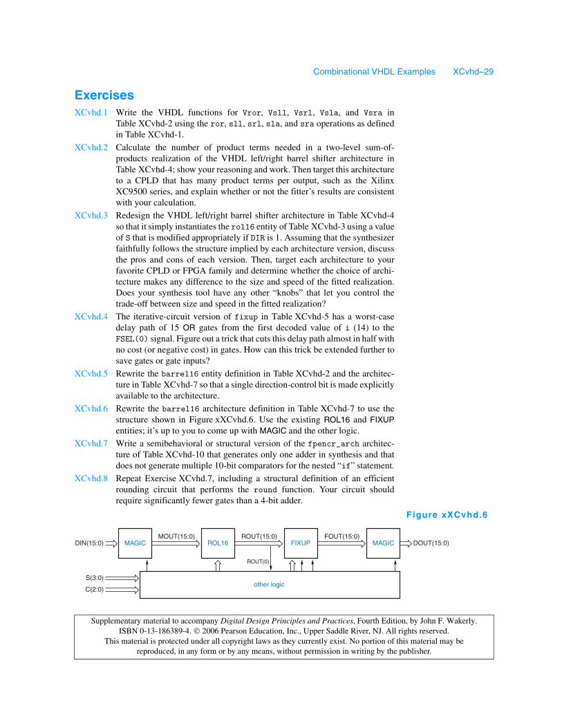
XCvhd.6 Rewrite the barrel16 architecture definition in Table XCvhd-7 to use thestructure shown in Figure xXCvhd.6. Use the existing ROL16 and FIXUPentities; it’s up to you to come up with MAGIC and the other logic.
XCvhd.7 Write a semibehavioral or structural version of the fpencr_arch architec-ture of Table XCvhd-10 that generates only one adder in synthesis and thatdoes not generate multiple 10-bit comparators for the nested “if” statement.
XCvhd.8 Repeat Exercise XCvhd.7, including a structural definition of an efficientrounding circuit that performs the round function. Your circuit shouldrequire significantly fewer gates than a 4-bit adder.
ROUT(15:0) FOUT(15:0)DOUT(15:0)ROL16
ROUT(0)
DIN(15:0)
S(3:0)
C(2:0)
MAGICMOUT(15:0)
other logic
MAGICFIXUP
Figure xXCvhd.6

Combinational VHDL Examples XCvhd–30
Supplementary material to accompany Digital Design Principles and Practices, Fourth Edition, by John F. Wakerly. ISBN 0-13-186389-4. 2006 Pearson Education, Inc., Upper Saddle River, NJ. All rights reserved.
This material is protected under all copyright laws as they currently exist. No portion of this material may be reproduced, in any form or by any means, without permission in writing by the publisher.
XCvhd.9 Redesign the VHDL dual-priority encoder of Section XCvhd.3 to get better,known performance, as suggested in the last paragraph of the section.
XCvhd.10 Write a structural VHDL architecture for a 64-bit comparator that is similarto Table XCvhd-15 except that it builds up the comparison result seriallyfrom least to most significant stage.
XCvhd.11 Write a VHDL test bench that checks for correct results from the comp64architecture of Table XCvhd-13 for a hundred thousand random pairs of 64-bit inputs. The pairs can’t be completely random or you’ll almost never checkthe EQ output. Then use the same test bench to instantiate and test thecomp64s architecture of Table XCvhd-15.
XCvhd.12 What significant change occurs in the synthesis of the VHDL program inTable XCvhd-17 if we change the statements in the “when others” case to“null”?
XCvhd.13 Write a VHDL test bench that checks for correct results from the Vmodecmparchitecture in Table XCvhd-17 for a hundred thousand random pairs of 32-bit inputs in each of its three modes. The pairs can’t be completely randomor you’ll almost never check the EQ output. Then use the same test bench toinstantiate and test the Vmodecpe architecture in Table XCvhd-18.
XCvhd.14 Target both mode-dependent comparator architectures, in Tables XCvhd-17and XCvhd-18, to a your favorite CPLD or FPGA family using a synthesistool and fitter. Compare the speed and the resource requirements of the twofitted realizations. Does your synthesis tool have any “knobs” that let youcontrol the trade-off between size and speed in the fitted realizations, and ifso, do these knobs affect which architecture can yield the smallest or fastestrealization?
XCvhd.15 Write behavioral VHDL programs for the “ADDERx” components used inTable XCvhd-20.
XCvhd.16 Write a structural VHDL programs for the “ADDERx” components inTable XCvhd-20. Use a generic definition so that the same entity can beinstantiated for ADDER2, ADDER3, and ADDER4, and show what changesmust be made in Table XCvhd-20 to do this.
XCvhd.17 Write a structural VHDL program for the “INCR5” component inTable XCvhd-20.
XCvhd.18 Using an available VHDL synthesis tool, synthesize the Tic-Tac-Toe designof Section XCvhd.7, fit it into an available FPGA, and determine how manyinternal resources it uses. Then try to reduce the resource requirements byspecifying a different encoding of the moves in the TTTdefs package.
XCvhd.19 The Tic-Tac-Toe program in Section XCvhd.7 eventually loses against anintelligent opponent if applied to the grid state shown in Figure xXCvhd.19.Use an available VHDL simulator to prove that this is true. Then modify thePICK entity to win in this and similar situations and verify your design usingthe simulator.
X
Y
Y
Figure xXCvhd.19