Combinational circuit
35
-
Upload
shailendra-gohil -
Category
Education
-
view
120 -
download
5
Transcript of Combinational circuit
DECODER
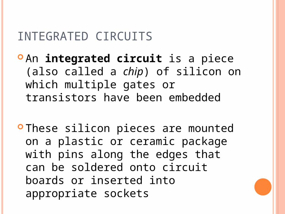
INTEGRATED CIRCUITS
An integrated circuit is a piece (also called a chip) of silicon on which multiple gates or transistors have been embedded
These silicon pieces are mounted on a plastic or ceramic package with pins along the edges that can be soldered onto circuit boards or inserted into appropriate sockets
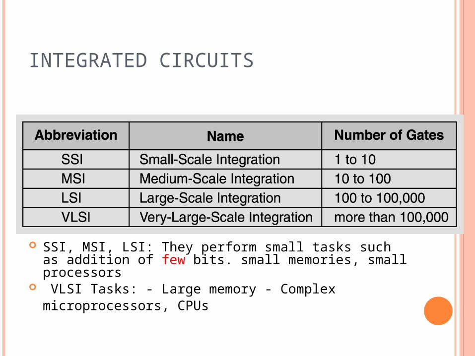
INTEGRATED CIRCUITS
SSI, MSI, LSI: They perform small tasks such as addition of few bits. small memories, small processors
VLSI Tasks: - Large memory - Complex microprocessors, CPUs
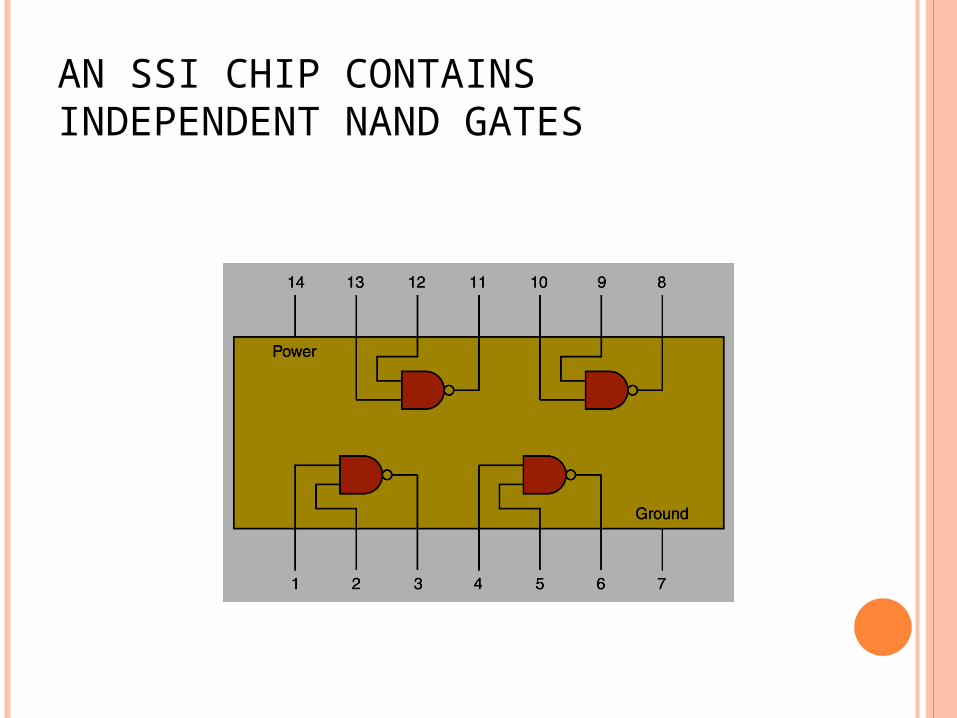
AN SSI CHIP CONTAINS INDEPENDENT NAND GATES
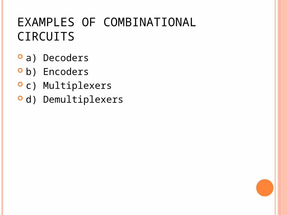
EXAMPLES OF COMBINATIONAL CIRCUITS
a) Decoders b) Encoders c) Multiplexers d) Demultiplexers
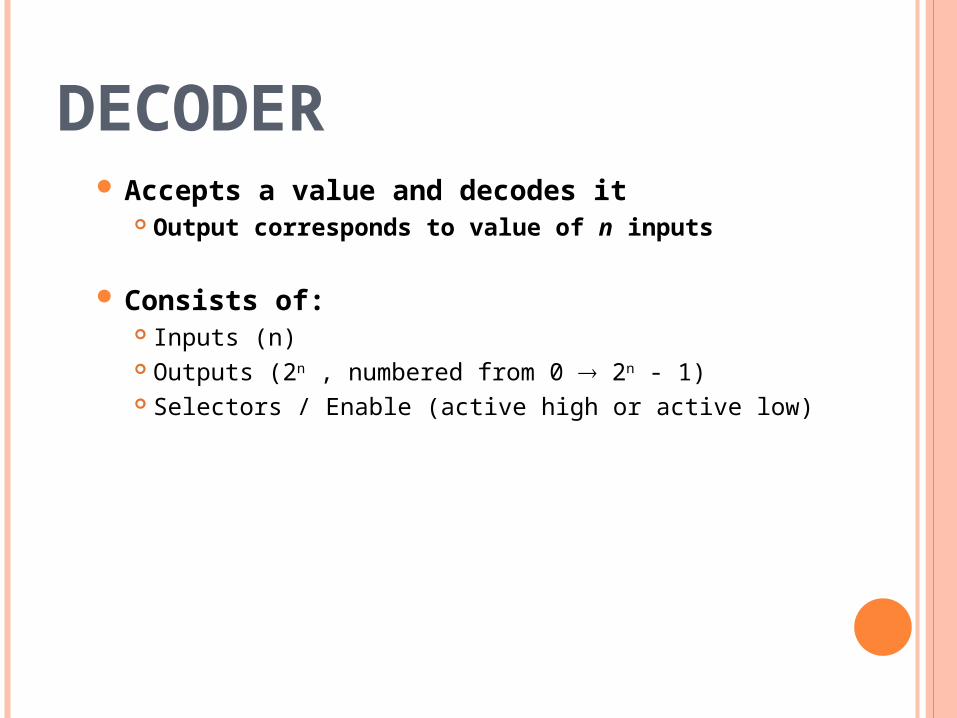
DECODER Accepts a value and decodes it
Output corresponds to value of n inputs
Consists of: Inputs (n) Outputs (2n , numbered from 0 2n - 1) Selectors / Enable (active high or active low)
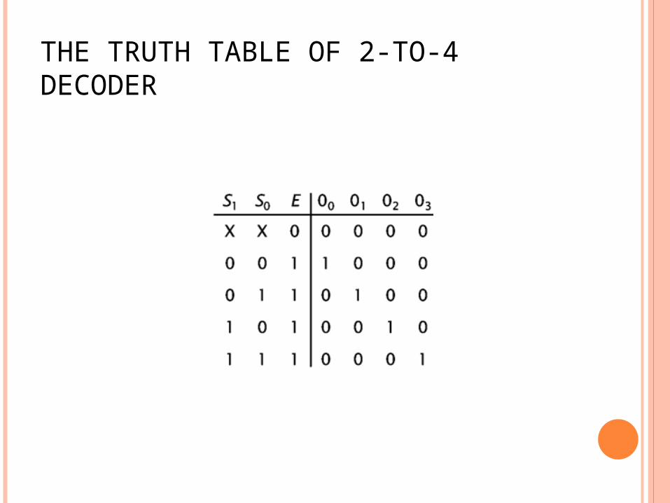
THE TRUTH TABLE OF 2-TO-4 DECODER
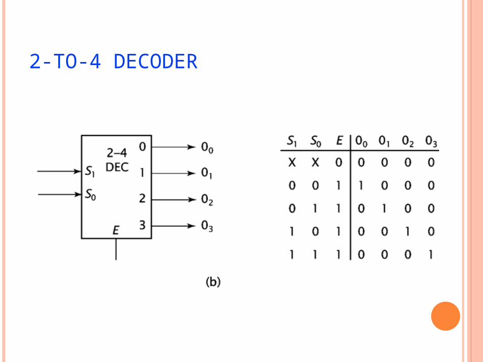
2-TO-4 DECODER
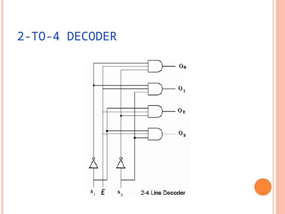
2-TO-4 DECODER
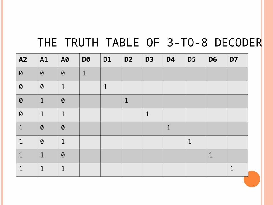
THE TRUTH TABLE OF 3-TO-8 DECODERA2 A1 A0 D0 D1 D2 D3 D4 D5 D6 D7
0 0 0 1
0 0 1 1
0 1 0 1
0 1 1 1
1 0 0 1
1 0 1 1
1 1 0 1
1 1 1 1
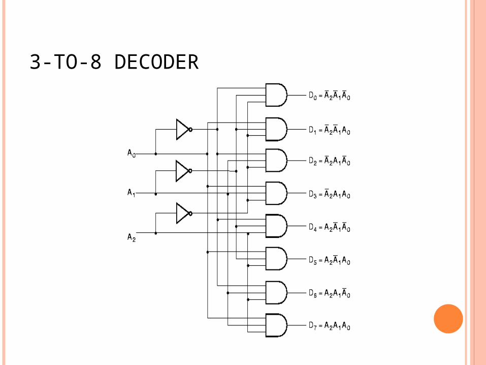
3-TO-8 DECODER
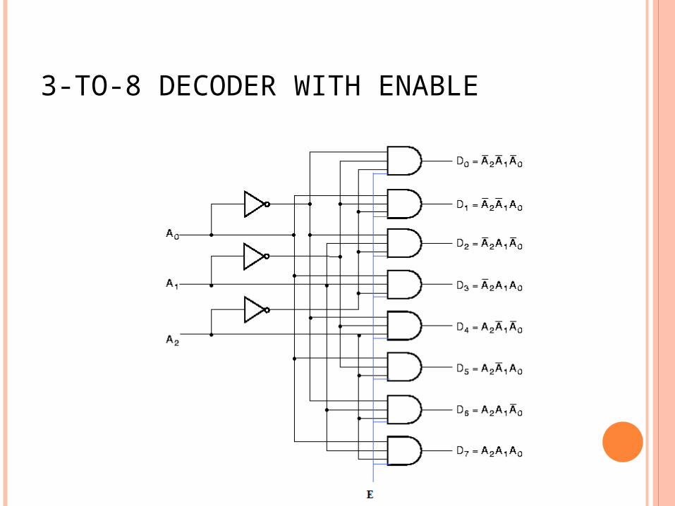
3-TO-8 DECODER WITH ENABLE
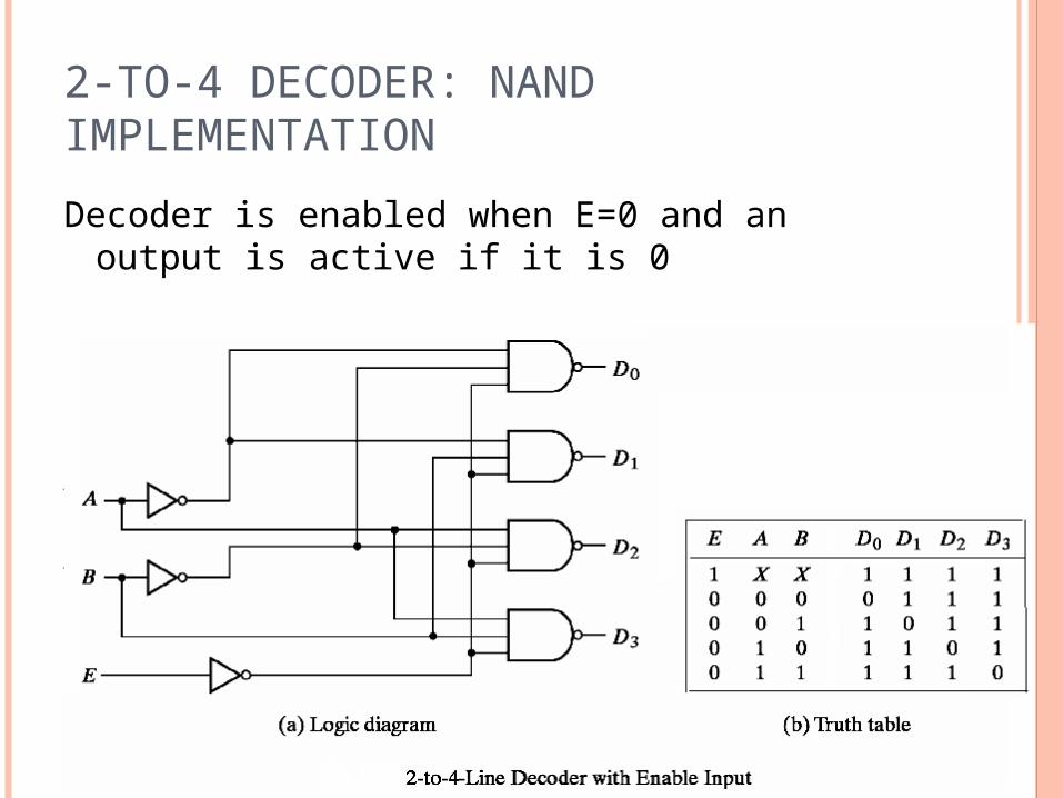
2-TO-4 DECODER: NAND IMPLEMENTATION
Decoder is enabled when E=0 and an output is active if it is 0
DECODER EXPANSION Decoder expansion
Combine two or more small decoders with enable inputs to form a larger decoder
3-to-8-line decoder constructed from two 2-to-4-line decoders The MSB is connected to the enable inputs if A2=0, upper is enabled; if A2=1, lower is enabled.
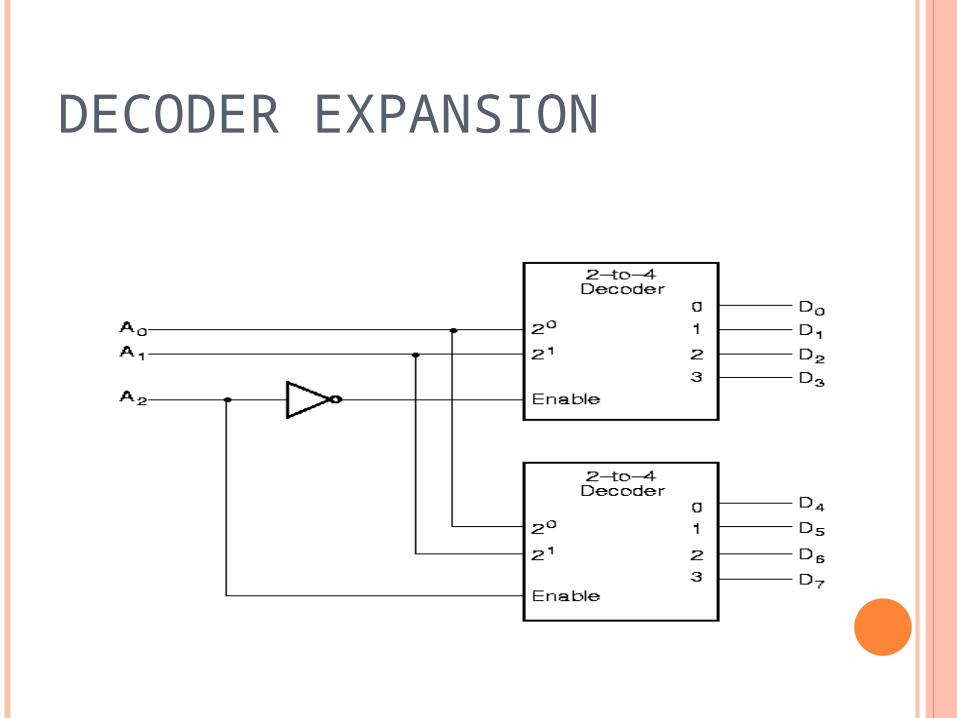
DECODER EXPANSION
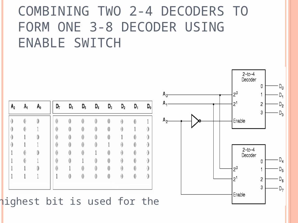
COMBINING TWO 2-4 DECODERS TO FORM ONE 3-8 DECODER USING ENABLE SWITCH
The highest bit is used for the enables

ENCODER
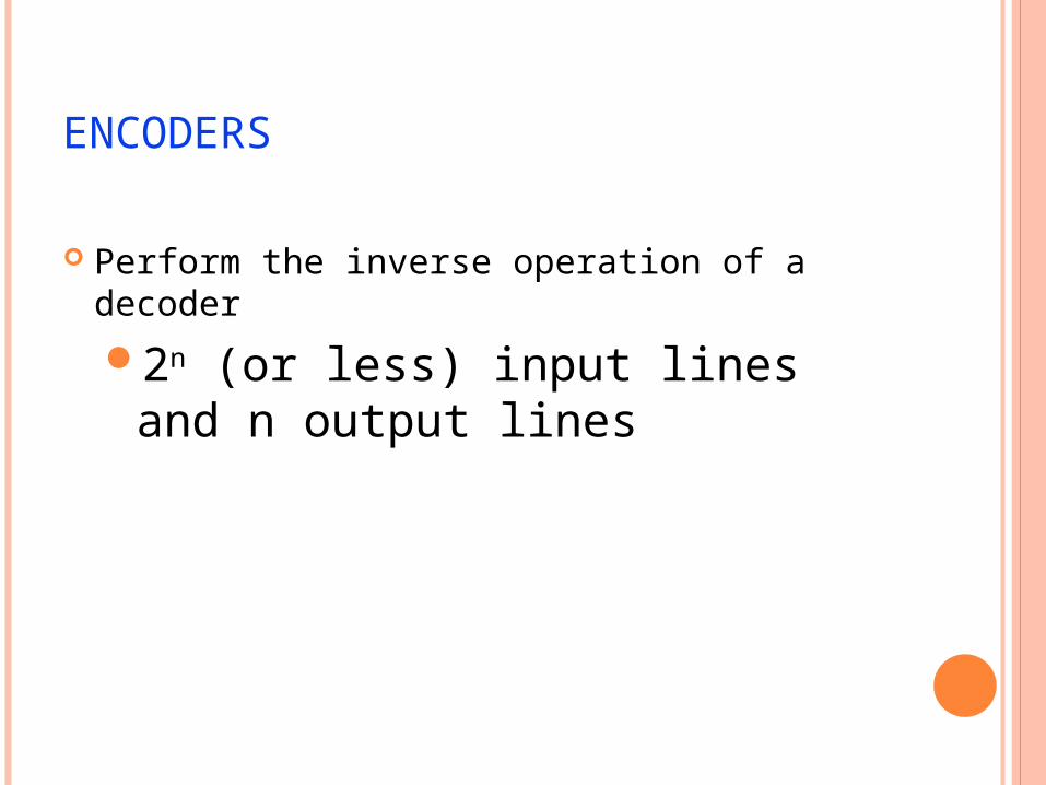
ENCODERS
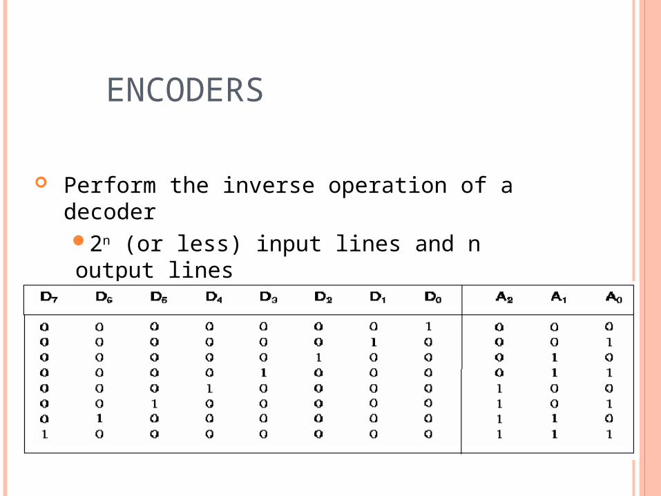
Perform the inverse operation of a decoder
2n (or less) input lines and n output lines
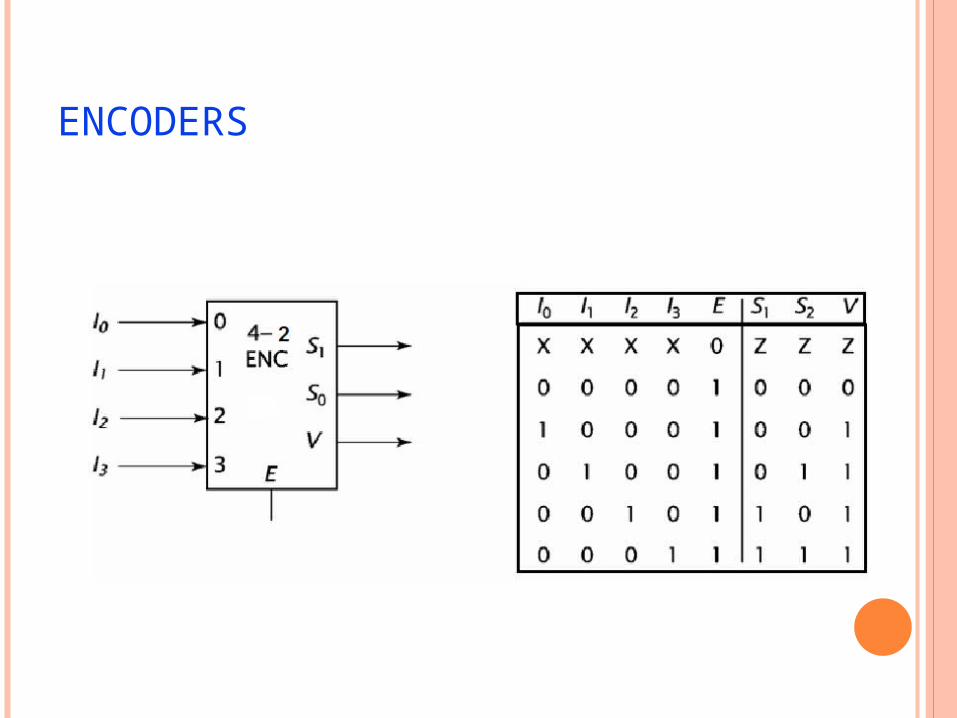
ENCODERS
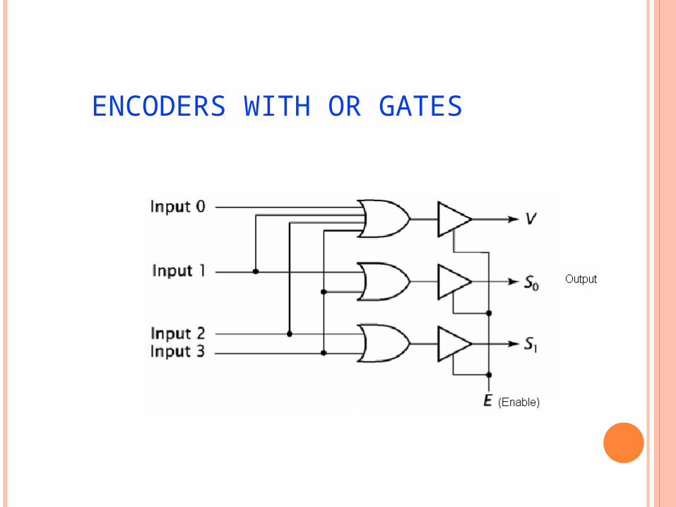
ENCODERS WITH OR GATES
ENCODERS
Perform the inverse operation of a decoder2n (or less) input lines and n output lines
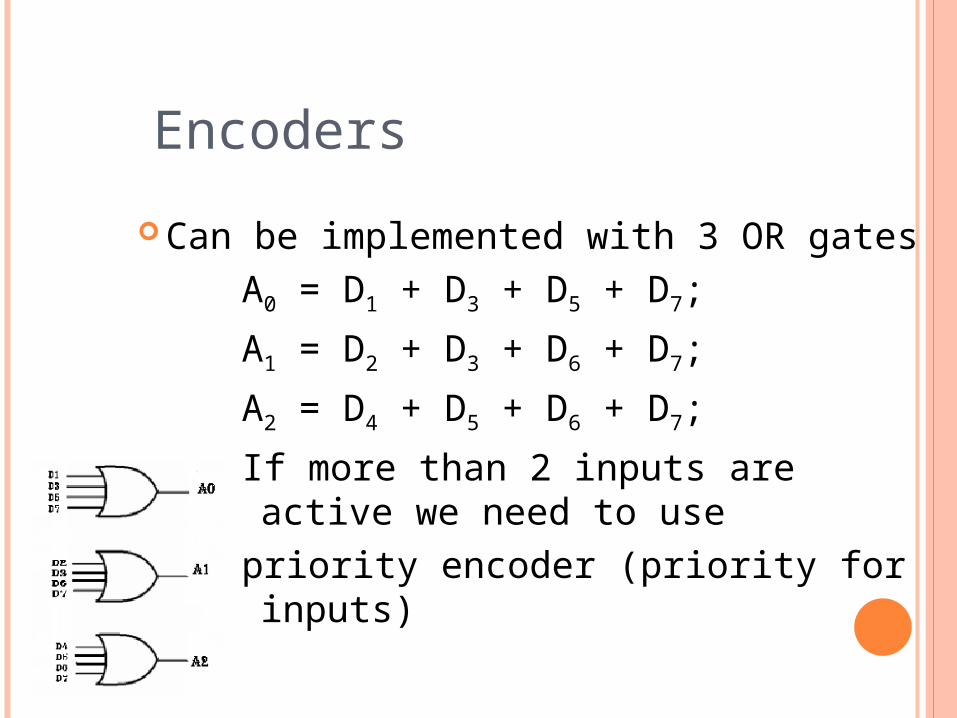
Can be implemented with 3 OR gatesA0 = D1 + D3 + D5 + D7;
A1 = D2 + D3 + D6 + D7;
A2 = D4 + D5 + D6 + D7;
If more than 2 inputs are active we need to use
priority encoder (priority for inputs)
Encoders
MULTIPLEXER (MUX)
A selector chooses a single data input and passes it to the MUX output
It has one output selected at a time.
A multiplexer can use addressing bits to select one of several input bits to be the output.
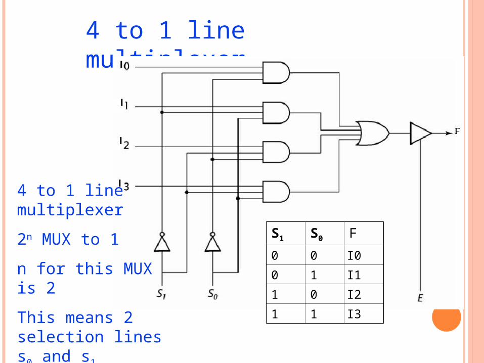
4 to 1 line multiplexer
S1 S0 F
0 0 I0
0 1 I1
1 0 I2
1 1 I3
4 to 1 line multiplexer
2n MUX to 1
n for this MUX is 2
This means 2 selection lines s0 and s1
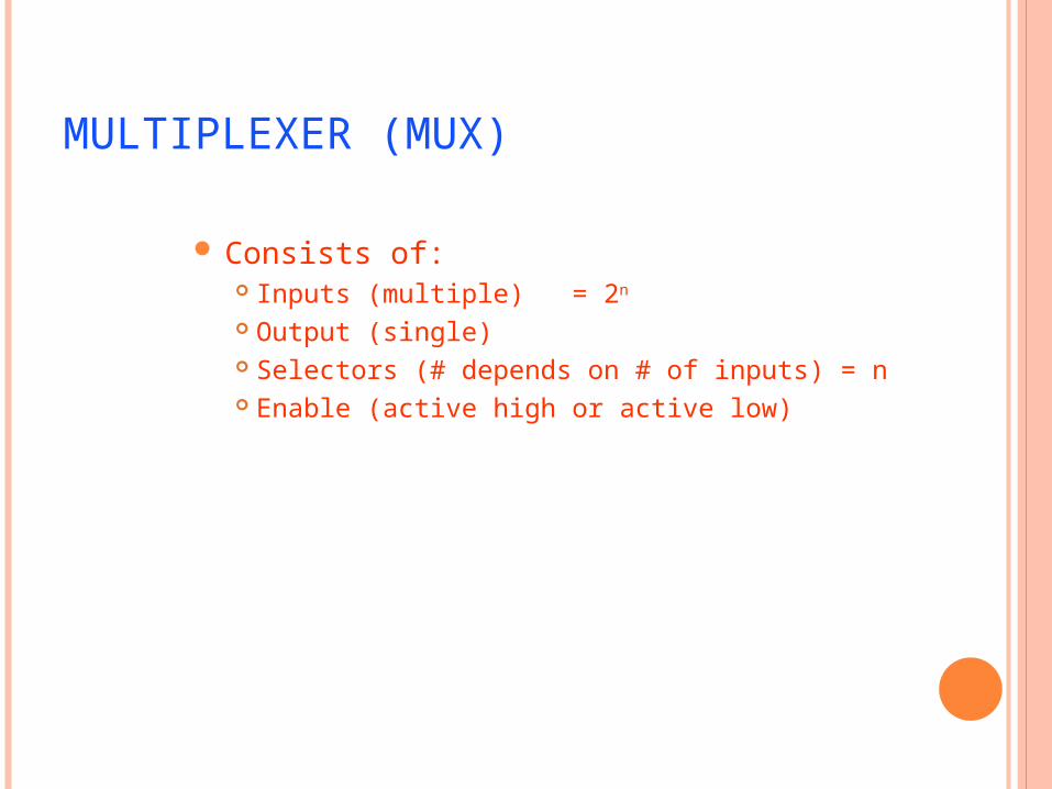
MULTIPLEXER (MUX)
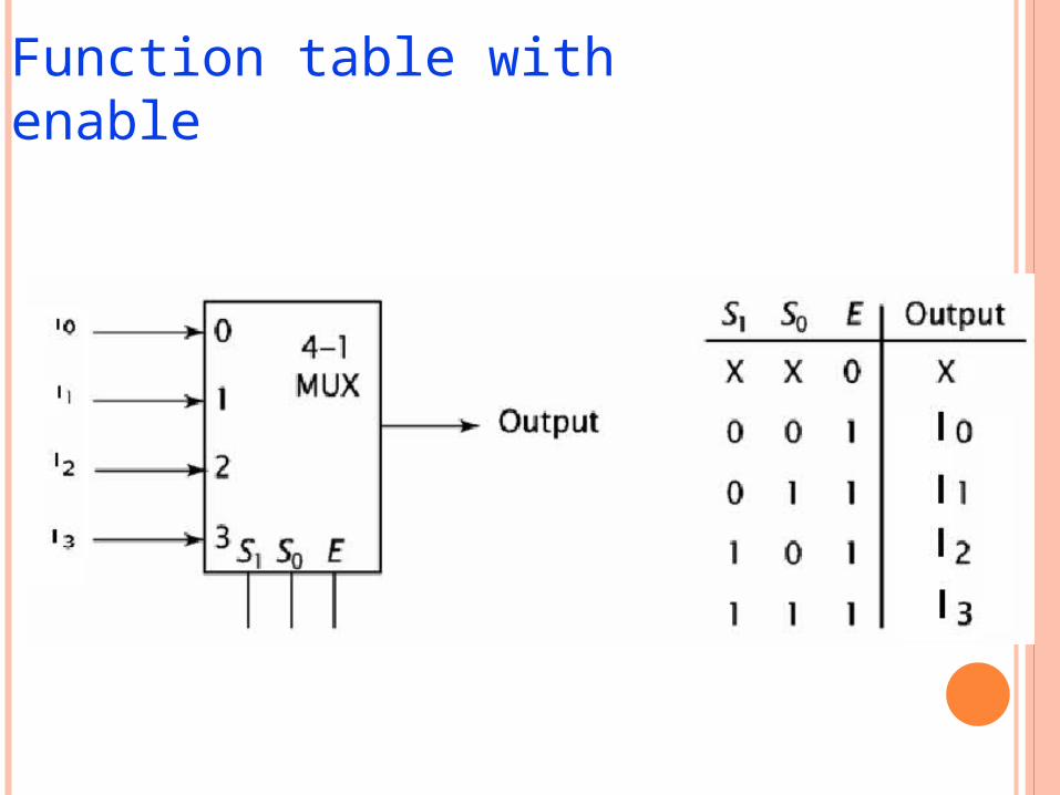
Consists of: Inputs (multiple) = 2n
Output (single) Selectors (# depends on # of inputs) = n Enable (active high or active low)
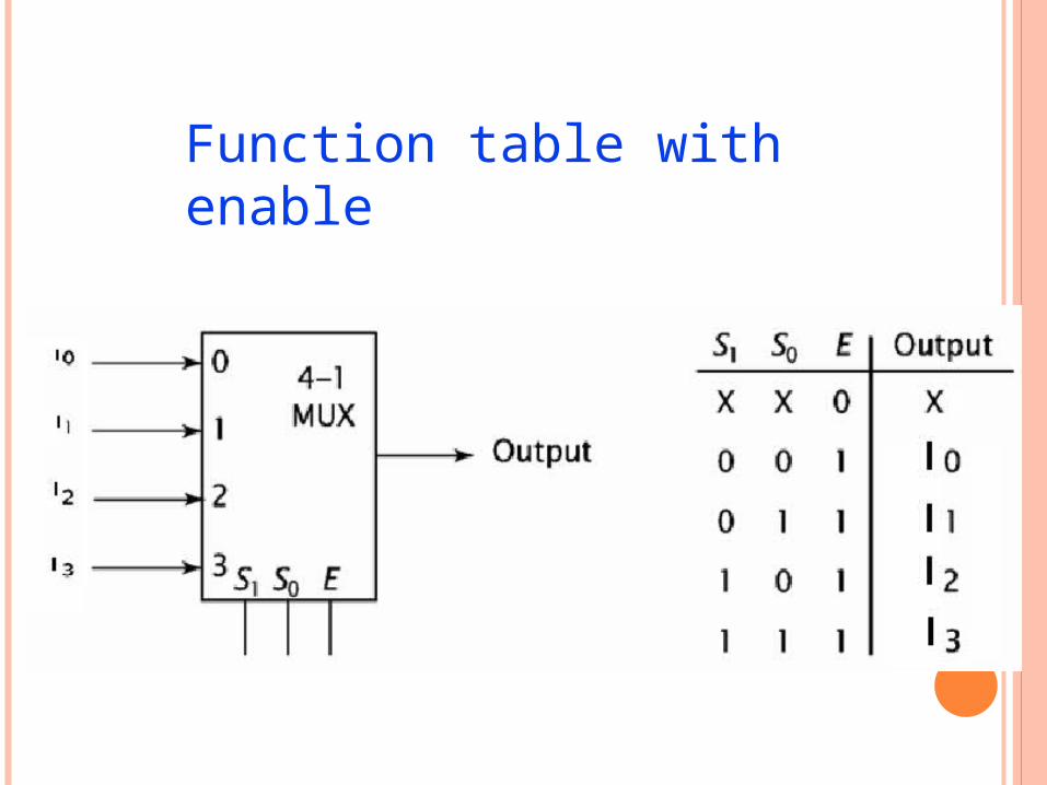
Function table with enable
MULTIPLEXERS VERSUS DECODERS
• A Multiplexer uses n binary select bits to choose from a maximum of 2n unique input lines.•Multiplexers and decoders both can decode minterms.•Decoders have n number of output lines while multiplexers have only one output line.•The decoded minterms are used to select data from one of up to 2n unique data input lines. •The output of the multiplexer is the data input whose index is specified by the n bit code.
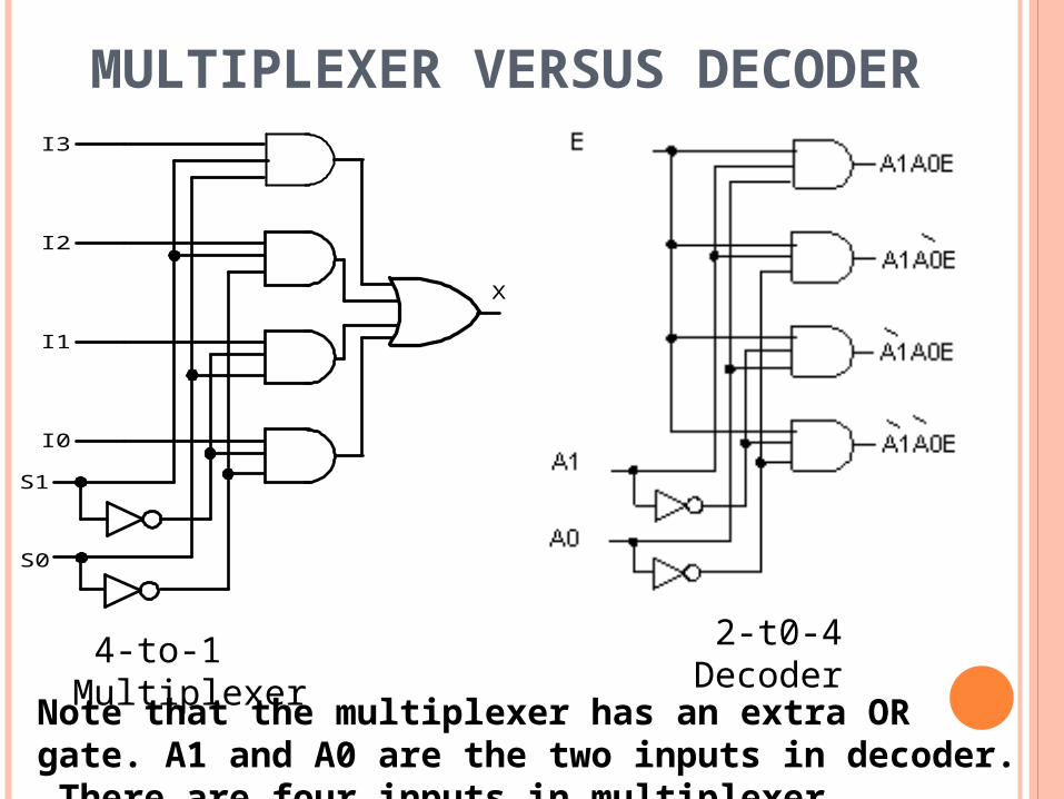
MULTIPLEXER VERSUS DECODER
S0
S1
I3
I2
I1
I0
X
Note that the multiplexer has an extra OR gate. A1 and A0 are the two inputs in decoder. There are four inputs in multiplexer.
4-to-1 Multiplexer 2-t0-4 Decoder
Function table with enable
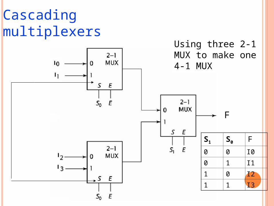
Cascading multiplexers
Using three 2-1 MUX to make one 4-1 MUX
S1 S0 F
0 0 I0
0 1 I1
1 0 I2
1 1 I3
F
F2-1
MUX
S E
S2 E
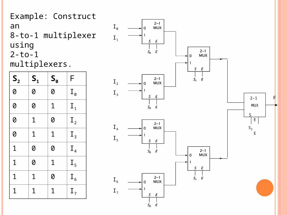
S2 S1 S0 F
0 0 0 I0
0 0 1 I1
0 1 0 I2
0 1 1 I3
1 0 0 I4
1 0 1 I5
1 1 0 I6
1 1 1 I7
I0
I1
I2
I3
I4
I5
I6
I7
Example: Construct an 8-to-1 multiplexer using 2-to-1 multiplexers.
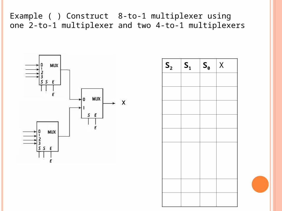
Example ( ) Construct 8-to-1 multiplexer using one 2-to-1 multiplexer and two 4-to-1 multiplexers
S2 S1 S0 X
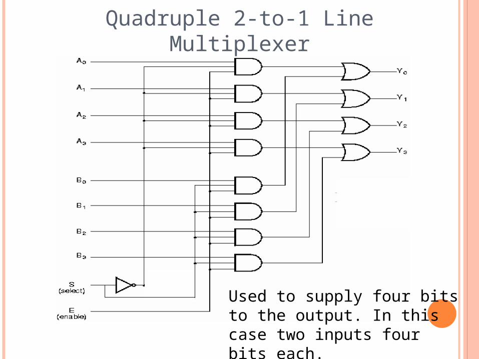
Quadruple 2-to-1 Line Multiplexer
Used to supply four bits to the output. In this case two inputs four bits each.
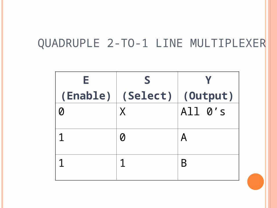
QUADRUPLE 2-TO-1 LINE MULTIPLEXER
E(Enable)
S(Select)
Y(Output)
0 X All 0’s
1 0 A
1 1 B