1 Chapter 1 Foundation Computer Networks: A Systems Approach, 5e Larry L. Peterson and Bruce S....
38
1 Chapter 1 Foundation Computer Networks: A Systems Approach, 5 Larry L. Peterson and Bruce S. Davie Copyright © 2010, Elsevier Inc. All rights Reserved
-
Upload
lee-holmes -
Category
Documents
-
view
226 -
download
2
Transcript of 1 Chapter 1 Foundation Computer Networks: A Systems Approach, 5e Larry L. Peterson and Bruce S....

1
Chapter 1
Foundation
Computer Networks: A Systems Approach, 5eLarry L. Peterson and Bruce S. Davie
Copyright © 2010, Elsevier Inc. All rights Reserved

2
Chapter 1
Problems
How to build a scalable network that will support different applications?
What is a computer network? How is a computer network different from other
types of networks? What is a computer network architecture?

3
Chapter 1
Chapter Outline
Applications Requirements Network Architecture Performance

4
Chapter 1
Chapter Goal
Exploring the requirements that different applications and different communities place on the computer network
Introducing the idea of network architecture Define key metrics that will be used to evaluate
the performance of computer network

5
Chapter 1
Applications
Most people know about the Internet (a computer network) through applications World Wide Web Email Online Social Network Streaming Audio Video File Sharing Instant Messaging …

6
Chapter 1
Example of an application
A multimedia application including video-conferencing

7
Chapter 1
Application Protocol URL
Uniform resource locater http://www.cs.princeton.edu/~llp/index.html
HTTP Hyper Text Transfer Protocol
TCP Transmission Control Protocol
17 messages for one URL request 6 to find the IP (Internet Protocol) address 3 for connection establishment of TCP 4 for HTTP request and acknowledgement
Request: I got your request and I will send the data Reply: Here is the data you requested; I got the data
4 messages for tearing down TCP connection

8
Chapter 1
Requirements
Application Programmer List the services that his application needs: delay
bounded delivery of data Network Designer
Design a cost-effective network with sharable resources
Network Provider List the characteristics of a system that is easy to
manage

9
Chapter 1
Connectivity Need to understand the
following terminologies Scale Link Nodes Point-to-point Multiple access Switched Network
Circuit Switched Packet Switched
Packet, message Store-and-forward
(a) Point-to-point
(b) Multiple access

10
Chapter 1
Connectivity Terminologies (contd.)
Cloud Hosts Switches internetwork Router/gateway Host-to-host connectivity Address Routing Unicast/broadcast/multicast
(a) A switched network
(b) Interconnection of networks
(a)
(b)

11
Chapter 1
Cost-Effective Resource Sharing Resource: links and
nodes How to share a link?
Multiplexing De-multiplexing Synchronous Time-division
Multiplexing Time slots/data
transmitted in predetermined slots
Multiplexing multiple logical flows over a single physical link

12
Chapter 1
Cost-Effective Resource Sharing FDM: Frequency Division
Multiplexing Statistical Multiplexing
Data is transmitted based on demand of each flow.
What is a flow? Packets vs. Messages FIFO, Round-Robin,
Priorities (Quality-of-Service (QoS))
Congested? LAN, MAN, WAN SAN (System Area
Networks
A switch multiplexing packets from multiple sources onto one shared link

13
Chapter 1
Support for Common Services
Logical Channels Application-to-Application communication path or a
pipe
Process communicating over an abstract channel

14
Chapter 1
Common Communication Patterns
Client/Server Two types of communication channel
Request/Reply Channels Message Stream Channels

15
Chapter 1
Reliability
Network should hide the errors Bits are lost
Bit errors (1 to a 0, and vice versa) Burst errors – several consecutive errors
Packets are lost (Congestion) Links and Node failures Messages are delayed Messages are delivered out-of-order Third parties eavesdrop

16
Chapter 1
Network Architecture
Example of a layered network system

17
Chapter 1
Network Architecture
Layered system with alternative abstractions available at a given layer

18
Chapter 1
Protocols
Protocol defines the interfaces between the layers in the same system and with the layers of peer system
Building blocks of a network architecture Each protocol object has two different interfaces
service interface: operations on this protocol peer-to-peer interface: messages exchanged with
peer Term “protocol” is overloaded
specification of peer-to-peer interface module that implements this interface

19
Chapter 1
Interfaces
Service and Peer Interfaces

20
Chapter 1
Protocols
Protocol Specification: prose, pseudo-code, state transition diagram
Interoperable: when two or more protocols that implement the specification accurately
IETF: Internet Engineering Task Force

21
Chapter 1
Protocol Graph
Example of a protocol graph
nodes are the protocols and links the “depends-on” relation

22
Chapter 1
Encapsulation
High-level messages are encapsulated inside of low-level messages

23
Chapter 1
OSI Architecture
The OSI 7-layer Model
OSI – Open Systems Interconnection

24
Chapter 1
Description of Layers
Physical Layer Handles the transmission of raw bits over a communication link
Data Link Layer Collects a stream of bits into a larger aggregate called a frame Network adaptor along with device driver in OS implement the
protocol in this layer Frames are actually delivered to hosts
Network Layer Handles routing among nodes within a packet-switched network Unit of data exchanged between nodes in this layer is called a
packet
The lower three layers are implemented on all network nodes

25
Chapter 1
Description of Layers
Transport Layer Implements a process-to-process channel Unit of data exchanges in this layer is called a message
Session Layer Provides a name space that is used to tie together the potentially
different transport streams that are part of a single application Presentation Layer
Concerned about the format of data exchanged between peers Application Layer
Standardize common type of exchanges
The transport layer and the higher layers typically run only on end-hosts and not on the intermediate switches and routers

26
Chapter 1
Internet Architecture
Internet Protocol Graph
Alternative view of the Internet architecture. The “Network” layer shown here is sometimes referred to as the “sub-network” or “link” layer.

27
Chapter 1
Internet Architecture
Defined by IETF Three main features
Does not imply strict layering. The application is free to bypass the defined transport layers and to directly use IP or other underlying networks
An hour-glass shape – wide at the top, narrow in the middle and wide at the bottom. IP serves as the focal point for the architecture
In order for a new protocol to be officially included in the architecture, there needs to be both a protocol specification and at least one (and preferably two) representative implementations of the specification

28
Chapter 1
Application Programming Interface
Interface exported by the network Since most network protocols are implemented (those in
the high protocol stack) in software and nearly all computer systems implement their network protocols as part of the operating system, when we refer to the interface “exported by the network”, we are generally referring to the interface that the OS provides to its networking subsystem
The interface is called the network Application Programming Interface (API)

29
Chapter 1
Application Programming Interface (Sockets)
Socket Interface was originally provided by the Berkeley distribution of Unix- Now supported in virtually all operating systems
Each protocol provides a certain set of services, and the API provides a syntax by which those services can be invoked in this particular OS

30
Chapter 1
Performance
Bandwidth Width of the frequency band Number of bits per second that can be transmitted over a
communication link 1 Mbps: 1 x 106 bits/second = 1x220 bits/sec 1 x 10⁻⁶ seconds to transmit each bit or imagine that a
timeline, now each bit occupies 1 micro second space. On a 2 Mbps link the width is 0.5 micro second. Smaller the width more will be transmission per unit time.
31
Chapter 1
Bandwidth
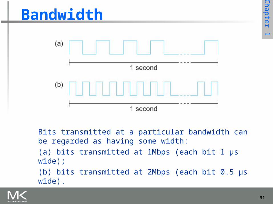
Bits transmitted at a particular bandwidth can be regarded as having some width:
(a) bits transmitted at 1Mbps (each bit 1 μs wide);
(b) bits transmitted at 2Mbps (each bit 0.5 μs wide).
32
Chapter 1
Performance
Latency = Propagation + transmit + queue Propagation = distance/speed of light Transmit = size/bandwidth
One bit transmission => propagation is important Large bytes transmission => bandwidth is important

33
Chapter 1
Delay X Bandwidth
We think the channel between a pair of processes as a hollow pipe
Latency (delay) length of the pipe and bandwidth the width of the pipe
Delay of 50 ms and bandwidth of 45 Mbps 50 x 10-3 seconds x 45 x 106 bits/second 2.25 x 106 bits = 280 KB data.
Network as a pipe

34
Chapter 1
Delay X Bandwidth
Relative importance of bandwidth and latency depends on application For large file transfer, bandwidth is critical For small messages (HTTP, NFS, etc.), latency is
critical Variance in latency (jitter) can also affect some
applications (e.g., audio/video conferencing)

35
Chapter 1
Delay X Bandwidth
How many bits the sender must transmit before the first bit arrives at the receiver if the sender keeps the pipe full
Takes another one-way latency to receive a response from the receiver
If the sender does not fill the pipe—send a whole delay × bandwidth product’s worth of data before it stops to wait for a signal—the sender will not fully utilize the network

36
Chapter 1
Delay X Bandwidth
Infinite bandwidth RTT dominates Throughput = TransferSize / TransferTime TransferTime = RTT + 1/Bandwidth x
TransferSize Its all relative
1-MB file to 1-Gbps link looks like a 1-KB packet to 1-Mbps link

37
Chapter 1
Relationship between bandwidth and latency
A 1-MB file would fill the 1-Mbps link 80 times,
but only fill the 1-Gbps link 1/12 of one time

38
Chapter 1
Summary
We have identified what we expect from a computer network
We have defined a layered architecture for computer network that will serve as a blueprint for our design
We have discussed two performance metrics using which we can analyze the performance of computer networks