


Languages
Pages
Legal

VICTRIX 90VICTRIX 115
Wall-hung condensing boilersfor high power
VICTRIX 90 - 115
2
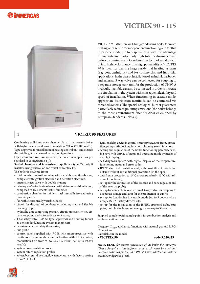
1 VICTRIX 90 FEATURES
VICTRIX 90 is the new wall-hung condensing boiler for room heating only, set-up for independent functioning and for that in cascade mode (up to 3 appliances), with the advantage of guaranteeing particularly high total performance and reduced running costs. Condensation technology allows to obtain high performance. Th e high potentiality of VICTRIX 90 is ideal for heating large residential heating systems (e.g. condominiums) and for commercial and industrial applications. In the case of installation of an individual boiler, and external 3-way valve can be connected for coupling to a separate storage tank unit for the production of DHW. A hydraulic manifold can also be connected in order to increase the circulation in the system with consequent fl exibility and speed of installation. When functioning in cascade mode, appropriate distribution manifolds can be connected via threaded systems. Th e special ecological burner guarantees particularly reduced polluting emissions (the boiler belongs to the most environment-friendly class envisioned by European Standards - class 5).
Condensing wall-hung open chamber fan assisted premix boiler with high effi ciency and forced circulation, 90kW (77,400 kcal/h).Type-approved for installation in heating control unit and outside the building, it can be used in two confi gurations:Open chamber and fan assisted (the boiler is supplied as per standard in confi guration B23);Sealed chamber and fan-assisted (appliance type C), only if installed using vertical or horizontal concentric kits.Th e boiler is made up from:• total premix combustion system with metalfi bre multigas burner,
complete with ignition electrode and detection electrode;• pneumatic gas valve with double shutter;• primary gas/water heat exchanger with stainless steel double coil,
composed of 16 elements (10+6 fl ue side);• combustion chamber in stainless steel internally isolated using
ceramic panels;• fan with electronically variable speed;• circuit for disposal of condensate including trap and fl exible
discharge pipe;• hydraulic unit comprising primary circuit pressure switch, cir-
culation pump and automatic air vent valve;• 4 bar safety valve (ISPESL type-approved) and draining funnel
as per standard, heating system manometer;• over-temperature safety thermostat;• fl ue probe;• control panel supplied with P.C.B. with microprocessor with
continuous fl ame modulation on heating with P.I.D. control, modulation fi eld from 90 to 22.5 kW (from 77,400 to 19,350 kcal/h);
• system fl ow regulation probe;• system return regulation probe;• adjustable central heating fl ow temperature with factory setting
from 25 to 85°C;
• ignition delay device in central heating phase, anti-freeze protec-tion, pump anti-blocking function, chimney sweep function;
• setting and regulation of the boiler functioning parameters us-ing keys with display of status and operating mode by means of a 4-digit display;
• self-diagnosis system with digital display of the temperature, functioning status and error codes;
• IPX5D electrical insulation level, with possibility of installation outside without any additional protection (in the open);
• anti-freeze protection to -5 °C as per standard (-15 °C with rel-evant kit optional);
• set-up for the connection of the cascade and zone regulator and of the external probe;
• set-up for connection to an external 3-way valve, for coupling to a separate storage tank unit for the production of DHW;
• set-up for functioning in cascade mode (up to 3 boilers with a unique ISPESL safety devices kit);
• set-up for the installation of the ISPESL-approved safety stub pipes, both in single and set confi guration (up to 3 boilers).
Supplied complete with sample points for combustion analysis and gas interception cocks.
Category II 2H3P appliance, functions with natural gas and L.P.G. CE marking.is available in the model:• VICTRIX 90 code 3.020425
NOTA BENE: for correct installation of the boiler the Immergas "Green Range" air intake/fumes exhaust kit must be used and however, dedicated for the VICTRIX 90 boiler, whether in single or cascade confi guration (set).
VICTRIX 90 - 115
3
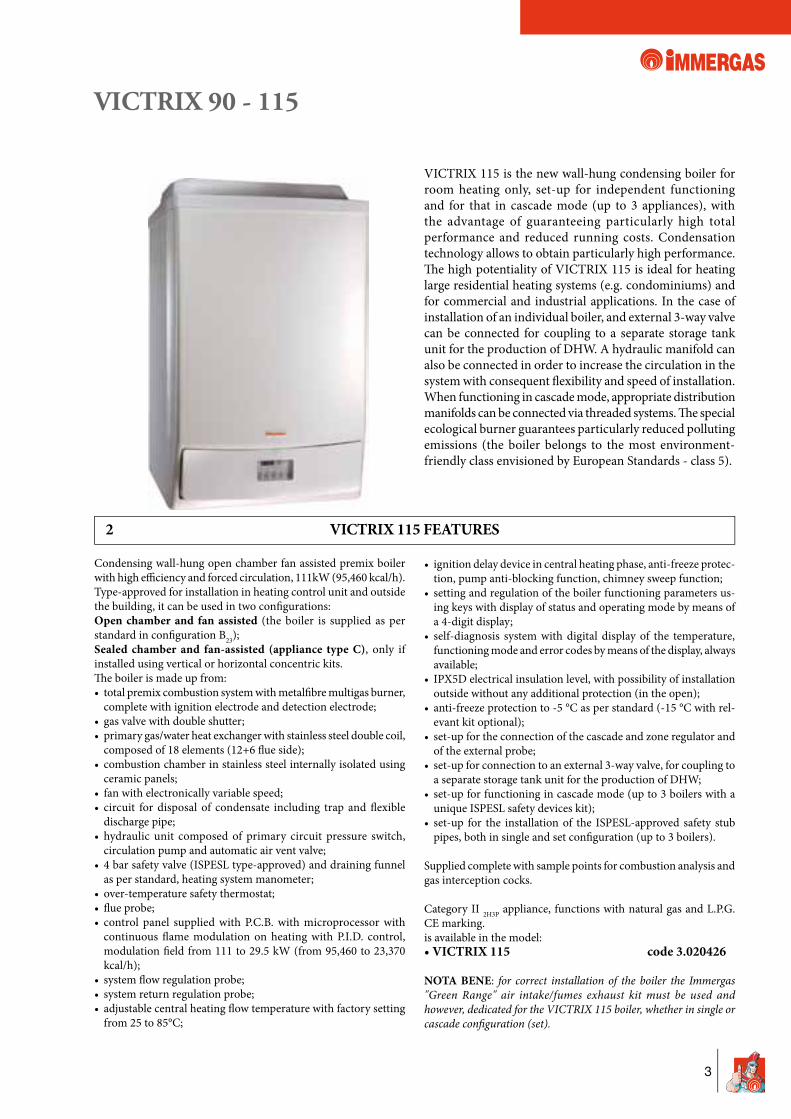
2 VICTRIX 115 FEATURES
VICTRIX 115 is the new wall-hung condensing boiler for room heating only, set-up for independent functioning and for that in cascade mode (up to 3 appliances), with the advantage of guaranteeing particularly high total performance and reduced running costs. Condensation technology allows to obtain particularly high performance. Th e high potentiality of VICTRIX 115 is ideal for heating large residential heating systems (e.g. condominiums) and for commercial and industrial applications. In the case of installation of an individual boiler, and external 3-way valve can be connected for coupling to a separate storage tank unit for the production of DHW. A hydraulic manifold can also be connected in order to increase the circulation in the system with consequent fl exibility and speed of installation. When functioning in cascade mode, appropriate distribution manifolds can be connected via threaded systems. Th e special ecological burner guarantees particularly reduced polluting emissions (the boiler belongs to the most environment-friendly class envisioned by European Standards - class 5).
Condensing wall-hung open chamber fan assisted premix boiler with high effi ciency and forced circulation, 111kW (95,460 kcal/h).Type-approved for installation in heating control unit and outside the building, it can be used in two confi gurations:Open chamber and fan assisted (the boiler is supplied as per standard in confi guration B23);Sealed chamber and fan-assisted (appliance type C), only if installed using vertical or horizontal concentric kits.Th e boiler is made up from:• total premix combustion system with metalfi bre multigas burner,
complete with ignition electrode and detection electrode;• gas valve with double shutter;• primary gas/water heat exchanger with stainless steel double coil,
composed of 18 elements (12+6 fl ue side);• combustion chamber in stainless steel internally isolated using
ceramic panels;• fan with electronically variable speed;• circuit for disposal of condensate including trap and fl exible
discharge pipe;• hydraulic unit composed of primary circuit pressure switch,
circulation pump and automatic air vent valve;• 4 bar safety valve (ISPESL type-approved) and draining funnel
as per standard, heating system manometer;• over-temperature safety thermostat;• fl ue probe;• control panel supplied with P.C.B. with microprocessor with
continuous fl ame modulation on heating with P.I.D. control, modulation fi eld from 111 to 29.5 kW (from 95,460 to 23,370 kcal/h);
• system fl ow regulation probe;• system return regulation probe;• adjustable central heating fl ow temperature with factory setting
from 25 to 85°C;
• ignition delay device in central heating phase, anti-freeze protec-tion, pump anti-blocking function, chimney sweep function;
• setting and regulation of the boiler functioning parameters us-ing keys with display of status and operating mode by means of a 4-digit display;
• self-diagnosis system with digital display of the temperature, functioning mode and error codes by means of the display, always available;
• IPX5D electrical insulation level, with possibility of installation outside without any additional protection (in the open);
• anti-freeze protection to -5 °C as per standard (-15 °C with rel-evant kit optional);
• set-up for the connection of the cascade and zone regulator and of the external probe;
• set-up for connection to an external 3-way valve, for coupling to a separate storage tank unit for the production of DHW;
• set-up for functioning in cascade mode (up to 3 boilers with a unique ISPESL safety devices kit);
• set-up for the installation of the ISPESL-approved safety stub pipes, both in single and set confi guration (up to 3 boilers).
Supplied complete with sample points for combustion analysis and gas interception cocks.
Category II 2H3P appliance, functions with natural gas and L.P.G. CE marking.is available in the model:• VICTRIX 115 code 3.020426
NOTA BENE: for correct installation of the boiler the Immergas "Green Range" air intake/fumes exhaust kit must be used and however, dedicated for the VICTRIX 115 boiler, whether in single or cascade confi guration (set).
VICTRIX 90 - 115
4
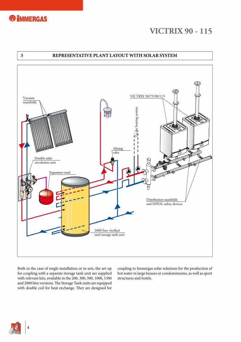
3 REPRESENTATIVE PLANT LAYOUT WITH SOLAR SYSTEM
Both in the case of single installation or in sets, the set-up for coupling with a separate storage tank unit are supplied with relevant kits, available in the 200, 300, 500, 1000, 1500 and 2000 litre versions. Th e Storage Tank units are equipped with double coil for heat exchange. Th ey are designed for
coupling to Immergas solar solutions for the production of hot water in large houses or condominiums, as well as sport structures and hotels.
Vacuummanifolds
Mixingvalve
VICTRIX 50/75/90/115
Double solarcirculation unit
Expansion vessel
To
the
heat
ing
syste
m
Distribution manifoldsand ISPESL safety devices
2000 litre vitri�edsteel storage tank unit
VICTRIX 90 - 115
5
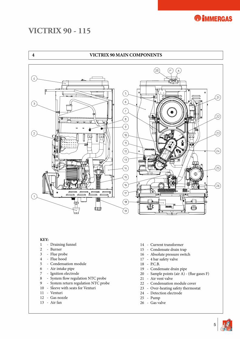
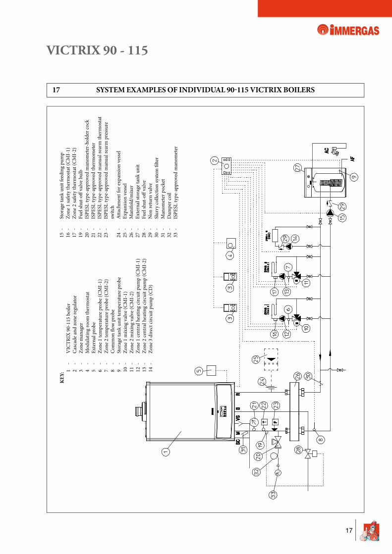
KEY: 1 - Draining funnel 2 - Burner 3 - Flue probe 4 - Flue hood 5 - Condensation module 6 - Air intake pipe 7 - Ignition electrode 8 - System fl ow regulation NTC probe 9 - System return regulation NTC probe 10 - Sleeve with seats for Venturi 11 - Venturi 12 - Gas nozzle 13 - Air fan
14 - Current transformer 15 - Condensate drain trap 16 - Absolute pressure switch 17 - 4 bar safety valve 18 - P.C.B. 19 - Condensate drain pipe 20 - Sample points (air A) - (fl ue gases F) 21 - Air vent valve 22 - Condensation module cover 23 - Over-heating safety thermostat 24 - Detection electrode 25 - Pump 26 - Gas valve
4 VICTRIX 90 MAIN COMPONENTS
VICTRIX 90 - 115
6
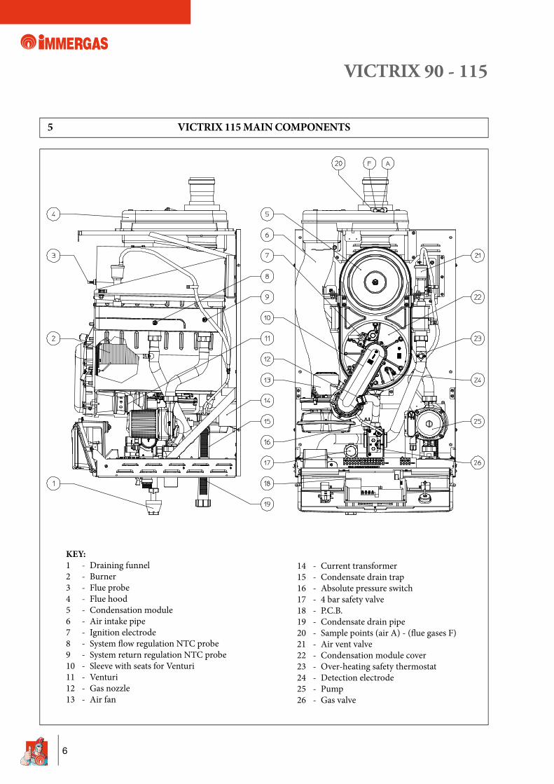
KEY: 1 - Draining funnel 2 - Burner 3 - Flue probe 4 - Flue hood 5 - Condensation module 6 - Air intake pipe 7 - Ignition electrode 8 - System fl ow regulation NTC probe 9 - System return regulation NTC probe 10 - Sleeve with seats for Venturi 11 - Venturi 12 - Gas nozzle 13 - Air fan
14 - Current transformer 15 - Condensate drain trap 16 - Absolute pressure switch 17 - 4 bar safety valve 18 - P.C.B. 19 - Condensate drain pipe 20 - Sample points (air A) - (fl ue gases F) 21 - Air vent valve 22 - Condensation module cover 23 - Over-heating safety thermostat 24 - Detection electrode 25 - Pump 26 - Gas valve
5 VICTRIX 115 MAIN COMPONENTS
VICTRIX 90 - 115
7
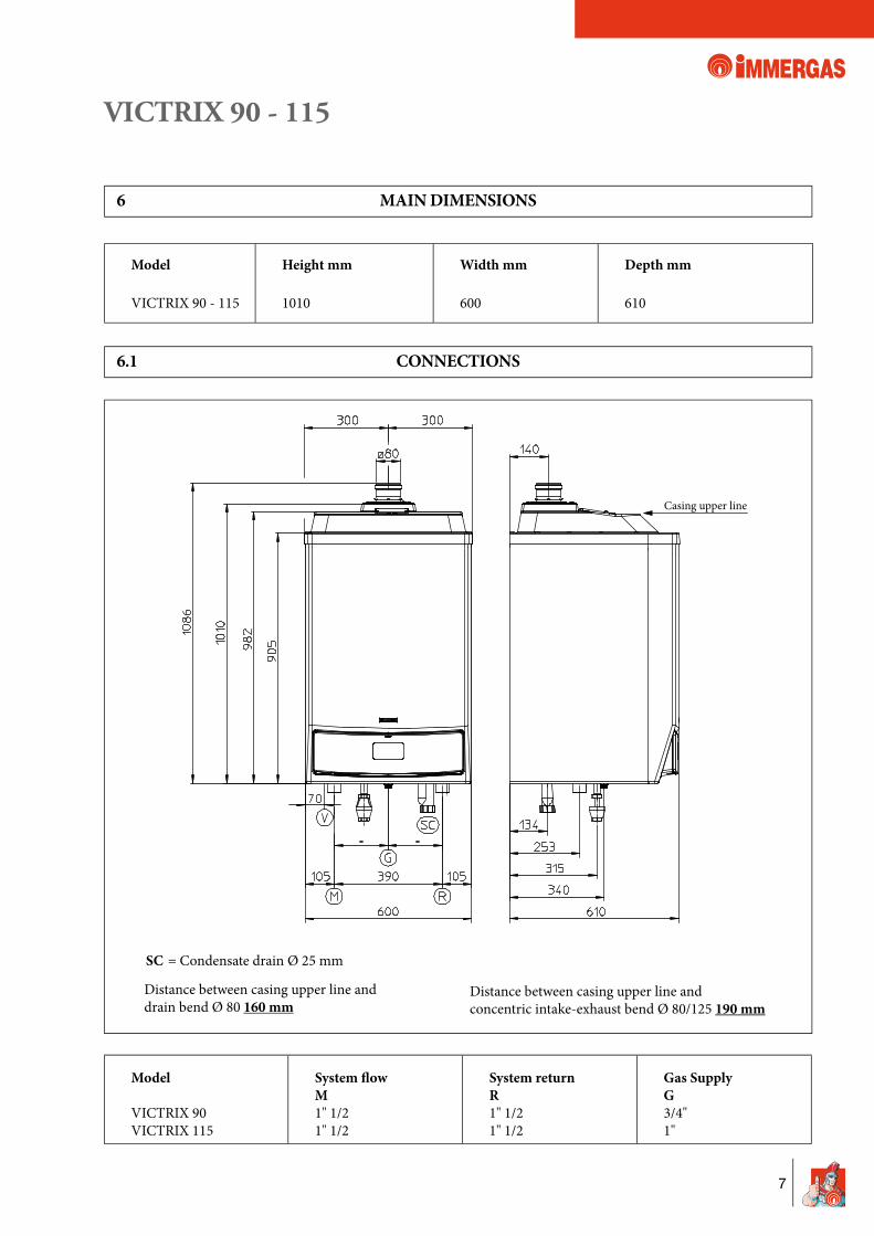
Casing upper line
6 MAIN DIMENSIONS
6.1 CONNECTIONS
Distance between casing upper line and drain bend Ø 80 160 mm
Distance between casing upper line andconcentric intake-exhaust bend Ø 80/125 190 mm
Model
VICTRIX 90VICTRIX 115
System � owM1" 1/21" 1/2
System returnR1" 1/21" 1/2
Gas SupplyG3/4"1"
Model
VICTRIX 90 - 115
Height mm
1010
Width mm
600
Depth mm
610
SC = Condensate drain Ø 25 mm
VICTRIX 90 - 115
8
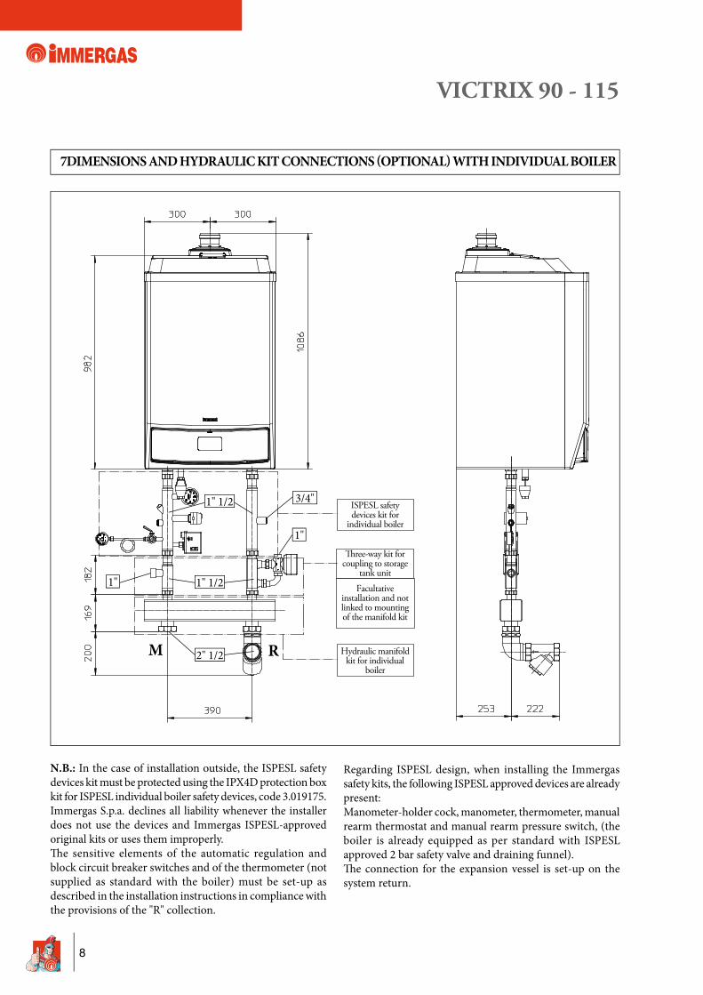
7 DIMENSIONS AND HYDRAULIC KIT CONNECTIONS (OPTIONAL) WITH INDIVIDUAL BOILER
N.B.: In the case of installation outside, the ISPESL safety devices kit must be protected using the IPX4D protection box kit for ISPESL individual boiler safety devices, code 3.019175.Immergas S.p.a. declines all liability whenever the installer does not use the devices and Immergas ISPESL-approved original kits or uses them improperly. Th e sensitive elements of the automatic regulation and block circuit breaker switches and of the thermometer (not supplied as standard with the boiler) must be set-up as described in the installation instructions in compliance with the provisions of the "R" collection.
Regarding ISPESL design, when installing the Immergas safety kits, the following ISPESL approved devices are already present: Manometer-holder cock, manometer, thermometer, manual rearm thermostat and manual rearm pressure switch, (the boiler is already equipped as per standard with ISPESL approved 2 bar safety valve and draining funnel).Th e connection for the expansion vessel is set-up on the system return.
M R
1" 1/2
1" 1/2
1"
2" 1/2
1"
3/4"
VICTRIX 90 - 115
9
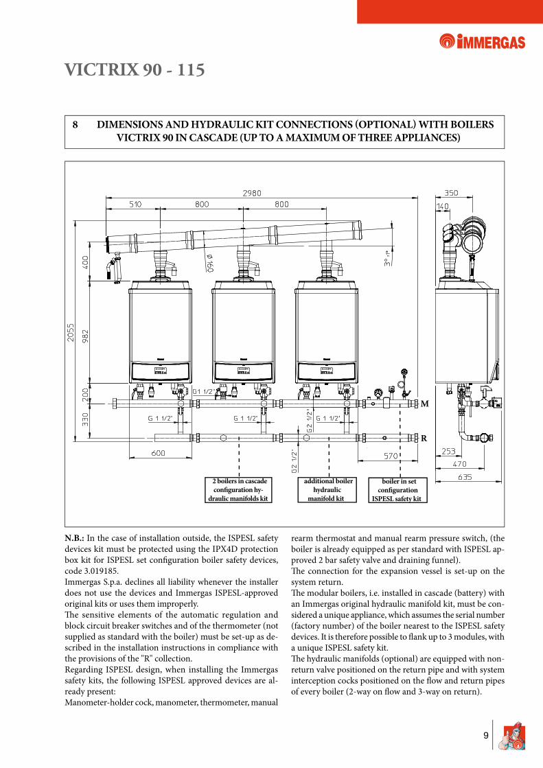
8 DIMENSIONS AND HYDRAULIC KIT CONNECTIONS (OPTIONAL) WITH BOILERSVICTRIX 90 IN CASCADE (UP TO A MAXIMUM OF THREE APPLIANCES)
N.B.: In the case of installation outside, the ISPESL safety devices kit must be protected using the IPX4D protection box kit for ISPESL set confi guration boiler safety devices, code 3.019185.Immergas S.p.a. declines all liability whenever the installer does not use the devices and Immergas ISPESL-approved original kits or uses them improperly. Th e sensitive elements of the automatic regulation and block circuit breaker switches and of the thermometer (not supplied as standard with the boiler) must be set-up as de-scribed in the installation instructions in compliance with the provisions of the "R" collection.Regarding ISPESL design, when installing the Immergas safety kits, the following ISPESL approved devices are al-ready present: Manometer-holder cock, manometer, thermometer, manual
rearm thermostat and manual rearm pressure switch, (the boiler is already equipped as per standard with ISPESL ap-proved 2 bar safety valve and draining funnel).Th e connection for the expansion vessel is set-up on the system return.Th e modular boilers, i.e. installed in cascade (battery) with an Immergas original hydraulic manifold kit, must be con-sidered a unique appliance, which assumes the serial number (factory number) of the boiler nearest to the ISPESL safety devices. It is therefore possible to fl ank up to 3 modules, with a unique ISPESL safety kit.Th e hydraulic manifolds (optional) are equipped with non-return valve positioned on the return pipe and with system interception cocks positioned on the fl ow and return pipes of every boiler (2-way on fl ow and 3-way on return).
M
R
2 boilers in cascade con� guration hy-
draulic manifolds kit
additional boiler hydraulic
manifold kit
boiler in set con� guration
ISPESL safety kit
VICTRIX 90 - 115
10
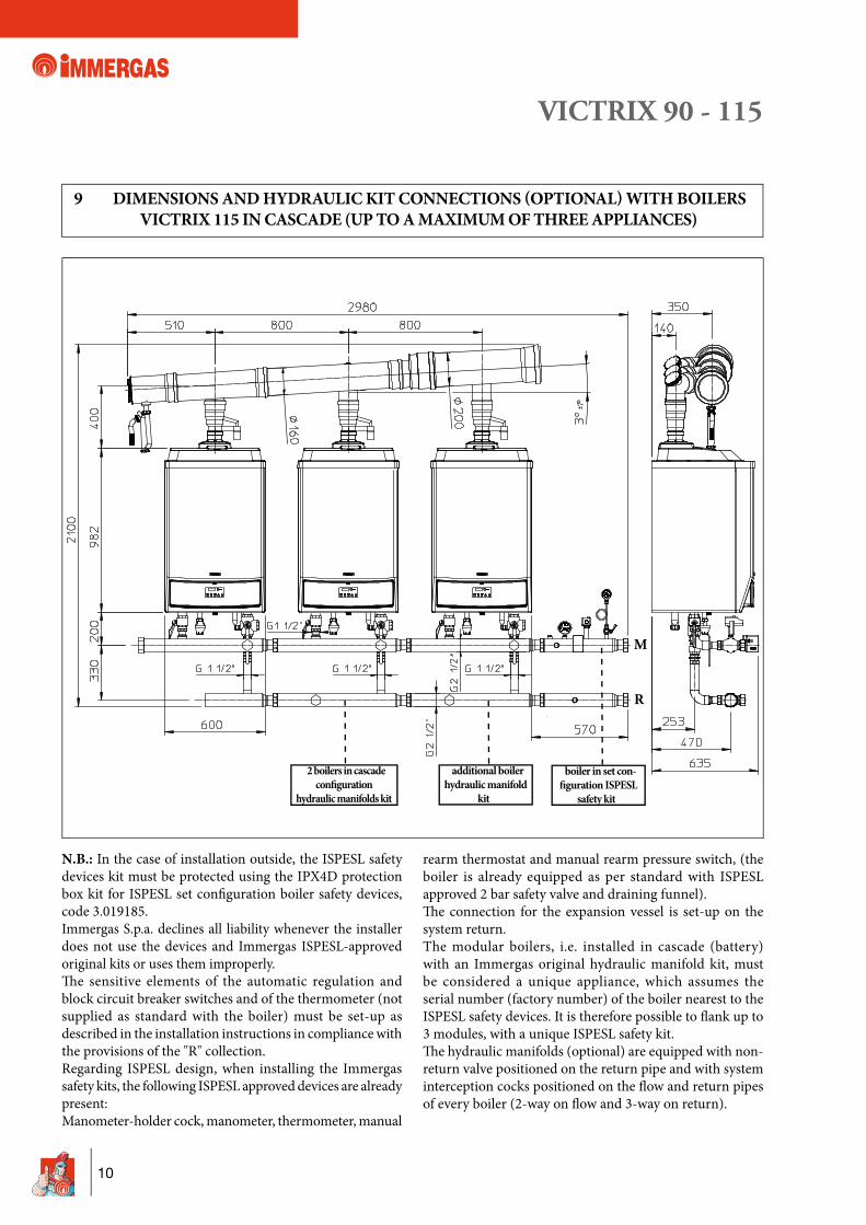
9 DIMENSIONS AND HYDRAULIC KIT CONNECTIONS (OPTIONAL) WITH BOILERSVICTRIX 115 IN CASCADE (UP TO A MAXIMUM OF THREE APPLIANCES)
M
R
N.B.: In the case of installation outside, the ISPESL safety devices kit must be protected using the IPX4D protection box kit for ISPESL set confi guration boiler safety devices, code 3.019185.Immergas S.p.a. declines all liability whenever the installer does not use the devices and Immergas ISPESL-approved original kits or uses them improperly. Th e sensitive elements of the automatic regulation and block circuit breaker switches and of the thermometer (not supplied as standard with the boiler) must be set-up as described in the installation instructions in compliance with the provisions of the "R" collection.Regarding ISPESL design, when installing the Immergas safety kits, the following ISPESL approved devices are already present: Manometer-holder cock, manometer, thermometer, manual
rearm thermostat and manual rearm pressure switch, (the boiler is already equipped as per standard with ISPESL approved 2 bar safety valve and draining funnel).Th e connection for the expansion vessel is set-up on the system return.The modular boilers, i.e. installed in cascade (battery) with an Immergas original hydraulic manifold kit, must be considered a unique appliance, which assumes the serial number (factory number) of the boiler nearest to the ISPESL safety devices. It is therefore possible to fl ank up to 3 modules, with a unique ISPESL safety kit.Th e hydraulic manifolds (optional) are equipped with non-return valve positioned on the return pipe and with system interception cocks positioned on the fl ow and return pipes of every boiler (2-way on fl ow and 3-way on return).
2 boilers in cascade con� guration
hydraulic manifolds kit
additional boiler hydraulic manifold
kit
boiler in set con-� guration ISPESL
safety kit
VICTRIX 90 - 115
11
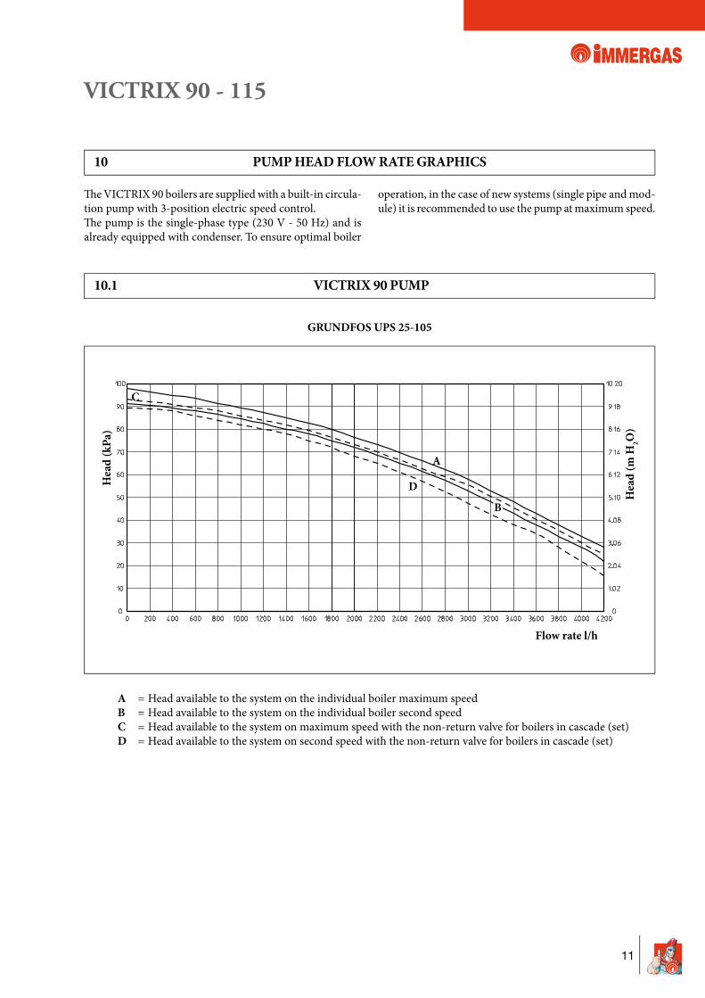
10 PUMP HEAD FLOW RATE GRAPHICS
Th e VICTRIX 90 boilers are supplied with a built-in circula-tion pump with 3-position electric speed control. Th e pump is the single-phase type (230 V - 50 Hz) and is already equipped with condenser. To ensure optimal boiler
operation, in the case of new systems (single pipe and mod-ule) it is recommended to use the pump at maximum speed.
A = Head available to the system on the individual boiler maximum speed B = Head available to the system on the individual boiler second speed C = Head available to the system on maximum speed with the non-return valve for boilers in cascade (set) D = Head available to the system on second speed with the non-return valve for boilers in cascade (set)
GRUNDFOS UPS 25-105
Hea
d (k
Pa)
Flow rate l/h
C
10.1 VICTRIX 90 PUMP
D
Hea
d (m
H2O
)
A
B
VICTRIX 90 - 115
12
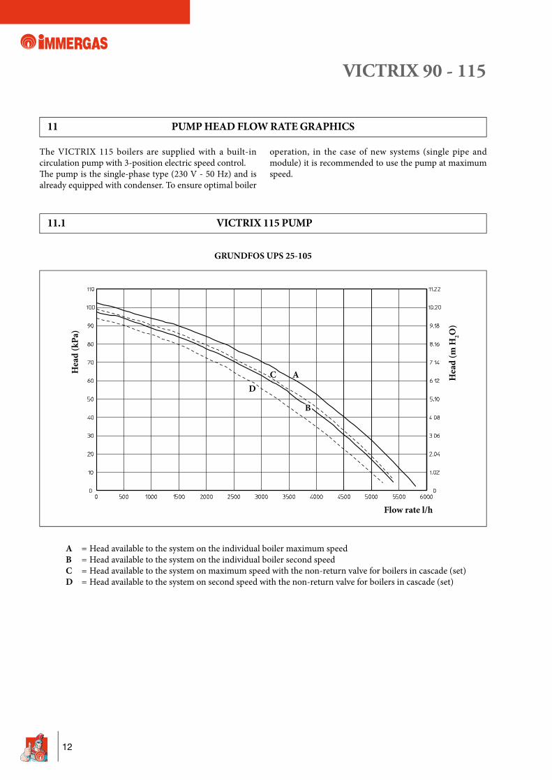
11 PUMP HEAD FLOW RATE GRAPHICS
The VICTRIX 115 boilers are supplied with a built-in circulation pump with 3-position electric speed control. Th e pump is the single-phase type (230 V - 50 Hz) and is already equipped with condenser. To ensure optimal boiler
operation, in the case of new systems (single pipe and module) it is recommended to use the pump at maximum speed.
A = Head available to the system on the individual boiler maximum speed B = Head available to the system on the individual boiler second speed C = Head available to the system on maximum speed with the non-return valve for boilers in cascade (set) D = Head available to the system on second speed with the non-return valve for boilers in cascade (set)
GRUNDFOS UPS 25-105
Hea
d (k
Pa)
Flow rate l/h
C
11.1 VICTRIX 115 PUMP
D
Hea
d (m
H2O
)
A
B
VICTRIX 90 - 115
13
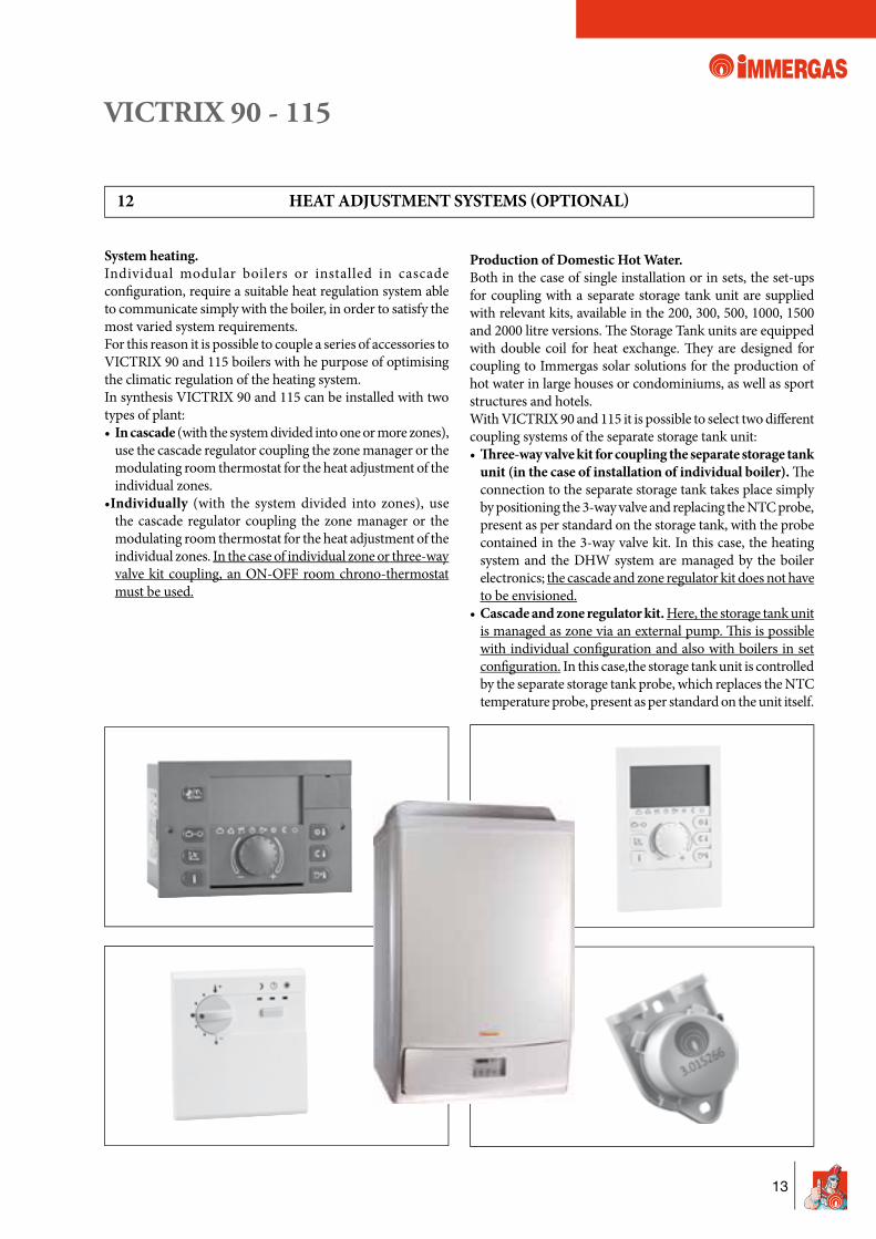
12 HEAT ADJUSTMENT SYSTEMS (OPTIONAL)
System heating.Individual modular boilers or installed in cascade confi guration, require a suitable heat regulation system able to communicate simply with the boiler, in order to satisfy the most varied system requirements.For this reason it is possible to couple a series of accessories to VICTRIX 90 and 115 boilers with he purpose of optimising the climatic regulation of the heating system.In synthesis VICTRIX 90 and 115 can be installed with two types of plant:• In cascade (with the system divided into one or more zones),
use the cascade regulator coupling the zone manager or the modulating room thermostat for the heat adjustment of the individual zones.
•Individually (with the system divided into zones), use the cascade regulator coupling the zone manager or the modulating room thermostat for the heat adjustment of the individual zones. In the case of individual zone or three-way valve kit coupling, an ON-OFF room chrono-thermostat must be used.
Production of Domestic Hot Water.Both in the case of single installation or in sets, the set-ups for coupling with a separate storage tank unit are supplied with relevant kits, available in the 200, 300, 500, 1000, 1500 and 2000 litre versions. Th e Storage Tank units are equipped with double coil for heat exchange. Th ey are designed for coupling to Immergas solar solutions for the production of hot water in large houses or condominiums, as well as sport structures and hotels.With VICTRIX 90 and 115 it is possible to select two diff erent coupling systems of the separate storage tank unit:• £ ree-way valve kit for coupling the separate storage tank
unit (in the case of installation of individual boiler). Th e connection to the separate storage tank takes place simply by positioning the 3-way valve and replacing the NTC probe, present as per standard on the storage tank, with the probe contained in the 3-way valve kit. In this case, the heating system and the DHW system are managed by the boiler electronics; the cascade and zone regulator kit does not have to be envisioned.
• Cascade and zone regulator kit. Here, the storage tank unit is managed as zone via an external pump. Th is is possible with individual confi guration and also with boilers in set confi guration. In this case,the storage tank unit is controlled by the separate storage tank probe, which replaces the NTC temperature probe, present as per standard on the unit itself.
VICTRIX 90 - 115
14
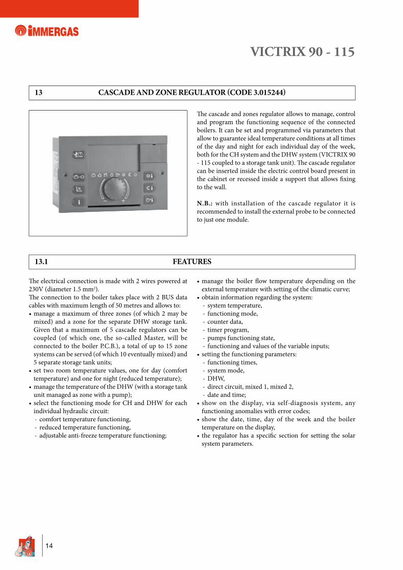
13 CASCADE AND ZONE REGULATOR (CODE 3.015244)
Th e cascade and zones regulator allows to manage, control and program the functioning sequence of the connected boilers. It can be set and programmed via parameters that allow to guarantee ideal temperature conditions at all times of the day and night for each individual day of the week, both for the CH system and the DHW system (VICTRIX 90 - 115 coupled to a storage tank unit). Th e cascade regulator can be inserted inside the electric control board present in the cabinet or recessed inside a support that allows fi xing to the wall.
N.B.: with installation of the cascade regulator it is recommended to install the external probe to be connected to just one module.
13.1 FEATURES
Th e electrical connection is made with 2 wires powered at 230V (diameter 1.5 mm2).Th e connection to the boiler takes place with 2 BUS data cables with maximum length of 50 metres and allows to:• manage a maximum of three zones (of which 2 may be
mixed) and a zone for the separate DHW storage tank. Given that a maximum of 5 cascade regulators can be coupled (of which one, the so-called Master, will be connected to the boiler P.C.B.), a total of up to 15 zone systems can be served (of which 10 eventually mixed) and 5 separate storage tank units;
• set two room temperature values, one for day (comfort temperature) and one for night (reduced temperature);
• manage the temperature of the DHW (with a storage tank unit managed as zone with a pump);
• select the functioning mode for CH and DHW for each individual hydraulic circuit:
- comfort temperature functioning, - reduced temperature functioning, - adjustable anti-freeze temperature functioning;
• manage the boiler fl ow temperature depending on the external temperature with setting of the climatic curve;
• obtain information regarding the system: - system temperature, - functioning mode, - counter data, - timer program, - pumps functioning state, - functioning and values of the variable inputs;• setting the functioning parameters: - functioning times, - system mode, - DHW, - direct circuit, mixed 1, mixed 2, - date and time;• show on the display, via self-diagnosis system, any
functioning anomalies with error codes;• show the date, time, day of the week and the boiler
temperature on the display,• the regulator has a specifi c section for setting the solar
system parameters.
VICTRIX 90 - 115
15
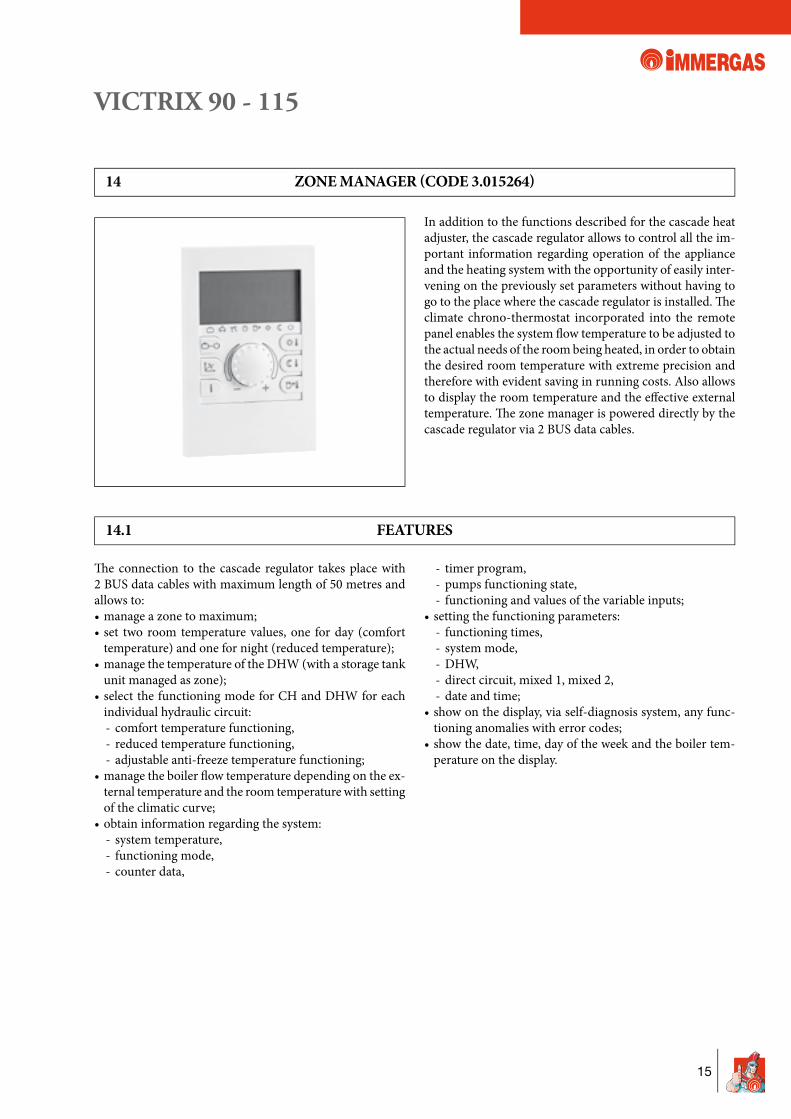
14 ZONE MANAGER (CODE 3.015264)
In addition to the functions described for the cascade heat adjuster, the cascade regulator allows to control all the im-portant information regarding operation of the appliance and the heating system with the opportunity of easily inter-vening on the previously set parameters without having to go to the place where the cascade regulator is installed. Th e climate chrono-thermostat incorporated into the remote panel enables the system fl ow temperature to be adjusted to the actual needs of the room being heated, in order to obtain the desired room temperature with extreme precision and therefore with evident saving in running costs. Also allows to display the room temperature and the eff ective external temperature. Th e zone manager is powered directly by the cascade regulator via 2 BUS data cables.
14.1 FEATURES
Th e connection to the cascade regulator takes place with 2 BUS data cables with maximum length of 50 metres and allows to:• manage a zone to maximum;• set two room temperature values, one for day (comfort
temperature) and one for night (reduced temperature);• manage the temperature of the DHW (with a storage tank
unit managed as zone);• select the functioning mode for CH and DHW for each
individual hydraulic circuit: - comfort temperature functioning, - reduced temperature functioning, - adjustable anti-freeze temperature functioning;• manage the boiler fl ow temperature depending on the ex-
ternal temperature and the room temperature with setting of the climatic curve;
• obtain information regarding the system: - system temperature, - functioning mode, - counter data,
- timer program, - pumps functioning state, - functioning and values of the variable inputs;• setting the functioning parameters: - functioning times, - system mode, - DHW, - direct circuit, mixed 1, mixed 2, - date and time;• show on the display, via self-diagnosis system, any func-
tioning anomalies with error codes;• show the date, time, day of the week and the boiler tem-
perature on the display.
VICTRIX 90 - 115
16
16 EXTERNAL PROBE (CODE 3.015266)
Th e external probe allows to decrease or increase the max. fl ow temperature to the system when the external tem-perature increases or decreases, in order to adjust the heat supplied to the system according to the change in external temperature.Th e probe is connected via two wires directly to the boiler terminal board. Once connected, it always acts without heat regulation kit.In the case of boilers installed in set confi guration (several boilers), the external probe must be connected to just one boiler.
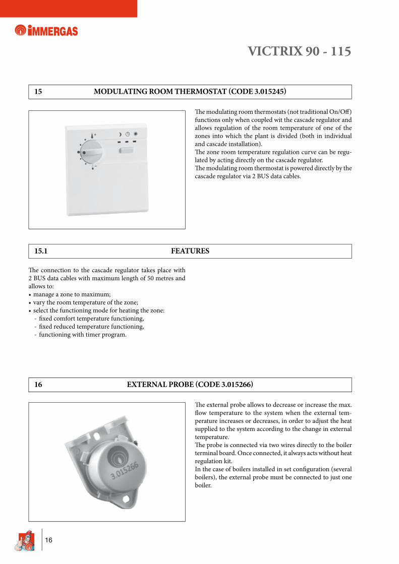
15 MODULATING ROOM THERMOSTAT (CODE 3.015245)
Th e modulating room thermostats (not traditional On/Off ) functions only when coupled wit the cascade regulator and allows regulation of the room temperature of one of the zones into which the plant is divided (both in individual and cascade installation).Th e zone room temperature regulation curve can be regu-lated by acting directly on the cascade regulator.Th e modulating room thermostat is powered directly by the cascade regulator via 2 BUS data cables.
15.1 FEATURES
Th e connection to the cascade regulator takes place with 2 BUS data cables with maximum length of 50 metres and allows to:• manage a zone to maximum;• vary the room temperature of the zone;• select the functioning mode for heating the zone: - fi xed comfort temperature functioning, - fi xed reduced temperature functioning, - functioning with timer program.
VICTRIX 90 - 115
17
17 SYSTEM EXAMPLES OF INDIVIDUAL 90-115 VICTRIX BOILERS
KEY
:
1 -
VIC
TRIX
90-
115
boile
r
2 -
Cas
cade
and
zone
regu
lato
r
3 -
Zone
man
ager
4
- M
odul
atin
g ro
om th
erm
osta
t
5 -
Exte
rnal
pro
be
6 -
Zone
1 te
mpe
ratu
re p
robe
(CM
I-1)
7
- Zo
ne 2
tem
pera
ture
pro
be (C
MI-
2)
8 -
Com
mon
fl ow
pro
be
9 -
Stor
age
tank
uni
t tem
pera
ture
pro
be
10 -
Zo
ne 1
mix
ing
valv
e (C
MI-
1)
11 -
Zo
ne 2
mix
ing
valv
e (C
MI-
2)
12 -
Zo
ne 1
cent
ral h
eatin
g ci
rcui
t pum
p (C
MI-
1)
13 -
Zo
ne 2
cent
ral h
eatin
g ci
rcui
t pum
p (C
MI-
2)
14 -
Zo
ne 3
dire
ct ci
rcui
t pum
p (C
D)
15
-
Stor
age
tank
uni
t fee
ding
pum
p
16 -
Zo
ne 1
safe
ty th
erm
osta
t (C
MI-
1)
17 -
Zo
ne 2
safe
ty th
erm
osta
t (C
MI-
2)
19 -
Fu
el sh
ut-o
ff va
lve
bulb
20
-
ISPE
SL ty
pe-a
ppro
ved
man
omet
er-h
olde
r coc
k
21 -
IS
PESL
type
-app
rove
d th
erm
omet
er
22 -
IS
PESL
type
-app
rove
d m
anua
l rea
rm th
erm
osta
t
23 -
IS
PESL
type
-app
rove
d m
anua
l rea
rm p
ress
ure
sw
itch
24
-
Atta
chm
ent f
or e
xpan
sion
vess
el
25 -
Ex
pans
ion
vess
el
26 -
M
anifo
ld/m
ixer
27
-
Exte
rnal
stor
age
tank
uni
t
28 -
Fu
el sh
ut-o
ff va
lve
29
-
Non
retu
rn v
alve
30
-
Slur
ry co
llect
ion
syst
em fi
lter
31
-
Man
omet
er p
ocke
t
32 -
D
ampe
r coi
l
33 -
IS
PESL
type
-app
rove
d m
anom
eter
VICTRIX 90 - 115
18
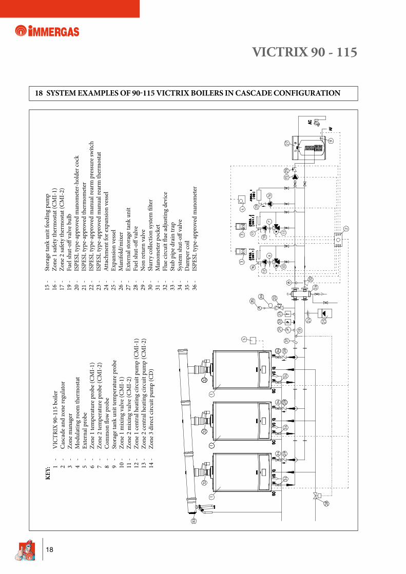
18 SYSTEM EXAMPLES OF 90-115 VICTRIX BOILERS IN CASCADE CONFIGURATION
KEY
:
1 -
VIC
TRIX
90-
115
boile
r
2 -
Cas
cade
and
zone
regu
lato
r
3 -
Zone
man
ager
4
- M
odul
atin
g ro
om th
erm
osta
t
5 -
Exte
rnal
pro
be
6 -
Zone
1 te
mpe
ratu
re p
robe
(CM
I-1)
7
- Zo
ne 2
tem
pera
ture
pro
be (C
MI-
2)
8 -
Com
mon
fl ow
pro
be
9 -
Stor
age
tank
uni
t tem
pera
ture
pro
be
10 -
Zo
ne 1
mix
ing
valv
e (C
MI-
1)
11 -
Zo
ne 2
mix
ing
valv
e (C
MI-
2)
12 -
Zo
ne 1
cent
ral h
eatin
g ci
rcui
t pum
p (C
MI-
1)
13 -
Zo
ne 2
cent
ral h
eatin
g ci
rcui
t pum
p (C
MI-
2)
14 -
Zo
ne 3
dire
ct ci
rcui
t pum
p (C
D)
15
-
Stor
age
tank
uni
t fee
ding
pum
p
16 -
Zo
ne 1
safe
ty th
erm
osta
t (C
MI-
1)
17 -
Zo
ne 2
safe
ty th
erm
osta
t (C
MI-
2)
19 -
Fu
el sh
ut-o
ff va
lve
bulb
20
-
ISPE
SL ty
pe-a
ppro
ved
man
omet
er-h
olde
r coc
k
21 -
IS
PESL
type
-app
rove
d th
erm
omet
er
22 -
IS
PESL
type
-app
rove
d m
anua
l rea
rm p
ress
ure
switc
h
23 -
IS
PESL
type
-app
rove
d m
anua
l rea
rm th
erm
osta
t
24 -
At
tach
men
t for
exp
ansio
n ve
ssel
25
-
Expa
nsio
n ve
ssel
26
-
Man
ifold
/mix
er
27 -
Ex
tern
al st
orag
e ta
nk u
nit
28
-
Fuel
shut
-off
valv
e
29 -
N
on re
turn
val
ve
30 -
Sl
urry
colle
ctio
n sy
stem
fi lte
r
31 -
M
anom
eter
poc
ket
32
-
Flue
circ
uit fl
ue
adju
stin
g de
vice
33
-
Stub
pip
e dr
ain
trap
34
-
Syst
em sh
ut-o
ff va
lve
35
-
Dam
per c
oil
36
-
ISPE
SL ty
pe-a
ppro
ved
man
omet
er
VICTRIX 90 - 115
19
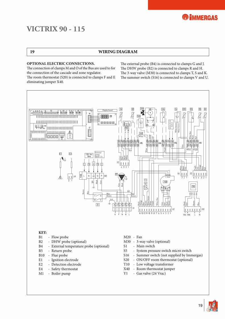
OPTIONAL ELECTRIC CONNECTIONS.Th e connection of clamps M and O of the Bus are used to for the connection of the cascade and zone regulator.Th e room thermostat (S20) is connected to clamps F and E eliminating jumper X40.
KEY: B1 - Flow probe B2 - DHW probe (optional) B4 - External temperature probe (optional) B5 - Return probe B10 - Flue probe E1 - Ignition electrode E2 - Detection electrode E4 - Safety thermostat M1 - Boiler pump
M20 - Fan M30 - 3-way valve (optional) S1 - Main switch S5 - System pressure switch micro switch S16 - Summer switch (not supplied by Immergas) S20 - ON/OFF room thermostat (optional) T10 - Low voltage transformer X40 - Room thermostat jumper Y1 - Gas valve (24 Vrac)
19 WIRING DIAGRAM
Th e external probe (B4) is connected to clamps G and J.Th e DHW probe (B2) is connected to clamps R and H.Th e 3-way valve (M30) is connected to clamps T, S and K. Th e summer switch (S16) is connected to clamps V and U.
DH
WC
H
VICTRIX 90 - 115
20
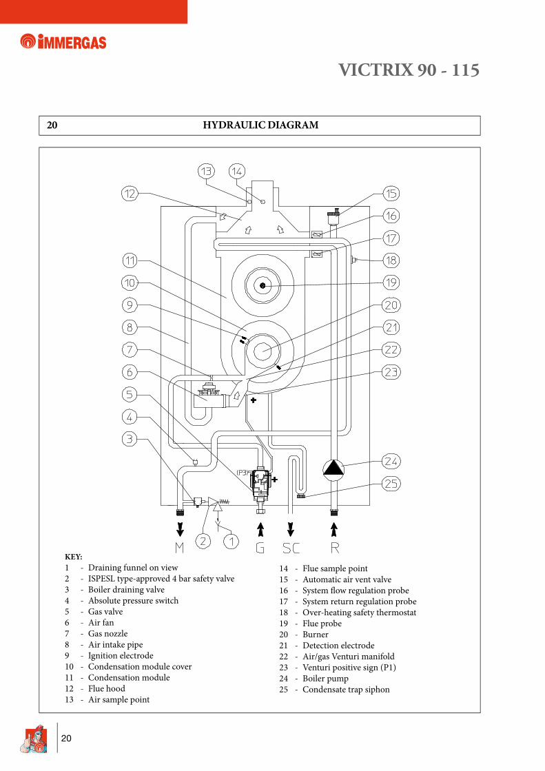
KEY: 1 - Draining funnel on view 2 - ISPESL type-approved 4 bar safety valve 3 - Boiler draining valve 4 - Absolute pressure switch 5 - Gas valve 6 - Air fan 7 - Gas nozzle 8 - Air intake pipe 9 - Ignition electrode 10 - Condensation module cover 11 - Condensation module 12 - Flue hood 13 - Air sample point
14 - Flue sample point 15 - Automatic air vent valve 16 - System fl ow regulation probe 17 - System return regulation probe 18 - Over-heating safety thermostat 19 - Flue probe 20 - Burner 21 - Detection electrode 22 - Air/gas Venturi manifold 23 - Venturi positive sign (P1) 24 - Boiler pump 25 - Condensate trap siphon
20 HYDRAULIC DIAGRAM
VICTRIX 90 - 115
21
"GREEN RANGE" INTAKE/EXHAUST KIT MUST BE USED FOR VICTRIX 90-115
21 TYPE OF INSTALLATION
The VICTRIX 90-115 boilers are type-approved for installation outside or inside the heating control unit. The "Victrix 90 -115" boilers leave the factory in "B23" confi guration (open chamber and fan assisted), to change the confi guration of the boiler to type "C" (sealed chamber and fan assisted), disassemble the Ø 80 adapter, the bracket and the gasket present on the boiler cover, in this way the relevant Ø 80/125 kits can be used.For correct installation of the boiler, the particular Immergas "Green" range air intake/fumes exhaust kits must be used as the materials, components and accessories are specifi c for this type of appliances.Th e fl ue exhaust pipes are made in plastic, in a way to guarantee high resistance to corrosion and noteworthy rapidity and functionality in installation, also thanks to the push-fi tting system and the sealing gaskets.
By varying the type of installation the classifi cation of the boiler also varies:Type C con� guration, sealed chamber and fan assisted.Installation takes place using the relevant Ø 80/125 concentric kits aft er having removed the Ø 80 adapter, the bracket and the gasket present on the boiler cover.Air intake and fl ue exhaust takes place in this way directly to the outside of the building.Th e following can be used as concentric intake/exhaust kit:Ø 80/125 horizontal concentric kit Code 3.015242;Ø 80/125 vertical concentric kit Code 3.015243.
Con� guration type B23 open chamber and forced draught.Installation takes place using the Ø 80 adapter, as per standard, with the boiler to which the relevant Ø 80 fl ue exhaust kit is connected.Air intake takes place directly from the environment in which the boiler is installed and fl ue exhaust into the fl ue or directly to the outside. It is therefore necessary to couple only one of the following fl ue exhaust kits:Ø 80 horizontal terminal kit for wall fl ue exhaustCode 3.015255;Horizontal kit Ø 80 for exhaust in fl ueCode 3.015254;Ø 80 vertical terminal kit for direct dischargeCode 3.015256.
Installed individually, always in "B23" configuration, VICTRIX 90-115 can also be coupled with the Ø 80 fl exible ducting system for condensing boilers.Th is system is particularly suitable for chimneys or fl ues (or technical slots) that are not perfectly straight, where a rigid ducting system could, in some cases, face diffi culty during installation.
Installed in cascade confi guration inside the heating control units or technical rooms, it is possible to use the relevant exhaust manifolds in the fl ue equipped with non-return devices (fl ue adjusting devices), in order to prevent the functioning boiler combustion products from interfering with the combustion circuit of other boilers that are off .
VICTRIX 90 - 115
22
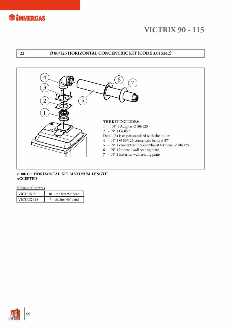
Ø 80/125 HORIZONTAL KIT MAXIMUM LENGTH ACCEPTED
Horizontal metresVICTRIX 90 10 + the fi rst 90° bendVICTRIX 115 7 + the fi rst 90° bend
22 Ø 80/125 HORIZONTAL CONCENTRIC KIT (CODE 3.015242)
2
1
3
47
5
6
THE KIT INCLUDES:1 - N° 1 Adapter Ø 80/125 2 - N° 1 GasketDetail (3) is as per standard with the boiler4 - N° 1 Ø 80/125 concentric bend at 87°5 - N° 1 concentric intake-exhaust terminal Ø 80/125 6 - N° 1 Internal wall sealing plate7 - N° 1 External wall sealing plate
VICTRIX 90 - 115
23
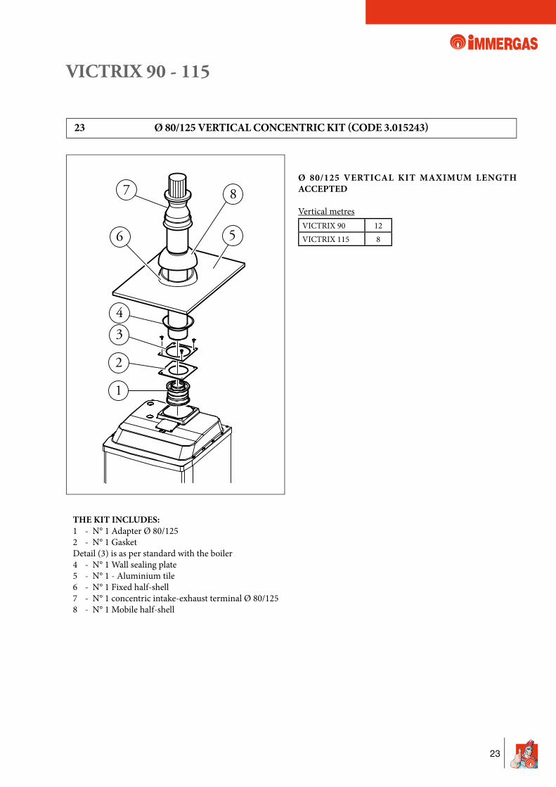
Ø 80/125 VERTICAL KIT MAXIMUM LENGTH ACCEPTED
Vertical metresVICTRIX 90 12VICTRIX 115 8
THE KIT INCLUDES:1 - N° 1 Adapter Ø 80/125 2 - N° 1 GasketDetail (3) is as per standard with the boiler4 - N° 1 Wall sealing plate5 - N° 1 - Aluminium tile 6 - N° 1 Fixed half-shell 7 - N° 1 concentric intake-exhaust terminal Ø 80/125 8 - N° 1 Mobile half-shell
23 Ø 80/125 VERTICAL CONCENTRIC KIT (CODE 3.015243)
2
1
34
5
87
6
VICTRIX 90 - 115
24
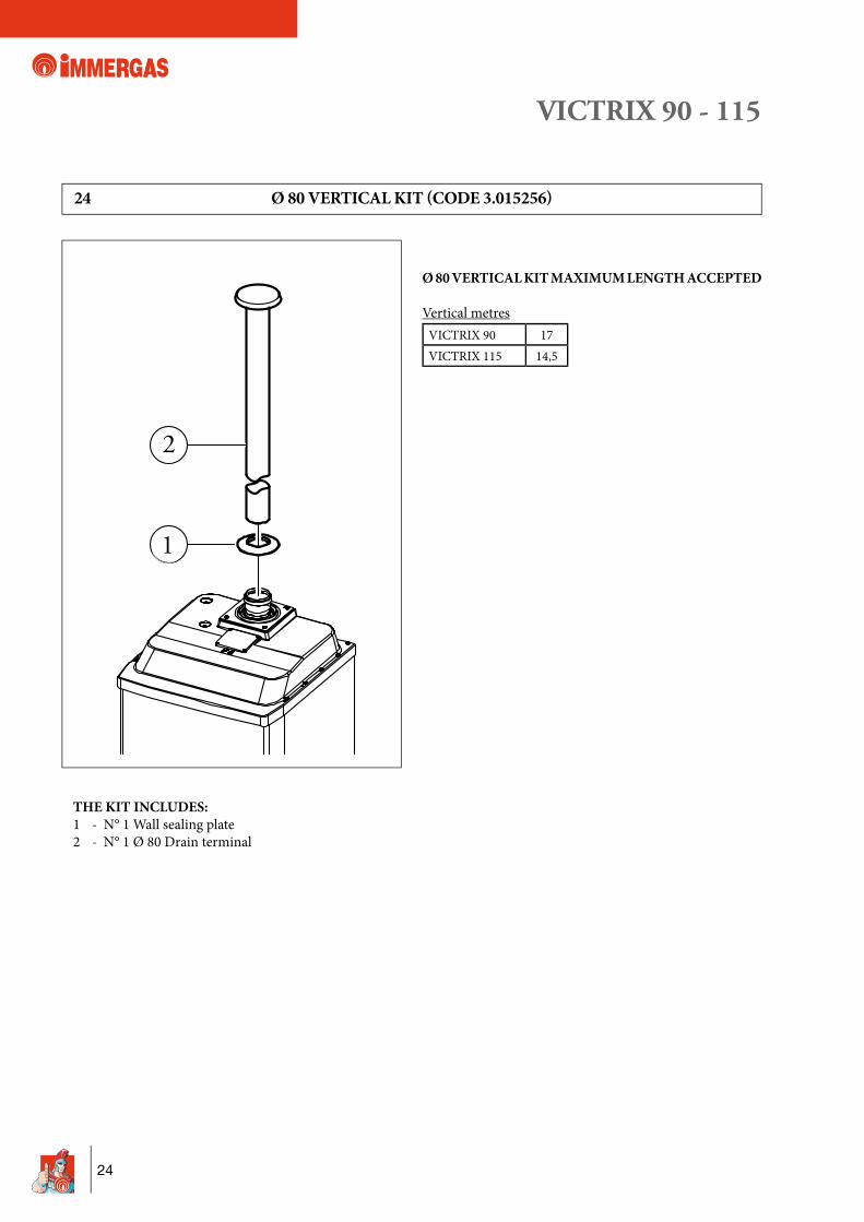
Ø 80 VERTICAL KIT MAXIMUM LENGTH ACCEPTED
Vertical metresVICTRIX 90 17VICTRIX 115 14,5
THE KIT INCLUDES:1 - N° 1 Wall sealing plate2 - N° 1 Ø 80 Drain terminal
24 Ø 80 VERTICAL KIT (CODE 3.015256)
2
1
VICTRIX 90 - 115
25
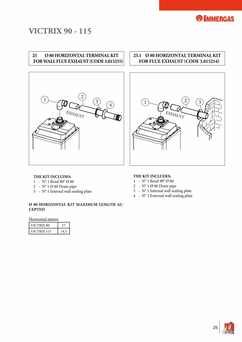
Ø 80 HORIZONTAL KIT MAXIMUM LENGTH AC-CEPTED
Horizontal metresVICTRIX 90 17VICTRIX 115 14,5
25 Ø 80 HORIZONTAL TERMINAL KIT FOR WALL FLUE EXHAUST (CODE 3.015255)
25.1 Ø 80 HORIZONTAL TERMINAL KIT FOR FLUE EXHAUST (CODE 3.015254)
THE KIT INCLUDES:1 - N° 1 Bend 90° Ø 802 - N° 1 Ø 80 Drain pipe3 - N° 1 Internal wall sealing plate
THE KIT INCLUDES:1 - N° 1 Bend 90° Ø 802 - N° 1 Ø 80 Drain pipe3 - N° 1 Internal wall sealing plate4 - N° 1 External wall sealing plate
1 32
EXHAUST
14
32
EXHAUST
VICTRIX 90 - 115
26
1
487
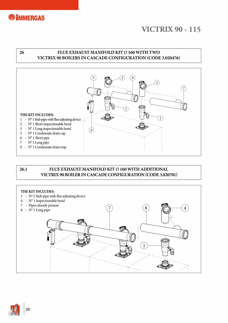
26.1 FLUE EXHAUST MANIFOLD KIT Ø 160 WITH ADDITIONAL VICTRIX 90 BOILER IN CASCADE CONFIGURATION (CODE 3.020701)
THE KIT INCLUDES:1 - N° 1 Stub pipe with flue adjusting device2 - N° 1 Short inspectionable bend3 - N° 1 Long inspectionable bend5 - N° 1 Condensate drain cap6 - N° 1 Short pipe7 - N° 1 Long pipe9 - N° 1 Condensate drain trap
THE KIT INCLUDES:1 - N° 1 Stub pipe with fl ue adjusting device4 - N° 1 Inspectionable bend7 - Pipes already present8 - N° 1 Long pipe
26 FLUE EXHAUST MANIFOLD KIT Ø 160 WITH TWO VICTRIX 90 BOILERS IN CASCADE CONFIGURATION (CODE 3.020476)
7
6
1
1
9
23
5
VICTRIX 90 - 115
27
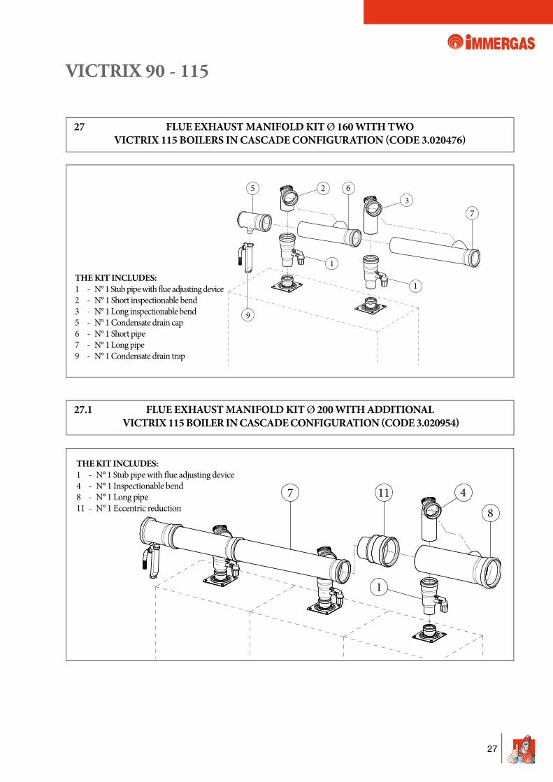
27.1 FLUE EXHAUST MANIFOLD KIT Ø 200 WITH ADDITIONAL VICTRIX 115 BOILER IN CASCADE CONFIGURATION (CODE 3.020954)
THE KIT INCLUDES:1 - N° 1 Stub pipe with fl ue adjusting device2 - N° 1 Short inspectionable bend3 - N° 1 Long inspectionable bend5 - N° 1 Condensate drain cap6 - N° 1 Short pipe7 - N° 1 Long pipe9 - N° 1 Condensate drain trap
27 FLUE EXHAUST MANIFOLD KIT Ø 160 WITH TWO VICTRIX 115 BOILERS IN CASCADE CONFIGURATION (CODE 3.020476)
7
6
1
1
9
23
5
1
84117
THE KIT INCLUDES:1 - N° 1 Stub pipe with fl ue adjusting device4 - N° 1 Inspectionable bend8 - N° 1 Long pipe11 - N° 1 Eccentric reduction
VICTRIX 90 - 115
28
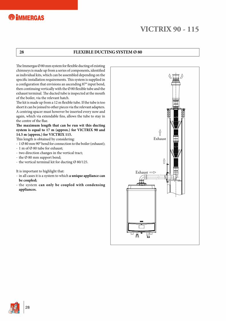
28 FLEXIBLE DUCTING SYSTEM Ø 80
Th e Immergas Ø 80 mm system for fl exible ducting of existing chimneys is made up from a series of components, identifi ed as individual kits, which can be assembled depending on the specifi c installation requirements. Th is system is supplied in a confi guration that envisions an ascending 87° input bend, then continuing vertically with the Ø 80 fl exible tube and the exhaust terminal. Th e ducted tube is inspected at the mouth of the boiler, via the relevant hatch. Th e kit is made up from a 12 m fl exible tube. If the tube is too short it can be joined to other pieces via the relevant adapters.A centring spacer must however be inserted every now and again, which via extendable fi ns, allows the tube to stay in the centre of the fl ue.£ e maximum length that can be run wit this ducting system is equal to 17 m (approx.) for VICTRIX 90 and 14.5 m (approx.) for VICTRIX 115.Th is length is obtained by considering:- 1 Ø 80 mm 90° bend for connection to the boiler (exhaust);- 1 m of Ø 80 tube for exhaust;- two direction changes in the vertical tract;- the Ø 80 mm support bend;- the vertical terminal kit for ducting Ø 80/125.
It is important to highlight that:- in all cases it is a system to which a unique appliance can
be coupled;- the system can only be coupled with condensing
appliances.
VICTRIX 90 - 115
29
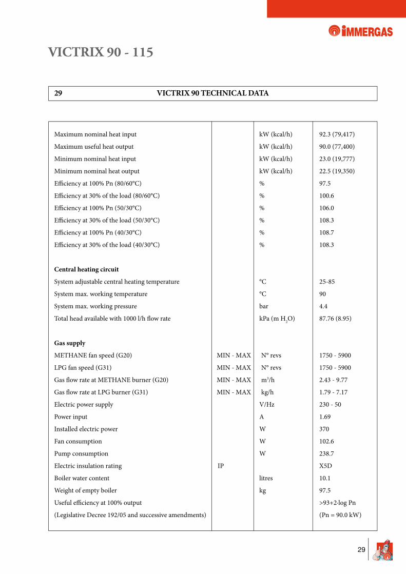
29 VICTRIX 90 TECHNICAL DATA
Maximum nominal heat input kW (kcal/h) 92.3 (79,417)
Maximum useful heat output kW (kcal/h) 90.0 (77,400)
Minimum nominal heat input kW (kcal/h) 23.0 (19,777)
Minimum nominal heat output kW (kcal/h) 22.5 (19,350)
Effi ciency at 100% Pn (80/60°C) % 97.5
Effi ciency at 30% of the load (80/60°C) % 100.6
Effi ciency at 100% Pn (50/30°C) % 106.0
Effi ciency at 30% of the load (50/30°C) % 108.3
Effi ciency at 100% Pn (40/30°C) % 108.7
Effi ciency at 30% of the load (40/30°C) % 108.3
Central heating circuit
System adjustable central heating temperature °C 25-85
System max. working temperature °C 90
System max. working pressure bar 4.4
Total head available with 1000 l/h fl ow rate kPa (m H2O) 87.76 (8.95)
Gas supply
METHANE fan speed (G20) MIN - MAX N° revs 1750 - 5900
LPG fan speed (G31) MIN - MAX N° revs 1750 - 5900
Gas fl ow rate at METHANE burner (G20) MIN - MAX m3/h 2.43 - 9.77
Gas fl ow rate at LPG burner (G31) MIN - MAX kg/h 1.79 - 7.17
Electric power supply V/Hz 230 - 50
Power input A 1.69
Installed electric power W 370
Fan consumption W 102.6
Pump consumption W 238.7
Electric insulation rating IP X5D
Boiler water content litres 10.1
Weight of empty boiler kg 97.5
Useful effi ciency at 100% output >93+2·log Pn
(Legislative Decree 192/05 and successive amendments) (Pn = 90.0 kW)
VICTRIX 90 - 115
30
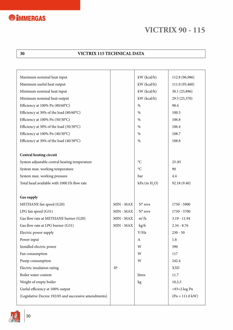
30 VICTRIX 115 TECHNICAL DATA
Maximum nominal heat input kW (kcal/h) 112.8 (96,986)
Maximum useful heat output kW (kcal/h) 111.0 (95,460)
Minimum nominal heat input kW (kcal/h) 30.1 (25,896)
Minimum nominal heat output kW (kcal/h) 29.5 (25,370)
Effi ciency at 100% Pn (80/60°C) % 98.4
Effi ciency at 30% of the load (80/60°C) % 100.3
Effi ciency at 100% Pn (50/30°C) % 106.8
Effi ciency at 30% of the load (50/30°C) % 106.4
Effi ciency at 100% Pn (40/30°C) % 108.7
Effi ciency at 30% of the load (40/30°C) % 108.8
Central heating circuit
System adjustable central heating temperature °C 25-85
System max. working temperature °C 90
System max. working pressure bar 4.4
Total head available with 1000 l/h fl ow rate kPa (m H2O) 92.18 (9.40)
Gas supply
METHANE fan speed (G20) MIN - MAX N° revs 1750 - 5900
LPG fan speed (G31) MIN - MAX N° revs 1750 - 5700
Gas fl ow rate at METHANE burner (G20) MIN - MAX m3/h 3.19 - 11.94
Gas fl ow rate at LPG burner (G31) MIN - MAX kg/h 2.34 - 8.76
Electric power supply V/Hz 230 - 50
Power input A 1.8
Installed electric power W 390
Fan consumption W 117
Pump consumption W 242.4
Electric insulation rating IP X5D
Boiler water content litres 11.7
Weight of empty boiler kg 10,5,5
Useful effi ciency at 100% output >93+2·log Pn
(Legislative Decree 192/05 and successive amendments) (Pn = 111.0 kW)
VICTRIX 90 - 115
31
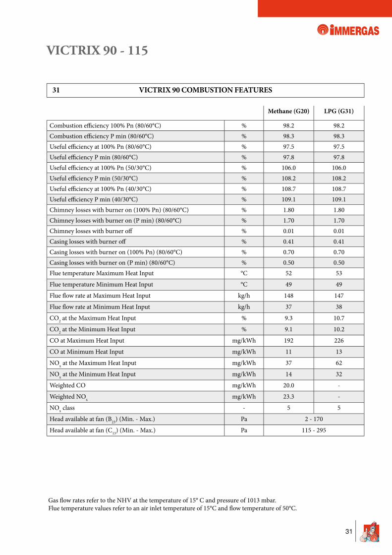
Gas fl ow rates refer to the NHV at the temperature of 15° C and pressure of 1013 mbar. Flue temperature values refer to an air inlet temperature of 15°C and fl ow temperature of 50°C.
31 VICTRIX 90 COMBUSTION FEATURES
Methane (G20) LPG (G31)
Combustion effi ciency 100% Pn (80/60°C) % 98.2 98.2Combustion effi ciency P min (80/60°C) % 98.3 98.3Useful effi ciency at 100% Pn (80/60°C) % 97.5 97.5Useful effi ciency P min (80/60°C) % 97.8 97.8Useful effi ciency at 100% Pn (50/30°C) % 106.0 106.0Useful effi ciency P min (50/30°C) % 108.2 108.2Useful effi ciency at 100% Pn (40/30°C) % 108.7 108.7Useful effi ciency P min (40/30°C) % 109.1 109.1Chimney losses with burner on (100% Pn) (80/60°C) % 1.80 1.80Chimney losses with burner on (P min) (80/60°C) % 1.70 1.70Chimney losses with burner off % 0.01 0.01Casing losses with burner off % 0.41 0.41Casing losses with burner on (100% Pn) (80/60°C) % 0.70 0.70Casing losses with burner on (P min) (80/60°C) % 0.50 0.50Flue temperature Maximum Heat Input °C 52 53
Flue temperature Minimum Heat Input °C 49 49
Flue fl ow rate at Maximum Heat Input kg/h 148 147
Flue fl ow rate at Minimum Heat Input kg/h 37 38
CO2 at the Maximum Heat Input % 9.3 10.7
CO2 at the Minimum Heat Input % 9.1 10.2
CO at Maximum Heat Input mg/kWh 192 226
CO at Minimum Heat Input mg/kWh 11 13
NOx at the Maximum Heat Input mg/kWh 37 62
NOx at the Minimum Heat Input mg/kWh 14 32
Weighted CO mg/kWh 20.0 -
Weighted NOx mg/kWh 23.3 -
NOx class - 5 5
Head available at fan (B23) (Min. - Max.) Pa 2 - 170
Head available at fan (C13) (Min. - Max.) Pa 115 - 295
VICTRIX 90 - 115
32
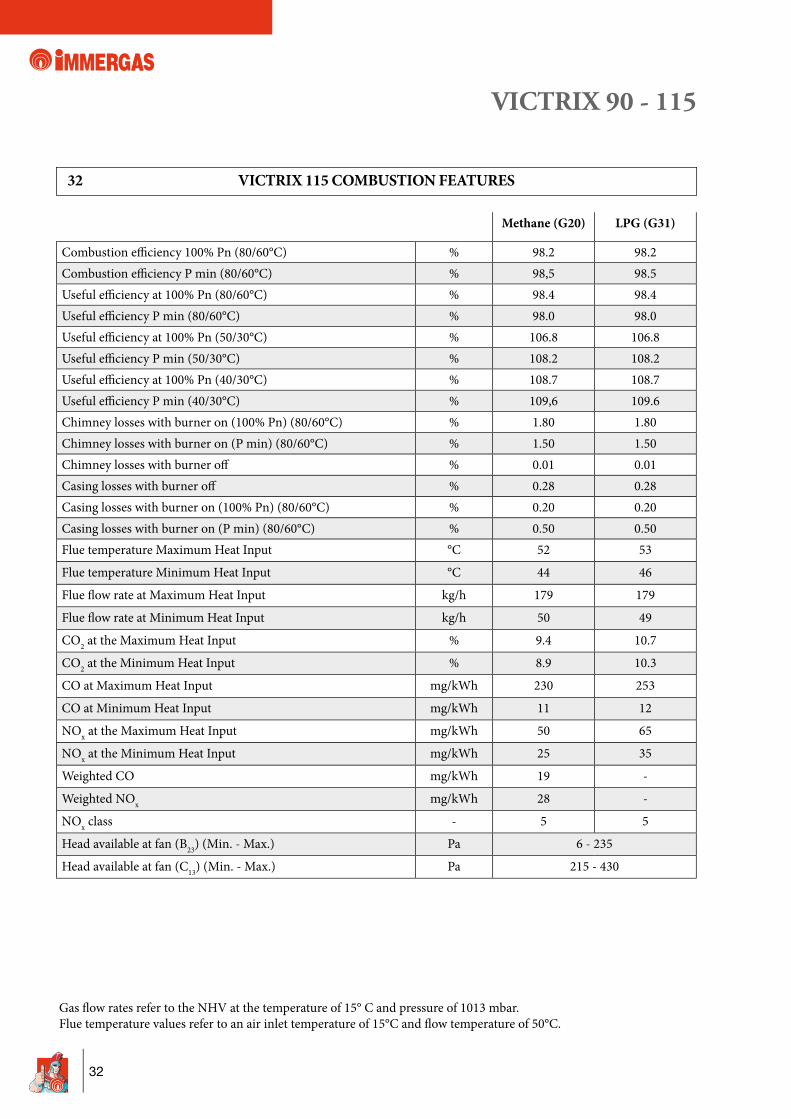
Gas fl ow rates refer to the NHV at the temperature of 15° C and pressure of 1013 mbar. Flue temperature values refer to an air inlet temperature of 15°C and fl ow temperature of 50°C.
32 VICTRIX 115 COMBUSTION FEATURES
Methane (G20) LPG (G31)
Combustion effi ciency 100% Pn (80/60°C) % 98.2 98.2Combustion effi ciency P min (80/60°C) % 98,5 98.5Useful effi ciency at 100% Pn (80/60°C) % 98.4 98.4Useful effi ciency P min (80/60°C) % 98.0 98.0Useful effi ciency at 100% Pn (50/30°C) % 106.8 106.8Useful effi ciency P min (50/30°C) % 108.2 108.2Useful effi ciency at 100% Pn (40/30°C) % 108.7 108.7Useful effi ciency P min (40/30°C) % 109,6 109.6Chimney losses with burner on (100% Pn) (80/60°C) % 1.80 1.80Chimney losses with burner on (P min) (80/60°C) % 1.50 1.50Chimney losses with burner off % 0.01 0.01Casing losses with burner off % 0.28 0.28Casing losses with burner on (100% Pn) (80/60°C) % 0.20 0.20Casing losses with burner on (P min) (80/60°C) % 0.50 0.50Flue temperature Maximum Heat Input °C 52 53
Flue temperature Minimum Heat Input °C 44 46
Flue fl ow rate at Maximum Heat Input kg/h 179 179
Flue fl ow rate at Minimum Heat Input kg/h 50 49
CO2 at the Maximum Heat Input % 9.4 10.7
CO2 at the Minimum Heat Input % 8.9 10.3
CO at Maximum Heat Input mg/kWh 230 253
CO at Minimum Heat Input mg/kWh 11 12
NOx at the Maximum Heat Input mg/kWh 50 65
NOx at the Minimum Heat Input mg/kWh 25 35
Weighted CO mg/kWh 19 -
Weighted NOx mg/kWh 28 -
NOx class - 5 5
Head available at fan (B23) (Min. - Max.) Pa 6 - 235
Head available at fan (C13) (Min. - Max.) Pa 215 - 430
VICTRIX 90 - 115
33
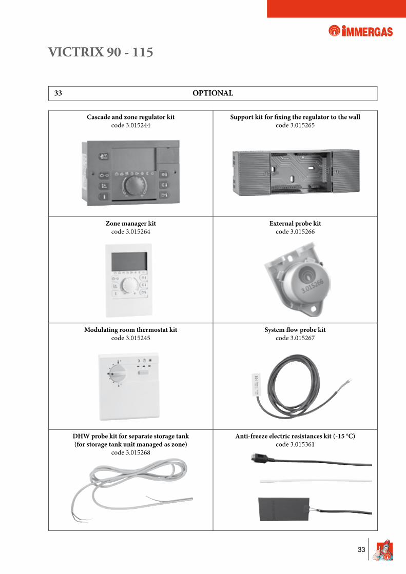
33 OPTIONAL
Cascade and zone regulator kitcode 3.015244
Support kit for � xing the regulator to the wallcode 3.015265
Zone manager kitcode 3.015264
External probe kitcode 3.015266
Modulating room thermostat kitcode 3.015245
System � ow probe kitcode 3.015267
DHW probe kit for separate storage tank(for storage tank unit managed as zone)
code 3.015268
Anti-freeze electric resistances kit (-15 °C)code 3.015361
VICTRIX 90 - 115
34
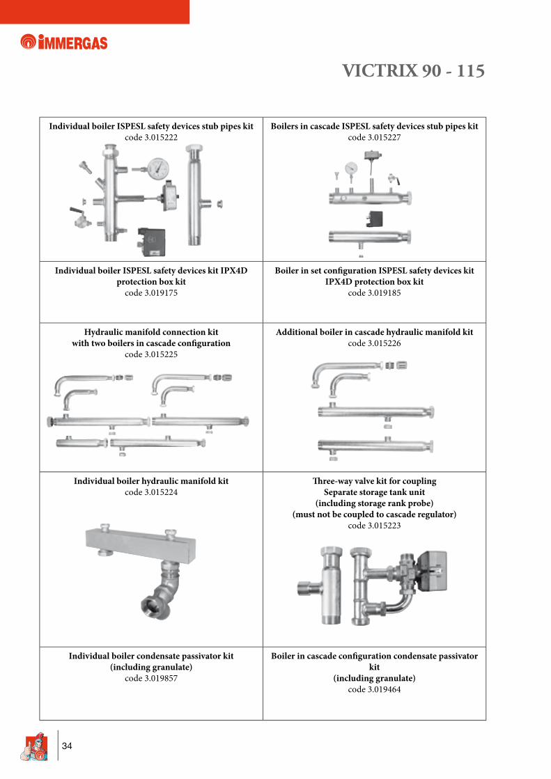
Individual boiler ISPESL safety devices stub pipes kitcode 3.015222
Boilers in cascade ISPESL safety devices stub pipes kitcode 3.015227
Individual boiler ISPESL safety devices kit IPX4D protection box kit
code 3.019175
Boiler in set con� guration ISPESL safety devices kit IPX4D protection box kit
code 3.019185
Hydraulic manifold connection kit with two boilers in cascade con� guration
code 3.015225
Additional boiler in cascade hydraulic manifold kitcode 3.015226
Individual boiler hydraulic manifold kitcode 3.015224
£ ree-way valve kit for coupling Separate storage tank unit
(including storage rank probe)(must not be coupled to cascade regulator)
code 3.015223
Individual boiler condensate passivator kit(including granulate)
code 3.019857
Boiler in cascade con� guration condensate passivator kit
(including granulate)code 3.019464
VICTRIX 90 - 115
35
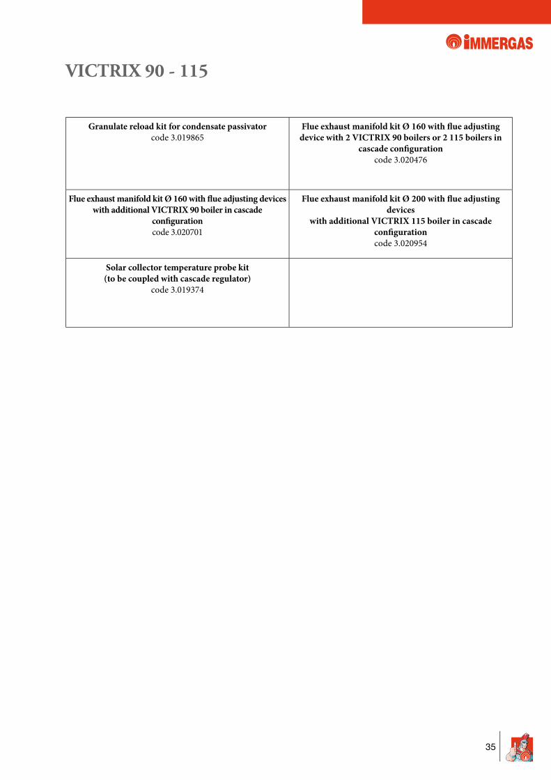
Granulate reload kit for condensate passivatorcode 3.019865
Flue exhaust manifold kit Ø 160 with � ue adjusting device with 2 VICTRIX 90 boilers or 2 115 boilers in
cascade con� gurationcode 3.020476
Flue exhaust manifold kit Ø 160 with � ue adjusting deviceswith additional VICTRIX 90 boiler in cascade
con� gurationcode 3.020701
Flue exhaust manifold kit Ø 200 with � ue adjusting devices
with additional VICTRIX 115 boiler in cascade con� gurationcode 3.020954
Solar collector temperature probe kit(to be coupled with cascade regulator)
code 3.019374

Imm
erga
s res
erve
s the
righ
t to
mak
e any
mod
ifica
tions
to it
s mod
els, w
hich
are b
eliev
ed u
sefu
l for
the d
evelo
pmen
t of t
he p
rodu
ct, w
ithou
t for
ewar
ning
.Co
de S.
0138
rev.
000 -
02/2
010 -
Des
igns a
nd E
stim
ates
Dep
t. (C
onsu
ltanc
y. D
ir.)
Top Related