Wall Hung Condensing Boiler Paramount
52
Wall Hung Condensing Boiler Paramount INSTALLATION, OPERATION & MAINTENANCE MANUAL APRIL 2004
Transcript of Wall Hung Condensing Boiler Paramount
Wall Hung Condensing Boiler
ParamountINSTALLATION, OPERATION & MAINTENANCE MANUAL
APRIL 2004
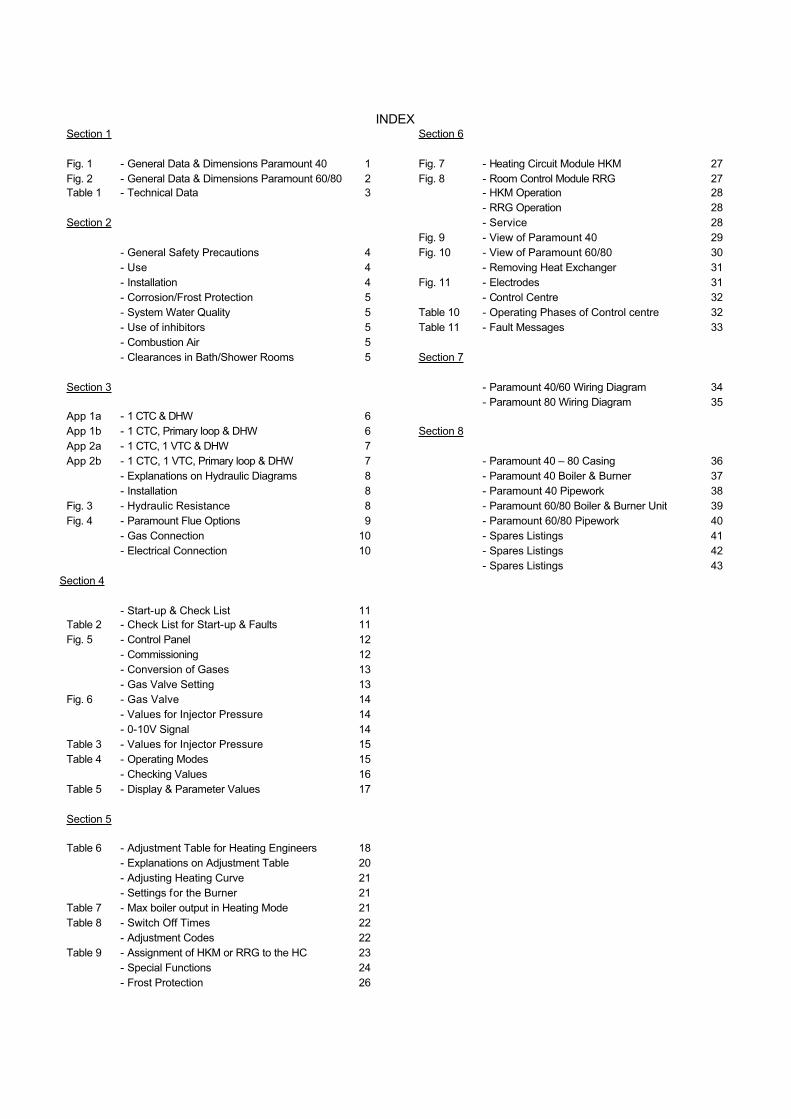
INDEXSection 1
Fig. 1 - General Data & Dimensions Paramount 40 1
Fig. 2 - General Data & Dimensions Paramount 60/80 2
Table 1 - Technical Data 3
Section 2
- General Safety Precautions 4
- Use 4
- Installation 4
- Corrosion/Frost Protection 5
- System Water Quality 5
- Use of inhibitors 5
- Combustion Air 5
- Clearances in Bath/Shower Rooms 5
Section 3
App 1a - 1 CTC & DHW 6
App 1b - 1 CTC, Primary loop & DHW 6
App 2a - 1 CTC, 1 VTC & DHW 7
App 2b - 1 CTC, 1 VTC, Primary loop & DHW 7
- Explanations on Hydraulic Diagrams 8
- Installation 8
Fig. 3 - Hydraulic Resistance 8
Fig. 4 - Paramount Flue Options 9
- Gas Connection 10
- Electrical Connection 10
Section 4
- Start-up & Check List 11
Table 2 - Check List for Start-up & Faults 11
Fig. 5 - Control Panel 12
- Commissioning 12
- Conversion of Gases 13
- Gas Valve Setting 13
Fig. 6 - Gas Valve 14
- Values for Injector Pressure 14
- 0-10V Signal 14
Table 3 - Values for Injector Pressure 15
Table 4 - Operating Modes 15
- Checking Values 16
Table 5 - Display & Parameter Values 17
Section 5
Table 6 - Adjustment Table for Heating Engineers 18
- Explanations on Adjustment Table 20
- Adjusting Heating Curve 21
- Settings for the Burner 21
Table 7 - Max boiler output in Heating Mode 21
Table 8 - Switch Off Times 22
- Adjustment Codes 22
Table 9 - Assignment of HKM or RRG to the HC 23
- Special Functions 24
- Frost Protection 26
Section 6
Fig. 7 - Heating Circuit Module HKM 27
Fig. 8 - Room Control Module RRG 27
- HKM Operation 28
- RRG Operation 28
- Service 28
Fig. 9 - View of Paramount 40 29
Fig. 10 - View of Paramount 60/80 30
- Removing Heat Exchanger 31
Fig. 11 - Electrodes 31
- Control Centre 32
Table 10 - Operating Phases of Control centre 32
Table 11 - Fault Messages 33
Section 7
- Paramount 40/60 Wiring Diagram 34
- Paramount 80 Wiring Diagram 35
Section 8
- Paramount 40 – 80 Casing 36
- Paramount 40 Boiler & Burner 37
- Paramount 40 Pipework 38
- Paramount 60/80 Boiler & Burner Unit 39
- Paramount 60/80 Pipework 40
- Spares Listings 41
- Spares Listings 42
- Spares Listings 43
POTTERTON COMMERCIAL PRODUCTS DIVISIONINSTALLATION, OPERATION AND MAINTENANCE MANUAL
SECTION 1
PARAMOUNT PAGE 1
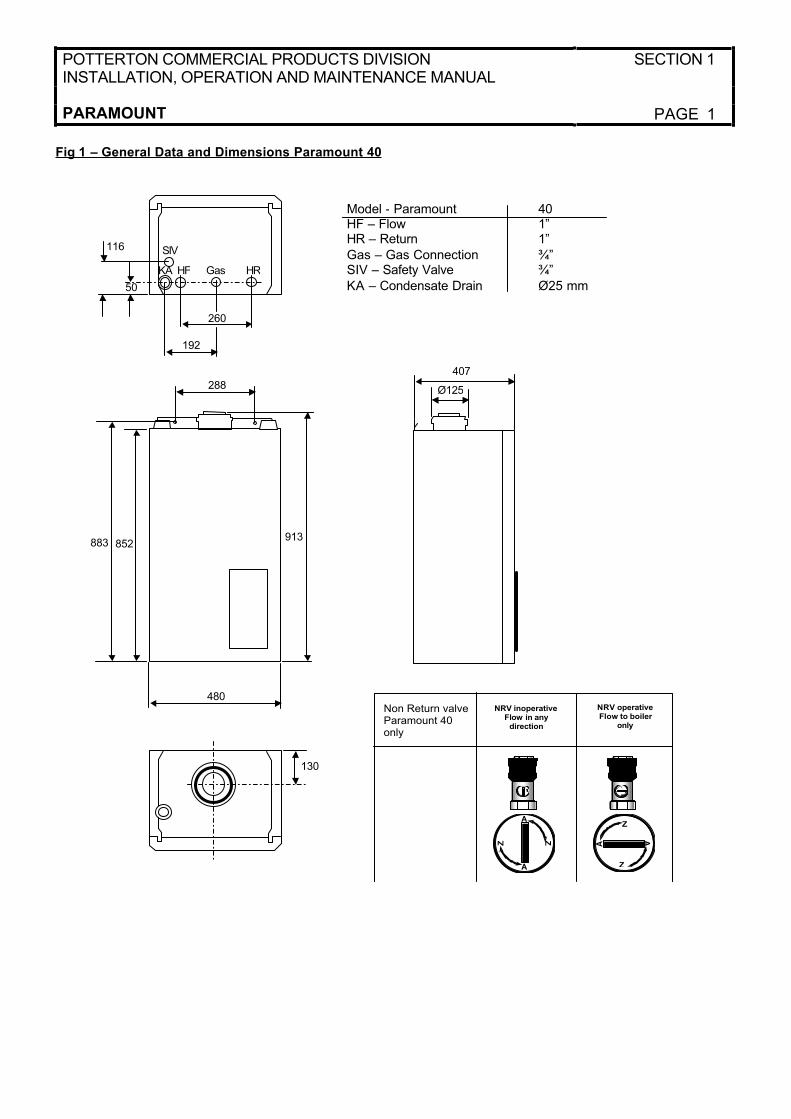
Fig 1 – General Data and Dimensions Paramount 40
288
913852
480
883
130
Ø125
407
Model - Paramount 40HF – Flow 1”HR – Return 1”
Gas – Gas Connection ¾”SIV – Safety Valve ¾”
KA – Condensate Drain Ø25 mm
Gas HRHF
50
260
192
SIV
KA
116
A
A
Z
Z A
A
Z
Z
Non Return valve Paramount 40 only
NRV inoperativeFlow in any direction
NRVoperativeFlow to boiler
only
A
A
Z
Z A
A
Z
Z
SECTION 1 POTTERTON COMMERCIAL PRODUCTS DIVISIONINSTALLATION, OPERATION AND MAINTENANCE MANUAL
PAGE 2 PARAMOUNT
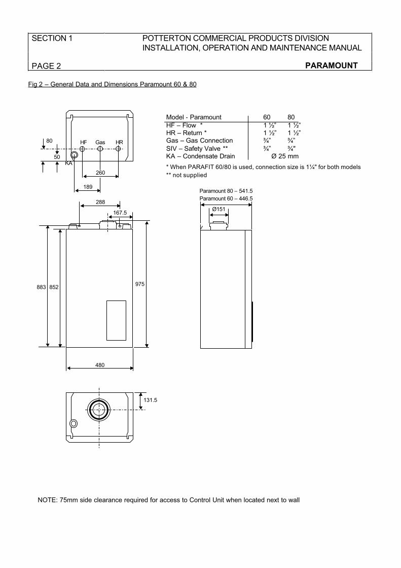
Fig 2 – General Data and Dimensions Paramount 60 & 80
131.5
Ø151
Paramount 80 – 541.5
Paramount 60 – 446.5
Model - Paramount 60 80
HF – Flow * 1 ½” 1 ½”HR – Return * 1 ½” 1 ½”Gas – Gas Connection ¾” ¾”
SIV – Safety Valve ** ¾” ¾"KA – Condensate Drain Ø 25 mm
* When PARAFIT 60/80 is used, connection size is 1¼" for both models
** not supplied
Gas HRHF
50
260
189
KA
80
NOTE: 75mm side clearance required for access to Control Unit when located next to wall
288
975852
480
883
167.5
POTTERTON COMMERCIAL PRODUCTS DIVISIONINSTALLATION, OPERATION AND MAINTENANCE MANUAL
SECTION 1
PARAMOUNT PAGE 3
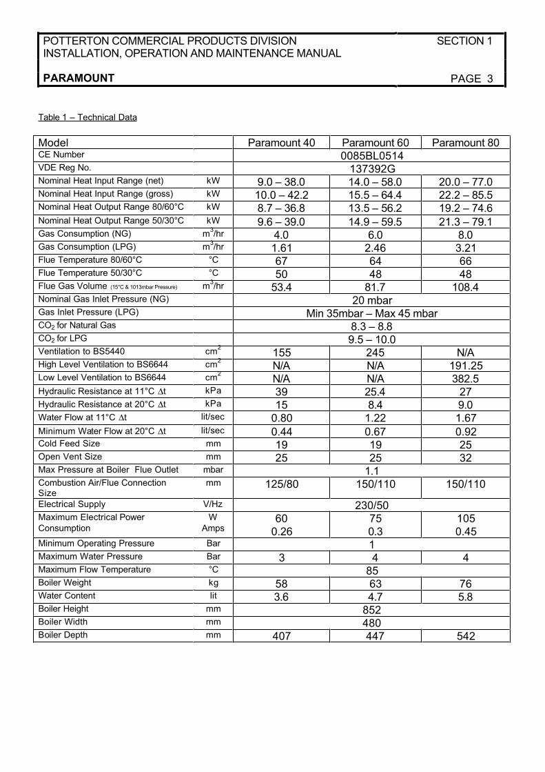
Table 1 – Technical Data
Model Paramount 40 Paramount 60 Paramount 80CE Number 0085BL0514VDE Reg No. 137392GNominal Heat Input Range (net) kW 9.0 – 38.0 14.0 – 58.0 20.0 – 77.0Nominal Heat Input Range (gross) kW 10.0 – 42.2 15.5 – 64.4 22.2 – 85.5Nominal Heat Output Range 80/60°C kW 8.7 – 36.8 13.5 – 56.2 19.2 – 74.6Nominal Heat Output Range 50/30°C kW 9.6 – 39.0 14.9 – 59.5 21.3 – 79.1Gas Consumption (NG) m
3/hr 4.0 6.0 8.0
Gas Consumption (LPG) m3/hr 1.61 2.46 3.21
Flue Temperature 80/60°C °C 67 64 66Flue Temperature 50/30°C °C 50 48 48Flue Gas Volume (15°C & 1013mbar Pressure) m
3/hr 53.4 81.7 108.4
Nominal Gas Inlet Pressure (NG) 20 mbarGas Inlet Pressure (LPG) Min 35mbar – Max 45 mbarCO2 for Natural Gas 8.3 – 8.8CO2 for LPG 9.5 – 10.0Ventilation to BS5440 cm
2155 245 N/A
High Level Ventilation to BS6644 cm2
N/A N/A 191.25Low Level Ventilation to BS6644 cm
2N/A N/A 382.5
Hydraulic Resistance at 11°C ∆t kPa 39 25.4 27Hydraulic Resistance at 20°C ∆t kPa 15 8.4 9.0Water Flow at 11°C ∆t lit/sec 0.80 1.22 1.67Minimum Water Flow at 20°C ∆t lit/sec 0.44 0.67 0.92Cold Feed Size mm 19 19 25Open Vent Size mm 25 25 32Max Pressure at Boiler Flue Outlet mbar 1.1Combustion Air/Flue Connection Size
mm 125/80 150/110 150/110
Electrical Supply V/Hz 230/50Maximum Electrical Power
Consumption
W
Amps60
0.26750.3
1050.45
Minimum Operating Pressure Bar 1Maximum Water Pressure Bar 3 4 4Maximum Flow Temperature °C 85Boiler Weight kg 58 63 76Water Content lit 3.6 4.7 5.8Boiler Height mm 852Boiler Width mm 480Boiler Depth mm 407 447 542
SECTION 2 POTTERTON COMMERCIAL PRODUCTS DIVISIONINSTALLATION, OPERATION AND MAINTENANCE MANUAL
PAGE 4 PARAMOUNT
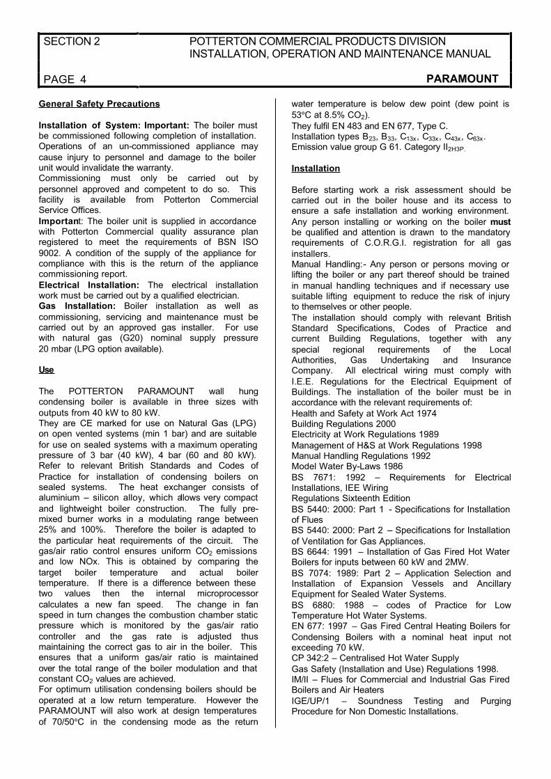
General Safety Precautions
Installation of System:Important:The boiler must be commissioned following completion of installation.Operations of an un-commissioned appliance may
cause injury to personnel and damage to the boiler unit would invalidate the warranty.Commissioning must only be carried out by
personnel approved and competent to do so. This facility is available from Potterton CommercialService Offices.
Important: The boiler unit is supplied in accordance with Potterton Commercial quality assurance planregistered to meet the requirements of BSN ISO
9002. A condition of the supply of the appliance for compliance with this is the return of the appliancecommissioning report.
Electrical Installation: The electrical installationwork must be carried out by a qualified electrician.Gas Installation: Boiler installation as well as
commissioning, servicing and maintenance must becarried out by an approved gas installer. For usewith natural gas (G20) nominal supply pressure
20 mbar (LPG option available).
Use
The POTTERTON PARAMOUNT wall hungcondensing boiler is available in three sizes with
outputs from 40 kW to 80 kW.They are CE marked for use on Natural Gas (LPG) on open vented systems (min 1 bar) and are suitable
for use on sealed systems with a maximum operating pressure of 3 bar (40 kW), 4 bar (60 and 80 kW). Refer to relevant British Standards and Codes of
Practice for installation of condensing boilers onsealed systems. The heat exchanger consists ofaluminium – silicon alloy, which allows very compact
and lightweight boiler construction. The fully pre-mixed burner works in a modulating range between25% and 100%. Therefore the boiler is adapted to
the particular heat requirements of the circuit. Thegas/air ratio control ensures uniform CO2 emissions and low NOx. This is obtained by comparing the
target boiler temperature and actual boilertemperature. If there is a difference between these two values then the internal microprocessor
calculates a new fan speed. The change in fanspeed in turn changes the combustion chamber static pressure which is monitored by the gas/air ratio
controller and the gas rate is adjusted thusmaintaining the correct gas to air in the boiler. This ensures that a uniform gas/air ratio is maintained
over the total range of the boiler modulation and that constant CO2 values are achieved.For optimum utilisation condensing boilers should be
operated at a low return temperature. However thePARAMOUNT will also work at design temperatures
of 70/50°C in the condensing mode as the return
water temperature is below dew point (dew point is
53°C at 8.5% CO2).
They fulfil EN 483 and EN 677, Type C.Installation types B23, B33, C13x, C33x, C43x, C63x.Emission value group G 61. Category II2H3P.
Installation
Before starting work a risk assessment should becarried out in the boiler house and its access toensure a safe installation and working environment.
Any person installing or working on the boiler mustbe qualified and attention is drawn to the mandatory requirements of C.O.R.G.I. registration for all gas
installers.Manual Handling:- Any person or persons moving or lifting the boiler or any part thereof should be trained
in manual handling techniques and if necessary use suitable lifting equipment to reduce the risk of injury to themselves or other people.
The installation should comply with relevant BritishStandard Specifications, Codes of Practice andcurrent Building Regulations, together with any
special regional requirements of the LocalAuthorities, Gas Undertaking and InsuranceCompany. All electrical wiring must comply with
I.E.E. Regulations for the Electrical Equipment ofBuildings. The installation of the boiler must be inaccordance with the relevant requirements of:
Health and Safety at Work Act 1974Building Regulations 2000Electricity at Work Regulations 1989
Management of H&S at Work Regulations 1998Manual Handling Regulations 1992Model Water By-Laws 1986
BS 7671: 1992 – Requirements for ElectricalInstallations, IEE WiringRegulations Sixteenth Edition
BS 5440: 2000: Part 1 - Specifications for Installation of FluesBS 5440: 2000: Part 2 – Specifications for Installation
of Ventilation for Gas Appliances.BS 6644: 1991 – Installation of Gas Fired Hot Water Boilers for inputs between 60 kW and 2MW.
BS 7074: 1989: Part 2 – Application Selection andInstallation of Expansion Vessels and AncillaryEquipment for Sealed Water Systems.
BS 6880: 1988 – codes of Practice for LowTemperature Hot Water Systems.EN 677: 1997 – Gas Fired Central Heating Boilers for
Condensing Boilers with a nominal heat input notexceeding 70 kW.CP 342:2 – Centralised Hot Water Supply
Gas Safety (Installation and Use) Regulations 1998.IM/II – Flues for Commercial and Industrial Gas Fired Boilers and Air Heaters
IGE/UP/1 – Soundness Testing and PurgingProcedure for Non Domestic Installations.

POTTERTON COMMERCIAL PRODUCTS DIVISIONINSTALLATION, OPERATION AND MAINTENANCE MANUAL
SECTION 2
PARAMOUNT PAGE 5
IGE/UP/2 – Gas Installation Pipework, Boosters and Compressors for Industrial and Commercial
Premises.Manufacturer's notes must not be taken in any way as over-riding statutory obligations
C.E Approvals: The CE approval symbol means that the PARAMOUNT fulfils the basic requirements of
the Gas Equipment Directive 90/396/EEC, the LowVoltage Directive 73/23/EEC as well as Directive89/336/EEC (Electromagnetic Compatibility EMC) of
the Council for Unification of Legal Regulations of the Member Countries. The PARAMOUNT boiler fulfils the basic requirements of the Boiler Efficiency
Directive 92/43/EEC for condensing boilers.
Corrosion Protection/Frost Protection
The combustion air must be free of corrosivesubstances – particularly vapours containing fluoride
and chloride such as are contained in solvents and cleaning agents, propulsion gases etc. When boilers are connected to under floor heating systems with
plastic piping, which is not impermeable to oxygen, heat exchangers must be used to separate thesystems.
System W ater Quality
To ensure the boiler heat exchanger remains in good condition it is essential to condition and monitor the system water to the following criteria:
Water hardness: if the system fill water has a
hardness in excess of 250 mg/l (17.5°Clark) thewater should be softened prior to filling the system to
ensure that excessive scaling does not occur within the heat exchanger.Water acidity: the system fill water should have a pH
value between 7 – 8.3 to ensure corrosion of the heat exchanger does not occur.Copper ions: the copper content of the system water
should be less than 0.05 mg/l. If large quantities of copper are present red and black copper oxide Cu2Oand CuO and grey/green copper carbonate, CuCo2
will be produced. Copper will corrode any iron and aluminium within the system. A special watertreatment company should be consulted if in doubt.
Use of Inhibitors
If a requirement for inhibitors exists ensure that the pH value of the heating water does not increase toabove a value of 8.3 pH. Also observe specifications
of additive supplier. When using tap water withhardness range above 3 as well as with heatingsystems with large water volumes, a decision should
be made individually regarding the use of hardness stabilising agents. Recommendations can beobtained from POTTERTON.
Combustion Air
For conventional flue operation of the PARAMOUNT, ensure that the installation room has a sufficiently
dimensioned opening for combustion air. Inform the operator of the system that it is not permissible toobstruct or plug the opening and that it is necessary
to keep the connection fitting for the combustion air at the top of the PARAMOUNT free from obstacles.Clean Combustion Air: Ensure that the
PARAMOUNT is installed only in rooms with cleancombustion air. Ensure that pollen or similar cannot penetrate through the inlet openings into the inside of
the equipment under any circumstances!
PARAMOUNT in Loft Space: If the PARAMOUNT is
used as a loft centre, POTTERTON recommendsinstalling a water catch pan below the hot-water tank.
Operation in Shower Room: When installed inshower rooms, ensure that the following conditions are fulfilled:
1. Balanced flue operation
2. To maintain protective system IPX4D- Operate only with room control module RRG in living area or
- Operate with heating circuit module HKM(without EMS timer) with DSU timer in livingareas.
3. All incoming and outgoing electric cablesmust be installed through and restrained by
pull relief glands. Tighten the glands tightlyso that water cannot get into the inside of the housing!
Clearances for Paramount in bath and shower rooms
The PARAMOUNT wall mounted boiler fulfils theprotection Standard IPX4D (protection range 2)according to VDE 0100, Part 701 and may be
0.6
2.4
ProtectiveZone 2
ProtectiveZone 3
0.6
2.4
ProtectiveZone 2
ProtectiveZone 3

SECTION 2 POTTERTON COMMERCIAL PRODUCTS DIVISIONINSTALLATION, OPERATION AND MAINTENANCE MANUAL
PAGE 6 PARAMOUNT
installed in protective zone 2 (see also note above"Operation in wet rooms"). In protection zone 1 and
2, only permanently installed lines are permissibleaccording to VDE 0100.
POTTERTON COMMERCIAL PRODUCTS DIVISIONINSTALLATION, OPERATION AND MAINTENANCE MANUAL
SECTION 3
PARAMOUNT PAGE 7
Applications and Installation Details
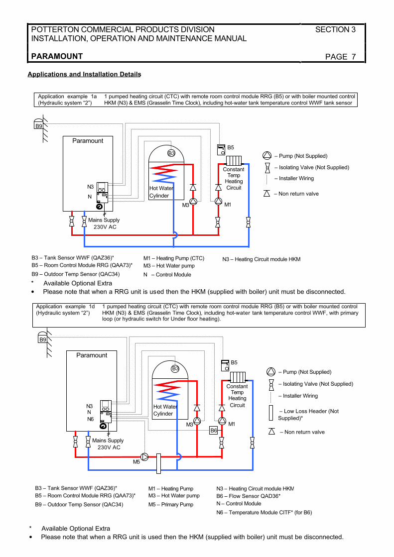
Application example 1a(Hydraulic system “2”)
1 pumped heating circuit (CTC) with remote room control module RRG (B5) or with boiler mounted controlHKM (N3) & EMS (Grasselin Time Clock), including hot-water tank temperature control WWF tank sensor
B3 – Tank Sensor WWF (QAZ36)*
B5 – Room Control Module RRG (QAA73)*
B9 – Outdoor Temp Sensor (QAC34)
M1 – Heating Pump (CTC)
M3 – Hot Water pump
N – Control Module
N3 – Heating Circuit module HKM
* Available Optional Extra
• Please note that when a RRG unit is used then the HKM (supplied with boiler) unit must be disconnected.
Application example 1d(Hydraulic system “2”)
1 pumped heating circuit (CTC) with remote room control module RRG (B5) or with boiler mounted controlHKM (N3) & EMS (Grasselin Time Clock), including hot-water tank temperature control WWF, with primary loop (or hydraulic switch for Under floor heating).
B3 – Tank Sensor WWF (QAZ36)*
B5 – Room Control Module RRG (QAA73)*
B9 – Outdoor Temp Sensor (QAC34)
M1 – Heating Pump
M3 – Hot Water pump
M5 – Primary Pump
N3 – Heating Circuit module HKM
B6 – Flow Sensor QAD36*
N – Control Module
N6 – Temperature Module CITF* (for B6)
* Available Optional Extra
• Please note that when a RRG unit is used then the HKM (supplied with boiler) unit must be disconnected.
B5
M3 M1
ConstantTemp
HeatingCircuit
N
N3
Paramount
– Pump (Not Supplied)
– Isolating Valve (Not Supplied)
– Installer Wiring
Hot Water
Cylinder
B3
Mains Supply
230V AC
B9
– Non return valve
B5
M3 M1
ConstantTemp
Heating
Circuit
N
N6
N3
Paramount
– Pump (Not Supplied)
– Isolating Valve (Not Supplied)
– Installer Wiring
Hot Water
Cylinder
B3
Mains Supply
230V AC
B9
B6
M5
– Low Loss Header (Not
Supplied)*
– Non return valve
SECTION 3 POTTERTON COMMERCIAL PRODUCTS DIVISIONINSTALLATION, OPERATION AND MAINTENANCE MANUAL
PAGE 8 PARAMOUNT
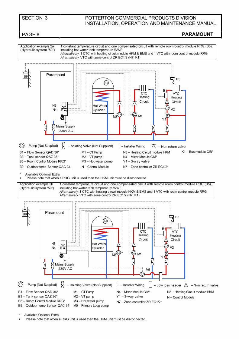
Application example 2a(Hydraulic system “50”)
1 constant temperature circuit and one compensated circuit with remote room control module RRG (B5), including hot-water tank temperature WWF Alternatively: 1 CTC with heating circuit module HKM & EMS and 1 VTC with room control module RRGAlternatively: VTC with zone control ZR EC1/2 (N7, K1)
B1 – Flow Sensor QAD 36*
B3 – Tank sensor QAZ 36*
B5 – Room Control Module RRG*
B9 – Outdoor temp Sensor QAC 34
M1 – CT Pump
M2 – VT pump
M3 – Hot water pump
N – Control Module
K1 – Bus module CIB*
* Available Optional Extra• Please note that when a RRG unit is used then the HKM unit must be disconnected.
N3 – Heating Circuit module HKM
N4 – Mixer Module CIM*
Y1 – 3-way valve
N7 – Zone controller ZR EC1/2*
B5
M3 M1
CTCHeating
Circuit
N4
N3
Paramount
– Pump (Not Supplied) – Isolating Valve (Not Supplied) – Installer Wiring
Hot Water
Cylinder
B3
Mains Supply
230V AC
B9
B1
M2
VTCHeating
Circuit
Y1
Application example 2b(Hydraulic system “50”)
1 constant temperature circuit and one compensated circuit with remote room control module RRG (B5), including hot-water tank temperature WWF Alternatively: 1 CTC with heating circuit module HKM & EMS and 1 VTC with room control module RRGAlternatively: VTC with zone control ZR EC1/2 (N7, K1)
B5
M3 M1
CTCHeating
Circuit
N4
N3
Paramount
Hot Water
Cylinder
B3
Mains Supply
230V AC
B9
B1
M2
VTCHeating
Circuit
Y1
M5
B1 – Flow Sensor QAD 36*
B3 – Tank sensor QAZ 36*
B5 – Room Control Module RRG*
B9 – Outdoor temp Sensor QAC 34
M1 – CT Pump
M2 – VT pump
M3 – Hot water pump
M5 – Primary Loop pump
N3 – Heating Circuit module HKM
N – Control Module
* Available Optional Extra
• Please note that when a RRG unit is used then the HKM unit must be disconnected.
N4 – Mixer Module CIM*
Y1 – 3-way valve
N7 – Zone controller ZR EC1/2*
– Non return valve
– Pump (Not Supplied) – Isolating Valve (Not Supplied) – Installer Wiring – Low loss header – Non return valve
POTTERTON COMMERCIAL PRODUCTS DIVISIONINSTALLATION, OPERATION AND MAINTENANCE MANUAL
SECTION 3
PARAMOUNT PAGE 9
Explanations on Hydraulic Diagrams
For certain applications it is necessary to set theboiler controller to the correct hydraulic setting, below are the settings required.
Application example 1a:- Hydraulic system “2” (Factory Preset)
Application example 1d:- Hydraulic system “2” (Factory Preset)
- Set parameter 618 to 6 - Connect flow sensor B6 to the temperature
module CITF.
Header pump M5 (exit M5):- Set Parameter 615 to 9 and parameter 632 as
follows: b2 = 1, b3 = 1
- Connect primary loop pump to exit M5 Connect pump for CTC to M1
Application example 2a:
- Set hydraulic system to “50” ⇒ Set Parameter 552 to 50
Alternatively, 1 mixer circuit with zone control (M5)
- Set hydraulic system to “66” ⇒ Set Parameter 552 to 66
Application example 2b:
- Set hydraulic system to “50” ⇒ Set Parameter
552 to 50Header pump M5 (exit M5):- Set parameter No 615 to 9 and parameter 632,
b1 = 1
Special Applications
For other applications please contact the PottertonCommercial Technical department who will be
pleased to discuss any requirements you have.
INSTALLATION
Connecting Heating Circuit: Connect heating circuitto boiler flow and boiler return with flat sealing
threaded fittings. Welded or brazed connection is not permissible (guarantee void). We recommendinstallation of a filter in the heating return. On old
systems, the entire heating system should be flushed thoroughly before installation. Install isolation valves in flow and return.
Safety Valve: Ensure that the blow-out pipe for thesafety valve is installed so that a pressure increase,
when the safety valve actuates, is not possible. The pipe should not lead outside, the outlet must be free and observable. It must be possible for any heating
water escaping to drain without danger e.g. through a trap.
Sealing and Filling the System: Fill the heatingsystem through the return on the PARAMOUNT. For
this purpose, open the non-return valve(PARAMOUNT 40 ONLY, SEE Fig.1) after filling,move the non-return valve back into the operating
position. Check for leakage (max. water test pressure 3 bar).
Condensate: It is only permissible to drain thecondensate directly into a domestic sewer systemwhen the system consists of corrosion-resistant
materials (e.g. PP pipe, stoneware etc.). If this is not applicable, it is possible install the POTTERTONcondensate treatment tank. It must be possible for
the condensate to drain freely into a funnel. A trap must be installed between the funnel and sewersystem. Root the condensate hose from the
PARAMOUNT out of the boiler on the left, next to the heating flow.
Caution: Before commissioning, fill the condensatedrain in the boiler with water. For this purpose, fill 0.25L of water into the flue fitting before installing the
flue pipe.
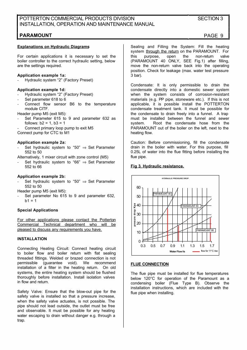
Fig 3. Hydraulic resistance.
FLUE CONNECTION
The flue pipe must be installed for flue temperatures
below 120°C for operation of the Paramount as acondensing boiler (Flue Type B). Observe theinstallation instructions, which are included with the
flue pipe when installing.
HYDRAULIC PRESSURE DROP
0
10
20
30
40
50
60
0.3 0.5 0.7 0.9 1.1 1.3 1.5 1.7
Water Flow l/s
pre
su
re d
rop
Kp
a
PARAMOUNT 40
PARAMOUNT 60
PARAMOUNT 80
flow for 11°C rise
SECTION 3 POTTERTON COMMERCIAL PRODUCTS DIVISIONINSTALLATION, OPERATION AND MAINTENANCE MANUAL
PAGE 10 PARAMOUNT
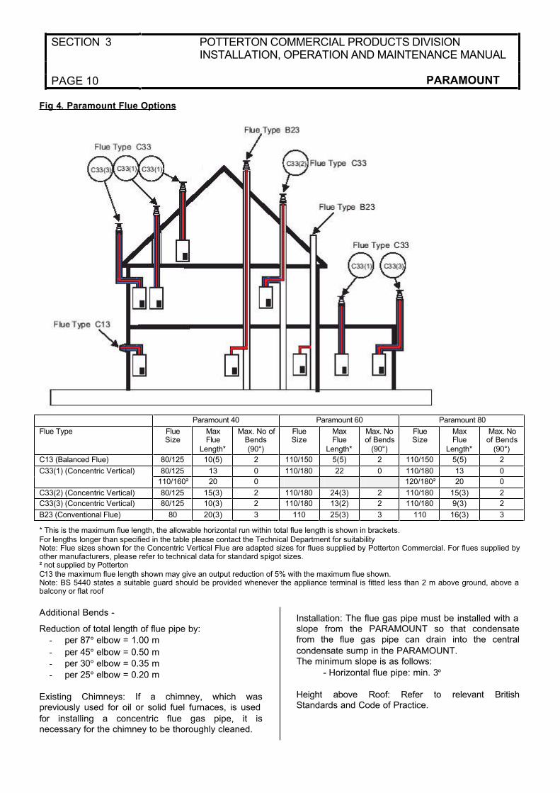
Fig 4. Paramount Flue Options
Paramount 40 Paramount 60 Paramount 80
Flue Type FlueSize
MaxFlue
Length*
Max. No of Bends(90°)
FlueSize
MaxFlue
Length*
Max. No of Bends
(90°)
FlueSize
MaxFlue
Length*
Max. No of Bends
(90°)
C13 (Balanced Flue) 80/125 10(5) 2 110/150 5(5) 2 110/150 5(5) 2
80/125 13 0 110/180 22 0 110/180 13 0C33(1) (Concentric Vertical)
110/160² 20 0 120/180² 20 0
C33(2) (Concentric Vertical) 80/125 15(3) 2 110/180 24(3) 2 110/180 15(3) 2
C33(3) (Concentric Vertical) 80/125 10(3) 2 110/180 13(2) 2 110/180 9(3) 2
B23 (Conventional Flue) 80 20(3) 3 110 25(3) 3 110 16(3) 3
* This is the maximum flue length, the allowable horizontal run within total flue length is shown in brackets.For lengths longer than specified in the table please contact the Technical Department for suitabilityNote: Flue sizes shown for the Concentric Vertical Flue are adapted sizes for flues supplied by Potterton Commercial. For flues supplied by other manufacturers, please refer to technical data for standard spigot sizes.² not supplied by PottertonC13 the maximum flue length shown may give an output reduction of 5% with the maximum flue shown.Note: BS 5440 states a suitable guard should be provided whenever the appliance terminal is fitted less than 2 m above ground, above a balcony or flat roof
Additional Bends -
Reduction of total length of flue pipe by:
- per 87° elbow = 1.00 m
- per 45° elbow = 0.50 m
- per 30° elbow = 0.35 m
- per 25° elbow = 0.20 m
Existing Chimneys: If a chimney, which waspreviously used for oil or solid fuel furnaces, is used
for installing a concentric flue gas pipe, it isnecessary for the chimney to be thoroughly cleaned.
Installation: The flue gas pipe must be installed with a slope from the PARAMOUNT so that condensatefrom the flue gas pipe can drain into the central
condensate sump in the PARAMOUNT.The minimum slope is as follows:
- Horizontal flue pipe: min. 3°
Height above Roof: Refer to relevant BritishStandards and Code of Practice.
POTTERTON COMMERCIAL PRODUCTS DIVISIONINSTALLATION, OPERATION AND MAINTENANCE MANUAL
SECTION 3
PARAMOUNT PAGE 11
GAS CONNECTION
Factory Settings: The PARAMOUNT is set at the factory to a maximum heat load either for- G20 gas (natural gas type H, Wobbe index
WoN = 15.0 k Wh/m3) or
- optional extra PARAKLPG.
LPG Version: In case error message “133” appears Table 13, Page 54) the cause can be gas errormessage “133” insufficiency. In this case check the
LPG gas tank.
Supply Pressure: The supply pressure should be
between the following values:for natural gas - min. 17 mbar - max. 25 mbarfor LPG - nominal 37 mbar
The supply pressure should be read off as the flow pressure at the measuring point on the gas valve.
The PARAMOUNT should never be put intooperation at supply pressures outside the specifiedrange. Advise the gas company if insufficient
pressure available.
CO2 Content: During initial operation and regular
maintenance of the PARAMOUNT measure the CO2
content in the flue gas.
The CO2 content should be as follows:with natural gas: between 8.3% and 8.8%with LPG: between 9.5% and 10.0%
Exceptionally high CO2 values can lead to incorrect combustion (high CO values) and damage to the
burner. CO2 values which are too low can lead toignition problems. The CO2 value can be set byadjusting the gas pressure on the gas valve.
ELECTRICAL CONNECTION
Electrical Connection (General): Supply power 1/N/PEAC230 V + 10% - 15%, 50 Hz max. 140 W, fuse: 6A
Observe the IEE and local regulationsThe electrical connection should be made so that the polarity cannot be mixed up and is connected
correctly.
Electrical Supply: A 230V 50 Hz AC single phase
electrical supply is required. The incoming mainssupply should be terminated via a double pole fused isolator to the boiler, see wiring diagram for wiring
details. A fused supply is required. The boiler has a 6.3A internal fuse.
Cable Lengths: Cables for sensors of bus cables do not carry mains voltage, but low voltage. Theyshould not be put parallel to mains wires (this may
lead to disturbances) otherwise screen cable should be used.
Maximum lengths of wires for all sensors:- Copper wires up to 20 m 0.6 mm dia
- Copper wires up to 80 m 1 mm2
- Copper wires up to 120m 1.5 mm2
Inside the boiler, all cables have to be laid in the
cable clips and when led put of the boiler, fixed in the strain clamps.
Circulation Pumps: The electrical permitted load for each pump output is INmax = 1A.If pump has higher load a contactor should be used.
Fuses: Fused in control unit:F1 – T 6.3 H 250; line
Connecting Sensors/Components: Observe wiringdiagram. Install and connect optional extras
according to the instructions enclosed. Completesupply power connection. Check protective earth.Connect optional extras according to wiring diagram.
Outdoor Temperatures Sensor (Supplied): Theoutdoor temperature sensor is included in a separate
package. Connect according to wiring diagram.
Replacing Wires: All connection wires apart from
the mains connection must be replaced whennecessary with correct connection wiring. Whenreplacing the mains cable, only cables Type H05VV-
F complying with BS6500.
Contact Protection: After opening the
PARAMOUNT, refasten, the covering parts to bescrewed on with the appropriate screws to ensurethat no one can touch conductive parts on the inside
SECTION 4 POTTERTON COMMERCIAL PRODUCTS DIVISIONINSTALLATION , OPERATION AND MAINTENANCE MANUAL
PAGE 12 PARAMOUNT
START-UP AND CHECK LIST
Start Up: Before commissioning the boiler read theoperating instructions and observe the “check list” in the table below!
Initial operation should be accomplished by a heating engineer who advised the user regarding handlingand operation of the unit and its safety equipment
and submits to the operator the operating instructions for the heating system.
Important Notes: These instructions should always
be kept in the boiler room where they are readilyavailable.For optimum fault free operation:
- set hydraulic system correctly (parameter 552)- refer to wiring diagram (page 8)- set the suitable heating curve, room control
RRG is used or a HKM with a room thermostat.
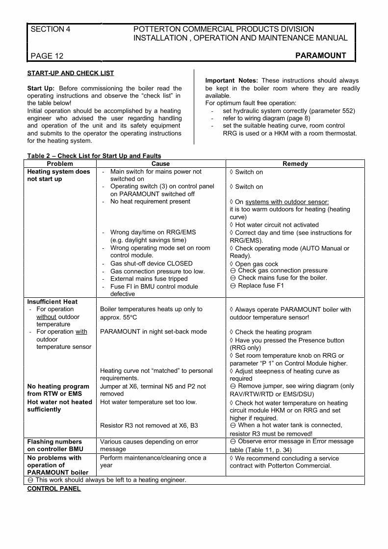
Table 2 – Check List for Start Up and Faults
Problem Cause Remedy
Heating system does not start up
- Main switch for mains power not switched on
◊ Switch on
- Operating switch (3) on control panel
on PARAMOUNT switched off◊ Switch on
- No heat requirement present ◊ On systems with outdoor sensor:it is too warm outdoors for heating (heating
curve)
◊ Hot water circuit not activated- Wrong day/time on RRG/EMS
(e.g. daylight savings time)◊ Correct day and time (see instructions for
RRG/EMS).- Wrong operating mode set on room
control module.◊ Check operating mode (AUTO Manual or Ready).
- Gas shut-off device CLOSED ◊ Open gas cock- Gas connection pressure too low. y Check gas connection pressure
- External mains fuse tripped
- Fuse FI in BMU control module defective
y Check mains fuse for the boiler.
y Replace fuse F1
Insufficient Heat- For operation
without outdoor temperature
Boiler temperatures heats up only to
approx. 55°C◊ Always operate PARAMOUNT boiler with
outdoor temperature sensor!
- For operation with
outdoortemperature sensor
PARAMOUNT in night set-back mode ◊ Check the heating program
◊ Have you pressed the Presence button (RRG only)
◊ Set room temperature knob on RRG or
parameter “P 1” on Control Module higher.Heating curve not “matched” to personal requirements.
◊ Adjust steepness of heating curve as required
No heating program from RTW or EMS
Jumper at X6, terminal N5 and P2 not removed
y Remove jumper, see wiring diagram (only
RAV/RTW/RTD or EMS/DSU)
Hot water not heated sufficiently
Hot water temperature set too low. ◊ Check hot water temperature on heating circuit module HKM or on RRG and set
higher if required.Resistor R3 not removed at X6, B3 y When a hot water tank is connected,
resistor R3 must be removed!
Flashing numbers on controller BMU
Various causes depending on error message
y Observe error message in Error message
table (Table 11, p. 34)
No problems with operation of PARAMOUNT boiler
Perform maintenance/cleaning once a year
◊ We recommend concluding a service contract with Potterton Commercial.
y This work should always be left to a heating engineer.
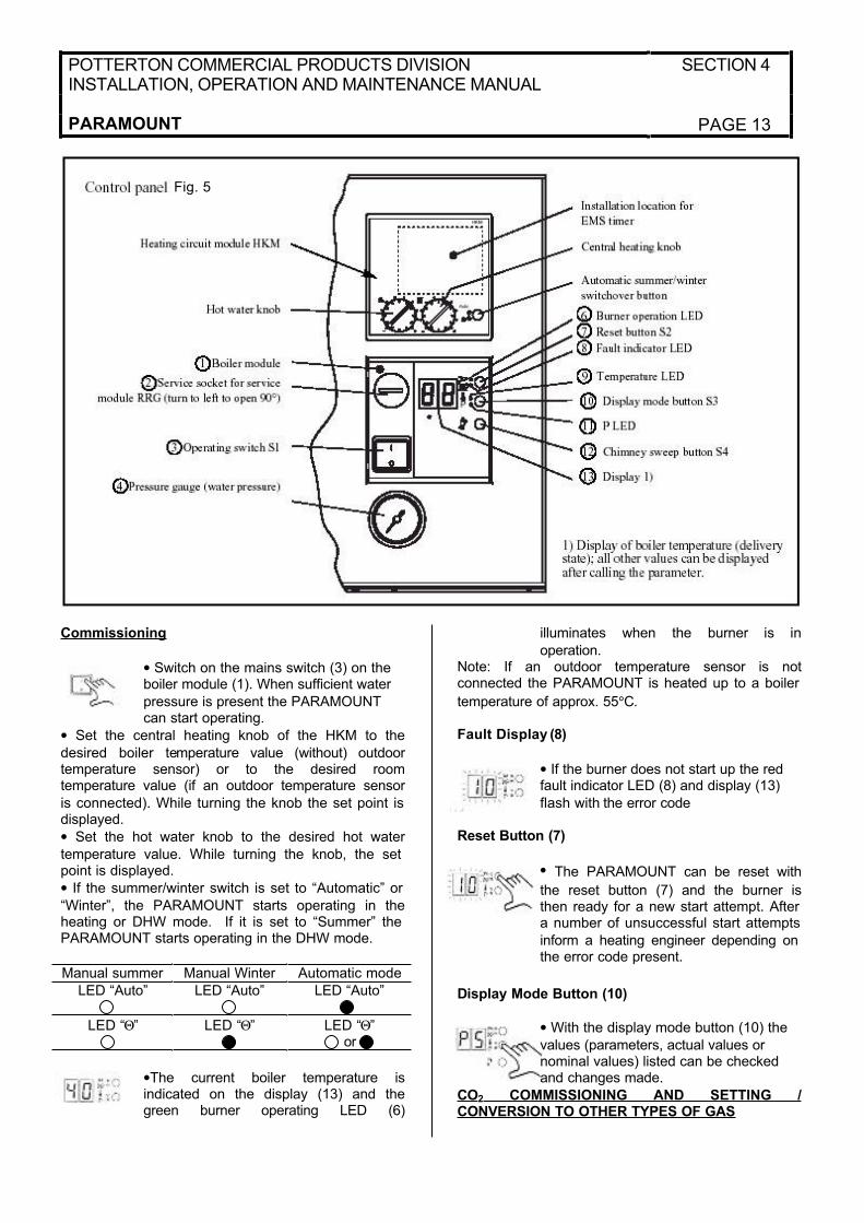
CONTROL PANEL
POTTERTON COMMERCIAL PRODUCTS DIVISIONINSTALLATION, OPERATION AND MAINTENANCE MANUAL
SECTION 4
PARAMOUNT PAGE 13
Commissioning
• Switch on the mains switch (3) on the boiler module (1). When sufficient water
pressure is present the PARAMOUNT can start operating.
• Set the central heating knob of the HKM to the
desired boiler temperature value (without) outdoortemperature sensor) or to the desired roomtemperature value (if an outdoor temperature sensor
is connected). While turning the knob the set point is displayed.
• Set the hot water knob to the desired hot water
temperature value. While turning the knob, the set point is displayed.
• If the summer/winter switch is set to “Automatic” or
“Winter”, the PARAMOUNT starts operating in theheating or DHW mode. If it is set to “Summer” the PARAMOUNT starts operating in the DHW mode.
Manual summer Manual Winter Automatic mode
LED “Auto” LED “Auto” LED “Auto”
LED “Θ” LED “Θ” LED “Θ”or
•The current boiler temperature isindicated on the display (13) and thegreen burner operating LED (6)
illuminates when the burner is in
operation.Note: If an outdoor temperature sensor is notconnected the PARAMOUNT is heated up to a boiler
temperature of approx. 55°C.
Fault Display (8)
• If the burner does not start up the red fault indicator LED (8) and display (13)
flash with the error code
Reset Button (7)
• The PARAMOUNT can be reset with
the reset button (7) and the burner isthen ready for a new start attempt. After a number of unsuccessful start attempts
inform a heating engineer depending on the error code present.
Display Mode Button (10)
• With the display mode button (10) the
values (parameters, actual values or nominal values) listed can be checked and changes made.
CO2 COMMISSIONING AND SETTING /CONVERSION TO OTHER TYPES OF GAS
Fig. 5
SECTION 4 POTTERTON COMMERCIAL PRODUCTS DIVISIONINSTALLATION , OPERATION AND MAINTENANCE MANUAL
PAGE 14 PARAMOUNT
Gas/Air Ratio Control: With the gas/air ratio control for the PARAMOUNT, the gas supply is adapted to
the air supply, which is factory set. Adjustmentshould be accomplished at maximum and minimum nominal heat input, called full load and minimum load
below.
Changing over from LPG to Natural Gas or Vice
Versa: The type of gas for the PARAMOUNT boiler should be changed only by an authorised gasinstaller. To convert, replace the gas injector (Table
5) and adjust the CO2 content by adjusting theinjector pressure on the gas valve. The CO2 content should be between the following values at full load as
well as at minimum load:
CO2 content (natural gas): 8.3% - 8.8%
CO2 content (LPG) 9.5% - 10.0%
Put the sticker with the gas (provided with the kit) on
the gas pipe.
Adjusting and Checking the Values: Operate the
PARAMOUNT in the controller stop mode to adjust and CO2 values.
Controller Stop Mode (manual adjustment ofburner capacity): In the controller stop mode, theburner can be set to all loads within the modulation
range. Check the adjustment of the CO2 values at full load and minimum load. Activate the controllerstop mode on the boiler module (1)
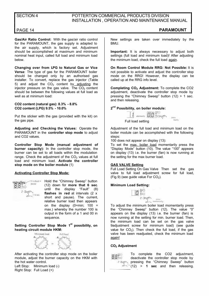
Activating Controller Stop Mode:
Hold the “Chimney Sweep” button (12) down for more that 6 sec.until the display “Fault” (8)
flashes in red at intervals (2 x short and pause). The current,relative burner load then appears
on the display (0=min; 100 =max.) whereby the number 100 is output in the form of a 1 and 00 in
sequence.
Setting Controller Stop Mode 1st
possibility, on
heating circuit module HKM:
After activating the controller stop mode on the boiler module, adjust the burner capacity on the HKM with the hot water control.
Left Stop: Minimum load (-)Right Stop: Full Load (+)
New settings are taken over immediately by theBMU.
Important: It is always necessary to adjust bothsettings (full load and minimum load)! After adjusting
the minimum load, check the full load again.
On Room Control Module RRG: Not Possible: It is
not possible to activate and adjust the controller stop mode on the RRG! However, the display can becalled up at the RRG info level.
Completing CO2 Adjustment: To complete the CO2 adjustment, deactivate the controller stop mode by
pressing the “Chimney Sweep” button (12) > 1 sec. and then releasing.
2nd
Possibility, on boiler module:
Adjustment of the full load and minimum load on the
boiler module can be accomplished with the following steps:100 does not appear on display (13):
To set the max. boiler load momentarily press the“Display Mode” button (10). The value “100” appears on display (13) i.e. the burner (fan) is now running at
the setting for the max burner load.
GAS VALVE Setting
Full Load Setting On Gas Valve Then set the gasvalve to full load adjustment screw for full load,(Fig.9) (see guide value For CO2).
Minimum Load Setting:
To adjust the minimum boiler load momentarily press the “Chimney Sweep” button (12). The value “0”appears on the display (13) i.e. the burner (fan) is
now running at the setting for min. burner load. Then, the minimum load can be set on the gas valve9adjustment screw for minimum load) (see guide
value for CO2). Then check the full load, if the gas valve has been readjusted, check the minimum load again!
CO2 Adjustment
To complete the CO2 adjustment,deactivate the controller stop mode by pressing the “Chimney Sweep” button
(12) > 1 sec and then releasing.
Full load setting

POTTERTON COMMERCIAL PRODUCTS DIVISIONINSTALLATION, OPERATION AND MAINTENANCE MANUAL
SECTION 4
PARAMOUNT PAGE 15
Fig. 6 gas valve (injector pressure settings can be made with 2.5 mm Allen key) (not provided)
Landis & Staefa Co. VDU (PARAMOUNT 40)
Adjustment screw forinjector pressure (full load)+ Clockwise: More gas- Anticlockwise: Less gas
Measuringfitting forinjectorpressure
Measuringfitting forsupplypressure
Adjustment screw for injector pressure (minimum load)+ Clockwise: More gas- Anticlockwise: Less gas
Kromschröder Co.CG 10… No.847 55 366(PARAMOUNT 60)
Measuring fitting forinjector pressure
Adjustment for injectorpressure (full load)+Anticlockwise: Moregas- Anticlockwise: Lessgas
Measuring fitting forsupply pressure
Adjustment screw for injector pressure (minimum load)+ Clockwise: More gas- Anticlockwise: Less gas
Fabr. Kromschröder CG 120 Ro1-Vt2WF1(PARAMOUNT 80)
Measuring fitting forinjector pressure
Adjustment screw for injector pressure (full load)+Clockwise: More gas- Anticlocwise: Less gas
Measuring fitting for
supply pressure
Adjustment screw forinjector pressure (minimumload)+ Clockwise: More gas- Anticlockwise: Less gas
GUIDE VALUES FOR INJECTOR PRESSURE
Guide Values for Gas Flow Rate Injector Pressure and CO2 Content: The values given in Table 3 are guide values. It is important that the gas quantity is
set via the injector pressure so that the CO2 value is within the specified values.
Boiler Control via 0 – 10V DC input signal (relay clip-in module CISP): The boiler is provided with an input for a 0-10V DC signal to control the boiler
temperature of the boiler output directly.- to activate this function, set param 618 to 4 or 5 (see parameter for details)
- For a proper use of this input, disconnect allexternal controls from the boiler (e.g. room control RRG) and set the heating curve to “___” (parameters
532 and 533 see parameter listings).
NOTE: If another relay clip-in is installed (e.g. CIR, CIST, CITF), the CISP must be taken out and
Parameter 618 must then be programmed accordingto the installation manual of the specific clip-inmodule.
SECTION 4 POTTERTON COMMERCIAL PRODUCTS DIVISIONINSTALLATION , OPERATION AND MAINTENANCE MANUAL
PAGE 16 PARAMOUNT
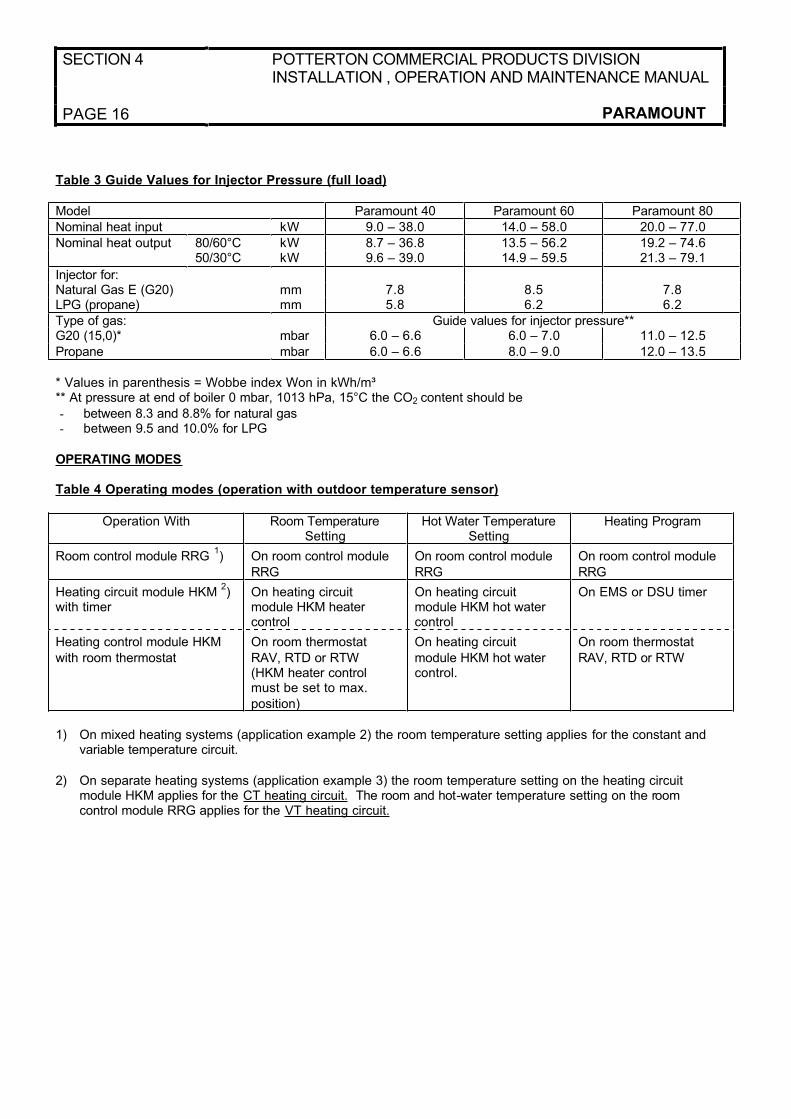
Table 3 Guide Values for Injector Pressure (full load)
Model Paramount 40 Paramount 60 Paramount 80
Nominal heat input kW 9.0 – 38.0 14.0 – 58.0 20.0 – 77.0
Nominal heat output 80/60°C kW 8.7 – 36.8 13.5 – 56.2 19.2 – 74.650/30°C kW 9.6 – 39.0 14.9 – 59.5 21.3 – 79.1
Injector for:Natural Gas E (G20) mm 7.8 8.5 7.8LPG (propane) mm 5.8 6.2 6.2
Type of gas: Guide values for injector pressure**G20 (15,0)* mbar 6.0 – 6.6 6.0 – 7.0 11.0 – 12.5
Propane mbar 6.0 – 6.6 8.0 – 9.0 12.0 – 13.5
* Values in parenthesis = Wobbe index Won in kWh/m³** At pressure at end of boiler 0 mbar, 1013 hPa, 15°C the CO2 content should be
- between 8.3 and 8.8% for natural gas- between 9.5 and 10.0% for LPG
OPERATING MODES
Table 4 Operating modes (operation with outdoor temperature sensor)
Operation With Room Temperature Setting
Hot Water Temperature Setting
Heating Program
Room control module RRG 1) On room control module
RRG
On room control module
RRG
On room control module
RRG
Heating circuit module HKM 2)
with timerOn heating circuit module HKM heater control
On heating circuit module HKM hot water control
On EMS or DSU timer
Heating control module HKM
with room thermostat
On room thermostat
RAV, RTD or RTW (HKM heater control must be set to max.
position)
On heating circuit
module HKM hot water control.
On room thermostat
RAV, RTD or RTW
1) On mixed heating systems (application example 2) the room temperature setting applies for the constant and variable temperature circuit.
2) On separate heating systems (application example 3) the room temperature setting on the heating circuit module HKM applies for the CT heating circuit. The room and hot-water temperature setting on the roomcontrol module RRG applies for the VT heating circuit.
POTTERTON COMMERCIAL PRODUCTS DIVISIONINSTALLATION, OPERATION AND MAINTENANCE MANUAL
SECTION 4
PARAMOUNT PAGE 17
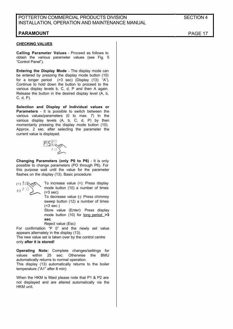
CHECKING VALUES
Calling Parameter Values - Proceed as follows to obtain the various parameter values (see Fig. 5“Control Panel”).
Entering the Display Mode - The display mode can be entered by pressing the display mode button (10)
for a longer period (>3 sec) (Display (13): “A”).Continue to hold down the button to proceed to the various display levels b, C, d, P and then A again.
Release the button in the desired display level (A, b, C, d, P).
Selection and Display of Individual values orParameters - It is possible to switch between thevarious values/parameters (0 to max. 7) In the
various display levels (A, b, C, d, P) by thenmomentarily pressing the display mode button (10). Approx. 2 sec. after selecting the parameter the
current value is displayed.
Changing Parameters (only P0 to P6) - It is only possible to change parameters (PO through P6). For this purpose wait until the value for the parameter
flashes on the display (13). Basic procedure:
To increase value (+): Press display
mode button (10) a number of times (<3 sec).To decrease value (-): Press chimney
sweep button (12) a number of times (<3 sec.)Store value (Enter): Press display
mode button (10) for long period >3sec.Reject value (Esc)
For confirmation “P 0” and the newly set valueappears alternately in the display (13).The new value set is taken over by the control centre
only after it is stored!
Operating Note: Complete changes/settings for
values within 25 sec. Otherwise the BMUautomatically returns to normal operation.This display (13) automatically returns to the boiler
temperature (“A1” after 8 min)
When the HKM is fitted please note that P1 & P2 are
not displayed and are altered automatically via theHKM unit.
(+)
(-)
SECTION 4 POTTERTON COMMERCIAL PRODUCTS DIVISIONINSTALLATION , OPERATION AND MAINTENANCE MANUAL
PAGE 18 PARAMOUNT
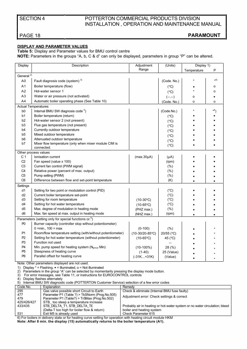
DISPLAY AND PARAMETER VALUESTable 5: Display and Parameter values for BMU control centre
NOTE: Parameters in the groups “A, b, C & d” can only be displayed, parameters in group “P” can be altered.
Display 1)Display Description AdjustmentRange
(Units)
Temperature P
General 2)
A0
A1
A2
A3
A4
Fault diagnosis code (system) 3)
Boiler temperature (flow)
Hot-water sensor 1
Water or air pressure (not activated)
Automatic boiler operating phase (See Table 10)
(Code. No.)
(°C)
(°C)
(--.--)
(Code. No.)
*
•*
o
o
*4)
o
o
•o
Actual Temperatures
b0
b1
b2
b3
b4
b5
b6
b7
Internal BMU SW diagnosis code 5)
Boiler temperature (return)
Hot-water sensor 2 (not present)
Flue gas temperature (not present)
Currently outdoor temperature
Mixed outdoor temperature
Attenuated outdoor temperature
Mixer flow temperature (only when mixer module CIM is connected.
(Code.No.)
(°C)
(°C)
(°C)
(°C)
(°C)
(°C)
(°C)
*
•••••••
*4)
•••••••
Other process values
C 1
C2
C3
C4
C5
C6
Ionisation current
Fan speed (value x 100)
Current fan control (PWM signal)
Relative power (percent of max. output)
Pump setting (PWM)
Difference between flow and set-point temperature
(max.30µA) (µA)
(rpm)
(%)
(%)
(%)
(K)
••••••
••••••
Settings
d1
d2
d3
d4
d5
d6
Setting for two point or modulation control (PID)
Current boiler temperature set-point
Setting for room temperature
Setting for hot water temperature
Max. degree of modulation in heating mode
Max. fan speed at max. output in heating mode
(10-30°C)
(10-65°C)
(PHZ max.)
(NHZ max.)
(°C)
(°C)
(°C)
(°C)
(%)
(rpm)
••••••
••••••
Parameters (setting only for special functions or.6)
P0
P1
P2
P3
P4
P5
P6
Burner capacity (controller stop without potentiometer)
0 =min., 100 = max
Room/flow temperature setting (with/without potentiometer)
Setting for hot water temperature (without potentiometer)
Function not used
Min. pump speed for heating system (Nqmod Min)
Steepness of heating curve
Parallel offset for heating curve
(0-100)
(10-30/20-85°C)
(10-65°C)
(10-100%)
(1-40)
(-31K…+31K)
(%)
20/55 (°C)
45 (°C)
--
28 (%)
25 (Value)
(Value)
•••••••
*
*
*
*
*
*
*Note: Other parameters displayed are not used.
1) Display * = Flashing, • = Illuminated, o = Not illuminated2) Parameters in the group “A” can be selected by momentarily pressing the display mode button.3) For error messages, see Table 11, or instructions for EUROCONTROL controls4) Display flashes alternately5) Internal BMU SW diagnostic code (POTTERTON Customer Service) selection of a few error codes
Code No. Explanation Remedy295 Gas valve possible short Circuit to Earth Check & eliminate (Internal BMU fuse faulty)477 Parameter P1 (Table ?) > TkSNorm (Prog.No.505)479 Parameter P1 (Table?) > TrSMax (Prog.No.502)
Adjustment error: Check settings & correct
425/426/427 STB_ too steep a temperature increase433/435 STB_DELTA_T1, STB_DELTA_T£
(Delta-T too high for boiler flow & return)Probably air in heating or hot-water system or no water circulation; bleed boiler and heating system
531 Exit M5 is already used Check Parameter 6156) For boilers in delivery state or for heating curve setting for operation with heating circuit module HKMNote: After 8 min. the display (15) automatically returns to the boiler temperature (A1).

POTTERTON COMMERCIAL PRODUCTS DIVISIONINSTALLATION, OPERATION AND MAINTENANCE MANUAL
SECTION 5
PARAMOUNT PAGE 19
ADJUSTMENT TABLE FOR HEATING ENGINEERS
Table 6 – Setting system dependent parameters in heating engineer level of control centre BMU (with RRG room control module or RRG service module).
Procedure for changing parameters:• press info button, then press +/ 5 or +/ 6 buttons until “Initialise BMU parameters”
appears on the display (final user level, only parameters with “X” are displayed)• Select heating specialist level: Press both buttons 5 and 6 for longer than 3 sec until the display “Initialisation BMU specialist” appears
(Level for heating specialist)
• Select the desired program no. by pressing the programming keys.
• Set the desired value by pressing the +/- keys.
• After selecting the next program No. the new value is taken over.
• Press the info. button to quit the programming level.
Display on room control module RRG
Program
No.
BUM parameter final user level
Function Basic Setting (set at factory)
Newsettings *
501
502503
TrSmin
TrSmaxTkSmin
Min. room temperature setting
Max room temperature settingMin. boiler temperature setting
10°C30°C20°C
504
505
506
TkSmax
TkSnorm
TvSmin
Max. boiler temperature setting.
Boiler temperature setting at standard outdoor temperature
Min. flow temperature setting 2nd heating circuit
85°C80°C 5)
20°C507
510511
TvSmax
TuebBWTkSfrostEin
Max. flow temperature setting 2nd heating circuit
Boiler temperature setting increase for hot water chargingBoiler frost protection switch on temperature
70°C18°C5°C
512
514516
TkSfrost Aus
TruebVorTHG X
Boiler frost protection switch off temperature
Boiler temperature setting increase for VTCSummer/winter switchover temperature
10°C10K20°C => 17°C
517
519
dTbreMinP
TiAussen Norm
Max. control difference for termination when minimum pause time is exceeded.Standard outdoor temperature
30K
-20 °C 5)
520
521
dTrAbsenk X
dTkTrNenn
Reduction of room temperature setting when timer is connected (HKM + EMS)Flow/return temperature spread at standard outdoor temperature
10K
20K 5)
523
524525
526
SdHzEin
SdHzAusMinSdHzAusMax
SdBwEin1
Switch on difference – burner in heating mode
Min. switch off difference – burner in heating modeMax. switch off difference – burner in heating mode
Switch on difference – burner in hot water mode on sensor 1
4 K 2)
5 K 2)
5 K 2)
4 K 2)
527
528
SdBwAus1Min
SdBwAus1Max
Min. switch off difference – burner in hot water mode on sensor 1.Max. switch off difference – burner in hot water mode on sensor 1.
2 K 2)
2 K 2)
529
531
SdBwEin2
SdBwAus2Max
Switch on difference – burner in hot water mode on sensor 2.Max switch off difference – burner in hot water mode on sensor 2
3 K 2)
3 K 2)
532533
534535
536
537538
539541
542
543544
545
Sth1 XSth2 X
DrR1 XDrR2 X
NhzMax
NqmodNennNqmodMin
NqmodMinBwPhzMax
PminHuKw
PmaxHuKwZqNach
ZbreMinP
Heating curve steepness, heating circuit 1Heating curve steepness, heating circuit 2
Correction, room temperature setting, heating circuit 1Correction, room temperature setting, heating circuit 2
Max. speed at max. output in heating mode
Speed stage at heating system design pointMin. pump speed for heating system
Min. pump speed for layer tank chargingMax. degree of modulation in heating mode
Min. boiler input in kW (Hu)
Max. boiler input in kW (Hu)Pump overrun delay time, max 218 min.
Minimum pause time for burner
25 1)
25 1)
0 K0 K
6100 or 5400 rpm
30 5)
34% 5)
40% (not activated)100 or 90 % 3)
9,14 or 20 kW 3)
38, 58 or 77 kW 3)
10 min
120 s 2)
SECTION 5 POTTERTON COMMERCIAL PRODUCTS DIVISIONINSTALLATION, OPERATION AND MAINTENANCE MANUAL
PAGE 20 PARAMOUNT
Display on room control module RRG
Program
No.
BUM parameter final user level
Function Basic Setting
(set at factory)
New
Setting *)
546547
551552
553
555556
557
558561
562563
584
596598
ZbreMinLZregiVerz
KonHydrSystem
KonfigHks
KonfigRg1KonfigRg2
KonfigRg3
KonfigRg4KonfigRg7
pH2OminPHOmax
ZkickFkt
ZeitAuZuLmodRgVerz
Minimum running time for burner.Control delay after burner start-up.
Constant for rapid reduction (without room influence)Hydraulic system setting
Assignment of HKM or RRG to heating circuit (0…255), see Table 11.Adjustment codesAdjustment codes
Adjustment codes
Adjustment codesAdjustment codes
Min. boiler water pressureMax. boiler water pressure
Time for pump output kick function
Running time for drive in heating circuit 2(CIM);30 to 873sOutput during control delay time
0 s60 s 2)
42
21
0011010000000000 (not used)
00000100 (not used
0100000000001110
0.7bar (not activated)2.5bar (not activated)
5 s 2)
150 s25% 2)
604605
606607
614
615
618
619
620
621
622
623
LPBKonfigOLPBAdrGerNr
LPBAdrSegNrTbwBereit
KonfigEingang
KongigAusgang
KonfigEingangR
KonfigAusgang 1R
KonfigAusgang2R
KonfigAusgang3R
TanfoExtMax
PAnfoExtSchwelle
Adjustment code for bus module CIBLPB application address for BMU
LPB segment address for BMUReduced setting for hot water
Programmable input F20 = Standard; 1 = Modem function
2 = Modern function “neg. logic”; 3 = Door veil
7 = not used on PARAMOUNT Programmable output M50 = Standard; 1 = Signal output; 2 = Alarm output3 = Operating signal; 4 = External transformer(transformer T2); 5 = M5 (Q2Y2);6 = DHW circulation pump; 7 = Door veil8 = Primary loop pump M1; 9 = Primary loop pump M5;10 = Basic function K2; 11= DHW loading function (layer tank only); 12 = Analogue threshold13 = control of flue gas flapProgrammable input on relay module CISP0 – 3 = not available with CISP relay module4 = temperature setpoint; 5 = heat output setpoint;6 = sensor hydraulic switch7 = not used on PARAMOUNT
Function of output 1 relay module CISP0 = Standard; 1 = Signal output; 2 = Alarm output;3 = Operating signal; 4 = External transformer(transformer T2); 5 = M2 (Q2Y2)6 = DHW circulation pump; 7 = Door veil8 = Primary loop pump; 9 = Primary loop pump M 510-11 = not available; 12 = Analogue threshold 13 = control of flue gas flapFunction of output 2 relay module CISPSetting possibilities as parameter 619Function of output 3 relay module CISPSetting possibilities as parameter 619Max. value of heat demand in case of external temperature setpoint (if param. 618 = 4)
Switchpoint of the analogue threshold(% of max. value) (if parm. 618 = 4)
000100001 - -
0 - -
40°C0
2
0
2
3
4
100°C
5%
632 WanfoQ8 Heat demands to be satisfied by primary loop pump M5 (only if param. 615 or 619 or 620 or 621= 9)
b0.0, b1.0, b2.0, b3.0, b4.0, b5.0, b6.0, b7.0
POTTERTON COMMERCIAL PRODUCTS DIVISIONINSTALLATION, OPERATION AND MAINTENANCE MANUAL
SECTION 5
PARAMOUNT PAGE 21
Display on room control module RRG
Program
No.
BUM parameter final user level
Function Basic Setting
(set at factory)
New
Settings *)
700
701
702703/706709/712710/707710/713705/708711/714
715716
717
Stoer1
StrPn1
StrDialStoer2/Stoer3Stoer4/Stoer5StrPn2/StrPn3StrPn4/StrPn5StrDia2/StrDia3StrDia4.StrDia5
Stoer_ aktStrPn_akt
StrDia_akt
1st history value for fault code counter
1st history value for fault phase
1st history value for SE diagnostic code b02nd/3rd/4th and 5th history value forfault code counter2nd/34d/4th and 5th history value forfault phase2nd/3rd/4th and 5th history value for SWdiagnostic code b0
Current value of fault code counterCurrent value of fault phase
Current value of internal SW diagnostic code b0
Display 4)
Display 4)
Display 4)
Display 4)
Display 4)
Display 4)
Display 4)
Display 4)
Display 4)
718
719720
721
722723
724725
755
BetrStd
BetrStdHzBetrStdBw
BetrStdZone
InbetrSetzPmittel
MmiStatusOT_SwVersLMU
IonStrom
Burner operating time
Heating mode operating timeHot-water mode operating time
Zone operating time
Start-up counterAverage boiler output
Current summer/winter setting for boiler moduleParameter level
Display of actual ionisation current value
Display (h)
Display (h)Display (h)
Display (h)
Display (h)Display (kW)
DisplayDisplay
Display
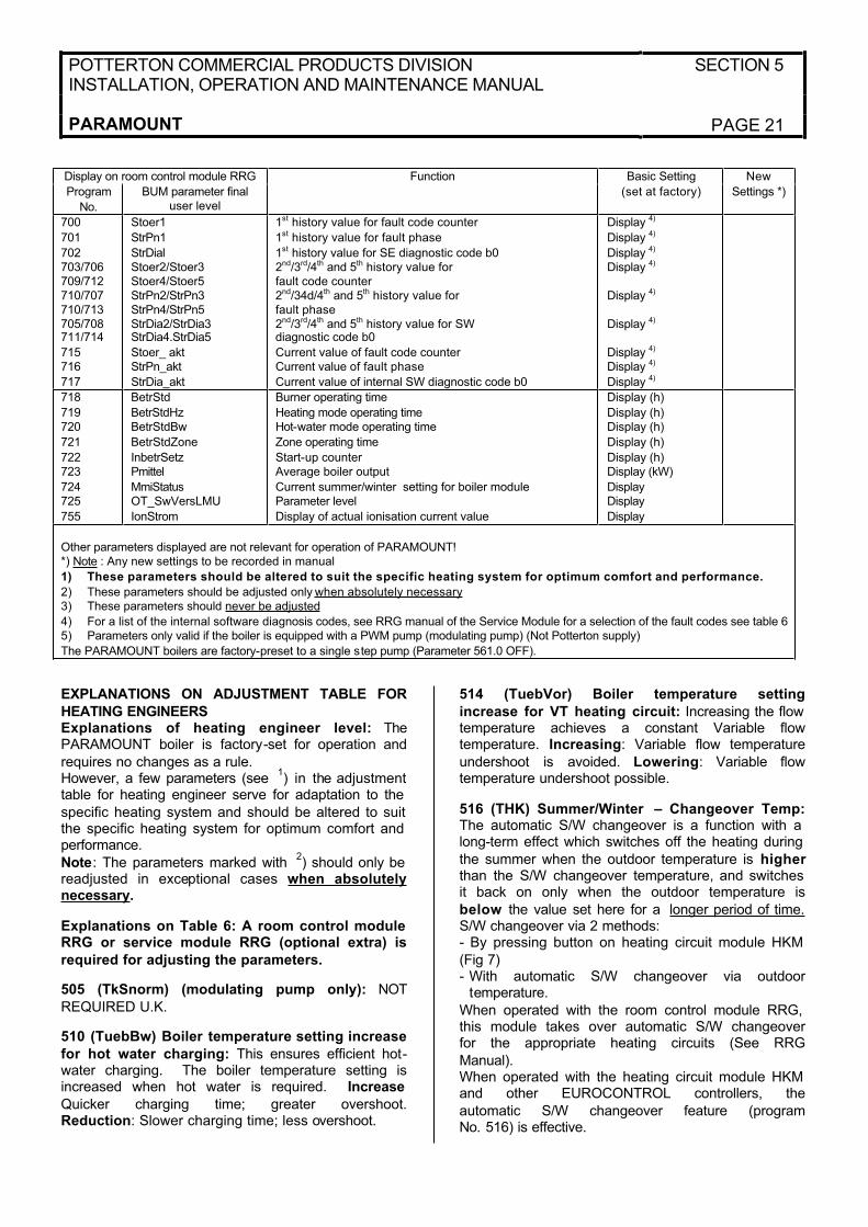
Other parameters displayed are not relevant for operation of PARAMOUNT!*) Note : Any new settings to be recorded in manual
1) These parameters should be altered to suit the specific heating system for optimum comfort and performance.
2) These parameters should be adjusted only when absolutely necessary3) These parameters should never be adjusted
4) For a list of the internal software diagnosis codes, see RRG manual of the Service Module for a selection of the fault codes see table 65) Parameters only valid if the boiler is equipped with a PWM pump (modulating pump) (Not Potterton supply)
The PARAMOUNT boilers are factory-preset to a single step pump (Parameter 561.0 OFF).
EXPLANATIONS ON ADJUSTMENT TABLE FOR
HEATING ENGINEERSExplanations of heating engineer level: ThePARAMOUNT boiler is factory-set for operation and
requires no changes as a rule. However, a few parameters (see
1) in the adjustment
table for heating engineer serve for adaptation to the
specific heating system and should be altered to suit the specific heating system for optimum comfort and performance.
Note: The parameters marked with 2) should only be
readjusted in exceptional cases when absolutelynecessary.
Explanations on Table 6: A room control module RRG or service module RRG (optional extra) is
required for adjusting the parameters.
505 (TkSnorm) (modulating pump only): NOT
REQUIRED U.K.
510 (TuebBw) Boiler temperature setting increase
for hot water charging: This ensures efficient hot-water charging. The boiler temperature setting isincreased when hot water is required. Increase
Quicker charging time; greater overshoot.Reduction: Slower charging time; less overshoot.
514 (TuebVor) Boiler temperature setting
increase for VT heating circuit: Increasing the flow temperature achieves a constant Variable flowtemperature. Increasing: Variable flow temperature
undershoot is avoided. Lowering: Variable flowtemperature undershoot possible.
516 (THK) Summer/Winter – Changeover Temp:The automatic S/W changeover is a function with a long-term effect which switches off the heating during
the summer when the outdoor temperature is higherthan the S/W changeover temperature, and switches it back on only when the outdoor temperature is
below the value set here for a longer period of time. S/W changeover via 2 methods: - By pressing button on heating circuit module HKM
(Fig 7)- With automatic S/W changeover via outdoor
temperature.
When operated with the room control module RRG, this module takes over automatic S/W changeoverfor the appropriate heating circuits (See RRG
Manual).When operated with the heating circuit module HKM and other EUROCONTROL controllers, the
automatic S/W changeover feature (programNo. 516) is effective.

SECTION 5 POTTERTON COMMERCIAL PRODUCTS DIVISIONINSTALLATION, OPERATION AND MAINTENANCE MANUAL
PAGE 22 PARAMOUNT
Turning off S/W changeover: The automatic S/Wchangeover feature operates with a switching
difference of + 1K. If a temperature of equal to or
greater than 30°C is set. in program No.516,changeover is not accomplished.
519 (TiAussen/Norm) (modulating pump only):NOT REQUIRED U.K.
ADJUSTING HEATING CURVE
520 (dTrAvsenk) Night Setback room temperature
setting: The room temperature setting is reduced by the value set here by a connected timer (e.g. EMS) in night setback mode. Adjustment range 0 to 10K the
room temperature setting made here is included incalculating the boiler temperature setting whenoutdoor compensation control is used.
521 (dTkTrNenn) (modulating pump only): NOTREQUIRED IN THE U.K.
532 (Sth1) bzw. 533 (Sth2) Heating curvesteepness HC1 or 2: When used without the room
control module RRG the steepness of the heatingcurves can be set here for the CTC (HC 1) or VTC (HC 2). Note: When used with a RRG, the heating
curves in the RRG are effective and can be set there!Standard value for heating curve (delivery state): The settings at the heating engineer level for the BMU
control centre can be made with the room controlmodule RRG. The parameters, which can be set are shown in
Table 5.The factory settings for the heating curve as follows:- CT heating circuit 25 and
- VT heating circuit 25 (See below)The heating curve can be adjusted as follows,depending on the system equipment.
- with room control module RRG: On heatingengineer level for RRG program No.70 or 80. The values from the RRG write over
parameters “532” and “533”!- with heating circuit module HKM: On boiler
module parameter “P 5” or with RRG as
service unit (Table 5)
534 (DtR1) and (DtR2) Correction of room
temperature setting HC1 and 2: These twoparameters shift the heating curve for heating circuit 1 and 2 parallel. If the room temperature setting is
not achieved with the heating curve set, this allows adaptation. (See table below)
536 (NHZmAX) Fan maximum speed for outputadjustment of Paramount: The maximum boiler output in the heating mode can be limited by reducing the speed of the fan to the desired output. For this purpose, set the maximum speed in program no. 536 (NhzMax) andprogram no.541 (PhzMax) according to Table 9.
Table 7: Max boiler output in heating mode (guide values)
Model Max heat load Para 536 rpm Para 541 %32 4900 7522 3300 44
Paramount 40
11 1700 1850 4900 7645 4400 69
Paramount 60
40 3900 6060 4750 8050 3950 67
Paramount 80
40 3150 53
537 (NqmodNenn) Speed stage at design point ofheating system: NOT REQUIRED IN THE U.K.
538 (NqmodMin) Min pump speed for heating system:NOT REQUIRED IN THE U.K.
541 (PhzMax) Degree of modulation in heating
mode: In order to ensure optimum operation of the PARAMOUNT, it is necessary to adapt the PWMsignal (% increments) for the max. degree of
modulation in the heating mode to the maximumspeed, program No. 536 (NhzMax) (see Table 7).
SETTINGS FOR THE BURNER
542 (PminHuKw) Min boiler input in kW: Differ
depending on type of boiler:
PARAMOUNT 40 →→ 9kW or
PARAMOUNT 60 →→ 14 kW or
PARAMOUNT 80 →→ 20 kW
543 (PmaxHuKw) Max boiler input in kW: Differ
depending on type of boiler:
PARAMOUNT 40 →→ 38 kW or
PARAMOUNT 60 →→ 58 kW or
PARAMOUNT 80 →→ 77 kW
Programs No. 542 and 543 serve only for indication
of the specific boiler output (no function) andbalancing the output when the cascade controllerEUROCONTROL BCA 2 is used.
POTTERTON COMMERCIAL PRODUCTS DIVISIONINSTALLATION, OPERATION AND MAINTENANCE MANUAL
SECTION 5
PARAMOUNT PAGE 23
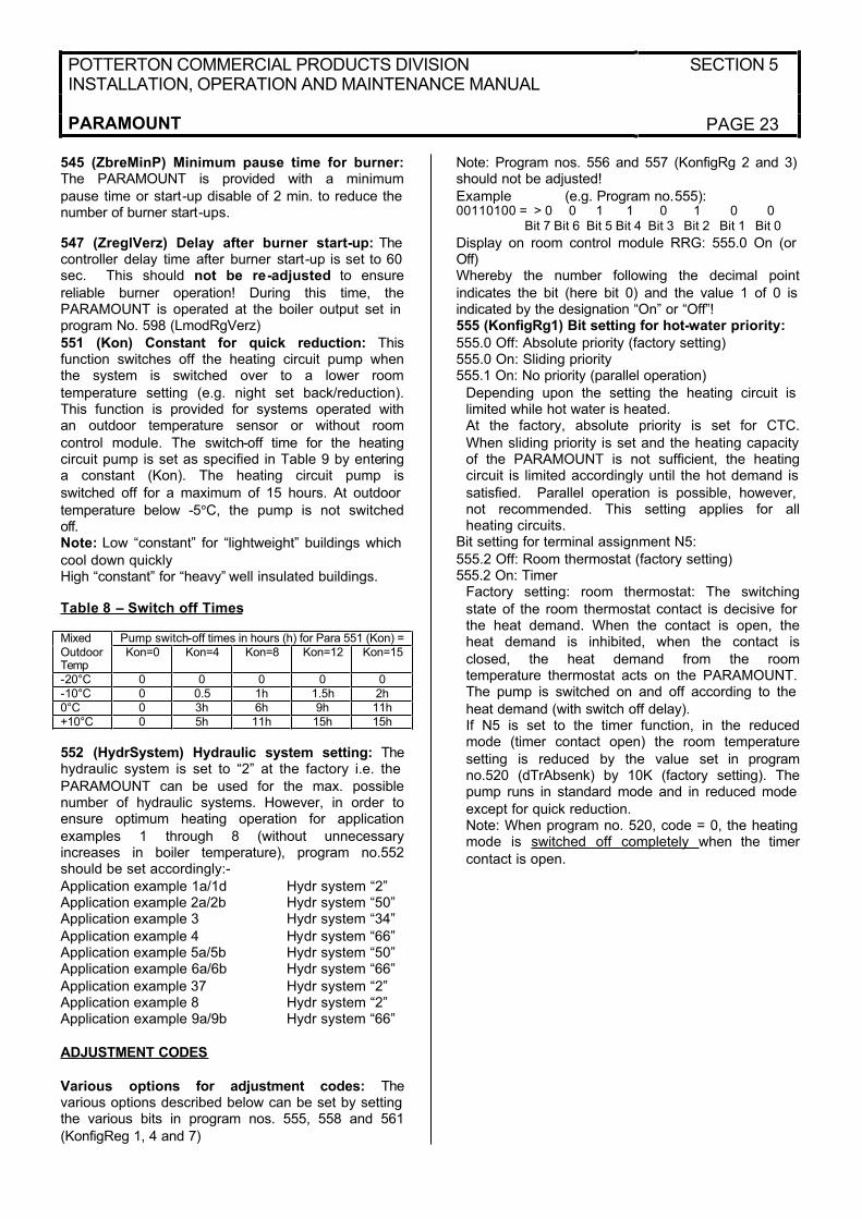
545 (ZbreMinP) Minimum pause time for burner:The PARAMOUNT is provided with a minimum
pause time or start-up disable of 2 min. to reduce the number of burner start-ups.
547 (ZreglVerz) Delay after burner start-up: The controller delay time after burner start-up is set to 60 sec. This should not be re-adjusted to ensure
reliable burner operation! During this time, thePARAMOUNT is operated at the boiler output set in program No. 598 (LmodRgVerz)
551 (Kon) Constant for quick reduction: Thisfunction switches off the heating circuit pump whenthe system is switched over to a lower room
temperature setting (e.g. night set back/reduction).This function is provided for systems operated withan outdoor temperature sensor or without room
control module. The switch-off time for the heatingcircuit pump is set as specified in Table 9 by enteringa constant (Kon). The heating circuit pump is
switched off for a maximum of 15 hours. At outdoor
temperature below -5°C, the pump is not switchedoff.Note: Low “constant” for “lightweight” buildings which
cool down quicklyHigh “constant” for “heavy” well insulated buildings.
Table 8 – Switch off Times
Pump switch-off times in hours (h) for Para 551 (Kon) =MixedOutdoorTemp
Kon=0 Kon=4 Kon=8 Kon=12 Kon=15
-20°C 0 0 0 0 0-10°C 0 0.5 1h 1.5h 2h0°C 0 3h 6h 9h 11h+10°C 0 5h 11h 15h 15h
552 (HydrSystem) Hydraulic system setting: Thehydraulic system is set to “2” at the factory i.e. the
PARAMOUNT can be used for the max. possiblenumber of hydraulic systems. However, in order toensure optimum heating operation for application
examples 1 through 8 (without unnecessaryincreases in boiler temperature), program no.552should be set accordingly:-
Application example 1a/1d Hydr system “2”Application example 2a/2b Hydr system “50”Application example 3 Hydr system “34”
Application example 4 Hydr system “66”Application example 5a/5b Hydr system “50”Application example 6a/6b Hydr system “66”
Application example 37 Hydr system “2”Application example 8 Hydr system “2”Application example 9a/9b Hydr system “66”
ADJUSTMENT CODES
Various options for adjustment codes: Thevarious options described below can be set by setting the various bits in program nos. 555, 558 and 561
(KonfigReg 1, 4 and 7)
Note: Program nos. 556 and 557 (KonfigRg 2 and 3) should not be adjusted!
Example (e.g. Program no.555):00110100 = > 0 0 1 1 0 1 0 0 Bit 7 Bit 6 Bit 5 Bit 4 Bit 3 Bit 2 Bit 1 Bit 0
Display on room control module RRG: 555.0 On (or Off)Whereby the number following the decimal point
indicates the bit (here bit 0) and the value 1 of 0 is indicated by the designation “On” or “Off”!555 (KonfigRg1) Bit setting for hot-water priority:
555.0 Off: Absolute priority (factory setting)555.0 On: Sliding priority555.1 On: No priority (parallel operation)
Depending upon the setting the heating circuit is limited while hot water is heated.At the factory, absolute priority is set for CTC.
When sliding priority is set and the heating capacity of the PARAMOUNT is not sufficient, the heatingcircuit is limited accordingly until the hot demand is
satisfied. Parallel operation is possible, however, not recommended. This setting applies for allheating circuits.
Bit setting for terminal assignment N5:
555.2 Off: Room thermostat (factory setting)555.2 On: Timer
Factory setting: room thermostat: The switching
state of the room thermostat contact is decisive for the heat demand. When the contact is open, theheat demand is inhibited, when the contact is
closed, the heat demand from the roomtemperature thermostat acts on the PARAMOUNT. The pump is switched on and off according to the
heat demand (with switch off delay).If N5 is set to the timer function, in the reducedmode (timer contact open) the room temperature
setting is reduced by the value set in programno.520 (dTrAbsenk) by 10K (factory setting). Thepump runs in standard mode and in reduced mode
except for quick reduction.Note: When program no. 520, code = 0, the heating mode is switched off completely when the timer
contact is open.
SECTION 5 POTTERTON COMMERCIAL PRODUCTS DIVISIONINSTALLATION, OPERATION AND MAINTENANCE MANUAL
PAGE 24 PARAMOUNT
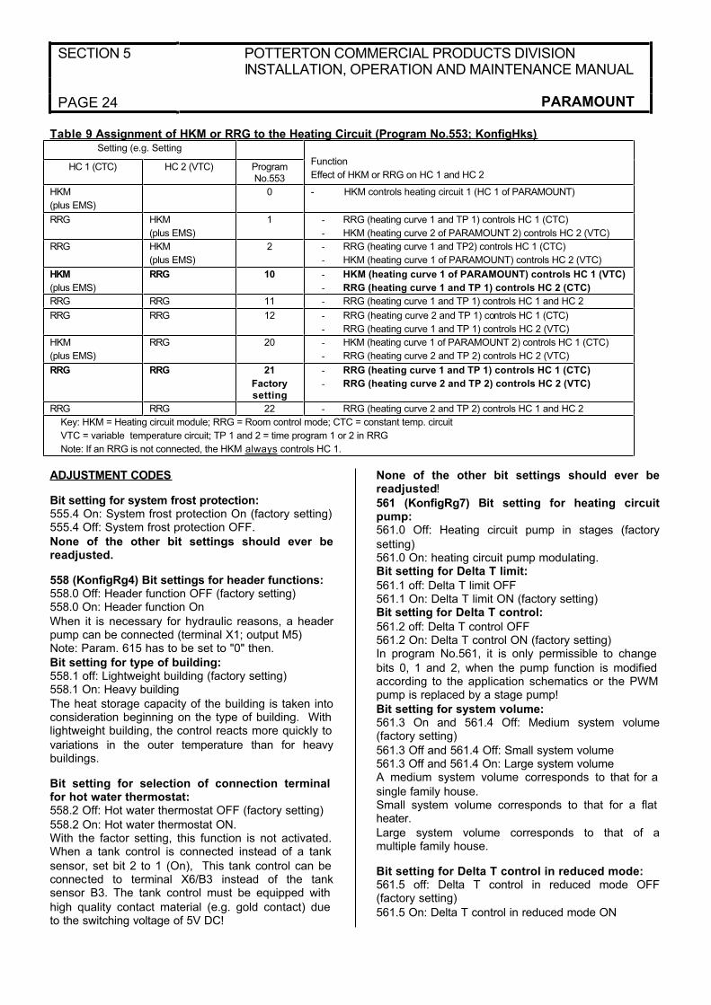
Table 9 Assignment of HKM or RRG to the Heating Circuit (Program No.553; KonfigHks)Setting (e.g. Setting
HC 1 (CTC) HC 2 (VTC) ProgramNo.553
Function
Effect of HKM or RRG on HC 1 and HC 2
HKM
(plus EMS)
0 - HKM controls heating circuit 1 (HC 1 of PARAMOUNT)
RRG HKM
(plus EMS)
1 - RRG (heating curve 1 and TP 1) controls HC 1 (CTC)
- HKM (heating curve 2 of PARAMOUNT 2) controls HC 2 (VTC)
RRG HKM
(plus EMS)
2 - RRG (heating curve 1 and TP2) controls HC 1 (CTC)
- HKM (heating curve 1 of PARAMOUNT) controls HC 2 (VTC)
HKM
(plus EMS)
RRG 10 - HKM (heating curve 1 of PARAMOUNT) controls HC 1 (VTC)
- RRG (heating curve 1 and TP 1) controls HC 2 (CTC)
RRG RRG 11 - RRG (heating curve 1 and TP 1) controls HC 1 and HC 2
RRG RRG 12 - RRG (heating curve 2 and TP 1) controls HC 1 (CTC)
- RRG (heating curve 1 and TP 1) controls HC 2 (VTC)
HKM
(plus EMS)
RRG 20 - HKM (heating curve 1 of PARAMOUNT 2) controls HC 1 (CTC)
- RRG (heating curve 2 and TP 2) controls HC 2 (VTC)
RRG RRG 21
Factory
setting
- RRG (heating curve 1 and TP 1) controls HC 1 (CTC)
- RRG (heating curve 2 and TP 2) controls HC 2 (VTC)
RRG RRG 22 - RRG (heating curve 2 and TP 2) controls HC 1 and HC 2
Key: HKM = Heating circuit module; RRG = Room control mode; CTC = constant temp. circuit
VTC = variable temperature circuit; TP 1 and 2 = time program 1 or 2 in RRG
Note: If an RRG is not connected, the HKM always controls HC 1.
ADJUSTMENT CODES
Bit setting for system frost protection: 555.4 On: System frost protection On (factory setting) 555.4 Off: System frost protection OFF.
None of the other bit settings should ever bereadjusted.
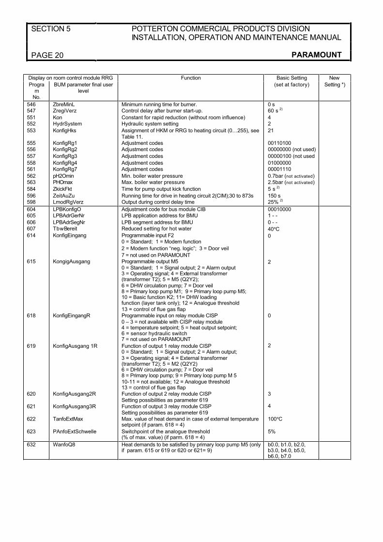
558 (KonfigRg4) Bit settings for header functions: 558.0 Off: Header function OFF (factory setting)558.0 On: Header function On
When it is necessary for hydraulic reasons, a headerpump can be connected (terminal X1; output M5)Note: Param. 615 has to be set to "0" then.
Bit setting for type of building:558.1 off: Lightweight building (factory setting)558.1 On: Heavy building
The heat storage capacity of the building is taken intoconsideration beginning on the type of building. With lightweight building, the control reacts more quickly to
variations in the outer temperature than for heavybuildings.
Bit setting for selection of connection terminal for hot water thermostat:558.2 Off: Hot water thermostat OFF (factory setting)
558.2 On: Hot water thermostat ON.With the factor setting, this function is not activated. When a tank control is connected instead of a tank
sensor, set bit 2 to 1 (On), This tank control can be connected to terminal X6/B3 instead of the tanksensor B3. The tank control must be equipped with
high quality contact material (e.g. gold contact) due to the switching voltage of 5V DC!
None of the other bit settings should ever bereadjusted!
561 (KonfigRg7) Bit setting for heating circuitpump:561.0 Off: Heating circuit pump in stages (factory
setting)561.0 On: heating circuit pump modulating.Bit setting for Delta T limit:
561.1 off: Delta T limit OFF561.1 On: Delta T limit ON (factory setting)Bit setting for Delta T control:
561.2 off: Delta T control OFF561.2 On: Delta T control ON (factory setting)In program No.561, it is only permissible to change
bits 0, 1 and 2, when the pump function is modified according to the application schematics or the PWM pump is replaced by a stage pump!
Bit setting for system volume:561.3 On and 561.4 Off: Medium system volume(factory setting)
561.3 Off and 561.4 Off: Small system volume561.3 Off and 561.4 On: Large system volumeA medium system volume corresponds to that for a
single family house.Small system volume corresponds to that for a flat heater.
Large system volume corresponds to that of amultiple family house.
Bit setting for Delta T control in reduced mode:561.5 off: Delta T control in reduced mode OFF(factory setting)
561.5 On: Delta T control in reduced mode ON
POTTERTON COMMERCIAL PRODUCTS DIVISIONINSTALLATION, OPERATION AND MAINTENANCE MANUAL
SECTION 5
PARAMOUNT PAGE 25
When bit 5 = 0, the pump is generally operated at the minimum pump speed setting program No. 538
(NqmodMin) in the reduced mode.When the heat requirement is too low in poorlyinsulated buildings, this function should be activated
(bit 5 = 1) so that the pump can operate in the same manner as in the standard mode!None of the other bit settings should ever by
readjusted.
598 (LmodRgVerz) Output during controller:In program No. 598 (LmodRgVerz) the burner output can be set at which the PARAMOUNT operates
during the delay time set in program No.547(Zreg1Verz) This output must never be changed!
SPECIAL FUNCTIONS604 (LPBKonfig0) 605 (LPBAdrGerNr) 606
(LPBAdrSegNr):Parameters 604, 605 and 606 are required only forthe PARAMOUNT in combination with zone
controllers, series EC ZR 1 / 2On the PARAMOUNT the following settings arealways required:
- LPB equipment address 605 (PBADRGerNr)Code = 1 and
- LPB segment address 606 (LPBAdrSegNr) =
Code 0Adjustment via bus module CIB: This setting can be made according to the instructions for the CIB bus
module.
Special function, modem function or door veilfunction 614 (KonfigEingang) Programmableinput F2 (low voltage):
Input F2 can be programmed for the special functions modem function (e.g. remote telephone switch) ordoor veil function. Only one function can be used for
input F2 in each case!A floating contact suitable for low voltage is required for actuation of input F2! To prevent contact
problems, we recommend installation of the HTS 2module in between (see HTS 2 instructions).Code 0 = Standard (factory setting) No effect
Code 1 = Mode function (e.g. remote controltelephone switch) The heating system can beswitched off or switched to the stand-by mode
centrally when a remote control telephone switch is connected. All protective functions (e.g. frostprotection, pump kicks etc.) remain active. The
heating requirements from external heating controls (e.g. ZR EC 1 / 2 or EC MSR) are also inhibited.Note: The modem function is active when the contact
is closed.Code 2 = Modem function “negative logic” See Code 1 for Function. Note: The modem function is active
when the contact is open!Code 3 = Door veil. In this setting the boilertemperature setting is set to the max. setting
(TkSmax) as well as a heat requirement for heating
circuit 1. This function is independent of summer and winter mode. Modulation of the burner output and hot
water priority remain unchanged. The door veilfunction can be activated with the HTS 2 (optional extra) on the PARAMOUNT heating circuit pump.
Relay closed: PARAMOUNT is heated up to max. boiler temperature. Relay open: PARAMOUNT isheld at temperature according to heating curve. See
HTS 2 instructions for connection.
Special function output M5 (programmableoutput) -Program No. 615 KonfigAusgang) (Code 0 to 12):
Only one function of output M5 can be used in each case!Code 0 = Standard (no function)
Code 1= Message output (e.g. for sub-terrain LPG systems).This output serves for control of an additional gas
valve for operation with LPG. When heat is required from the PARAMOUNT, the signal output is actuated by the BMU.
The signal output is not relevant for safety and istherefore not monitored. If a fault is present, thesignal output is switched off.
Code 2 = Alarm output (external fault signal): Factory setting on PARAMOUNT. If a fault is indicated,manual reset is required. The alarm output is set in
case of a fault.Code 3 = Operation message: The PARAMOUNTburner mode is displayed.
Code 4 = External transformer (transformer T2): Not availableCode 5 = Exit M5 (Q2Y2) Pump M2 (Q2) for 2
nd
pump circuit. See example 3, hydraulic system “34” or example 3b, hydraulic system “35”.Code 6 = Tank circulation pump M7 (Room control
with software > 1.4) Pump runs according to timerprogram of room control.Code 7 = Door veil function Pump M8 when door veil
function activated.Code 8 = Primary loop lump M6. Hydraulic system “2” (Parameter 552).
Code 9 = Primary loop lump M5 (see example 1b). Hydraulic system “2” or "50" (Parameter 552). Set param 632 to define which heat demand will make
the primary loop pump startCode 10, 11 = Function not available for ParamountCode 12 = Analogue threshold, M5 activated via
limits set by the entry of the relay modules CIR, CIST or CISP.

SECTION 5 POTTERTON COMMERCIAL PRODUCTS DIVISIONINSTALLATION, OPERATION AND MAINTENANCE MANUAL
PAGE 26 PARAMOUNT
Connect header pump for X1/M5:If hydraulic schematic requires a header pump
connect its plug to X1/M5. A heating circuit pump(CTC) is connected to exit M1.Programming header pump function:
-Program No. 615;Code 9 - 1. Set program No. 615 to Code 9-Program No. 632 (see below): Set bits b0 to b3
according to when the header pump has to startoperating.
618 (KonfigEingangR):
• 618 = 0 (factory setting): No function
• 618 = 4: Temperature setpointThe temperature setpoint is given by an externalanalogue signal (0-10V).
The maximum setpoint is set at parameter No.622.The setpoint can be between 5 and 100°C (limited by the max boiler temperature of 85°C). 5°C is theminimum threshold, i.e. the boiler is switched on at
6°C and switched off at 4°CThe heat demand is valid for HC 1. An additionalheat demand (e.g. from a VTC, is accepted, the
boiler temperature setpoint is then the maximum ofthe two heat demands).
• 618 = 5: Output setpoint
The analogue signal (0-10V) gives the outputsetpoint. This analogue signal is handed over to the boiler control BMU and is interpreted as a percentage
value on the specific output range of the boiler. The minimum threshold switching on and off the boilercan be set at parm. No. 623. The range between min.
and max. value is calculated into a power signal of 0-100%. If the analogue signal is higher than theminimal value, the boiler operates at min. output. At
the max. value, the boiler operates at max. output. If the analogue signal is below the minimum threshold, the output is not active. Other settings of Parameters
No. 618 are not possible with the CISP connected.If other clip in modules are connected, see thespecific installation manual for other setting
possibilities.
619 – 621 (KonfigAusgang1R to
KonfigAusgang3R):The CISP clip-in has 3 outputs that can beprogrammed.
The setting possibilities are the same as for param. No. 615, codes 0-12.Factory-presettings are:
619 (output 1) = 2 (alarm signal)620 (output 2) = 3 (operating signal)621 (output 3) = 4 (no function)
622 (TanfoExtMax) Temperature setpoint: The
heat demand is given by an analogue signal via input N11, see wiring diagram. Set this parameter to define the max. value of heat demand (Factory setting
100°C). Only applicable if param. No 618 = 4.
623 (PanfoExtSchwelle) Heat output setpoint: The
relative heat output is given by an analogue signal via input N11, see wiring diagram. Set thisparameter to define the minimum threshold from
which on the heat demand is accepted (in % of the max. value of the analogue signal. Only applicable if parameter No.618 =5).
632 (WanfoQ8) Heat demands to be satisfied by
primary loop pump (Only if param. 615 or 619 are set to "9"): To define which heat demand will make pump M5 start. The activation is independent from
the hydraulic system and can be used for bothcentral heating and DHW generation.
b0.1: M5 ON for zone control ZR EC 1 / 2 b1.1: M5 ON for heating circuit 2 (VTC)b2.1: M5 ON for heating circuit 1 (CTC)
b3.1: M5 ON for DHW generationNote: These bits can be set in any combination
724 (MmiStatus) Current summer/winter settingfor boiler module: The current summer/wintersetting for the boiler module is displayed:
724.0 0 or 1: Current summer/winter setting (Value 0 = Summer, Value 1 = Winter)724.1 0 or 1: Current summer/winter switchover
(Value 0 = Manual, Value 1 = Automatic)
755 (IonStrom) Ionisation current actual value
display: The current ionisation current is indicatedwhen the burner is in operation.
Hot-water control: The hot water requirement has priority over heat demand from a heating circuit.
Automatic day heat limit: The automatic day heat limit is effective only when the outdoor temperaturesensor is connected.
This is a rapid-acting economy function, whichswitches off the boiler when the mixed outdoortemperature is higher than the room temperature
setting (standard or reduced)The boiler switches back on when the mixed outdoor temperature is 2K below the room temperature
setting.For outdoor temperature control with no roominfluence, the actual room temperature is taken into
consideration.The automatic day heating limit is active, “ECO”appears on the display of the room control module
RRG.
POTTERTON COMMERCIAL PRODUCTS DIVISIONINSTALLATION, OPERATION AND MAINTENANCE MANUAL
SECTION 5
PARAMOUNT PAGE 27
Quick heat-up: Only possible when room controlmodule RRG is connected and room sensor active.
Quick heat-up/quick reduction is effective only when the heating circuit is switched over from frostprotection or reduced mode to standard operation
and the room temperature is simultaneously more
than 1.5°C below the room temperature setting (even when room temperature setting is increased on room
control module).
Quick heat-up is terminated when the room
temperature is less than 0.25°C below the roomtemperature setting,
Rapid reduction (with room sensor): When theheating circuit is switched over from Standard mode to Reduced mode or Frost protection mode, the rapid
reduction feature is active (heating circuit pump isswitched off).
Boiler frost protection: On systems with outdoortemperature sensor, the system frost protectionfeature is switched on and off by the outdoor
temperature. In this case the heating circuit pump is switched as follows:
Outdoor Temperature Pumps
<4°C
-5°C to 1.5 C
>1.5°C
Continuous operation pumps ON
Pumps on for 10 min. every 6 hours
Pumps OFF
Building Frost Protection: The building is protected against frost in all operating modes:
- Room control module RRG (with effective roomsensor): The frost protection room temperature
setpoint is effective in all modes.
- Heating circuit module HKM with timer EMS or
room control module RRG (without effective roomsensor): The building frost protection is ensured by the heat requirement in the Standard and reduced
mode.
- Room thermostat RAV/RTW/RTD: Building
frost protection is ensured by the heat requirementfrom the room thermostat.
Hot Water Frost Protection: The tank is protected against freezing because the tank is automaticallycharged when the temperature drops below the
setting.
Restart Inhibit (burner starts): To reduce the
number of burner start-ups, the boiler is equippedwith a start-up inhibit of 3 min.
Anti-Legionnaires disease function (only withroom control module RRG): Heat-up is started
once a week on Monday with the first hot-watercharge and lasts for a maximum of 2.5 hours. In the “Stand-by” mode, the function is inhibited. If it is
inhibited for longer than 1 day, the anti legionnaires disease function is repeated as soon as the hot water is enabled.
Chimney Sweep Function: The so-called “Chimney
Sweep” function can be activated by pressing theChimney Sweep button (12) (>3 sec) (fault display (8) flashes once). The burner is switched on and heats
up the PARAMOUNT at the maximum boiler output
until the temperature monitor trips at 82°C.Note: “SF” appears on display (13) and the fault
indicator (8) flashes!
Deactivation of Chimney Sweep function: Press the Chimney Sweep button (12) (min 1 sec) to
deactivate the chimney sweep function.
Emergency Operation Functions: In the event ofcomponent failure, an error message is output (see
Table 11) leading to start-up prevention andemergency operation function, however not to faultswitch-off.
Moreover, emergency operation is accomplished inthe event of the following faults:
• Hot water mode:
Defective tank sensor: The hot water mode isinhibited, heating operation for the heating circuit is still ensured.
Defective room control module RRG or heating circuit module HKM: The hot water temperature is regulated to the value set on the boiler module under
parameter “P2”.
• Heating mode:
Defective outdoor temperature sensor: In the event of a defective outdoor temperature sensor, thesystem is regulated to a boiler temperature
corresponding to an outdoor temperature of 0°C.
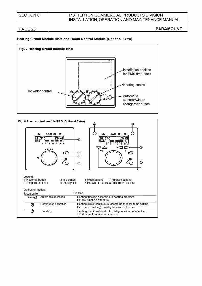
SECTION 6 POTTERTON COMMERCIAL PRODUCTS DIVISIONINSTALLATION, OPERATION AND MAINTENANCE MANUAL
PAGE 28 PARAMOUNT
Heating Circuit Module HKM and Room Control Module (Optional Extra)
Fig. 7 Heating circuit module HKM
Automaticsummer/winter
changeover button
Heating control
Installation position
for EMS time clock
Hot water control
Fig. 8 Room control module RRG (Optional Extra)
Legend:1 Presence button 3 Info button 5 Mode buttons 7 Program buttons2 Temperature knob 4 Display field 6 Hot water button 8 Adjustment buttons
Operating modes:
Mode button Function
Automatic operation Heating function according to heating programHoliday function effective
Continuous operation Heating circuit continuous (according to room temp settingOr reduced setting); holiday function not active
Stand-by Heating circuit switched off Holiday function not effective;Frost protection functions active

POTTERTON COMMERCIAL PRODUCTS DIVISIONINSTALLATION, OPERATION AND MAINTENANCE MANUAL
SECTION 6
PARAMOUNT PAGE 29
Heating Circuit Module HKM (Fig.7) Suppliedwith the PARAMOUNT
Operation without Outdoor Temperature Sensor:- Boiler temperature setting on heating circuit
control- Hot water temperature setting on hot-water
control
Operation with Outdoor Temperature Sensor: - Room temperature setting on heating circuit
control- Hot water temperature setting on hot water
control.
Automatic Summer/Winter Switchover: With the automatic Summer/Winter switchoverbutton it is possible to switch back and forth
manually between Summer and Winter andAutomatic mode.
LED “Auto” LED “Auto” LED “Auto”
O O •LED LED LED
O • o OR • *)
*) For example the display for winter mode is active
(• = active) depending on the automatic setting.
Room Control Module RRG (Fig 8)With the room control module (optional extra) you
can- control the functions from the room (remote
control)
- make settings (e.g. your own timer programs)- call up information (e.g. temperature values)
etc.
All possibilities are described in the instructionsincluded with the room control module. Only a few of the most important functions are described
below.
Presence Button
With the Presence button you can manuallymanipulate the set timer program (heatingprogram):
- “Sun” symbol: Heating operates at settemperature.
- “Moon” symbol: Heating operates at reduced
temperatureThe Presence button is effective until the timerprogram switches the next time.
The Presence button has no effect on the hot water heating!
Temperature KnobYou can readjust the set temperature with thetemperature knob. One increment corresponds to
approx. 1°C. Before changing the temperature
setting on the temperature knob, set thethermostatic valves to the desired temperature.
Correct again only after the temperature hasadapted.
Temperature Sensor in Room Control Module
The temperature sensor integrated into the room
control module is effective only when the roominfluence is enabled on the PARAMOUNT.
Error Messages
No display: - Faulty connection from room control module to PARAMOUNT
- PARAMOUNT switched off or no mains- Room control module defective- Room control module and PARAMOUNT not
compatibleDisplay OFF - PARAMOUNT not set to “Automatic mode”
Display ---: No sensor present or sensor defective.
SERVICE
Cleaning: The heat exchanger and burner should be cleaned by a certified gas installer. Before
starting the work, shut off the gas shut-off device and the hot water shut-off valves and disconnect all power to the boiler.
Condensate Trap: The condensate trap should be cleaned every one to two years. For this purpose,
loosen the threaded fitting on the trap and pull the trap off downward. Completely remove the traptogether with hose from boiler, disassemble and
rinse with clear water. Reinstall the trap in theopposite order.
Replacing Air Vent: Ensure that the air vent is replaced only with genuine replacement part when defective to ensure optimum venting!
Removing Gas Burner: Burner: Before cleaningthe heat exchanger, remove the gas burner. For
this purpose, disconnect the electric connections to the fan at the plug connector, pull the air hose off the fan and disconnect the plug from the
electrodes.
• Remove silencer
• Disconnect threaded fittings for gas connection pipe on mixing duct and on gas valve. Remove
gas connection pipe and gas injector. Loosenthe 5 mounting nuts on the mixing duct/heat exchanger. Pull burner out toward front
together with mixing duct and fan.
• Clean burner pipe with soft brush.When installing, use new gaskets, particularly for
the gas connection pipe.
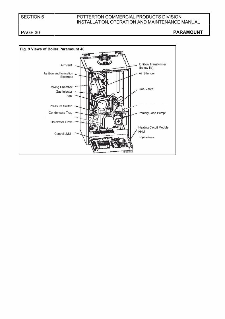
SECTION 6 POTTERTON COMMERCIAL PRODUCTS DIVISIONINSTALLATION, OPERATION AND MAINTENANCE MANUAL
PAGE 30 PARAMOUNT
Air Vent Ignition Transformer (below lid)
Ignition and Ionisation Electrode
Air Silencer
Gas Valve
Primary Loop Pump*
Mixing Chamber
Gas Injector
Fan
Pressure Switch
Hot-water Flow
Control LMU
Condensate Trap
Heating Circuit Module
HKM
Fig. 9 Views of Boiler Paramount 40
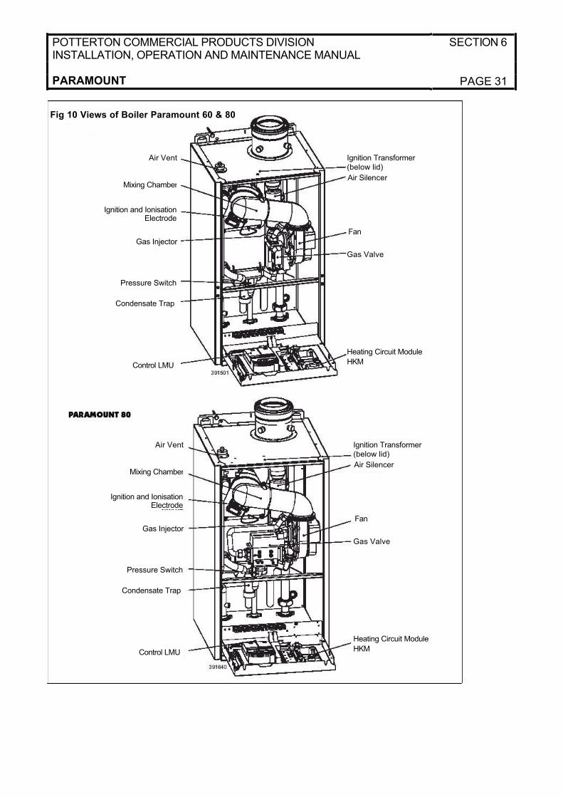
POTTERTON COMMERCIAL PRODUCTS DIVISIONINSTALLATION, OPERATION AND MAINTENANCE MANUAL
SECTION 6
PARAMOUNT PAGE 31
Air Vent Ignition Transformer (below lid)
Ignition and Ionisation Electrode
Air Silencer
Gas Valve
Mixing Chamber
Fan
Pressure Switch
Gas Injector
Control LMU
Condensate Trap
Heating Circuit Module
HKM
Fig 10 Views of Boiler Paramount 60 & 80
Air Vent Ignition Transformer (below lid)
Ignition and Ionisation Electrode
Air Silencer
Gas Valve
Mixing Chamber
Fan
Pressure Switch
Gas Injector
Control LMU
Condensate Trap
Heating Circuit Module
HKM
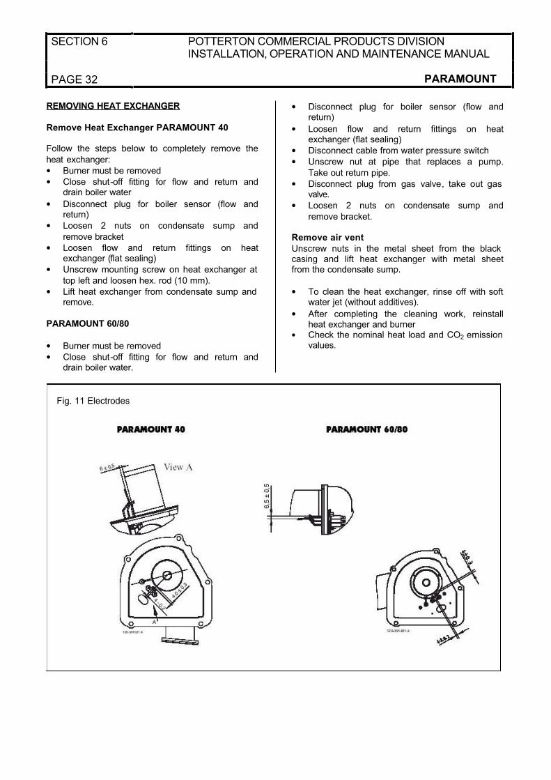
SECTION 6 POTTERTON COMMERCIAL PRODUCTS DIVISIONINSTALLATION, OPERATION AND MAINTENANCE MANUAL
PAGE 32 PARAMOUNT
REMOVING HEAT EXCHANGER
Remove Heat Exchanger PARAMOUNT 40
Follow the steps below to completely remove the
heat exchanger:
• Burner must be removed
• Close shut-off fitting for flow and return anddrain boiler water
• Disconnect plug for boiler sensor (flow andreturn)
• Loosen 2 nuts on condensate sump and
remove bracket
• Loosen flow and return fittings on heatexchanger (flat sealing)
• Unscrew mounting screw on heat exchanger at
top left and loosen hex. rod (10 mm).
• Lift heat exchanger from condensate sump and remove.
PARAMOUNT 60/80
• Burner must be removed
• Close shut-off fitting for flow and return anddrain boiler water.
• Disconnect plug for boiler sensor (flow andreturn)
• Loosen flow and return fittings on heatexchanger (flat sealing)
• Disconnect cable from water pressure switch
• Unscrew nut at pipe that replaces a pump.
Take out return pipe.
• Disconnect plug from gas valve, take out gas valve.
• Loosen 2 nuts on condensate sump and
remove bracket.
Remove air vent
Unscrew nuts in the metal sheet from the black casing and lift heat exchanger with metal sheetfrom the condensate sump.
• To clean the heat exchanger, rinse off with soft water jet (without additives).
• After completing the cleaning work, reinstallheat exchanger and burner
• Check the nominal heat load and CO2 emission values.
Fig. 11 Electrodes

POTTERTON COMMERCIAL PRODUCTS DIVISIONINSTALLATION, OPERATION AND MAINTENANCE MANUAL
SECTION 6
PARAMOUNT PAGE 33
CONTROL CENTRE
Electrodes: To ensure proper function of theignition and ionisation, ensure that installationlength and spacings are observed as shown in
Fig.11.The ionisation current should have the followingvalues for burner operation:
- at min. output > 5 µ A, DC (switching threshold at 0.7 µA, DC)
- at max. output > µA, DC
Ionisation Current Indicator: The current ionisationcurrent can be checked as follows directly in µA:
- on boiler module (1) under parameter “C 1”- using room control module RRG (optional extra)
Function Description: Control and monitoring ofburner by BMU control centre with ionisationelectrode.
• Automatic start-up according to program withmonitoring of flame formation
The operation itself can be varied using parameters
• The display on the control panel indicates the
individual operating or program states withnumbers or letters (see Table 10)
Reset: Following Reset (power OFF/ON) the BMU control centre starts in the Home mode.
Fault Switch Off: Safety switch-off in the event of flame failure during operation. After each safety
switch-off, a new ignition attempt is accomplished according to program. If this does not lead to flame formation, a fault shut-off is accomplished. In the
event of a fault shut-off, press the Reset button on the control panel.In the event of fault (red light) the numbers on the
display on the control panel indicates the cause of the fault (see Table 11).
Burner Does Not Operate: No power to controlcentre, e.g. no “Burner ON” signal from heatingcircuit control (see Table 11).
Burner Goes to Fault: Without flame formation: No ignition, ionisation electrode has short circuit to
ground, no gas. In spite of flame formation, burner goes to fault after expiration of safety time:Ionisation electrode defective or dirty. Ionisation
electrode not submerged in flame, boiler connected with reverse polarity.
Table 10 Operating Phases of Control CentreCode “A 4” Operating State Function Description
0 Standby (no heat requirement) Burner on standby
1 Start disable
2 Fan start-up Self-test for burner start and fan start-up
3 Pre-purging time Pre-purging fan deceleration time to starting load speed
4 Waiting time
5 Ignition phase Ignition and start of safety time
Flame formation, ionisation current build up
6 Safety time constant
7 Safety time variable
10 Heating operation Room heating mode, burner in operation
11 Hot water mode Hot-water tank charging, burner in operation
12 Parallel operation for heating and hot water
20 Subsequent ventilation with last operating fan speed Fan continues to run
21 Subsequent ventilation with pre-purging fan speed Fan continues to run
22 Shut down Self-test after controlled shut-down
99 Fault position The current fault code is indicated, see Table 13
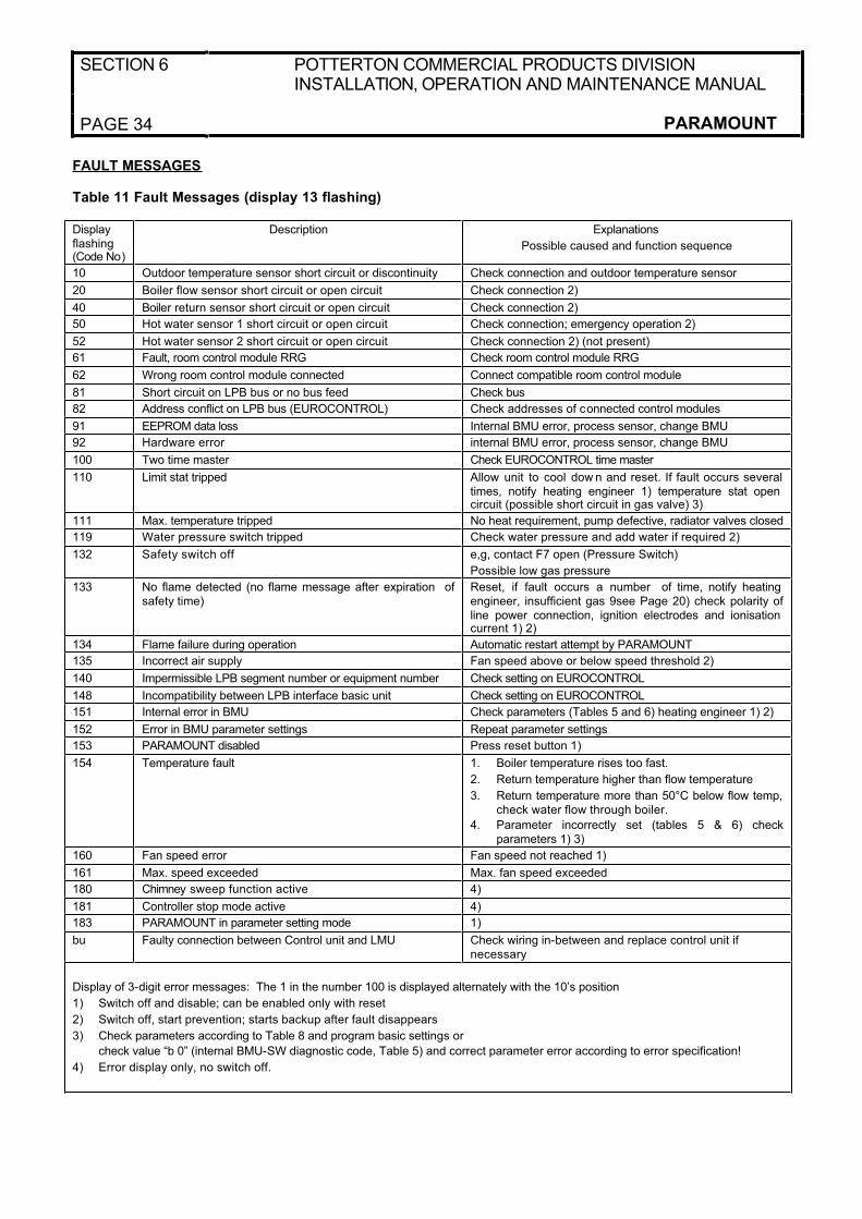
SECTION 6 POTTERTON COMMERCIAL PRODUCTS DIVISIONINSTALLATION, OPERATION AND MAINTENANCE MANUAL
PAGE 34 PARAMOUNT
FAULT MESSAGES
Table 11 Fault Messages (display 13 flashing)
Displayflashing(Code No)
Description Explanations
Possible caused and function sequence
10 Outdoor temperature sensor short circuit or discontinuity Check connection and outdoor temperature sensor
20 Boiler flow sensor short circuit or open circuit Check connection 2)
40 Boiler return sensor short circuit or open circuit Check connection 2)
50 Hot water sensor 1 short circuit or open circuit Check connection; emergency operation 2)
52 Hot water sensor 2 short circuit or open circuit Check connection 2) (not present)
61 Fault, room control module RRG Check room control module RRG
62 Wrong room control module connected Connect compatible room control module
81 Short circuit on LPB bus or no bus feed Check bus
82 Address conflict on LPB bus (EUROCONTROL) Check addresses of connected control modules
91 EEPROM data loss Internal BMU error, process sensor, change BMU
92 Hardware error internal BMU error, process sensor, change BMU
100 Two time master Check EUROCONTROL time master
110 Limit stat tripped Allow unit to cool dow n and reset. If fault occurs several times, notify heating engineer 1) temperature stat open circuit (possible short circuit in gas valve) 3)
111 Max. temperature tripped No heat requirement, pump defective, radiator valves closed
119 Water pressure switch tripped Check water pressure and add water if required 2)
132 Safety switch off e,g, contact F7 open (Pressure Switch)
Possible low gas pressure
133 No flame detected (no flame message after expiration of safety time)
Reset, if fault occurs a number of time, notify heating engineer, insufficient gas 9see Page 20) check polarity of line power connection, ignition electrodes and ionisation current 1) 2)
134 Flame failure during operation Automatic restart attempt by PARAMOUNT
135 Incorrect air supply Fan speed above or below speed threshold 2)
140 Impermissible LPB segment number or equipment number Check setting on EUROCONTROL
148 Incompatibility between LPB interface basic unit Check setting on EUROCONTROL
151 Internal error in BMU Check parameters (Tables 5 and 6) heating engineer 1) 2)
152 Error in BMU parameter settings Repeat parameter settings
153 PARAMOUNT disabled Press reset button 1)
154 Temperature fault 1. Boiler temperature rises too fast.
2. Return temperature higher than flow temperature
3. Return temperature more than 50°C below flow temp, check water flow through boiler.
4. Parameter incorrectly set (tables 5 & 6) checkparameters 1) 3)
160 Fan speed error Fan speed not reached 1)
161 Max. speed exceeded Max. fan speed exceeded
180 Chimney sweep function active 4)
181 Controller stop mode active 4)
183 PARAMOUNT in parameter setting mode 1)
bu Faulty connection between Control unit and LMU Check wiring in-between and replace control unit if necessary
Display of 3-digit error messages: The 1 in the number 100 is displayed alternately with the 10’s position
1) Switch off and disable; can be enabled only with reset
2) Switch off, start prevention; starts backup after fault disappears
3) Check parameters according to Table 8 and program basic settings or
check value “b 0” (internal BMU-SW diagnostic code, Table 5) and correct parameter error according to error specification!
4) Error display only, no switch off.
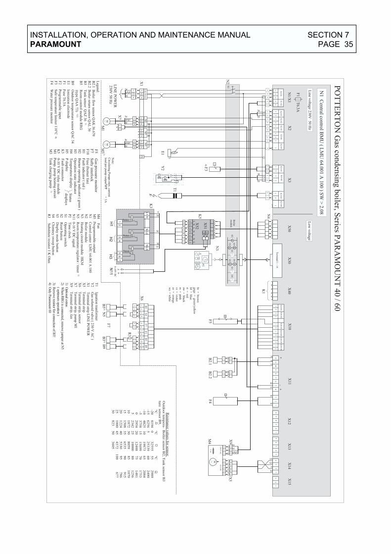
��
��
��
��
���
���
��
� �
���
�������������
��
��
��
��
���
�����
�
��
��
����� !�� ���"!�
#���$%� ��
��
����� ��!������&�'��()&
���!��*�
�����+�� !�&)&
�� ��!�� ��
,�����&
�'�����!���-����� ��!�� ��-�.,/
����� �0��
�&�) !���
1#
2��
�#
1#
2�#
�#
1#
2�,
�#
1#
2��
�#
,
1#
2�*�
��
�1�
1#
1*
�1
,�
1�
�1
��
1�
�1
�#
1�
,1
��
1�
*
�#
,�
#
1�
2��
1�
2�#
��
���&
� ���
�2���
3�
�#
,�
*�
45
6�
��
��
#,
�*
��
#,
�*
�#
,�
�#
,
�
��
3��
�
#,
��7
8�9
#�
�78:
9
�#
,
�#
,
16
1*
,,
##
��
**
��
��
;�
��'�
�!���#
,�
7��*
��<
=;
�>
�'�
�!��
�#
3�
�#�
#
.#
8�
�#
�#
.#
8#
�#
� �
� �
� !
�
' �
� �
� !
� �
� �
??
2
�#
,�
#�
#,
��
#
.�
����
&�
�)
��
<�
<#
<*
<�
�,
�#
<,
�#
�,
��
.*
#�
�*
.,
,�
.6
�#
,�
*�
45
6�
��
��
#
�#
1�
�#
�#
�#
�#
34
.*
�*
34
.,
.6
�,
3#
1�
�2�
�1
��
2�*
1�
�2�
�
�#
�#
�#
�#
�#
�#
1�
�2�
�1
��
2�#
1�
�2�
,
>
>
� !
� �
1,
2��
1,
2�#
1,
2�,
1,
2��
�#
�#
�#
�
1,
� �
� �
��
@#
�#
,
�#
�#
�#
�
��
1�
�1
4
;�
������
;A�
���
�$
��
�#,
�7
�*�
�<=
#
��
;;
�
�;
�,
;�
;�
;�
��
;�
����
>��
��
�*
�,
�#
<�
�����3)
�!�� �
��!���+����
��
<#
�����.)
� ����
��!�
���
���!�
��+�����
��
<,
������
��!��
�!!��� �
��!��
<�
�������&
��!)
�����
�0
<*
��������
� �0
B,
�3
)�!���
��!��
B*
������2�
��7
�:9
����0�&
��
)���
�
����
���
!!)
��
�0
;��
� �
C������������������������������������
.#
8���.
������-��
>��
���D
�B
�,�
8�4
�
.#
8#��.
��������!)
� ��
���D
�;
�,�
.,
������
E��
����D
�F
�,�
�� ��
.*
�������
�&
���
!����&
��
)����
��
����������+!0
��D�
��4
,��� �
�#�
.6
������)
!��
���!�&
��!)
���� �
��D�
9�,
�
��
�����A�
�=!��
�����!���
�
3�
�����3)
����
8,�
3#
��������
��&
&�
����
)!
3,
������-��!�&
��!)
�����&�!����
��
G9���
3�
�����$!���
��)���&
�
�!��
��
�����)
&
�� )
&
�%�!�
������)
�!���
�,
�����
E��%
���
��
)&
��� �
����
��
�A�
!��
�!�
-��&
��
@#
��
����
���
�'�'
��+�#,
��7
��9
��
1�
��
��&�
��!�� �;
A��
���
$�
�
1*
��������&
� ��!��
1�
��������&
� ��!��
��� �
��
14
��������&
� ��!��
�� )
&
���
16
��������&
� ��!��
��-
����
�3
�*
������
��&
&�
����)
! )
!
��
����9�
!��
���� !����;
��
���
8��
���
���
�
�#
����.�
�����&�
�)
��
�,
����<�!�
������)
�!�&�
�)
����<B
���
�*
������
�&
�!�&
��!)������
)�!�
����!�&���� �
�
��
����
2��
�7�:
9���
�
�#
�������&
������E
�
��
������
��!� �
�>�!�%
�#
��������!��
)!!�
�,
�����:�
�0�&
��
���)
!!�
��
�����9%
�&
�0�>
�� ��
)!!�
�,
��
)�
!�!)!�����!�
����B
��%
&
����������������� ���!
���'
�)
��-�
���
���
���)
!��
���!�
&
��
2��.�
������
�
��.#
���
E��
�
��.,
��!)��
���
���.
6����
��
��G9
��
G9�
�����G9
��������������
�2#
��
5�
6�
��
�,
#*
**
�����**
���������#
65
6�
�2�
*�
�#
*�
�*
�#
*,
,6
�������
���������#
�6
��
�2�
��
�5
#*
��
��
�6
54
,������
*�����������#
�5
��
���2*
�,
4*
5�
�*
��
*�
66
�����4�
������������4
*,
�
�����
�#
6*
��
#�
��
#�
55
�����4*
����������
�5
��
����*
�#
,�
#�
#*
��
��
��
�����5�
������������#
*�
�
��
��
�5
4#
�,
��
5�
*6
�����5
*�
����������
4�
�
��
*�
�*
�5
�,
*�
�*
,*
�����6
��������������6
�*
�
�#
��
�#
#�
��
��
*,
,�
�����6
*�
����������45
��
�#
*�
��
��
��
*�
�,
4#
����
��
��������������4
4�
�,
��
5#
,�
*�
�,
��
*
� �� � �
� �
� � �
� �
� �
� � �
� �
� �
��
!�C
9���)
�!� �
��)
&
�&"
8��)���
!�
���
� ���
)&
��
)!
)!��
�A����������H��
��
�&"
��
8,�
��
B�
3�
��
3)
��+�)
� ���-
�
� �
� �
� � �
34
��
-!0��
!�����E
�
����I
�����
>
�
����I
������
�0����
>
����I
����)
�
�!��I�����
>��I
�����E
���I��
� E
'���I
��'��
��!
����I
����
��
>��I
�>%
�!���
3,
�
3*
3*
��
� ��)
���&�
�!�
��
B*
�#
�#
�#
,
;�
;�
�;
;
�#
B,
��
��
��
��
�
��
��
��
� � � � � �
� � � � � �
� � � � � �
� !
� �
� �
>
�#
��
��
1*
�
1*
#
�#
�#
,�
#
�2�
�7
�:9
��
�
��
��9�
!�����
!����.
��
�+�;�
���
�8�
��
����
��
����$
�J�#
8�5
��
� �
INSTALLATION, OPERATION AND MAINTENANCE MANUAL SECTION 7
PARAMOUNT PAGE 35
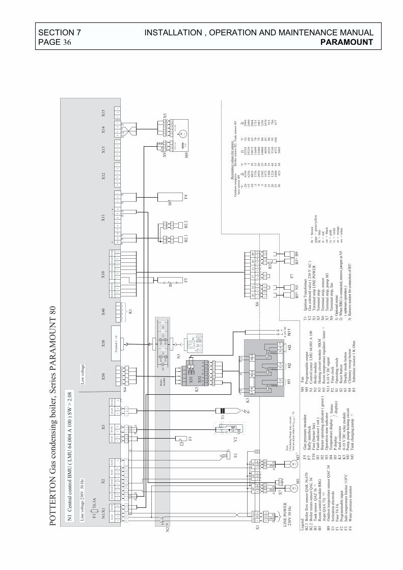
��
��
��
��
���
��
�
��
�
���
���
����
���
���
��
��
��
��
��5
��
1#
2��
�#
1#
2�#
�#
1#
2�,
�#
1#
2��
�#
,
1#
2�* �
��
�1�
1#
1*
�1
,�
1�
�1
��
1�
�1
�#
1�
,1
��
1�
*
�#
,�
#
1�
2��
1�
2�#
��
���
&�
���
�2��
�
3�
�#
,�
*�
45
6�
��
��
#,
�*
��
#,
�*
�#
,�
�#
,
�
��
3��
�
#,
��7
8�9
#�
�78:
9
�#
,
�#
,
16
1*
, ,
# #
� �
* *
� �
��
;�
��'
��!
���
#,
�7
��*
��<
=;
�>
�'�
�!�
�
��
��9
� !�
���
�
!��
��.
��
�+�;
��
���
8��
���
���
���
��$
�J�#
8�5
�#
3�
�# �
#
.#
8�
�#
�#
.#
8#
�#
��
��
�!
�
'�
��
�!
��
��
??
2
�#
,�
#�
#,
��
#
.�
����
&�
�)
��
<�
<#
<*
<�
�,
�#
<,
�#
�,
��
.*
#�
�*
.,
,�
.6
�#
,�
*�
45
6�
��
��
#
�#
1�
�#
�#
�#
�#
34
.*
�*
34
.,
.6
�,
3#
1�
�2�
�1
��
2�*
1�
�2�
�
�#
�#
�#
�#
�#
�#
1�
�2�
�1
��
2�#
1�
�2�
,
>
>
�!
��
1,
2��
1,
2�#
1,
2�,
1,
2��
�#
�#
�#
�
1,
��
��
��
@#
�#
,
�#
�#
�#
�
��
1�
�1
4
;�
����
��
;A�
���
�$
��
�#,
�7
�*�
�<=
#
��
;;
�
�;
�,
;�
;�
;�
��
;�
���
�>
���
��
*�
,
�#
<�
����
�3)
�!��
�
��!
���
+���
���
<#
����
�.)
� ��
��
��!
� �
��
���
!�
��+�
���
� ��
<,
����
��
��!
��
�!
!���
�
��!
��
<�
����
���&
��
!)
����
�
�0
<*
����
����
�
�0
B,
�3
)�!
���
��!�
�
B*
����
��2�
��7
�:9
����
0�&
��
)��
��
����
���
!!)
��
�
0
;��
� �
C���
����
����
����
����
����
����
����
����
�
.#
8���
.�
����
�-��
>�
� �
��D
�B
�,�
8�4
�
.#
8#��
.�
����
���!
)�
��
���
D�
;�,
�
.,
����
��
E�
� �
���D
�F
�,�
���
�
.*
����
���
�&
���
!�
���
&�
�)
����
��
����
����
��+!
0
��D
��
�4,
����
�#�
.6
����
��)
!��
���
!�&
��
!)
���
� �
��D
�9
�,�
��
����
�A�
�=
!��
��
���!
���
�
3�
����
�3)
���
�8,
�
3#
����
����
��
&&
���
��
)
!
3,
����
��-
��!�
&
��!
)��
���&
�!��
���
�G9
���
3�
����
�$!
���
��
)��
�&�
�!
��
��
����
�)
&
��
)&
�%
�!�
�
����
�)�!
���
�,
����
�
E��
%�
��
��
)&
��
��� ��
�
����
� !
��
���"
!�
#���
$%�
��
��
���
��
��!�
����
�&�'
��()
& �
��!
��*�
����
�+��
!�&
)&��
��
!�� �
�
,���
��&
�'��
���
!��
�-��
���
��!
�� �
�-�.
,/
��
�A�
�!
��
���
-
��&
��
@#
��
�
���
�
���'
�'
��+�
#,
��7
��9
��
1�
��
��&
� �
�!�
� �;
A��
���
$�
�
1*
����
����
&�
��
!��
1�
����
����
&�
��
!��
���
�
��
14
����
����
&�
��
!��
��
)&
��
�
16
����
����
&�
��
!��
��-
�� ��
�3
�*
����
���
�&
&�
����
)!
)!
��
����
9�
!�
���
��
!���
�;�
���
�8�
��
����
��
�#
����
.�
����
�&�
�)
��
�,
����
<�
!�
���
���)
�!�&
��
)��
��<
B�
�*
����
��
�&
�!�&
��
!)
����
��)
�!�
����
!�&
����
��
��
���
�2�
��7
�:9
���
�
�#
����
���&
����
��E
��
����
��
��!
� �
�>
�!�%
�#
����
���
�!��
)!!
�
�,
����
�:�
�
0�&
��
���
)!!
�
��
����
�9%
�&
�0�
>��
��
)!!
�
�,
��
)�
!�!
)!�
���
�!�
���
�B��
%&
����
����
����
����
����
����
���
!
���'
�)
��
-���
�
���
�
����
)!�
��
��!�
&
��
2���
����
�.�
�����
�
���
.#
���
E�
�
���
.,
�
����
��!)
���
�
���
.6
���
�
�G9
��
G9
��
����
G9
����
����
����
��
�2#
��
5�
6�
���
��
,#
**
*�
����
**
���
����
��#
65
6�
�2�
*�
�#
*�
���
*�
#*
,,
6�
����
��
���
����
��#
�6
��
�2�
��
�5
#*
��
��
�6
54
,�
����
�*
����
����
����
�#�
5�
�
���
2*�
,4
*5
��
*�
�*
�6
6�
����
4�
����
����
����
��4
*,
�
���
���
#6
*�
�#
��
�#
�5
5�
����
4*
���
����
���
�5
��
���
�*�
#,
�#
�#
*�
��
��
��
����
5�
����
����
����
��#
*�
�
���
��
�5
4#
�,
��
��5
�*
6�
����
5*
���
����
���
�4
��
���
*�
�*
�5
�,
*��
����
����
��*
,*
���
��6
���
����
����
����
�6�
*�
��#
��
�#
#�
��
���
���
��*
,,
��
����
6*
���
����
����
45
��
��#
*�
��
��
��
*��
���
,4
#�
���
��
����
����
����
����
44
�
��,
��
��5
#,
�*
��
��,
��
*
��� ��
��
� ��
��
��
� ��
��
��
��
!�C
9��
�)�
!�
���
)&
�
&"
8��)
���
!�
���
� ��
� )
&
��)
! )
!��
�A��
����
����
H��
��
�&"
��
8,�
��
B�
3�
��
3)
��+
�)
� ��
�-
�
��
��
� ��
34
��
-!0
��
!���
��E
��
���I
���
��>
�
���
�I��
���
� �0
����
>
���
�I��
��)
�
�!��
I��
���
>��
I��
��
�E
���
I��
�
E
'��
�I��
'��
��!
���
�I��
��
�
�
>�
�I�>
%�!
���
3,
�
3*
3*
��
�
��
)��
�&�
�!
���
B*
�#
�#
�#
,
;�
;�
�;
;
� #
B,
��
��
��
��
�
��
��
��
�� ����
�� ����
�� ����
�#
��
��
1*
�
1*
#
�#
�#
,�
#
�2�
�7
�:9
��
��
�
�!
��
��
>
��
SECTION 7 INSTALLATION , OPERATION AND MAINTENANCE MANUAL
PAGE 36 PARAMOUNT
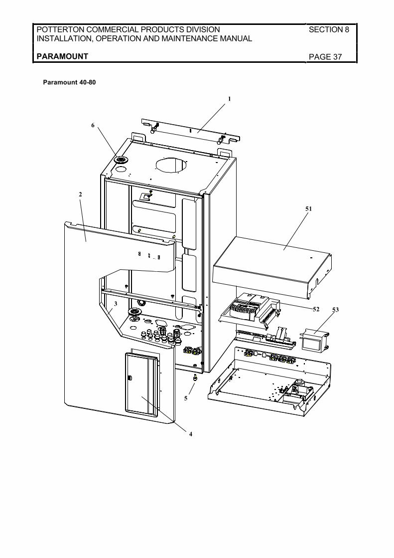
POTTERTON COMMERCIAL PRODUCTS DIVISIONINSTALLATION, OPERATION AND MAINTENANCE MANUAL
SECTION 8
PARAMOUNT PAGE 37
1
51
6
2
3
5352
4
5
Paramount 40-80
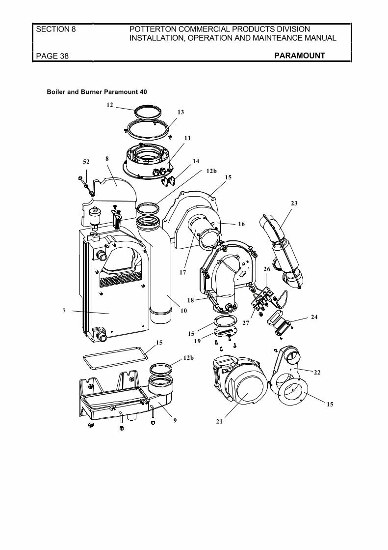
SECTION 8 POTTERTON COMMERCIAL PRODUCTS DIVISION INSTALLATION, OPERATION AND MAINTEANCE MANUAL
PAGE 38 PARAMOUNT
12
13
11
15
16
23
26
24
22
15
21
12b
15
9
17
14
7
8
10
18
19
27
52
15
Boiler and Burner Paramount 40
12b
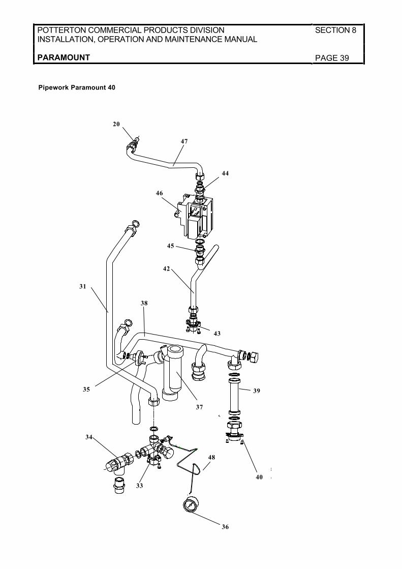
POTTERTON COMMERCIAL PRODUCTS DIVISIONINSTALLATION, OPERATION AND MAINTENANCE MANUAL
SECTION 8
PARAMOUNT PAGE 39
47
20
31
38
37
42
34
33
36
40
35
43
46
44
45
39
48
Pipework Paramount 40
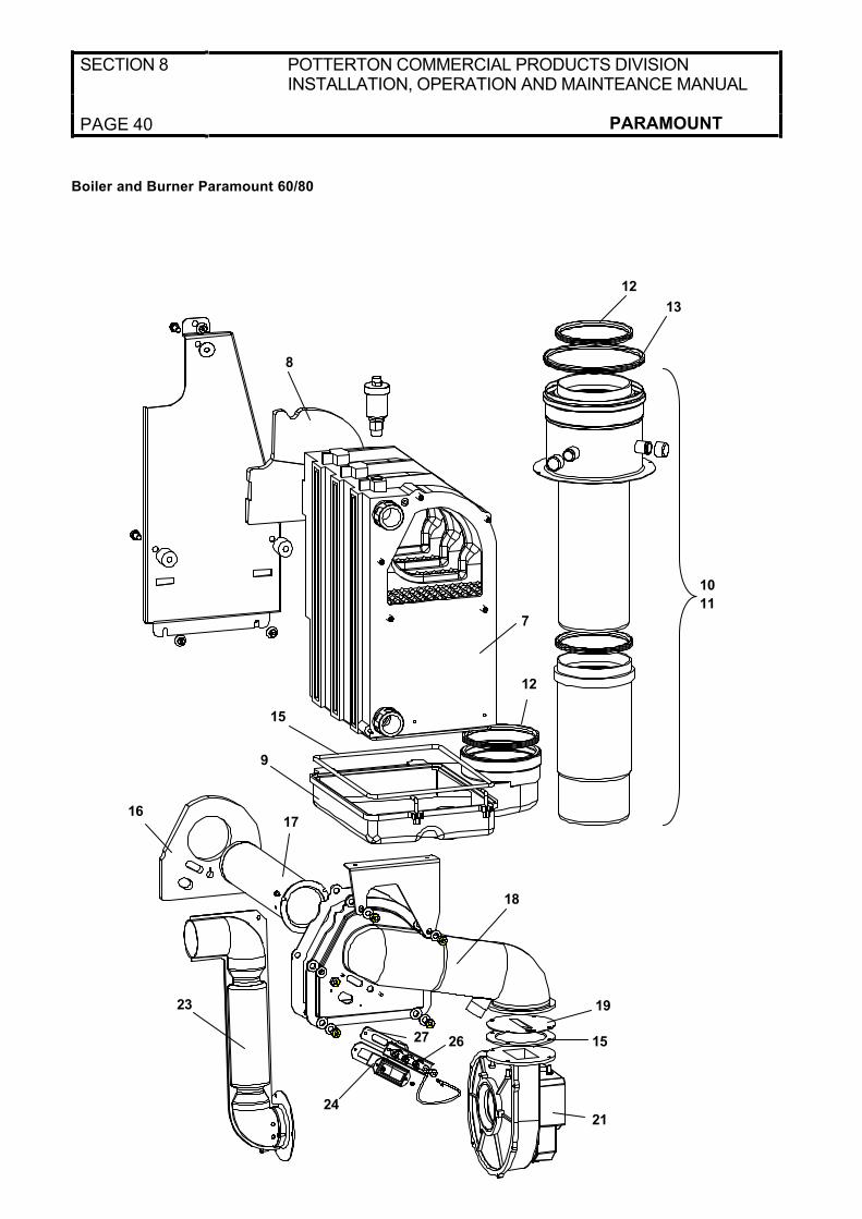
SECTION 8 POTTERTON COMMERCIAL PRODUCTS DIVISION INSTALLATION, OPERATION AND MAINTEANCE MANUAL
PAGE 40 PARAMOUNT
8
12
7
10
11
13
12
15
18
23
1716
19
2627
2124
15
9
Boiler and Burner Paramount 60/80
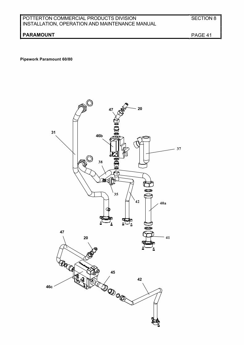
POTTERTON COMMERCIAL PRODUCTS DIVISIONINSTALLATION, OPERATION AND MAINTENANCE MANUAL
SECTION 8
PARAMOUNT PAGE 41
3146b
47 20
42
46c
45
47
20
37
38
4240a
41
35
Pipework Paramount 60/80

SECTION 8 POTTERTON COMMERCIAL PRODUCTS DIVISION INSTALLATION, OPERATION AND MAINTEANCE MANUAL
PAGE 42 PARAMOUNT
Spares Listings Paramount 40, 60, 80
Item Number Part Number Description
Casing
1 988 896 Wall Mounting Plate 40 – 80
2 998 208 Front Door (Round Edges)
3 986 090 Insulation for Front Door
4 986 106 Door for Control
5 986 113 Door Lock Screw
6 986 311 Seal for Air Vent
Boiler & Burner
7 988 582 Heat Exchanger 40kW
7 991 070 Heat Exchanger 60kW
7 991 087 Heat Exchanger 80kW
8 986 670 Inner Insulation of heat exchanger
9 988 599 Condensate Collector 40kW
9 991 094 Condensate Collector 60kW
9 991 100 Condensate Collector 80kW
10 986 144 Flue Pipe 40kW
11 998 239 Flue Adapter 40kW, 80/125mm
10 + 11 991 117 Flue Pipe and adapter 60/80kW
12 998 253 Gasket 80mm 40kW
12 b 972 192 Gasket 70mm 40kW
13 998 260 Gasket 125mm 40kW
12 992 008 Gasket 100mm 60/80kW
13 992 015 Gasket 150mm 60/80kW
14 998 246 Test Screw 40kW
15 986 168 Set of gaskets for heat exchanger and burner
16 986 175 Inner Insulation of burner flange 40kW
16 991 124 Inner insulation of burner flange 60/80kW
17 988 605 Burner Pipe 40kW
17 991 131 Burner Pipe 60kW
17 991 148 Burner Pipe 80kW
18 986 199 Burner Flange 40kW
18 991 155 Burner Flange 60/80kW
19 988 995 Burner Diaphragm 40kW
19 998 437 Burner Diaphragm 60kW
19 993 555 Burner Diaphragm 80kW
20 989 015 Injector 40/80kW gas G20, Ø7.80mm
20 996 112 Injector 60kW gas G20, Ø8.50mm
20 987 677 Injector 40kW propane, Ø5.80mm
20 991 940 Injector 60/80kW propane, Ø6.20mm
21 989 039 Fan 40kW
21 991 186 Fan 60/80kW
22 986 298 Adapter for fan, 40kW
23 986 304 Air inlet pipe, 40kW
23 991 193 Air inlet pipe 60kW
23 998 444 Air inlet pipe 80kW
24 972 239 Silicone Tube
25 972 338 Sight Glass
26 986 328 Ignition and Ionisation unit
27 986 335 Gasket for ignition and ionisation unit
28 972 789 Ignition transformer ZAG 2/230 V for 40kW
28 991 209 Ignition transformer EBI 052F0030 for 60/80kW
Not Shown 986 342 Ignition lead 40kW
Not Shown 991 216 Ignition lead 60/80kW
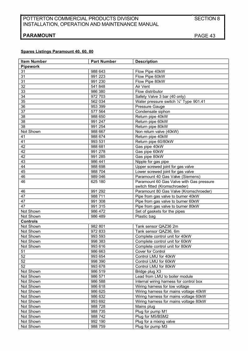
POTTERTON COMMERCIAL PRODUCTS DIVISIONINSTALLATION, OPERATION AND MAINTENANCE MANUAL
SECTION 8
PARAMOUNT PAGE 43
Spares Listings Paramount 40, 60, 80
Item Number Part Number Description
Pipework
31 988 643 Flow Pipe 40kW
31 991 223 Flow Pipe 60kW
31 991 230 Flow Pipe 80kW
32 541 848 Air Vent
33 986 380 Flow distributor
34 972 703 Safety Valve 3 bar (40 only)
35 562 034 Water pressure switch ¼” Type 901.41
36 953 399 Pressure Gauge
37 577 564 Condensate siphon
38 988 650 Return pipe 40kW
38 991 247 Return pipe 60kW
38 991 254 Return pipe 80kW
Not Shown 988 667 Non return valve (40kW)
41 988 674 Return pipe 40kW
41 993 531 Return pipe 60/80kW
42 988 681 Gas pipe 40kW
42 991 278 Gas pipe 60kW
42 991 285 Gas pipe 80kW
43 986 441 Nipple for gas pipe
44 988 698 Upper screwed joint for gas valve
45 988 704 Lower screwed joint for gas valve
46 989 046 Paramount 40 Gas Valve (Siemens)
46 625 180 Paramount 60 Gas Valve with Gas pressure switch fitted (Kromschroeder)
46 991 292 Paramount 80 Gas Valve (Kromschroeder)
47 988 711 Pipe from gas valve to burner 40kW
47 991 308 Pipe from gas valve to burner 60kW
47 991 315 Pipe from gas valve to burner 80kW
Not Shown 986 472 Set of gaskets for the pipes
Not Shown 986 489 Plastic bag
Controls
Not Shown 982 801 Tank sensor QAZ36 2m
Not Shown 972 833 Tank sensor QAZ36, 6m
Not Shown 993 593 Complete control unit for 40kW
Not Shown 998 383 Complete control unit for 60kW
Not Shown 993 616 Complete control unit for 80kW
51 986 663 Cover for Control
52 993 654 Control LMU for 40kW
52 998 390 Control LMU for 60kW
52 993 678 Control LMU for 80kW
Not Shown 986 519 Bridge plug X3
Not Shown 986 571 Lead from LMU to boiler module
Not Shown 986 588 Internal wiring harness for control box
Not Shown 986 618 Wiring harness for low voltage
Not Shown 986 625 Wiring harness for mains voltage 40kW
Not Shown 986 632 Wiring harness for mains voltage 60kW
Not Shown 993 692 Wiring harness for mains voltage 80kW
Not Shown 988 728 Mains plug
Not Shown 988 735 Plug for pump M1
Not Shown 988 742 Plug for M5/BSM2
Not Shown 992 190 Plug for a mixing valve
Not Shown 988 759 Plug for pump M3
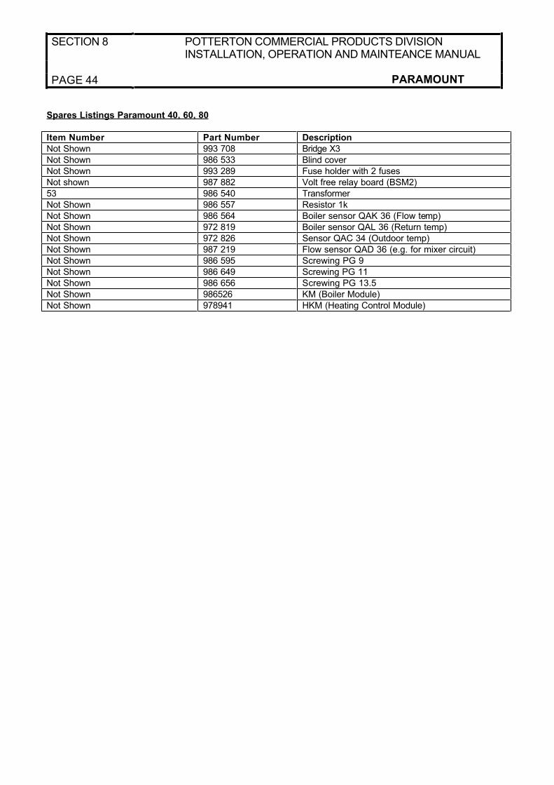
SECTION 8 POTTERTON COMMERCIAL PRODUCTS DIVISION INSTALLATION, OPERATION AND MAINTEANCE MANUAL
PAGE 44 PARAMOUNT
Spares Listings Paramount 40, 60, 80
Item Number Part Number Description
Not Shown 993 708 Bridge X3
Not Shown 986 533 Blind cover
Not Shown 993 289 Fuse holder with 2 fuses
Not shown 987 882 Volt free relay board (BSM2)
53 986 540 Transformer
Not Shown 986 557 Resistor 1k
Not Shown 986 564 Boiler sensor QAK 36 (Flow temp)
Not Shown 972 819 Boiler sensor QAL 36 (Return temp)
Not Shown 972 826 Sensor QAC 34 (Outdoor temp)
Not Shown 987 219 Flow sensor QAD 36 (e.g. for mixer circuit)
Not Shown 986 595 Screwing PG 9
Not Shown 986 649 Screwing PG 11
Not Shown 986 656 Screwing PG 13.5
Not Shown 986526 KM (Boiler Module)
Not Shown 978941 HKM (Heating Control Module)
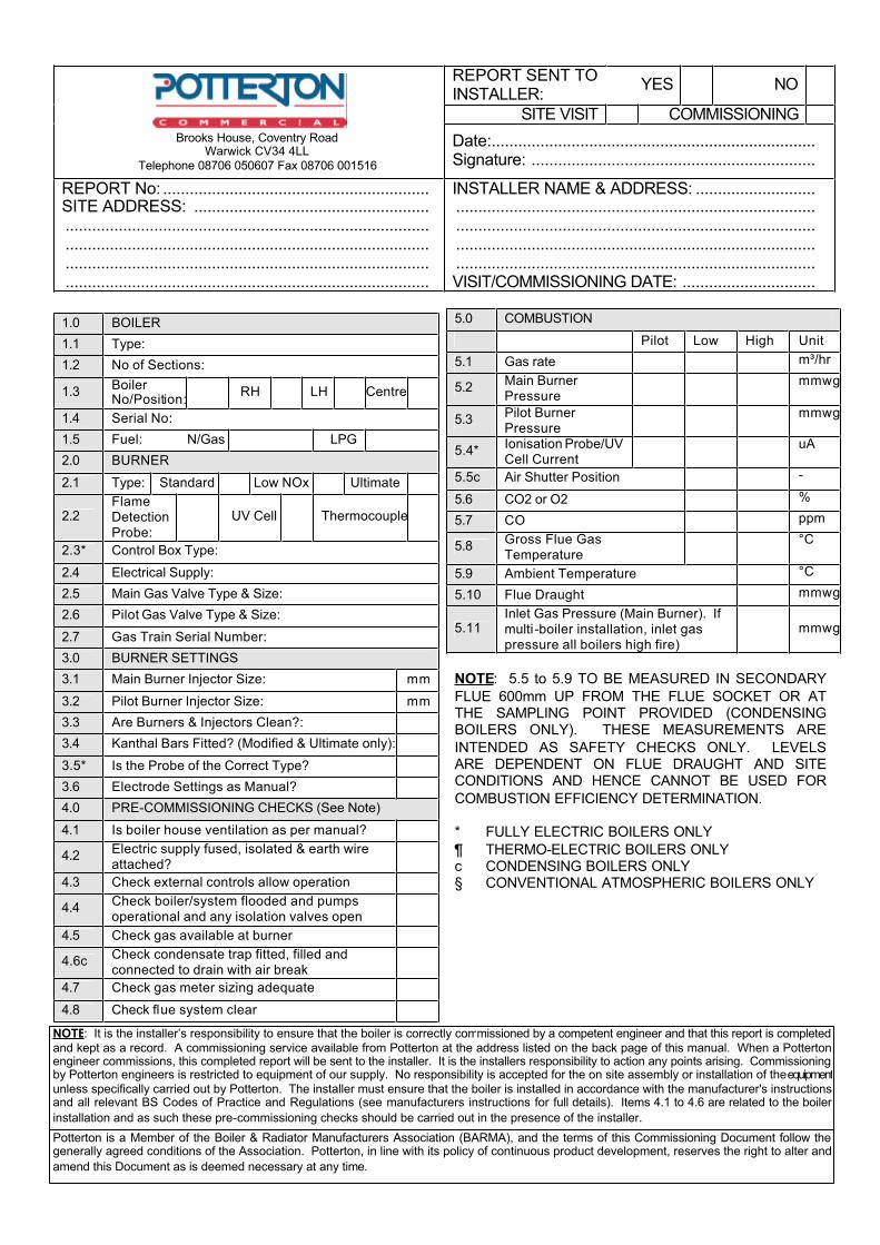
REPORT SENT TOINSTALLER:
YES NO
SITE VISIT COMMISSIONING
Date:.........................................................................Signature:................................................................
REPORT No:............................................................SITE ADDRESS: .............................................................................................................................................................................................................................................................................................................................................................................................
INSTALLER NAME & ADDRESS:...............................................................................................................................................................................................................................................................................................................................................................VISIT/COMMISSIONING DATE: ..............................
1.0 BOILER
1.1 Type:
1.2 No of Sections:
1.3BoilerNo/Position:
RH LH Centre
1.4 Serial No:
1.5 Fuel: N/Gas LPG
2.0 BURNER
2.1 Type: Standard Low NOx Ultimate
2.2FlameDetectionProbe:
UV Cell Thermocouple
2.3* Control Box Type:
2.4 Electrical Supply:
2.5 Main Gas Valve Type & Size:
2.6 Pilot Gas Valve Type & Size:
2.7 Gas Train Serial Number:
3.0 BURNER SETTINGS
3.1 Main Burner Injector Size: mm
3.2 Pilot Burner Injector Size: mm
3.3 Are Burners & Injectors Clean?:
3.4 Kanthal Bars Fitted? (Modified & Ultimate only):
3.5* Is the Probe of the Correct Type?
3.6 Electrode Settings as Manual?
4.0 PRE-COMMISSIONING CHECKS (See Note)
4.1 Is boiler house ventilation as per manual?
4.2Electric supply fused, isolated & earth wire attached?
4.3 Check external controls allow operation
4.4Check boiler/system flooded and pumps operational and any isolation valves open
4.5 Check gas available at burner
4.6cCheck condensate trap fitted, filled and connected to drain with air break
4.7 Check gas meter sizing adequate
4.8 Check flue system clear
5.0 COMBUSTION
Pilot Low High Unit
5.1 Gas rate m³/hr
5.2Main Burner Pressure
mmwg
5.3Pilot Burner Pressure
mmwg
5.4*Ionisation Probe/UV Cell Current
uA
5.5c Air Shutter Position -
5.6 CO2 or O2 %
5.7 CO ppm
5.8Gross Flue Gas Temperature
°C
5.9 Ambient Temperature °C
5.10 Flue Draught mmwg
5.11Inlet Gas Pressure (Main Burner). If multi -boiler installation, inlet gas pressure all boilers high fire)
mmwg
NOTE: 5.5 to 5.9 TO BE MEASURED IN SECONDARY
FLUE 600mm UP FROM THE FLUE SOCKET OR ATTHE SAMPLING POINT PROVIDED (CONDENSINGBOILERS ONLY). THESE MEASUREMENTS ARE
INTENDED AS SAFETY CHECKS ONLY. LEVELSARE DEPENDENT ON FLUE DRAUGHT AND SITECONDITIONS AND HENCE CANNOT BE USED FOR
COMBUSTION EFFICIENCY DETERMINATION.
* FULLY ELECTRIC BOILERS ONLY
¶ THERMO-ELECTRIC BOILERS ONLYc CONDENSING BOILERS ONLY§ CONVENTIONAL ATMOSPHERIC BOILERS ONLY
NOTE: It is the installer’s responsibility to ensure that the boiler is correctly commissioned by a competent engineer and that this report is completed
and kept as a record. A commissioning service available from Potterton at the address listed on the back page of this manual. W hen a Potterton engineer commissions, this completed report will be sent to the installer. It is the installers responsibility to action any points arising. Commissioning by Potterton engineers is restricted to equipment of our supply. No responsibility is accepted for the on site assembly or installation of the equipment
unless specifically carried out by Potterton. The installer must ensure that the boiler is installed in accordance with the manufacturer's instructions and all relevant BS Codes of Practice and Regulations (see manufacturers instructions for full details). Items 4.1 to 4.6 are related to the boiler
installation and as such these pre-commissioning checks should be carried out in the presence of the installer.
Potterton is a Member of the Boiler & Radiator Manufacturers Association (BARMA), and the terms of this Commissioning Document follow the generally agreed conditions of the Association. Potterton, in line with its policy of continuous product development, reserves the right to alter and
amend this Document as is deemed necessary at any time.
Brooks House, Coventry RoadW arwick CV34 4LL
Telephone 08706 050607 Fax 08706 001516
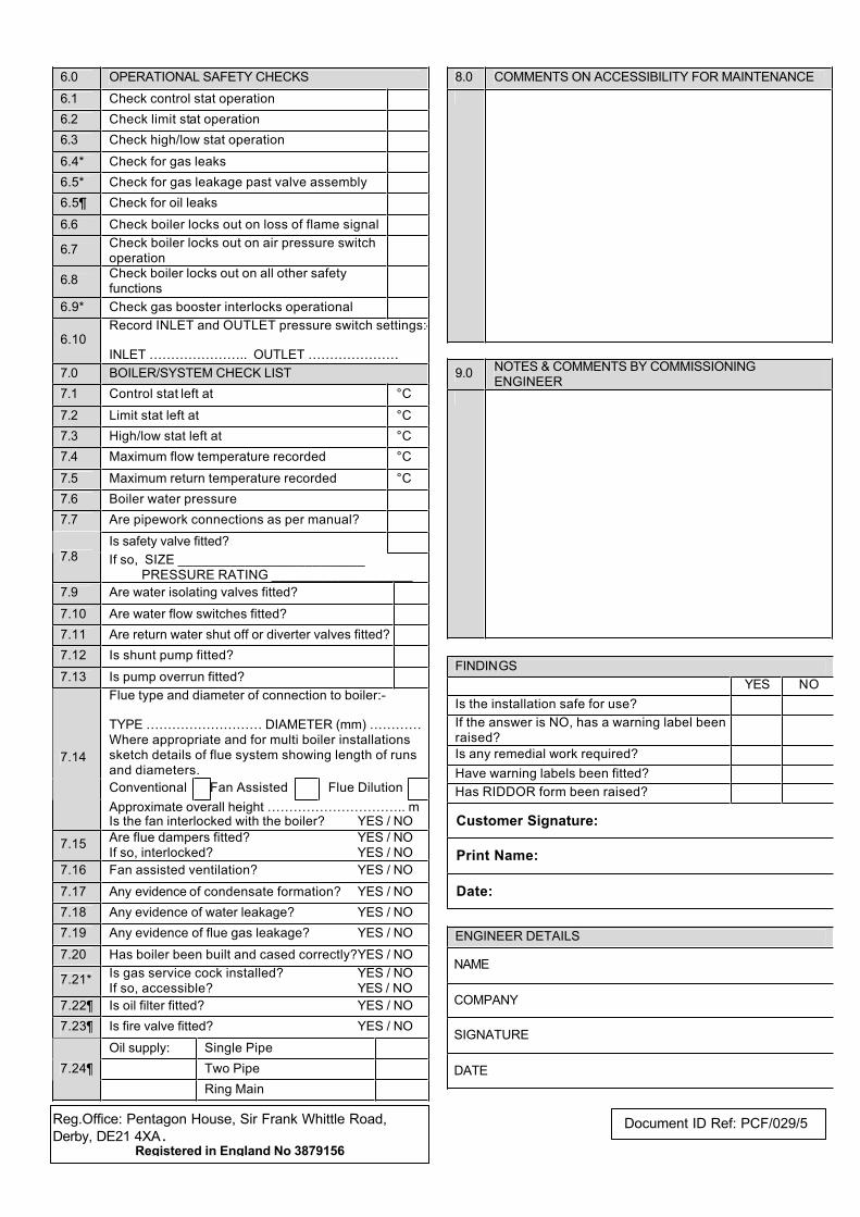
6.0 OPERATIONAL SAFETY CHECKS
6.1 Check control stat operation
6.2 Check limit stat operation
6.3 Check high/low stat operation
6.4* Check for gas leaks
6.5* Check for gas leakage past valve assembly
6.5¶ Check for oil leaks
6.6 Check boiler locks out on loss of flame signal
6.7Check boiler locks out on air pressure switchoperation
6.8Check boiler locks out on all other safety functions
6.9* Check gas booster interlocks operational
6.10Record INLET and OUTLET pressure switch settings:-
INLET … … … … … … … .. OUTLET … … … … … … …
7.0 BOILER/SYSTEM CHECK LIST
7.1 Control stat left at °C
7.2 Limit stat left at °C
7.3 High/low stat left at °C
7.4 Maximum flow temperature recorded °C
7.5 Maximum return temperature recorded °C
7.6 Boiler water pressure
7.7 Are pipework connections as per manual?
Is safety valve fitted?7.8 If so, SIZE _________________________
PRESSURE RATING ___________________
7.9 Are water isolating valves fitted?
7.10 Are water flow switches fitted?
7.11 Are return water shut off or diverter valves fitted?
7.12 Is shunt pump fitted?
7.13 Is pump overrun fitted?
Flue type and diameter of connection to boiler:-
TYPE … … … … … … … … … DIAMETER (mm) … … … …Where appropriate and for multi boiler installations sketch details of flue system showing length of runs and diameters.
Conventional Fan Assisted Flue Dilution
7.14
Approximate overall height … … … … … … … … … … .. mIs the fan interlocked with the boiler? YES / NO
7.15Are flue dampers fitted? YES / NOIf so, interlocked? YES / NO
7.16 Fan assisted ventilation? YES / NO
7.17 Any evidence of condensate formation? YES / NO
7.18 Any evidence of water leakage? YES / NO
7.19 Any evidence of flue gas leakage? YES / NO
7.20 Has boiler been built and cased correctly?YES / NO
7.21*Is gas service cock installed? YES / NOIf so, accessible? YES / NO
7.22¶ Is oil filter fitted? YES / NO
7.23¶ Is fire valve fitted? YES / NO
Oil supply: Single Pipe
Two Pipe7.24¶
Ring Main
8.0 COMMENTS ON ACCESSIBILITY FOR MAINTENANCE
9.0NOTES & COMMENTS BY COMMISSIONING ENGINEER
FINDINGS
YES NO
Is the installation safe for use?
If the answer is NO, has a warning label been raised?
Is any remedial work required?
Have warning labels been fitted?
Has RIDDOR form been raised?
Customer Signature:
Print Name:
Date:
ENGINEER DETAILS
NAME
COMPANY
SIGNATURE
DATE
Reg.Office: Pentagon House, Sir Frank Whittle Road,
Derby, DE21 4XA .Registered in England No 3879156
Document ID Ref: PCF/029/5
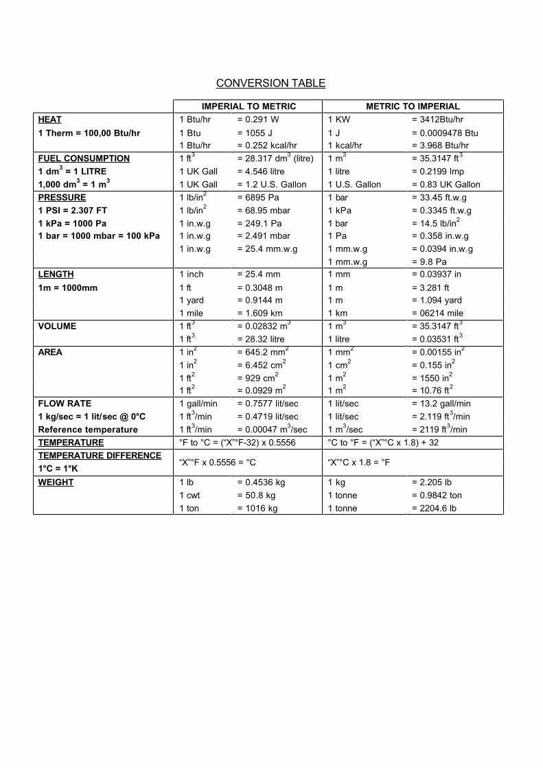
CONVERSION TABLE
IMPERIAL TO METRIC METRIC TO IMPERIAL
HEAT 1 Btu/hr = 0.291 W 1 KW = 3412Btu/hr
1 Therm = 100,00 Btu/hr 1 Btu = 1055 J 1 J = 0.0009478 Btu
1 Btu/hr = 0.252 kcal/hr 1 kcal/hr = 3.968 Btu/hr
FUEL CONSUMPTION 1 ft3
= 28.317 dm3 (litre) 1 m
3= 35.3147 ft
3
1 dm3 = 1 LITRE 1 UK Gall = 4.546 litre 1 litre = 0.2199 Imp
1,000 dm3 = 1 m
31 UK Gall = 1.2 U.S. Gallon 1 U.S. Gallon = 0.83 UK Gallon
PRESSURE 1 lb/in2
= 6895 Pa 1 bar = 33.45 ft.w.g
1 PSI = 2.307 FT 1 lb/in2
= 68.95 mbar 1 kPa = 0.3345 ft.w.g
1 kPa = 1000 Pa 1 in.w.g = 249.1 Pa 1 bar = 14.5 lb/in2
1 bar = 1000 mbar = 100 kPa 1 in.w.g = 2.491 mbar 1 Pa = 0.358 in.w.g
1 in.w.g = 25.4 mm.w.g 1 mm.w.g = 0.0394 in.w.g
1 mm.w.g = 9.8 Pa
LENGTH 1 inch = 25.4 mm 1 mm = 0.03937 in
1m = 1000mm 1 ft = 0.3048 m 1 m = 3.281 ft
1 yard = 0.9144 m 1 m = 1.094 yard
1 mile = 1.609 km 1 km = 06214 mile
VOLUME 1 ft3
= 0.02832 m3
1 m3
= 35.3147 ft3
1 ft3
= 28.32 litre 1 litre = 0.03531 ft3
AREA 1 in2
= 645.2 mm2
1 mm2
= 0.00155 in2
1 in2
= 6.452 cm2
1 cm2
= 0.155 in2
1 ft2
= 929 cm2
1 m2
= 1550 in2
1 ft2
= 0.0929 m2
1 m2
= 10.76 ft2
FLOW RATE 1 gall/min = 0.7577 lit/sec 1 lit/sec = 13.2 gall/min
1 kg/sec = 1 lit/sec @ 0°C 1 ft3/min = 0.4719 lit/sec 1 lit/sec = 2.119 ft
3/min
Reference temperature 1 ft3/min = 0.00047 m
3/sec 1 m
3/sec = 2119 ft
3/min
TEMPERATURE °F to °C = (“X”°F-32) x 0.5556 °C to °F = (“X”°C x 1.8) + 32
TEMPERATURE DIFFERENCE
1°C = 1°K“X”°F x 0.5556 = °C “X”°C x 1.8 = °F
W EIGHT 1 lb = 0.4536 kg 1 kg = 2.205 lb
1 cwt = 50.8 kg 1 tonne = 0.9842 ton
1 ton = 1016 kg 1 tonne = 2204.6 lb


For further details on Potterton Commercial boiler products contact the following:-
Potterton Commercial Products Division Tel: (08706) 050607
Brooks House Fax: (01926) 001516Coventry Road Sales Direct Line: (08706) 001991WARWICK Technical Direct Line: (08706) 002322
CV34 4LL e-mail: commercial@ potterton.co.ukWeb Site: www.pottertoncommercial.co.uk
Our service organisation covers the whole of the U.K. to look after your needs for all Potterton Commercial Products.We are also able to offer our services for other manufacturers products.
SOUTHERN REGION NORTHERN REGIONPotterton Commercial Service Dept Potterton Commercial Service Dept
Unit 2 Borehamwood Enterprise Centre Unit 102, Batley Enterprise CentreTheobald Street, 513 Bradford RoadBOREHAMWOOD BATLEY
Herts WD6 4RU West Yorkshire WF17 8JYTel: (08702) 412759 Tel: (08702) 412759Fax: (02082) 072466 Fax: (01924) 420276
Our service offices offer a wide range of specialised services including:-
• Boiler Site Assembly
• Burner Commissioning for all Fuels
• Boiler Maintenance & Maintenance Contracts
• Breakdown & Repair Services
• Boiler Dismantling & Re-Jointing
• Burner & Boiler Replacement
• Oil/Gas Conversions
• System Conditioning
• Water Treatment & Descaling
• Packaged Units
Potterton Commercial spares are available nationwide through the Potterton Interpart network. Alternatively please contact:-
interpart
Brooks House, Coventry Road, Warwick - Telephone: 08706 00454 Fax: 08706 000545
COMMERCIAL SALES & TECHNICAL ENQUIRIES
COMMERCIAL SERVICE OFFICES
SPARES
“All descriptions and illustrations contained in this leaflet have been carefully prepared but we reserve the right to make
changes and improvements in our product which may affect the accuracy of the information contained in this leaflet”
Baxi Heating Ltd Reg. Office: Sir Frank Whittle Road, Derby DE321 4XA, Registered in England No. 3879156
Publication Number: M/PARA/1203
393473 05.05 DB/PH
h e a t i n g s p e c i a l i s t s
A Baxi Group Company