


Languages
Pages
Legal

Logic and Digital LogicLogic and Digital LogicCPUsCPUs
Patrice KoehlComputer Science
UC Davis
Basic Concepts (part II)Basic Concepts (part II)
Logic◦Proposition◦Operation on propositions
Digital Logic- The transistor- Gates
CPU◦Order of operations◦Speed
Basic Concepts (part II)Basic Concepts (part II)
Logic◦Proposition◦Operation on propositions
Digital Logic- The transistor- Gates
CPU◦Order of operations◦Speed
Logic: proposition
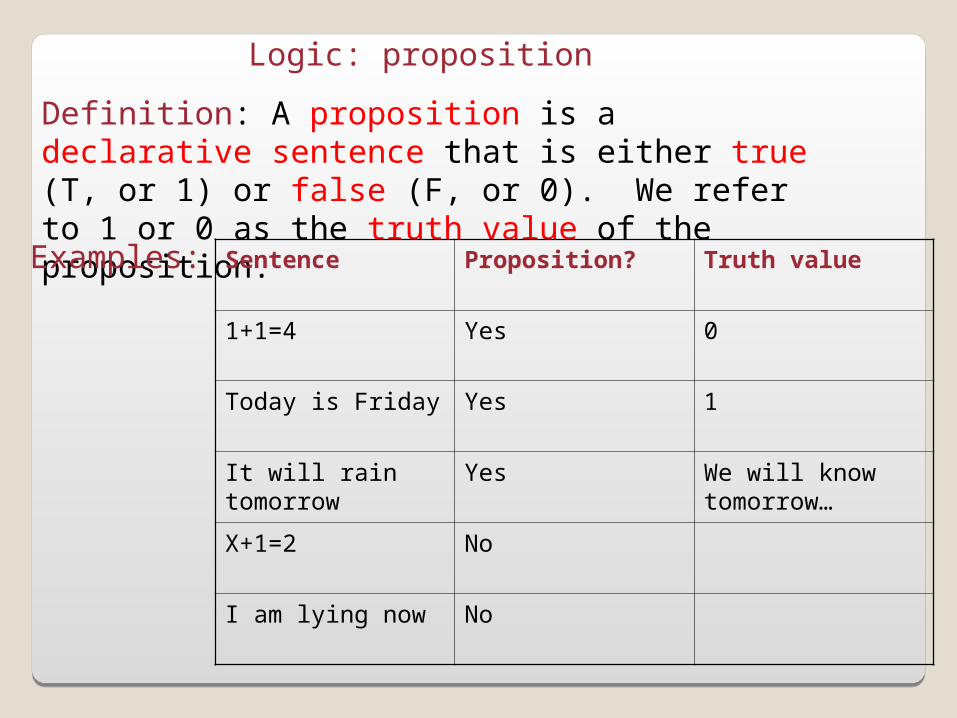
Definition: A proposition is a declarative sentence that is either true (T, or 1) or false (F, or 0). We refer to 1 or 0 as the truth value of the proposition.
Examples: Sentence Proposition? Truth value
1+1=4 Yes 0
Today is Friday Yes 1
It will rain tomorrow Yes We will know tomorrow…
X+1=2 No
I am lying now No
Logic: compound propositions
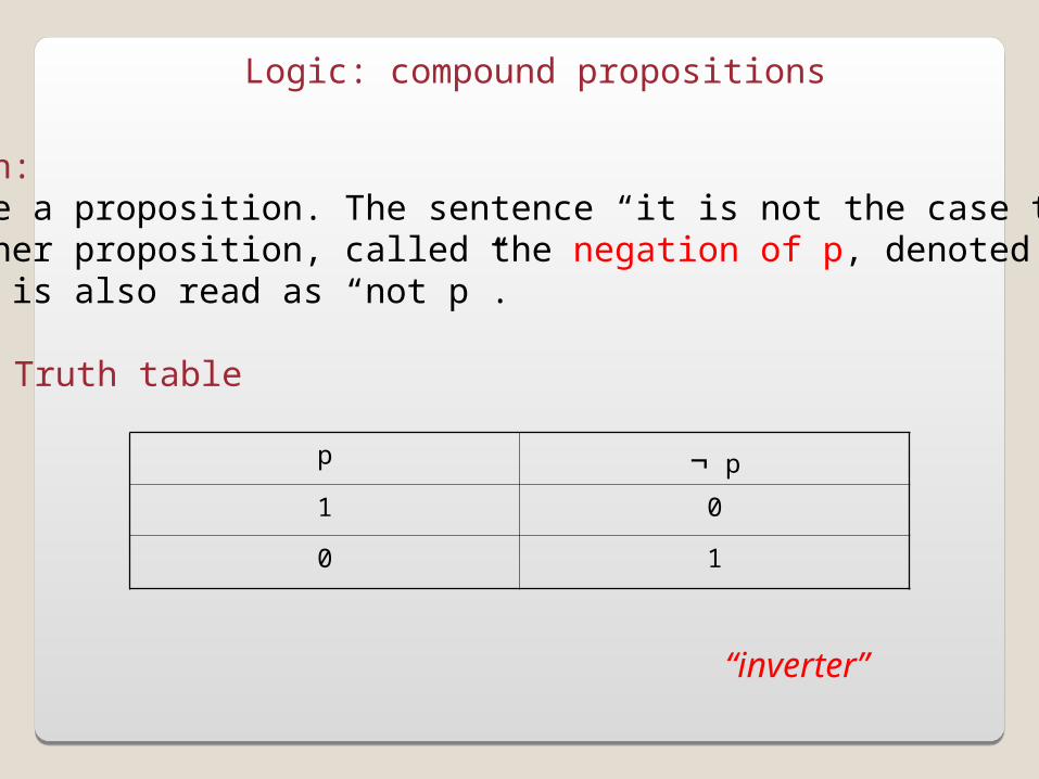
Negation:Let p be a proposition. The sentence “it is not the case that p” is another proposition, called the negation of p, denoted ¬p or~p. It is also read as “not p”.
Truth table
p ¬ p
1 0
0 1
“inverter”
Logic: compound propositions
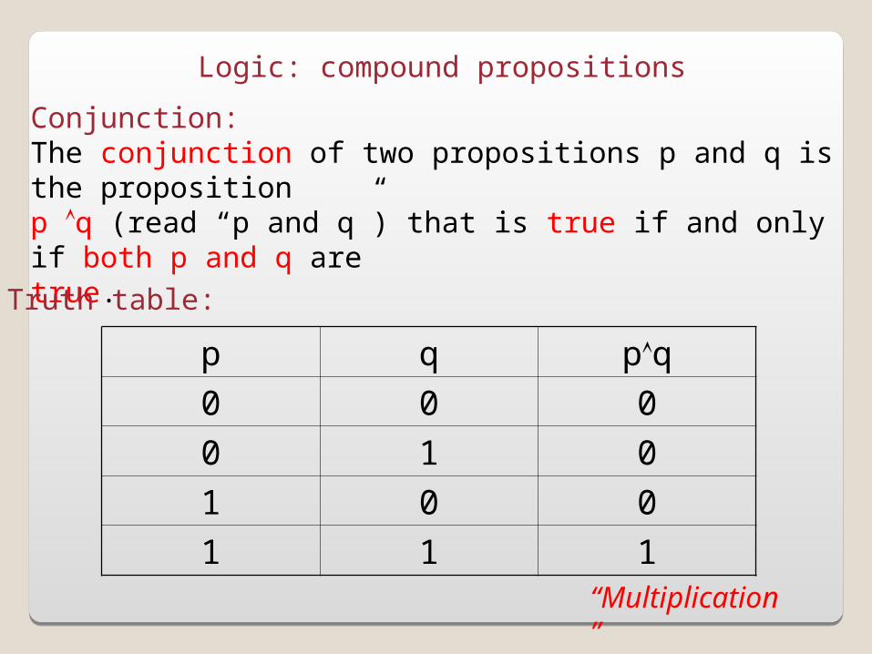
Conjunction:The conjunction of two propositions p and q is the propositionp q (read “p and q”) that is true if and only if both p and q aretrue.
Truth table:
p q pq
0 0 0
0 1 0
1 0 0
1 1 1“Multiplication”
Logic: compound propositions
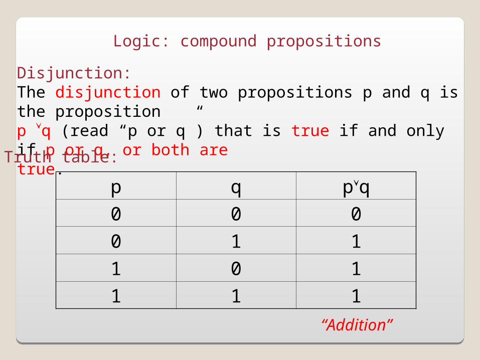
Disjunction:The disjunction of two propositions p and q is the propositionp q (read “p or q”) that is true if and only if p or q, or both aretrue.
Truth table:
p q pq
0 0 0
0 1 1
1 0 1
1 1 1
“Addition”
Basic Concepts (part II)Basic Concepts (part II)
Logic◦Proposition◦Operation on propositions
Digital Logic- The transistor- Gates
CPU◦Order of operations◦Speed
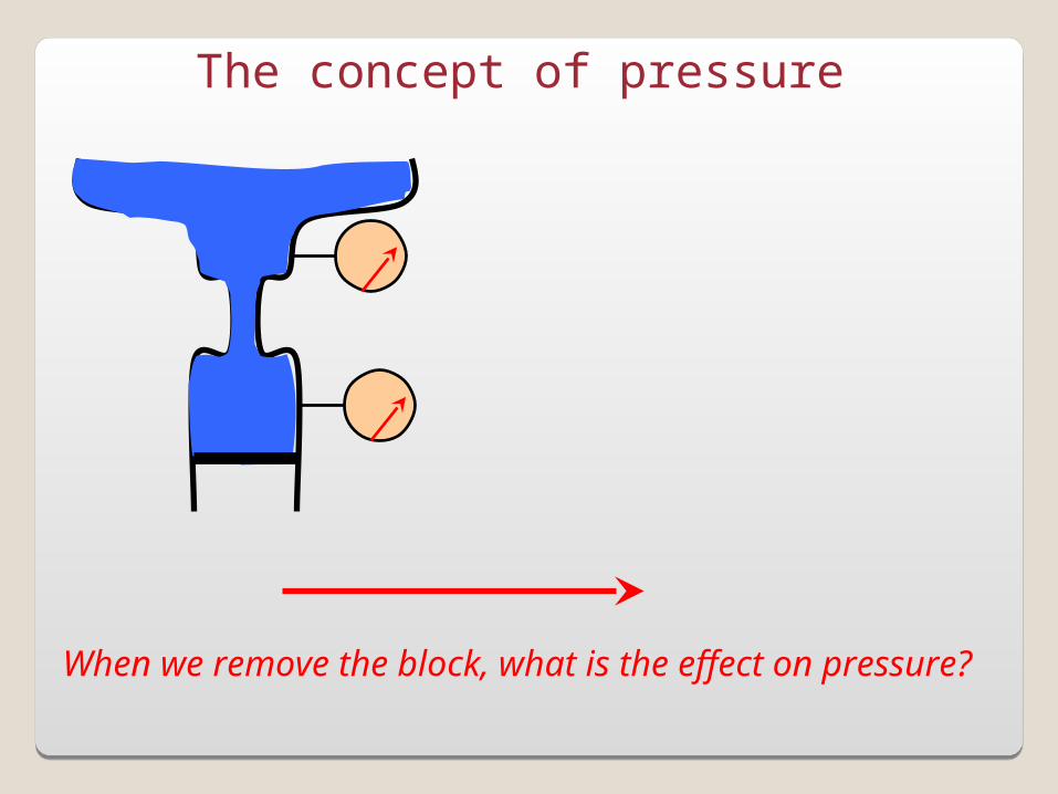
The concept of pressure
When we remove the block, what is the effect on pressure?
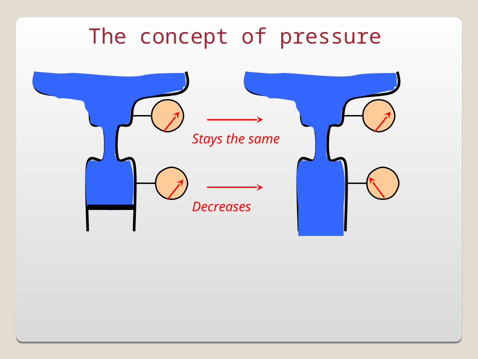
The concept of pressure
Stays the same
Decreases
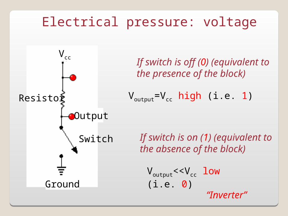
Electrical pressure: voltage
Vcc
Ground
Resistor
Switch
If switch is off (0) (equivalent tothe presence of the block)
Output
Voutput=Vcc high (i.e. 1)
If switch is on (1) (equivalent tothe absence of the block)
Voutput<<Vcc low (i.e. 0)
“Inverter”
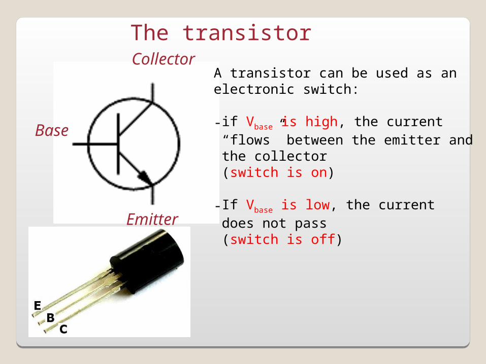
The transistor
Base
Collector
Emitter
A transistor can be used as anelectronic switch:
-if Vbase is high, the current “flows” between the emitter and the collector (switch is on)
-If Vbase is low, the current does not pass (switch is off)
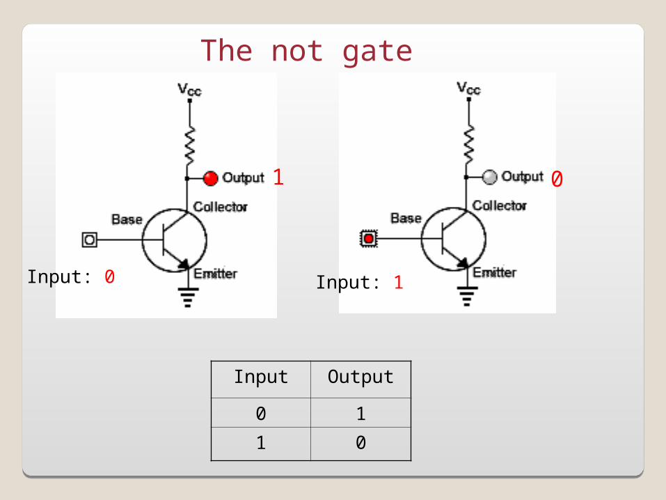
The not gate
Input: 0
1
Input: 1
0
Input Output
0 1
1 0
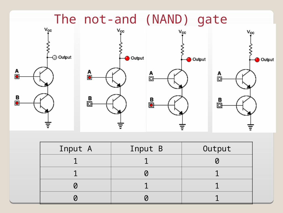
Input A Input B Output
1 1 0
1 0 1
0 1 1
0 0 1
The not-and (NAND) gate
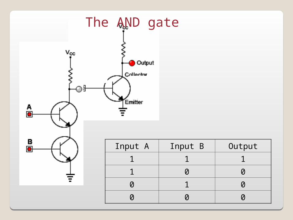
The AND gate
Input A Input B Output
1 1 1
1 0 0
0 1 0
0 0 0
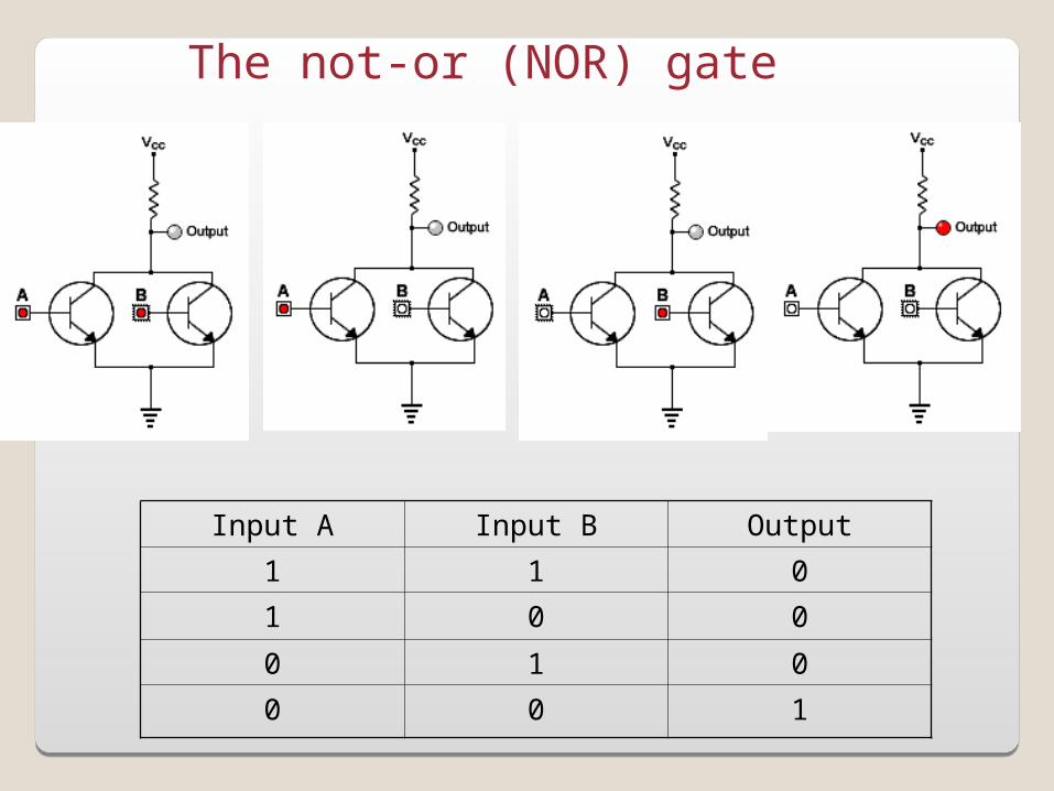
The not-or (NOR) gate
Input A Input B Output
1 1 0
1 0 0
0 1 0
0 0 1
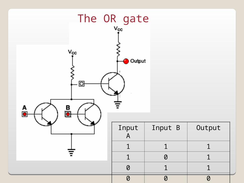
The OR gate
Input A Input B Output
1 1 1
1 0 1
0 1 1
0 0 0
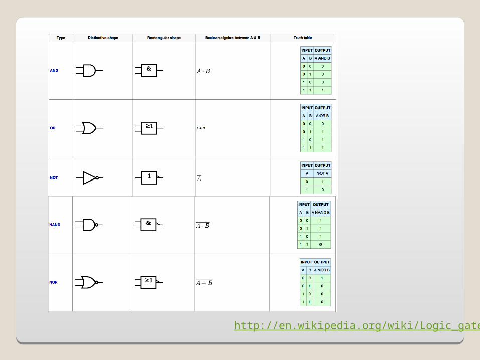
http://en.wikipedia.org/wiki/Logic_gate

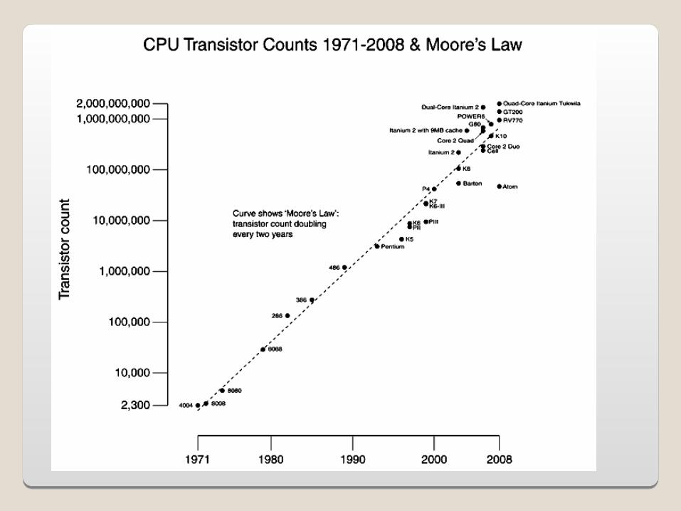
Integrated Circuit- A computer central processing unit (CPU) is an electronic circuit combining millions of these logical digital gates and other electronic components.
-While the transistor was key to the development of computers, another major step was the possibility to miniaturized to the extreme the design of these electronic circuits: this was made possible by the invention of the Integrated Circuit (or IC, microcircuits, microchips, silicon chips or chips).
There has been several generations of IC:-SSI: small scale integration-MSI: medium scale integration-LSI: large scale integration-VLSI: very large scale integration
-Moore’s law (1965):“The complexity for minimum component costs has increased at a rate of roughly a factor of two per year. Certainly over the short term this rate can be expected to continue”
Basic Concepts (part II)Basic Concepts (part II)
Logic◦Proposition◦Operation on propositions
Digital Logic- The transistor- Gates
CPU◦Order of operations◦Speed
ALU Control
Memory
Input
Output
CPU
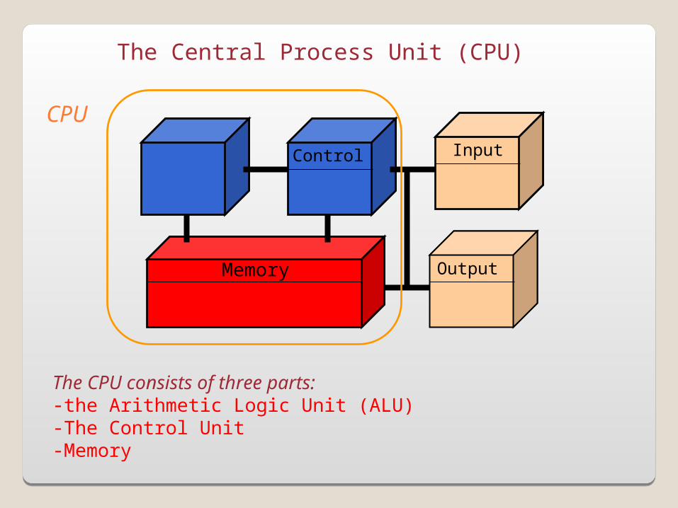
The Central Process Unit (CPU)
The CPU consists of three parts:-the Arithmetic Logic Unit (ALU)-The Control Unit-Memory
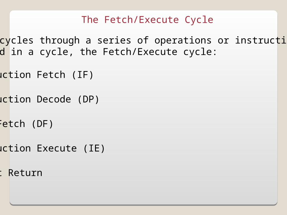
The Fetch/Execute Cycle
The CPU cycles through a series of operations or instructions,organized in a cycle, the Fetch/Execute cycle:
1. Instruction Fetch (IF)
2. Instruction Decode (DP)
3. Data Fetch (DF)
4. Instruction Execute (IE)
5. Result Return
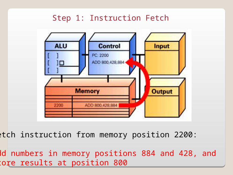
Step 1: Instruction Fetch
Fetch instruction from memory position 2200:
Add numbers in memory positions 884 and 428, andstore results at position 800
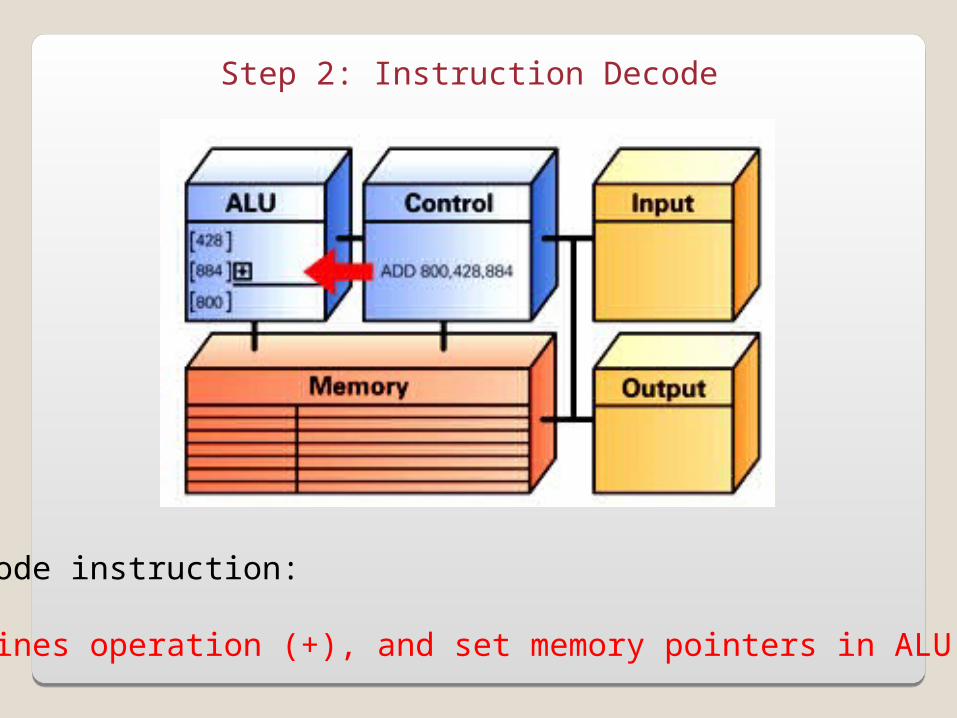
Step 2: Instruction Decode
Decode instruction:
Defines operation (+), and set memory pointers in ALU
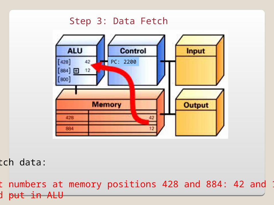
Step 3: Data Fetch
Fetch data:
Get numbers at memory positions 428 and 884: 42 and 12and put in ALU
PC: 2200
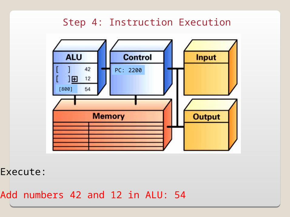
Step 4: Instruction Execution
Execute:
Add numbers 42 and 12 in ALU: 54
PC: 2200
[800]
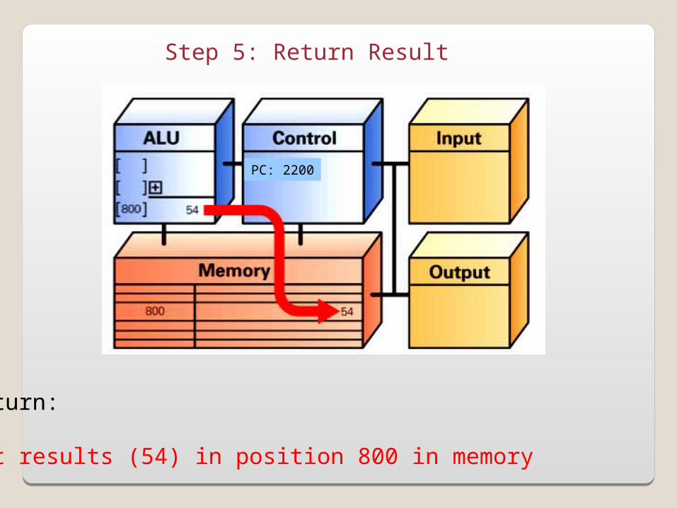
Step 5: Return Result
Return:
Put results (54) in position 800 in memory
PC: 2200
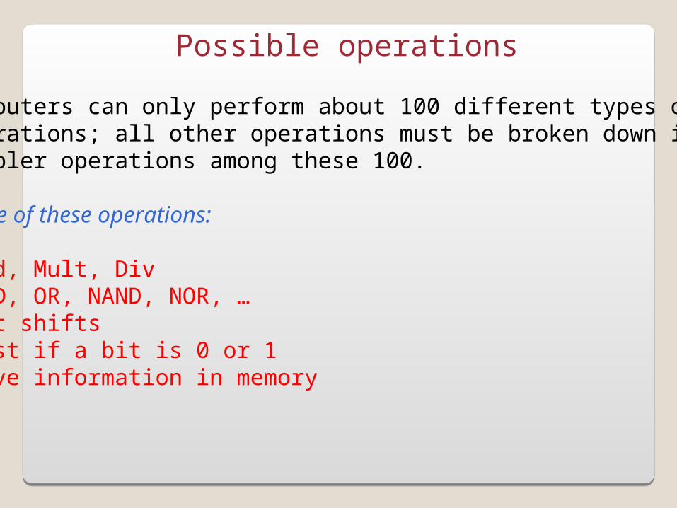
Possible operations
Computers can only perform about 100 different types ofoperations; all other operations must be broken down intosimpler operations among these 100.
Some of these operations:
-Add, Mult, Div-AND, OR, NAND, NOR, …-Bit shifts-Test if a bit is 0 or 1-Move information in memory-…
Repeating the F/E cycle
Computers get their impressive capabilities by performingmany of these F/E cycles per second.
The computer clock determines the rate of F/E cycles persecond; it is now expressed in GHz, i.e. in billions of cyclesper seconds!
Note that the rate given is not an exact measurement.
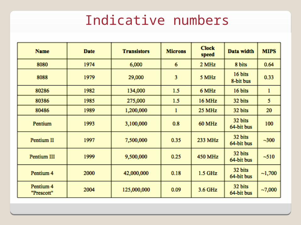
Indicative numbers
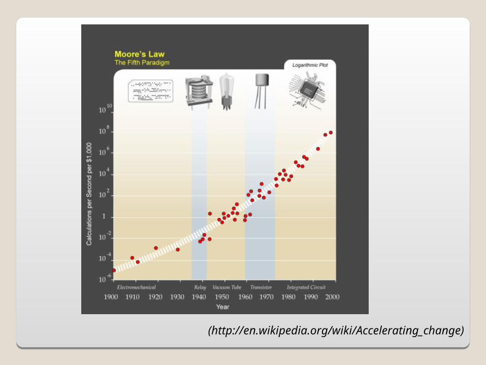
(http://en.wikipedia.org/wiki/Accelerating_change)
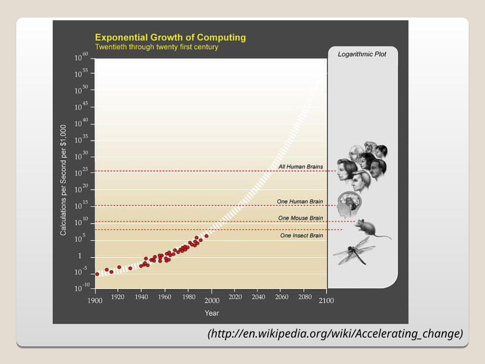
(http://en.wikipedia.org/wiki/Accelerating_change)
Top Related