


Languages
Pages
Legal

Design with MicroprocessorsLecture 1
Year 3 CS
Academic year 2017/2018
1st Semester
Lecturer: Radu Dănescu

Introduction
Objectives
• Know, understand and use concepts like: microprocessor, bus, memory system,
i/o system and data transfer methods, interfaces.
• Analyze and design systems with microprocessors
Prerequisites
• Logic Design, Digital System Design, Computer Architecture, Assembly
Language Programming, Computer Programming (C/C++)
Discipline structure
• 2C + 1L + 1P / week
Lecture structure
• Part 1 – ATMEL (ATmega2560, Arduino) and applications
• Part 2 –microprocesor systems design issues (using the x86 family)
Topic for lab works
• Hands on work using Arduino boards (ATmega2560 (MEGA2560),
ATmega328P(Uno)) and multiple peripheral modules
Bibliography Lecture slides, available on the website:
http://users.utcluj.ro/~rdanescu/teaching_pmp.html
Microcontrollers overview
G. Grindling, B. Weiss, Introduction to Microcontrollers, Vienna Institute of Technology,
2007.
https://ti.tuwien.ac.at/ecs/teaching/courses/mclu/theory-material/Microcontroller.pdf
Atmel AVR, Arduino
M. A. Mazidi, S. Naimi, S. Naimi, The AVR Microcontroller and Embedded Systems Using Assembly And C, 1-st Edition, Prentice Hall, 2009.
Michael Margolis, Arduino Cookbook, 2-nd Edition, O’Reilly, 2012.
8086 family
Barry B. Brey, The Intel Microprocessors: 8086/8088, 80186,80286, 80386 and 80486. Architecture, Programming, and Interfacing, 4-rd edition, Prentice Hall, 1997
S. Nedevschi, L. Todoran, „Microprocesoare”, published by UTC-N, 1995.
Additional documents
Data sheets Atmel, Intel etc, Arduino tutorials: http://arduino.cc/en/Tutorial/HomePage
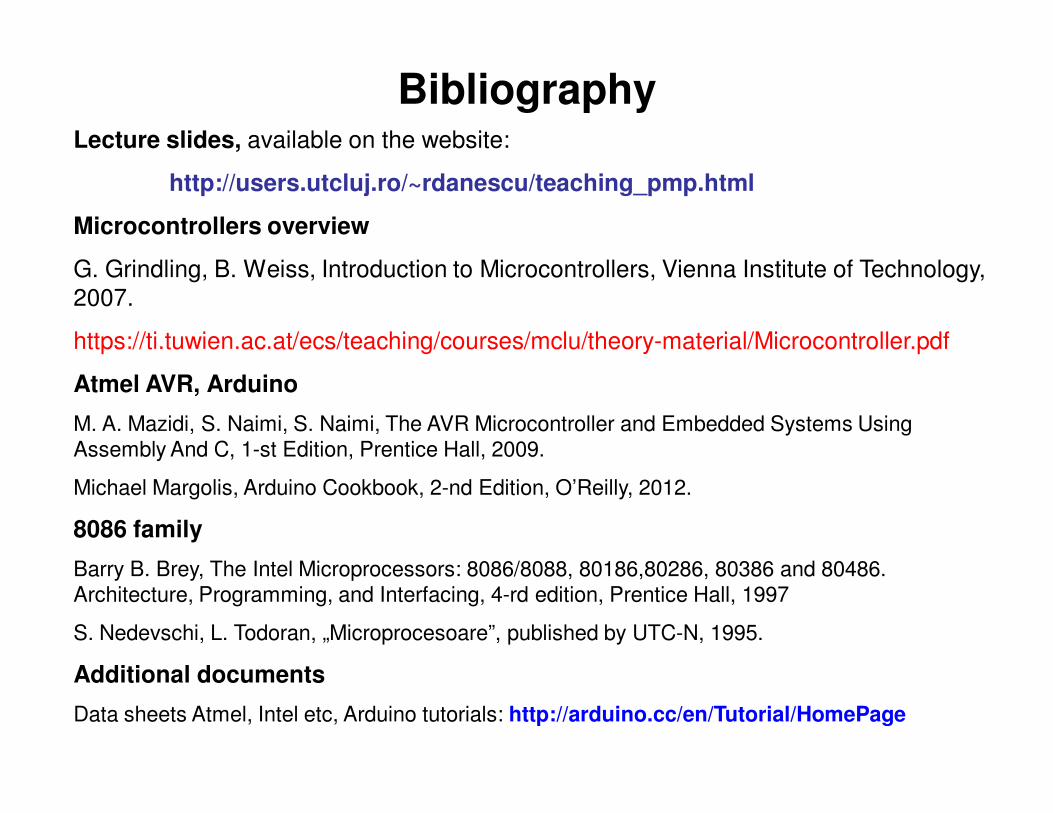
Evaluation
Evaluation: exam mark (E) + lab/project mark (LP)
if (LP > = 5) AND (E > = 4.5)
Final_mark = 0.5 *LP + 0.5 * E
else
Final_mark = 4 OR Absent
Bonus - can be awarded for exceptional activity during lecture/lab, or for
participation in student competitions.

What is a microprocessor
A microprocessor is an integrated circuit that includes all or most of the
functions of a Central Processing Unit.
A Central Processing Unit (CPU) is a logic machine that can execute
computer programs.
The program is a sequence of instructions, stored in a memory. The
instructions are usually executed in four steps: reading the instruction (fetch),
decoding the instructions (decode), executing the instruction (execute), and
writing the results (write back).
Intel 80486DX2 , interior Intel 80486DX2 – external view

Short history
4 bit microprocessors: Intel's 4004 (1971), the Texas Instruments (TI) TMS
1000, and Garrett AiResearch's Central Air Data Computer (CADC).
8 bit microprocessors: 8008 (1972), the world's first 8-bit microprocessor.
These processors are the precursors to the very successful Intel 8080
(1974), Zilog Z80 (1976), and derivative Intel 8-bit processors. The
competing Motorola 6800 was released August 1974. Its architecture was
cloned and improved in the MOS Technology 6502 in 1975, rivaling the Z80
in popularity during the 1980s
16 bit (Intel 8086, 8088, 80186, 80286, 8086 SX, TMS 9900)
32 bit (MC68000, Intel 80386DX, 80486DX, Pentium, MIPS R2000 (1984)
and R3000 (1989) etc.)
64 bit (most of nowadays microprocessors)
Types:
RISC: MIPS (R2000, R3000, R4000), Motorola 88000, ATmega (Atmel)
CISC: VAX, PDP-11, Motorola 68000, Intel x86 (each instruction can execute
several low-level operations, such as a load from memory, an arithmetic operation, and a memory store, all in a single instruction)
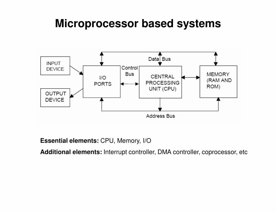
Microprocessor based systems
Essential elements: CPU, Memory, I/O
Additional elements: Interrupt controller, DMA controller, coprocessor, etc
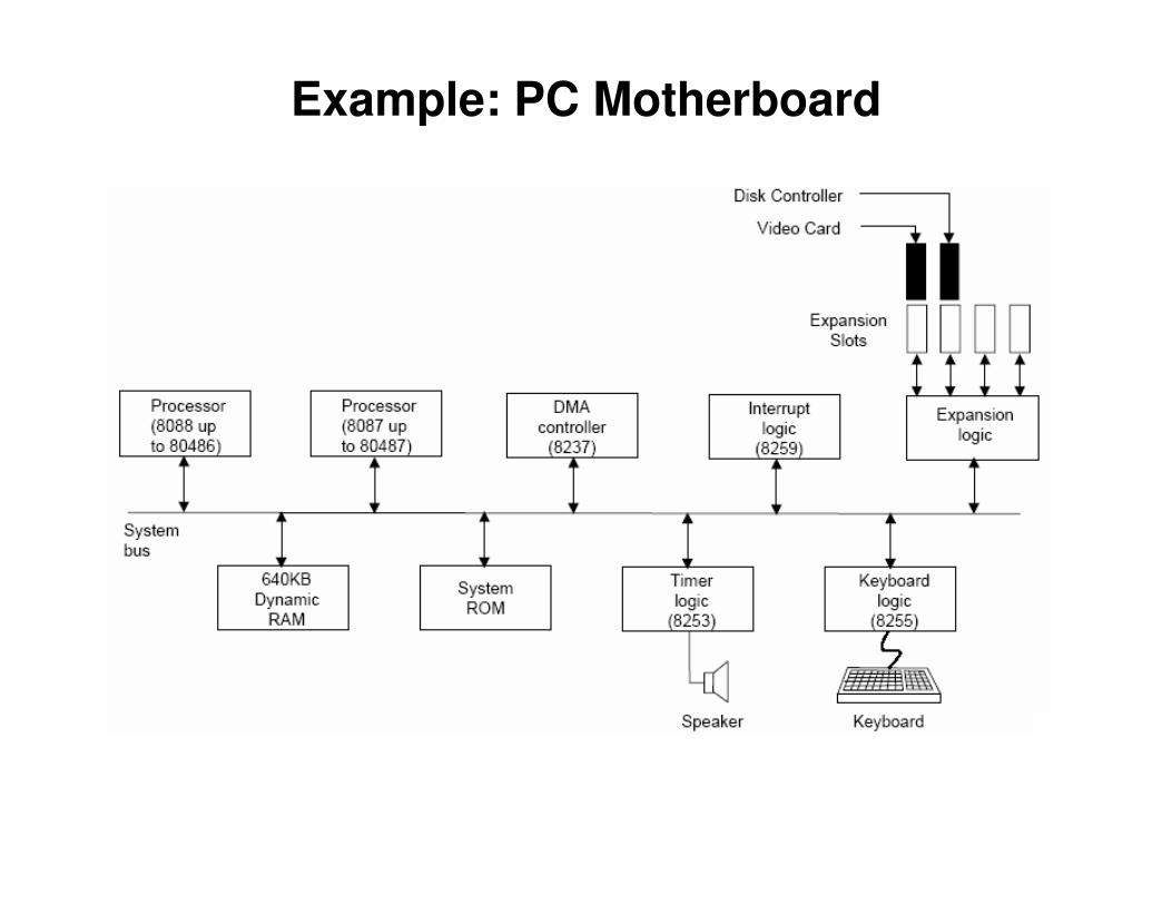
Example: PC Motherboard
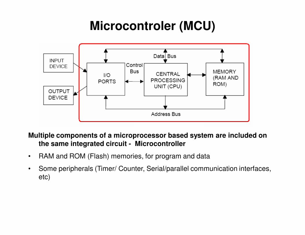
Microcontroler (MCU)
Multiple components of a microprocessor based system are included on
the same integrated circuit - Microcontroller
• RAM and ROM (Flash) memories, for program and data
• Some peripherals (Timer/ Counter, Serial/parallel communication interfaces,
etc)

Design with Microprocessors
General objective: using the microprocessors (microcontrollers) to develop
electronic systems for solving specific problems.
Example applications: autonomous robots, intelligent sensors, mobile sensors,
audio or video signal processing, automatic control of processes, etc.
Steps towards the goal:
• Study of the microcontroller’s capabilities and learning how to program it;
• Study of the microcontroller’s integrated resources, and the resources of the
microcontroller’s development board;
• Study of the external devices required for solving the specific problems;
• Study of the communication interfaces, data formats, and timing diagrams,
required for connecting the microcontroller to the external devices.

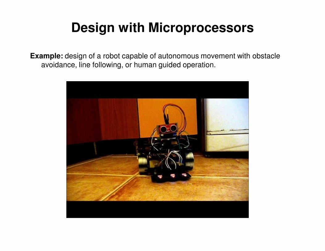
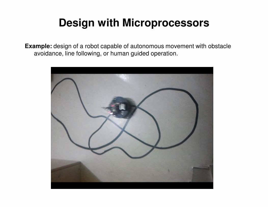
Design with Microprocessors
Example: design of a robot capable of autonomous movement with obstacle
avoidance, line following, or human guided operation.
Microcontroller: AVR ATMega328, Arduino board,
C/C++ programming
Internal resources: I/O ports, interrupts, serial
communication interface, PWM generator
External components: 1 DC motor, 1 servo motor,
reflectivity sensors, H bridge, sonar distance
sensor, Bluetooth module.
Communication interfaces: UART serial between
MCU and the Bluetooth module, PWM between
MCU and the motors, analog signal from the
reflectivity sensors, digital pulse between sonar
and MCU.
Algorithms: scanning the environment for obstacle
detection, line following, wheel control for straight
line movement, etc.
Design with Microprocessors
Example: design of a robot capable of autonomous movement with obstacle
avoidance, line following, or human guided operation.
Design with Microprocessors
Example: design of a robot capable of autonomous movement with obstacle
avoidance, line following, or human guided operation.
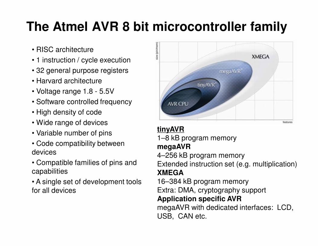
The Atmel AVR 8 bit microcontroller family
• RISC architecture
• 1 instruction / cycle execution
• 32 general purpose registers
• Harvard architecture
• Voltage range 1.8 - 5.5V
• Software controlled frequency
• High density of code
• Wide range of devices
• Variable number of pins
• Code compatibility between
devices
• Compatible families of pins and
capabilities
• A single set of development tools
for all devices
tinyAVR1–8 kB program memory
megaAVR
4–256 kB program memory
Extended instruction set (e.g. multiplication)
XMEGA
16–384 kB program memory
Extra: DMA, cryptography support
Application specific AVRmegaAVR with dedicated interfaces: LCD,
USB, CAN etc.

Generic architecture of an AVR
microcontroller• RISC machine (Two address load-store)
• Modified Harvard architecture – special instructions allow reading data from
the program memory
• Two stage pipeline: Fetch & Execute
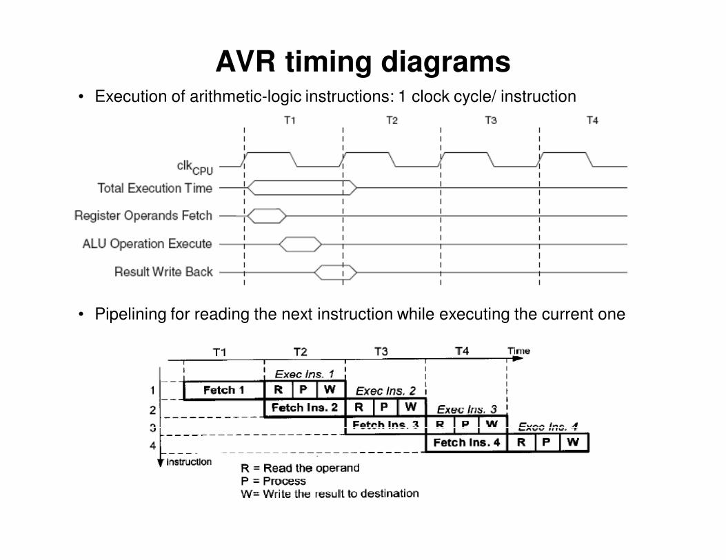
AVR timing diagrams• Execution of arithmetic-logic instructions: 1 clock cycle/ instruction
• Pipelining for reading the next instruction while executing the current one
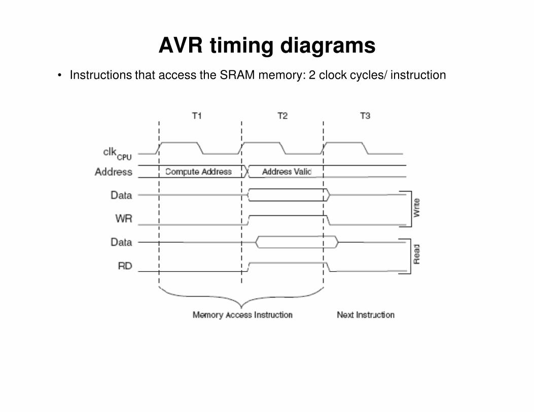
AVR timing diagrams
• Instructions that access the SRAM memory: 2 clock cycles/ instruction
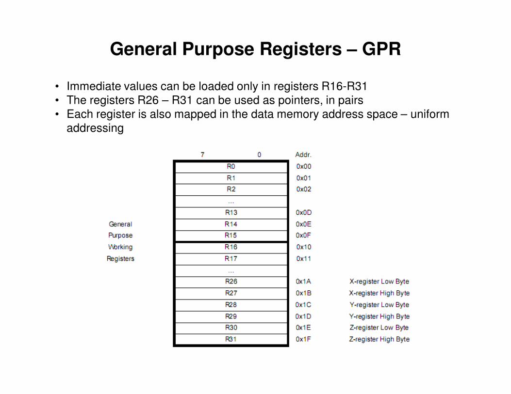
General Purpose Registers – GPR
• Immediate values can be loaded only in registers R16-R31
• The registers R26 – R31 can be used as pointers, in pairs
• Each register is also mapped in the data memory address space – uniform
addressing

Register operations
• Data copy
mov r4, r7
• Working with immediate values – possible only with r16 – r31
ldi r16, 5
ori r16, 0xF0
andi r16, 0x80
subi r20, 1
• Logic and arithmetic operations between registers
add r1, r2
or r3, r4
lsl r5
mul r5, r18 – r1:r0 = r5*r18
rol r7
ror r9inc r19dec r17
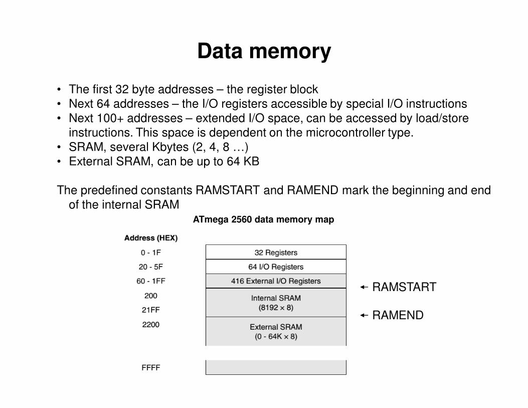
Data memory
• The first 32 byte addresses – the register block
• Next 64 addresses – the I/O registers accessible by special I/O instructions
• Next 100+ addresses – extended I/O space, can be accessed by load/store
instructions. This space is dependent on the microcontroller type.
• SRAM, several Kbytes (2, 4, 8 …)
• External SRAM, can be up to 64 KB
The predefined constants RAMSTART and RAMEND mark the beginning and end
of the internal SRAM
RAMEND
ATmega 2560 data memory map
RAMSTART

Data memory operations
• Direct addressing
lds r3, 0x10FE
lsl r3
sts 0x10FE, r3
• Indirect addressing, using the pointer registers X, Y, Z
ldi r27, 0x10 The High byte of X is r27
ldi r26, 0xFE The Low byte of X is r26
ld r0, X
lsl r0
st X, r0
• Auto-increment/decrement indirect addressing
ld r0, X+ access location pointed by X, then increment X
ld r0, +X increment X, then access location pointed by X
ld r0, X-ld r0, -X
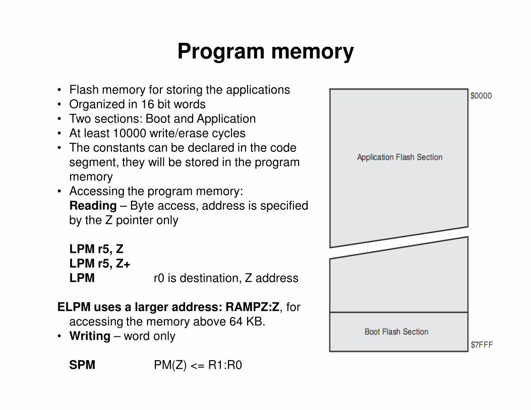
Program memory
• Flash memory for storing the applications
• Organized in 16 bit words
• Two sections: Boot and Application
• At least 10000 write/erase cycles
• The constants can be declared in the code
segment, they will be stored in the program
memory
• Accessing the program memory:
Reading – Byte access, address is specified
by the Z pointer only
LPM r5, Z
LPM r5, Z+
LPM r0 is destination, Z address
ELPM uses a larger address: RAMPZ:Z, for
accessing the memory above 64 KB.
• Writing – word only
SPM PM(Z) <= R1:R0
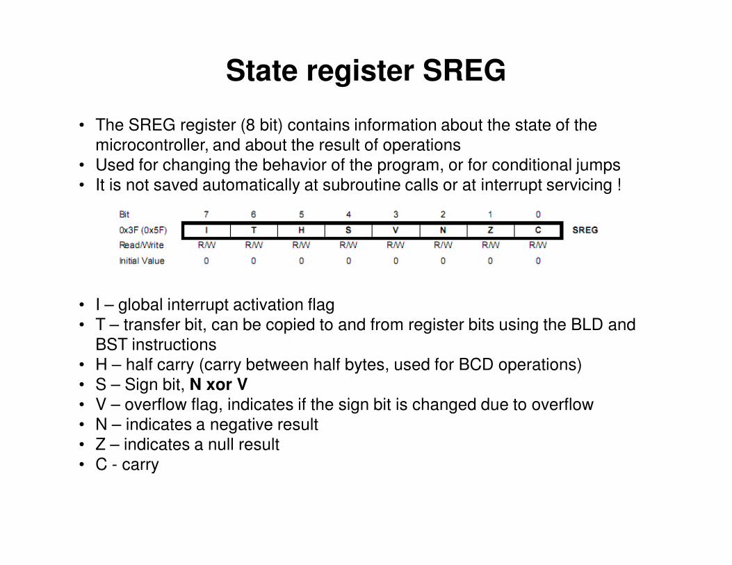
State register SREG
• The SREG register (8 bit) contains information about the state of the
microcontroller, and about the result of operations
• Used for changing the behavior of the program, or for conditional jumps
• It is not saved automatically at subroutine calls or at interrupt servicing !
• I – global interrupt activation flag
• T – transfer bit, can be copied to and from register bits using the BLD and
BST instructions
• H – half carry (carry between half bytes, used for BCD operations)
• S – Sign bit, N xor V
• V – overflow flag, indicates if the sign bit is changed due to overflow
• N – indicates a negative result
• Z – indicates a null result
• C - carry
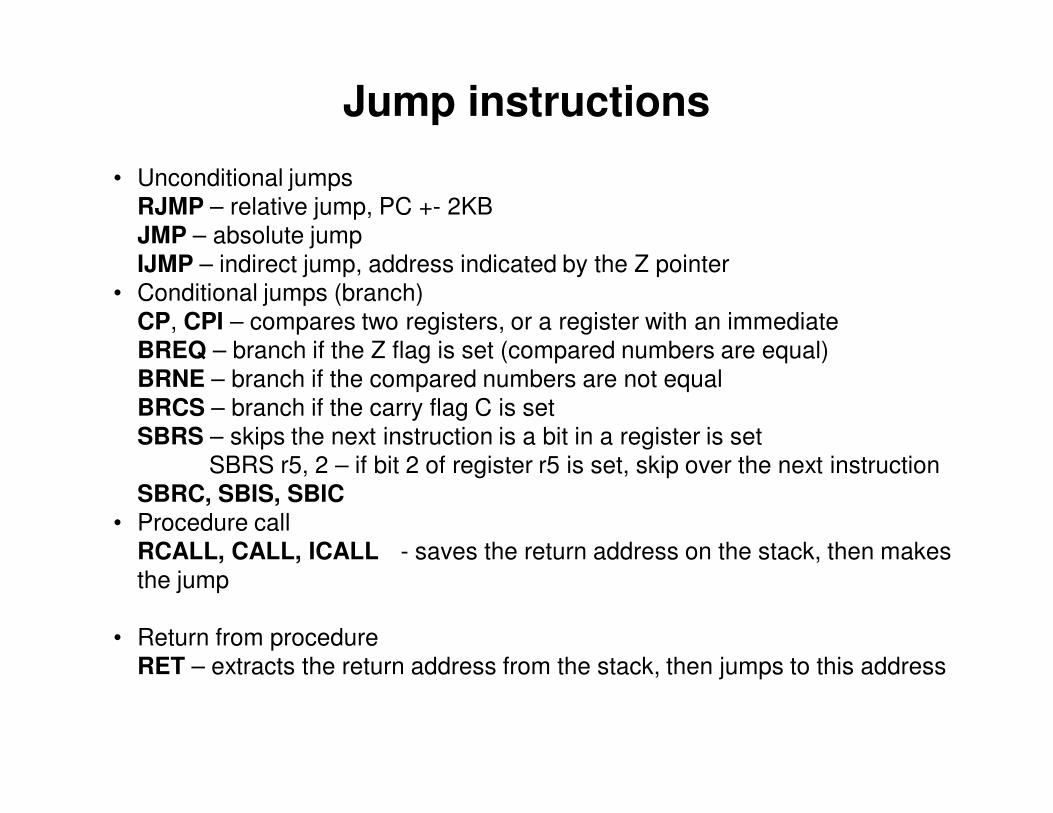
Jump instructions
• Unconditional jumps
RJMP – relative jump, PC +- 2KB
JMP – absolute jump
IJMP – indirect jump, address indicated by the Z pointer
• Conditional jumps (branch)
CP, CPI – compares two registers, or a register with an immediate
BREQ – branch if the Z flag is set (compared numbers are equal)
BRNE – branch if the compared numbers are not equal
BRCS – branch if the carry flag C is set
SBRS – skips the next instruction is a bit in a register is set
SBRS r5, 2 – if bit 2 of register r5 is set, skip over the next instruction
SBRC, SBIS, SBIC
• Procedure call
RCALL, CALL, ICALL - saves the return address on the stack, then makes
the jump
• Return from procedure
RET – extracts the return address from the stack, then jumps to this address

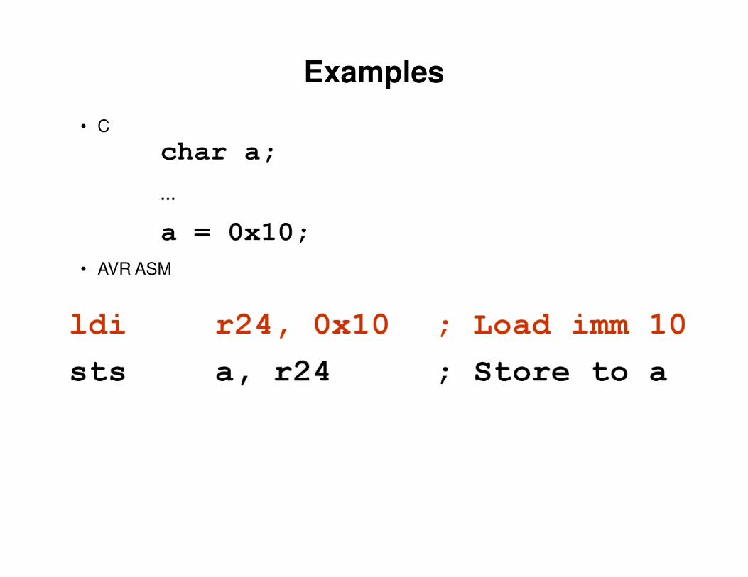
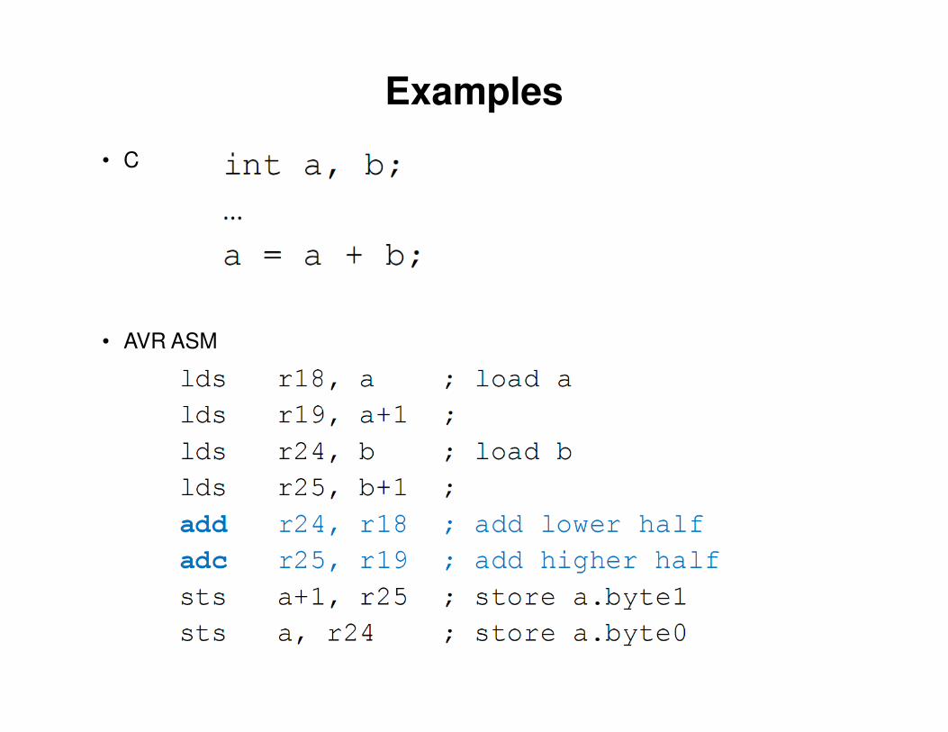
Examples
• C
• AVR ASM
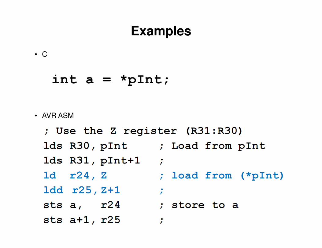
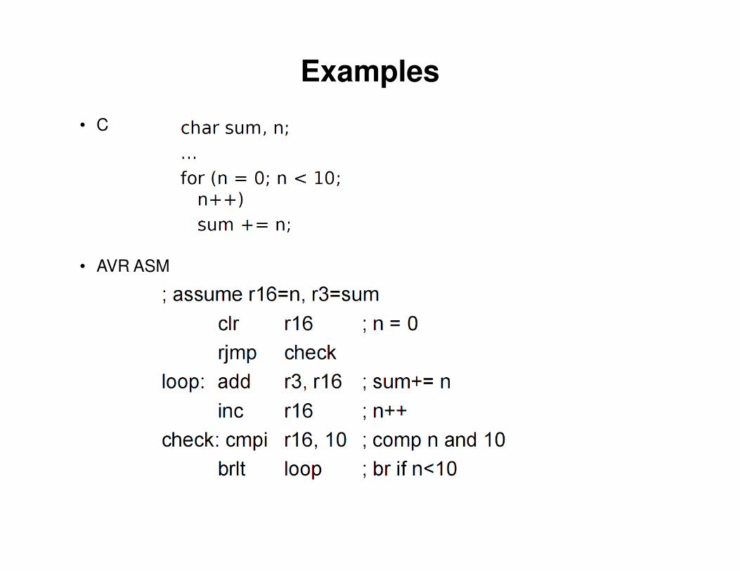
Examples
• C
• AVR ASM
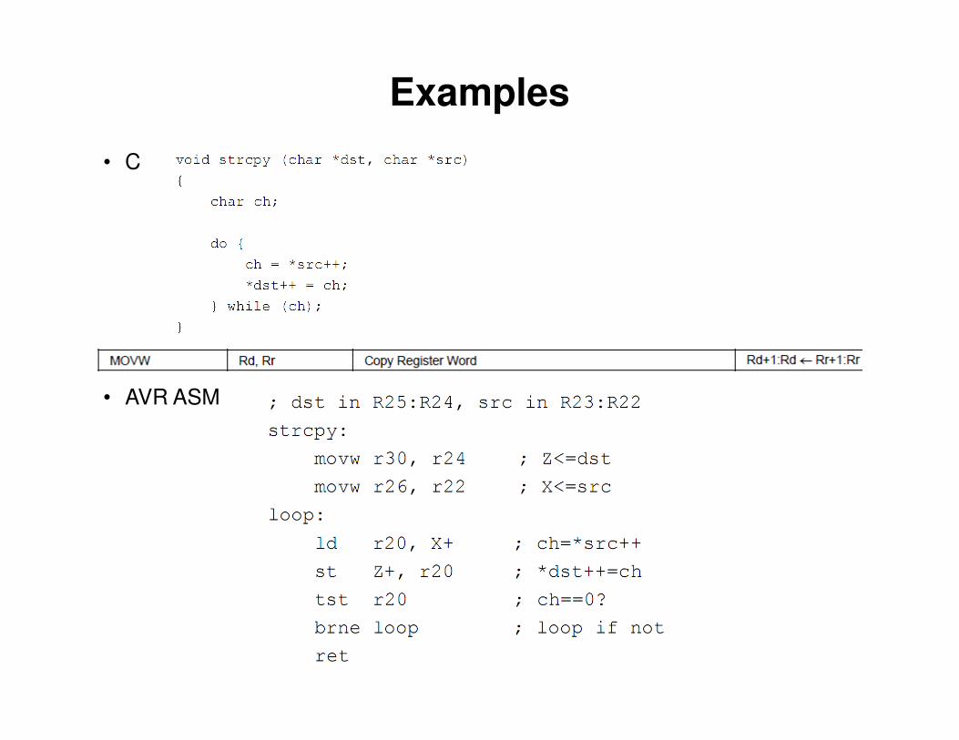
Examples
• C
• AVR ASM
Examples
• C
• AVR ASM
Examples
• C
• AVR ASM
Examples
• C
• AVR ASM

The AVR AtMega 2560 microcontroller
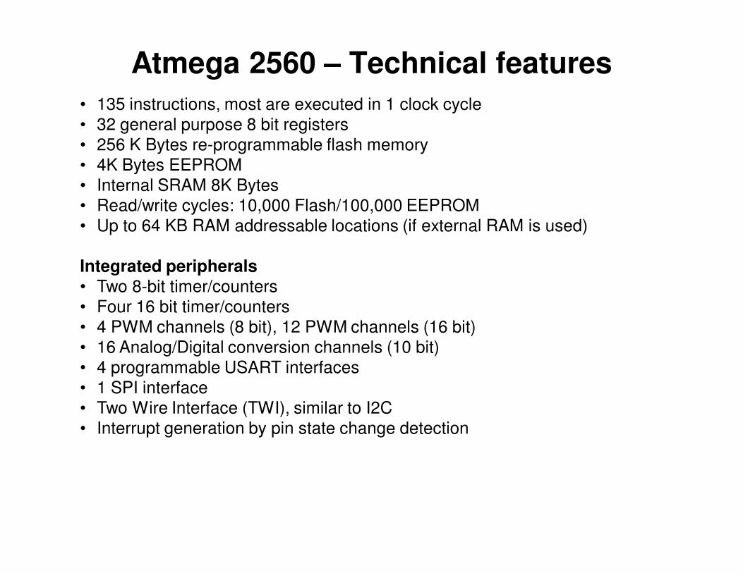
Atmega 2560 – Technical features
• 135 instructions, most are executed in 1 clock cycle
• 32 general purpose 8 bit registers
• 256 K Bytes re-programmable flash memory
• 4K Bytes EEPROM
• Internal SRAM 8K Bytes
• Read/write cycles: 10,000 Flash/100,000 EEPROM
• Up to 64 KB RAM addressable locations (if external RAM is used)
Integrated peripherals
• Two 8-bit timer/counters
• Four 16 bit timer/counters
• 4 PWM channels (8 bit), 12 PWM channels (16 bit)
• 16 Analog/Digital conversion channels (10 bit)
• 4 programmable USART interfaces
• 1 SPI interface
• Two Wire Interface (TWI), similar to I2C
• Interrupt generation by pin state change detection
Arduino
• Microcontroller boards and open source development tools
• Hides the microcontroller specific details, providing a unified API
• Wide range of boards, shields and accessories
• Vast quantity of documentation, most of it free
• Vast quantity of examples for most problems
Web: www.arduino.cc
Distributors in Romania:
www.robofun.ro – originals, more expensive
www.ardushop.ro – clones, cheaper
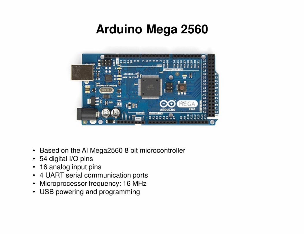
Arduino Mega 2560
• Based on the ATMega2560 8 bit microcontroller
• 54 digital I/O pins
• 16 analog input pins
• 4 UART serial communication ports
• Microprocessor frequency: 16 MHz
• USB powering and programming

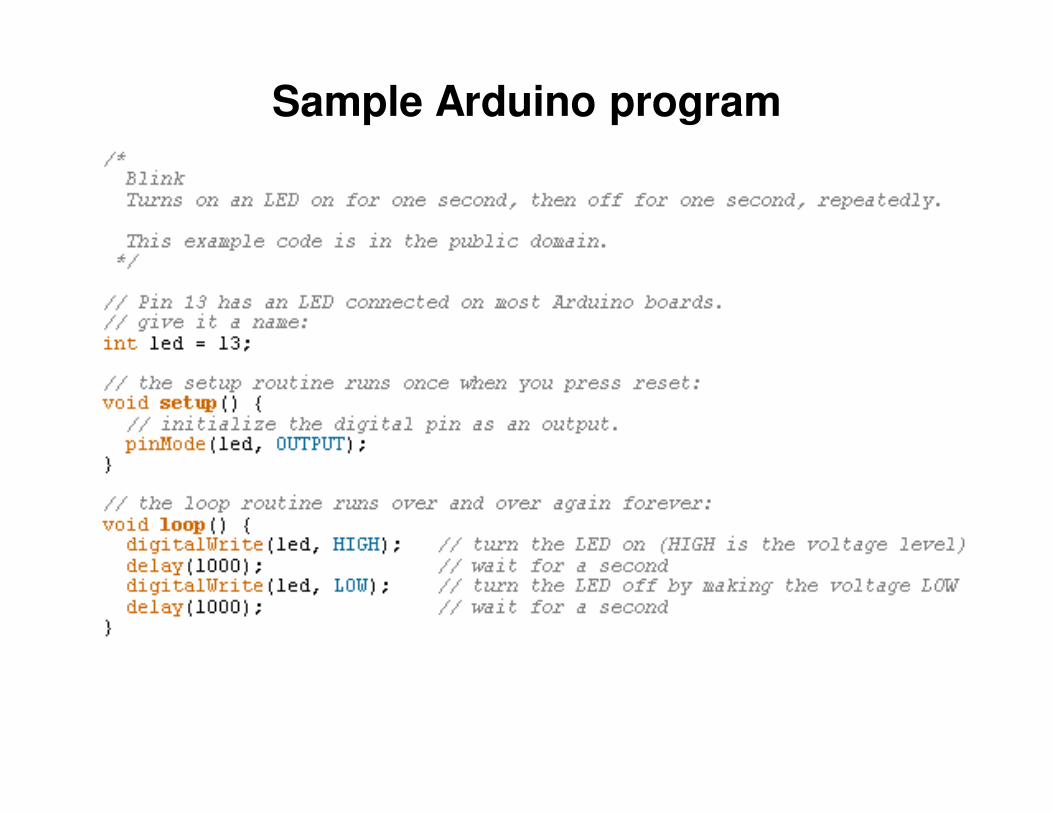
Sample Arduino program
• Intermittent lighting of a LED, connected to an output pin (digital output)
Sample Arduino program
Top Related