


Languages
Pages
Legal


S T R O N G E R T H A N S T E E LSM.
COLD-FORMED STRUCTURAL FRAMING PRODUCTS technical design guide
M E M B E R P R O P E R T I E S & S PA N S • C U R TA I N WA L L S • L O A D-B E A R I N G WA L L S • J O I S T S • F R A M I N G D E TA I L S
IN CONFORMANCE WITH: AISI S100-12 North American Specification [NASPEC] • International Building Code [IBC] 2015
COLD-FORMED STRUCTURAL FRAMING PRODUCTS technical design guide2017

T H E F U T U R E O F S T E E L F R A M I N G
T A K E S F O R M Clark Dietrich
S T R U C T U R A L S T E E L F R A M I N G S Y S T E M S
1
Product information 3
General notes 4
Physical & structural properties 5-16O ver v iew 5 - 6S t ud / Tr ack pr oper t ies 7-16
Stud shear & track shear 17A llowable s t ud shear 1 7A llowable t r ack shear 1 7
Allowable wall heights 18-38In t er ior wall heigh t s 19 -25E x t er ior cur t ain wall over v iew 2 6Cur t ain wall heigh t s 2 7- 38
Allowable axial & lateral loads 39-58O ver v iew 4 0A llowable combined a x ial & la t er al loads 4 1 - 5 4A llowable unbr aced a x ial loads 55 - 59
Floor joist framing 66-96O ver v iew 6 7Floor jois t span t ables 68 - 9 1
Allowable web crippling loads 92-95O ver v iew 9 3A llowable web cr ippling loads —single member s 9 4A llowable web cr ippling loads —buil t- up member s 95
Reference 96-103Fas t ening op t ions 9 7Ty pical cons t r uc t ion de t ails 98 -10 1Suppor t t ools 10 2L E E D ® in f or ma t ion and r equir emen t s 10 3Ma t er ial cer t i f ica t ion 10 4Manu f ac t ur ing and sales loca t ions 10 4
While this document is quite comprehensive, it does not completely cover our vast and growing lineup of products. You will find more complete information on each member selection, as well as nonstandard products, at clarkdietrich.com.
Need Product Submittals? Use SubmittalPro® at clarkdietrich.com.
Need help with product selection, ordering, scheduling, delivery, or anything else?
Call us at 800-543-7140, or on the West Coast at 800-365-5284.
and the applications are many. But when you add in the product scope, design innovations and technical expertise that a company like ClarkDietrich alone can provide, the opportunities before you take on an entirely new dimension.
Due to our long history and core competency in steel framing, we can provide an unparalleled level of in-depth knowledge—not only to help you meet the codes, but to surpass expectations for cost-effective, high-performance solutions in today’s commercial and residential buildings.
This publication is specifically designed to help you as a contractor, engineer or architect find the right steel framing components for your projects. What’s more, we’ve worked to make this the industry’s most comprehensive technical support document for cold-formed steel framing.
It’s exactly the kind of resource you’d expect from a partner like ClarkDietrich. Yes, we’re known as a manufacturer of extensively tested, code-compliant steel framing products. But we also offer products that perform as a system, we support a range of efforts for smarter installation and design, and we provide the expertise of a versatile engineering services team—and all on a nationwide scale.
In the following pages, you will find ample information, data and notes to reliably guide your decisions. But please feel free to contact us at any time for additional clarity or support.
The properties of cold-formed steel are impressive,
TABLE OF CONTENTS
T A B L E O F C O N T E N T S2
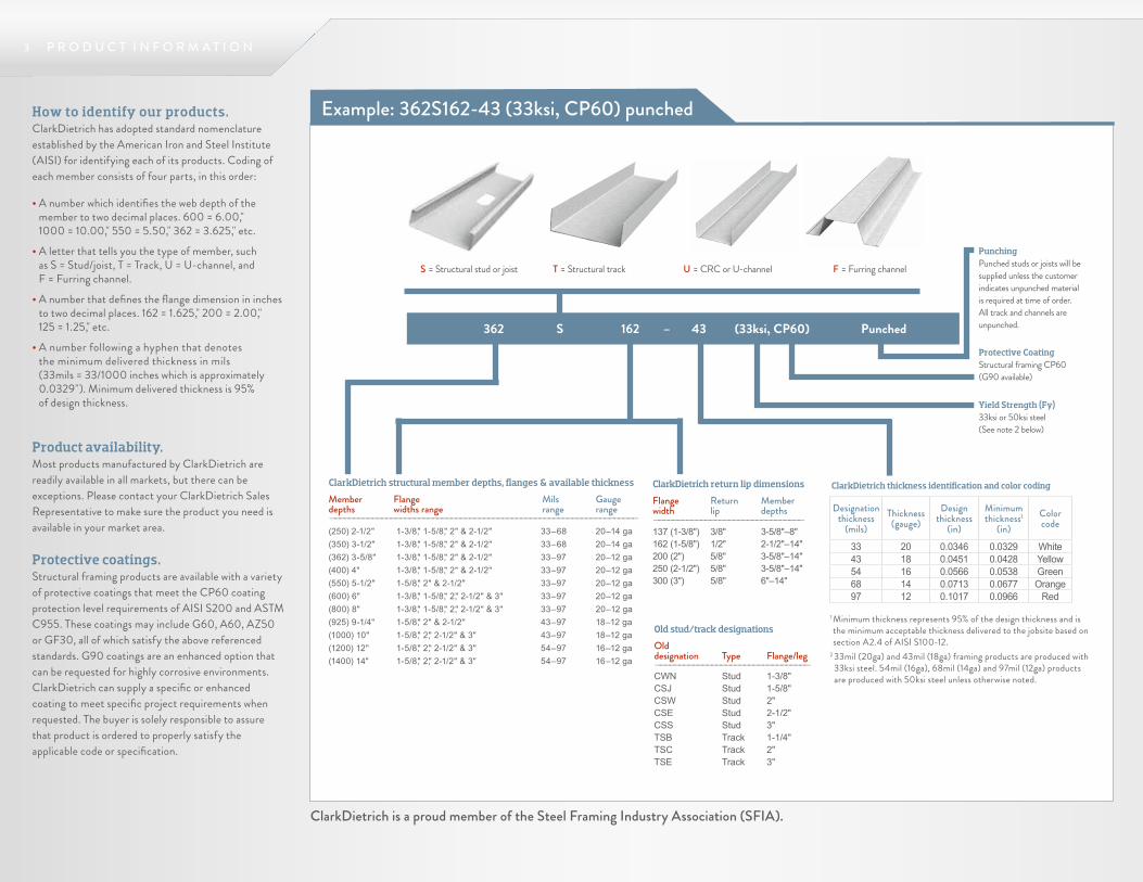
How to identify our products.ClarkDietrich has adopted standard nomenclature established by the American Iron and Steel Institute (AISI) for identifying each of its products. Coding of each member consists of four parts, in this order:
• A number which identifies the web depth of the member to two decimal places. 600 = 6.00," 1000 = 10.00," 550 = 5.50," 362 = 3.625," etc.
• A letter that tells you the type of member, such as S = Stud/joist, T = Track, U = U-channel, and F = Furring channel.
• A number that defines the flange dimension in inches to two decimal places. 162 = 1.625," 200 = 2.00," 125 = 1.25," etc.
• A number following a hyphen that denotes the minimum delivered thickness in mils (33mils = 33/1000 inches which is approximately 0.0329"). Minimum delivered thickness is 95% of design thickness.
362 S 162 – 43 (33ksi, CP60) PunchedProtective CoatingStructural framing CP60 (G90 available)
PunchingPunched studs or joists will be supplied unless the customer indicates unpunched material is required at time of order. All track and channels are unpunched.
S = Structural stud or joist T = Structural track U = CRC or U-channel F = Furring channel
Product availability.Most products manufactured by ClarkDietrich are readily available in all markets, but there can be exceptions. Please contact your ClarkDietrich Sales Representative to make sure the product you need is available in your market area.
Protective coatings.Structural framing products are available with a variety of protective coatings that meet the CP60 coating protection level requirements of AISI S200 and ASTM C955. These coatings may include G60, A60, AZ50 or GF30, all of which satisfy the above referenced standards. G90 coatings are an enhanced option that can be requested for highly corrosive environments. ClarkDietrich can supply a specific or enhanced coating to meet specific project requirements when requested. The buyer is solely responsible to assure that product is ordered to properly satisfy the applicable code or specification.
P R O D U C T I N F O R M A T I O N3
Example: 362S162-43 (33ksi, CP60) punched
ClarkDietrich thickness identification and color codingClarkDietrich structural member depths, flanges & available thickness
Member Flange Mils Gaugedepths widths range range range——————————————————————————————————————————————————————————————————(250) 2-1/2" 1-3/8," 1-5/8," 2" & 2-1/2" 33–68 20–14 ga(350) 3-1/2" 1-3/8," 1-5/8," 2" & 2-1/2" 33–68 20–14 ga(362) 3-5/8" 1-3/8," 1-5/8," 2" & 2-1/2" 33–97 20–12 ga(400) 4" 1-3/8," 1-5/8," 2" & 2-1/2" 33–97 20–12 ga(550) 5-1/2" 1-5/8," 2" & 2-1/2" 33–97 20–12 ga(600) 6" 1-3/8," 1-5/8," 2," 2-1/2" & 3" 33–97 20–12 ga(800) 8" 1-3/8," 1-5/8," 2," 2-1/2" & 3" 33–97 20–12 ga(925) 9-1/4" 1-5/8," 2" & 2-1/2" 43–97 18–12 ga(1000) 10" 1-5/8," 2," 2-1/2" & 3" 43–97 18–12 ga(1200) 12" 1-5/8," 2," 2-1/2" & 3" 54–97 16–12 ga(1400) 14" 1-5/8," 2," 2-1/2" & 3" 54–97 16–12 ga
Old stud/track designations
Old designation Type Flange/leg—————————————————————————————————CWN Stud 1-3/8"CSJ Stud 1-5/8"CSW Stud 2"CSE Stud 2-1/2"CSS Stud 3"TSB Track 1-1/4"TSC Track 2"TSE Track 3"
2-1/2" widestuds 3-5/8" andwider
3/4" 1-1/2"
4"
2"
C-Stud
FlangeWeb
Lip/return
ClarkDietrich is a proud member of the Steel Framing Industry Association (SFIA).
1 Minimum thickness represents 95% of the design thickness and is the minimum acceptable thickness delivered to the jobsite based on section A2.4 of AISI S100-12.
2 33mil (20ga) and 43mil (18ga) framing products are produced with 33ksi steel. 54mil (16ga), 68mil (14ga) and 97mil (12ga) products are produced with 50ksi steel unless otherwise noted.
Designation thickness
(mils)Thickness
(gauge)Design
thickness (in)
Minimum thickness1
(in)Color code
33 20 0.0346 0.0329 White43 18 0.0451 0.0428 Yellow54 16 0.0566 0.0538 Green68 14 0.0713 0.0677 Orange97 12 0.1017 0.0966 Red
ClarkDietrich return lip dimensions
Flange Return Member width lip depths————————————————————————————————137 (1-3/8") 3/8" 3-5/8"–8"162 (1-5/8") 1/2" 2-1/2"–14"200 (2") 5/8" 3-5/8"–14"250 (2-1/2") 5/8" 3-5/8"–14"300 (3") 5/8" 6"–14"
Yield Strength (Fy)33ksi or 50ksi steel (See note 2 below)
Support tools Catalog notes
Technical Service.Technical Service is the most important way we serve our present and prospective customers. After all, your experience with our products will only be a good one if you are satisfied that the material is right for the job and that it is being installed correctly. That’s why we have provided four ways to make sure you can get the Technical Service you need.
Web support—www.clarkdietrich.com contains information on the company, its products and a wealth of other information related to the steel framing industry. This website also provides you with more detailed information about all of the company’s products, including load and limiting heights tables for member sizes and configurations not contained in this printed manual. Please visit this site to familiarize yourself with what we have to offer.
Engineering software—To make sure you design structures successfully, we provide engineering software FREE to customers, engineers, architects and students. This state-of-the-art and user-friendly software helps configure exterior curtain wall framing for wind loads, load-bearing framing for combined loads, joists for required spans and anticipated load configurations, etc. A download is available from our website.
ClarkDietrich Engineering Services—A full-service design and engineering firm that provides certified engineering shop drawing packages. ClarkDietrich Engineering Services is licensed throughout the United States and can be reached by calling 877-832-3206.
ClarkDietrich Technical Services—For general technical service on products, member sizing, industry standards, framing details or information on engineering software, please call technical services at 888-437-3244.
Architectural specification review.Over time, project specifications can become outdated. For suggestions on how to improve the performance of your specifications, contact us about a complimentary review at 330-974-0835.
G E N E R A L N O T E S4
Standards and specifications.All members comply with ASTM standards shown in the Material Certification at the back of this catalog. All structural properties are developed in accordance with the American Iron and Steel Institute’s “Specification for the Design of Cold-Formed Steel Structural Members, S100-12.”
General notes.The data contained in this catalog is intended to be used as a general guideline only and does not replace the judgment and designs of a qualified architect and/or engineer.
Product, application renderings and photographs are provided as a tool to show the general intent of the framing or finishing application only. These renderings or photographs may or may not be applicable to a specific project. They do not replace or supercede the architect or engineer of record, ASTM guidelines, U.S. national or local building codes, or approved industry standards.
ClarkDietrich reserves the right to change or modify the information contained in this catalog without prior notice or obligation. The information in this catalog supercedes all previously published data. Products and systems may be improved and/or changed after this catalog is printed.
All products described here may not be available in all geographic markets. Consult your local sales office for information.
Warranty. ClarkDietrich warrants that all products are free from defect at time of shipment, and are manufactured in accordance with company and/or industry standards as applicable.
NOTICE: ClarkDietrich shall not be liable for incidental and consequential damages, directly or indirectly sustained, nor for any loss caused by application of these goods not in accordance with current printed instructions or for other than the intended use. Our liability is expressly limited to replacement of defective goods. Any claim shall be deemed waived unless made in writing to us within thirty (30) days from date it was or reasonably should have been discovered.
5 P H Y S I C A L & S T R U C T U R A L P R O P E R T I E S
clarkdietrich.comPub. No. CD-STR-TechGuide 6/17 The technical content of this literature is effective 6/1/17 and supersedes all previous information.Complies with AISI S100-12 • IBC 2015
Overview
Steel framing is engineered to take advantage of the physical properties of formed steel to provide strength where needed and as needed in the construction of buildings. This section provides the basic information needed by architects and engineers to make sure the member called for in the plans will meet the criteria required by the structure.
Structural framing general notes.1 Physical properties have been calculated in conformance with AISI
S100-12.2 Effective properties of structural framing incorporate the strength
increase from the cold work of forming as applicable per NASPEC Section A7.2.
3 Gross properties are based on the cross-section away from web punchouts. Effective properties are based on knockout/punched sections.
4 The effective moment of inertia for deflection is calculated at a stress which results in a section modulus, such that the stress times the section modulus at that stress is equal to the allowable moment. AISI S100-12 Procedure 1 for serviceability determination has been used.
LEED® Services BUILD GREEN with ClarkDietrich Building Systems ClarkDietrich Building Systems is an active member of the U.S. Green Building Council and is committed to supplying quality products that are environmentally responsible. We are continually working to develop greener building products and sustainable business practices. ClarkDietrich steel framing helps contribute points toward LEED® certification. For more details contact Technical Services at 888-437-3244 or visit www.clarkdietrich.com/LEED.
Symbols and terms.The following tables are provided to help architects and engineers design structures that withstand various forces. Those forces include vertical loads such as weight from overhead, lateral loads such as wind, other applied pressure or a combination of those. Such natural forces can result in deflection and/or twisting of cold-formed steel framing members.
Key among these tables are the physical and structural properties tables in this next section. The tables provide typical data required to make determinations about the suitability of materials for certain intended purposes. The data is identified by commonly used engineering symbols and terms. This legend will help you to understand the symbols and terms used here. Ix = (in4): Moment of inertia about the X-X axis, used for DEFLECTION Sx = (in3): Section modulus about the X-X axis, used for STRESS & LOADS Rx = (in): Radius of gyration about the X-X axis Iy = (in4): Moment of inertia about the Y-Y axis Ry = (in): Radius of gyration about the Y-Y axis, used for AXIAL LOADS
Wind load (lbs/sq ft): Forces produced by wind, either direct wind (positive pressure), a vacuum (negative pressure) or those generated by wind whipping around the corners of a building. These forces are usually calculated according to the prevailing building code. Wind forces are referred to as transverse loads, are perpendicular to the wall, and cause the wall to deflect.
Axial load (lbs): A vertical force produced by overhead loads, such as floors and roof. Floors and roofs contain both dead loads and live loads, which combine to make up the vertical loading.
Header: A joist or beam that spans two or more studs, accepts overhead loads from floors and roof and distributes the overhead load to the jamb studs supporting the header.
Deflection: The amount of movement of a system, usually greatest at the midpoint, caused by transverse loading. L/120: Length (height) of stud, in inches, divided by 120 (short interior wall studs) L/240: Length (height) of stud, in inches, divided by 240 (interior wall studs, exterior siding or EIFS) L/360: Length (height) of stud, in inches, divided by 360 (exterior stucco) L/600: Length (height) of stud, in inches, divided by 600 (exterior brick) L/720: Length (height) of stud, in inches, divided by 720 (exterior brick)
Limited deflection: A design criteria which specifies the maximum allowable deflection for a system (L/240, L/360, L/600, etc.).
General table notes.Unless otherwise noted, properties are computed according to the AISI S100-12.
Sxe and Mxa for studs are based on the perforated web properties for the standard ClarkDietrich oval knockout. For tracks, Sxe and Mxa are based on a solid section. Ixe is based on the solid section value for both studs and track.
Overview
6 P H Y S I C A L & S T R U C T U R A L P R O P E R T I E S
clarkdietrich.comThe technical content of this literature is effective 6/1/17 and supersedes all previous information.Pub. No. CD-STR-TechGuide 6/17Complies with AISI S100-12 • IBC 2015
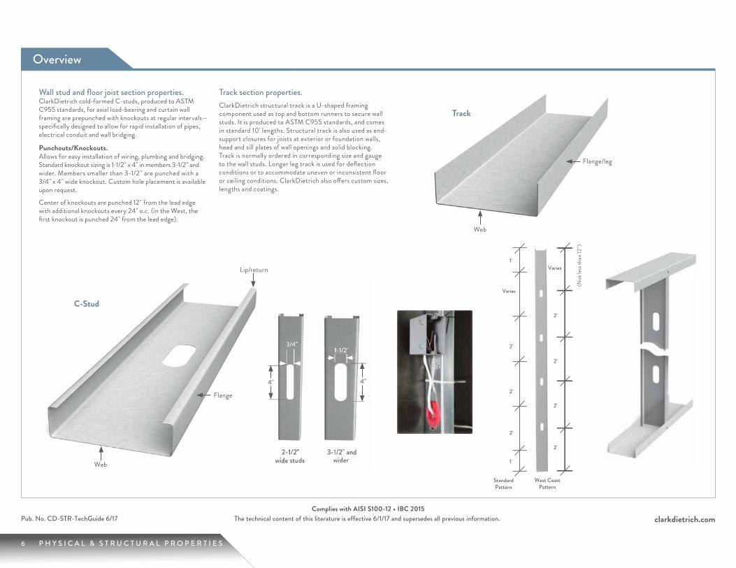
Wall stud and floor joist section properties.ClarkDietrich cold-formed C-studs, produced to ASTM C955 standards, for axial load-bearing and curtain wall framing are prepunched with knockouts at regular intervals—specifically designed to allow for rapid installation of pipes, electrical conduit and wall bridging.
Punchouts/Knockouts.Allows for easy installation of wiring, plumbing and bridging. Standard knockout sizing is 1-1/2" x 4" in members 3-1/2" and wider. Members smaller than 3-1/2" are punched with a 3/4" x 4" wide knockout. Custom hole placement is available upon request.
Center of knockouts are punched 12" from the lead edge with additional knockouts every 24" o.c. (in the West, the first knockout is punched 24" from the lead edge).
Track section properties.ClarkDietrich structural track is a U-shaped framing component used as top and bottom runners to secure wall studs. It is produced to ASTM C955 standards, and comes in standard 10' lengths. Structural track is also used as end-support closures for joists at exterior or foundation walls, head and sill plates of wall openings and solid blocking. Track is normally ordered in corresponding size and gauge to the wall studs. Longer leg track is used for deflection conditions or to accommodate uneven or inconsistent floor or ceiling conditions. ClarkDietrich also offers custom sizes, lengths and coatings.
Track
C-Stud
Web
Web
Flange/leg
Lip/return
Flange
(Not
less
than
12")
7 P H Y S I C A L & S T R U C T U R A L P R O P E R T I E S
2 - 1 / 2 " S T U D / T R A C K P R O P E R T I E S
clarkdietrich.comPub. No. CD-STR-TechGuide 6/17 The technical content of this literature is effective 6/1/17 and supersedes all previous information.Complies with AISI S100-12 • IBC 2015
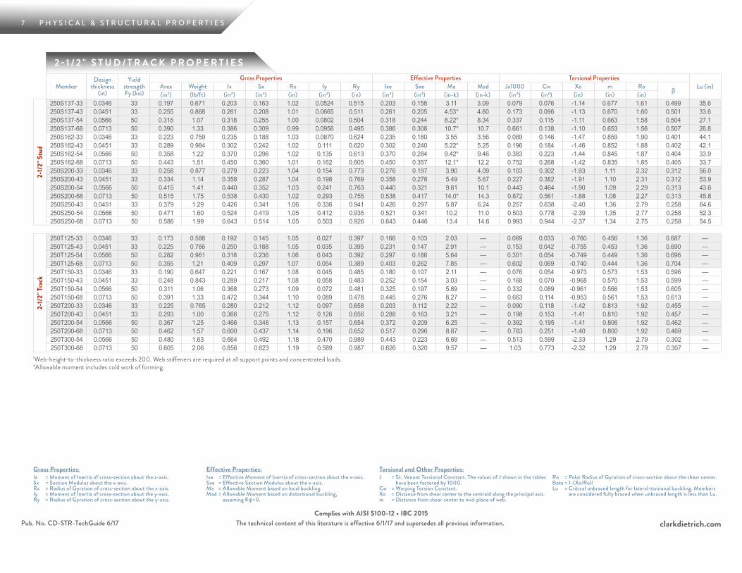
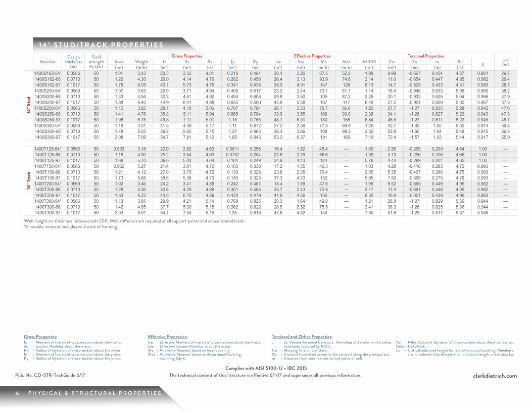
Gross Properties:Ix = Moment of Inertia of cross-section about the x-axis.Sx = Section Modulus about the x-axis.Rx = Radius of Gyration of cross-section about the x-axis.Iy = Moment of Inertia of cross-section about the y-axis.Ry = Radius of Gyration of cross-section about the y-axis.
Effective Properties:Ixe = Effective Moment of Inertia of cross-section about the x-axis.Sxe = Effective Section Modulus about the x-axis.Ma = Allowable Moment based on local buckling.Mad = Allowable Moment based on distortional buckling,
assuming Kφ=0.
Torsional and Other Properties:J = St. Venant Torsional Constant. The values of J shown in the tables
have been factored by 1000.Cw = Warping Torsion Constant.Xo = Distance from shear center to the centroid along the principal axis.m = Distance from shear center to mid-plane of web.
Ro = Polar Radius of Gyration of cross-section about the shear center.Βeta = 1-(Xo/Ro).2Lu = Critical unbraced length for lateral-torsional buckling. Members
are considered fully braced when unbraced length is less than Lu.
1Web-height-to-thickness ratio exceeds 200. Web stiffeners are required at all support points and concentrated loads. *Allowable moment includes cold work of forming.
MemberDesign
thickness (in)
Yield strength Fy (ksi)
Gross Properties Effective Properties Torsional PropertiesLu (in)Area Weight Ix Sx Rx Iy Ry Ixe Sxe Ma Mad Jx1000 Cw Xo m Ro β(in2) (lb/ft) (in4) (in3) (in) (in4) (in) (in4) (in3) (in-k) (in-k) (in4) (in6) (in) (in) (in)
2-1/
2" S
tud
250S137-33 0.0346 33 0.197 0.671 0.203 0.163 1.02 0.0524 0.515 0.203 0.158 3.11 3.09 0.079 0.076 -1.14 0.677 1.61 0.499 35.6250S137-43 0.0451 33 0.255 0.868 0.261 0.208 1.01 0.0665 0.511 0.261 0.205 4.53* 4.60 0.173 0.096 -1.13 0.670 1.60 0.501 33.6250S137-54 0.0566 50 0.316 1.07 0.318 0.255 1.00 0.0802 0.504 0.318 0.244 8.22* 8.34 0.337 0.115 -1.11 0.663 1.58 0.504 27.1250S137-68 0.0713 50 0.390 1.33 0.386 0.309 0.99 0.0956 0.495 0.386 0.308 10.7* 10.7 0.661 0.138 -1.10 0.653 1.56 0.507 26.8250S162-33 0.0346 33 0.223 0.759 0.235 0.188 1.03 0.0870 0.624 0.235 0.180 3.55 3.56 0.089 0.146 -1.47 0.859 1.90 0.401 44.1250S162-43 0.0451 33 0.289 0.984 0.302 0.242 1.02 0.111 0.620 0.302 0.240 5.22* 5.25 0.196 0.184 -1.46 0.852 1.88 0.402 42.1250S162-54 0.0566 50 0.358 1.22 0.370 0.296 1.02 0.135 0.613 0.370 0.284 9.42* 9.46 0.383 0.223 -1.44 0.845 1.87 0.404 33.9250S162-68 0.0713 50 0.443 1.51 0.450 0.360 1.01 0.162 0.605 0.450 0.357 12.1* 12.2 0.752 0.268 -1.42 0.835 1.85 0.405 33.7250S200-33 0.0346 33 0.258 0.877 0.279 0.223 1.04 0.154 0.773 0.276 0.197 3.90 4.09 0.103 0.302 -1.93 1.11 2.32 0.312 56.0250S200-43 0.0451 33 0.334 1.14 0.358 0.287 1.04 0.198 0.769 0.358 0.278 5.49 5.67 0.227 0.382 -1.91 1.10 2.31 0.312 53.9250S200-54 0.0566 50 0.415 1.41 0.440 0.352 1.03 0.241 0.763 0.440 0.321 9.61 10.1 0.443 0.464 -1.90 1.09 2.29 0.313 43.6250S200-68 0.0713 50 0.515 1.75 0.538 0.430 1.02 0.293 0.755 0.538 0.417 14.0* 14.3 0.872 0.561 -1.88 1.08 2.27 0.313 45.8250S250-43 0.0451 33 0.379 1.29 0.426 0.341 1.06 0.336 0.941 0.426 0.297 5.87 6.24 0.257 0.638 -2.40 1.36 2.79 0.258 64.6250S250-54 0.0566 50 0.471 1.60 0.524 0.419 1.05 0.412 0.935 0.521 0.341 10.2 11.0 0.503 0.778 -2.39 1.35 2.77 0.258 52.3250S250-68 0.0713 50 0.586 1.99 0.643 0.514 1.05 0.503 0.926 0.643 0.446 13.4 14.6 0.993 0.944 -2.37 1.34 2.75 0.258 54.5
2-1/
2" Tr
ack
250T125-33 0.0346 33 0.173 0.588 0.192 0.145 1.05 0.027 0.397 0.166 0.103 2.03 — 0.069 0.033 -0.760 0.456 1.36 0.687 —250T125-43 0.0451 33 0.225 0.766 0.250 0.188 1.05 0.035 0.395 0.231 0.147 2.91 — 0.153 0.042 -0.755 0.453 1.36 0.690 —250T125-54 0.0566 50 0.282 0.961 0.318 0.236 1.06 0.043 0.392 0.297 0.188 5.64 — 0.301 0.054 -0.749 0.449 1.36 0.696 —250T125-68 0.0713 50 0.355 1.21 0.409 0.297 1.07 0.054 0.389 0.403 0.262 7.85 — 0.602 0.069 -0.740 0.444 1.36 0.704 —250T150-33 0.0346 33 0.190 0.647 0.221 0.167 1.08 0.045 0.485 0.180 0.107 2.11 — 0.076 0.054 -0.973 0.573 1.53 0.596 —250T150-43 0.0451 33 0.248 0.843 0.289 0.217 1.08 0.058 0.483 0.252 0.154 3.03 — 0.168 0.070 -0.968 0.570 1.53 0.599 —250T150-54 0.0566 50 0.311 1.06 0.368 0.273 1.09 0.072 0.481 0.325 0.197 5.89 — 0.332 0.089 -0.961 0.566 1.53 0.605 —250T150-68 0.0713 50 0.391 1.33 0.472 0.344 1.10 0.089 0.478 0.445 0.276 8.27 — 0.663 0.114 -0.953 0.561 1.53 0.613 —250T200-33 0.0346 33 0.225 0.765 0.280 0.212 1.12 0.097 0.658 0.203 0.112 2.22 — 0.090 0.118 -1.42 0.813 1.92 0.455 —250T200-43 0.0451 33 0.293 1.00 0.366 0.275 1.12 0.126 0.656 0.288 0.163 3.21 — 0.198 0.153 -1.41 0.810 1.92 0.457 —250T200-54 0.0566 50 0.367 1.25 0.466 0.346 1.13 0.157 0.654 0.372 0.209 6.25 — 0.392 0.195 -1.41 0.806 1.92 0.462 —250T200-68 0.0713 50 0.462 1.57 0.600 0.437 1.14 0.196 0.652 0.517 0.296 8.87 — 0.783 0.251 -1.40 0.800 1.92 0.469 —250T300-54 0.0566 50 0.480 1.63 0.664 0.492 1.18 0.470 0.989 0.443 0.223 6.69 — 0.513 0.599 -2.33 1.29 2.79 0.302 —250T300-68 0.0713 50 0.605 2.06 0.856 0.623 1.19 0.589 0.987 0.626 0.320 9.57 — 1.03 0.773 -2.32 1.29 2.79 0.307 —
8 P H Y S I C A L & S T R U C T U R A L P R O P E R T I E S
clarkdietrich.comThe technical content of this literature is effective 6/1/17 and supersedes all previous information.
Gross Properties:Ix = Moment of Inertia of cross-section about the x-axis.Sx = Section Modulus about the x-axis.Rx = Radius of Gyration of cross-section about the x-axis.Iy = Moment of Inertia of cross-section about the y-axis.Ry = Radius of Gyration of cross-section about the y-axis.
Effective Properties:Ixe = Effective Moment of Inertia of cross-section about the x-axis.Sxe = Effective Section Modulus about the x-axis.Ma = Allowable Moment based on local buckling.Mad = Allowable Moment based on distortional buckling,
assuming Kφ=0.
Torsional and Other Properties:J = St. Venant Torsional Constant. The values of J shown in the tables
have been factored by 1000.Cw = Warping Torsion Constant.Xo = Distance from shear center to the centroid along the principal axis.m = Distance from shear center to mid-plane of web.
Ro = Polar Radius of Gyration of cross-section about the shear center.Βeta = 1-(Xo/Ro).2Lu = Critical unbraced length for lateral-torsional buckling. Members
are considered fully braced when unbraced length is less than Lu.
Pub. No. CD-STR-TechGuide 6/17Complies with AISI S100-12 • IBC 2015
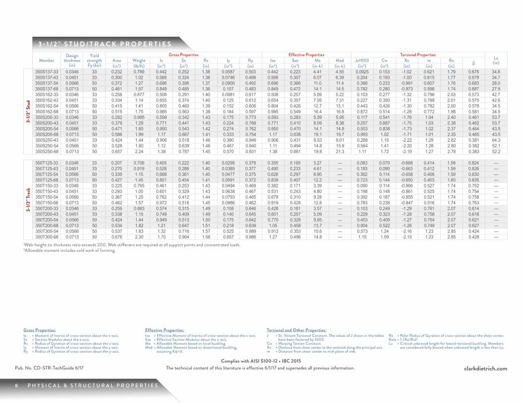
3 - 1 / 2 " S T U D / T R A C K P R O P E R T I E S
MemberDesign
thickness (in)
Yield strength Fy (ksi)
Gross Properties Effective Properties Torsional PropertiesLu
(in)Area Weight Ix Sx Rx Iy Ry Ixe Sxe Ma Mad Jx1000 Cw Xo m Ro β(in2) (lb/ft) (in4) (in3) (in) (in4) (in) (in4) (in3) (in-k) (in-k) (in4) (in6) (in) (in) (in)
3-1/
2" S
tud
350S137-33 0.0346 33 0.232 0.789 0.442 0.252 1.38 0.0587 0.503 0.442 0.223 4.41 4.55 0.0925 0.153 -1.02 0.621 1.79 0.676 34.8350S137-43 0.0451 33 0.300 1.02 0.568 0.324 1.38 0.0746 0.498 0.568 0.307 6.07 6.39 0.204 0.193 -1.00 0.615 1.77 0.679 34.7350S137-54 0.0566 50 0.372 1.27 0.696 0.398 1.37 0.0900 0.492 0.696 0.366 11.0 11.4 0.398 0.233 -0.991 0.607 1.76 0.683 28.0350S137-68 0.0713 50 0.461 1.57 0.849 0.485 1.36 0.107 0.483 0.849 0.472 14.1 14.5 0.782 0.280 -0.973 0.598 1.74 0.687 27.9350S162-33 0.0346 33 0.258 0.877 0.508 0.291 1.40 0.0981 0.617 0.508 0.257 5.09 5.22 0.103 0.277 -1.32 0.796 2.03 0.573 42.7350S162-43 0.0451 33 0.334 1.14 0.655 0.374 1.40 0.125 0.612 0.654 0.357 7.05 7.31 0.227 0.350 -1.31 0.789 2.01 0.575 42.6350S162-54 0.0566 50 0.415 1.41 0.805 0.460 1.39 0.152 0.606 0.804 0.426 12.7 13.1 0.443 0.426 -1.30 0.782 2.00 0.578 34.5350S162-68 0.0713 50 0.515 1.75 0.985 0.563 1.38 0.184 0.597 0.985 0.549 16.4 16.8 0.872 0.514 -1.28 0.772 1.98 0.581 34.5350S200-33 0.0346 33 0.292 0.995 0.599 0.342 1.43 0.175 0.773 0.593 0.283 5.59 5.95 0.117 0.541 -1.76 1.04 2.40 0.461 53.7350S200-43 0.0451 33 0.379 1.29 0.771 0.441 1.43 0.224 0.768 0.771 0.410 8.09 8.36 0.257 0.687 -1.75 1.03 2.38 0.462 53.7350S200-54 0.0566 50 0.471 1.60 0.950 0.543 1.42 0.274 0.762 0.950 0.470 14.1 14.9 0.503 0.838 -1.73 1.02 2.37 0.464 43.5350S200-68 0.0713 50 0.586 1.99 1.17 0.667 1.41 0.333 0.754 1.17 0.638 19.1 19.7 0.993 1.02 -1.71 1.01 2.35 0.465 43.5350S250-43 0.0451 33 0.424 1.44 0.906 0.518 1.46 0.380 0.946 0.906 0.431 8.53 9.01 0.288 1.15 -2.22 1.29 2.82 0.381 64.3350S250-54 0.0566 50 0.528 1.80 1.12 0.639 1.46 0.467 0.940 1.11 0.494 14.8 15.9 0.564 1.41 -2.20 1.28 2.80 0.382 52.1350S250-68 0.0713 50 0.657 2.24 1.38 0.787 1.45 0.570 0.931 1.38 0.661 19.8 21.3 1.11 1.72 -2.19 1.27 2.78 0.383 52.2
3-1/
2" Tr
ack
350T125-33 0.0346 33 0.207 0.706 0.405 0.222 1.40 0.0299 0.379 0.355 0.165 3.27 — 0.083 0.070 -0.668 0.414 1.59 0.824 —350T125-43 0.0451 33 0.270 0.919 0.528 0.288 1.40 0.0385 0.377 0.490 0.233 4.61 — 0.183 0.090 -0.663 0.412 1.59 0.826 —350T125-54 0.0566 50 0.339 1.15 0.668 0.361 1.40 0.0477 0.375 0.626 0.297 8.90 — 0.362 0.114 -0.658 0.408 1.59 0.830 —350T125-68 0.0713 50 0.427 1.45 0.851 0.454 1.41 0.0591 0.372 0.839 0.407 12.2 — 0.723 0.144 -0.650 0.403 1.60 0.835 —350T150-33 0.0346 33 0.225 0.765 0.461 0.253 1.43 0.0494 0.469 0.382 0.171 3.39 — 0.090 0.114 -0.866 0.527 1.74 0.752 —350T150-43 0.0451 33 0.293 1.00 0.601 0.329 1.43 0.0638 0.467 0.531 0.243 4.80 — 0.198 0.148 -0.861 0.525 1.74 0.754 —350T150-54 0.0566 50 0.367 1.25 0.762 0.412 1.44 0.0793 0.465 0.679 0.310 9.28 — 0.392 0.187 -0.855 0.521 1.74 0.758 —350T150-68 0.0713 50 0.462 1.57 0.972 0.518 1.45 0.0986 0.462 0.919 0.428 12.8 — 0.783 0.238 -0.847 0.516 1.74 0.763 —350T200-33 0.0346 33 0.259 0.883 0.574 0.315 1.49 0.108 0.646 0.428 0.181 3.57 — 0.103 0.249 -1.29 0.761 2.07 0.614 —350T200-43 0.0451 33 0.338 1.15 0.749 0.409 1.49 0.140 0.645 0.601 0.257 5.09 — 0.229 0.323 -1.28 0.758 2.07 0.616 —350T200-54 0.0566 50 0.424 1.44 0.949 0.513 1.50 0.175 0.642 0.770 0.329 9.85 — 0.453 0.409 -1.27 0.754 2.07 0.621 —350T200-68 0.0713 50 0.534 1.82 1.21 0.647 1.51 0.218 0.639 1.05 0.458 13.7 — 0.904 0.522 -1.26 0.749 2.07 0.627 —350T300-54 0.0566 50 0.537 1.83 1.32 0.716 1.57 0.525 0.989 0.912 0.353 10.6 — 0.573 1.24 -2.16 1.23 2.85 0.424 —350T300-68 0.0713 50 0.676 2.30 1.70 0.904 1.58 0.657 0.986 1.27 0.496 14.8 — 1.15 1.59 -2.15 1.23 2.85 0.428 —
1Web-height-to-thickness ratio exceeds 200. Web stiffeners are required at all support points and concentrated loads. *Allowable moment includes cold work of forming.
9 P H Y S I C A L & S T R U C T U R A L P R O P E R T I E S
clarkdietrich.comPub. No. CD-STR-TechGuide 6/17 The technical content of this literature is effective 6/1/17 and supersedes all previous information.Complies with AISI S100-12 • IBC 2015
Gross Properties:Ix = Moment of Inertia of cross-section about the x-axis.Sx = Section Modulus about the x-axis.Rx = Radius of Gyration of cross-section about the x-axis.Iy = Moment of Inertia of cross-section about the y-axis.Ry = Radius of Gyration of cross-section about the y-axis.
Effective Properties:Ixe = Effective Moment of Inertia of cross-section about the x-axis.Sxe = Effective Section Modulus about the x-axis.Ma = Allowable Moment based on local buckling.Mad = Allowable Moment based on distortional buckling,
assuming Kφ=0.
Torsional and Other Properties:J = St. Venant Torsional Constant. The values of J shown in the tables
have been factored by 1000.Cw = Warping Torsion Constant.Xo = Distance from shear center to the centroid along the principal axis.m = Distance from shear center to mid-plane of web.
Ro = Polar Radius of Gyration of cross-section about the shear center.Βeta = 1-(Xo/Ro).2Lu = Critical unbraced length for lateral-torsional buckling. Members
are considered fully braced when unbraced length is less than Lu.
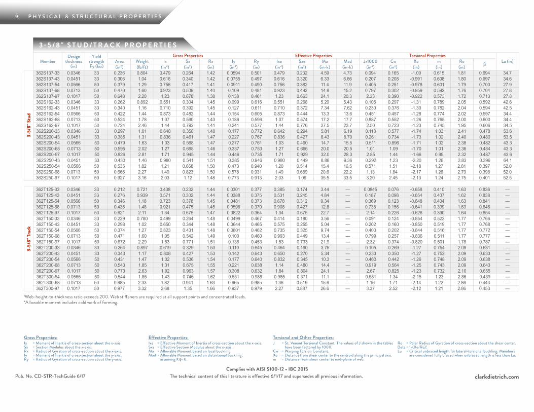
3 - 5 / 8 " S T U D / T R A C K P R O P E R T I E S
MemberDesign
thickness (in)
Yield strength Fy (ksi)
Gross Properties Effective Properties Torsional PropertiesLu (in)Area Weight Ix Sx Rx Iy Ry Ixe Sxe Ma Mad Jx1000 Cw Xo m Ro β(in2) (lb/ft) (in4) (in3) (in) (in4) (in) (in4) (in3) (in-k) (in-k) (in4) (in6) (in) (in) (in)
3-5/
8" S
tud
362S137-33 0.0346 33 0.236 0.804 0.479 0.264 1.42 0.0594 0.501 0.479 0.232 4.59 4.73 0.094 0.165 -1.00 0.615 1.81 0.694 34.7362S137-43 0.0451 33 0.306 1.04 0.616 0.340 1.42 0.0755 0.497 0.616 0.320 6.33 6.66 0.207 0.208 -0.991 0.608 1.80 0.697 34.6362S137-54 0.0566 50 0.379 1.29 0.756 0.417 1.41 0.0911 0.490 0.756 0.382 11.4 11.9 0.405 0.251 -0.978 0.601 1.79 0.700 27.9362S137-68 0.0713 50 0.470 1.60 0.923 0.509 1.40 0.109 0.481 0.923 0.493 14.8 15.2 0.797 0.302 -0.959 0.592 1.76 0.704 27.8362S137-97 0.1017 50 0.648 2.20 1.23 0.678 1.38 0.138 0.461 1.23 0.663 24.1 20.3 2.23 0.390 -0.922 0.573 1.72 0.713 27.8362S162-33 0.0346 33 0.262 0.892 0.551 0.304 1.45 0.099 0.616 0.551 0.268 5.29 5.43 0.105 0.297 -1.31 0.789 2.05 0.592 42.6362S162-43 0.0451 33 0.340 1.16 0.710 0.392 1.45 0.127 0.611 0.710 0.372 7.34 7.62 0.230 0.376 -1.30 0.782 2.04 0.594 42.5362S162-54 0.0566 50 0.422 1.44 0.873 0.482 1.44 0.154 0.605 0.873 0.444 13.3 13.6 0.451 0.457 -1.28 0.774 2.02 0.597 34.4362S162-68 0.0713 50 0.524 1.78 1.07 0.590 1.43 0.186 0.596 1.07 0.574 17.2 17.7 0.887 0.552 -1.26 0.765 2.00 0.600 34.4362S162-97 0.1017 50 0.724 2.46 1.44 0.792 1.41 0.241 0.577 1.44 0.776 27.5 23.7 2.50 0.723 -1.23 0.745 1.95 0.606 34.5362S200-33 0.0346 33 0.297 1.01 0.648 0.358 1.48 0.177 0.772 0.642 0.294 5.81 6.19 0.118 0.577 -1.74 1.03 2.41 0.478 53.6362S200-43 0.0451 33 0.385 1.31 0.836 0.461 1.47 0.227 0.767 0.836 0.427 8.43 8.70 0.261 0.734 -1.73 1.02 2.40 0.480 53.5362S200-54 0.0566 50 0.479 1.63 1.03 0.568 1.47 0.277 0.761 1.03 0.490 14.7 15.5 0.511 0.896 -1.71 1.02 2.38 0.482 43.3362S200-68 0.0713 50 0.595 2.02 1.27 0.698 1.46 0.337 0.753 1.27 0.666 20.0 20.5 1.01 1.09 -1.70 1.01 2.36 0.484 43.3362S200-97 0.1017 50 0.826 2.81 1.71 0.945 1.44 0.446 0.735 1.71 0.929 32.0 28.3 2.85 1.44 -1.66 0.99 2.32 0.487 43.6362S250-43 0.0451 33 0.430 1.46 0.980 0.541 1.51 0.385 0.946 0.980 0.449 8.88 9.36 0.292 1.23 -2.20 1.28 2.83 0.396 64.1362S250-54 0.0566 50 0.535 1.82 1.21 0.668 1.50 0.473 0.940 1.20 0.514 15.4 16.5 0.571 1.51 -2.18 1.27 2.81 0.397 52.0362S250-68 0.0713 50 0.666 2.27 1.49 0.823 1.50 0.578 0.931 1.49 0.689 20.6 22.2 1.13 1.84 -2.17 1.26 2.79 0.398 52.0362S250-97 0.1017 50 0.927 3.16 2.03 1.12 1.48 0.773 0.913 2.03 1.06 35.5 33.5 3.20 2.45 -2.13 1.24 2.75 0.401 52.5
3-5/
8" Tr
ack
362T125-33 0.0346 33 0.212 0.721 0.438 0.232 1.44 0.0301 0.377 0.385 0.174 3.44 — 0.0845 0.076 -0.658 0.410 1.63 0.836 —362T125-43 0.0451 33 0.276 0.939 0.571 0.302 1.44 0.0388 0.375 0.531 0.245 4.84 — 0.187 0.098 -0.654 0.407 1.62 0.838 —362T125-54 0.0566 50 0.346 1.18 0.723 0.378 1.45 0.0481 0.373 0.678 0.312 9.34 — 0.369 0.123 -0.648 0.404 1.63 0.841 —362T125-68 0.0713 50 0.436 1.48 0.921 0.475 1.45 0.0596 0.370 0.908 0.427 12.8 — 0.738 0.156 -0.641 0.399 1.63 0.846 —362T125-97 0.1017 50 0.621 2.11 1.34 0.675 1.47 0.0822 0.364 1.34 0.675 22.7 — 2.14 0.226 -0.626 0.390 1.64 0.854 —362T150-33 0.0346 33 0.229 0.780 0.499 0.264 1.48 0.0499 0.467 0.414 0.180 3.56 — 0.091 0.124 -0.854 0.522 1.77 0.766 —362T150-43 0.0451 33 0.298 1.02 0.650 0.344 1.48 0.0644 0.465 0.575 0.255 5.04 — 0.202 0.160 -0.850 0.519 1.77 0.768 —362T150-54 0.0566 50 0.374 1.27 0.823 0.431 1.48 0.0801 0.462 0.735 0.325 9.74 — 0.400 0.202 -0.844 0.516 1.77 0.772 —362T150-68 0.0713 50 0.471 1.60 1.05 0.542 1.49 0.100 0.460 0.993 0.449 13.4 — 0.799 0.257 -0.836 0.511 1.77 0.777 —362T150-97 0.1017 50 0.672 2.29 1.53 0.771 1.51 0.138 0.453 1.53 0.733 21.9 — 2.32 0.374 -0.820 0.501 1.78 0.787 —362T200-33 0.0346 33 0.264 0.897 0.619 0.329 1.53 0.110 0.645 0.464 0.190 3.76 — 0.105 0.269 -1.27 0.754 2.09 0.631 —362T200-43 0.0451 33 0.343 1.17 0.808 0.427 1.53 0.142 0.643 0.650 0.270 5.34 — 0.233 0.350 -1.27 0.752 2.09 0.633 —362T200-54 0.0566 50 0.431 1.47 1.02 0.536 1.54 0.177 0.640 0.832 0.345 10.3 — 0.460 0.442 -1.26 0.748 2.09 0.638 —362T200-68 0.0713 50 0.543 1.85 1.31 0.675 1.55 0.221 0.638 1.14 0.480 14.4 — 0.919 0.564 -1.25 0.743 2.09 0.643 —362T200-97 0.1017 50 0.773 2.63 1.92 0.963 1.57 0.308 0.632 1.84 0.804 24.1 — 2.67 0.825 -1.23 0.732 2.10 0.655 —362T300-54 0.0566 50 0.544 1.85 1.43 0.746 1.62 0.531 0.988 0.985 0.371 11.1 — 0.581 1.34 -2.15 1.23 2.86 0.439 —362T300-68 0.0713 50 0.685 2.33 1.82 0.941 1.63 0.665 0.985 1.36 0.519 15.6 — 1.16 1.71 -2.14 1.22 2.86 0.443 —362T300-97 0.1017 50 0.977 3.32 2.68 1.35 1.66 0.937 0.979 2.27 0.887 26.6 — 3.37 2.52 -2.12 1.21 2.86 0.453 —
1Web-height-to-thickness ratio exceeds 200. Web stiffeners are required at all support points and concentrated loads. *Allowable moment includes cold work of forming.
10 P H Y S I C A L & S T R U C T U R A L P R O P E R T I E S
clarkdietrich.comThe technical content of this literature is effective 6/1/17 and supersedes all previous information.
Gross Properties:Ix = Moment of Inertia of cross-section about the x-axis.Sx = Section Modulus about the x-axis.Rx = Radius of Gyration of cross-section about the x-axis.Iy = Moment of Inertia of cross-section about the y-axis.Ry = Radius of Gyration of cross-section about the y-axis.
Effective Properties:Ixe = Effective Moment of Inertia of cross-section about the x-axis.Sxe = Effective Section Modulus about the x-axis.Ma = Allowable Moment based on local buckling.Mad = Allowable Moment based on distortional buckling,
assuming Kφ=0.
Torsional and Other Properties:J = St. Venant Torsional Constant. The values of J shown in the tables
have been factored by 1000.Cw = Warping Torsion Constant.Xo = Distance from shear center to the centroid along the principal axis.m = Distance from shear center to mid-plane of web.
Ro = Polar Radius of Gyration of cross-section about the shear center.Βeta = 1-(Xo/Ro).2Lu = Critical unbraced length for lateral-torsional buckling. Members
are considered fully braced when unbraced length is less than Lu.
Pub. No. CD-STR-TechGuide 6/17Complies with AISI S100-12 • IBC 2015
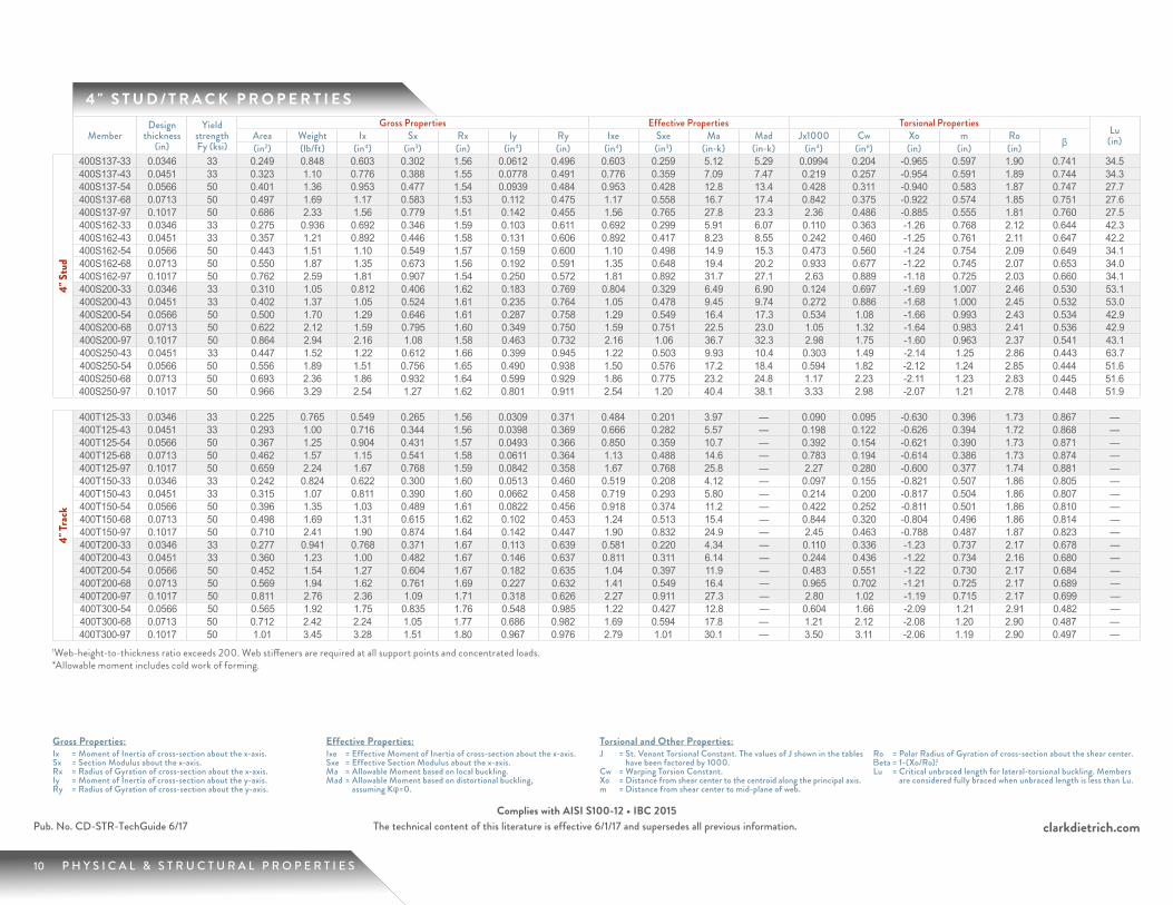
4 " S T U D / T R A C K P R O P E R T I E S
MemberDesign
thickness (in)
Yield strength Fy (ksi)
Gross Properties Effective Properties Torsional PropertiesLu
(in)Area Weight Ix Sx Rx Iy Ry Ixe Sxe Ma Mad Jx1000 Cw Xo m Ro β(in2) (lb/ft) (in4) (in3) (in) (in4) (in) (in4) (in3) (in-k) (in-k) (in4) (in6) (in) (in) (in)
4" S
tud
400S137-33 0.0346 33 0.249 0.848 0.603 0.302 1.56 0.0612 0.496 0.603 0.259 5.12 5.29 0.0994 0.204 -0.965 0.597 1.90 0.741 34.5400S137-43 0.0451 33 0.323 1.10 0.776 0.388 1.55 0.0778 0.491 0.776 0.359 7.09 7.47 0.219 0.257 -0.954 0.591 1.89 0.744 34.3400S137-54 0.0566 50 0.401 1.36 0.953 0.477 1.54 0.0939 0.484 0.953 0.428 12.8 13.4 0.428 0.311 -0.940 0.583 1.87 0.747 27.7400S137-68 0.0713 50 0.497 1.69 1.17 0.583 1.53 0.112 0.475 1.17 0.558 16.7 17.4 0.842 0.375 -0.922 0.574 1.85 0.751 27.6400S137-97 0.1017 50 0.686 2.33 1.56 0.779 1.51 0.142 0.455 1.56 0.765 27.8 23.3 2.36 0.486 -0.885 0.555 1.81 0.760 27.5400S162-33 0.0346 33 0.275 0.936 0.692 0.346 1.59 0.103 0.611 0.692 0.299 5.91 6.07 0.110 0.363 -1.26 0.768 2.12 0.644 42.3400S162-43 0.0451 33 0.357 1.21 0.892 0.446 1.58 0.131 0.606 0.892 0.417 8.23 8.55 0.242 0.460 -1.25 0.761 2.11 0.647 42.2400S162-54 0.0566 50 0.443 1.51 1.10 0.549 1.57 0.159 0.600 1.10 0.498 14.9 15.3 0.473 0.560 -1.24 0.754 2.09 0.649 34.1400S162-68 0.0713 50 0.550 1.87 1.35 0.673 1.56 0.192 0.591 1.35 0.648 19.4 20.2 0.933 0.677 -1.22 0.745 2.07 0.653 34.0400S162-97 0.1017 50 0.762 2.59 1.81 0.907 1.54 0.250 0.572 1.81 0.892 31.7 27.1 2.63 0.889 -1.18 0.725 2.03 0.660 34.1400S200-33 0.0346 33 0.310 1.05 0.812 0.406 1.62 0.183 0.769 0.804 0.329 6.49 6.90 0.124 0.697 -1.69 1.007 2.46 0.530 53.1400S200-43 0.0451 33 0.402 1.37 1.05 0.524 1.61 0.235 0.764 1.05 0.478 9.45 9.74 0.272 0.886 -1.68 1.000 2.45 0.532 53.0400S200-54 0.0566 50 0.500 1.70 1.29 0.646 1.61 0.287 0.758 1.29 0.549 16.4 17.3 0.534 1.08 -1.66 0.993 2.43 0.534 42.9400S200-68 0.0713 50 0.622 2.12 1.59 0.795 1.60 0.349 0.750 1.59 0.751 22.5 23.0 1.05 1.32 -1.64 0.983 2.41 0.536 42.9400S200-97 0.1017 50 0.864 2.94 2.16 1.08 1.58 0.463 0.732 2.16 1.06 36.7 32.3 2.98 1.75 -1.60 0.963 2.37 0.541 43.1400S250-43 0.0451 33 0.447 1.52 1.22 0.612 1.66 0.399 0.945 1.22 0.503 9.93 10.4 0.303 1.49 -2.14 1.25 2.86 0.443 63.7400S250-54 0.0566 50 0.556 1.89 1.51 0.756 1.65 0.490 0.938 1.50 0.576 17.2 18.4 0.594 1.82 -2.12 1.24 2.85 0.444 51.6400S250-68 0.0713 50 0.693 2.36 1.86 0.932 1.64 0.599 0.929 1.86 0.775 23.2 24.8 1.17 2.23 -2.11 1.23 2.83 0.445 51.6400S250-97 0.1017 50 0.966 3.29 2.54 1.27 1.62 0.801 0.911 2.54 1.20 40.4 38.1 3.33 2.98 -2.07 1.21 2.78 0.448 51.9
4" Tr
ack
400T125-33 0.0346 33 0.225 0.765 0.549 0.265 1.56 0.0309 0.371 0.484 0.201 3.97 — 0.090 0.095 -0.630 0.396 1.73 0.867 —400T125-43 0.0451 33 0.293 1.00 0.716 0.344 1.56 0.0398 0.369 0.666 0.282 5.57 — 0.198 0.122 -0.626 0.394 1.72 0.868 —400T125-54 0.0566 50 0.367 1.25 0.904 0.431 1.57 0.0493 0.366 0.850 0.359 10.7 — 0.392 0.154 -0.621 0.390 1.73 0.871 —400T125-68 0.0713 50 0.462 1.57 1.15 0.541 1.58 0.0611 0.364 1.13 0.488 14.6 — 0.783 0.194 -0.614 0.386 1.73 0.874 —400T125-97 0.1017 50 0.659 2.24 1.67 0.768 1.59 0.0842 0.358 1.67 0.768 25.8 — 2.27 0.280 -0.600 0.377 1.74 0.881 —400T150-33 0.0346 33 0.242 0.824 0.622 0.300 1.60 0.0513 0.460 0.519 0.208 4.12 — 0.097 0.155 -0.821 0.507 1.86 0.805 —400T150-43 0.0451 33 0.315 1.07 0.811 0.390 1.60 0.0662 0.458 0.719 0.293 5.80 — 0.214 0.200 -0.817 0.504 1.86 0.807 —400T150-54 0.0566 50 0.396 1.35 1.03 0.489 1.61 0.0822 0.456 0.918 0.374 11.2 — 0.422 0.252 -0.811 0.501 1.86 0.810 —400T150-68 0.0713 50 0.498 1.69 1.31 0.615 1.62 0.102 0.453 1.24 0.513 15.4 — 0.844 0.320 -0.804 0.496 1.86 0.814 —400T150-97 0.1017 50 0.710 2.41 1.90 0.874 1.64 0.142 0.447 1.90 0.832 24.9 — 2.45 0.463 -0.788 0.487 1.87 0.823 —400T200-33 0.0346 33 0.277 0.941 0.768 0.371 1.67 0.113 0.639 0.581 0.220 4.34 — 0.110 0.336 -1.23 0.737 2.17 0.678 —400T200-43 0.0451 33 0.360 1.23 1.00 0.482 1.67 0.146 0.637 0.811 0.311 6.14 — 0.244 0.436 -1.22 0.734 2.16 0.680 —400T200-54 0.0566 50 0.452 1.54 1.27 0.604 1.67 0.182 0.635 1.04 0.397 11.9 — 0.483 0.551 -1.22 0.730 2.17 0.684 —400T200-68 0.0713 50 0.569 1.94 1.62 0.761 1.69 0.227 0.632 1.41 0.549 16.4 — 0.965 0.702 -1.21 0.725 2.17 0.689 —400T200-97 0.1017 50 0.811 2.76 2.36 1.09 1.71 0.318 0.626 2.27 0.911 27.3 — 2.80 1.02 -1.19 0.715 2.17 0.699 —400T300-54 0.0566 50 0.565 1.92 1.75 0.835 1.76 0.548 0.985 1.22 0.427 12.8 — 0.604 1.66 -2.09 1.21 2.91 0.482 —400T300-68 0.0713 50 0.712 2.42 2.24 1.05 1.77 0.686 0.982 1.69 0.594 17.8 — 1.21 2.12 -2.08 1.20 2.90 0.487 —400T300-97 0.1017 50 1.01 3.45 3.28 1.51 1.80 0.967 0.976 2.79 1.01 30.1 — 3.50 3.11 -2.06 1.19 2.90 0.497 —
1Web-height-to-thickness ratio exceeds 200. Web stiffeners are required at all support points and concentrated loads. *Allowable moment includes cold work of forming.
11 P H Y S I C A L & S T R U C T U R A L P R O P E R T I E S
clarkdietrich.comPub. No. CD-STR-TechGuide 6/17 The technical content of this literature is effective 6/1/17 and supersedes all previous information.Complies with AISI S100-12 • IBC 2015
Gross Properties:Ix = Moment of Inertia of cross-section about the x-axis.Sx = Section Modulus about the x-axis.Rx = Radius of Gyration of cross-section about the x-axis.Iy = Moment of Inertia of cross-section about the y-axis.Ry = Radius of Gyration of cross-section about the y-axis.
Effective Properties:Ixe = Effective Moment of Inertia of cross-section about the x-axis.Sxe = Effective Section Modulus about the x-axis.Ma = Allowable Moment based on local buckling.Mad = Allowable Moment based on distortional buckling,
assuming Kφ=0.
Torsional and Other Properties:J = St. Venant Torsional Constant. The values of J shown in the tables
have been factored by 1000.Cw = Warping Torsion Constant.Xo = Distance from shear center to the centroid along the principal axis.m = Distance from shear center to mid-plane of web.
Ro = Polar Radius of Gyration of cross-section about the shear center.Βeta = 1-(Xo/Ro).2Lu = Critical unbraced length for lateral-torsional buckling. Members
are considered fully braced when unbraced length is less than Lu.
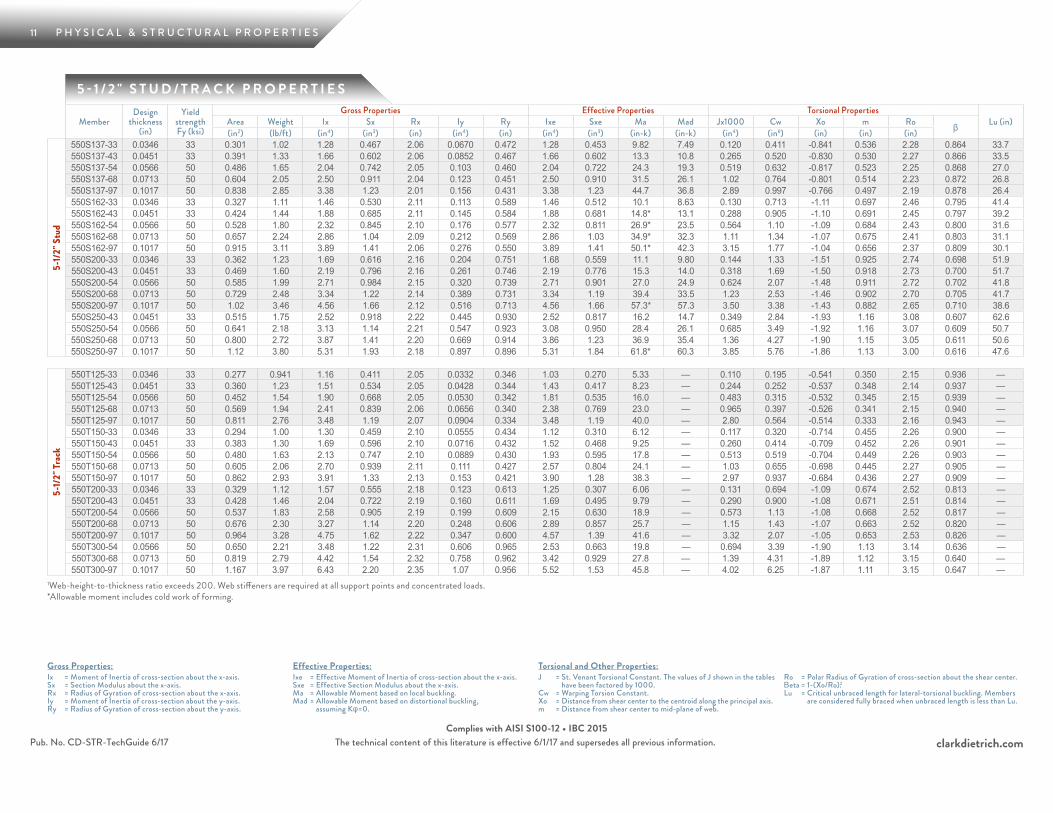
5 - 1 / 2 " S T U D / T R A C K P R O P E R T I E S
MemberDesign
thickness (in)
Yield strength Fy (ksi)
Gross Properties Effective Properties Torsional PropertiesLu (in)Area Weight Ix Sx Rx Iy Ry Ixe Sxe Ma Mad Jx1000 Cw Xo m Ro β(in2) (lb/ft) (in4) (in3) (in) (in4) (in) (in4) (in3) (in-k) (in-k) (in4) (in6) (in) (in) (in)
5-1/
2" S
tud
550S137-33 0.0346 33 0.301 1.02 1.28 0.467 2.06 0.0670 0.472 1.28 0.453 9.82 7.49 0.120 0.411 -0.841 0.536 2.28 0.864 33.7550S137-43 0.0451 33 0.391 1.33 1.66 0.602 2.06 0.0852 0.467 1.66 0.602 13.3 10.8 0.265 0.520 -0.830 0.530 2.27 0.866 33.5550S137-54 0.0566 50 0.486 1.65 2.04 0.742 2.05 0.103 0.460 2.04 0.722 24.3 19.3 0.519 0.632 -0.817 0.523 2.25 0.868 27.0550S137-68 0.0713 50 0.604 2.05 2.50 0.911 2.04 0.123 0.451 2.50 0.910 31.5 26.1 1.02 0.764 -0.801 0.514 2.23 0.872 26.8550S137-97 0.1017 50 0.838 2.85 3.38 1.23 2.01 0.156 0.431 3.38 1.23 44.7 36.8 2.89 0.997 -0.766 0.497 2.19 0.878 26.4550S162-33 0.0346 33 0.327 1.11 1.46 0.530 2.11 0.113 0.589 1.46 0.512 10.1 8.63 0.130 0.713 -1.11 0.697 2.46 0.795 41.4550S162-43 0.0451 33 0.424 1.44 1.88 0.685 2.11 0.145 0.584 1.88 0.681 14.8* 13.1 0.288 0.905 -1.10 0.691 2.45 0.797 39.2550S162-54 0.0566 50 0.528 1.80 2.32 0.845 2.10 0.176 0.577 2.32 0.811 26.9* 23.5 0.564 1.10 -1.09 0.684 2.43 0.800 31.6550S162-68 0.0713 50 0.657 2.24 2.86 1.04 2.09 0.212 0.569 2.86 1.03 34.9* 32.3 1.11 1.34 -1.07 0.675 2.41 0.803 31.1550S162-97 0.1017 50 0.915 3.11 3.89 1.41 2.06 0.276 0.550 3.89 1.41 50.1* 42.3 3.15 1.77 -1.04 0.656 2.37 0.809 30.1550S200-33 0.0346 33 0.362 1.23 1.69 0.616 2.16 0.204 0.751 1.68 0.559 11.1 9.80 0.144 1.33 -1.51 0.925 2.74 0.698 51.9550S200-43 0.0451 33 0.469 1.60 2.19 0.796 2.16 0.261 0.746 2.19 0.776 15.3 14.0 0.318 1.69 -1.50 0.918 2.73 0.700 51.7550S200-54 0.0566 50 0.585 1.99 2.71 0.984 2.15 0.320 0.739 2.71 0.901 27.0 24.9 0.624 2.07 -1.48 0.911 2.72 0.702 41.8550S200-68 0.0713 50 0.729 2.48 3.34 1.22 2.14 0.389 0.731 3.34 1.19 39.4 33.5 1.23 2.53 -1.46 0.902 2.70 0.705 41.7550S200-97 0.1017 50 1.02 3.46 4.56 1.66 2.12 0.516 0.713 4.56 1.66 57.3* 57.3 3.50 3.38 -1.43 0.882 2.65 0.710 38.6550S250-43 0.0451 33 0.515 1.75 2.52 0.918 2.22 0.445 0.930 2.52 0.817 16.2 14.7 0.349 2.84 -1.93 1.16 3.08 0.607 62.6550S250-54 0.0566 50 0.641 2.18 3.13 1.14 2.21 0.547 0.923 3.08 0.950 28.4 26.1 0.685 3.49 -1.92 1.16 3.07 0.609 50.7550S250-68 0.0713 50 0.800 2.72 3.87 1.41 2.20 0.669 0.914 3.86 1.23 36.9 35.4 1.36 4.27 -1.90 1.15 3.05 0.611 50.6550S250-97 0.1017 50 1.12 3.80 5.31 1.93 2.18 0.897 0.896 5.31 1.84 61.8* 60.3 3.85 5.76 -1.86 1.13 3.00 0.616 47.6
5-1/
2" Tr
ack
550T125-33 0.0346 33 0.277 0.941 1.16 0.411 2.05 0.0332 0.346 1.03 0.270 5.33 — 0.110 0.195 -0.541 0.350 2.15 0.936 —550T125-43 0.0451 33 0.360 1.23 1.51 0.534 2.05 0.0428 0.344 1.43 0.417 8.23 — 0.244 0.252 -0.537 0.348 2.14 0.937 —550T125-54 0.0566 50 0.452 1.54 1.90 0.668 2.05 0.0530 0.342 1.81 0.535 16.0 — 0.483 0.315 -0.532 0.345 2.15 0.939 —550T125-68 0.0713 50 0.569 1.94 2.41 0.839 2.06 0.0656 0.340 2.38 0.769 23.0 — 0.965 0.397 -0.526 0.341 2.15 0.940 —550T125-97 0.1017 50 0.811 2.76 3.48 1.19 2.07 0.0904 0.334 3.48 1.19 40.0 — 2.80 0.564 -0.514 0.333 2.16 0.943 —550T150-33 0.0346 33 0.294 1.00 1.30 0.459 2.10 0.0555 0.434 1.12 0.310 6.12 — 0.117 0.320 -0.714 0.455 2.26 0.900 —550T150-43 0.0451 33 0.383 1.30 1.69 0.596 2.10 0.0716 0.432 1.52 0.468 9.25 — 0.260 0.414 -0.709 0.452 2.26 0.901 —550T150-54 0.0566 50 0.480 1.63 2.13 0.747 2.10 0.0889 0.430 1.93 0.595 17.8 — 0.513 0.519 -0.704 0.449 2.26 0.903 —550T150-68 0.0713 50 0.605 2.06 2.70 0.939 2.11 0.111 0.427 2.57 0.804 24.1 — 1.03 0.655 -0.698 0.445 2.27 0.905 —550T150-97 0.1017 50 0.862 2.93 3.91 1.33 2.13 0.153 0.421 3.90 1.28 38.3 — 2.97 0.937 -0.684 0.436 2.27 0.909 —550T200-33 0.0346 33 0.329 1.12 1.57 0.555 2.18 0.123 0.613 1.25 0.307 6.06 — 0.131 0.694 -1.09 0.674 2.52 0.813 —550T200-43 0.0451 33 0.428 1.46 2.04 0.722 2.19 0.160 0.611 1.69 0.495 9.79 — 0.290 0.900 -1.08 0.671 2.51 0.814 —550T200-54 0.0566 50 0.537 1.83 2.58 0.905 2.19 0.199 0.609 2.15 0.630 18.9 — 0.573 1.13 -1.08 0.668 2.52 0.817 —550T200-68 0.0713 50 0.676 2.30 3.27 1.14 2.20 0.248 0.606 2.89 0.857 25.7 — 1.15 1.43 -1.07 0.663 2.52 0.820 —550T200-97 0.1017 50 0.964 3.28 4.75 1.62 2.22 0.347 0.600 4.57 1.39 41.6 — 3.32 2.07 -1.05 0.653 2.53 0.826 —550T300-54 0.0566 50 0.650 2.21 3.48 1.22 2.31 0.606 0.965 2.53 0.663 19.8 — 0.694 3.39 -1.90 1.13 3.14 0.636 —550T300-68 0.0713 50 0.819 2.79 4.42 1.54 2.32 0.758 0.962 3.42 0.929 27.8 — 1.39 4.31 -1.89 1.12 3.15 0.640 —550T300-97 0.1017 50 1.167 3.97 6.43 2.20 2.35 1.07 0.956 5.52 1.53 45.8 — 4.02 6.25 -1.87 1.11 3.15 0.647 —
1Web-height-to-thickness ratio exceeds 200. Web stiffeners are required at all support points and concentrated loads. *Allowable moment includes cold work of forming.
12 P H Y S I C A L & S T R U C T U R A L P R O P E R T I E S
clarkdietrich.comThe technical content of this literature is effective 6/1/17 and supersedes all previous information.
Gross Properties:Ix = Moment of Inertia of cross-section about the x-axis.Sx = Section Modulus about the x-axis.Rx = Radius of Gyration of cross-section about the x-axis.Iy = Moment of Inertia of cross-section about the y-axis.Ry = Radius of Gyration of cross-section about the y-axis.
Effective Properties:Ixe = Effective Moment of Inertia of cross-section about the x-axis.Sxe = Effective Section Modulus about the x-axis.Ma = Allowable Moment based on local buckling.Mad = Allowable Moment based on distortional buckling,
assuming Kφ=0.
Torsional and Other Properties:J = St. Venant Torsional Constant. The values of J shown in the tables
have been factored by 1000.Cw = Warping Torsion Constant.Xo = Distance from shear center to the centroid along the principal axis.m = Distance from shear center to mid-plane of web.
Ro = Polar Radius of Gyration of cross-section about the shear center.Βeta = 1-(Xo/Ro).2Lu = Critical unbraced length for lateral-torsional buckling. Members
are considered fully braced when unbraced length is less than Lu.
Pub. No. CD-STR-TechGuide 6/17Complies with AISI S100-12 • IBC 2015
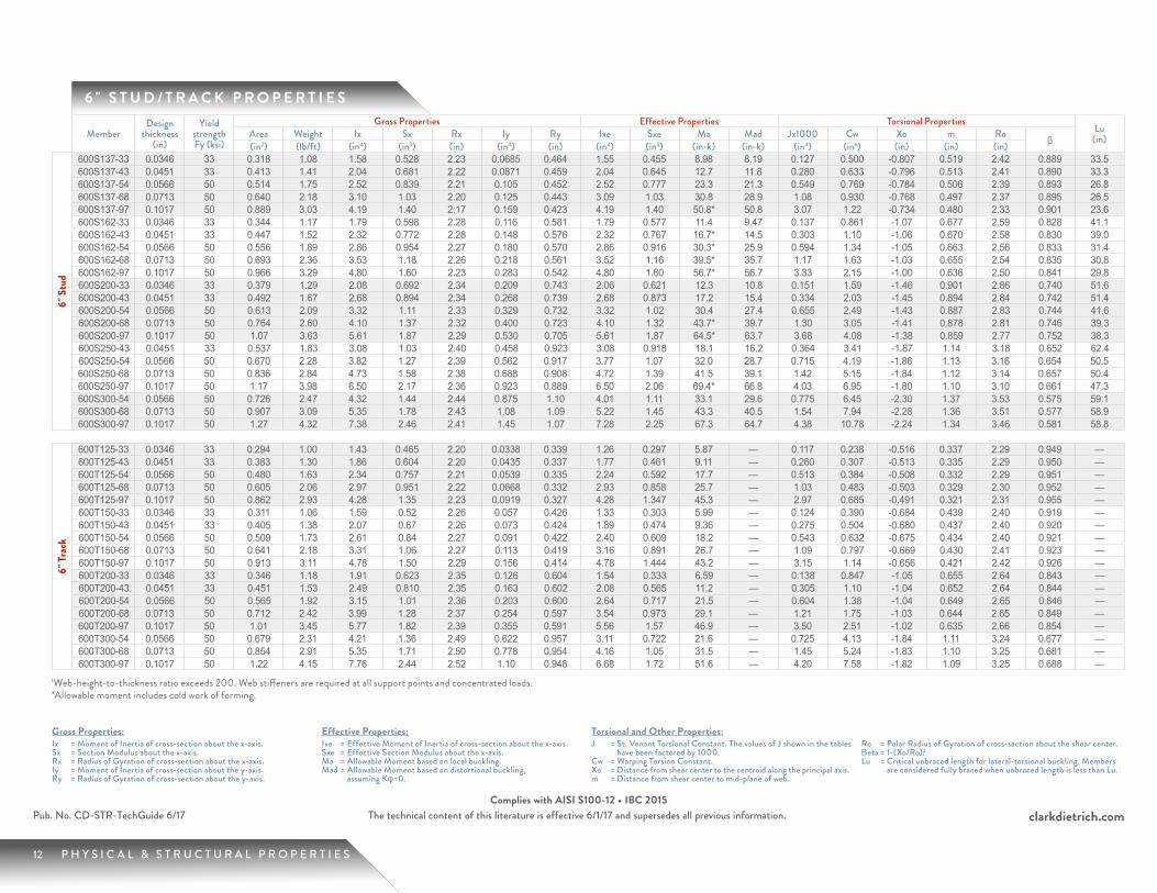
6 " S T U D / T R A C K P R O P E R T I E S
MemberDesign
thickness (in)
Yield strength Fy (ksi)
Gross Properties Effective Properties Torsional PropertiesLu
(in)Area Weight Ix Sx Rx Iy Ry Ixe Sxe Ma Mad Jx1000 Cw Xo m Ro β(in2) (lb/ft) (in4) (in3) (in) (in4) (in) (in4) (in3) (in-k) (in-k) (in4) (in6) (in) (in) (in)
6" S
tud
600S137-33 0.0346 33 0.318 1.08 1.58 0.528 2.23 0.0685 0.464 1.55 0.455 8.98 8.19 0.127 0.500 -0.807 0.519 2.42 0.889 33.5600S137-43 0.0451 33 0.413 1.41 2.04 0.681 2.22 0.0871 0.459 2.04 0.645 12.7 11.8 0.280 0.633 -0.796 0.513 2.41 0.890 33.3600S137-54 0.0566 50 0.514 1.75 2.52 0.839 2.21 0.105 0.452 2.52 0.777 23.3 21.3 0.549 0.769 -0.784 0.506 2.39 0.893 26.8600S137-68 0.0713 50 0.640 2.18 3.10 1.03 2.20 0.125 0.443 3.09 1.03 30.8 28.9 1.08 0.930 -0.768 0.497 2.37 0.895 26.5600S137-97 0.1017 50 0.889 3.03 4.19 1.40 2.17 0.159 0.423 4.19 1.40 50.8* 50.8 3.07 1.22 -0.734 0.480 2.33 0.901 23.6600S162-33 0.0346 33 0.344 1.17 1.79 0.598 2.28 0.116 0.581 1.79 0.577 11.4 9.47 0.137 0.861 -1.07 0.677 2.59 0.828 41.1600S162-43 0.0451 33 0.447 1.52 2.32 0.772 2.28 0.148 0.576 2.32 0.767 16.7* 14.5 0.303 1.10 -1.06 0.670 2.58 0.830 39.0600S162-54 0.0566 50 0.556 1.89 2.86 0.954 2.27 0.180 0.570 2.86 0.916 30.3* 25.9 0.594 1.34 -1.05 0.663 2.56 0.833 31.4600S162-68 0.0713 50 0.693 2.36 3.53 1.18 2.26 0.218 0.561 3.52 1.16 39.5* 35.7 1.17 1.63 -1.03 0.655 2.54 0.835 30.8600S162-97 0.1017 50 0.966 3.29 4.80 1.60 2.23 0.283 0.542 4.80 1.60 56.7* 56.7 3.33 2.15 -1.00 0.636 2.50 0.841 29.8600S200-33 0.0346 33 0.379 1.29 2.08 0.692 2.34 0.209 0.743 2.06 0.621 12.3 10.8 0.151 1.59 -1.46 0.901 2.86 0.740 51.6600S200-43 0.0451 33 0.492 1.67 2.68 0.894 2.34 0.268 0.739 2.68 0.873 17.2 15.4 0.334 2.03 -1.45 0.894 2.84 0.742 51.4600S200-54 0.0566 50 0.613 2.09 3.32 1.11 2.33 0.329 0.732 3.32 1.02 30.4 27.4 0.655 2.49 -1.43 0.887 2.83 0.744 41.6600S200-68 0.0713 50 0.764 2.60 4.10 1.37 2.32 0.400 0.723 4.10 1.32 43.7* 39.7 1.30 3.05 -1.41 0.878 2.81 0.746 39.3600S200-97 0.1017 50 1.07 3.63 5.61 1.87 2.29 0.530 0.705 5.61 1.87 64.5* 63.7 3.68 4.08 -1.38 0.859 2.77 0.752 38.3600S250-43 0.0451 33 0.537 1.83 3.08 1.03 2.40 0.458 0.923 3.08 0.918 18.1 16.2 0.364 3.41 -1.87 1.14 3.18 0.652 62.4600S250-54 0.0566 50 0.670 2.28 3.82 1.27 2.39 0.562 0.917 3.77 1.07 32.0 28.7 0.715 4.19 -1.86 1.13 3.16 0.654 50.5600S250-68 0.0713 50 0.836 2.84 4.73 1.58 2.38 0.688 0.908 4.72 1.39 41.5 39.1 1.42 5.15 -1.84 1.12 3.14 0.657 50.4600S250-97 0.1017 50 1.17 3.98 6.50 2.17 2.36 0.923 0.889 6.50 2.06 69.4* 66.8 4.03 6.95 -1.80 1.10 3.10 0.661 47.3600S300-54 0.0566 50 0.726 2.47 4.32 1.44 2.44 0.875 1.10 4.01 1.11 33.1 29.6 0.775 6.45 -2.30 1.37 3.53 0.575 59.1600S300-68 0.0713 50 0.907 3.09 5.35 1.78 2.43 1.08 1.09 5.22 1.45 43.3 40.5 1.54 7.94 -2.28 1.36 3.51 0.577 58.9600S300-97 0.1017 50 1.27 4.32 7.38 2.46 2.41 1.45 1.07 7.28 2.25 67.3 64.7 4.38 10.78 -2.24 1.34 3.46 0.581 58.8
6" Tr
ack
600T125-33 0.0346 33 0.294 1.00 1.43 0.465 2.20 0.0338 0.339 1.26 0.297 5.87 — 0.117 0.238 -0.516 0.337 2.29 0.949 —600T125-43 0.0451 33 0.383 1.30 1.86 0.604 2.20 0.0435 0.337 1.77 0.461 9.11 — 0.260 0.307 -0.513 0.335 2.29 0.950 —600T125-54 0.0566 50 0.480 1.63 2.34 0.757 2.21 0.0539 0.335 2.24 0.592 17.7 — 0.513 0.384 -0.508 0.332 2.29 0.951 —600T125-68 0.0713 50 0.605 2.06 2.97 0.951 2.22 0.0668 0.332 2.93 0.858 25.7 — 1.03 0.483 -0.503 0.329 2.30 0.952 —600T125-97 0.1017 50 0.862 2.93 4.28 1.35 2.23 0.0919 0.327 4.28 1.347 45.3 — 2.97 0.685 -0.491 0.321 2.31 0.955 —600T150-33 0.0346 33 0.311 1.06 1.59 0.52 2.26 0.057 0.426 1.33 0.303 5.99 — 0.124 0.390 -0.684 0.439 2.40 0.919 —600T150-43 0.0451 33 0.405 1.38 2.07 0.67 2.26 0.073 0.424 1.89 0.474 9.36 — 0.275 0.504 -0.680 0.437 2.40 0.920 —600T150-54 0.0566 50 0.509 1.73 2.61 0.84 2.27 0.091 0.422 2.40 0.609 18.2 — 0.543 0.632 -0.675 0.434 2.40 0.921 —600T150-68 0.0713 50 0.641 2.18 3.31 1.06 2.27 0.113 0.419 3.16 0.891 26.7 — 1.09 0.797 -0.669 0.430 2.41 0.923 —600T150-97 0.1017 50 0.913 3.11 4.78 1.50 2.29 0.156 0.414 4.78 1.444 43.2 — 3.15 1.14 -0.656 0.421 2.42 0.926 —600T200-33 0.0346 33 0.346 1.18 1.91 0.623 2.35 0.126 0.604 1.54 0.333 6.59 — 0.138 0.847 -1.05 0.655 2.64 0.843 —600T200-43 0.0451 33 0.451 1.53 2.49 0.810 2.35 0.163 0.602 2.08 0.565 11.2 — 0.305 1.10 -1.04 0.652 2.64 0.844 —600T200-54 0.0566 50 0.565 1.92 3.15 1.01 2.36 0.203 0.600 2.64 0.717 21.5 — 0.604 1.38 -1.04 0.649 2.65 0.846 —600T200-68 0.0713 50 0.712 2.42 3.99 1.28 2.37 0.254 0.597 3.54 0.973 29.1 — 1.21 1.75 -1.03 0.644 2.65 0.849 —600T200-97 0.1017 50 1.01 3.45 5.77 1.82 2.39 0.355 0.591 5.56 1.57 46.9 — 3.50 2.51 -1.02 0.635 2.66 0.854 —600T300-54 0.0566 50 0.679 2.31 4.21 1.36 2.49 0.622 0.957 3.11 0.722 21.6 — 0.725 4.13 -1.84 1.11 3.24 0.677 —600T300-68 0.0713 50 0.854 2.91 5.35 1.71 2.50 0.778 0.954 4.16 1.05 31.5 — 1.45 5.24 -1.83 1.10 3.25 0.681 —600T300-97 0.1017 50 1.22 4.15 7.76 2.44 2.52 1.10 0.948 6.68 1.72 51.6 — 4.20 7.58 -1.82 1.09 3.25 0.688 —
1Web-height-to-thickness ratio exceeds 200. Web stiffeners are required at all support points and concentrated loads. *Allowable moment includes cold work of forming.
13 P H Y S I C A L & S T R U C T U R A L P R O P E R T I E S
clarkdietrich.comPub. No. CD-STR-TechGuide 6/17 The technical content of this literature is effective 6/1/17 and supersedes all previous information.Complies with AISI S100-12 • IBC 2015
Gross Properties:Ix = Moment of Inertia of cross-section about the x-axis.Sx = Section Modulus about the x-axis.Rx = Radius of Gyration of cross-section about the x-axis.Iy = Moment of Inertia of cross-section about the y-axis.Ry = Radius of Gyration of cross-section about the y-axis.
Effective Properties:Ixe = Effective Moment of Inertia of cross-section about the x-axis.Sxe = Effective Section Modulus about the x-axis.Ma = Allowable Moment based on local buckling.Mad = Allowable Moment based on distortional buckling,
assuming Kφ=0.
Torsional and Other Properties:J = St. Venant Torsional Constant. The values of J shown in the tables
have been factored by 1000.Cw = Warping Torsion Constant.Xo = Distance from shear center to the centroid along the principal axis.m = Distance from shear center to mid-plane of web.
Ro = Polar Radius of Gyration of cross-section about the shear center.Βeta = 1-(Xo/Ro).2Lu = Critical unbraced length for lateral-torsional buckling. Members
are considered fully braced when unbraced length is less than Lu.
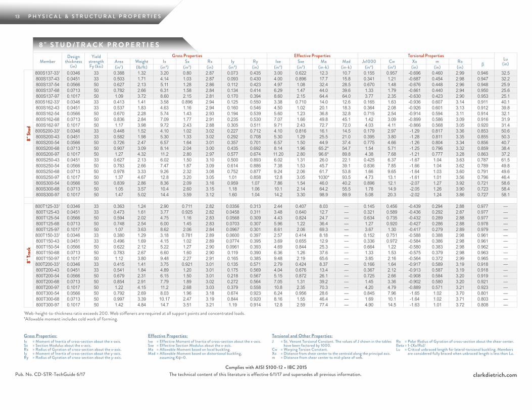
8 " S T U D / T R A C K P R O P E R T I E S
MemberDesign
thickness (in)
Yield strength Fy (ksi)
Gross Properties Effective Properties Torsional PropertiesLu
(in)Area Weight Ix Sx Rx Iy Ry Ixe Sxe Ma Mad Jx1000 Cw Xo m Ro β(in2) (lb/ft) (in4) (in3) (in) (in4) (in) (in4) (in3) (in-k) (in-k) (in4) (in6) (in) (in) (in)
8" S
tud
800S137-331 0.0346 33 0.388 1.32 3.20 0.80 2.87 0.073 0.435 3.00 0.622 12.3 10.7 0.155 0.957 -0.696 0.460 2.99 0.946 32.5800S137-43 0.0451 33 0.503 1.71 4.14 1.03 2.87 0.093 0.430 4.00 0.896 17.7 15.8 0.341 1.21 -0.687 0.454 2.98 0.947 32.2800S137-54 0.0566 50 0.627 2.13 5.11 1.28 2.86 0.112 0.423 4.97 1.08 32.4 28.5 0.670 1.48 -0.676 0.448 2.96 0.948 25.9800S137-68 0.0713 50 0.782 2.66 6.31 1.58 2.84 0.134 0.414 6.29 1.47 44.0 39.6 1.33 1.79 -0.661 0.440 2.94 0.950 25.6800S137-97 0.1017 50 1.09 3.72 8.60 2.15 2.81 0.170 0.394 8.60 2.15 64.4 64.0 3.77 2.35 -0.630 0.423 2.90 0.953 25.1800S162-331 0.0346 33 0.413 1.41 3.58 0.896 2.94 0.125 0.550 3.38 0.710 14.0 12.6 0.165 1.63 -0.936 0.607 3.14 0.911 40.1800S162-43 0.0451 33 0.537 1.83 4.63 1.16 2.94 0.160 0.546 4.50 1.02 20.1 18.3 0.364 2.08 -0.926 0.601 3.13 0.912 39.8800S162-54 0.0566 50 0.670 2.28 5.74 1.43 2.93 0.194 0.539 5.60 1.23 36.8 32.8 0.715 2.54 -0.914 0.594 3.11 0.914 32.1800S162-68 0.0713 50 0.836 2.84 7.09 1.77 2.91 0.235 0.530 7.07 1.66 49.8 45.1 1.42 3.09 -0.899 0.586 3.09 0.916 31.9800S162-97 0.1017 50 1.17 3.98 9.72 2.43 2.88 0.305 0.511 9.71 2.43 72.7 72.0 4.03 4.11 -0.866 0.568 3.05 0.920 31.4800S200-331 0.0346 33 0.448 1.52 4.10 1.02 3.02 0.227 0.712 4.10 0.816 16.1 14.5 0.179 2.97 -1.29 0.817 3.36 0.853 50.6800S200-43 0.0451 33 0.582 1.98 5.30 1.33 3.02 0.292 0.708 5.30 1.29 25.5 21.0 0.395 3.80 -1.28 0.811 3.35 0.855 50.3800S200-54 0.0566 50 0.726 2.47 6.57 1.64 3.01 0.357 0.701 6.57 1.50 44.9 37.4 0.775 4.66 -1.26 0.804 3.34 0.856 40.7800S200-68 0.0713 50 0.907 3.09 8.14 2.04 3.00 0.435 0.692 8.14 1.96 65.2* 54.7 1.54 5.71 -1.25 0.796 3.32 0.859 38.4800S200-97 0.1017 50 1.27 4.32 11.2 2.80 2.97 0.577 0.674 11.20 2.80 96.6* 89.8 4.38 7.68 -1.21 0.777 3.28 0.863 37.2800S250-43 0.0451 33 0.627 2.13 6.02 1.50 3.10 0.500 0.893 6.02 1.31 26.0 22.1 0.425 6.37 -1.67 1.04 3.63 0.787 61.5800S250-54 0.0566 50 0.783 2.66 7.47 1.87 3.09 0.614 0.886 7.38 1.53 45.7 39.1 0.836 7.85 -1.66 1.04 3.62 0.789 49.8800S250-68 0.0713 50 0.978 3.33 9.26 2.32 3.08 0.752 0.877 9.24 2.06 61.7 53.8 1.66 9.65 -1.64 1.03 3.60 0.791 49.6800S250-97 0.1017 50 1.37 4.67 12.8 3.20 3.05 1.01 0.858 12.8 3.05 1030* 93.5 4.73 13.1 -1.61 1.01 3.56 0.796 46.4800S300-54 0.0566 50 0.839 2.86 8.36 2.09 3.16 0.959 1.07 7.86 1.54 46.0 40.2 0.896 12.1 -2.07 1.27 3.92 0.721 58.6800S300-68 0.0713 50 1.05 3.57 10.4 2.60 3.15 1.18 1.06 10.1 2.14 64.2 55.5 1.78 14.9 -2.05 1.26 3.90 0.723 58.4800S300-97 0.1017 50 1.47 5.02 14.4 3.59 3.12 1.60 1.04 14.2 3.30 98.9 89.9 5.08 20.3 -2.02 1.24 3.86 0.727 58.1
8" Tr
ack
800T125-331 0.0346 33 0.363 1.24 2.90 0.711 2.82 0.0356 0.313 2.44 0.407 8.03 — 0.145 0.456 -0.439 0.294 2.88 0.977 —800T125-43 0.0451 33 0.473 1.61 3.77 0.925 2.82 0.0458 0.311 3.48 0.640 12.7 — 0.321 0.589 -0.436 0.292 2.87 0.977 —800T125-54 0.0566 50 0.594 2.02 4.75 1.16 2.83 0.0568 0.309 4.43 0.824 24.7 — 0.634 0.735 -0.432 0.289 2.88 0.977 —800T125-68 0.0713 50 0.748 2.54 6.00 1.45 2.83 0.0703 0.307 5.96 1.22 36.4 — 1.27 0.920 -0.427 0.286 2.88 0.978 —800T125-97 0.1017 50 1.07 3.63 8.62 2.06 2.84 0.0967 0.301 8.61 2.06 69.3 — 3.67 1.30 -0.417 0.279 2.89 0.979 —800T150-331 0.0346 33 0.380 1.29 3.18 0.781 2.89 0.0600 0.397 2.57 0.414 8.18 — 0.152 0.751 -0.588 0.388 2.98 0.961 —800T150-43 0.0451 33 0.496 1.69 4.15 1.02 2.89 0.0774 0.395 3.69 0.655 12.9 — 0.336 0.972 -0.584 0.386 2.98 0.961 —800T150-54 0.0566 50 0.622 2.12 5.22 1.27 2.90 0.0961 0.393 4.69 0.844 25.3 — 0.664 1.22 -0.580 0.383 2.98 0.962 —800T150-68 0.0713 50 0.783 2.67 6.60 1.60 2.90 0.119 0.390 6.36 1.26 37.6 — 1.33 1.53 -0.575 0.379 2.98 0.963 —800T150-97 0.1017 50 1.12 3.80 9.48 2.27 2.91 0.165 0.385 9.48 2.19 65.6 — 3.85 2.16 -0.564 0.372 2.99 0.965 —800T200-331 0.0346 33 0.415 1.41 3.75 0.921 3.01 0.135 0.571 2.79 0.424 8.37 — 0.166 1.64 -0.917 0.589 3.19 0.918 —800T200-43 0.0451 33 0.541 1.84 4.89 1.20 3.01 0.175 0.569 4.04 0.676 13.4 — 0.367 2.12 -0.913 0.587 3.19 0.918 —800T200-54 0.0566 50 0.679 2.31 6.15 1.50 3.01 0.218 0.567 5.15 0.872 26.1 — 0.725 2.66 -0.908 0.584 3.20 0.919 —800T200-68 0.0713 50 0.854 2.91 7.79 1.89 3.02 0.272 0.564 7.05 1.31 39.2 — 1.45 3.36 -0.902 0.580 3.20 0.921 —800T200-97 0.1017 50 1.22 4.15 11.2 2.68 3.03 0.379 0.558 10.8 2.35 70.3 — 4.20 4.79 -0.889 0.571 3.21 0.923 —800T300-54 0.0566 50 0.792 2.69 8.03 1.96 3.18 0.674 0.923 6.24 0.956 28.6 — 0.845 7.96 -1.65 1.02 3.70 0.801 —800T300-68 0.0713 50 0.997 3.39 10.17 2.47 3.19 0.844 0.920 8.16 1.55 46.4 — 1.69 10.1 -1.64 1.02 3.71 0.803 —800T300-97 0.1017 50 1.42 4.84 14.7 3.51 3.21 1.19 0.914 12.8 2.59 77.4 — 4.90 14.5 -1.63 1.01 3.72 0.808 —
1Web-height-to-thickness ratio exceeds 200. Web stiffeners are required at all support points and concentrated loads. *Allowable moment includes cold work of forming.
14 P H Y S I C A L & S T R U C T U R A L P R O P E R T I E S
clarkdietrich.comThe technical content of this literature is effective 6/1/17 and supersedes all previous information.
Gross Properties:Ix = Moment of Inertia of cross-section about the x-axis.Sx = Section Modulus about the x-axis.Rx = Radius of Gyration of cross-section about the x-axis.Iy = Moment of Inertia of cross-section about the y-axis.Ry = Radius of Gyration of cross-section about the y-axis.
Effective Properties:Ixe = Effective Moment of Inertia of cross-section about the x-axis.Sxe = Effective Section Modulus about the x-axis.Ma = Allowable Moment based on local buckling.Mad = Allowable Moment based on distortional buckling,
assuming Kφ=0.
Torsional and Other Properties:J = St. Venant Torsional Constant. The values of J shown in the tables
have been factored by 1000.Cw = Warping Torsion Constant.Xo = Distance from shear center to the centroid along the principal axis.m = Distance from shear center to mid-plane of web.
Ro = Polar Radius of Gyration of cross-section about the shear center.Βeta = 1-(Xo/Ro).2Lu = Critical unbraced length for lateral-torsional buckling. Members
are considered fully braced when unbraced length is less than Lu.
Pub. No. CD-STR-TechGuide 6/17Complies with AISI S100-12 • IBC 2015
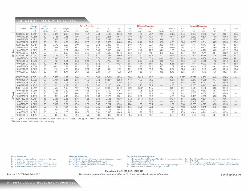
1 0 " S T U D / T R A C K P R O P E R T I E S
MemberDesign
thickness (in)
Yield strength Fy (ksi)
Gross Properties Effective Properties Torsional PropertiesLu (in)Area Weight Ix Sx Rx Iy Ry Ixe Sxe Ma Mad Jx1000 Cw Xo m Ro β(in2) (lb/ft) (in4) (in3) (in) (in4) (in) (in4) (in3) (in-k) (in-k) (in4) (in6) (in) (in) (in)
10" S
tud
1000S162-431 0.0451 33 0.627 2.13 8.03 1.61 3.58 0.168 0.518 7.52 1.30 25.7 22.5 0.425 3.43 -0.823 0.545 3.71 0.951 38.81000S162-54 0.0566 50 0.783 2.66 9.95 1.99 3.57 0.204 0.511 9.39 1.57 47.1 40.4 0.836 4.20 -0.812 0.538 3.69 0.952 31.31000S162-68 0.0713 50 0.978 3.33 12.3 2.47 3.55 0.247 0.502 12.0 2.15 64.5 56.4 1.66 5.12 -0.798 0.531 3.67 0.953 31.01000S162-97 0.1017 50 1.37 4.67 17.0 3.39 3.52 0.320 0.483 17.0 3.27 97.9 92.6 4.73 6.83 -0.768 0.514 3.63 0.955 30.41000S200-431 0.0451 33 0.672 2.29 9.09 1.82 3.68 0.309 0.677 8.60 1.47 29.1 26.2 0.456 6.24 -1.15 0.743 3.91 0.914 49.31000S200-54 0.0566 50 0.839 2.86 11.3 2.26 3.67 0.378 0.671 10.8 1.71 51.1 46.6 0.896 7.67 -1.14 0.737 3.90 0.915 39.81000S200-68 0.0713 50 1.05 3.57 14.0 2.80 3.65 0.460 0.662 13.7 2.42 72.5 64.5 1.78 9.40 -1.12 0.729 3.88 0.917 39.61000S200-97 0.1017 50 1.47 5.02 19.3 3.87 3.62 0.610 0.643 19.3 3.74 112 105 5.08 12.7 -1.09 0.711 3.84 0.920 39.01000S250-431 0.0451 33 0.717 2.44 10.2 2.04 3.77 0.531 0.860 10.2 1.62 31.9 27.7 0.486 10.5 -1.52 0.965 4.16 0.867 60.71000S250-54 0.0566 50 0.896 3.05 12.7 2.54 3.76 0.653 0.854 12.7 1.88 56.3 49.2 0.957 12.9 -1.50 0.958 4.14 0.868 49.11000S250-68 0.0713 50 1.12 3.81 15.8 3.15 3.75 0.799 0.844 15.7 2.77 82.9 68.2 1.90 15.9 -1.49 0.950 4.12 0.870 48.81000S250-97 0.1017 50 1.58 5.36 21.8 4.37 3.72 1.07 0.825 21.8 4.18 141* 120 5.43 21.6 -1.45 0.932 4.08 0.873 45.61000S300-54 0.0566 50 0.95 3.24 14.1 2.82 3.84 1.02 1.04 13.4 1.90 57.0 50.7 1.02 19.9 -1.89 1.19 4.41 0.816 58.01000S300-68 0.0713 50 1.19 4.06 17.5 3.50 3.83 1.26 1.03 17.1 2.80 83.9 70.4 2.02 24.6 -1.87 1.18 4.39 0.818 57.81000S300-97 0.1017 50 1.68 5.71 24.3 4.86 3.81 1.70 1.01 24.0 4.50 135 116 5.78 33.6 -1.84 1.16 4.35 0.821 57.4
10" T
rack
1000T125-431 0.0451 33 0.563 1.92 6.63 1.31 3.43 0.0474 0.290 5.89 0.819 16.2 — 0.382 0.973 -0.379 0.259 3.46 0.988 —1000T125-54 0.0566 50 0.707 2.41 8.34 1.63 3.43 0.0587 0.288 7.48 1.06 31.6 — 0.755 1.21 -0.376 0.256 3.47 0.988 —1000T125-68 0.0713 50 0.890 3.03 10.5 2.05 3.44 0.0727 0.286 10.2 1.57 47.1 — 1.51 1.51 -0.372 0.253 3.47 0.989 —1000T125-97 0.1017 50 1.27 4.32 15.1 2.91 3.45 0.100 0.281 15.1 2.75 82.4 — 4.38 2.12 -0.363 0.247 3.48 0.989 —1000T150-431 0.0451 33 0.586 1.99 7.21 1.42 3.51 0.0804 0.370 6.20 0.837 16.5 — 0.397 1.61 -0.513 0.345 3.56 0.979 —1000T150-54 0.0566 50 0.735 2.50 9.06 1.78 3.51 0.100 0.368 7.88 1.08 32.3 — 0.785 2.01 -0.509 0.342 3.57 0.980 —1000T150-68 0.0713 50 0.926 3.15 11.4 2.23 3.52 0.124 0.366 10.8 1.62 48.5 — 1.57 2.52 -0.505 0.339 3.57 0.980 —1000T150-97 0.1017 50 1.32 4.49 16.4 3.17 3.53 0.172 0.361 16.4 2.90 86.9 — 4.55 3.56 -0.495 0.332 3.58 0.981 —1000T200-431 0.0451 33 0.631 2.15 8.36 1.65 3.64 0.183 0.539 6.72 0.861 17.0 — 0.428 3.54 -0.813 0.534 3.77 0.953 —1000T200-54 0.0566 50 0.792 2.69 10.5 2.06 3.65 0.228 0.537 8.56 1.11 33.3 — 0.845 4.43 -0.809 0.531 3.77 0.954 —1000T200-68 0.0713 50 0.997 3.39 13.3 2.59 3.65 0.284 0.534 11.8 1.68 50.4 — 1.69 5.58 -0.803 0.527 3.78 0.955 —1000T200-97 0.1017 50 1.42 4.84 19.1 3.69 3.66 0.397 0.528 18.6 3.08 92.3 — 4.90 7.92 -0.791 0.519 3.79 0.956 —1000T300-54 0.0566 50 0.905 3.08 13.4 2.63 3.85 0.714 0.888 10.8 1.19 35.7 — 0.966 13.3 -1.50 0.947 4.23 0.874 —1000T300-68 0.0713 50 1.14 3.88 17.0 3.32 3.86 0.893 0.885 14.1 1.90 57.0 — 1.93 16.8 -1.49 0.943 4.23 0.876 —1000T300-97 0.1017 50 1.62 5.53 24.4 4.72 3.88 1.26 0.879 21.5 3.59 107 — 5.60 24.0 -1.48 0.934 4.24 0.879 —
1Web-height-to-thickness ratio exceeds 200. Web stiffeners are required at all support points and concentrated loads. *Allowable moment includes cold work of forming.
15 P H Y S I C A L & S T R U C T U R A L P R O P E R T I E S
clarkdietrich.comPub. No. CD-STR-TechGuide 6/17 The technical content of this literature is effective 6/1/17 and supersedes all previous information.Complies with AISI S100-12 • IBC 2015
Gross Properties:Ix = Moment of Inertia of cross-section about the x-axis.Sx = Section Modulus about the x-axis.Rx = Radius of Gyration of cross-section about the x-axis.Iy = Moment of Inertia of cross-section about the y-axis.Ry = Radius of Gyration of cross-section about the y-axis.
Effective Properties:Ixe = Effective Moment of Inertia of cross-section about the x-axis.Sxe = Effective Section Modulus about the x-axis.Ma = Allowable Moment based on local buckling.Mad = Allowable Moment based on distortional buckling,
assuming Kφ=0.
Torsional and Other Properties:J = St. Venant Torsional Constant. The values of J shown in the tables
have been factored by 1000.Cw = Warping Torsion Constant.Xo = Distance from shear center to the centroid along the principal axis.m = Distance from shear center to mid-plane of web.
Ro = Polar Radius of Gyration of cross-section about the shear center.Βeta = 1-(Xo/Ro).2Lu = Critical unbraced length for lateral-torsional buckling. Members
are considered fully braced when unbraced length is less than Lu.
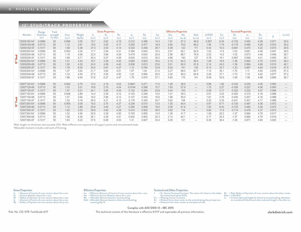
1 2 " S T U D / T R A C K P R O P E R T I E S
MemberDesign
thickness (in)
Yield strength Fy (ksi)
Gross Properties Effective Properties Torsional PropertiesLu (in)Area Weight Ix Sx Rx Iy Ry Ixe Sxe Ma Mad Jx1000 Cw Xo m Ro β(in2) (lb/ft) (in4) (in3) (in) (in4) (in) (in4) (in3) (in-k) (in-k) (in4) (in6) (in) (in) (in)
12" S
tud
1200S162-541 0.0566 50 0.896 3.05 15.7 2.62 4.19 0.212 0.486 14.3 1.91 57.3 46.8 0.957 6.34 -0.732 0.493 4.28 0.971 30.51200S162-68 0.0713 50 1.12 3.81 19.5 3.25 4.17 0.255 0.477 18.4 2.65 79.2 66.2 1.90 7.74 -0.719 0.485 4.26 0.972 30.21200S162-97 0.1017 50 1.58 5.36 27.0 4.50 4.14 0.332 0.459 26.7 4.09 122 111 5.43 10.3 -0.691 0.470 4.22 0.973 29.51200S200-541 0.0566 50 0.953 3.24 17.7 2.94 4.31 0.394 0.643 16.3 2.07 62.1 54.8 1.02 11.6 -1.03 0.681 4.48 0.947 39.01200S200-68 0.0713 50 1.19 4.06 22.0 3.66 4.29 0.479 0.634 20.9 2.96 88.7 76.6 2.02 14.2 -1.02 0.673 4.46 0.948 38.71200S200-97 0.1017 50 1.68 5.71 30.4 5.07 4.26 0.635 0.615 30.2 4.66 140 127 5.78 19.1 -0.987 0.656 4.41 0.950 38.11200S250-541 0.0566 50 1.01 3.43 19.7 3.28 4.42 0.683 0.823 18.4 2.15 64.3 58.4 1.08 19.5 -1.38 0.892 4.70 0.914 48.31200S250-68 0.0713 50 1.26 4.30 24.5 4.08 4.40 0.836 0.813 23.6 3.01 90.0 81.6 2.14 24.0 -1.36 0.884 4.68 0.915 48.11200S250-97 0.1017 50 1.78 6.05 34.0 5.67 4.37 1.12 0.794 33.8 5.04 151 135 6.13 32.7 -1.33 0.867 4.64 0.918 47.51200S300-541 0.0566 50 1.07 3.63 21.7 3.62 4.51 1.07 1.00 21.0 2.27 68.0 60.7 1.14 30.1 -1.74 1.11 4.94 0.876 57.41200S300-68 0.0713 50 1.33 4.54 27.0 4.50 4.50 1.32 0.994 26.5 3.32 99.3 84.8 2.26 37.1 -1.73 1.10 4.92 0.877 57.21200S300-97 0.1017 50 1.88 6.40 37.6 6.27 4.47 1.79 0.975 37.1 5.83 175 141 6.48 50.9 -1.69 1.08 4.88 0.880 56.7
12" T
rack
1200T125-541 0.0566 50 0.820 2.79 13.3 2.19 4.03 0.0601 0.271 11.5 1.29 38.5 — 0.88 1.82 -0.333 0.230 4.06 0.993 —1200T125-68 0.0713 50 1.03 3.51 16.8 2.75 4.04 0.0744 0.268 15.7 1.93 57.9 — 1.75 2.27 -0.329 0.227 4.06 0.993 —1200T125-97 0.1017 50 1.47 5.01 24.1 3.90 4.04 0.102 0.264 23.8 3.44 103 — 5.08 3.17 -0.322 0.222 4.07 0.994 —1200T150-541 0.0566 50 0.848 2.89 14.4 2.36 4.12 0.103 0.348 12.0 1.31 39.3 — 0.91 3.03 -0.454 0.310 4.16 0.988 —1200T150-68 0.0713 50 1.07 3.64 18.2 2.96 4.12 0.127 0.345 16.6 1.99 59.5 — 1.81 3.79 -0.450 0.307 4.16 0.988 —1200T150-97 0.1017 50 1.52 5.18 26.0 4.21 4.13 0.176 0.340 25.7 3.62 108 — 5.25 5.33 -0.441 0.301 4.17 0.989 —1200T200-541 0.0566 50 0.905 3.08 16.5 2.70 4.27 0.236 0.510 13.0 1.35 40.4 — 0.97 6.71 -0.730 0.487 4.36 0.972 —1200T200-68 0.0713 50 1.14 3.88 20.8 3.40 4.27 0.294 0.508 18.0 2.06 61.6 — 1.93 8.43 -0.725 0.483 4.36 0.972 —1200T200-97 0.1017 50 1.62 5.53 29.8 4.83 4.28 0.410 0.502 29.0 3.82 114 — 5.60 11.9 -0.714 0.476 4.37 0.973 —1200T300-541 0.0566 50 1.02 3.46 20.6 3.38 4.50 0.745 0.855 14.5 1.39 41.7 — 1.09 20.2 -1.37 0.884 4.79 0.917 —1200T300-68 0.0713 50 1.28 4.36 26.1 4.26 4.51 0.932 0.852 20.3 2.14 64.1 — 2.17 25.5 -1.37 0.880 4.79 0.918 —1200T300-97 0.1017 50 1.83 6.22 37.5 6.06 4.53 1.31 0.847 33.4 4.05 121 — 6.30 36.4 -1.36 0.871 4.80 0.920 —
1Web-height-to-thickness ratio exceeds 200. Web stiffeners are required at all support points and concentrated loads. *Allowable moment includes cold work of forming.
16 P H Y S I C A L & S T R U C T U R A L P R O P E R T I E S
clarkdietrich.comThe technical content of this literature is effective 6/1/17 and supersedes all previous information.
Gross Properties:Ix = Moment of Inertia of cross-section about the x-axis.Sx = Section Modulus about the x-axis.Rx = Radius of Gyration of cross-section about the x-axis.Iy = Moment of Inertia of cross-section about the y-axis.Ry = Radius of Gyration of cross-section about the y-axis.
Effective Properties:Ixe = Effective Moment of Inertia of cross-section about the x-axis.Sxe = Effective Section Modulus about the x-axis.Ma = Allowable Moment based on local buckling.Mad = Allowable Moment based on distortional buckling,
assuming Kφ=0.
Torsional and Other Properties:J = St. Venant Torsional Constant. The values of J shown in the tables
have been factored by 1000.Cw = Warping Torsion Constant.Xo = Distance from shear center to the centroid along the principal axis.m = Distance from shear center to mid-plane of web.
Ro = Polar Radius of Gyration of cross-section about the shear center.Βeta = 1-(Xo/Ro).2Lu = Critical unbraced length for lateral-torsional buckling. Members
are considered fully braced when unbraced length is less than Lu.
Pub. No. CD-STR-TechGuide 6/17Complies with AISI S100-12 • IBC 2015
1 4 " S T U D / T R A C K P R O P E R T I E S
MemberDesign
thickness (in)
Yield strength Fy (ksi)
Gross Properties Effective Properties Torsional PropertiesLu
(in)Area Weight Ix Sx Rx Iy Ry Ixe Sxe Ma Mad Jx1000 Cw Xo m Ro β(in2) (lb/ft) (in4) (in3) (in) (in4) (in) (in4) (in3) (in-k) (in-k) (in4) (in6) (in) (in) (in)
14" S
tud
1400S162-541 0.0566 50 1.01 3.43 23.3 3.33 4.81 0.218 0.464 20.4 2.26 67.5 52.2 1.08 8.98 -0.667 0.454 4.87 0.981 29.71400S162-68 0.0713 50 1.26 4.30 29.0 4.14 4.79 0.262 0.456 26.4 3.13 93.9 74.6 2.14 11.0 -0.654 0.447 4.85 0.982 29.41400S162-97 0.1017 50 1.78 6.05 40.1 5.73 4.75 0.341 0.438 38.9 4.91 147 128 6.13 14.7 -0.628 0.433 4.81 0.983 28.71400S200-541 0.0566 50 1.07 3.63 26.0 3.71 4.94 0.406 0.617 23.2 2.44 73.1 61.7 1.14 16.4 -0.946 0.633 5.06 0.965 38.21400S200-68 0.0713 50 1.33 4.54 32.3 4.61 4.92 0.494 0.608 29.8 3.50 105 87.2 2.26 20.1 -0.932 0.625 5.04 0.966 37.91400S200-97 0.1017 50 1.88 6.40 44.9 6.41 4.88 0.655 0.590 43.6 5.58 167 147 6.48 27.2 -0.904 0.609 5.00 0.967 37.31400S250-541 0.0566 50 1.12 3.82 28.7 4.10 5.06 0.707 0.794 26.1 2.53 75.7 66.6 1.20 27.7 -1.27 0.835 5.28 0.942 47.61400S250-68 0.0713 50 1.41 4.78 35.8 5.11 5.04 0.865 0.784 33.6 3.55 106 93.8 2.38 34.1 -1.26 0.827 5.26 0.943 47.31400S250-97 0.1017 50 1.98 6.75 49.8 7.11 5.01 1.16 0.765 48.7 6.01 180 158 6.84 46.5 -1.23 0.811 5.22 0.945 46.71400S300-541 0.0566 50 1.18 4.01 31.5 4.49 5.17 1.11 0.972 27.2 2.58 77.3 69.9 1.26 42.7 -1.62 1.05 5.50 0.914 56.81400S300-68 0.0713 50 1.48 5.03 39.2 5.60 5.15 1.37 0.963 36.3 3.66 109 98.3 2.50 52.8 -1.60 1.04 5.48 0.915 56.51400S300-97 0.1017 50 2.08 7.09 54.7 7.81 5.12 1.85 0.943 53.2 6.37 191 166 7.19 72.4 -1.57 1.02 5.44 0.917 55.9
14" T
rack
1400T125-541 0.0566 50 0.933 3.18 20.0 2.82 4.63 0.0611 0.256 16.4 1.52 45.4 — 1.00 2.56 -0.299 0.209 4.64 1.00 —1400T125-68 0.0713 50 1.18 4.00 25.2 3.54 4.63 0.0757 0.254 22.6 2.29 68.6 — 1.99 3.19 -0.296 0.206 4.65 1.00 —1400T125-97 0.1017 50 1.68 5.70 36.0 5.02 4.64 0.104 0.249 34.6 4.13 124 — 5.78 4.44 -0.289 0.201 4.65 1.00 —1400T150-541 0.0566 50 0.962 3.27 21.4 3.01 4.72 0.105 0.330 17.2 1.55 46.3 — 1.03 4.28 -0.410 0.283 4.75 0.993 —1400T150-68 0.0713 50 1.21 4.12 27.0 3.79 4.72 0.130 0.328 23.8 2.35 70.4 — 2.05 5.35 -0.407 0.280 4.75 0.993 —1400T150-97 0.1017 50 1.73 5.88 38.6 5.38 4.73 0.180 0.323 37.3 4.33 130 — 5.95 7.50 -0.399 0.275 4.76 0.993 —1400T200-541 0.0566 50 1.02 3.46 24.2 3.41 4.88 0.242 0.487 18.4 1.59 47.6 — 1.09 9.52 -0.665 0.449 4.95 0.982 —1400T200-68 0.0713 50 1.28 4.36 30.6 4.29 4.88 0.301 0.485 25.7 2.43 72.8 — 2.17 11.9 -0.661 0.446 4.95 0.982 —1400T200-97 0.1017 50 1.83 6.22 43.8 6.10 4.89 0.420 0.479 41.8 4.56 136 — 6.30 16.9 -0.651 0.439 4.96 0.983 —1400T300-541 0.0566 50 1.13 3.85 29.9 4.21 5.14 0.769 0.825 20.3 1.64 49.0 — 1.21 28.8 -1.27 0.829 5.36 0.944 —1400T300-68 0.0713 50 1.42 4.85 37.7 5.30 5.15 0.962 0.822 28.8 2.52 75.5 — 2.41 36.3 -1.26 0.825 5.36 0.944 —1400T300-97 0.1017 50 2.03 6.91 54.1 7.54 5.16 1.35 0.816 47.6 4.82 144 — 7.00 51.6 -1.25 0.817 5.37 0.946 —
1Web-height-to-thickness ratio exceeds 200. Web stiffeners are required at all support points and concentrated loads. *Allowable moment includes cold work of forming.
17 S T U D S H E A R & T R A C K S H E A R
clarkdietrich.comThe technical content of this literature is effective 6/1/17 and supersedes all previous information.
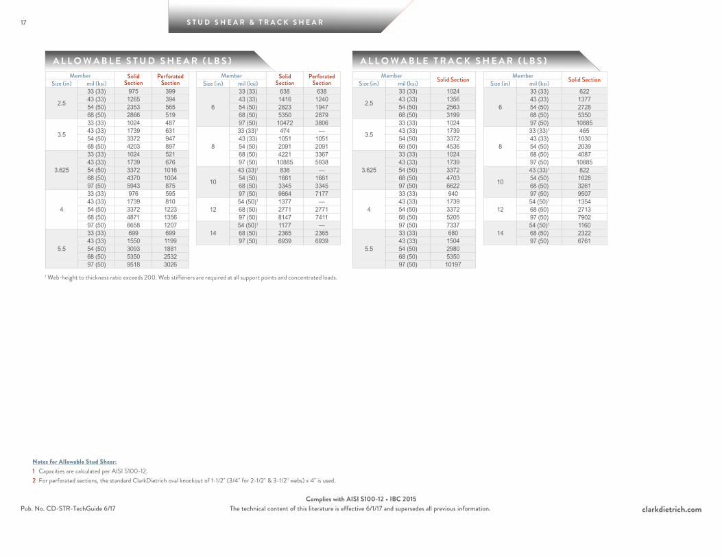
Notes for Allowable Stud Shear:1 Capacities are calculated per AISI S100-12.2 For perforated sections, the standard ClarkDietrich oval knockout of 1-1/2" (3/4" for 2-1/2" & 3-1/2" webs) x 4" is used.
Pub. No. CD-STR-TechGuide 6/17Complies with AISI S100-12 • IBC 2015
A L L O W A B L E S T U D S H E A R ( L B S ) A L L O W A B L E T R A C K S H E A R ( L B S )Member Solid
SectionPerforated
SectionSize (in) mil (ksi)
2.5
33 (33) 975 39943 (33) 1265 39454 (50) 2353 56568 (50) 2866 519
3.5
33 (33) 1024 48743 (33) 1739 63154 (50) 3372 94768 (50) 4203 897
3.625
33 (33) 1024 52143 (33) 1739 67654 (50) 3372 101668 (50) 4370 100497 (50) 5943 875
4
33 (33) 976 59543 (33) 1739 81054 (50) 3372 122368 (50) 4871 135697 (50) 6658 1207
5.5
33 (33) 699 69943 (33) 1550 119954 (50) 3093 188168 (50) 5350 253297 (50) 9518 3026
Member Solid SectionSize (in) mil (ksi)
2.5
33 (33) 102443 (33) 135654 (50) 256368 (50) 3199
3.5
33 (33) 102443 (33) 173954 (50) 337268 (50) 4536
3.625
33 (33) 102443 (33) 173954 (50) 337268 (50) 470397 (50) 6622
4
33 (33) 94043 (33) 173954 (50) 337268 (50) 520597 (50) 7337
5.5
33 (33) 68043 (33) 150454 (50) 298068 (50) 535097 (50) 10197
1 Web-height to thickness ratio exceeds 200. Web stiffeners are required at all support points and concentrated loads.
Member Solid Section
Perforated SectionSize (in) mil (ksi)
6
33 (33) 638 63843 (33) 1416 124054 (50) 2823 194768 (50) 5350 287997 (50) 10472 3806
8
33 (33)1 474 —43 (33) 1051 105154 (50) 2091 209168 (50) 4221 336797 (50) 10885 5938
10
43 (33)1 836 —54 (50) 1661 166168 (50) 3345 334597 (50) 9864 7177
1254 (50)1 1377 —68 (50) 2771 277197 (50) 8147 7411
1454 (50)1 1177 —68 (50) 2365 236597 (50) 6939 6939
Member Solid SectionSize (in) mil (ksi)
6
33 (33) 62243 (33) 137754 (50) 272868 (50) 535097 (50) 10885
8
33 (33)1 46543 (33) 103054 (50) 203968 (50) 408797 (50) 10885
10
43 (33)1 82254 (50) 162868 (50) 326197 (50) 9507
1254 (50)1 135468 (50) 271397 (50) 7902
1454 (50)1 116068 (50) 232297 (50) 6761
A L L O W A B L E W A L L H E I G H T T A B L E S
18
I N T E R I O R W A L L H E I G H T S
19 A L L O W A B L E W A L L H E I G H T S
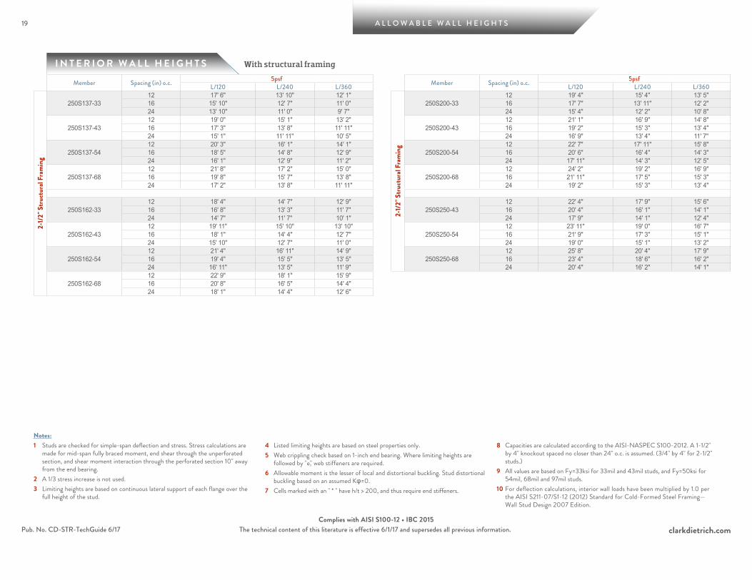
With structural framing
clarkdietrich.comThe technical content of this literature is effective 6/1/17 and supersedes all previous information.
Notes:1 Studs are checked for simple-span deflection and stress. Stress calculations are
made for mid-span fully braced moment, end shear through the unperforated section, and shear moment interaction through the perforated section 10" away from the end bearing.
2 A 1/3 stress increase is not used.3 Limiting heights are based on continuous lateral support of each flange over the
full height of the stud.
4 Listed limiting heights are based on steel properties only.5 Web crippling check based on 1-inch end bearing. Where limiting heights are
followed by "e," web stiffeners are required.6 Allowable moment is the lesser of local and distortional buckling. Stud distortional
buckling based on an assumed Kφ=0.7 Cells marked with an " * " have h/t > 200, and thus require end stiffeners.
8 Capacities are calculated according to the AISI-NASPEC S100-2012. A 1-1/2" by 4" knockout spaced no closer than 24" o.c. is assumed. (3/4" by 4" for 2-1/2" studs.)
9 All values are based on Fy=33ksi for 33mil and 43mil studs, and Fy=50ksi for 54mil, 68mil and 97mil studs.
10 For deflection calculations, interior wall loads have been multiplied by 1.0 per the AISI S211-07/S1-12 (2012) Standard for Cold-Formed Steel Framing—Wall Stud Design 2007 Edition.
Pub. No. CD-STR-TechGuide 6/17Complies with AISI S100-12 • IBC 2015
Member Spacing (in) o.c. 5psfL/120 L/240 L/360
2-1/
2" S
truct
ural
Fram
ing
250S137-3312 17' 6" 13' 10" 12' 1" 16 15' 10" 12' 7" 11' 0" 24 13' 10" 11' 0" 9' 7"
250S137-4312 19' 0" 15' 1" 13' 2" 16 17' 3" 13' 8" 11' 11" 24 15' 1" 11' 11" 10' 5"
250S137-5412 20' 3" 16' 1" 14' 1" 16 18' 5" 14' 8" 12' 9" 24 16' 1" 12' 9" 11' 2"
250S137-6812 21' 8" 17' 2" 15' 0" 16 19' 8" 15' 7" 13' 8" 24 17' 2" 13' 8" 11' 11"
250S162-3312 18' 4" 14' 7" 12' 9" 16 16' 8" 13' 3" 11' 7" 24 14' 7" 11' 7" 10' 1"
250S162-4312 19' 11" 15' 10" 13' 10" 16 18' 1" 14' 4" 12' 7" 24 15' 10" 12' 7" 11' 0"
250S162-5412 21' 4" 16' 11" 14' 9" 16 19' 4" 15' 5" 13' 5" 24 16' 11" 13' 5" 11' 9"
250S162-6812 22' 9" 18' 1" 15' 9" 16 20' 8" 16' 5" 14' 4" 24 18' 1" 14' 4" 12' 6"
Member Spacing (in) o.c. 5psfL/120 L/240 L/360
2-1/
2" S
truct
ural
Fram
ing
250S200-3312 19' 4" 15' 4" 13' 5" 16 17' 7" 13' 11" 12' 2" 24 15' 4" 12' 2" 10' 8"
250S200-4312 21' 1" 16' 9" 14' 8" 16 19' 2" 15' 3" 13' 4" 24 16' 9" 13' 4" 11' 7"
250S200-5412 22' 7" 17' 11" 15' 8" 16 20' 6" 16' 4" 14' 3" 24 17' 11" 14' 3" 12' 5"
250S200-6812 24' 2" 19' 2" 16' 9" 16 21' 11" 17' 5" 15' 3" 24 19' 2" 15' 3" 13' 4"
250S250-4312 22' 4" 17' 9" 15' 6" 16 20' 4" 16' 1" 14' 1" 24 17' 9" 14' 1" 12' 4"
250S250-5412 23' 11" 19' 0" 16' 7" 16 21' 9" 17' 3" 15' 1" 24 19' 0" 15' 1" 13' 2"
250S250-6812 25' 8" 20' 4" 17' 9" 16 23' 4" 18' 6" 16' 2" 24 20' 4" 16' 2" 14' 1"
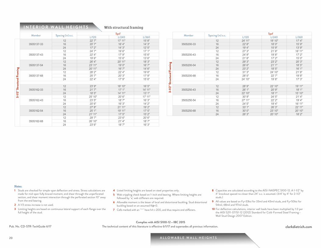
I N T E R I O R W A L L H E I G H T S
A L L O W A B L E W A L L H E I G H T S
With structural framing
clarkdietrich.comThe technical content of this literature is effective 6/1/17 and supersedes all previous information.
20
Notes:1 Studs are checked for simple-span deflection and stress. Stress calculations are
made for mid-span fully braced moment, end shear through the unperforated section, and shear moment interaction through the perforated section 10" away from the end bearing.
2 A 1/3 stress increase is not used.3 Limiting heights are based on continuous lateral support of each flange over the
full height of the stud.
4 Listed limiting heights are based on steel properties only.5 Web crippling check based on 1-inch end bearing. Where limiting heights are
followed by "e," web stiffeners are required.6 Allowable moment is the lesser of local and distortional buckling. Stud distortional
buckling based on an assumed Kφ=0.7 Cells marked with an " * " have h/t > 200, and thus require end stiffeners.
8 Capacities are calculated according to the AISI-NASPEC S100-12. A 1-1/2" by 4" knockout spaced no closer than 24" o.c. is assumed. (3/4" by 4" for 2-1/2" studs.)
9 All values are based on Fy=33ksi for 33mil and 43mil studs, and Fy=50ksi for 54mil, 68mil and 97mil studs.
10 For deflection calculations, interior wall loads have been multiplied by 1.0 per the AISI S211-07/S1-12 (2012) Standard for Cold-Formed Steel Framing—Wall Stud Design 2007 Edition.
Pub. No. CD-STR-TechGuide 6/17Complies with AISI S100-12 • IBC 2015
Member Spacing (in) o.c. 5psfL/120 L/240 L/360
3-1/
2" S
truct
ural
Fram
ing
350S137-3312 22' 7" 17' 11" 15' 8" 16 20' 7" 16' 4" 14' 3" 24 17' 2" 14' 3" 12' 5"
350S137-4312 24' 7" 19' 6" 17' 1" 16 22' 4" 17' 9" 15' 6" 24 19' 6" 15' 6" 13' 6"
350S137-5412 26' 4" 20' 11" 18' 3" 16 23' 11" 19' 0" 16' 7" 24 20' 11" 16' 7" 14' 6"
350S137-6812 28' 2" 22' 4" 19' 6" 16 25' 7" 20' 3" 17' 9" 24 22' 4" 17' 9" 15' 6"
350S162-3312 23' 9" 18' 10" 16' 5" 16 21' 7" 17' 1" 14' 11" 24 18' 5" 14' 11" 13' 1"
350S162-4312 25' 10" 20' 6" 17' 11" 16 23' 5" 18' 7" 16' 3" 24 20' 6" 16' 3" 14' 2"
350S162-5412 27' 8" 21' 11" 19' 2" 16 25' 1" 19' 11" 17' 5" 24 21' 11" 17' 5" 15' 2"
350S162-6812 29' 7" 23' 6" 20' 6" 16 26' 10" 21' 4" 18' 7" 24 23' 6" 18' 7" 16' 3"
Member Spacing (in) o.c. 5psfL/120 L/240 L/360
3-1/
2" S
truct
ural
Fram
ing
350S200-3312 24' 11" 19' 10" 17' 4" 16 22' 8" 18' 0" 15' 9" 24 19' 4" 15' 9" 13' 9"
350S200-4312 27' 3" 21' 8" 18' 11" 16 24' 9" 19' 8" 17' 2" 24 21' 8" 17' 2" 15' 0"
350S200-5412 29' 3" 23' 2" 20' 3" 16 26' 6" 21' 1" 18' 5" 24 23' 2" 18' 5" 16' 1"
350S200-6812 31' 3" 24' 10" 21' 8" 16 28' 5" 22' 7" 19' 8" 24 24' 10" 19' 8" 17' 3"
350S250-4312 28' 9" 22' 10" 19' 11" 16 26' 1" 20' 9" 18' 1" 24 22' 10" 18' 1" 15' 10"
350S250-5412 30' 9" 24' 5" 21' 4" 16 27' 11" 22' 2" 19' 4" 24 24' 5" 19' 4" 16' 11"
350S250-6812 33' 1" 26' 3" 22' 11" 16 30' 0" 23' 10" 20' 10" 24 26' 3" 20' 10" 18' 2"
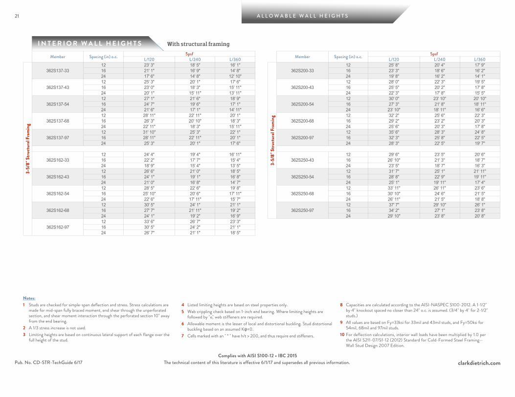
I N T E R I O R W A L L H E I G H T S
21 A L L O W A B L E W A L L H E I G H T S
With structural framing
clarkdietrich.comThe technical content of this literature is effective 6/1/17 and supersedes all previous information.
Notes:1 Studs are checked for simple-span deflection and stress. Stress calculations are
made for mid-span fully braced moment, end shear through the unperforated section, and shear moment interaction through the perforated section 10" away from the end bearing.
2 A 1/3 stress increase is not used.3 Limiting heights are based on continuous lateral support of each flange over the
full height of the stud.
4 Listed limiting heights are based on steel properties only.5 Web crippling check based on 1-inch end bearing. Where limiting heights are
followed by "e," web stiffeners are required.6 Allowable moment is the lesser of local and distortional buckling. Stud distortional
buckling based on an assumed Kφ=0.7 Cells marked with an " * " have h/t > 200, and thus require end stiffeners.
8 Capacities are calculated according to the AISI-NASPEC S100-2012. A 1-1/2" by 4" knockout spaced no closer than 24" o.c. is assumed. (3/4" by 4" for 2-1/2" studs.)
9 All values are based on Fy=33ksi for 33mil and 43mil studs, and Fy=50ksi for 54mil, 68mil and 97mil studs.
10 For deflection calculations, interior wall loads have been multiplied by 1.0 per the AISI S211-07/S1-12 (2012) Standard for Cold-Formed Steel Framing—Wall Stud Design 2007 Edition.
Pub. No. CD-STR-TechGuide 6/17Complies with AISI S100-12 • IBC 2015
Member Spacing (in) o.c. 5psf Member Spacing (in) o.c. 5psfL/120 L/240 L/360 L/120 L/240 L/360
3-5/
8" S
truct
ural
Fram
ing
362S137-3312 23' 3" 18' 5" 16' 1"
3-5/
8" S
truct
ural
Fram
ing
362S200-3312 25' 8" 20' 4" 17' 9"
16 21' 1" 16' 9" 14' 8" 16 23' 3" 18' 6" 16' 2" 24 17' 6" 14' 8" 12' 10" 24 19' 8" 16' 2" 14' 1"
362S137-4312 25' 3" 20' 1" 17' 6"
362S200-4312 28' 0" 22' 3" 19' 5"
16 23' 0" 18' 3" 15' 11" 16 25' 5" 20' 2" 17' 8" 24 20' 1" 15' 11" 13' 11" 24 22' 3" 17' 8" 15' 5"
362S137-5412 27' 1" 21' 6" 18' 9"
362S200-5412 30' 0" 23' 10" 20' 10"
16 24' 7" 19' 6" 17' 1" 16 27' 3" 21' 8" 18' 11" 24 21' 6" 17' 1" 14' 11" 24 23' 10" 18' 11" 16' 6"
362S137-6812 28' 11" 22' 11" 20' 1"
362S200-6812 32' 2" 25' 6" 22' 3"
16 26' 3" 20' 10" 18' 3" 16 29' 2" 23' 2" 20' 3" 24 22' 11" 18' 3" 15' 11" 24 25' 6" 20' 3" 17' 8"
362S137-9712 31' 10" 25' 3" 22' 1"
362S200-9712 35' 6" 28' 3" 24' 8"
16 28' 11" 22' 11" 20' 1" 16 32' 3" 25' 8" 22' 5" 24 25' 3" 20' 1" 17' 6" 24 28' 3" 22' 5" 19' 7"
362S162-3312 24' 4" 19' 4" 16' 11"
362S250-4312 29' 6" 23' 5" 20' 6"
16 22' 2" 17' 7" 15' 4" 16 26' 10" 21' 3" 18' 7" 24 18' 9" 15' 4" 13' 5" 24 23' 5" 18' 7" 16' 3"
362S162-4312 26' 6" 21' 0" 18' 5"
362S250-5412 31' 7" 25' 1" 21' 11"
16 24' 1" 19' 1" 16' 8" 16 28' 8" 22' 9" 19' 11" 24 21' 0" 16' 8" 14' 7" 24 25' 1" 19' 11" 17' 4"
362S162-5412 28' 5" 22' 6" 19' 8"
362S250-6812 33' 11" 26' 11" 23' 6"
16 25' 10" 20' 6" 17' 11" 16 30' 10" 24' 6" 21' 5" 24 22' 6" 17' 11" 15' 7" 24 26' 11" 21' 5" 18' 8"
362S162-6812 30' 5" 24' 1" 21' 1"
362S250-9712 37' 7" 29' 10" 26' 1"
16 27' 7" 21' 11" 19' 2" 16 34' 2" 27' 1" 23' 8" 24 24' 1" 19' 2" 16' 9" 24 29' 10" 23' 8" 20' 8"
362S162-9712 33' 6" 26' 7" 23' 3" 16 30' 5" 24' 2" 21' 1" 24 26' 7" 21' 1" 18' 5"
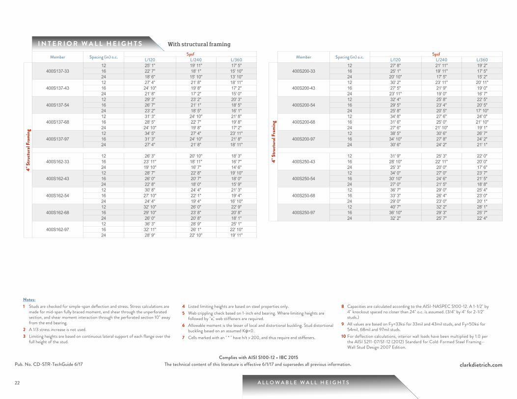
I N T E R I O R W A L L H E I G H T S
A L L O W A B L E W A L L H E I G H T S
With structural framing
clarkdietrich.comThe technical content of this literature is effective 6/1/17 and supersedes all previous information.
22
Notes:1 Studs are checked for simple-span deflection and stress. Stress calculations are
made for mid-span fully braced moment, end shear through the unperforated section, and shear moment interaction through the perforated section 10" away from the end bearing.
2 A 1/3 stress increase is not used.3 Limiting heights are based on continuous lateral support of each flange over the
full height of the stud.
4 Listed limiting heights are based on steel properties only.5 Web crippling check based on 1-inch end bearing. Where limiting heights are
followed by "e," web stiffeners are required.6 Allowable moment is the lesser of local and distortional buckling. Stud distortional
buckling based on an assumed Kφ=0.7 Cells marked with an " * " have h/t > 200, and thus require end stiffeners.
8 Capacities are calculated according to the AISI-NASPEC S100-12. A 1-1/2" by 4" knockout spaced no closer than 24" o.c. is assumed. (3/4" by 4" for 2-1/2" studs.)
9 All values are based on Fy=33ksi for 33mil and 43mil studs, and Fy=50ksi for 54mil, 68mil and 97mil studs.
10 For deflection calculations, interior wall loads have been multiplied by 1.0 per the AISI S211-07/S1-12 (2012) Standard for Cold-Formed Steel Framing—Wall Stud Design 2007 Edition.
Pub. No. CD-STR-TechGuide 6/17Complies with AISI S100-12 • IBC 2015
Member Spacing (in) o.c. 5psf Member Spacing (in) o.c. 5psfL/120 L/240 L/360 L/120 L/240 L/360
4" S
truct
ural
Fram
ing
400S137-3312 25' 1" 19' 11" 17' 5"
4" S
truct
ural
Fram
ing
400S200-3312 27' 8" 21' 11" 19' 2"
16 22' 7" 18' 1" 15' 10" 16 25' 1" 19' 11" 17' 5" 24 18' 6" 15' 10" 13' 10" 24 20' 10" 17' 5" 15' 2"
400S137-4312 27' 4" 21' 8" 18' 11"
400S200-4312 30' 2" 23' 11" 20' 11"
16 24' 10" 19' 8" 17' 2" 16 27' 5" 21' 9" 19' 0" 24 21' 8" 17' 2" 15' 0" 24 23' 11" 19' 0" 16' 7"
400S137-5412 29' 3" 23' 2" 20' 3"
400S200-5412 32' 4" 25' 8" 22' 5"
16 26' 7" 21' 1" 18' 5" 16 29' 5" 23' 4" 20' 5" 24 23' 2" 18' 5" 16' 1" 24 25' 8" 20' 5" 17' 10"
400S137-6812 31' 3" 24' 10" 21' 8"
400S200-6812 34' 8" 27' 6" 24' 0"
16 28' 5" 22' 7" 19' 8" 16 31' 6" 25' 0" 21' 10" 24 24' 10" 19' 8" 17' 2" 24 27' 6" 21' 10" 19' 1"
400S137-9712 34' 5" 27' 4" 23' 11"
400S200-9712 38' 5" 30' 6" 26' 7"
16 31' 3" 24' 10" 21' 8" 16 34' 10" 27' 8" 24' 2" 24 27' 4" 21' 8" 18' 11" 24 30' 6" 24' 2" 21' 1"
400S162-3312 26' 3" 20' 10" 18' 3"
400S250-4312 31' 9" 25' 3" 22' 0"
16 23' 11" 18' 11" 16' 7" 16 28' 10" 22' 11" 20' 0" 24 19' 10" 16' 7" 14' 6" 24 25' 3" 20' 0" 17' 6"
400S162-4312 28' 7" 22' 8" 19' 10"
400S250-5412 34' 0" 27' 0" 23' 7"
16 26' 0" 20' 7" 18' 0" 16 30' 10" 24' 6" 21' 5" 24 22' 8" 18' 0" 15' 9" 24 27' 0" 21' 5" 18' 8"
400S162-5412 30' 8" 24' 4" 21' 3"
400S250-6812 36' 7" 29' 0" 25' 4"
16 27' 10" 22' 1" 19' 4" 16 33' 3" 26' 4" 23' 0" 24 24' 4" 19' 4" 16' 10" 24 29' 0" 23' 0" 20' 1"
400S162-6812 32' 10" 26' 0" 22' 9"
400S250-9712 40' 7" 32' 2" 28' 1"
16 29' 10" 23' 8" 20' 8" 16 36' 10" 29' 3" 25' 7" 24 26' 0" 20' 8" 18' 1" 24 32' 2" 25' 7" 22' 4"
400S162-9712 36' 3" 28' 9" 25' 1" 16 32' 11" 26' 1" 22' 10" 24 28' 9" 22' 10" 19' 11"
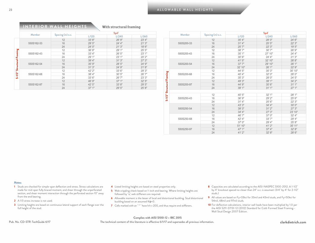
I N T E R I O R W A L L H E I G H T S
23 A L L O W A B L E W A L L H E I G H T S
With structural framing
clarkdietrich.comThe technical content of this literature is effective 6/1/17 and supersedes all previous information.
Notes:1 Studs are checked for simple-span deflection and stress. Stress calculations are
made for mid-span fully braced moment, end shear through the unperforated section, and shear moment interaction through the perforated section 10" away from the end bearing.
2 A 1/3 stress increase is not used.3 Limiting heights are based on continuous lateral support of each flange over the
full height of the stud.
4 Listed limiting heights are based on steel properties only.5 Web crippling check based on 1-inch end bearing. Where limiting heights are
followed by "e," web stiffeners are required.6 Allowable moment is the lesser of local and distortional buckling. Stud distortional
buckling based on an assumed Kφ=0.7 Cells marked with an " * " have h/t > 200, and thus require end stiffeners.
8 Capacities are calculated according to the AISI-NASPEC S100-2012. A 1-1/2" by 4" knockout spaced no closer than 24" o.c. is assumed. (3/4" by 4" for 2-1/2" studs.)
9 All values are based on Fy=33ksi for 33mil and 43mil studs, and Fy=50ksi for 54mil, 68mil and 97mil studs.
10 For deflection calculations, interior wall loads have been multiplied by 1.0 per the AISI S211-07/S1-12 (2012) Standard for Cold-Formed Steel Framing—Wall Stud Design 2007 Edition.
Pub. No. CD-STR-TechGuide 6/17Complies with AISI S100-12 • IBC 2015
Member Spacing (in) o.c. 5psfL/120 L/240 L/360
5-1/
2" S
truct
ural
Fram
ing
550S162-3312 33' 8" 26' 9" 23' 4" 16 29' 5" 24' 4" 21' 3" 24 24' 0" 21' 3" 18' 6"
550S162-4312 36' 8" 29' 1" 25' 5" 16 33' 4" 26' 5" 23' 1" 24 29' 1" 23' 1" 20' 2"
550S162-5412 39' 4" 31' 3" 27' 3" 16 35' 9" 28' 5" 24' 9" 24 31' 3" 24' 9" 21' 8"
550S162-6812 42' 2" 33' 6" 29' 3" 16 38' 4" 30' 5" 26' 7" 24 33' 6" 26' 7" 23' 3"
550S162-9712 46' 9" 37' 1" 32' 5" 16 42' 5" 33' 8" 29' 5" 24 37' 1" 29' 5" 25' 8"
Member Spacing (in) o.c. 5psfL/120 L/240 L/360
5-1/
2" S
truct
ural
Fram
ing
550S200-3312 35' 4" 28' 0" 24' 6" 16 31' 4" 25' 5" 22' 3" 24 25' 7" 22' 3" 19' 5"
550S200-4312 38' 7" 30' 7" 26' 9" 16 35' 1" 27' 10" 24' 4" 24 30' 6" 24' 4" 21' 3"
550S200-5412 41' 5" 32' 10" 28' 8" 16 37' 7" 29' 10" 26' 1" 24 32' 10" 26' 1" 22' 9"
550S200-6812 44' 5" 35' 3" 30' 10" 16 40' 4" 32' 0" 28' 0" 24 35' 3" 28' 0" 24' 5"
550S200-9712 49' 3" 39' 1" 34' 2" 16 44' 9" 35' 6" 31' 1" 24 39' 1" 31' 1" 27' 1"
550S250-4312 40' 5" 32' 1" 28' 1" 16 36' 9" 29' 2" 25' 6" 24 31' 4" 25' 6" 22' 3"
550S250-5412 43' 3" 34' 4" 30' 0" 16 39' 3" 31' 2" 27' 3" 24 34' 4" 27' 3" 23' 10"
550S250-6812 46' 7" 37' 0" 32' 4" 16 42' 4" 33' 7" 29' 4" 24 37' 0" 29' 4" 25' 8"
550S250-9712 51' 10" 41' 2" 35' 11" 16 47' 1" 37' 4" 32' 8" 24 41' 2" 32' 8" 28' 6"
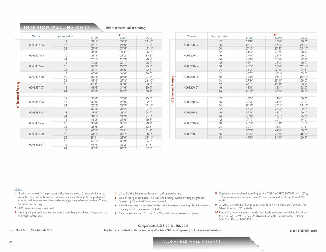
I N T E R I O R W A L L H E I G H T S
A L L O W A B L E W A L L H E I G H T S
With structural framing
clarkdietrich.comThe technical content of this literature is effective 6/1/17 and supersedes all previous information.
24
Notes:1 Studs are checked for simple-span deflection and stress. Stress calculations are
made for mid-span fully braced moment, end shear through the unperforated section, and shear moment interaction through the perforated section 10" away from the end bearing.
2 A 1/3 stress increase is not used.3 Limiting heights are based on continuous lateral support of each flange over the
full height of the stud.
4 Listed limiting heights are based on steel properties only.5 Web crippling check based on 1-inch end bearing. Where limiting heights are
followed by "e," web stiffeners are required.6 Allowable moment is the lesser of local and distortional buckling. Stud distortional
buckling based on an assumed Kφ=0.7 Cells marked with an " * " have h/t > 200, and thus require end stiffeners.
8 Capacities are calculated according to the AISI-NASPEC S100-12. A 1-1/2" by 4" knockout spaced no closer than 24" o.c. is assumed. (3/4" by 4" for 2-1/2" studs.)
9 All values are based on Fy=33ksi for 33mil and 43mil studs, and Fy=50ksi for 54mil, 68mil and 97mil studs.
10 For deflection calculations, interior wall loads have been multiplied by 1.0 per the AISI S211-07/S1-12 (2012) Standard for Cold-Formed Steel Framing—Wall Stud Design 2007 Edition.
Pub. No. CD-STR-TechGuide 6/17Complies with AISI S100-12 • IBC 2015
Member Spacing (in) o.c. 5psf Member Spacing (in) o.c. 5psfL/120 L/240 L/360 L/120 L/240 L/360
6" S
truct
ural
Fram
ing
600S137-3312 33' 1" 27' 3" 23' 10"
6" S
truct
ural
Fram
ing
600S200-3312 37' 9" 30' 0" 26' 2"
16 28' 7" 24' 9" 21' 8" 16 32' 10" 27' 3" 23' 10" 24 23' 4" 21' 8" 18' 11" 24 26' 10" 23' 10" 20' 10"
600S137-4312 37' 8" 29' 11" 26' 2"
600S200-4312 41' 3" 32' 9" 28' 7"
16 34' 3" 27' 2" 23' 9" 16 37' 6" 29' 9" 26' 0" 24 28' 1" 23' 9" 20' 9" 24 32' 0" 26' 0" 22' 9"
600S137-5412 40' 5" 32' 1" 28' 0"
600S200-5412 44' 4" 35' 2" 30' 9"
16 36' 9" 29' 2" 25' 6" 16 40' 3" 32' 0" 27' 11" 24 32' 1" 25' 6" 22' 3" 24 35' 2" 27' 11" 24' 5"
600S137-6812 43' 4" 34' 4" 30' 0"
600S200-6812 47' 7" 37' 9" 33' 0"
16 39' 4" 31' 3" 27' 3" 16 43' 2" 34' 4" 29' 11" 24 34' 4" 27' 3" 23' 10" 24 37' 9" 29' 11" 26' 2"
600S137-9712 47' 11" 38' 0" 33' 2"
600S200-9712 52' 10" 41' 11" 36' 7"
16 43' 6" 34' 6" 30' 2" 16 48' 0" 38' 1" 33' 3" 24 38' 0" 30' 2" 26' 4" 24 41' 11" 33' 3" 29' 1"
600S162-3312 35' 6" 28' 8" 25' 0"
600S250-4312 43' 3" 34' 4" 30' 0"
16 30' 9" 26' 0" 22' 9" 16 39' 3" 31' 2" 27' 3" 24 25' 2" 22' 9" 19' 10" 24 32' 11" 27' 3" 23' 10"
600S162-4312 39' 4" 31' 2" 27' 3"
600S250-5412 46' 3" 36' 8" 32' 1"
16 35' 9" 28' 4" 24' 9" 16 42' 0" 33' 4" 29' 1" 24 31' 1" 24' 9" 21' 8" 24 36' 8" 29' 1" 25' 5"
600S162-5412 42' 2" 33' 6" 29' 3"
600S250-6812 49' 10" 39' 7" 34' 7"
16 38' 4" 30' 5" 26' 7" 16 45' 3" 35' 11" 31' 5" 24 33' 6" 26' 7" 23' 3" 24 39' 7" 31' 5" 27' 5"
600S162-6812 45' 3" 35' 11" 31' 4"
600S250-9712 55' 5" 44' 0" 38' 5"
16 41' 1" 32' 7" 28' 6" 16 50' 4" 40' 0" 34' 11" 24 35' 11" 28' 6" 24' 11" 24 44' 0" 34' 11" 30' 6"
600S162-9712 50' 1" 39' 9" 34' 9" 16 45' 6" 36' 2" 31' 7" 24 39' 9" 31' 7" 27' 7"
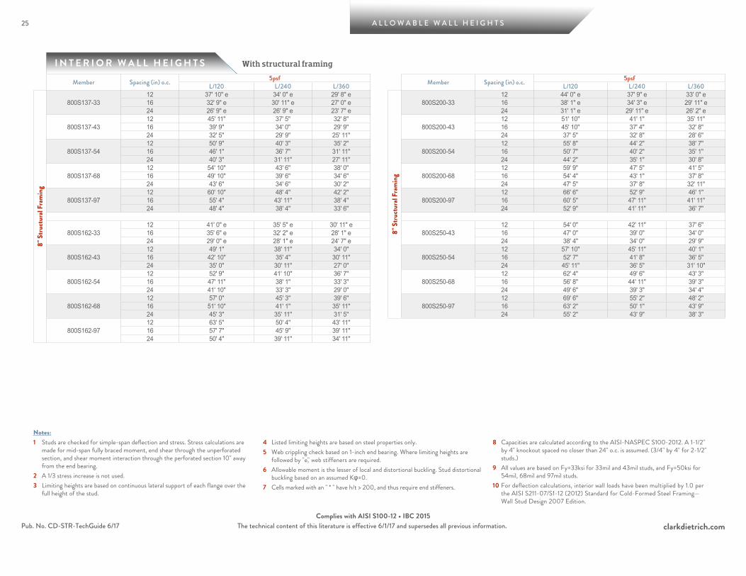
I N T E R I O R W A L L H E I G H T S
25 A L L O W A B L E W A L L H E I G H T S
With structural framing
clarkdietrich.comThe technical content of this literature is effective 6/1/17 and supersedes all previous information.
Notes:1 Studs are checked for simple-span deflection and stress. Stress calculations are
made for mid-span fully braced moment, end shear through the unperforated section, and shear moment interaction through the perforated section 10" away from the end bearing.
2 A 1/3 stress increase is not used.3 Limiting heights are based on continuous lateral support of each flange over the
full height of the stud.
4 Listed limiting heights are based on steel properties only.5 Web crippling check based on 1-inch end bearing. Where limiting heights are
followed by "e," web stiffeners are required.6 Allowable moment is the lesser of local and distortional buckling. Stud distortional
buckling based on an assumed Kφ=0.7 Cells marked with an " * " have h/t > 200, and thus require end stiffeners.
8 Capacities are calculated according to the AISI-NASPEC S100-2012. A 1-1/2" by 4" knockout spaced no closer than 24" o.c. is assumed. (3/4" by 4" for 2-1/2" studs.)
9 All values are based on Fy=33ksi for 33mil and 43mil studs, and Fy=50ksi for 54mil, 68mil and 97mil studs.
10 For deflection calculations, interior wall loads have been multiplied by 1.0 per the AISI S211-07/S1-12 (2012) Standard for Cold-Formed Steel Framing—Wall Stud Design 2007 Edition.
Pub. No. CD-STR-TechGuide 6/17Complies with AISI S100-12 • IBC 2015
Member Spacing (in) o.c. 5psf Member Spacing (in) o.c. 5psfL/120 L/240 L/360 L/120 L/240 L/360
8" S
truct
ural
Fram
ing
800S137-3312 37' 10" e 34' 0" e 29' 8" e
8" S
truct
ural
Fram
ing
800S200-3312 44' 0" e 37' 9" e 33' 0" e
16 32' 9" e 30' 11" e 27' 0" e 16 38' 1" e 34' 3" e 29' 11" e 24 26' 9" e 26' 9" e 23' 7" e 24 31' 1" e 29' 11" e 26' 2" e
800S137-4312 45' 11" 37' 5" 32' 8"
800S200-4312 51' 10" 41' 1" 35' 11"
16 39' 9" 34' 0" 29' 9" 16 45' 10" 37' 4" 32' 8" 24 32' 5" 29' 9" 25' 11" 24 37' 5" 32' 8" 28' 6"
800S137-5412 50' 9" 40' 3" 35' 2"
800S200-5412 55' 8" 44' 2" 38' 7"
16 46' 1" 36' 7" 31' 11" 16 50' 7" 40' 2" 35' 1" 24 40' 3" 31' 11" 27' 11" 24 44' 2" 35' 1" 30' 8"
800S137-6812 54' 10" 43' 6" 38' 0"
800S200-6812 59' 9" 47' 5" 41' 5"
16 49' 10" 39' 6" 34' 6" 16 54' 4" 43' 1" 37' 8" 24 43' 6" 34' 6" 30' 2" 24 47' 5" 37' 8" 32' 11"
800S137-9712 60' 10" 48' 4" 42' 2"
800S200-9712 66' 6" 52' 9" 46' 1"
16 55' 4" 43' 11" 38' 4" 16 60' 5" 47' 11" 41' 11" 24 48' 4" 38' 4" 33' 6" 24 52' 9" 41' 11" 36' 7"
800S162-3312 41' 0" e 35' 5" e 30' 11" e
800S250-4312 54' 0" 42' 11" 37' 6"
16 35' 6" e 32' 2" e 28' 1" e 16 47' 0" 39' 0" 34' 0" 24 29' 0" e 28' 1" e 24' 7" e 24 38' 4" 34' 0" 29' 9"
800S162-4312 49' 1" 38' 11" 34' 0"
800S250-5412 57' 10" 45' 11" 40' 1"
16 42' 10" 35' 4" 30' 11" 16 52' 7" 41' 8" 36' 5" 24 35' 0" 30' 11" 27' 0" 24 45' 11" 36' 5" 31' 10"
800S162-5412 52' 9" 41' 10" 36' 7"
800S250-6812 62' 4" 49' 6" 43' 3"
16 47' 11" 38' 1" 33' 3" 16 56' 8" 44' 11" 39' 3" 24 41' 10" 33' 3" 29' 0" 24 49' 6" 39' 3" 34' 4"
800S162-6812 57' 0" 45' 3" 39' 6"
800S250-9712 69' 6" 55' 2" 48' 2"
16 51' 10" 41' 1" 35' 11" 16 63' 2" 50' 1" 43' 9" 24 45' 3" 35' 11" 31' 5" 24 55' 2" 43' 9" 38' 3"
800S162-9712 63' 5" 50' 4" 43' 11" 16 57' 7" 45' 9" 39' 11" 24 50' 4" 39' 11" 34' 11"
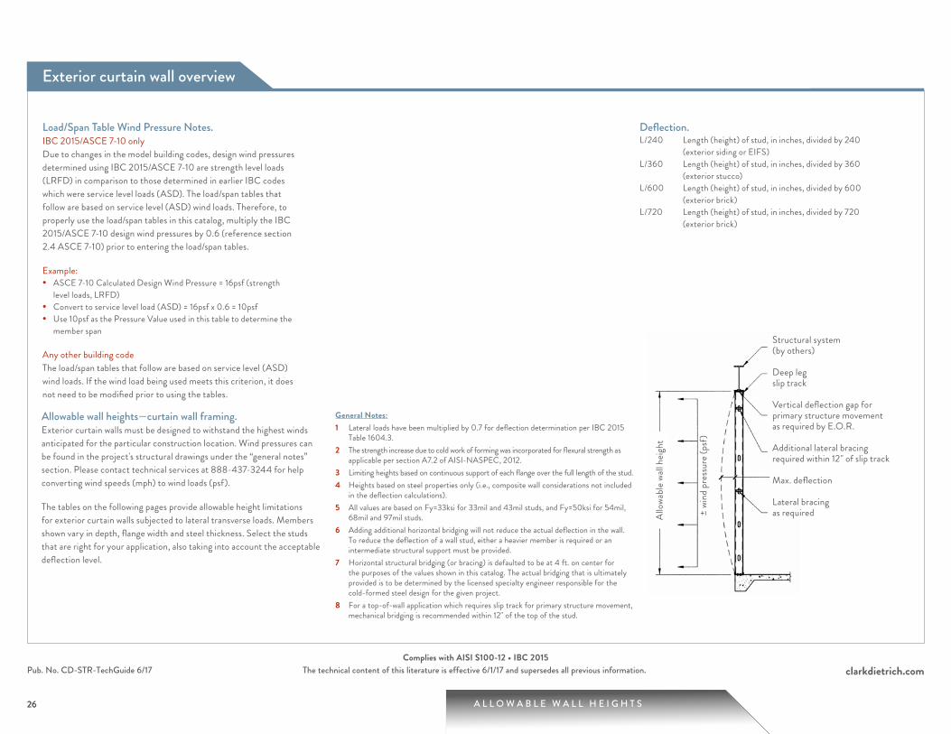
A L L O W A B L E W A L L H E I G H T S
clarkdietrich.comThe technical content of this literature is effective 6/1/17 and supersedes all previous information.
26
Pub. No. CD-STR-TechGuide 6/17Complies with AISI S100-12 • IBC 2015
26
Notes:1 Studs are checked for simple-span deflection and stress. Stress calculations are
made for mid-span fully braced moment, end shear through the unperforated section, and shear moment interaction through the perforated section 10" away from the end bearing.
2 A 1/3 stress increase is not used.3 Limiting heights are based on continuous lateral support of each flange over the
full height of the stud.4 Listed limiting heights are based on steel properties only.
5 Web crippling check based on 1-inch end bearing. Where limiting heights are followed by "e," web stiffeners are required.
6 For bending, studs are assumed to be adequately braced to develop full allowable moment capacity. Stud distortional buckling based on an assumed Kφ=0.
7 Cells marked with an " * " have h/t > 200, and thus require end stiffeners.8 Capacities are calculated according to the AISI-NASPEC S100-2012. A
1-1/2" by 4" knockout spaced no closer than 24" o.c. is assumed.
9 All values are based on Fy=33ksi for 33mil and 43mil studs, and Fy=50ksi for 54mil, 68mil and 97mil studs.
10 For deflection calculations, 15psf and higher wind pressures have been multiplied by 0.7, in accordance with footnote "f" of IBC table 1604.3.
11 Lateral loads have not been modified for strength checks. Full loads are applied.
Exterior curtain wall overview
Allowable wall heights—curtain wall framing.Exterior curtain walls must be designed to withstand the highest winds anticipated for the particular construction location. Wind pressures can be found in the project's structural drawings under the “general notes” section. Please contact technical services at 888-437-3244 for help converting wind speeds (mph) to wind loads (psf).
The tables on the following pages provide allowable height limitations for exterior curtain walls subjected to lateral transverse loads. Members shown vary in depth, flange width and steel thickness. Select the studs that are right for your application, also taking into account the acceptable deflection level.
General Notes:1 Lateral loads have been multiplied by 0.7 for deflection determination per IBC 2015
Table 1604.3.2 The strength increase due to cold work of forming was incorporated for flexural strength as
applicable per section A7.2 of AISI-NASPEC, 2012.3 Limiting heights based on continuous support of each flange over the full length of the stud.4 Heights based on steel properties only (i.e., composite wall considerations not included
in the deflection calculations).5 All values are based on Fy=33ksi for 33mil and 43mil studs, and Fy=50ksi for 54mil,
68mil and 97mil studs. 6 Adding additional horizontal bridging will not reduce the actual deflection in the wall.
To reduce the deflection of a wall stud, either a heavier member is required or an intermediate structural support must be provided.
7 Horizontal structural bridging (or bracing) is defaulted to be at 4 ft. on center for the purposes of the values shown in this catalog. The actual bridging that is ultimately provided is to be determined by the licensed specialty engineer responsible for the cold-formed steel design for the given project.
8 For a top-of-wall application which requires slip track for primary structure movement, mechanical bridging is recommended within 12" of the top of the stud.
Deflection.L/240 Length (height) of stud, in inches, divided by 240
(exterior siding or EIFS)L/360 Length (height) of stud, in inches, divided by 360
(exterior stucco)L/600 Length (height) of stud, in inches, divided by 600
(exterior brick)L/720 Length (height) of stud, in inches, divided by 720
(exterior brick)
± wi
nd p
ress
ure (
psf)
Allo
wabl
e wall
heig
ht
Structural system (by others)
Deep leg slip track
Vertical deflection gap for primary structure movement as required by E.O.R.
Additional lateral bracing required within 12" of slip track
Max. deflection
Lateral bracing as required
Load/Span Table Wind Pressure Notes.IBC 2015/ASCE 7-10 onlyDue to changes in the model building codes, design wind pressures determined using IBC 2015/ASCE 7-10 are strength level loads (LRFD) in comparison to those determined in earlier IBC codes which were service level loads (ASD). The load/span tables that follow are based on service level (ASD) wind loads. Therefore, to properly use the load/span tables in this catalog, multiply the IBC 2015/ASCE 7-10 design wind pressures by 0.6 (reference section 2.4 ASCE 7-10) prior to entering the load/span tables.
Example:• ASCE 7-10 Calculated Design Wind Pressure = 16psf (strength
level loads, LRFD)• Convert to service level load (ASD) = 16psf x 0.6 = 10psf• Use 10psf as the Pressure Value used in this table to determine the
member span
Any other building codeThe load/span tables that follow are based on service level (ASD) wind loads. If the wind load being used meets this criterion, it does not need to be modified prior to using the tables.
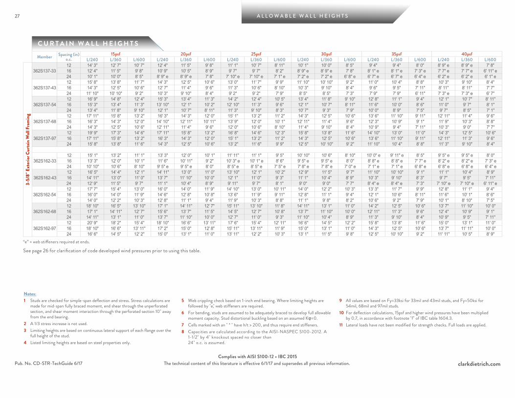
27 A L L O W A B L E W A L L H E I G H T S
clarkdietrich.comThe technical content of this literature is effective 6/1/17 and supersedes all previous information.Pub. No. CD-STR-TechGuide 6/17Complies with AISI S100-12 • IBC 2015
C U R T A I N W A L L H E I G H T S
Notes:1 Studs are checked for simple-span deflection and stress. Stress calculations are
made for mid-span fully braced moment, end shear through the unperforated section, and shear moment interaction through the perforated section 10" away from the end bearing.
2 A 1/3 stress increase is not used.3 Limiting heights are based on continuous lateral support of each flange over the
full height of the stud.4 Listed limiting heights are based on steel properties only.
5 Web crippling check based on 1-inch end bearing. Where limiting heights are followed by "e," web stiffeners are required.
6 For bending, studs are assumed to be adequately braced to develop full allowable moment capacity. Stud distortional buckling based on an assumed Kφ=0.
7 Cells marked with an " * " have h/t > 200, and thus require end stiffeners.8 Capacities are calculated according to the AISI-NASPEC S100-2012. A
1-1/2" by 4" knockout spaced no closer than 24" o.c. is assumed.
9 All values are based on Fy=33ksi for 33mil and 43mil studs, and Fy=50ksi for 54mil, 68mil and 97mil studs.
10 For deflection calculations, 15psf and higher wind pressures have been multiplied by 0.7, in accordance with footnote "f" of IBC table 1604.3.
11 Lateral loads have not been modified for strength checks. Full loads are applied.
Member Spacing (in) o.c.
15psf 20psf 25psf 30psf 35psf 40psfL/240 L/360 L/600 L/240 L/360 L/600 L/240 L/360 L/600 L/240 L/360 L/600 L/240 L/360 L/600 L/240 L/360 L/600
3-5/
8" E
xter
ior C
urta
in W
all F
ram
ing
362S137-3312 14' 3" 12' 7" 10' 7" 12' 4" 11' 5" 9' 8" 11' 1" 10' 7" 8' 11" 10' 1" 10' 0" 8' 5" 9' 4" 9' 4" 8' 0" 8' 9" e 8' 9" e 7' 8" 16 12' 4" 11' 5" 9' 8" 10' 9" 10' 5" 8' 9" 9' 7" 9' 7" 8' 2" 8' 9" e 8' 9" e 7' 8" 8' 1" e 8' 1" e 7' 3" e 7' 7" e 7' 7" e 6' 11" e24 10' 1" 10' 0" 8' 5" 8' 9" e 8' 9" e 7' 8" 7' 10" e 7' 10" e 7' 1" e 7' 2" e 7' 2" e 6' 8" e 6' 7" e 6' 7" e 6' 4" e 6' 2" e 6' 2" e 6' 1" e
362S137-4312 15' 8" 13' 8" 11' 7" 14' 3" 12' 5" 10' 6" 13' 0" 11' 7" 9' 9" 11' 10" 10' 10" 9' 2" 11' 0" 10' 4" 8' 8" 10' 3" 9' 10" 8' 4" 16 14' 3" 12' 5" 10' 6" 12' 7" 11' 4" 9' 6" 11' 3" 10' 6" 8' 10" 10' 3" 9' 10" 8' 4" 9' 6" 9' 5" 7' 11" 8' 11" 8' 11" 7' 7" 24 11' 10" 10' 10" 9' 2" 10' 3" 9' 10" 8' 4" 9' 2" 9' 2" 7' 9" 8' 5" 8' 5" 7' 3" 7' 9" 7' 9" 6' 11" 7' 3" e 7' 3" e 6' 7"
362S137-5412 16' 9" 14' 8" 12' 4" 15' 3" 13' 4" 11' 3" 14' 2" 12' 4" 10' 5" 13' 4" 11' 8" 9' 10" 12' 8" 11' 1" 9' 4" 12' 1" 10' 7" 8' 11" 16 15' 3" 13' 4" 11' 3" 13' 10" 12' 1" 10' 2" 12' 10" 11' 3" 9' 6" 12' 1" 10' 7" 8' 11" 11' 6" 10' 0" 8' 6" 11' 0" 9' 7" 8' 1" 24 13' 4" 11' 8" 9' 10" 12' 1" 10' 7" 8' 11" 11' 3" 9' 10" 8' 3" 10' 7" 9' 3" 7' 9" 10' 0" 8' 9" 7' 5" 9' 7" 8' 5" 7' 1"
362S137-6812 17' 11" 15' 8" 13' 2" 16' 3" 14' 3" 12' 0" 15' 1" 13' 2" 11' 2" 14' 3" 12' 5" 10' 6" 13' 6" 11' 10" 9' 11" 12' 11" 11' 4" 9' 6" 16 16' 3" 14' 3" 12' 0" 14' 10" 12' 11" 10' 11" 13' 9" 12' 0" 10' 1" 12' 11" 11' 4" 9' 6" 12' 3" 10' 9" 9' 1" 11' 9" 10' 3" 8' 8" 24 14' 3" 12' 5" 10' 6" 12' 11" 11' 4" 9' 6" 12' 0" 10' 6" 8' 10" 11' 4" 9' 10" 8' 4" 10' 9" 9' 4" 7' 11" 10' 3" 9' 0" 7' 7"
362S137-9712 19' 9" 17' 3" 14' 6" 17' 11" 15' 8" 13' 2" 16' 8" 14' 6" 12' 3" 15' 8" 13' 8" 11' 6" 14' 10" 13' 0" 11' 0" 14' 3" 12' 5" 10' 6" 16 17' 11" 15' 8" 13' 2" 16' 3" 14' 3" 12' 0" 15' 1" 13' 2" 11' 2" 14' 3" 12' 5" 10' 6" 13' 6" 11' 10" 9' 11" 12' 11" 11' 3" 9' 6" 24 15' 8" 13' 8" 11' 6" 14' 3" 12' 5" 10' 6" 13' 2" 11' 6" 9' 9" 12' 5" 10' 10" 9' 2" 11' 10" 10' 4" 8' 8" 11' 3" 9' 10" 8' 4"
362S162-3312 15' 1" 13' 2" 11' 1" 13' 3" 12' 0" 10' 1" 11' 11" 11' 1" 9' 5" 10' 10" 10' 6" 8' 10" 10' 0" e 9' 11" e 8' 5" 9' 5" e 9' 5" e 8' 0" 16 13' 3" 12' 0" 10' 1" 11' 6" 10' 11" 9' 2" 10' 3" e 10' 1" e 8' 6" 9' 5" e 9' 5" e 8' 0" 8' 8" e 8' 8" e 7' 7" e 8' 2" e 8' 2" e 7' 3" e24 10' 10" 10' 6" 8' 10" 9' 5" e 9' 5" e 8' 0" 8' 5" e 8' 5" e 7' 5" e 7' 8" e 7' 8" e 7' 0" e 7' 1" e 7' 1" e 6' 8" e 6' 8" e 6' 8" e 6' 4" e
362S162-4312 16' 5" 14' 4" 12' 1" 14' 11" 13' 0" 11' 0" 13' 10" 12' 1" 10' 2" 12' 9" 11' 5" 9' 7" 11' 10" 10' 10" 9' 1" 11' 1" 10' 4" 8' 9" 16 14' 11" 13' 0" 11' 0" 13' 7" 11' 10" 10' 0" 12' 1" 11' 0" 9' 3" 11' 1" 10' 4" 8' 9" 10' 3" 9' 10" 8' 3" 9' 7" 9' 5" 7' 11" 24 12' 9" 11' 5" 9' 7" 11' 1" 10' 4" 8' 9" 9' 11" 9' 7" 8' 1" 9' 0" 9' 0" 7' 7" 8' 4" e 8' 4" e 7' 3" 7' 10" e 7' 10" e 6' 11" e
362S162-5412 17' 7" 15' 4" 13' 0" 16' 0" 14' 0" 11' 9" 14' 10" 13' 0" 10' 11" 14' 0" 12' 2" 10' 3" 13' 3" 11' 7" 9' 9" 12' 8" 11' 1" 9' 4" 16 16' 0" 14' 0" 11' 9" 14' 6" 12' 8" 10' 8" 13' 6" 11' 9" 9' 11" 12' 8" 11' 1" 9' 4" 12' 1" 10' 6" 8' 11" 11' 6" 10' 1" 8' 6" 24 14' 0" 12' 2" 10' 3" 12' 8" 11' 1" 9' 4" 11' 9" 10' 3" 8' 8" 11' 1" 9' 8" 8' 2" 10' 6" 9' 2" 7' 9" 10' 1" 8' 10" 7' 5"
362S162-6812 18' 10" 16' 5" 13' 10" 17' 1" 14' 11" 12' 7" 15' 11" 13' 10" 11' 8" 14' 11" 13' 1" 11' 0" 14' 2" 12' 5" 10' 6" 13' 7" 11' 10" 10' 0" 16 17' 1" 14' 11" 12' 7" 15' 6" 13' 7" 11' 5" 14' 5" 12' 7" 10' 8" 13' 7" 11' 10" 10' 0" 12' 11" 11' 3" 9' 6" 12' 4" 10' 9" 9' 1" 24 14' 11" 13' 1" 11' 0" 13' 7" 11' 10" 10' 0" 12' 7" 11' 0" 9' 3" 11' 10" 10' 4" 8' 9" 11' 3" 9' 10" 8' 4" 10' 9" 9' 5" 7' 11"
362S162-9712 20' 9" 18' 2" 15' 4" 18' 10" 16' 6" 13' 11" 17' 6" 15' 4" 12' 11" 16' 6" 14' 5" 12' 2" 15' 8" 13' 8" 11' 6" 15' 0" 13' 1" 11' 0" 16 18' 10" 16' 6" 13' 11" 17' 2" 15' 0" 12' 8" 15' 11" 13' 11" 11' 9" 15' 0" 13' 1" 11' 0" 14' 3" 12' 5" 10' 6" 13' 7" 11' 11" 10' 0" 24 16' 6" 14' 5" 12' 2" 15' 0" 13' 1" 11' 0" 13' 11" 12' 2" 10' 3" 13' 1" 11' 5" 9' 8" 12' 5" 10' 10" 9' 2" 11' 11" 10' 5" 8' 9"
“e” = web stiffeners required at ends.
See page 26 for clarification of code developed wind pressures prior to using this table.
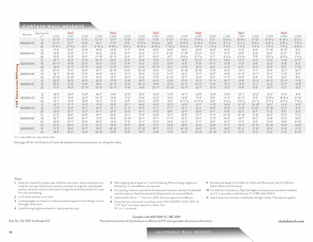
A L L O W A B L E W A L L H E I G H T S
clarkdietrich.comThe technical content of this literature is effective 6/1/17 and supersedes all previous information.
28
Pub. No. CD-STR-TechGuide 6/17Complies with AISI S100-12 • IBC 2015
C U R T A I N W A L L H E I G H T S
28
Notes:1 Studs are checked for simple-span deflection and stress. Stress calculations are
made for mid-span fully braced moment, end shear through the unperforated section, and shear moment interaction through the perforated section 10" away from the end bearing.
2 A 1/3 stress increase is not used.3 Limiting heights are based on continuous lateral support of each flange over the
full height of the stud.4 Listed limiting heights are based on steel properties only.
5 Web crippling check based on 1-inch end bearing. Where limiting heights are followed by "e," web stiffeners are required.
6 For bending, studs are assumed to be adequately braced to develop full allowable moment capacity. Stud distortional buckling based on an assumed Kφ=0.
7 Cells marked with an " * " have h/t > 200, and thus require end stiffeners.8 Capacities are calculated according to the AISI-NASPEC S100-2012. A
1-1/2" by 4" knockout spaced no closer than 24" o.c. is assumed.
9 All values are based on Fy=33ksi for 33mil and 43mil studs, and Fy=50ksi for 54mil, 68mil and 97mil studs.
10 For deflection calculations, 15psf and higher wind pressures have been multiplied by 0.7, in accordance with footnote "f" of IBC table 1604.3.
11 Lateral loads have not been modified for strength checks. Full loads are applied.
Member Spacing (in) o.c.
15psf 20psf 25psf 30psf 35psf 40psfL/240 L/360 L/600 L/240 L/360 L/600 L/240 L/360 L/600 L/240 L/360 L/600 L/240 L/360 L/600 L/240 L/360 L/600
3-5/
8" E
xter
ior C
urta
in W
all F
ram
ing
362S200-3312 15' 11" 13' 11" 11' 8" 13' 11" 12' 7" 10' 8" 12' 5" 11' 8" 9' 10" 11' 4" e 11' 0" e 9' 3" 10' 6" e 10' 6" e 8' 10" 9' 10" e 9' 10" e 8' 5" e16 13' 11" 12' 7" 10' 8" 12' 1" 11' 5" 9' 8" 10' 9" e 10' 8" e 9' 0" 9' 10" e 9' 10" e 8' 5" e 9' 1" e 9' 1" e 8' 0" e 8' 6" e 8' 6" e 7' 8" e24 11' 4" e 11' 0" e 9' 3" 9' 10" e 9' 10" e 8' 5" e 8' 10" e 8' 10" e 7' 10" e 8' 0" e 8' 0" e 7' 4" e 7' 5" e 7' 5" e 7' 0" e 7' 0" e 7' 0" e 6' 8" e
362S200-4312 17' 4" 15' 2" 12' 9" 15' 9" 13' 9" 11' 7" 14' 8" 12' 9" 10' 9" 13' 8" 12' 0" 10' 2" 12' 8" 11' 5" 9' 8" 11' 10" 10' 11" 9' 3" 16 15' 9" 13' 9" 11' 7" 14' 4" 12' 6" 10' 7" 13' 0" 11' 7" 9' 10" 11' 10" 10' 11" 9' 3" 11' 0" 10' 5" 8' 9" 10' 3" 9' 11" 8' 4" 24 13' 8" 12' 0" 10' 2" 11' 10" 10' 11" 9' 3" 10' 7" 10' 2" 8' 7" 9' 8" e 9' 7" e 8' 1" 9' 0" e 9' 0" e 7' 8" 8' 5" e 8' 5" e 7' 4" e
362S200-5412 18' 7" 16' 3" 13' 8" 16' 11" 14' 9" 12' 5" 15' 8" 13' 8" 11' 7" 14' 9" 12' 11" 10' 11" 14' 0" 12' 3" 10' 4" 13' 5" 11' 9" 9' 11" 16 16' 11" 14' 9" 12' 5" 15' 4" 13' 5" 11' 4" 14' 3" 12' 5" 10' 6" 13' 5" 11' 9" 9' 11" 12' 9" 11' 2" 9' 5" 12' 2" 10' 8" 9' 0" 24 14' 9" 12' 11" 10' 11" 13' 5" 11' 9" 9' 11" 12' 5" 10' 11" 9' 2" 11' 9" 10' 3" 8' 8" 11' 2" 9' 9" 8' 2" 10' 8" 9' 4" 7' 10"
362S200-6812 19' 11" 17' 5" 14' 8" 18' 1" 15' 10" 13' 4" 16' 10" 14' 8" 12' 5" 15' 10" 13' 10" 11' 8" 15' 0" 13' 1" 11' 1" 14' 4" 12' 7" 10' 7" 16 18' 1" 15' 10" 13' 4" 16' 5" 14' 4" 12' 1" 15' 3" 13' 4" 11' 3" 14' 4" 12' 7" 10' 7" 13' 8" 11' 11" 10' 1" 13' 1" 11' 5" 9' 7" 24 15' 10" 13' 10" 11' 8" 14' 4" 12' 7" 10' 7" 13' 4" 11' 8" 9' 10" 12' 7" 11' 0" 9' 3" 11' 11" 10' 5" 8' 9" 11' 5" 10' 0" 8' 5"
362S200-9712 22' 0" 19' 3" 16' 3" 20' 0" 17' 6" 14' 9" 18' 7" 16' 3" 13' 8" 17' 6" 15' 3" 12' 11" 16' 7" 14' 6" 12' 3" 15' 11" 13' 11" 11' 8" 16 20' 0" 17' 6" 14' 9" 18' 2" 15' 11" 13' 5" 16' 11" 14' 9" 12' 5" 15' 11" 13' 11" 11' 8" 15' 1" 13' 2" 11' 1" 14' 5" 12' 7" 10' 8" 24 17' 6" 15' 3" 12' 11" 15' 11" 13' 11" 11' 8" 14' 9" 12' 11" 10' 10" 13' 11" 12' 1" 10' 3" 13' 2" 11' 6" 9' 9" 12' 7" 11' 0" 9' 3"
362S250-4312 18' 4" 16' 0" 13' 6" 16' 7" 14' 6" 12' 3" 15' 5" 13' 6" 11' 4" 14' 1" 12' 8" 10' 8" 13' 0" 12' 1" 10' 2" 12' 2" 11' 6" 9' 9" 16 16' 7" 14' 6" 12' 3" 14' 11" 13' 2" 11' 2" 13' 4" 12' 3" 10' 4" 12' 2" 11' 6" 9' 9" 11' 3" 10' 11" 9' 3" 10' 6" e 10' 6" e 8' 10" 24 14' 1" 12' 8" 10' 8" 12' 2" 11' 6" 9' 9" 10' 11" 10' 8" 9' 0" 9' 11" e 9' 11" e 8' 6" 9' 2" e 9' 2" e 8' 1" e 8' 7" e 8' 7" e 7' 9" e
362S250-5412 19' 7" 17' 1" 14' 5" 17' 9" 15' 6" 13' 1" 16' 6" 14' 5" 12' 2" 15' 6" 13' 7" 11' 5" 14' 9" 12' 11" 10' 10" 14' 1" 12' 4" 10' 5" 16 17' 9" 15' 6" 13' 1" 16' 2" 14' 1" 11' 11" 15' 0" 13' 1" 11' 1" 14' 1" 12' 4" 10' 5" 13' 5" 11' 8" 9' 10" 12' 10" 11' 2" 9' 5" 24 15' 6" 13' 7" 11' 5" 14' 1" 12' 4" 10' 5" 13' 1" 11' 5" 9' 8" 12' 4" 10' 9" 9' 1" 11' 8" 10' 3" 8' 7" 11' 2" 9' 9" 8' 3"
362S250-6812 21' 0" 18' 5" 15' 6" 19' 1" 16' 8" 14' 1" 17' 9" 15' 6" 13' 1" 16' 8" 14' 7" 12' 4" 15' 10" 13' 10" 11' 8" 15' 2" 13' 3" 11' 2" 16 19' 1" 16' 8" 14' 1" 17' 4" 15' 2" 12' 10" 16' 1" 14' 1" 11' 11" 15' 2" 13' 3" 11' 2" 14' 5" 12' 7" 10' 7" 13' 9" 12' 0" 10' 2" 24 16' 8" 14' 7" 12' 4" 15' 2" 13' 3" 11' 2" 14' 1" 12' 4" 10' 5" 13' 3" 11' 7" 9' 9" 12' 7" 11' 0" 9' 3" 12' 0" 10' 6" 8' 10"
362S250-9712 23' 4" 20' 4" 17' 2" 21' 2" 18' 6" 15' 7" 19' 8" 17' 2" 14' 6" 18' 6" 16' 2" 13' 8" 17' 7" 15' 4" 12' 11" 16' 10" 14' 8" 12' 5" 16 21' 2" 18' 6" 15' 7" 19' 3" 16' 10" 14' 2" 17' 10" 15' 7" 13' 2" 16' 10" 14' 8" 12' 5" 16' 0" 13' 11" 11' 9" 15' 3" 13' 4" 11' 3" 24 18' 6" 16' 2" 13' 8" 16' 10" 14' 8" 12' 5" 15' 7" 13' 8" 11' 6" 14' 8" 12' 10" 10' 10" 13' 11" 12' 2" 10' 3" 13' 4" 11' 8" 9' 10"
“e” = web stiffeners required at ends.
See page 26 for clarification of code developed wind pressures prior to using this table.

29 A L L O W A B L E W A L L H E I G H T S
clarkdietrich.comThe technical content of this literature is effective 6/1/17 and supersedes all previous information.Pub. No. CD-STR-TechGuide 6/17Complies with AISI S100-12 • IBC 2015
C U R T A I N W A L L H E I G H T S
Notes:1 Studs are checked for simple-span deflection and stress. Stress calculations are
made for mid-span fully braced moment, end shear through the unperforated section, and shear moment interaction through the perforated section 10" away from the end bearing.
2 A 1/3 stress increase is not used.3 Limiting heights are based on continuous lateral support of each flange over the
full height of the stud.4 Listed limiting heights are based on steel properties only.
5 Web crippling check based on 1-inch end bearing. Where limiting heights are followed by "e," web stiffeners are required.
6 For bending, studs are assumed to be adequately braced to develop full allowable moment capacity. Stud distortional buckling based on an assumed Kφ=0.
7 Cells marked with an " * " have h/t > 200, and thus require end stiffeners.8 Capacities are calculated according to the AISI-NASPEC S100-2012. A
1-1/2" by 4" knockout spaced no closer than 24" o.c. is assumed.
9 All values are based on Fy=33ksi for 33mil and 43mil studs, and Fy=50ksi for 54mil, 68mil and 97mil studs.
10 For deflection calculations, 15psf and higher wind pressures have been multiplied by 0.7, in accordance with footnote "f" of IBC table 1604.3.
11 Lateral loads have not been modified for strength checks. Full loads are applied.
Member Spacing (in) o.c.
15psf 20psf 25psf 30psf 35psf 40psfL/240 L/360 L/600 L/240 L/360 L/600 L/240 L/360 L/600 L/240 L/360 L/600 L/240 L/360 L/600 L/240 L/360 L/600
4" E
xter
ior C
urta
in W
all F
ram
ing
400S137-3312 15' 1" 13' 7" 11' 6" 13' 1" 12' 4" 10' 5" 11' 8" 11' 6" 9' 8" 10' 8" 10' 8" 9' 1" 9' 10" e 9' 10" e 8' 8" 9' 3" e 9' 3" e 8' 3" e16 13' 1" 12' 4" 10' 5" 11' 4" 11' 3" 9' 6" 10' 1" e 10' 1" e 8' 9" 9' 3" e 9' 3" e 8' 3" e 8' 7" e 8' 7" e 7' 10" e 8' 0" e 8' 0" e 7' 6" e24 10' 8" 10' 8" 9' 1" 9' 3" e 9' 3" e 8' 3" e 8' 3" e 8' 3" e 7' 8" e 7' 6" e 7' 6" e 7' 3" e 7' 0" e 7' 0" e 6' 10" e 6' 6" e 6' 6" e 6' 6" e
400S137-4312 16' 11" 14' 9" 12' 6" 15' 4" 13' 5" 11' 4" 13' 9" 12' 6" 10' 6" 12' 7" 11' 9" 9' 11" 11' 7" 11' 2" 9' 5" 10' 10" 10' 8" 9' 0" 16 15' 4" 13' 5" 11' 4" 13' 4" 12' 2" 10' 4" 11' 11" 11' 4" 9' 7" 10' 10" 10' 8" 9' 0" 10' 1" 10' 1" 8' 6" 9' 5" 9' 5" 8' 2" 24 12' 7" 11' 9" 9' 11" 10' 10" 10' 8" 9' 0" 9' 9" 9' 9" 8' 4" 8' 11" 8' 11" 7' 10" 8' 3" e 8' 3" e 7' 6" 7' 8" e 7' 8" e 7' 2" e
400S137-5412 18' 1" 15' 10" 13' 4" 16' 6" 14' 5" 12' 2" 15' 3" 13' 4" 11' 3" 14' 5" 12' 7" 10' 7" 13' 8" 11' 11" 10' 1" 13' 1" 11' 5" 9' 8" 16 16' 6" 14' 5" 12' 2" 15' 0" 13' 1" 11' 0" 13' 11" 12' 2" 10' 3" 13' 1" 11' 5" 9' 8" 12' 5" 10' 10" 9' 2" 11' 10" 10' 4" 8' 9" 24 14' 5" 12' 7" 10' 7" 13' 1" 11' 5" 9' 8" 12' 2" 10' 7" 8' 11" 11' 5" 10' 0" 8' 5" 10' 10" 9' 6" 8' 0" 10' 4" 9' 1" 7' 8"
400S137-6812 19' 5" 16' 11" 14' 3" 17' 7" 15' 5" 13' 0" 16' 4" 14' 3" 12' 0" 15' 5" 13' 5" 11' 4" 14' 7" 12' 9" 10' 9" 14' 0" 12' 2" 10' 4" 16 17' 7" 15' 5" 13' 0" 16' 0" 14' 0" 11' 9" 14' 10" 13' 0" 10' 11" 14' 0" 12' 2" 10' 4" 13' 3" 11' 7" 9' 9" 12' 8" 11' 1" 9' 4" 24 15' 5" 13' 5" 11' 4" 14' 0" 12' 2" 10' 4" 13' 0" 11' 4" 9' 7" 12' 2" 10' 8" 9' 0" 11' 7" 10' 2" 8' 7" 11' 1" 9' 8" 8' 2"
400S137-9712 21' 4" 18' 8" 15' 9" 19' 5" 16' 11" 14' 3" 18' 0" 15' 9" 13' 3" 16' 11" 14' 10" 12' 6" 16' 1" 14' 1" 11' 10" 15' 5" 13' 5" 11' 4" 16 19' 5" 16' 11" 14' 3" 17' 7" 15' 5" 13' 0" 16' 4" 14' 3" 12' 1" 15' 5" 13' 5" 11' 4" 14' 7" 12' 9" 10' 9" 14' 0" 12' 3" 10' 4" 24 16' 11" 14' 10" 12' 6" 15' 5" 13' 5" 11' 4" 14' 3" 12' 6" 10' 6" 13' 5" 11' 9" 9' 11" 12' 9" 11' 2" 9' 5" 12' 3" 10' 8" 9' 0"
400S162-3312 16' 2" 14' 3" 12' 0" 14' 0" 12' 11" 10' 11" 12' 7" 12' 0" 10' 1" 11' 5" e 11' 4" e 9' 6" 10' 7" e 10' 7" e 9' 1" 9' 11" e 9' 11" e 8' 8" e16 14' 0" 12' 11" 10' 11" 12' 2" 11' 9" 9' 11" 10' 10" e 10' 10" e 9' 2" 9' 11" e 9' 11" e 8' 8" e 9' 2" e 9' 2" e 8' 3" e 8' 7" e 8' 7" e 7' 10" e24 11' 5" e 11' 4" e 9' 6" 9' 11" e 9' 11" e 8' 8" e 8' 10" e 8' 10" e 8' 0" e 8' 1" e 8' 1" e 7' 7" e 7' 6" e 7' 6" e 7' 2" e 7' 0" e 7' 0" e 6' 10" e
400S162-4312 17' 9" 15' 6" 13' 1" 16' 1" 14' 1" 11' 10" 14' 10" 13' 1" 11' 0" 13' 6" 12' 3" 10' 4" 12' 6" 11' 8" 9' 10" 11' 9" 11' 2" 9' 5" 16 16' 1" 14' 1" 11' 10" 14' 4" 12' 9" 10' 9" 12' 10" 11' 10" 10' 0" 11' 9" 11' 2" 9' 5" 10' 10" 10' 7" 8' 11" 10' 2" 10' 2" 8' 7" 24 13' 6" 12' 3" 10' 4" 11' 9" 11' 2" 9' 5" 10' 6" 10' 4" 8' 9" 9' 7" e 9' 7" e 8' 3" 8' 10" e 8' 10" e 7' 10" 8' 3" e 8' 3" e 7' 6" e
400S162-5412 19' 0" 16' 7" 14' 0" 17' 3" 15' 1" 12' 9" 16' 0" 14' 0" 11' 10" 15' 1" 13' 2" 11' 1" 14' 4" 12' 6" 10' 7" 13' 8" 12' 0" 10' 1" 16 17' 3" 15' 1" 12' 9" 15' 8" 13' 8" 11' 7" 14' 7" 12' 9" 10' 9" 13' 8" 12' 0" 10' 1" 13' 0" 11' 4" 9' 7" 12' 5" 10' 10" 9' 2" 24 15' 1" 13' 2" 11' 1" 13' 8" 12' 0" 10' 1" 12' 9" 11' 1" 9' 4" 12' 0" 10' 5" 8' 10" 11' 4" 9' 11" 8' 5" 10' 10" 9' 6" 8' 0"
400S162-6812 20' 4" 17' 9" 15' 0" 18' 6" 16' 2" 13' 7" 17' 2" 15' 0" 12' 8" 16' 2" 14' 1" 11' 11" 15' 4" 13' 5" 11' 4" 14' 8" 12' 10" 10' 10" 16 18' 6" 16' 2" 13' 7" 16' 9" 14' 8" 12' 4" 15' 7" 13' 7" 11' 6" 14' 8" 12' 10" 10' 10" 13' 11" 12' 2" 10' 3" 13' 4" 11' 8" 9' 10" 24 16' 2" 14' 1" 11' 11" 14' 8" 12' 10" 10' 10" 13' 7" 11' 11" 10' 0" 12' 10" 11' 2" 9' 5" 12' 2" 10' 8" 9' 0" 11' 8" 10' 2" 8' 7"
400S162-9712 22' 5" 19' 7" 16' 7" 20' 5" 17' 10" 15' 0" 18' 11" 16' 7" 13' 11" 17' 10" 15' 7" 13' 2" 16' 11" 14' 9" 12' 6" 16' 2" 14' 2" 11' 11" 16 20' 5" 17' 10" 15' 0" 18' 6" 16' 2" 13' 8" 17' 2" 15' 0" 12' 8" 16' 2" 14' 2" 11' 11" 15' 5" 13' 5" 11' 4" 14' 9" 12' 10" 10' 10" 24 17' 10" 15' 7" 13' 2" 16' 2" 14' 2" 11' 11" 15' 0" 13' 2" 11' 1" 14' 2" 12' 4" 10' 5" 13' 5" 11' 9" 9' 11" 12' 10" 11' 3" 9' 6"
“e” = web stiffeners required at ends.
See page 26 for clarification of code developed wind pressures prior to using this table.

A L L O W A B L E W A L L H E I G H T S
clarkdietrich.comThe technical content of this literature is effective 6/1/17 and supersedes all previous information.
30
Pub. No. CD-STR-TechGuide 6/17Complies with AISI S100-12 • IBC 2015
C U R T A I N W A L L H E I G H T S
30
Notes:1 Studs are checked for simple-span deflection and stress. Stress calculations are
made for mid-span fully braced moment, end shear through the unperforated section, and shear moment interaction through the perforated section 10" away from the end bearing.
2 A 1/3 stress increase is not used.3 Limiting heights are based on continuous lateral support of each flange over the
full height of the stud.4 Listed limiting heights are based on steel properties only.
5 Web crippling check based on 1-inch end bearing. Where limiting heights are followed by "e," web stiffeners are required.
6 For bending, studs are assumed to be adequately braced to develop full allowable moment capacity. Stud distortional buckling based on an assumed Kφ=0.
7 Cells marked with an " * " have h/t > 200, and thus require end stiffeners.8 Capacities are calculated according to the AISI-NASPEC S100-2012. A
1-1/2" by 4" knockout spaced no closer than 24" o.c. is assumed.
9 All values are based on Fy=33ksi for 33mil and 43mil studs, and Fy=50ksi for 54mil, 68mil and 97mil studs.
10 For deflection calculations, 15psf and higher wind pressures have been multiplied by 0.7, in accordance with footnote "f" of IBC table 1604.3.
11 Lateral loads have not been modified for strength checks. Full loads are applied.
Member Spacing (in) o.c.
15psf 20psf 25psf 30psf 35psf 40psfL/240 L/360 L/600 L/240 L/360 L/600 L/240 L/360 L/600 L/240 L/360 L/600 L/240 L/360 L/600 L/240 L/360 L/600
4" E
xter
ior C
urta
in W
all F
ram
ing
400S200-3312 17' 0" 15' 0" 12' 7" 14' 9" 13' 7" 11' 6" 13' 2" e 12' 7" 10' 8" 12' 0" e 11' 10" e 10' 0" 11' 1" e 11' 1" e 9' 6" e 10' 5" e 10' 5" e 9' 1" e16 14' 9" 13' 7" 11' 6" 12' 9" e 12' 4" e 10' 5" 11' 5" e 11' 5" e 9' 8" 10' 5" e 10' 5" e 9' 1" e 9' 8" e 9' 8" e 8' 8" e 9' 0" e 9' 0" e 8' 3" e24 12' 0" e 11' 10" e 10' 0" 10' 5" e 10' 5" e 9' 1" e 9' 4" e 9' 4" e 8' 5" e 8' 6" e 8' 6" e 7' 11" e 7' 10" e 7' 10" e 7' 7" e 7' 4" e 7' 4" e 7' 3" e
400S200-4312 18' 8" 16' 4" 13' 9" 17' 0" 14' 10" 12' 6" 15' 9" 13' 9" 11' 7" 14' 6" 13' 0" 10' 11" 13' 5" 12' 4" 10' 5" 12' 7" 11' 9" 9' 11" 16 17' 0" 14' 10" 12' 6" 15' 4" 13' 6" 11' 4" 13' 9" 12' 6" 10' 7" 12' 7" 11' 9" 9' 11" 11' 7" 11' 2" 9' 5" 10' 10" e 10' 8" e 9' 0" 24 14' 6" 13' 0" 10' 11" 12' 7" 11' 9" 9' 11" 11' 3" e 10' 11" 9' 3" 10' 3" e 10' 3" e 8' 8" 9' 6" e 9' 6" e 8' 3" e 8' 11" e 8' 11" e 7' 11" e
400S200-5412 20' 1" 17' 6" 14' 9" 18' 3" 15' 11" 13' 5" 16' 11" 14' 9" 12' 6" 15' 11" 13' 11" 11' 9" 15' 1" 13' 3" 11' 2" 14' 6" 12' 8" 10' 8" 16 18' 3" 15' 11" 13' 5" 16' 7" 14' 6" 12' 2" 15' 4" 13' 5" 11' 4" 14' 6" 12' 8" 10' 8" 13' 9" 12' 0" 10' 1" 13' 2" 11' 6" 9' 8" 24 15' 11" 13' 11" 11' 9" 14' 6" 12' 8" 10' 8" 13' 5" 11' 9" 9' 11" 12' 8" 11' 0" 9' 4" 12' 0" 10' 6" 8' 10" 11' 6" 10' 0" 8' 5"
400S200-6812 21' 6" 18' 9" 15' 10" 19' 6" 17' 1" 14' 5" 18' 1" 15' 10" 13' 4" 17' 1" 14' 11" 12' 7" 16' 2" 14' 2" 11' 11" 15' 6" 13' 6" 11' 5" 16 19' 6" 17' 1" 14' 5" 17' 9" 15' 6" 13' 1" 16' 6" 14' 5" 12' 2" 15' 6" 13' 6" 11' 5" 14' 9" 12' 10" 10' 10" 14' 1" 12' 4" 10' 4" 24 17' 1" 14' 11" 12' 7" 15' 6" 13' 6" 11' 5" 14' 5" 12' 7" 10' 7" 13' 6" 11' 10" 10' 0" 12' 10" 11' 3" 9' 6" 12' 4" 10' 9" 9' 1"
400S200-9712 23' 9" 20' 9" 17' 6" 21' 7" 18' 11" 15' 11" 20' 1" 17' 6" 14' 9" 18' 11" 16' 6" 13' 11" 17' 11" 15' 8" 13' 3" 17' 2" 15' 0" 12' 8" 16 21' 7" 18' 11" 15' 11" 19' 8" 17' 2" 14' 6" 18' 3" 15' 11" 13' 5" 17' 2" 15' 0" 12' 8" 16' 4" 14' 3" 12' 0" 15' 7" 13' 7" 11' 6" 24 18' 11" 16' 6" 13' 11" 17' 2" 15' 0" 12' 8" 15' 11" 13' 11" 11' 9" 15' 0" 13' 1" 11' 0" 14' 3" 12' 5" 10' 6" 13' 7" 11' 11" 10' 0"
400S250-4312 19' 8" 17' 2" 14' 6" 17' 11" 15' 8" 13' 2" 16' 3" 14' 6" 12' 3" 14' 10" 13' 8" 11' 6" 13' 9" 13' 0" 10' 11" 12' 10" 12' 5" 10' 6" 16 17' 11" 15' 8" 13' 2" 15' 9" 14' 2" 12' 0" 14' 1" 13' 2" 11' 1" 12' 10" 12' 5" 10' 6" 11' 11" e 11' 9" e 9' 11" 11' 2" e 11' 2" e 9' 6" 24 14' 10" 13' 8" 11' 6" 12' 10" 12' 5" 10' 6" 11' 6" e 11' 6" e 9' 9" 10' 6" e 10' 6" e 9' 2" e 9' 9" e 9' 9" e 8' 8" e 9' 1" e 9' 1" e 8' 4" e
400S250-5412 21' 1" 18' 5" 15' 6" 19' 2" 16' 9" 14' 1" 17' 9" 15' 6" 13' 1" 16' 9" 14' 7" 12' 4" 15' 11" 13' 10" 11' 8" 15' 2" 13' 3" 11' 2" 16 19' 2" 16' 9" 14' 1" 17' 5" 15' 2" 12' 10" 16' 2" 14' 1" 11' 11" 15' 2" 13' 3" 11' 2" 14' 5" 12' 7" 10' 8" 13' 10" 12' 1" 10' 2" 24 16' 9" 14' 7" 12' 4" 15' 2" 13' 3" 11' 2" 14' 1" 12' 4" 10' 5" 13' 3" 11' 7" 9' 9" 12' 7" 11' 0" 9' 3" 12' 0" 10' 6" 8' 11"
400S250-6812 22' 8" 19' 10" 16' 8" 20' 7" 18' 0" 15' 2" 19' 1" 16' 8" 14' 1" 18' 0" 15' 9" 13' 3" 17' 1" 14' 11" 12' 7" 16' 4" 14' 3" 12' 1" 16 20' 7" 18' 0" 15' 2" 18' 9" 16' 4" 13' 9" 17' 4" 15' 2" 12' 10" 16' 4" 14' 3" 12' 1" 15' 6" 13' 7" 11' 5" 14' 10" 13' 0" 10' 11" 24 18' 0" 15' 9" 13' 3" 16' 4" 14' 3" 12' 1" 15' 2" 13' 3" 11' 2" 14' 3" 12' 6" 10' 6" 13' 7" 11' 10" 10' 0" 13' 0" 11' 4" 9' 7"
400S250-9712 25' 2" 21' 11" 18' 6" 22' 10" 19' 11" 16' 10" 21' 2" 18' 6" 15' 7" 19' 11" 17' 5" 14' 8" 18' 11" 16' 7" 14' 0" 18' 1" 15' 10" 13' 4" 16 22' 10" 19' 11" 16' 10" 20' 9" 18' 1" 15' 3" 19' 3" 16' 10" 14' 2" 18' 1" 15' 10" 13' 4" 17' 3" 15' 0" 12' 8" 16' 6" 14' 5" 12' 2" 24 19' 11" 17' 5" 14' 8" 18' 1" 15' 10" 13' 4" 16' 10" 14' 8" 12' 5" 15' 10" 13' 10" 11' 8" 15' 0" 13' 2" 11' 1" 14' 5" 12' 7" 10' 7"
“e” = web stiffeners required at ends.
See page 26 for clarification of code developed wind pressures prior to using this table.
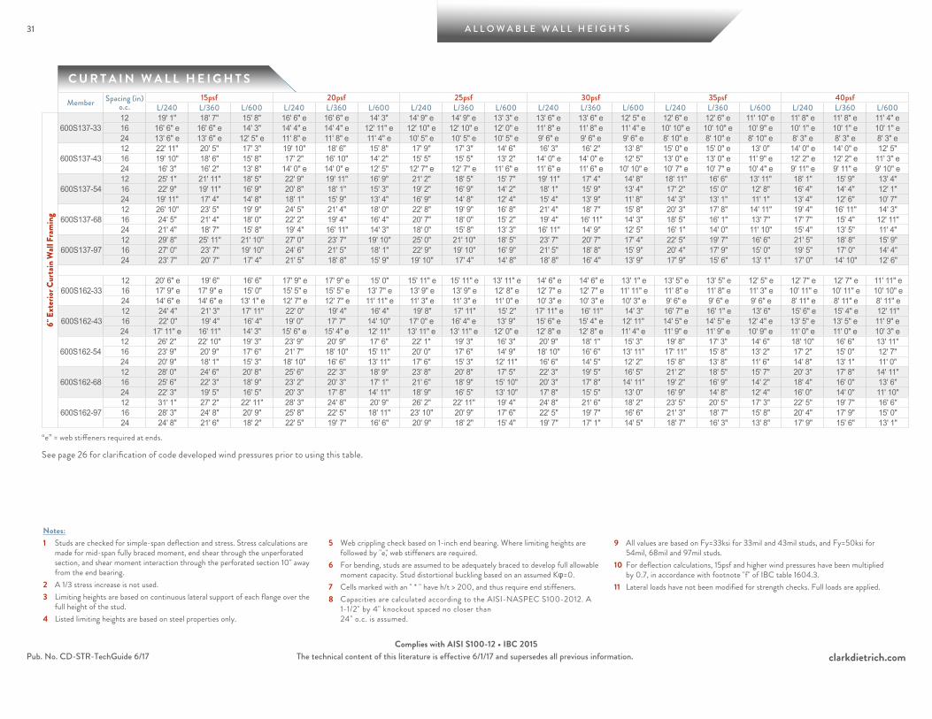
31 A L L O W A B L E W A L L H E I G H T S
clarkdietrich.comThe technical content of this literature is effective 6/1/17 and supersedes all previous information.Pub. No. CD-STR-TechGuide 6/17Complies with AISI S100-12 • IBC 2015
C U R T A I N W A L L H E I G H T S
Notes:1 Studs are checked for simple-span deflection and stress. Stress calculations are
made for mid-span fully braced moment, end shear through the unperforated section, and shear moment interaction through the perforated section 10" away from the end bearing.
2 A 1/3 stress increase is not used.3 Limiting heights are based on continuous lateral support of each flange over the
full height of the stud.4 Listed limiting heights are based on steel properties only.
5 Web crippling check based on 1-inch end bearing. Where limiting heights are followed by "e," web stiffeners are required.
6 For bending, studs are assumed to be adequately braced to develop full allowable moment capacity. Stud distortional buckling based on an assumed Kφ=0.
7 Cells marked with an " * " have h/t > 200, and thus require end stiffeners.8 Capacities are calculated according to the AISI-NASPEC S100-2012. A
1-1/2" by 4" knockout spaced no closer than 24" o.c. is assumed.
9 All values are based on Fy=33ksi for 33mil and 43mil studs, and Fy=50ksi for 54mil, 68mil and 97mil studs.
10 For deflection calculations, 15psf and higher wind pressures have been multiplied by 0.7, in accordance with footnote "f" of IBC table 1604.3.
11 Lateral loads have not been modified for strength checks. Full loads are applied.
Member Spacing (in) o.c.
15psf 20psf 25psf 30psf 35psf 40psfL/240 L/360 L/600 L/240 L/360 L/600 L/240 L/360 L/600 L/240 L/360 L/600 L/240 L/360 L/600 L/240 L/360 L/600
6" E
xter
ior C
urta
in W
all F
ram
ing
600S137-3312 19' 1" 18' 7" 15' 8" 16' 6" e 16' 6" e 14' 3" 14' 9" e 14' 9" e 13' 3" e 13' 6" e 13' 6" e 12' 5" e 12' 6" e 12' 6" e 11' 10" e 11' 8" e 11' 8" e 11' 4" e16 16' 6" e 16' 6" e 14' 3" 14' 4" e 14' 4" e 12' 11" e 12' 10" e 12' 10" e 12' 0" e 11' 8" e 11' 8" e 11' 4" e 10' 10" e 10' 10" e 10' 9" e 10' 1" e 10' 1" e 10' 1" e24 13' 6" e 13' 6" e 12' 5" e 11' 8" e 11' 8" e 11' 4" e 10' 5" e 10' 5" e 10' 5" e 9' 6" e 9' 6" e 9' 6" e 8' 10" e 8' 10" e 8' 10" e 8' 3" e 8' 3" e 8' 3" e
600S137-4312 22' 11" 20' 5" 17' 3" 19' 10" 18' 6" 15' 8" 17' 9" 17' 3" 14' 6" 16' 3" 16' 2" 13' 8" 15' 0" e 15' 0" e 13' 0" 14' 0" e 14' 0" e 12' 5" 16 19' 10" 18' 6" 15' 8" 17' 2" 16' 10" 14' 2" 15' 5" 15' 5" 13' 2" 14' 0" e 14' 0" e 12' 5" 13' 0" e 13' 0" e 11' 9" e 12' 2" e 12' 2" e 11' 3" e24 16' 3" 16' 2" 13' 8" 14' 0" e 14' 0" e 12' 5" 12' 7" e 12' 7" e 11' 6" e 11' 6" e 11' 6" e 10' 10" e 10' 7" e 10' 7" e 10' 4" e 9' 11" e 9' 11" e 9' 10" e
600S137-5412 25' 1" 21' 11" 18' 5" 22' 9" 19' 11" 16' 9" 21' 2" 18' 5" 15' 7" 19' 11" 17' 4" 14' 8" 18' 11" 16' 6" 13' 11" 18' 1" 15' 9" 13' 4" 16 22' 9" 19' 11" 16' 9" 20' 8" 18' 1" 15' 3" 19' 2" 16' 9" 14' 2" 18' 1" 15' 9" 13' 4" 17' 2" 15' 0" 12' 8" 16' 4" 14' 4" 12' 1" 24 19' 11" 17' 4" 14' 8" 18' 1" 15' 9" 13' 4" 16' 9" 14' 8" 12' 4" 15' 4" 13' 9" 11' 8" 14' 3" 13' 1" 11' 1" 13' 4" 12' 6" 10' 7"
600S137-6812 26' 10" 23' 5" 19' 9" 24' 5" 21' 4" 18' 0" 22' 8" 19' 9" 16' 8" 21' 4" 18' 7" 15' 8" 20' 3" 17' 8" 14' 11" 19' 4" 16' 11" 14' 3" 16 24' 5" 21' 4" 18' 0" 22' 2" 19' 4" 16' 4" 20' 7" 18' 0" 15' 2" 19' 4" 16' 11" 14' 3" 18' 5" 16' 1" 13' 7" 17' 7" 15' 4" 12' 11" 24 21' 4" 18' 7" 15' 8" 19' 4" 16' 11" 14' 3" 18' 0" 15' 8" 13' 3" 16' 11" 14' 9" 12' 5" 16' 1" 14' 0" 11' 10" 15' 4" 13' 5" 11' 4"
600S137-9712 29' 8" 25' 11" 21' 10" 27' 0" 23' 7" 19' 10" 25' 0" 21' 10" 18' 5" 23' 7" 20' 7" 17' 4" 22' 5" 19' 7" 16' 6" 21' 5" 18' 8" 15' 9" 16 27' 0" 23' 7" 19' 10" 24' 6" 21' 5" 18' 1" 22' 9" 19' 10" 16' 9" 21' 5" 18' 8" 15' 9" 20' 4" 17' 9" 15' 0" 19' 5" 17' 0" 14' 4" 24 23' 7" 20' 7" 17' 4" 21' 5" 18' 8" 15' 9" 19' 10" 17' 4" 14' 8" 18' 8" 16' 4" 13' 9" 17' 9" 15' 6" 13' 1" 17' 0" 14' 10" 12' 6"
600S162-3312 20' 6" e 19' 6" 16' 6" 17' 9" e 17' 9" e 15' 0" 15' 11" e 15' 11" e 13' 11" e 14' 6" e 14' 6" e 13' 1" e 13' 5" e 13' 5" e 12' 5" e 12' 7" e 12' 7" e 11' 11" e16 17' 9" e 17' 9" e 15' 0" 15' 5" e 15' 5" e 13' 7" e 13' 9" e 13' 9" e 12' 8" e 12' 7" e 12' 7" e 11' 11" e 11' 8" e 11' 8" e 11' 3" e 10' 11" e 10' 11" e 10' 10" e24 14' 6" e 14' 6" e 13' 1" e 12' 7" e 12' 7" e 11' 11" e 11' 3" e 11' 3" e 11' 0" e 10' 3" e 10' 3" e 10' 3" e 9' 6" e 9' 6" e 9' 6" e 8' 11" e 8' 11" e 8' 11" e
600S162-4312 24' 4" 21' 3" 17' 11" 22' 0" 19' 4" 16' 4" 19' 8" 17' 11" 15' 2" 17' 11" e 16' 11" 14' 3" 16' 7" e 16' 1" e 13' 6" 15' 6" e 15' 4" e 12' 11" 16 22' 0" 19' 4" 16' 4" 19' 0" 17' 7" 14' 10" 17' 0" e 16' 4" e 13' 9" 15' 6" e 15' 4" e 12' 11" 14' 5" e 14' 5" e 12' 4" e 13' 5" e 13' 5" e 11' 9" e24 17' 11" e 16' 11" 14' 3" 15' 6" e 15' 4" e 12' 11" 13' 11" e 13' 11" e 12' 0" e 12' 8" e 12' 8" e 11' 4" e 11' 9" e 11' 9" e 10' 9" e 11' 0" e 11' 0" e 10' 3" e
600S162-5412 26' 2" 22' 10" 19' 3" 23' 9" 20' 9" 17' 6" 22' 1" 19' 3" 16' 3" 20' 9" 18' 1" 15' 3" 19' 8" 17' 3" 14' 6" 18' 10" 16' 6" 13' 11" 16 23' 9" 20' 9" 17' 6" 21' 7" 18' 10" 15' 11" 20' 0" 17' 6" 14' 9" 18' 10" 16' 6" 13' 11" 17' 11" 15' 8" 13' 2" 17' 2" 15' 0" 12' 7" 24 20' 9" 18' 1" 15' 3" 18' 10" 16' 6" 13' 11" 17' 6" 15' 3" 12' 11" 16' 6" 14' 5" 12' 2" 15' 8" 13' 8" 11' 6" 14' 8" 13' 1" 11' 0"
600S162-6812 28' 0" 24' 6" 20' 8" 25' 6" 22' 3" 18' 9" 23' 8" 20' 8" 17' 5" 22' 3" 19' 5" 16' 5" 21' 2" 18' 5" 15' 7" 20' 3" 17' 8" 14' 11" 16 25' 6" 22' 3" 18' 9" 23' 2" 20' 3" 17' 1" 21' 6" 18' 9" 15' 10" 20' 3" 17' 8" 14' 11" 19' 2" 16' 9" 14' 2" 18' 4" 16' 0" 13' 6" 24 22' 3" 19' 5" 16' 5" 20' 3" 17' 8" 14' 11" 18' 9" 16' 5" 13' 10" 17' 8" 15' 5" 13' 0" 16' 9" 14' 8" 12' 4" 16' 0" 14' 0" 11' 10"
600S162-9712 31' 1" 27' 2" 22' 11" 28' 3" 24' 8" 20' 9" 26' 2" 22' 11" 19' 4" 24' 8" 21' 6" 18' 2" 23' 5" 20' 5" 17' 3" 22' 5" 19' 7" 16' 6" 16 28' 3" 24' 8" 20' 9" 25' 8" 22' 5" 18' 11" 23' 10" 20' 9" 17' 6" 22' 5" 19' 7" 16' 6" 21' 3" 18' 7" 15' 8" 20' 4" 17' 9" 15' 0" 24 24' 8" 21' 6" 18' 2" 22' 5" 19' 7" 16' 6" 20' 9" 18' 2" 15' 4" 19' 7" 17' 1" 14' 5" 18' 7" 16' 3" 13' 8" 17' 9" 15' 6" 13' 1"
“e” = web stiffeners required at ends.
See page 26 for clarification of code developed wind pressures prior to using this table.

A L L O W A B L E W A L L H E I G H T S
clarkdietrich.comThe technical content of this literature is effective 6/1/17 and supersedes all previous information.
32
Pub. No. CD-STR-TechGuide 6/17Complies with AISI S100-12 • IBC 2015
C U R T A I N W A L L H E I G H T S
32
Notes:1 Studs are checked for simple-span deflection and stress. Stress calculations are
made for mid-span fully braced moment, end shear through the unperforated section, and shear moment interaction through the perforated section 10" away from the end bearing.
2 A 1/3 stress increase is not used.3 Limiting heights are based on continuous lateral support of each flange over the
full height of the stud.4 Listed limiting heights are based on steel properties only.
5 Web crippling check based on 1-inch end bearing. Where limiting heights are followed by "e," web stiffeners are required.
6 For bending, studs are assumed to be adequately braced to develop full allowable moment capacity. Stud distortional buckling based on an assumed Kφ=0.
7 Cells marked with an " * " have h/t > 200, and thus require end stiffeners.8 Capacities are calculated according to the AISI-NASPEC S100-2012. A
1-1/2" by 4" knockout spaced no closer than 24" o.c. is assumed.
9 All values are based on Fy=33ksi for 33mil and 43mil studs, and Fy=50ksi for 54mil, 68mil and 97mil studs.
10 For deflection calculations, 15psf and higher wind pressures have been multiplied by 0.7, in accordance with footnote "f" of IBC table 1604.3.
11 Lateral loads have not been modified for strength checks. Full loads are applied.
Member Spacing (in) o.c.
15psf 20psf 25psf 30psf 35psf 40psfL/240 L/360 L/600 L/240 L/360 L/600 L/240 L/360 L/600 L/240 L/360 L/600 L/240 L/360 L/600 L/240 L/360 L/600
6" E
xter
ior C
urta
in W
all F
ram
ing
600S200-3312 21' 11" e 20' 6" e 17' 3" 18' 11" e 18' 7" e 15' 8" e 16' 11" e 16' 11" e 14' 7" e 15' 6" e 15' 6" e 13' 8" e 14' 4" e 14' 4" e 13' 0" e 13' 5" e 13' 5" e 12' 5" e16 18' 11" e 18' 7" e 15' 8" e 16' 5" e 16' 5" e 14' 3" e 14' 8" e 14' 8" e 13' 3" e 13' 5" e 13' 5" e 12' 5" e 12' 5" e 12' 5" e 11' 10" e 11' 7" e 11' 7" e 11' 4" e24 15' 6" e 15' 6" e 13' 8" e 13' 5" e 13' 5" e 12' 5" e 12' 0" e 12' 0" e 11' 7" e 10' 11" e 10' 11" e 10' 10" e 10' 2" e 10' 2" e 10' 2" e 9' 6" e 9' 6" e 9' 6" e
600S200-4312 25' 7" 22' 4" 18' 10" 22' 8" 20' 4" 17' 2" 20' 3" 18' 10" 15' 11" 18' 6" e 17' 9" e 15' 0" 17' 1" e 16' 10" e 14' 3" 16' 0" e 16' 0" e 13' 7" e16 22' 8" 20' 4" 17' 2" 19' 7" e 18' 5" 15' 7" 17' 7" e 17' 2" e 14' 5" 16' 0" e 16' 0" e 13' 7" e 14' 10" e 14' 10" e 12' 11" e 13' 10" e 13' 10" e 12' 4" e24 18' 6" e 17' 9" e 15' 0" 16' 0" e 16' 0" e 13' 7" e 14' 4" e 14' 4" e 12' 7" e 13' 1" e 13' 1" e 11' 11" e 12' 1" e 12' 1" e 11' 3" e 11' 4" e 11' 4" e 10' 9" e
600S200-5412 27' 6" 24' 0" 20' 3" 24' 11" 21' 10" 18' 5" 23' 2" 20' 3" 17' 1" 21' 10" 19' 1" 16' 1" 20' 9" 18' 1" 15' 3" 19' 10" 17' 4" 14' 7" 16 24' 11" 21' 10" 18' 5" 22' 8" 19' 10" 16' 8" 21' 1" 18' 5" 15' 6" 19' 10" 17' 4" 14' 7" 18' 10" 16' 5" 13' 10" 18' 0" 15' 9" 13' 3" 24 21' 10" 19' 1" 16' 1" 19' 10" 17' 4" 14' 7" 18' 5" 16' 1" 13' 7" 17' 4" 15' 1" 12' 9" 16' 2" 14' 4" 12' 1" 15' 1" e 13' 9" 11' 7"
600S200-6812 29' 6" 25' 9" 21' 9" 26' 9" 23' 5" 19' 9" 24' 10" 21' 9" 18' 4" 23' 5" 20' 5" 17' 3" 22' 3" 19' 5" 16' 4" 21' 3" 18' 7" 15' 8" 16 26' 9" 23' 5" 19' 9" 24' 4" 21' 3" 17' 11" 22' 7" 19' 9" 16' 8" 21' 3" 18' 7" 15' 8" 20' 2" 17' 8" 14' 11" 19' 4" 16' 10" 14' 3" 24 23' 5" 20' 5" 17' 3" 21' 3" 18' 7" 15' 8" 19' 9" 17' 3" 14' 6" 18' 7" 16' 3" 13' 8" 17' 8" 15' 5" 13' 0" 16' 10" 14' 9" 12' 5"
600S200-9712 32' 9" 28' 7" 24' 1" 29' 9" 26' 0" 21' 11" 27' 7" 24' 1" 20' 4" 26' 0" 22' 8" 19' 2" 24' 8" 21' 7" 18' 2" 23' 7" 20' 7" 17' 5" 16 29' 9" 26' 0" 21' 11" 27' 0" 23' 7" 19' 11" 25' 1" 21' 11" 18' 6" 23' 7" 20' 7" 17' 5" 22' 5" 19' 7" 16' 6" 21' 5" 18' 9" 15' 10" 24 26' 0" 22' 8" 19' 2" 23' 7" 20' 7" 17' 5" 21' 11" 19' 2" 16' 2" 20' 7" 18' 0" 15' 2" 19' 7" 17' 1" 14' 5" 18' 9" 16' 4" 13' 10"
600S250-4312 26' 10" 23' 5" 19' 9" 23' 3" 21' 3" 17' 11" 20' 10" e 19' 9" 16' 8" 19' 0" e 18' 7" e 15' 8" 17' 7" e 17' 7" e 14' 11" e 16' 5" e 16' 5" e 14' 3" e16 23' 3" 21' 3" 17' 11" 20' 2" e 19' 4" 16' 4" 18' 0" e 17' 11" e 15' 2" 16' 5" e 16' 5" e 14' 3" e 15' 3" e 15' 3" e 13' 6" e 14' 3" e 14' 3" e 12' 11" e24 19' 0" e 18' 7" e 15' 8" 16' 5" e 16' 5" e 14' 3" e 14' 8" e 14' 8" e 13' 3" e 13' 5" e 13' 5" e 12' 5" e 12' 5" e 12' 5" e 11' 10" e 11' 7" e 11' 7" e 11' 4" e
600S250-5412 28' 8" 25' 0" 21' 1" 26' 0" 22' 9" 19' 2" 24' 2" 21' 1" 17' 10" 22' 9" 19' 10" 16' 9" 21' 7" 18' 10" 15' 11" 20' 8" 18' 1" 15' 3" 16 26' 0" 22' 9" 19' 2" 23' 8" 20' 8" 17' 5" 21' 11" 19' 2" 16' 2" 20' 8" 18' 1" 15' 3" 19' 7" 17' 2" 14' 6" 18' 9" 16' 5" 13' 10" 24 22' 9" 19' 10" 16' 9" 20' 8" 18' 1" 15' 3" 19' 2" 16' 9" 14' 2" 17' 10" 15' 9" 13' 4" 16' 6" 15' 0" 12' 8" 15' 6" e 14' 4" 12' 1"
600S250-6812 30' 11" 27' 0" 22' 9" 28' 1" 24' 6" 20' 8" 26' 1" 22' 9" 19' 2" 24' 6" 21' 5" 18' 1" 23' 4" 20' 4" 17' 2" 22' 3" 19' 6" 16' 5" 16 28' 1" 24' 6" 20' 8" 25' 6" 22' 3" 18' 10" 23' 8" 20' 8" 17' 5" 22' 3" 19' 6" 16' 5" 21' 2" 18' 6" 15' 7" 20' 3" 17' 8" 14' 11" 24 24' 6" 21' 5" 18' 1" 22' 3" 19' 6" 16' 5" 20' 8" 18' 1" 15' 3" 19' 6" 17' 0" 14' 4" 18' 6" 16' 2" 13' 7" 17' 8" 15' 5" 13' 0"
600S250-9712 34' 4" 30' 0" 25' 4" 31' 3" 27' 3" 23' 0" 29' 0" 25' 4" 21' 4" 27' 3" 23' 10" 20' 1" 25' 11" 22' 8" 19' 1" 24' 9" 21' 8" 18' 3" 16 31' 3" 27' 3" 23' 0" 28' 4" 24' 9" 20' 11" 26' 4" 23' 0" 19' 5" 24' 9" 21' 8" 18' 3" 23' 6" 20' 7" 17' 4" 22' 6" 19' 8" 16' 7" 24 27' 3" 23' 10" 20' 1" 24' 9" 21' 8" 18' 3" 23' 0" 20' 1" 16' 11" 21' 8" 18' 11" 15' 11" 20' 7" 18' 0" 15' 2" 19' 8" 17' 2" 14' 6"
600S300-5412 29' 3" 25' 7" 21' 7" 26' 7" 23' 3" 19' 7" 24' 8" 21' 7" 18' 2" 23' 3" 20' 3" 17' 1" 22' 1" 19' 3" 16' 3" 21' 1" 18' 5" 15' 7" 16 26' 7" 23' 3" 19' 7" 24' 2" 21' 1" 17' 10" 22' 5" 19' 7" 16' 6" 21' 1" 18' 5" 15' 7" 20' 1" 17' 6" 14' 9" 19' 2" 16' 9" 14' 2" 24 23' 3" 20' 3" 17' 1" 21' 1" 18' 5" 15' 7" 19' 7" 17' 1" 14' 5" 18' 2" 16' 1" 13' 7" 16' 10" 15' 4" 12' 11" 15' 9" e 14' 8" 12' 4"
600S300-6812 31' 11" 27' 11" 23' 6" 29' 0" 25' 4" 21' 5" 26' 11" 23' 6" 19' 10" 25' 4" 22' 2" 18' 8" 24' 1" 21' 0" 17' 9" 23' 0" 20' 2" 17' 0" 16 29' 0" 25' 4" 21' 5" 26' 4" 23' 0" 19' 5" 24' 6" 21' 5" 18' 0" 23' 0" 20' 2" 17' 0" 21' 11" 19' 1" 16' 1" 20' 11" 18' 3" 15' 5" 24 25' 4" 22' 2" 18' 8" 23' 0" 20' 2" 17' 0" 21' 5" 18' 8" 15' 9" 20' 2" 17' 7" 14' 10" 19' 1" 16' 8" 14' 1" 18' 3" 16' 0" 13' 6"
600S300-9712 35' 8" 31' 2" 26' 4" 32' 5" 28' 4" 23' 11" 30' 1" 26' 4" 22' 2" 28' 4" 24' 9" 20' 10" 26' 11" 23' 6" 19' 10" 25' 9" 22' 6" 19' 0" 16 32' 5" 28' 4" 23' 11" 29' 6" 25' 9" 21' 8" 27' 4" 23' 11" 20' 2" 25' 9" 22' 6" 19' 0" 24' 5" 21' 4" 18' 0" 23' 5" 20' 5" 17' 3" 24 28' 4" 24' 9" 20' 10" 25' 9" 22' 6" 19' 0" 23' 11" 20' 10" 17' 7" 22' 6" 19' 8" 16' 7" 21' 4" 18' 8" 15' 9" 20' 5" 17' 10" 15' 1"
“e” = web stiffeners required at ends. See page 26 for clarification of code developed wind pressures prior to using this table.

33 A L L O W A B L E W A L L H E I G H T S
clarkdietrich.comThe technical content of this literature is effective 6/1/17 and supersedes all previous information.Pub. No. CD-STR-TechGuide 6/17Complies with AISI S100-12 • IBC 2015
C U R T A I N W A L L H E I G H T S
Notes:1 Studs are checked for simple-span deflection and stress. Stress calculations are
made for mid-span fully braced moment, end shear through the unperforated section, and shear moment interaction through the perforated section 10" away from the end bearing.
2 A 1/3 stress increase is not used.3 Limiting heights are based on continuous lateral support of each flange over the
full height of the stud.4 Listed limiting heights are based on steel properties only.
5 Web crippling check based on 1-inch end bearing. Where limiting heights are followed by "e," web stiffeners are required.
6 For bending, studs are assumed to be adequately braced to develop full allowable moment capacity. Stud distortional buckling based on an assumed Kφ=0.
7 Cells marked with an " * " have h/t > 200, and thus require end stiffeners.8 Capacities are calculated according to the AISI-NASPEC S100-2012. A
1-1/2" by 4" knockout spaced no closer than 24" o.c. is assumed.
9 All values are based on Fy=33ksi for 33mil and 43mil studs, and Fy=50ksi for 54mil, 68mil and 97mil studs.
10 For deflection calculations, 15psf and higher wind pressures have been multiplied by 0.7, in accordance with footnote "f" of IBC table 1604.3.
11 Lateral loads have not been modified for strength checks. Full loads are applied.
Member Spacing (in) o.c.
15psf 20psf 25psf 30psf 35psf 40psfL/240 L/360 L/600 L/240 L/360 L/600 L/240 L/360 L/600 L/240 L/360 L/600 L/240 L/360 L/600 L/240 L/360 L/600
8" E
xter
ior C
urta
in W
all F
ram
ing
800S137-3312 21' 10" e 21' 10" e 19' 7" e 18' 11" e 18' 11" e 17' 9" e 16' 11" e 16' 11" e 16' 6" e 15' 5" e 15' 5" e 15' 5" e 14' 3" e 14' 3" e 14' 3" e 13' 4" e 13' 4" e 13' 4" e16 18' 11" e 18' 11" e 17' 9" e 16' 4" e 16' 4" e 16' 2" e 14' 8" e 14' 8" e 14' 8" e 13' 4" e 13' 4" e 13' 4" e 12' 4" e 12' 4" e 12' 4" e 11' 7" e 11' 7" e 11' 7" e24 15' 5" e 15' 5" e 15' 5" e 13' 4" e 13' 4" e 13' 4" e 11' 11" e 11' 11" e 11' 11" e 10' 11" e 10' 11" e 10' 11" e 10' 1" e 10' 1" e 10' 1" e 9' 5" e 9' 5" e 9' 5" e
800S137-4312 26' 6" 25' 6" 21' 6" 22' 11" 22' 11" 19' 7" 20' 6" e 20' 6" e 18' 2" 18' 9" e 18' 9" e 17' 1" e 17' 4" e 17' 4" e 16' 3" e 16' 3" e 16' 3" e 15' 6" e16 22' 11" 22' 11" 19' 7" 19' 10" e 19' 10" e 17' 9" 17' 9" e 17' 9" e 16' 6" e 16' 3" e 16' 3" e 15' 6" e 15' 0" e 15' 0" e 14' 9" e 14' 1" e 14' 1" e 14' 1" e24 18' 9" e 18' 9" e 17' 1" e 16' 3" e 16' 3" e 15' 6" e 14' 6" e 14' 6" e 14' 5" e 13' 3" e 13' 3" e 13' 3" e 12' 3" e 12' 3" e 12' 3" e 11' 6" e 11' 6" e 11' 6" e
800S137-5412 31' 5" 27' 6" 23' 2" 28' 7" 24' 11" 21' 1" 26' 6" 23' 2" 19' 6" 24' 11" 21' 10" 18' 5" 23' 4" 20' 8" 17' 6" 21' 9" 19' 10" 16' 8" 16 28' 7" 24' 11" 21' 1" 25' 11" 22' 8" 19' 1" 23' 10" 21' 1" 17' 9" 21' 9" 19' 10" 16' 8" 20' 2" 18' 10" 15' 10" 18' 10" 18' 0" 15' 2" 24 24' 11" 21' 10" 18' 5" 21' 9" 19' 10" 16' 8" 19' 6" 18' 5" 15' 6" 17' 9" 17' 4" 14' 7" 16' 6" e 16' 5" e 13' 10" 15' 5" e 15' 5" e 13' 3"
800S137-6812 34' 0" 29' 8" 25' 0" 30' 11" 27' 0" 22' 9" 28' 8" 25' 0" 21' 1" 27' 0" 23' 7" 19' 10" 25' 7" 22' 5" 18' 11" 24' 6" 21' 5" 18' 1" 16 30' 11" 27' 0" 22' 9" 28' 1" 24' 6" 20' 8" 26' 0" 22' 9" 19' 2" 24' 6" 21' 5" 18' 1" 23' 3" 20' 4" 17' 2" 22' 3" 19' 5" 16' 5" 24 27' 0" 23' 7" 19' 10" 24' 6" 21' 5" 18' 1" 22' 9" 19' 10" 16' 9" 21' 0" 18' 8" 15' 9" 19' 5" 17' 9" 15' 0" 18' 2" 17' 0" 14' 4"
800S137-9712 37' 9" 32' 11" 27' 10" 34' 3" 29' 11" 25' 3" 31' 10" 27' 10" 23' 5" 29' 11" 26' 2" 22' 1" 28' 5" 24' 10" 20' 11" 27' 2" 23' 9" 20' 1" 16 34' 3" 29' 11" 25' 3" 31' 2" 27' 2" 22' 11" 28' 11" 25' 3" 21' 4" 27' 2" 23' 9" 20' 1" 25' 10" 22' 7" 19' 0" 24' 9" 21' 7" 18' 3" 24 29' 11" 26' 2" 22' 1" 27' 2" 23' 9" 20' 1" 25' 3" 22' 1" 18' 7" 23' 9" 20' 9" 17' 6" 22' 7" 19' 9" 16' 8" 21' 7" 18' 10" 15' 11"
800S162-3312 23' 8" e 23' 8" e 20' 4" e 20' 6" e 20' 6" e 18' 6" e 18' 4" e 18' 4" e 17' 2" e 16' 9" e 16' 9" e 16' 2" e 15' 6" e 15' 6" e 15' 4" e 14' 6" e 14' 6" e 14' 6" e16 20' 6" e 20' 6" e 18' 6" e 17' 9" e 17' 9" e 16' 10" e 15' 11" e 15' 11" e 15' 7" e 14' 6" e 14' 6" e 14' 6" e 13' 5" e 13' 5" e 13' 5" e 12' 7" e 12' 7" e 12' 7" e24 16' 9" e 16' 9" e 16' 2" e 14' 6" e 14' 6" e 14' 6" e 13' 0" e 13' 0" e 13' 0" e 11' 10" e 11' 10" e 11' 10" e 11' 0" e 11' 0" e 11' 0" e 10' 3" e 10' 3" e 10' 3" e
800S162-4312 28' 7" 26' 7" 22' 5" 24' 9" e 24' 2" 20' 4" 22' 1" e 22' 1" e 18' 11" 20' 2" e 20' 2" e 17' 9" e 18' 8" e 18' 8" e 16' 11" e 17' 6" e 17' 6" e 16' 2" e16 24' 9" e 24' 2" 20' 4" 21' 5" e 21' 5" e 18' 6" 19' 2" e 19' 2" e 17' 2" e 17' 6" e 17' 6" e 16' 2" e 16' 2" e 16' 2" e 15' 4" e 15' 2" e 15' 2" e 14' 8" e24 20' 2" e 20' 2" e 17' 9" e 17' 6" e 17' 6" e 16' 2" e 15' 8" e 15' 8" e 15' 0" e 14' 3" e 14' 3" e 14' 1" e 13' 3" e 13' 3" e 13' 3" e 12' 4" e 12' 4" e 12' 4" e
800S162-5412 32' 8" 28' 7" 24' 1" 29' 9" 25' 11" 21' 11" 27' 7" 24' 1" 20' 4" 25' 11" 22' 8" 19' 1" 24' 8" 21' 6" 18' 2" 23' 5" 20' 7" 17' 4" 16 29' 9" 25' 11" 21' 11" 27' 0" 23' 7" 19' 11" 25' 1" 21' 11" 18' 6" 23' 5" 20' 7" 17' 4" 21' 8" 19' 7" 16' 6" 20' 3" 18' 9" 15' 9" 24 25' 11" 22' 8" 19' 1" 23' 5" 20' 7" 17' 4" 20' 11" 19' 1" 16' 2" 19' 1" 18' 0" 15' 2" 17' 8" e 17' 1" e 14' 5" 16' 6" e 16' 4" e 13' 9"
800S162-6812 35' 4" 30' 10" 26' 0" 32' 1" 28' 1" 23' 8" 29' 10" 26' 0" 22' 0" 28' 1" 24' 6" 20' 8" 26' 8" 23' 3" 19' 8" 25' 6" 22' 3" 18' 9" 16 32' 1" 28' 1" 23' 8" 29' 2" 25' 6" 21' 6" 27' 1" 23' 8" 19' 11" 25' 6" 22' 3" 18' 9" 24' 3" 21' 2" 17' 10" 23' 2" 20' 3" 17' 1" 24 28' 1" 24' 6" 20' 8" 25' 6" 22' 3" 18' 9" 23' 8" 20' 8" 17' 5" 22' 3" 19' 5" 16' 5" 20' 9" 18' 6" 15' 7" 19' 5" 17' 8" 14' 11"
800S162-9712 39' 3" 34' 4" 28' 11" 35' 8" 31' 2" 26' 4" 33' 2" 28' 11" 24' 5" 31' 2" 27' 3" 23' 0" 29' 7" 25' 11" 21' 10" 28' 4" 24' 9" 20' 11" 16 35' 8" 31' 2" 26' 4" 32' 5" 28' 4" 23' 11" 30' 1" 26' 4" 22' 2" 28' 4" 24' 9" 20' 11" 26' 11" 23' 6" 19' 10" 25' 9" 22' 6" 19' 0" 24 31' 2" 27' 3" 23' 0" 28' 4" 24' 9" 20' 11" 26' 4" 23' 0" 19' 5" 24' 9" 21' 7" 18' 3" 23' 6" 20' 6" 17' 4" 22' 6" 19' 8" 16' 7"
“e” = web stiffeners required at ends.
See page 26 for clarification of code developed wind pressures prior to using this table.
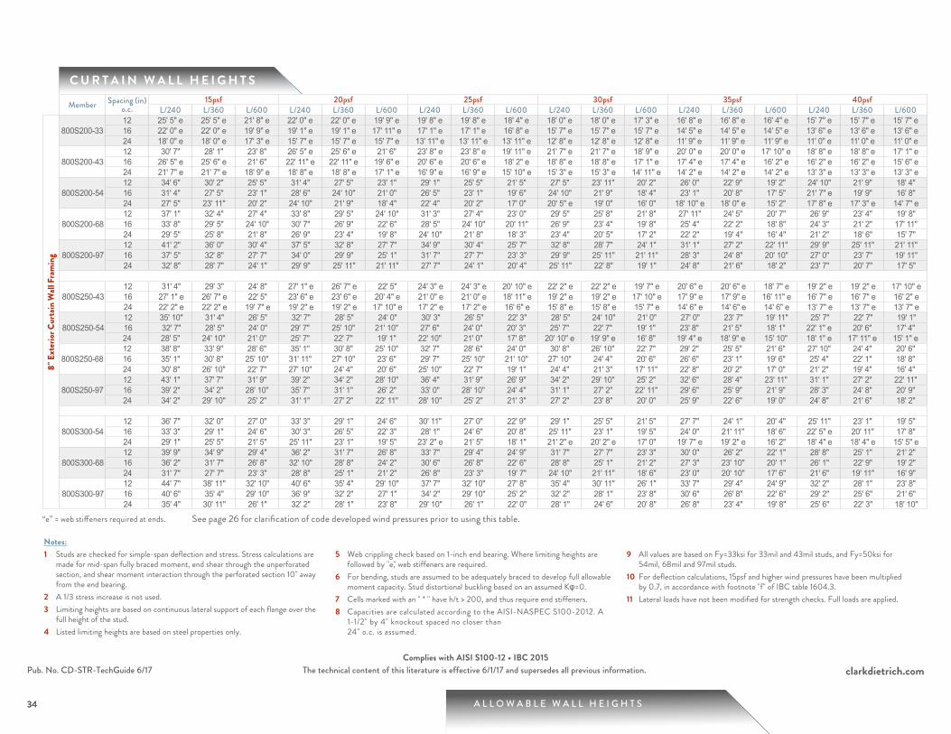
A L L O W A B L E W A L L H E I G H T S
clarkdietrich.comThe technical content of this literature is effective 6/1/17 and supersedes all previous information.
34
Pub. No. CD-STR-TechGuide 6/17Complies with AISI S100-12 • IBC 2015
C U R T A I N W A L L H E I G H T S
34
Notes:1 Studs are checked for simple-span deflection and stress. Stress calculations are
made for mid-span fully braced moment, end shear through the unperforated section, and shear moment interaction through the perforated section 10" away from the end bearing.
2 A 1/3 stress increase is not used.3 Limiting heights are based on continuous lateral support of each flange over the
full height of the stud.4 Listed limiting heights are based on steel properties only.
5 Web crippling check based on 1-inch end bearing. Where limiting heights are followed by "e," web stiffeners are required.
6 For bending, studs are assumed to be adequately braced to develop full allowable moment capacity. Stud distortional buckling based on an assumed Kφ=0.
7 Cells marked with an " * " have h/t > 200, and thus require end stiffeners.8 Capacities are calculated according to the AISI-NASPEC S100-2012. A
1-1/2" by 4" knockout spaced no closer than 24" o.c. is assumed.
9 All values are based on Fy=33ksi for 33mil and 43mil studs, and Fy=50ksi for 54mil, 68mil and 97mil studs.
10 For deflection calculations, 15psf and higher wind pressures have been multiplied by 0.7, in accordance with footnote "f" of IBC table 1604.3.
11 Lateral loads have not been modified for strength checks. Full loads are applied.
Member Spacing (in) o.c.
15psf 20psf 25psf 30psf 35psf 40psfL/240 L/360 L/600 L/240 L/360 L/600 L/240 L/360 L/600 L/240 L/360 L/600 L/240 L/360 L/600 L/240 L/360 L/600
8" E
xter
ior C
urta
in W
all F
ram
ing
800S200-3312 25' 5" e 25' 5" e 21' 8" e 22' 0" e 22' 0" e 19' 9" e 19' 8" e 19' 8" e 18' 4" e 18' 0" e 18' 0" e 17' 3" e 16' 8" e 16' 8" e 16' 4" e 15' 7" e 15' 7" e 15' 7" e16 22' 0" e 22' 0" e 19' 9" e 19' 1" e 19' 1" e 17' 11" e 17' 1" e 17' 1" e 16' 8" e 15' 7" e 15' 7" e 15' 7" e 14' 5" e 14' 5" e 14' 5" e 13' 6" e 13' 6" e 13' 6" e24 18' 0" e 18' 0" e 17' 3" e 15' 7" e 15' 7" e 15' 7" e 13' 11" e 13' 11" e 13' 11" e 12' 8" e 12' 8" e 12' 8" e 11' 9" e 11' 9" e 11' 9" e 11' 0" e 11' 0" e 11' 0" e
800S200-4312 30' 7" 28' 1" 23' 8" 26' 5" e 25' 6" e 21' 6" 23' 8" e 23' 8" e 19' 11" e 21' 7" e 21' 7" e 18' 9" e 20' 0" e 20' 0" e 17' 10" e 18' 8" e 18' 8" e 17' 1" e16 26' 5" e 25' 6" e 21' 6" 22' 11" e 22' 11" e 19' 6" e 20' 6" e 20' 6" e 18' 2" e 18' 8" e 18' 8" e 17' 1" e 17' 4" e 17' 4" e 16' 2" e 16' 2" e 16' 2" e 15' 6" e24 21' 7" e 21' 7" e 18' 9" e 18' 8" e 18' 8" e 17' 1" e 16' 9" e 16' 9" e 15' 10" e 15' 3" e 15' 3" e 14' 11" e 14' 2" e 14' 2" e 14' 2" e 13' 3" e 13' 3" e 13' 3" e
800S200-5412 34' 6" 30' 2" 25' 5" 31' 4" 27' 5" 23' 1" 29' 1" 25' 5" 21' 5" 27' 5" 23' 11" 20' 2" 26' 0" 22' 9" 19' 2" 24' 10" 21' 9" 18' 4" 16 31' 4" 27' 5" 23' 1" 28' 6" 24' 10" 21' 0" 26' 5" 23' 1" 19' 6" 24' 10" 21' 9" 18' 4" 23' 1" 20' 8" 17' 5" 21' 7" e 19' 9" 16' 8" 24 27' 5" 23' 11" 20' 2" 24' 10" 21' 9" 18' 4" 22' 4" 20' 2" 17' 0" 20' 5" e 19' 0" 16' 0" 18' 10" e 18' 0" e 15' 2" 17' 8" e 17' 3" e 14' 7" e
800S200-6812 37' 1" 32' 4" 27' 4" 33' 8" 29' 5" 24' 10" 31' 3" 27' 4" 23' 0" 29' 5" 25' 8" 21' 8" 27' 11" 24' 5" 20' 7" 26' 9" 23' 4" 19' 8" 16 33' 8" 29' 5" 24' 10" 30' 7" 26' 9" 22' 6" 28' 5" 24' 10" 20' 11" 26' 9" 23' 4" 19' 8" 25' 4" 22' 2" 18' 8" 24' 3" 21' 2" 17' 11" 24 29' 5" 25' 8" 21' 8" 26' 9" 23' 4" 19' 8" 24' 10" 21' 8" 18' 3" 23' 4" 20' 5" 17' 2" 22' 2" 19' 4" 16' 4" 21' 2" 18' 6" 15' 7"
800S200-9712 41' 2" 36' 0" 30' 4" 37' 5" 32' 8" 27' 7" 34' 9" 30' 4" 25' 7" 32' 8" 28' 7" 24' 1" 31' 1" 27' 2" 22' 11" 29' 9" 25' 11" 21' 11" 16 37' 5" 32' 8" 27' 7" 34' 0" 29' 9" 25' 1" 31' 7" 27' 7" 23' 3" 29' 9" 25' 11" 21' 11" 28' 3" 24' 8" 20' 10" 27' 0" 23' 7" 19' 11" 24 32' 8" 28' 7" 24' 1" 29' 9" 25' 11" 21' 11" 27' 7" 24' 1" 20' 4" 25' 11" 22' 8" 19' 1" 24' 8" 21' 6" 18' 2" 23' 7" 20' 7" 17' 5"
800S250-4312 31' 4" 29' 3" 24' 8" 27' 1" e 26' 7" e 22' 5" 24' 3" e 24' 3" e 20' 10" e 22' 2" e 22' 2" e 19' 7" e 20' 6" e 20' 6" e 18' 7" e 19' 2" e 19' 2" e 17' 10" e16 27' 1" e 26' 7" e 22' 5" 23' 6" e 23' 6" e 20' 4" e 21' 0" e 21' 0" e 18' 11" e 19' 2" e 19' 2" e 17' 10" e 17' 9" e 17' 9" e 16' 11" e 16' 7" e 16' 7" e 16' 2" e24 22' 2" e 22' 2" e 19' 7" e 19' 2" e 19' 2" e 17' 10" e 17' 2" e 17' 2" e 16' 6" e 15' 8" e 15' 8" e 15' 7" e 14' 6" e 14' 6" e 14' 6" e 13' 7" e 13' 7" e 13' 7" e
800S250-5412 35' 10" 31' 4" 26' 5" 32' 7" 28' 5" 24' 0" 30' 3" 26' 5" 22' 3" 28' 5" 24' 10" 21' 0" 27' 0" 23' 7" 19' 11" 25' 7" 22' 7" 19' 1" 16 32' 7" 28' 5" 24' 0" 29' 7" 25' 10" 21' 10" 27' 6" 24' 0" 20' 3" 25' 7" 22' 7" 19' 1" 23' 8" 21' 5" 18' 1" 22' 1" e 20' 6" 17' 4" 24 28' 5" 24' 10" 21' 0" 25' 7" 22' 7" 19' 1" 22' 10" 21' 0" 17' 8" 20' 10" e 19' 9" e 16' 8" 19' 4" e 18' 9" e 15' 10" 18' 1" e 17' 11" e 15' 1" e
800S250-6812 38' 8" 33' 9" 28' 6" 35' 1" 30' 8" 25' 10" 32' 7" 28' 6" 24' 0" 30' 8" 26' 10" 22' 7" 29' 2" 25' 5" 21' 6" 27' 10" 24' 4" 20' 6" 16 35' 1" 30' 8" 25' 10" 31' 11" 27' 10" 23' 6" 29' 7" 25' 10" 21' 10" 27' 10" 24' 4" 20' 6" 26' 6" 23' 1" 19' 6" 25' 4" 22' 1" 18' 8" 24 30' 8" 26' 10" 22' 7" 27' 10" 24' 4" 20' 6" 25' 10" 22' 7" 19' 1" 24' 4" 21' 3" 17' 11" 22' 8" 20' 2" 17' 0" 21' 2" 19' 4" 16' 4"
800S250-9712 43' 1" 37' 7" 31' 9" 39' 2" 34' 2" 28' 10" 36' 4" 31' 9" 26' 9" 34' 2" 29' 10" 25' 2" 32' 6" 28' 4" 23' 11" 31' 1" 27' 2" 22' 11" 16 39' 2" 34' 2" 28' 10" 35' 7" 31' 1" 26' 2" 33' 0" 28' 10" 24' 4" 31' 1" 27' 2" 22' 11" 29' 6" 25' 9" 21' 9" 28' 3" 24' 8" 20' 9" 24 34' 2" 29' 10" 25' 2" 31' 1" 27' 2" 22' 11" 28' 10" 25' 2" 21' 3" 27' 2" 23' 8" 20' 0" 25' 9" 22' 6" 19' 0" 24' 8" 21' 6" 18' 2"
800S300-5412 36' 7" 32' 0" 27' 0" 33' 3" 29' 1" 24' 6" 30' 11" 27' 0" 22' 9" 29' 1" 25' 5" 21' 5" 27' 7" 24' 1" 20' 4" 25' 11" 23' 1" 19' 5" 16 33' 3" 29' 1" 24' 6" 30' 3" 26' 5" 22' 3" 28' 1" 24' 6" 20' 8" 25' 11" 23' 1" 19' 5" 24' 0" 21' 11" 18' 6" 22' 5" e 20' 11" 17' 8" 24 29' 1" 25' 5" 21' 5" 25' 11" 23' 1" 19' 5" 23' 2" e 21' 5" 18' 1" 21' 2" e 20' 2" e 17' 0" 19' 7" e 19' 2" e 16' 2" 18' 4" e 18' 4" e 15' 5" e
800S300-6812 39' 9" 34' 9" 29' 4" 36' 2" 31' 7" 26' 8" 33' 7" 29' 4" 24' 9" 31' 7" 27' 7" 23' 3" 30' 0" 26' 2" 22' 1" 28' 8" 25' 1" 21' 2" 16 36' 2" 31' 7" 26' 8" 32' 10" 28' 8" 24' 2" 30' 6" 26' 8" 22' 6" 28' 8" 25' 1" 21' 2" 27' 3" 23' 10" 20' 1" 26' 1" 22' 9" 19' 2" 24 31' 7" 27' 7" 23' 3" 28' 8" 25' 1" 21' 2" 26' 8" 23' 3" 19' 7" 24' 10" 21' 11" 18' 6" 23' 0" 20' 10" 17' 6" 21' 6" 19' 11" 16' 9"
800S300-9712 44' 7" 38' 11" 32' 10" 40' 6" 35' 4" 29' 10" 37' 7" 32' 10" 27' 8" 35' 4" 30' 11" 26' 1" 33' 7" 29' 4" 24' 9" 32' 2" 28' 1" 23' 8" 16 40' 6" 35' 4" 29' 10" 36' 9" 32' 2" 27' 1" 34' 2" 29' 10" 25' 2" 32' 2" 28' 1" 23' 8" 30' 6" 26' 8" 22' 6" 29' 2" 25' 6" 21' 6" 24 35' 4" 30' 11" 26' 1" 32' 2" 28' 1" 23' 8" 29' 10" 26' 1" 22' 0" 28' 1" 24' 6" 20' 8" 26' 8" 23' 4" 19' 8" 25' 6" 22' 3" 18' 10"
“e” = web stiffeners required at ends. See page 26 for clarification of code developed wind pressures prior to using this table.
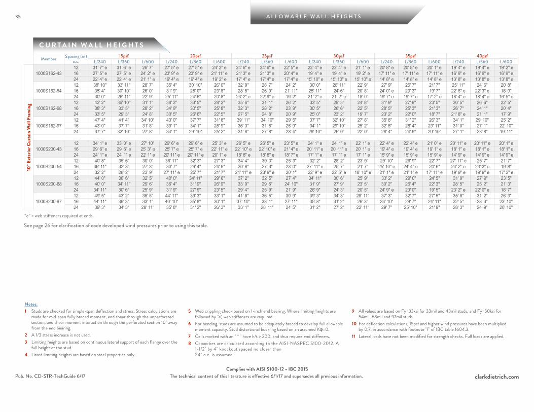
35 A L L O W A B L E W A L L H E I G H T S
clarkdietrich.comThe technical content of this literature is effective 6/1/17 and supersedes all previous information.Pub. No. CD-STR-TechGuide 6/17Complies with AISI S100-12 • IBC 2015
C U R T A I N W A L L H E I G H T S
Notes:1 Studs are checked for simple-span deflection and stress. Stress calculations are
made for mid-span fully braced moment, end shear through the unperforated section, and shear moment interaction through the perforated section 10" away from the end bearing.
2 A 1/3 stress increase is not used.3 Limiting heights are based on continuous lateral support of each flange over the
full height of the stud.4 Listed limiting heights are based on steel properties only.
5 Web crippling check based on 1-inch end bearing. Where limiting heights are followed by "e," web stiffeners are required.
6 For bending, studs are assumed to be adequately braced to develop full allowable moment capacity. Stud distortional buckling based on an assumed Kφ=0.
7 Cells marked with an " * " have h/t > 200, and thus require end stiffeners.8 Capacities are calculated according to the AISI-NASPEC S100-2012. A
1-1/2" by 4" knockout spaced no closer than 24" o.c. is assumed.
9 All values are based on Fy=33ksi for 33mil and 43mil studs, and Fy=50ksi for 54mil, 68mil and 97mil studs.
10 For deflection calculations, 15psf and higher wind pressures have been multiplied by 0.7, in accordance with footnote "f" of IBC table 1604.3.
11 Lateral loads have not been modified for strength checks. Full loads are applied.
Member Spacing (in) o.c.
15psf 20psf 25psf 30psf 35psf 40psfL/240 L/360 L/600 L/240 L/360 L/600 L/240 L/360 L/600 L/240 L/360 L/600 L/240 L/360 L/600 L/240 L/360 L/600
10" E
xter
ior C
urta
in W
all F
ram
ing
1000S162-4312 31' 7" e 31' 6" e 26' 7" 27' 5" e 27' 5" e 24' 2" e 24' 6" e 24' 6" e 22' 5" e 22' 4" e 22' 4" e 21' 1" e 20' 8" e 20' 8" e 20' 1" e 19' 4" e 19' 4" e 19' 2" e16 27' 5" e 27' 5" e 24' 2" e 23' 9" e 23' 9" e 21' 11" e 21' 3" e 21' 3" e 20' 4" e 19' 4" e 19' 4" e 19' 2" e 17' 11" e 17' 11" e 17' 11" e 16' 9" e 16' 9" e 16' 9" e24 22' 4" e 22' 4" e 21' 1" e 19' 4" e 19' 4" e 19' 2" e 17' 4" e 17' 4" e 17' 4" e 15' 10" e 15' 10" e 15' 10" e 14' 8" e 14' 8" e 14' 8" e 13' 8" e 13' 8" e 13' 8" e
1000S162-5412 38' 10" 33' 11" 28' 7" 35' 4" 30' 10" 26' 0" 32' 9" 28' 7" 24' 2" 30' 0" 26' 11" 22' 9" 27' 9" 25' 7" 21' 7" 25' 11" 24' 6" 20' 8" 16 35' 4" 30' 10" 26' 0" 31' 9" 28' 0" 23' 8" 28' 5" 26' 0" 21' 11" 25' 11" 24' 6" 20' 8" 24' 0" e 23' 3" 19' 7" 22' 6" e 22' 3" e 18' 9" 24 30' 0" 26' 11" 22' 9" 25' 11" 24' 6" 20' 8" 23' 2" e 22' 9" e 19' 2" 21' 2" e 21' 2" e 18' 0" 19' 7" e 19' 7" e 17' 2" e 18' 4" e 18' 4" e 16' 5" e
1000S162-6812 42' 2" 36' 10" 31' 1" 38' 3" 33' 5" 28' 2" 35' 6" 31' 1" 26' 2" 33' 5" 29' 3" 24' 8" 31' 9" 27' 9" 23' 5" 30' 5" 26' 6" 22' 5" 16 38' 3" 33' 5" 28' 2" 34' 9" 30' 5" 25' 8" 32' 3" 28' 2" 23' 9" 30' 5" 26' 6" 22' 5" 28' 5" 25' 3" 21' 3" 26' 7" 24' 1" 20' 4" 24 33' 5" 29' 3" 24' 8" 30' 5" 26' 6" 22' 5" 27' 5" 24' 8" 20' 9" 25' 0" 23' 2" 19' 7" 23' 2" 22' 0" 18' 7" 21' 8" e 21' 1" 17' 9"
1000S162-9712 47' 4" 41' 4" 34' 10" 43' 0" 37' 7" 31' 8" 39' 11" 34' 10" 29' 5" 37' 7" 32' 10" 27' 8" 35' 8" 31' 2" 26' 3" 34' 1" 29' 10" 25' 2" 16 43' 0" 37' 7" 31' 8" 39' 1" 34' 1" 28' 9" 36' 3" 31' 8" 26' 9" 34' 1" 29' 10" 25' 2" 32' 5" 28' 4" 23' 11" 31' 0" 27' 1" 22' 10" 24 37' 7" 32' 10" 27' 8" 34' 1" 29' 10" 25' 2" 31' 8" 27' 8" 23' 4" 29' 10" 26' 0" 22' 0" 28' 4" 24' 9" 20' 10" 27' 1" 23' 8" 19' 11"
1000S200-4312 34' 1" e 33' 0" e 27' 10" 29' 6" e 29' 6" e 25' 3" e 26' 5" e 26' 5" e 23' 5" e 24' 1" e 24' 1" e 22' 1" e 22' 4" e 22' 4" e 21' 0" e 20' 11" e 20' 11" e 20' 1" e16 29' 6" e 29' 6" e 25' 3" e 25' 7" e 25' 7" e 22' 11" e 22' 10" e 22' 10" e 21' 4" e 20' 11" e 20' 11" e 20' 1" e 19' 4" e 19' 4" e 19' 1" e 18' 1" e 18' 1" e 18' 1" e24 24' 1" e 24' 1" e 22' 1" e 20' 11" e 20' 11" e 20' 1" e 18' 8" e 18' 8" e 18' 7" e 17' 1" e 17' 1" e 17' 1" e 15' 9" e 15' 9" e 15' 9" e 14' 9" e 14' 9" e 14' 9" e
1000S200-5412 40' 8" 35' 6" 30' 0" 36' 11" 32' 3" 27' 3" 34' 4" 30' 0" 25' 3" 32' 2" 28' 2" 23' 9" 29' 10" 26' 9" 22' 7" 27' 11" e 25' 7" 21' 7" 16 36' 11" 32' 3" 27' 3" 33' 7" 29' 4" 24' 9" 30' 6" 27' 3" 23' 0" 27' 11" e 25' 7" 21' 7" 25' 10" e 24' 4" e 20' 6" 24' 2" e 23' 3" e 19' 8" 24 32' 2" 28' 2" 23' 9" 27' 11" e 25' 7" 21' 7" 24' 11" e 23' 9" e 20' 1" 22' 9" e 22' 5" e 18' 10" e 21' 1" e 21' 1" e 17' 11" e 19' 9" e 19' 9" e 17' 2" e
1000S200-6812 44' 0" 38' 6" 32' 5" 40' 0" 34' 11" 29' 6" 37' 2" 32' 5" 27' 4" 34' 11" 30' 6" 25' 9" 33' 2" 29' 0" 24' 5" 31' 9" 27' 9" 23' 5" 16 40' 0" 34' 11" 29' 6" 36' 4" 31' 9" 26' 9" 33' 9" 29' 6" 24' 10" 31' 9" 27' 9" 23' 5" 30' 2" 26' 4" 22' 3" 28' 5" 25' 2" 21' 3" 24 34' 11" 30' 6" 25' 9" 31' 9" 27' 9" 23' 5" 29' 4" 25' 9" 21' 9" 26' 9" 24' 3" 20' 5" 24' 9" e 23' 0" 19' 5" 23' 2" e 22' 0" e 18' 7"
1000S200-9712 49' 5" 43' 2" 36' 5" 44' 11" 39' 3" 33' 1" 41' 8" 36' 5" 30' 9" 39' 3" 34' 3" 28' 11" 37' 3" 32' 7" 27' 5" 35' 8" 31' 2" 26' 3" 16 44' 11" 39' 3" 33' 1" 40' 10" 35' 8" 30' 1" 37' 10" 33' 1" 27' 11" 35' 8" 31' 2" 26' 3" 33' 10" 29' 7" 24' 11" 32' 5" 28' 3" 23' 10" 24 39' 3" 34' 3" 28' 11" 35' 8" 31' 2" 26' 3" 33' 1" 28' 11" 24' 5" 31' 2" 27' 2" 22' 11" 29' 7" 25' 10" 21' 9" 28' 3" 24' 9" 20' 10"
“e” = web stiffeners required at ends.
See page 26 for clarification of code developed wind pressures prior to using this table.
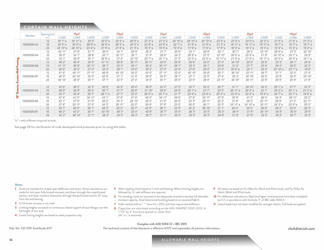
A L L O W A B L E W A L L H E I G H T S
clarkdietrich.comThe technical content of this literature is effective 6/1/17 and supersedes all previous information.
36
Pub. No. CD-STR-TechGuide 6/17Complies with AISI S100-12 • IBC 2015
C U R T A I N W A L L H E I G H T S
36
Notes:1 Studs are checked for simple-span deflection and stress. Stress calculations are
made for mid-span fully braced moment, end shear through the unperforated section, and shear moment interaction through the perforated section 10" away from the end bearing.
2 A 1/3 stress increase is not used.3 Limiting heights are based on continuous lateral support of each flange over the
full height of the stud.4 Listed limiting heights are based on steel properties only.
5 Web crippling check based on 1-inch end bearing. Where limiting heights are followed by "e," web stiffeners are required.
6 For bending, studs are assumed to be adequately braced to develop full allowable moment capacity. Stud distortional buckling based on an assumed Kφ=0.
7 Cells marked with an " * " have h/t > 200, and thus require end stiffeners.8 Capacities are calculated according to the AISI-NASPEC S100-2012. A
1-1/2" by 4" knockout spaced no closer than 24" o.c. is assumed.
9 All values are based on Fy=33ksi for 33mil and 43mil studs, and Fy=50ksi for 54mil, 68mil and 97mil studs.
10 For deflection calculations, 15psf and higher wind pressures have been multiplied by 0.7, in accordance with footnote "f" of IBC table 1604.3.
11 Lateral loads have not been modified for strength checks. Full loads are applied.
Member Spacing (in) o.c.
15psf 20psf 25psf 30psf 35psf 40psfL/240 L/360 L/600 L/240 L/360 L/600 L/240 L/360 L/600 L/240 L/360 L/600 L/240 L/360 L/600 L/240 L/360 L/600
10" E
xter
ior C
urta
in W
all F
ram
ing
1000S250-4312 35' 1" e 34' 11" e 29' 5" 30' 5" e 30' 5" e 26' 9" e 27' 2" e 27' 2" e 24' 10" e 24' 10" e 24' 10" e 23' 4" e 23' 0" e 23' 0" e 22' 2" e 21' 6" e 21' 6" e 21' 3" e16 30' 5" e 30' 5" e 26' 9" e 26' 4" e 26' 4" e 24' 3" e 23' 6" e 23' 6" e 22' 7" e 21' 6" e 21' 6" e 21' 3" e 19' 11" e 19' 11" e 19' 11" e 18' 7" e 18' 7" e 18' 7" e24 24' 10" e 24' 10" e 23' 4" e 21' 6" e 21' 6" e 21' 3" e 19' 3" e 19' 3" e 19' 3" e 17' 6" e 17' 6" e 17' 6" e 16' 3" e 16' 3" e 16' 3" e 15' 2" e 15' 2" e 15' 2" e
1000S250-5412 42' 11" 37' 6" 31' 7" 39' 0" 34' 1" 28' 9" 36' 2" 31' 7" 26' 8" 33' 1" 29' 9" 25' 1" 30' 7" 28' 3" 23' 10" 28' 8" e 27' 0" 22' 10" 16 39' 0" 34' 1" 28' 9" 35' 1" 30' 11" 26' 1" 31' 4" 28' 9" 24' 3" 28' 8" e 27' 0" 22' 10" 26' 6" e 25' 8" e 21' 8" 24' 10" e 24' 7" e 20' 9" 24 33' 1" 29' 9" 25' 1" 28' 8" e 27' 0" 22' 10" 25' 7" e 25' 1" e 21' 2" 23' 5" e 23' 5" e 19' 11" e 21' 8" e 21' 8" e 18' 11" e 20' 3" e 20' 3" e 18' 1" e
1000S250-6812 46' 2" 40' 4" 34' 0" 41' 11" 36' 8" 30' 11" 38' 11" 34' 0" 28' 8" 36' 8" 32' 0" 27' 0" 34' 10" 30' 5" 25' 8" 33' 3" 29' 1" 24' 6" 16 41' 11" 36' 8" 30' 11" 38' 1" 33' 3" 28' 1" 35' 4" 30' 11" 26' 1" 33' 3" 29' 1" 24' 6" 31' 2" 27' 7" 23' 4" 29' 2" 26' 5" 22' 3" 24 36' 8" 32' 0" 27' 0" 33' 3" 29' 1" 24' 6" 30' 2" 27' 0" 22' 9" 27' 6" 25' 5" 21' 5" 25' 6" e 24' 1" 20' 4" 23' 10" e 23' 1" e 19' 6"
1000S250-9712 51' 6" 44' 11" 37' 11" 46' 9" 40' 10" 34' 5" 43' 5" 37' 11" 32' 0" 40' 10" 35' 8" 30' 1" 38' 10" 33' 11" 28' 7" 37' 1" 32' 5" 27' 4" 16 46' 9" 40' 10" 34' 5" 42' 6" 37' 1" 31' 4" 39' 5" 34' 5" 29' 1" 37' 1" 32' 5" 27' 4" 35' 3" 30' 10" 26' 0" 33' 9" 29' 5" 24' 10" 24 40' 10" 35' 8" 30' 1" 37' 1" 32' 5" 27' 4" 34' 5" 30' 1" 25' 5" 32' 5" 28' 4" 23' 11" 30' 10" 26' 11" 22' 8" 29' 5" 25' 9" 21' 8"
1000S300-5412 43' 9" 38' 3" 32' 3" 39' 9" 34' 9" 29' 4" 36' 9" 32' 3" 27' 2" 33' 7" 30' 4" 25' 7" 31' 1" 28' 10" 24' 4" 29' 1" e 27' 7" 23' 3" 16 39' 9" 34' 9" 29' 4" 35' 7" 31' 7" 26' 8" 31' 10" 29' 4" 24' 9" 29' 1" e 27' 7" 23' 3" 26' 11" e 26' 2" e 22' 1" 25' 2" e 25' 1" e 21' 2" e24 33' 7" 30' 4" 25' 7" 29' 1" e 27' 7" 23' 3" 26' 0" e 25' 7" e 21' 7" 23' 9" e 23' 9" e 20' 4" e 22' 0" e 22' 0" e 19' 4" e 20' 7" e 20' 7" e 18' 6" e
1000S300-6812 47' 5" 41' 5" 34' 11" 43' 1" 37' 8" 31' 9" 40' 0" 34' 11" 29' 6" 37' 8" 32' 11" 27' 9" 35' 9" 31' 3" 26' 4" 34' 3" 29' 11" 25' 2" 16 43' 1" 37' 8" 31' 9" 39' 2" 34' 3" 28' 10" 36' 4" 31' 9" 26' 9" 34' 3" 29' 11" 25' 2" 31' 9" 28' 5" 23' 11" 29' 8" 27' 2" 22' 11" 24 37' 8" 32' 11" 27' 9" 34' 3" 29' 11" 25' 2" 30' 8" 27' 9" 23' 5" 28' 0" 26' 1" 22' 0" 25' 11" e 24' 10" e 20' 11" 24' 3" e 23' 9" e 20' 0"
1000S300-9712 53' 1" 46' 5" 39' 1" 48' 3" 42' 2" 35' 7" 44' 9" 39' 1" 33' 0" 42' 2" 36' 10" 31' 1" 40' 0" 35' 0" 29' 6" 38' 3" 33' 5" 28' 3" 16 48' 3" 42' 2" 35' 7" 43' 10" 38' 3" 32' 4" 40' 8" 35' 7" 30' 0" 38' 3" 33' 5" 28' 3" 36' 4" 31' 9" 26' 10" 34' 9" 30' 5" 25' 8" 24 42' 2" 36' 10" 31' 1" 38' 3" 33' 5" 28' 3" 35' 7" 31' 1" 26' 2" 33' 5" 29' 3" 24' 8" 31' 9" 27' 9" 23' 5" 30' 5" 26' 7" 22' 5"
“e” = web stiffeners required at ends.
See page 26 for clarification of code developed wind pressures prior to using this table.
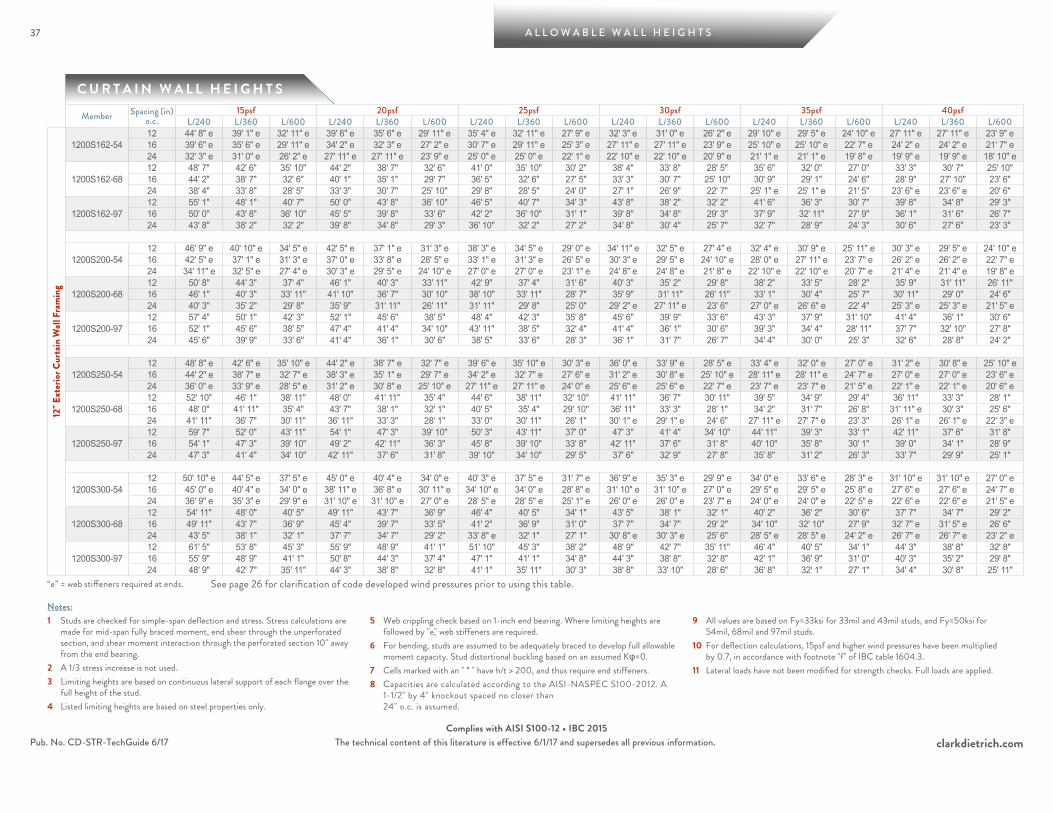
37 A L L O W A B L E W A L L H E I G H T S
clarkdietrich.comThe technical content of this literature is effective 6/1/17 and supersedes all previous information.Pub. No. CD-STR-TechGuide 6/17Complies with AISI S100-12 • IBC 2015
C U R T A I N W A L L H E I G H T S
Notes:1 Studs are checked for simple-span deflection and stress. Stress calculations are
made for mid-span fully braced moment, end shear through the unperforated section, and shear moment interaction through the perforated section 10" away from the end bearing.
2 A 1/3 stress increase is not used.3 Limiting heights are based on continuous lateral support of each flange over the
full height of the stud.4 Listed limiting heights are based on steel properties only.
5 Web crippling check based on 1-inch end bearing. Where limiting heights are followed by "e," web stiffeners are required.
6 For bending, studs are assumed to be adequately braced to develop full allowable moment capacity. Stud distortional buckling based on an assumed Kφ=0.
7 Cells marked with an " * " have h/t > 200, and thus require end stiffeners.8 Capacities are calculated according to the AISI-NASPEC S100-2012. A
1-1/2" by 4" knockout spaced no closer than 24" o.c. is assumed.
9 All values are based on Fy=33ksi for 33mil and 43mil studs, and Fy=50ksi for 54mil, 68mil and 97mil studs.
10 For deflection calculations, 15psf and higher wind pressures have been multiplied by 0.7, in accordance with footnote "f" of IBC table 1604.3.
11 Lateral loads have not been modified for strength checks. Full loads are applied.
Member Spacing (in) o.c.
15psf 20psf 25psf 30psf 35psf 40psfL/240 L/360 L/600 L/240 L/360 L/600 L/240 L/360 L/600 L/240 L/360 L/600 L/240 L/360 L/600 L/240 L/360 L/600
12" E
xter
ior C
urta
in W
all F
ram
ing
1200S162-5412 44' 8" e 39' 1" e 32' 11" e 39' 6" e 35' 6" e 29' 11" e 35' 4" e 32' 11" e 27' 9" e 32' 3" e 31' 0" e 26' 2" e 29' 10" e 29' 5" e 24' 10" e 27' 11" e 27' 11" e 23' 9" e 16 39' 6" e 35' 6" e 29' 11" e 34' 2" e 32' 3" e 27' 2" e 30' 7" e 29' 11" e 25' 3" e 27' 11" e 27' 11" e 23' 9" e 25' 10" e 25' 10" e 22' 7" e 24' 2" e 24' 2" e 21' 7" e24 32' 3" e 31' 0" e 26' 2" e 27' 11" e 27' 11" e 23' 9" e 25' 0" e 25' 0" e 22' 1" e 22' 10" e 22' 10" e 20' 9" e 21' 1" e 21' 1" e 19' 8" e 19' 9" e 19' 9" e 18' 10" e
1200S162-6812 48' 7" 42' 6" 35' 10" 44' 2" 38' 7" 32' 6" 41' 0" 35' 10" 30' 2" 38' 4" 33' 8" 28' 5" 35' 6" 32' 0" 27' 0" 33' 3" 30' 7" 25' 10" 16 44' 2" 38' 7" 32' 6" 40' 1" 35' 1" 29' 7" 36' 5" 32' 6" 27' 5" 33' 3" 30' 7" 25' 10" 30' 9" 29' 1" 24' 6" 28' 9" 27' 10" 23' 6" 24 38' 4" 33' 8" 28' 5" 33' 3" 30' 7" 25' 10" 29' 8" 28' 5" 24' 0" 27' 1" 26' 9" 22' 7" 25' 1" e 25' 1" e 21' 5" 23' 6" e 23' 6" e 20' 6"
1200S162-9712 55' 1" 48' 1" 40' 7" 50' 0" 43' 8" 36' 10" 46' 5" 40' 7" 34' 3" 43' 8" 38' 2" 32' 2" 41' 6" 36' 3" 30' 7" 39' 8" 34' 8" 29' 3" 16 50' 0" 43' 8" 36' 10" 45' 5" 39' 8" 33' 6" 42' 2" 36' 10" 31' 1" 39' 8" 34' 8" 29' 3" 37' 9" 32' 11" 27' 9" 36' 1" 31' 6" 26' 7" 24 43' 8" 38' 2" 32' 2" 39' 8" 34' 8" 29' 3" 36' 10" 32' 2" 27' 2" 34' 8" 30' 4" 25' 7" 32' 7" 28' 9" 24' 3" 30' 6" 27' 6" 23' 3"
1200S200-5412 46' 9" e 40' 10" e 34' 5" e 42' 5" e 37' 1" e 31' 3" e 38' 3" e 34' 5" e 29' 0" e 34' 11" e 32' 5" e 27' 4" e 32' 4" e 30' 9" e 25' 11" e 30' 3" e 29' 5" e 24' 10" e 16 42' 5" e 37' 1" e 31' 3" e 37' 0" e 33' 8" e 28' 5" e 33' 1" e 31' 3" e 26' 5" e 30' 3" e 29' 5" e 24' 10" e 28' 0" e 27' 11" e 23' 7" e 26' 2" e 26' 2" e 22' 7" e24 34' 11" e 32' 5" e 27' 4" e 30' 3" e 29' 5" e 24' 10" e 27' 0" e 27' 0" e 23' 1" e 24' 8" e 24' 8" e 21' 8" e 22' 10" e 22' 10" e 20' 7" e 21' 4" e 21' 4" e 19' 8" e
1200S200-6812 50' 8" 44' 3" 37' 4" 46' 1" 40' 3" 33' 11" 42' 9" 37' 4" 31' 6" 40' 3" 35' 2" 29' 8" 38' 2" 33' 5" 28' 2" 35' 9" 31' 11" 26' 11" 16 46' 1" 40' 3" 33' 11" 41' 10" 36' 7" 30' 10" 38' 10" 33' 11" 28' 7" 35' 9" 31' 11" 26' 11" 33' 1" 30' 4" 25' 7" 30' 11" 29' 0" 24' 6" 24 40' 3" 35' 2" 29' 8" 35' 9" 31' 11" 26' 11" 31' 11" 29' 8" 25' 0" 29' 2" e 27' 11" e 23' 6" 27' 0" e 26' 6" e 22' 4" 25' 3" e 25' 3" e 21' 5" e
1200S200-9712 57' 4" 50' 1" 42' 3" 52' 1" 45' 6" 38' 5" 48' 4" 42' 3" 35' 8" 45' 6" 39' 9" 33' 6" 43' 3" 37' 9" 31' 10" 41' 4" 36' 1" 30' 6" 16 52' 1" 45' 6" 38' 5" 47' 4" 41' 4" 34' 10" 43' 11" 38' 5" 32' 4" 41' 4" 36' 1" 30' 6" 39' 3" 34' 4" 28' 11" 37' 7" 32' 10" 27' 8" 24 45' 6" 39' 9" 33' 6" 41' 4" 36' 1" 30' 6" 38' 5" 33' 6" 28' 3" 36' 1" 31' 7" 26' 7" 34' 4" 30' 0" 25' 3" 32' 6" 28' 8" 24' 2"
1200S250-5412 48' 8" e 42' 6" e 35' 10" e 44' 2" e 38' 7" e 32' 7" e 39' 6" e 35' 10" e 30' 3" e 36' 0" e 33' 9" e 28' 5" e 33' 4" e 32' 0" e 27' 0" e 31' 2" e 30' 8" e 25' 10" e 16 44' 2" e 38' 7" e 32' 7" e 38' 3" e 35' 1" e 29' 7" e 34' 2" e 32' 7" e 27' 6" e 31' 2" e 30' 8" e 25' 10" e 28' 11" e 28' 11" e 24' 7" e 27' 0" e 27' 0" e 23' 6" e24 36' 0" e 33' 9" e 28' 5" e 31' 2" e 30' 8" e 25' 10" e 27' 11" e 27' 11" e 24' 0" e 25' 6" e 25' 6" e 22' 7" e 23' 7" e 23' 7" e 21' 5" e 22' 1" e 22' 1" e 20' 6" e
1200S250-6812 52' 10" 46' 1" 38' 11" 48' 0" 41' 11" 35' 4" 44' 6" 38' 11" 32' 10" 41' 11" 36' 7" 30' 11" 39' 5" 34' 9" 29' 4" 36' 11" 33' 3" 28' 1" 16 48' 0" 41' 11" 35' 4" 43' 7" 38' 1" 32' 1" 40' 5" 35' 4" 29' 10" 36' 11" 33' 3" 28' 1" 34' 2" 31' 7" 26' 8" 31' 11" e 30' 3" 25' 6" 24 41' 11" 36' 7" 30' 11" 36' 11" 33' 3" 28' 1" 33' 0" 30' 11" 26' 1" 30' 1" e 29' 1" e 24' 6" 27' 11" e 27' 7" e 23' 3" 26' 1" e 26' 1" e 22' 3" e
1200S250-9712 59' 7" 52' 0" 43' 11" 54' 1" 47' 3" 39' 10" 50' 3" 43' 11" 37' 0" 47' 3" 41' 4" 34' 10" 44' 11" 39' 3" 33' 1" 42' 11" 37' 6" 31' 8" 16 54' 1" 47' 3" 39' 10" 49' 2" 42' 11" 36' 3" 45' 8" 39' 10" 33' 8" 42' 11" 37' 6" 31' 8" 40' 10" 35' 8" 30' 1" 39' 0" 34' 1" 28' 9" 24 47' 3" 41' 4" 34' 10" 42' 11" 37' 6" 31' 8" 39' 10" 34' 10" 29' 5" 37' 6" 32' 9" 27' 8" 35' 8" 31' 2" 26' 3" 33' 7" 29' 9" 25' 1"
1200S300-5412 50' 10" e 44' 5" e 37' 5" e 45' 0" e 40' 4" e 34' 0" e 40' 3" e 37' 5" e 31' 7" e 36' 9" e 35' 3" e 29' 9" e 34' 0" e 33' 6" e 28' 3" e 31' 10" e 31' 10" e 27' 0" e16 45' 0" e 40' 4" e 34' 0" e 38' 11" e 36' 8" e 30' 11" e 34' 10" e 34' 0" e 28' 8" e 31' 10" e 31' 10" e 27' 0" e 29' 5" e 29' 5" e 25' 8" e 27' 6" e 27' 6" e 24' 7" e24 36' 9" e 35' 3" e 29' 9" e 31' 10" e 31' 10" e 27' 0" e 28' 5" e 28' 5" e 25' 1" e 26' 0" e 26' 0" e 23' 7" e 24' 0" e 24' 0" e 22' 5" e 22' 6" e 22' 6" e 21' 5" e
1200S300-6812 54' 11" 48' 0" 40' 5" 49' 11" 43' 7" 36' 9" 46' 4" 40' 5" 34' 1" 43' 5" 38' 1" 32' 1" 40' 2" 36' 2" 30' 6" 37' 7" 34' 7" 29' 2" 16 49' 11" 43' 7" 36' 9" 45' 4" 39' 7" 33' 5" 41' 2" 36' 9" 31' 0" 37' 7" 34' 7" 29' 2" 34' 10" 32' 10" 27' 9" 32' 7" e 31' 5" e 26' 6" 24 43' 5" 38' 1" 32' 1" 37' 7" 34' 7" 29' 2" 33' 8" e 32' 1" 27' 1" 30' 8" e 30' 3" e 25' 6" 28' 5" e 28' 5" e 24' 2" e 26' 7" e 26' 7" e 23' 2" e
1200S300-9712 61' 5" 53' 8" 45' 3" 55' 9" 48' 9" 41' 1" 51' 10" 45' 3" 38' 2" 48' 9" 42' 7" 35' 11" 46' 4" 40' 5" 34' 1" 44' 3" 38' 8" 32' 8" 16 55' 9" 48' 9" 41' 1" 50' 8" 44' 3" 37' 4" 47' 1" 41' 1" 34' 8" 44' 3" 38' 8" 32' 8" 42' 1" 36' 9" 31' 0" 40' 3" 35' 2" 29' 8" 24 48' 9" 42' 7" 35' 11" 44' 3" 38' 8" 32' 8" 41' 1" 35' 11" 30' 3" 38' 8" 33' 10" 28' 6" 36' 8" 32' 1" 27' 1" 34' 4" 30' 8" 25' 11"
“e” = web stiffeners required at ends. See page 26 for clarification of code developed wind pressures prior to using this table.

A L L O W A B L E W A L L H E I G H T S
clarkdietrich.comThe technical content of this literature is effective 6/1/17 and supersedes all previous information.
38
Pub. No. CD-STR-TechGuide 6/17Complies with AISI S100-12 • IBC 2015
C U R T A I N W A L L H E I G H T S
38
Notes:1 Studs are checked for simple-span deflection and stress. Stress calculations are
made for mid-span fully braced moment, end shear through the unperforated section, and shear moment interaction through the perforated section 10" away from the end bearing.
2 A 1/3 stress increase is not used.3 Limiting heights are based on continuous lateral support of each flange over the
full height of the stud.4 Listed limiting heights are based on steel properties only.
5 Web crippling check based on 1-inch end bearing. Where limiting heights are followed by "e," web stiffeners are required.
6 For bending, studs are assumed to be adequately braced to develop full allowable moment capacity. Stud distortional buckling based on an assumed Kφ=0.
7 Cells marked with an " * " have h/t > 200, and thus require end stiffeners.8 Capacities are calculated according to the AISI-NASPEC S100-2012. A
1-1/2" by 4" knockout spaced no closer than 24" o.c. is assumed.
9 All values are based on Fy=33ksi for 33mil and 43mil studs, and Fy=50ksi for 54mil, 68mil and 97mil studs.
10 For deflection calculations, 15psf and higher wind pressures have been multiplied by 0.7, in accordance with footnote "f" of IBC table 1604.3.
11 Lateral loads have not been modified for strength checks. Full loads are applied.
Member Spacing (in) o.c.
15psf 20psf 25psf 30psf 35psf 40psfL/240 L/360 L/600 L/240 L/360 L/600 L/240 L/360 L/600 L/240 L/360 L/600 L/240 L/360 L/600 L/240 L/360 L/600
14" E
xter
ior C
urta
in W
all F
ram
ing
1400S162-5412 48' 2" e 43' 11" e 37' 1" e 41' 8" e 39' 11" e 33' 8" e 37' 4" e 37' 1" e 31' 3" e 34' 1" e 34' 1" e 29' 5" e 31' 6" e 31' 6" e 27' 11" e 29' 6" e 29' 6" e 26' 9" e16 41' 8" e 39' 11" e 33' 8" e 36' 1" e 36' 1" e 30' 7" e 32' 4" e 32' 4" e 28' 5" e 29' 6" e 29' 6" e 26' 9" e 27' 4" e 27' 4" e 25' 5" e 25' 6" e 25' 6" e 24' 3" e24 34' 1" e 34' 1" e 29' 5" e 29' 6" e 29' 6" e 26' 9" e 26' 4" e 26' 4" e 24' 10" e 24' 1" e 24' 1" e 23' 4" e 22' 3" e 22' 3" e 22' 2" e 20' 10" e 20' 10" e 20' 10" e
1400S162-6812 54' 10" 47' 11" 40' 5" 49' 10" 43' 6" 36' 8" 44' 7" 40' 5" 34' 1" 40' 9" 38' 0" 32' 1" 37' 8" 36' 1" 30' 5" 35' 3" 34' 6" 29' 1" 16 49' 10" 43' 6" 36' 8" 43' 2" 39' 6" 33' 4" 38' 8" 36' 8" 30' 11" 35' 3" 34' 6" 29' 1" 32' 8" 32' 8" 27' 8" 30' 6" e 30' 6" e 26' 6" 24 40' 9" 38' 0" 32' 1" 35' 3" 34' 6" 29' 1" 31' 6" 31' 6" 27' 0" 28' 10" e 28' 10" e 25' 5" 26' 8" e 26' 8" e 24' 2" e 24' 11" e 24' 11" e 23' 1" e
1400S162-9712 62' 5" 54' 6" 46' 0" 56' 8" 49' 6" 41' 9" 52' 7" 46' 0" 38' 9" 49' 6" 43' 3" 36' 6" 47' 0" 41' 1" 34' 8" 45' 0" 39' 4" 33' 2" 16 56' 8" 49' 6" 41' 9" 51' 6" 45' 0" 37' 11" 47' 10" 41' 9" 35' 3" 45' 0" 39' 4" 33' 2" 42' 9" 37' 4" 31' 6" 40' 0" 35' 9" 30' 1" 24 49' 6" 43' 3" 36' 6" 45' 0" 39' 4" 33' 2" 41' 4" 36' 6" 30' 9" 37' 9" 34' 4" 29' 0" 34' 11" 32' 7" 27' 6" 32' 8" 31' 2" 26' 4"
1400S200-5412 52' 4" e 45' 11" e 38' 8" e 45' 4" e 41' 8" e 35' 2" e 40' 7" e 38' 8" e 32' 8" e 37' 0" e 36' 5" e 30' 9" e 34' 3" e 34' 3" e 29' 2" e 32' 1" e 32' 1" e 27' 11" e16 45' 4" e 41' 8" e 35' 2" e 39' 3" e 37' 10" e 31' 11" e 35' 2" e 35' 2" e 29' 8" e 32' 1" e 32' 1" e 27' 11" e 29' 8" e 29' 8" e 26' 6" e 27' 9" e 27' 9" e 25' 4" e24 37' 0" e 36' 5" e 30' 9" e 32' 1" e 32' 1" e 27' 11" e 28' 8" e 28' 8" e 25' 11" e 26' 2" e 26' 2" e 24' 5" e 24' 3" e 24' 3" e 23' 2" e 22' 8" e 22' 8" e 22' 2" e
1400S200-6812 57' 1" 49' 10" 42' 1" 51' 10" 45' 4" 38' 3" 48' 2" 42' 1" 35' 6" 44' 0" 39' 7" 33' 5" 40' 9" 37' 7" 31' 9" 38' 1" 36' 0" 30' 4" 16 51' 10" 45' 4" 38' 3" 46' 8" 41' 2" 34' 9" 41' 9" 38' 3" 32' 3" 38' 1" 36' 0" 30' 4" 35' 3" e 34' 2" 28' 10" 33' 0" e 32' 8" e 27' 7" 24 44' 0" 39' 7" 33' 5" 38' 1" 36' 0" 30' 4" 34' 1" e 33' 5" e 28' 2" 31' 1" e 31' 1" e 26' 6" 28' 10" e 28' 10" e 25' 2" e 26' 11" e 26' 11" e 24' 1" e
1400S200-9712 64' 10" 56' 7" 47' 9" 58' 11" 51' 5" 43' 5" 54' 8" 47' 9" 40' 3" 51' 5" 44' 11" 37' 11" 48' 10" 42' 8" 36' 0" 46' 9" 40' 10" 34' 5" 16 58' 11" 51' 5" 43' 5" 53' 6" 46' 9" 39' 5" 49' 8" 43' 5" 36' 7" 46' 9" 40' 10" 34' 5" 44' 5" 38' 9" 32' 9" 42' 6" 37' 1" 31' 3" 24 51' 5" 44' 11" 37' 11" 46' 9" 40' 10" 34' 5" 43' 5" 37' 11" 32' 0" 40' 5" 35' 8" 30' 1" 37' 5" 33' 11" 28' 7" 35' 0" 32' 5" 27' 4"
1400S250-5412 54' 5" e 47' 9" e 40' 3" e 47' 1" e 43' 5" e 36' 7" e 42' 2" e 40' 3" e 34' 0" e 38' 6" e 37' 11" e 32' 0" e 35' 7" e 35' 7" e 30' 4" e 33' 4" e 33' 4" e 29' 0" e16 47' 1" e 43' 5" e 36' 7" e 40' 10" e 39' 5" e 33' 3" e 36' 6" e 36' 6" e 30' 10" e 33' 4" e 33' 4" e 29' 0" e 30' 10" e 30' 10" e 27' 7" e 28' 10" e 28' 10" e 26' 5" e24 38' 6" e 37' 11" e 32' 0" e 33' 4" e 33' 4" e 29' 0" e 29' 10" e 29' 10" e 26' 11" e 27' 2" e 27' 2" e 25' 4" e 25' 2" e 25' 2" e 24' 1" e 23' 7" e 23' 7" e 23' 1" e
1400S250-6812 59' 5" 51' 11" 43' 9" 54' 0" 47' 2" 39' 9" 50' 0" 43' 9" 36' 11" 45' 8" 41' 2" 34' 9" 42' 3" 39' 1" 33' 0" 39' 7" 37' 5" 31' 7" 16 54' 0" 47' 2" 39' 9" 48' 5" 42' 10" 36' 2" 43' 4" 39' 9" 33' 6" 39' 7" 37' 5" 31' 7" 36' 7" e 35' 7" e 30' 0" 34' 3" e 34' 0" e 28' 8" 24 45' 8" 41' 2" 34' 9" 39' 7" 37' 5" 31' 7" 35' 4" e 34' 9" e 29' 4" 32' 3" e 32' 3" e 27' 7" e 29' 11" e 29' 11" e 26' 2" e 28' 0" e 28' 0" e 25' 1" e
1400S250-9712 67' 3" 58' 9" 49' 6" 61' 1" 53' 4" 45' 0" 56' 8" 49' 6" 41' 9" 53' 4" 46' 7" 39' 4" 50' 8" 44' 3" 37' 4" 48' 6" 42' 4" 35' 9" 16 61' 1" 53' 4" 45' 0" 55' 6" 48' 6" 40' 11" 51' 6" 45' 0" 37' 11" 48' 6" 42' 4" 35' 9" 46' 1" 40' 3" 33' 11" 44' 1" 38' 6" 32' 5" 24 53' 4" 46' 7" 39' 4" 48' 6" 42' 4" 35' 9" 45' 0" 39' 4" 33' 2" 41' 11" 37' 0" 31' 2" 38' 10" 35' 2" 29' 8" 36' 3" 33' 7" 28' 4"
1400S300-5412 55' 5" e 48' 5" e 40' 10" e 48' 3" e 44' 0" e 37' 1" e 43' 2" e 40' 10" e 34' 5" e 39' 5" e 38' 5" e 32' 5" e 36' 6" e 36' 6" e 30' 9" e 34' 1" e 34' 1" e 29' 5" e16 48' 3" e 44' 0" e 37' 1" e 41' 9" e 39' 11" e 33' 8" e 37' 5" e 37' 1" e 31' 3" e 34' 1" e 34' 1" e 29' 5" e 31' 7" e 31' 7" e 28' 0" e 29' 7" e 29' 7" e 26' 9" e24 39' 5" e 38' 5" e 32' 5" e 34' 1" e 34' 1" e 29' 5" e 30' 6" e 30' 6" e 27' 4" e 27' 10" e 27' 10" e 25' 9" e 25' 10" e 25' 10" e 24' 5" e 24' 2" e 24' 2" e 23' 4" e
1400S300-6812 61' 0" 53' 3" 44' 11" 55' 5" 48' 5" 40' 10" 51' 2" 44' 11" 37' 11" 46' 9" 42' 3" 35' 8" 43' 3" 40' 2" 33' 10" 40' 6" e 38' 5" 32' 5" 16 55' 5" 48' 5" 40' 10" 49' 7" 44' 0" 37' 1" 44' 4" 40' 10" 34' 5" 40' 6" e 38' 5" 32' 5" 37' 6" e 36' 6" e 30' 9" 35' 1" e 34' 11" e 29' 5" 24 46' 9" 42' 3" 35' 8" 40' 6" e 38' 5" 32' 5" 36' 2" e 35' 8" e 30' 1" 33' 1" e 33' 1" e 28' 4" e 30' 7" e 30' 7" e 26' 11" e 28' 7" e 28' 7" e 25' 9" e
1400S300-9712 69' 3" 60' 6" 51' 0" 62' 11" 55' 0" 46' 4" 58' 5" 51' 0" 43' 1" 55' 0" 48' 0" 40' 6" 52' 3" 45' 7" 38' 6" 49' 11" 43' 8" 36' 10" 16 62' 11" 55' 0" 46' 4" 57' 2" 49' 11" 42' 2" 53' 1" 46' 4" 39' 1" 49' 11" 43' 8" 36' 10" 47' 5" 41' 5" 35' 0" 45' 5" 39' 8" 33' 5" 24 55' 0" 48' 0" 40' 6" 49' 11" 43' 8" 36' 10" 46' 4" 40' 6" 34' 2" 42' 11" 38' 1" 32' 2" 39' 8" 36' 3" 30' 6" 37' 2" 34' 8" 29' 3"
“e” = web stiffeners required at ends. See page 26 for clarification of code developed wind pressures prior to using this table.
A L L O W A B L E A X I A L & L A T E R A L L O A D T A B L E S
39
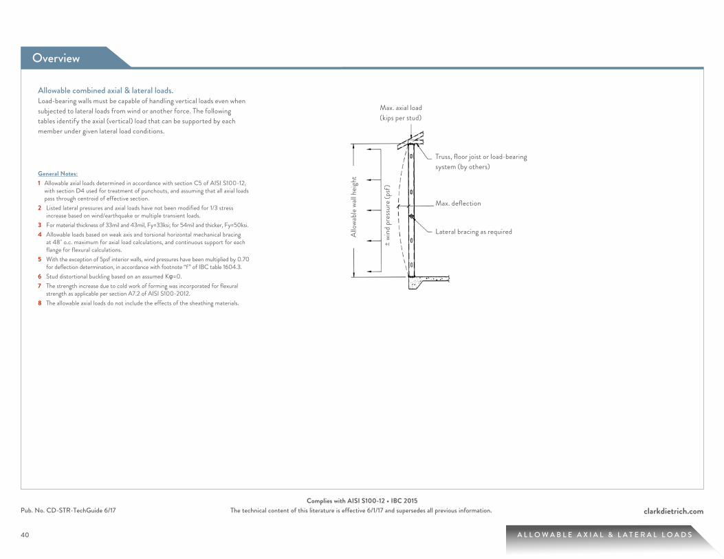
Overview
40
clarkdietrich.comPub. No. CD-STR-TechGuide 6/17 The technical content of this literature is effective 6/1/17 and supersedes all previous information.Complies with AISI S100-12 • IBC 2015
40 A L L O W A B L E A X I A L & L A T E R A L L O A D S
Allowable combined axial & lateral loads.Load-bearing walls must be capable of handling vertical loads even when subjected to lateral loads from wind or another force. The following tables identify the axial (vertical) load that can be supported by each member under given lateral load conditions.
General Notes:1 Allowable axial loads determined in accordance with section C5 of AISI S100-12,
with section D4 used for treatment of punchouts, and assuming that all axial loads pass through centroid of effective section.
2 Listed lateral pressures and axial loads have not been modified for 1/3 stress increase based on wind/earthquake or multiple transient loads.
3 For material thickness of 33mil and 43mil, Fy=33ksi; for 54mil and thicker, Fy=50ksi.4 Allowable loads based on weak axis and torsional horizontal mechanical bracing
at 48" o.c. maximum for axial load calculations, and continuous support for each flange for flexural calculations.
5 With the exception of 5psf interior walls, wind pressures have been multiplied by 0.70 for deflection determination, in accordance with footnote “f” of IBC table 1604.3.
6 Stud distortional buckling based on an assumed Kφ=0.7 The strength increase due to cold work of forming was incorporated for flexural
strength as applicable per section A7.2 of AISI S100-2012.8 The allowable axial loads do not include the effects of the sheathing materials.
Truss, floor joist or load-bearing system (by others)
Max. deflection
Lateral bracing as required
Max. axial load (kips per stud)
± wi
nd p
ress
ure (
psf)
Allo
wabl
e wall
heig
ht
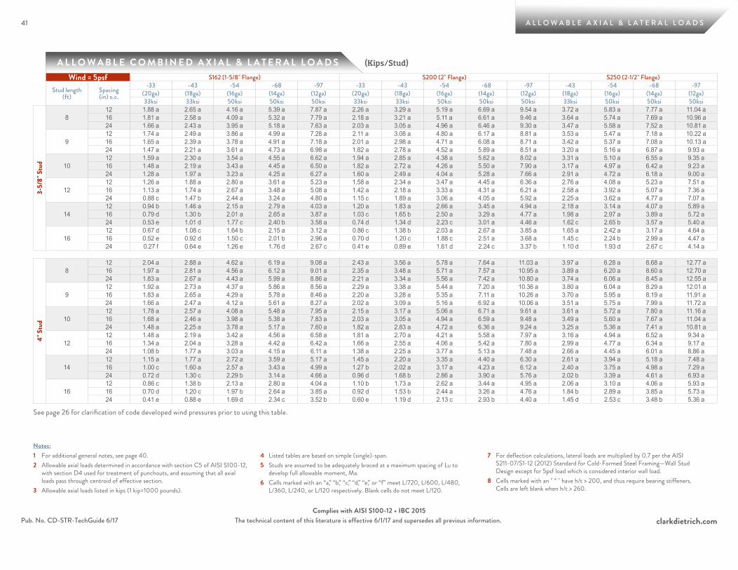
41
clarkdietrich.comPub. No. CD-STR-TechGuide 6/17 The technical content of this literature is effective 6/1/17 and supersedes all previous information.Complies with AISI S100-12 • IBC 2015
41
A L L O W A B L E C O M B I N E D A X I A L & L A T E R A L L O A D S
A L L O W A B L E A X I A L & L A T E R A L L O A D S
(Kips/Stud)
Notes:1 For additional general notes, see page 40.2 Allowable axial loads determined in accordance with section C5 of AISI S100-12,
with section D4 used for treatment of punchouts, and assuming that all axial loads pass through centroid of effective section.
3 Allowable axial loads listed in kips (1 kip=1000 pounds).
4 Listed tables are based on simple (single)-span.5 Studs are assumed to be adequately braced at a maximum spacing of Lu to
develop full allowable moment, Ma.6 Cells marked with an “a,” “b,” “c,” “d,” “e,” or “f” meet L/720, L/600, L/480,
L/360, L/240, or L/120 respectively. Blank cells do not meet L/120.
7 For deflection calculations, lateral loads are multiplied by 0.7 per the AISI S211-07/S1-12 (2012) Standard for Cold-Formed Steel Framing—Wall Stud Design except for 5psf load which is considered interior wall load.
8 Cells marked with an " * " have h/t > 200, and thus require bearing stiffeners. Cells are left blank when h/t > 260.
See page 26 for clarification of code developed wind pressures prior to using this table.
Wind = 5psf S162 (1-5/8" Flange) S200 (2" Flange) S250 (2-1/2" Flange)
Stud length (ft)
Spacing (in) o.c.
-33 -43 -54 -68 -97 -33 -43 -54 -68 -97 -43 -54 -68 -97(20ga) (18ga) (16ga) (14ga) (12ga) (20ga) (18ga) (16ga) (14ga) (12ga) (18ga) (16ga) (14ga) (12ga)33ksi 33ksi 50ksi 50ksi 50ksi 33ksi 33ksi 50ksi 50ksi 50ksi 33ksi 50ksi 50ksi 50ksi
3-5/
8" S
tud
812 1.88 a 2.65 a 4.16 a 5.39 a 7.87 a 2.26 a 3.29 a 5.19 a 6.69 a 9.54 a 3.72 a 5.83 a 7.77 a 11.04 a 16 1.81 a 2.58 a 4.09 a 5.32 a 7.79 a 2.18 a 3.21 a 5.11 a 6.61 a 9.46 a 3.64 a 5.74 a 7.69 a 10.96 a 24 1.66 a 2.43 a 3.95 a 5.18 a 7.63 a 2.03 a 3.05 a 4.96 a 6.46 a 9.30 a 3.47 a 5.58 a 7.52 a 10.81 a
912 1.74 a 2.49 a 3.86 a 4.99 a 7.28 a 2.11 a 3.08 a 4.80 a 6.17 a 8.81 a 3.53 a 5.47 a 7.18 a 10.22 a 16 1.65 a 2.39 a 3.78 a 4.91 a 7.18 a 2.01 a 2.98 a 4.71 a 6.08 a 8.71 a 3.42 a 5.37 a 7.08 a 10.13 a 24 1.47 a 2.21 a 3.61 a 4.73 a 6.98 a 1.82 a 2.78 a 4.52 a 5.89 a 8.51 a 3.20 a 5.16 a 6.87 a 9.93 a
1012 1.59 a 2.30 a 3.54 a 4.55 a 6.62 a 1.94 a 2.85 a 4.38 a 5.62 a 8.02 a 3.31 a 5.10 a 6.55 a 9.35 a 16 1.48 a 2.19 a 3.43 a 4.45 a 6.50 a 1.82 a 2.72 a 4.26 a 5.50 a 7.90 a 3.17 a 4.97 a 6.42 a 9.23 a 24 1.28 a 1.97 a 3.23 a 4.25 a 6.27 a 1.60 a 2.49 a 4.04 a 5.28 a 7.66 a 2.91 a 4.72 a 6.18 a 9.00 a
1212 1.26 a 1.88 a 2.80 a 3.61 a 5.23 a 1.58 a 2.34 a 3.47 a 4.45 a 6.36 a 2.76 a 4.08 a 5.23 a 7.51 a 16 1.13 a 1.74 a 2.67 a 3.48 a 5.08 a 1.42 a 2.18 a 3.33 a 4.31 a 6.21 a 2.58 a 3.92 a 5.07 a 7.36 a 24 0.88 c 1.47 b 2.44 a 3.24 a 4.80 a 1.15 c 1.89 a 3.06 a 4.05 a 5.92 a 2.25 a 3.62 a 4.77 a 7.07 a
1412 0.94 b 1.46 a 2.15 a 2.79 a 4.03 a 1.20 a 1.83 a 2.66 a 3.45 a 4.94 a 2.18 a 3.14 a 4.07 a 5.89 a 16 0.79 d 1.30 b 2.01 a 2.65 a 3.87 a 1.03 c 1.65 b 2.50 a 3.29 a 4.77 a 1.98 a 2.97 a 3.89 a 5.72 a 24 0.53 e 1.01 d 1.77 c 2.40 b 3.58 a 0.74 d 1.34 d 2.23 c 3.01 a 4.46 a 1.62 c 2.65 b 3.57 a 5.40 a
1612 0.67 d 1.08 c 1.64 b 2.15 a 3.12 a 0.86 c 1.38 b 2.03 a 2.67 a 3.85 a 1.65 a 2.42 a 3.17 a 4.64 a 16 0.52 e 0.92 d 1.50 c 2.01 b 2.96 a 0.70 d 1.20 c 1.88 c 2.51 a 3.68 a 1.45 c 2.24 b 2.99 a 4.47 a 24 0.27 f 0.64 e 1.26 e 1.76 d 2.67 c 0.41 e 0.89 e 1.61 d 2.24 c 3.37 b 1.10 d 1.93 d 2.67 c 4.14 a
4" S
tud
812 2.04 a 2.88 a 4.62 a 6.19 a 9.08 a 2.43 a 3.56 a 5.78 a 7.64 a 11.03 a 3.97 a 6.28 a 8.68 a 12.77 a 16 1.97 a 2.81 a 4.56 a 6.12 a 9.01 a 2.35 a 3.48 a 5.71 a 7.57 a 10.95 a 3.89 a 6.20 a 8.60 a 12.70 a 24 1.83 a 2.67 a 4.43 a 5.99 a 8.86 a 2.21 a 3.34 a 5.56 a 7.42 a 10.80 a 3.74 a 6.06 a 8.45 a 12.55 a
912 1.92 a 2.73 a 4.37 a 5.86 a 8.56 a 2.29 a 3.38 a 5.44 a 7.20 a 10.36 a 3.80 a 6.04 a 8.29 a 12.01 a 16 1.83 a 2.65 a 4.29 a 5.78 a 8.46 a 2.20 a 3.28 a 5.35 a 7.11 a 10.26 a 3.70 a 5.95 a 8.19 a 11.91 a 24 1.66 a 2.47 a 4.12 a 5.61 a 8.27 a 2.02 a 3.09 a 5.16 a 6.92 a 10.06 a 3.51 a 5.75 a 7.99 a 11.72 a
1012 1.78 a 2.57 a 4.08 a 5.48 a 7.95 a 2.15 a 3.17 a 5.06 a 6.71 a 9.61 a 3.61 a 5.72 a 7.80 a 11.16 a 16 1.68 a 2.46 a 3.98 a 5.38 a 7.83 a 2.03 a 3.05 a 4.94 a 6.59 a 9.48 a 3.49 a 5.60 a 7.67 a 11.04 a 24 1.48 a 2.25 a 3.78 a 5.17 a 7.60 a 1.82 a 2.83 a 4.72 a 6.36 a 9.24 a 3.25 a 5.36 a 7.41 a 10.81 a
1212 1.48 a 2.19 a 3.42 a 4.56 a 6.58 a 1.81 a 2.70 a 4.21 a 5.58 a 7.97 a 3.16 a 4.94 a 6.52 a 9.34 a 16 1.34 a 2.04 a 3.28 a 4.42 a 6.42 a 1.66 a 2.55 a 4.06 a 5.42 a 7.80 a 2.99 a 4.77 a 6.34 a 9.17 a 24 1.08 b 1.77 a 3.03 a 4.15 a 6.11 a 1.38 a 2.25 a 3.77 a 5.13 a 7.48 a 2.66 a 4.45 a 6.01 a 8.86 a
1412 1.15 a 1.77 a 2.72 a 3.59 a 5.17 a 1.45 a 2.20 a 3.35 a 4.40 a 6.30 a 2.61 a 3.94 a 5.18 a 7.48 a 16 1.00 c 1.60 a 2.57 a 3.43 a 4.99 a 1.27 b 2.02 a 3.17 a 4.23 a 6.12 a 2.40 a 3.75 a 4.98 a 7.29 a 24 0.72 d 1.30 c 2.29 b 3.14 a 4.66 a 0.96 d 1.68 b 2.86 a 3.90 a 5.76 a 2.02 b 3.39 a 4.61 a 6.93 a
1612 0.86 c 1.38 b 2.13 a 2.80 a 4.04 a 1.10 b 1.73 a 2.62 a 3.44 a 4.95 a 2.06 a 3.10 a 4.06 a 5.93 a 16 0.70 d 1.20 c 1.97 b 2.64 a 3.85 a 0.92 d 1.53 b 2.44 a 3.26 a 4.76 a 1.84 b 2.89 a 3.85 a 5.73 a 24 0.41 e 0.88 e 1.69 d 2.34 c 3.52 b 0.60 e 1.19 d 2.13 c 2.93 b 4.40 a 1.45 d 2.53 c 3.48 b 5.36 a

42
clarkdietrich.comPub. No. CD-STR-TechGuide 6/17 The technical content of this literature is effective 6/1/17 and supersedes all previous information.Complies with AISI S100-12 • IBC 2015
42
A L L O W A B L E C O M B I N E D A X I A L & L A T E R A L L O A D S
A L L O W A B L E A X I A L & L A T E R A L L O A D S
(Kips/Stud)
Notes:1 For additional general notes, see page 40.2 Allowable axial loads determined in accordance with section C5 of AISI S100-12,
with section D4 used for treatment of punchouts, and assuming that all axial loads pass through centroid of effective section.
3 Allowable axial loads listed in kips (1 kip=1000 pounds).
4 Listed tables are based on simple (single)-span.5 Studs are assumed to be adequately braced at a maximum spacing of Lu to
develop full allowable moment, Ma.6 Cells marked with an “a,” “b,” “c,” “d,” “e,” or “f” meet L/720, L/600, L/480,
L/360, L/240, or L/120 respectively. Blank cells do not meet L/120.
7 For deflection calculations, lateral loads are multiplied by 0.7 per the AISI S211-07/S1-12 (2012) Standard for Cold-Formed Steel Framing—Wall Stud Design except for 5psf load which is considered interior wall load.
8 Cells marked with an " * " have h/t > 200, and thus require bearing stiffeners. Cells are left blank when h/t > 260.
See page 26 for clarification of code developed wind pressures prior to using this table.
Wind = 5psf S162 (1-5/8" Flange) S200 (2" Flange) S250 (2-1/2" Flange)
Stud length (ft)
Spacing (in) o.c.
-33 -43 -54 -68 -97 -33 -43 -54 -68 -97 -43 -54 -68 -97(20ga) (18ga) (16ga) (14ga) (12ga) (20ga) (18ga) (16ga) (14ga) (12ga) (18ga) (16ga) (14ga) (12ga)33ksi 33ksi 50ksi 50ksi 50ksi 33ksi 33ksi 50ksi 50ksi 50ksi 33ksi 50ksi 50ksi 50ksi
6" S
tud
812 2.42 a 3.39 a 5.61 a 7.45 a 11.40 a 2.86 a 4.31 a 7.46 a 9.97 a 15.65 a 4.65 a 7.64 a 11.05 a 18.28 a 16 2.37 a 3.35 a 5.57 a 7.41 a 11.36 a 2.81 a 4.26 a 7.41 a 9.92 a 15.60 a 4.60 a 7.59 a 11.00 a 18.22 a 24 2.28 a 3.27 a 5.49 a 7.33 a 11.29 a 2.72 a 4.16 a 7.31 a 9.83 a 15.51 a 4.50 a 7.50 a 10.90 a 18.12 a
912 2.38 a 3.36 a 5.57 a 7.41 a 11.36 a 2.80 a 4.23 a 7.31 a 9.79 a 15.39 a 4.57 a 7.51 a 10.85 a 17.92 a 16 2.32 a 3.30 a 5.52 a 7.36 a 11.31 a 2.74 a 4.16 a 7.25 a 9.73 a 15.33 a 4.50 a 7.44 a 10.78 a 17.85 a 24 2.20 a 3.19 a 5.42 a 7.26 a 11.22 a 2.62 a 4.03 a 7.12 a 9.61 a 15.20 a 4.37 a 7.32 a 10.64 a 17.72 a
1012 2.33 a 3.31 a 5.53 a 7.37 a 11.32 a 2.73 a 4.13 a 7.14 a 9.58 a 15.07 a 4.47 a 7.35 a 10.60 a 17.49 a 16 2.25 a 3.24 a 5.46 a 7.30 a 11.26 a 2.65 a 4.05 a 7.05 a 9.50 a 14.99 a 4.39 a 7.27 a 10.52 a 17.41 a 24 2.10 a 3.11 a 5.33 a 7.17 a 11.13 a 2.50 a 3.88 a 6.89 a 9.34 a 14.83 a 4.23 a 7.11 a 10.35 a 17.23 a
1212 2.17 a 3.15 a 5.35 a 7.25 a 11.20 a 2.55 a 3.88 a 6.67 a 9.00 a 14.21 a 4.24 a 6.94 a 10.00 a 16.41 a 16 2.06 a 3.05 a 5.25 a 7.15 a 11.10 a 2.44 a 3.76 a 6.55 a 8.89 a 14.09 a 4.11 a 6.82 a 9.87 a 16.28 a 24 1.85 a 2.85 a 5.05 a 6.95 a 10.89 a 2.22 a 3.52 a 6.31 a 8.66 a 13.85 a 3.88 a 6.59 a 9.62 a 16.02 a
1412 1.95 a 2.91 a 4.93 a 6.77 a 10.96 a 2.32 a 3.56 a 6.07 a 8.26 a 13.08 a 3.94 a 6.46 a 9.26 a 15.07 a 16 1.81 a 2.78 a 4.80 a 6.63 a 10.80 a 2.17 a 3.40 a 5.91 a 8.10 a 12.91 a 3.77 a 6.29 a 9.08 a 14.88 a 24 1.54 a 2.51 a 4.53 a 6.35 a 10.49 a 1.89 a 3.09 a 5.59 a 7.79 a 12.58 a 3.45 a 5.98 a 8.73 a 14.52 a
1612 1.71 a 2.62 a 4.41 a 6.10 a 9.89 a 2.05 a 3.18 a 5.38 a 7.38 a 11.74 a 3.59 a 5.96 a 8.44 a 13.53 a 16 1.53 a 2.45 a 4.24 a 5.91 a 9.68 a 1.87 a 2.98 a 5.18 a 7.17 a 11.52 a 3.38 a 5.75 a 8.21 a 13.29 a 24 1.20 b 2.12 a 3.91 a 5.57 a 9.28 a 1.52 a 2.61 a 4.79 a 6.79 a 11.09 a 2.98 a 5.34 a 7.76 a 12.82 a
8" S
tud
812 2.39 a* 3.35 a 5.43 a 7.25 a 11.26 a 2.97 a* 4.47 a 7.74 a 10.29 a 15.98 a 4.89 a 8.17 a 11.80 a 19.77 a 16 2.36 a* 3.32 a 5.40 a 7.22 a 11.24 a 2.93 a* 4.44 a 7.71 a 10.25 a 15.95 a 4.86 a 8.14 a 11.76 a 19.73 a 24 2.29 a* 3.26 a 5.35 a 7.16 a 11.18 a 2.86 a* 4.36 a 7.64 a 10.19 a 15.89 a 4.78 a 8.06 a 11.69 a 19.66 a
912 2.37 a* 3.33 a 5.41 a 7.22 a 11.24 a 2.94 a* 4.44 a 7.71 a 10.26 a 15.95 a 4.85 a 8.10 a 11.72 a 19.65 a 16 2.32 a* 3.29 a 5.37 a 7.19 a 11.21 a 2.89 a* 4.39 a 7.67 a 10.21 a 15.91 a 4.80 a 8.06 a 11.68 a 19.60 a 24 2.24 a* 3.21 a 5.30 a 7.12 a 11.14 a 2.80 a* 4.30 a 7.57 a 10.13 a 15.83 a 4.70 a 7.97 a 11.58 a 19.51 a
1012 2.33 a* 3.30 a 5.38 a 7.20 a 11.21 a 2.90 a* 4.41 a 7.68 a 10.22 a 15.92 a 4.79 a 8.02 a 11.63 a 19.51 a 16 2.28 a* 3.25 a 5.34 a 7.15 a 11.17 a 2.85 a* 4.35 a 7.62 a 10.17 a 15.87 a 4.73 a 7.97 a 11.57 a 19.45 a 24 2.18 a* 3.15 a 5.24 a 7.06 a 11.08 a 2.73 a* 4.23 a 7.50 a 10.06 a 15.77 a 4.61 a 7.85 a 11.45 a 19.33 a
1212 2.26 a* 3.22 a 5.31 a 7.13 a 11.15 a 2.82 a* 4.32 a 7.59 a 10.14 a 15.84 a 4.66 a 7.81 a 11.39 a 19.12 a 16 2.18 a* 3.15 a 5.24 a 7.06 a 11.08 a 2.74 a* 4.23 a 7.50 a 10.06 a 15.76 a 4.57 a 7.73 a 11.29 a 19.03 a 24 2.03 a* 3.00 a 5.11 a 6.93 a 10.95 a 2.57 a* 4.06 a 7.32 a 9.90 a 15.61 a 4.39 a 7.56 a 11.11 a 18.84 a
1412 2.17 a* 3.13 a 5.22 a 7.04 a 11.06 a 2.69 a* 4.16 a 7.36 a 9.96 a 15.73 a 4.48 a 7.52 a 10.99 a 18.47 a 16 2.06 a* 3.03 a 5.13 a 6.95 a 10.96 a 2.58 a* 4.04 a 7.24 a 9.84 a 15.61 a 4.36 a 7.40 a 10.86 a 18.34 a 24 1.85 a* 2.83 a 4.94 a 6.76 a 10.77 a 2.35 a* 3.80 a 6.99 a 9.61 a 15.38 a 4.12 a 7.17 a 10.60 a 18.08 a
1612 2.05 a* 3.02 a 5.11 a 6.93 a 10.94 a 2.52 a* 3.93 a 6.95 a 9.46 a 15.15 a 4.26 a 7.15 a 10.42 a 17.50 a 16 1.92 a* 2.89 a 4.98 a 6.80 a 10.81 a 2.37 a* 3.77 a 6.78 a 9.30 a 15.00 a 4.10 a 6.99 a 10.25 a 17.32 a 24 1.64 a* 2.62 a 4.72 a 6.54 a 10.54 a 2.09 a* 3.46 a 6.46 a 9.00 a 14.68 a 3.78 a 6.69 a 9.92 a 16.97 a

43
clarkdietrich.comPub. No. CD-STR-TechGuide 6/17 The technical content of this literature is effective 6/1/17 and supersedes all previous information.Complies with AISI S100-12 • IBC 2015
43
A L L O W A B L E C O M B I N E D A X I A L & L A T E R A L L O A D S
A L L O W A B L E A X I A L & L A T E R A L L O A D S
(Kips/Stud)
Notes:1 For additional general notes, see page 40.2 Allowable axial loads determined in accordance with section C5 of AISI S100-12,
with section D4 used for treatment of punchouts, and assuming that all axial loads pass through centroid of effective section.
3 Allowable axial loads listed in kips (1 kip=1000 pounds).
4 Listed tables are based on simple (single)-span.5 Studs are assumed to be adequately braced at a maximum spacing of Lu to
develop full allowable moment, Ma.6 Cells marked with an “a,” “b,” “c,” “d,” “e,” or “f” meet L/720, L/600, L/480,
L/360, L/240, or L/120 respectively. Blank cells do not meet L/120.
7 For deflection calculations, lateral loads are multiplied by 0.7 per the AISI S211-07/S1-12 (2012) Standard for Cold-Formed Steel Framing—Wall Stud Design except for 5psf load which is considered interior wall load.
8 Cells marked with an " * " have h/t > 200, and thus require bearing stiffeners. Cells are left blank when h/t > 260.
See page 26 for clarification of code developed wind pressures prior to using this table.
Wind = 15psf S162 (1-5/8" Flange) S200 (2" Flange) S250 (2-1/2" Flange)
Stud length (ft)
Spacing (in) o.c.
-33 -43 -54 -68 -97 -33 -43 -54 -68 -97 -43 -54 -68 -97(20ga) (18ga) (16ga) (14ga) (12ga) (20ga) (18ga) (16ga) (14ga) (12ga) (18ga) (16ga) (14ga) (12ga)33ksi 33ksi 50ksi 50ksi 50ksi 33ksi 33ksi 50ksi 50ksi 50ksi 33ksi 50ksi 50ksi 50ksi
3-5/
8" S
tud
812 1.45 a 2.22 a 3.75 a 4.98 a 7.41 a 1.80 a 2.82 a 4.74 a 6.24 a 9.07 a 3.22 a 5.35 a 7.28 a 10.59 a 16 1.25 a 2.02 a 3.56 a 4.78 a 7.19 a 1.58 a 2.59 a 4.52 a 6.03 a 8.84 a 2.98 a 5.12 a 7.04 a 10.36 a 24 0.88 a 1.63 a 3.20 a 4.41 a 6.76 a 1.18 a 2.17 a 4.11 a 5.62 a 8.40 a 2.53 a 4.68 a 6.58 a 9.93 a
912 1.22 a 1.95 a 3.37 a 4.49 a 6.70 a 1.55 a 2.50 a 4.24 a 5.62 a 8.22 a 2.90 a 4.87 a 6.57 a 9.65 a 16 0.99 a 1.71 a 3.14 a 4.25 a 6.43 a 1.29 a 2.23 a 3.98 a 5.37 a 7.94 a 2.61 a 4.59 a 6.28 a 9.38 a 24 0.56 c 1.26 a 2.71 a 3.80 a 5.92 a 0.82 b 1.73 a 3.50 a 4.88 a 7.41 a 2.07 a 4.06 a 5.74 a 8.85 a
1012 0.99 a 1.67 a 2.95 a 3.96 a 5.95 a 1.28 a 2.16 a 3.72 a 4.97 a 7.32 a 2.55 a 4.37 a 5.83 a 8.66 a 16 0.73 b 1.40 a 2.69 a 3.69 a 5.64 a 1.00 a 1.85 a 3.43 a 4.68 a 7.00 a 2.22 a 4.04 a 5.50 a 8.34 a 24 0.26 d 0.89 c 2.22 b 3.19 a 5.06 a 0.48 c 1.30 b 2.89 a 4.13 a 6.40 a 1.60 a 3.44 a 4.88 a 7.74 a
1212 0.55 d 1.12 b 2.12 a 2.91 a 4.43 a 0.78 c 1.50 a 2.70 a 3.68 a 5.52 a 1.82 a 3.21 a 4.36 a 6.66 a 16 0.27 e 0.81 d 1.83 c 2.61 b 4.08 a 0.46 d 1.15 c 2.37 b 3.36 a 5.16 a 1.43 b 2.85 a 3.99 a 6.29 a 24 — 0.26 e 1.32 d 2.07 d 3.46 b — 0.54 d 1.80 d 2.77 c 4.49 a 0.74 d 2.19 c 3.32 b 5.60 a
1412 0.20 e 0.65 d 1.44 d 2.06 c 3.19 a 0.36 e 0.93 d 1.86 c 2.64 b 4.05 a 1.17 c 2.24 b 3.15 a 4.98 a 16 — 0.33 e 1.16 e 1.76 d 2.85 c 0.03 e 0.58 e 1.54 d 2.31 c 3.68 b 0.77 d 1.88 c 2.77 b 4.59 a 24 — — 0.67 f 1.23 e 2.24 d — — 0.99 e 1.74 e 3.03 d 0.08 e 1.24 e 2.11 d 3.90 c
1612 — 0.29 e 0.95 e 1.43 d 2.29 c 0.05 f 0.50 e 1.26 d 1.88 d 2.97 b 0.66 e 1.53 d 2.26 c 3.72 a 16 — — 0.68 f 1.15 e 1.96 d — 0.16 f 0.95 e 1.56 e 2.61 d 0.27 e 1.19 e 1.90 d 3.34 c 24 — — 0.22 f 0.65 f 1.39 e — — 0.43 f 1.02 f 1.99 e — 0.59 f 1.27 e 2.68 d
4" S
tud
812 1.63 a 2.47 a 4.24 a 5.79 a 8.64 a 2.00 a 3.12 a 5.35 a 7.20 a 10.57 a 3.51 a 5.84 a 8.21 a 12.32 a 16 1.44 a 2.28 a 4.05 a 5.60 a 8.42 a 1.79 a 2.90 a 5.14 a 6.99 a 10.34 a 3.29 a 5.63 a 7.98 a 12.10 a 24 1.08 a 1.90 a 3.69 a 5.22 a 7.99 a 1.40 a 2.49 a 4.73 a 6.58 a 9.90 a 2.86 a 5.21 a 7.54 a 11.67 a
912 1.42 a 2.23 a 3.89 a 5.36 a 7.99 a 1.76 a 2.82 a 4.90 a 6.65 a 9.77 a 3.22 a 5.47 a 7.69 a 11.43 a 16 1.19 a 1.99 a 3.66 a 5.12 a 7.71 a 1.51 a 2.56 a 4.64 a 6.38 a 9.49 a 2.95 a 5.20 a 7.40 a 11.15 a 24 0.76 b 1.54 a 3.23 a 4.66 a 7.19 a 1.05 a 2.07 a 4.15 a 5.88 a 8.94 a 2.42 a 4.69 a 6.84 a 10.62 a
1012 1.19 a 1.96 a 3.50 a 4.87 a 7.26 a 1.51 a 2.51 a 4.40 a 6.03 a 8.89 a 2.90 a 5.02 a 7.05 a 10.46 a 16 0.93 a 1.68 a 3.23 a 4.58 a 6.93 a 1.23 a 2.20 a 4.10 a 5.72 a 8.55 a 2.58 a 4.70 a 6.70 a 10.13 a 24 0.45 c 1.18 b 2.74 a 4.05 a 6.33 a 0.70 b 1.64 a 3.54 a 5.14 a 7.92 a 1.97 a 4.09 a 6.05 a 9.49 a
1212 0.74 b 1.41 a 2.68 a 3.77 a 5.69 a 1.01 b 1.85 a 3.38 a 4.72 a 7.04 a 2.22 a 4.01 a 5.55 a 8.41 a 16 0.44 d 1.08 c 2.36 b 3.43 a 5.30 a 0.67 c 1.48 b 3.02 a 4.34 a 6.63 a 1.81 a 3.61 a 5.13 a 7.99 a 24 — 0.49 d 1.79 d 2.82 c 4.60 a 0.07 e 0.84 d 2.39 c 3.67 b 5.88 a 1.09 c 2.88 b 4.37 a 7.22 a
1412 0.35 d 0.90 c 1.91 c 2.75 a 4.21 a 0.55 d 1.24 c 2.44 b 3.47 a 5.29 a 1.53 b 2.92 a 4.12 a 6.44 a 16 0.04 e 0.55 d 1.59 d 2.40 c 3.81 a 0.20 e 0.86 d 2.08 c 3.08 b 4.86 a 1.10 c 2.51 b 3.69 a 5.99 a 24 — — 1.02 e 1.79 d 3.11 c — 0.19 e 1.44 e 2.41 d 4.11 c 0.35 e 1.78 d 2.92 c 5.20 b
1612 0.05 e 0.49 e 1.32 d 1.96 c 3.08 b 0.19 e 0.74 d 1.72 d 2.51 c 3.93 a 0.95 d 2.07 c 3.00 b 4.86 a 16 — 0.14 e 1.00 e 1.62 d 2.70 c — 0.36 e 1.36 e 2.14 d 3.52 c 0.52 e 1.66 d 2.58 c 4.42 b 24 — — 0.46 f 1.05 e 2.03 e — — 0.75 f 1.50 e 2.79 d — 0.97 e 1.85 e 3.65 d
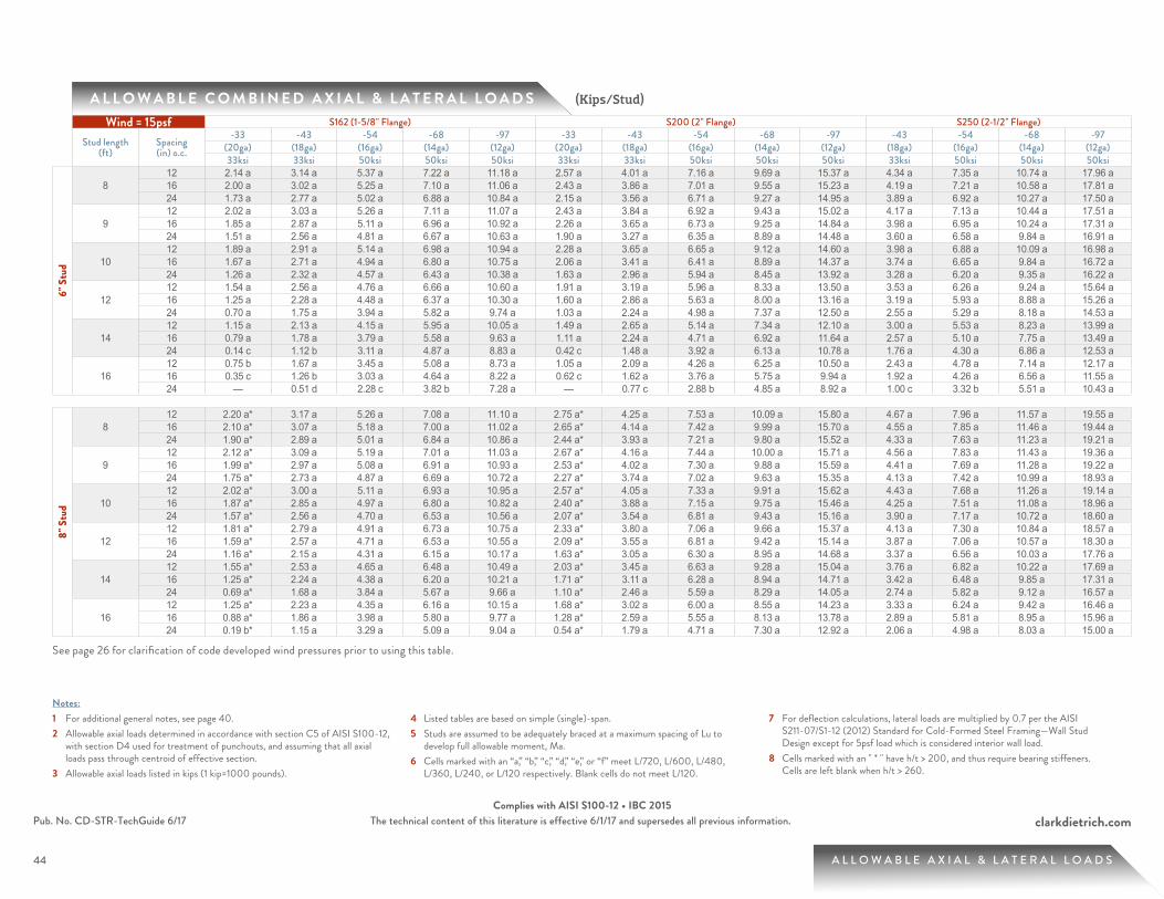
44
clarkdietrich.comPub. No. CD-STR-TechGuide 6/17 The technical content of this literature is effective 6/1/17 and supersedes all previous information.Complies with AISI S100-12 • IBC 2015
44
A L L O W A B L E C O M B I N E D A X I A L & L A T E R A L L O A D S
A L L O W A B L E A X I A L & L A T E R A L L O A D S
(Kips/Stud)
Notes:1 For additional general notes, see page 40.2 Allowable axial loads determined in accordance with section C5 of AISI S100-12,
with section D4 used for treatment of punchouts, and assuming that all axial loads pass through centroid of effective section.
3 Allowable axial loads listed in kips (1 kip=1000 pounds).
4 Listed tables are based on simple (single)-span.5 Studs are assumed to be adequately braced at a maximum spacing of Lu to
develop full allowable moment, Ma.6 Cells marked with an “a,” “b,” “c,” “d,” “e,” or “f” meet L/720, L/600, L/480,
L/360, L/240, or L/120 respectively. Blank cells do not meet L/120.
7 For deflection calculations, lateral loads are multiplied by 0.7 per the AISI S211-07/S1-12 (2012) Standard for Cold-Formed Steel Framing—Wall Stud Design except for 5psf load which is considered interior wall load.
8 Cells marked with an " * " have h/t > 200, and thus require bearing stiffeners. Cells are left blank when h/t > 260.
See page 26 for clarification of code developed wind pressures prior to using this table.
Wind = 15psf S162 (1-5/8" Flange) S200 (2" Flange) S250 (2-1/2" Flange)
Stud length (ft)
Spacing (in) o.c.
-33 -43 -54 -68 -97 -33 -43 -54 -68 -97 -43 -54 -68 -97(20ga) (18ga) (16ga) (14ga) (12ga) (20ga) (18ga) (16ga) (14ga) (12ga) (18ga) (16ga) (14ga) (12ga)33ksi 33ksi 50ksi 50ksi 50ksi 33ksi 33ksi 50ksi 50ksi 50ksi 33ksi 50ksi 50ksi 50ksi
6" S
tud
812 2.14 a 3.14 a 5.37 a 7.22 a 11.18 a 2.57 a 4.01 a 7.16 a 9.69 a 15.37 a 4.34 a 7.35 a 10.74 a 17.96 a 16 2.00 a 3.02 a 5.25 a 7.10 a 11.06 a 2.43 a 3.86 a 7.01 a 9.55 a 15.23 a 4.19 a 7.21 a 10.58 a 17.81 a 24 1.73 a 2.77 a 5.02 a 6.88 a 10.84 a 2.15 a 3.56 a 6.71 a 9.27 a 14.95 a 3.89 a 6.92 a 10.27 a 17.50 a
912 2.02 a 3.03 a 5.26 a 7.11 a 11.07 a 2.43 a 3.84 a 6.92 a 9.43 a 15.02 a 4.17 a 7.13 a 10.44 a 17.51 a 16 1.85 a 2.87 a 5.11 a 6.96 a 10.92 a 2.26 a 3.65 a 6.73 a 9.25 a 14.84 a 3.98 a 6.95 a 10.24 a 17.31 a 24 1.51 a 2.56 a 4.81 a 6.67 a 10.63 a 1.90 a 3.27 a 6.35 a 8.89 a 14.48 a 3.60 a 6.58 a 9.84 a 16.91 a
1012 1.89 a 2.91 a 5.14 a 6.98 a 10.94 a 2.28 a 3.65 a 6.65 a 9.12 a 14.60 a 3.98 a 6.88 a 10.09 a 16.98 a 16 1.67 a 2.71 a 4.94 a 6.80 a 10.75 a 2.06 a 3.41 a 6.41 a 8.89 a 14.37 a 3.74 a 6.65 a 9.84 a 16.72 a 24 1.26 a 2.32 a 4.57 a 6.43 a 10.38 a 1.63 a 2.96 a 5.94 a 8.45 a 13.92 a 3.28 a 6.20 a 9.35 a 16.22 a
1212 1.54 a 2.56 a 4.76 a 6.66 a 10.60 a 1.91 a 3.19 a 5.96 a 8.33 a 13.50 a 3.53 a 6.26 a 9.24 a 15.64 a 16 1.25 a 2.28 a 4.48 a 6.37 a 10.30 a 1.60 a 2.86 a 5.63 a 8.00 a 13.16 a 3.19 a 5.93 a 8.88 a 15.26 a 24 0.70 a 1.75 a 3.94 a 5.82 a 9.74 a 1.03 a 2.24 a 4.98 a 7.37 a 12.50 a 2.55 a 5.29 a 8.18 a 14.53 a
1412 1.15 a 2.13 a 4.15 a 5.95 a 10.05 a 1.49 a 2.65 a 5.14 a 7.34 a 12.10 a 3.00 a 5.53 a 8.23 a 13.99 a 16 0.79 a 1.78 a 3.79 a 5.58 a 9.63 a 1.11 a 2.24 a 4.71 a 6.92 a 11.64 a 2.57 a 5.10 a 7.75 a 13.49 a 24 0.14 c 1.12 b 3.11 a 4.87 a 8.83 a 0.42 c 1.48 a 3.92 a 6.13 a 10.78 a 1.76 a 4.30 a 6.86 a 12.53 a
1612 0.75 b 1.67 a 3.45 a 5.08 a 8.73 a 1.05 a 2.09 a 4.26 a 6.25 a 10.50 a 2.43 a 4.78 a 7.14 a 12.17 a 16 0.35 c 1.26 b 3.03 a 4.64 a 8.22 a 0.62 c 1.62 a 3.76 a 5.75 a 9.94 a 1.92 a 4.26 a 6.56 a 11.55 a 24 — 0.51 d 2.28 c 3.82 b 7.28 a — 0.77 c 2.88 b 4.85 a 8.92 a 1.00 c 3.32 b 5.51 a 10.43 a
8" S
tud
812 2.20 a* 3.17 a 5.26 a 7.08 a 11.10 a 2.75 a* 4.25 a 7.53 a 10.09 a 15.80 a 4.67 a 7.96 a 11.57 a 19.55 a 16 2.10 a* 3.07 a 5.18 a 7.00 a 11.02 a 2.65 a* 4.14 a 7.42 a 9.99 a 15.70 a 4.55 a 7.85 a 11.46 a 19.44 a 24 1.90 a* 2.89 a 5.01 a 6.84 a 10.86 a 2.44 a* 3.93 a 7.21 a 9.80 a 15.52 a 4.33 a 7.63 a 11.23 a 19.21 a
912 2.12 a* 3.09 a 5.19 a 7.01 a 11.03 a 2.67 a* 4.16 a 7.44 a 10.00 a 15.71 a 4.56 a 7.83 a 11.43 a 19.36 a 16 1.99 a* 2.97 a 5.08 a 6.91 a 10.93 a 2.53 a* 4.02 a 7.30 a 9.88 a 15.59 a 4.41 a 7.69 a 11.28 a 19.22 a 24 1.75 a* 2.73 a 4.87 a 6.69 a 10.72 a 2.27 a* 3.74 a 7.02 a 9.63 a 15.35 a 4.13 a 7.42 a 10.99 a 18.93 a
1012 2.02 a* 3.00 a 5.11 a 6.93 a 10.95 a 2.57 a* 4.05 a 7.33 a 9.91 a 15.62 a 4.43 a 7.68 a 11.26 a 19.14 a 16 1.87 a* 2.85 a 4.97 a 6.80 a 10.82 a 2.40 a* 3.88 a 7.15 a 9.75 a 15.46 a 4.25 a 7.51 a 11.08 a 18.96 a 24 1.57 a* 2.56 a 4.70 a 6.53 a 10.56 a 2.07 a* 3.54 a 6.81 a 9.43 a 15.16 a 3.90 a 7.17 a 10.72 a 18.60 a
1212 1.81 a* 2.79 a 4.91 a 6.73 a 10.75 a 2.33 a* 3.80 a 7.06 a 9.66 a 15.37 a 4.13 a 7.30 a 10.84 a 18.57 a 16 1.59 a* 2.57 a 4.71 a 6.53 a 10.55 a 2.09 a* 3.55 a 6.81 a 9.42 a 15.14 a 3.87 a 7.06 a 10.57 a 18.30 a 24 1.16 a* 2.15 a 4.31 a 6.15 a 10.17 a 1.63 a* 3.05 a 6.30 a 8.95 a 14.68 a 3.37 a 6.56 a 10.03 a 17.76 a
1412 1.55 a* 2.53 a 4.65 a 6.48 a 10.49 a 2.03 a* 3.45 a 6.63 a 9.28 a 15.04 a 3.76 a 6.82 a 10.22 a 17.69 a 16 1.25 a* 2.24 a 4.38 a 6.20 a 10.21 a 1.71 a* 3.11 a 6.28 a 8.94 a 14.71 a 3.42 a 6.48 a 9.85 a 17.31 a 24 0.69 a* 1.68 a 3.84 a 5.67 a 9.66 a 1.10 a* 2.46 a 5.59 a 8.29 a 14.05 a 2.74 a 5.82 a 9.12 a 16.57 a
1612 1.25 a* 2.23 a 4.35 a 6.16 a 10.15 a 1.68 a* 3.02 a 6.00 a 8.55 a 14.23 a 3.33 a 6.24 a 9.42 a 16.46 a 16 0.88 a* 1.86 a 3.98 a 5.80 a 9.77 a 1.28 a* 2.59 a 5.55 a 8.13 a 13.78 a 2.89 a 5.81 a 8.95 a 15.96 a 24 0.19 b* 1.15 a 3.29 a 5.09 a 9.04 a 0.54 a* 1.79 a 4.71 a 7.30 a 12.92 a 2.06 a 4.98 a 8.03 a 15.00 a
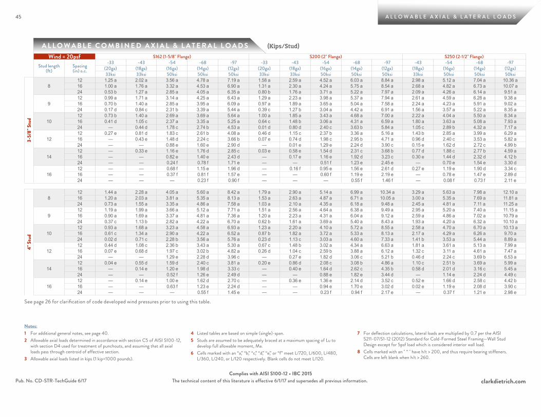
45
clarkdietrich.comPub. No. CD-STR-TechGuide 6/17 The technical content of this literature is effective 6/1/17 and supersedes all previous information.Complies with AISI S100-12 • IBC 2015
45
A L L O W A B L E C O M B I N E D A X I A L & L A T E R A L L O A D S
A L L O W A B L E A X I A L & L A T E R A L L O A D S
(Kips/Stud)
Notes:1 For additional general notes, see page 40.2 Allowable axial loads determined in accordance with section C5 of AISI S100-12,
with section D4 used for treatment of punchouts, and assuming that all axial loads pass through centroid of effective section.
3 Allowable axial loads listed in kips (1 kip=1000 pounds).
4 Listed tables are based on simple (single)-span.5 Studs are assumed to be adequately braced at a maximum spacing of Lu to
develop full allowable moment, Ma.6 Cells marked with an “a,” “b,” “c,” “d,” “e,” or “f” meet L/720, L/600, L/480,
L/360, L/240, or L/120 respectively. Blank cells do not meet L/120.
7 For deflection calculations, lateral loads are multiplied by 0.7 per the AISI S211-07/S1-12 (2012) Standard for Cold-Formed Steel Framing—Wall Stud Design except for 5psf load which is considered interior wall load.
8 Cells marked with an " * " have h/t > 200, and thus require bearing stiffeners. Cells are left blank when h/t > 260.
See page 26 for clarification of code developed wind pressures prior to using this table.
Wind = 20psf S162 (1-5/8" Flange) S200 (2" Flange) S250 (2-1/2" Flange)
Stud length (ft)
Spacing (in) o.c.
-33 -43 -54 -68 -97 -33 -43 -54 -68 -97 -43 -54 -68 -97(20ga) (18ga) (16ga) (14ga) (12ga) (20ga) (18ga) (16ga) (14ga) (12ga) (18ga) (16ga) (14ga) (12ga)33ksi 33ksi 50ksi 50ksi 50ksi 33ksi 33ksi 50ksi 50ksi 50ksi 33ksi 50ksi 50ksi 50ksi
3-5/
8" S
tud
812 1.25 a 2.02 a 3.56 a 4.78 a 7.19 a 1.58 a 2.59 a 4.52 a 6.03 a 8.84 a 2.98 a 5.12 a 7.04 a 10.36 a 16 1.00 a 1.76 a 3.32 a 4.53 a 6.90 a 1.31 a 2.30 a 4.24 a 5.75 a 8.54 a 2.68 a 4.82 a 6.73 a 10.07 a 24 0.53 b 1.27 a 2.85 a 4.05 a 6.35 a 0.80 b 1.76 a 3.71 a 5.22 a 7.97 a 2.09 a 4.26 a 6.14 a 9.51 a
912 0.99 a 1.71 a 3.14 a 4.25 a 6.43 a 1.29 a 2.23 a 3.98 a 5.37 a 7.94 a 2.61 a 4.59 a 6.28 a 9.38 a 16 0.70 b 1.40 a 2.85 a 3.95 a 6.09 a 0.97 a 1.89 a 3.65 a 5.04 a 7.58 a 2.24 a 4.23 a 5.91 a 9.02 a 24 0.17 d 0.84 c 2.31 b 3.39 a 5.44 a 0.39 c 1.27 b 3.04 a 4.42 a 6.91 a 1.56 a 3.57 a 5.22 a 8.35 a
1012 0.73 b 1.40 a 2.69 a 3.69 a 5.64 a 1.00 a 1.85 a 3.43 a 4.68 a 7.00 a 2.22 a 4.04 a 5.50 a 8.34 a 16 0.41 d 1.05 c 2.37 a 3.35 a 5.25 a 0.64 c 1.48 b 3.06 a 4.31 a 6.59 a 1.80 a 3.63 a 5.08 a 7.93 a 24 — 0.44 d 1.78 c 2.74 b 4.53 a 0.01 d 0.80 d 2.40 c 3.63 b 5.84 a 1.05 c 2.89 b 4.32 a 7.17 a
1212 0.27 e 0.81 d 1.83 c 2.61 b 4.08 a 0.46 d 1.15 c 2.37 b 3.36 a 5.16 a 1.43 b 2.85 a 3.99 a 6.29 a 16 — 0.43 e 1.48 d 2.24 c 3.66 b 0.07 e 0.74 d 1.98 c 2.95 b 4.71 a 0.96 d 2.40 c 3.53 a 5.82 a 24 — — 0.88 e 1.60 e 2.90 d — 0.01 e 1.29 e 2.24 d 3.90 c 0.15 e 1.62 d 2.72 c 4.99 b
1412 — 0.33 e 1.16 e 1.76 d 2.85 c 0.03 e 0.58 e 1.54 d 2.31 c 3.68 b 0.77 d 1.88 c 2.77 b 4.59 a 16 — — 0.82 e 1.40 e 2.43 d — 0.17 e 1.16 e 1.92 d 3.23 c 0.30 e 1.44 d 2.32 d 4.12 b 24 — — 0.24 f 0.78 f 1.71 e — — 0.51 f 1.23 e 2.45 e — 0.70 e 1.54 e 3.30 d
1612 — — 0.68 f 1.15 e 1.96 d — 0.16 f 0.95 e 1.56 e 2.61 d 0.27 e 1.19 e 1.90 d 3.34 c 16 — — 0.37 f 0.81 f 1.57 e — — 0.60 f 1.19 e 2.19 e — 0.78 e 1.47 e 2.89 d 24 — — — 0.23 f 0.90 f — — — 0.55 f 1.46 f — 0.08 f 0.73 f 2.11 e
4" S
tud
812 1.44 a 2.28 a 4.05 a 5.60 a 8.42 a 1.79 a 2.90 a 5.14 a 6.99 a 10.34 a 3.29 a 5.63 a 7.98 a 12.10 a 16 1.20 a 2.03 a 3.81 a 5.35 a 8.13 a 1.53 a 2.63 a 4.87 a 6.71 a 10.05 a 3.00 a 5.35 a 7.69 a 11.81 a 24 0.73 a 1.55 a 3.35 a 4.86 a 7.58 a 1.03 a 2.10 a 4.35 a 6.18 a 9.48 a 2.45 a 4.81 a 7.11 a 11.25 a
912 1.19 a 1.99 a 3.66 a 5.12 a 7.71 a 1.51 a 2.56 a 4.64 a 6.38 a 9.49 a 2.95 a 5.20 a 7.40 a 11.15 a 16 0.90 a 1.69 a 3.37 a 4.81 a 7.36 a 1.20 a 2.23 a 4.31 a 6.04 a 9.12 a 2.59 a 4.86 a 7.02 a 10.79 a 24 0.37 c 1.13 b 2.82 a 4.22 a 6.70 a 0.62 b 1.61 a 3.69 a 5.40 a 8.43 a 1.93 a 4.20 a 6.32 a 10.10 a
1012 0.93 a 1.68 a 3.23 a 4.58 a 6.93 a 1.23 a 2.20 a 4.10 a 5.72 a 8.55 a 2.58 a 4.70 a 6.70 a 10.13 a 16 0.61 c 1.34 a 2.90 a 4.22 a 6.52 a 0.87 b 1.82 a 3.72 a 5.33 a 8.13 a 2.17 a 4.29 a 6.26 a 9.70 a 24 0.02 d 0.71 c 2.28 b 3.56 a 5.76 a 0.23 d 1.13 c 3.03 a 4.60 a 7.33 a 1.41 b 3.53 a 5.44 a 8.89 a
1212 0.44 d 1.08 c 2.36 b 3.43 a 5.30 a 0.67 c 1.48 b 3.02 a 4.34 a 6.63 a 1.81 a 3.61 a 5.13 a 7.99 a 16 0.07 e 0.68 d 1.97 c 3.02 b 4.82 a 0.26 d 1.04 c 2.59 b 3.88 a 6.12 a 1.32 c 3.11 a 4.61 a 7.47 a 24 — — 1.29 e 2.28 d 3.96 c — 0.27 e 1.82 d 3.06 c 5.21 b 0.46 d 2.24 c 3.69 b 6.53 a
1412 0.04 e 0.55 d 1.59 d 2.40 c 3.81 a 0.20 e 0.86 d 2.08 c 3.08 b 4.86 a 1.10 c 2.51 b 3.69 a 5.99 a 16 — 0.14 e 1.20 e 1.98 d 3.33 c — 0.40 e 1.64 d 2.62 c 4.35 b 0.58 d 2.01 d 3.16 c 5.45 a 24 — — 0.52 f 1.26 e 2.49 d — — 0.88 e 1.82 e 3.44 d — 1.14 e 2.24 d 4.49 c
1612 — 0.14 e 1.00 e 1.62 d 2.70 c — 0.36 e 1.36 e 2.14 d 3.52 c 0.52 e 1.66 d 2.58 c 4.42 b 16 — — 0.63 f 1.23 e 2.24 d — — 0.94 e 1.70 e 3.02 d 0.02 e 1.19 e 2.08 d 3.90 c 24 — — — 0.55 f 1.45 e — — 0.23 f 0.94 f 2.17 e — 0.37 f 1.21 e 2.98 e

46
clarkdietrich.comPub. No. CD-STR-TechGuide 6/17 The technical content of this literature is effective 6/1/17 and supersedes all previous information.Complies with AISI S100-12 • IBC 2015
46
A L L O W A B L E C O M B I N E D A X I A L & L A T E R A L L O A D S
A L L O W A B L E A X I A L & L A T E R A L L O A D S
(Kips/Stud)
Notes:1 For additional general notes, see page 40.2 Allowable axial loads determined in accordance with section C5 of AISI S100-12,
with section D4 used for treatment of punchouts, and assuming that all axial loads pass through centroid of effective section.
3 Allowable axial loads listed in kips (1 kip=1000 pounds).
4 Listed tables are based on simple (single)-span.5 Studs are assumed to be adequately braced at a maximum spacing of Lu to
develop full allowable moment, Ma.6 Cells marked with an “a,” “b,” “c,” “d,” “e,” or “f” meet L/720, L/600, L/480,
L/360, L/240, or L/120 respectively. Blank cells do not meet L/120.
7 For deflection calculations, lateral loads are multiplied by 0.7 per the AISI S211-07/S1-12 (2012) Standard for Cold-Formed Steel Framing—Wall Stud Design except for 5psf load which is considered interior wall load.
8 Cells marked with an " * " have h/t > 200, and thus require bearing stiffeners. Cells are left blank when h/t > 260.
See page 26 for clarification of code developed wind pressures prior to using this table.
Wind = 20psf S162 (1-5/8" Flange) S200 (2" Flange) S250 (2-1/2" Flange)
Stud length (ft)
Spacing (in) o.c.
-33 -43 -54 -68 -97 -33 -43 -54 -68 -97 -43 -54 -68 -97(20ga) (18ga) (16ga) (14ga) (12ga) (20ga) (18ga) (16ga) (14ga) (12ga) (18ga) (16ga) (14ga) (12ga)33ksi 33ksi 50ksi 50ksi 50ksi 33ksi 33ksi 50ksi 50ksi 50ksi 33ksi 50ksi 50ksi 50ksi
6" S
tud
812 2.00 a 3.02 a 5.25 a 7.10 a 11.06 a 2.43 a 3.86 a 7.01 a 9.55 a 15.23 a 4.19 a 7.21 a 10.58 a 17.81 a 16 1.82 a 2.85 a 5.10 a 6.95 a 10.92 a 2.25 a 3.66 a 6.81 a 9.36 a 15.04 a 3.99 a 7.01 a 10.37 a 17.60 a 24 1.47 a 2.53 a 4.79 a 6.65 a 10.62 a 1.88 a 3.27 a 6.42 a 9.00 a 14.67 a 3.59 a 6.63 a 9.96 a 17.19 a
912 1.85 a 2.87 a 5.11 a 6.96 a 10.92 a 2.26 a 3.65 a 6.73 a 9.25 a 14.84 a 3.98 a 6.95 a 10.24 a 17.31 a 16 1.62 a 2.66 a 4.91 a 6.77 a 10.73 a 2.02 a 3.40 a 6.48 a 9.01 a 14.60 a 3.72 a 6.70 a 9.97 a 17.04 a 24 1.18 a 2.25 a 4.52 a 6.38 a 10.35 a 1.56 a 2.91 a 5.98 a 8.54 a 14.12 a 3.22 a 6.22 a 9.45 a 16.51 a
1012 1.67 a 2.71 a 4.94 a 6.80 a 10.75 a 2.06 a 3.41 a 6.41 a 8.89 a 14.37 a 3.74 a 6.65 a 9.84 a 16.72 a 16 1.40 a 2.45 a 4.69 a 6.55 a 10.50 a 1.77 a 3.11 a 6.10 a 8.59 a 14.07 a 3.43 a 6.35 a 9.51 a 16.38 a 24 0.86 a 1.94 a 4.20 a 6.06 a 10.02 a 1.22 a 2.51 a 5.49 a 8.02 a 13.47 a 2.82 a 5.76 a 8.86 a 15.72 a
1212 1.25 a 2.28 a 4.48 a 6.37 a 10.30 a 1.60 a 2.86 a 5.63 a 8.00 a 13.16 a 3.19 a 5.93 a 8.88 a 15.26 a 16 0.88 a 1.92 a 4.11 a 6.00 a 9.92 a 1.22 a 2.44 a 5.19 a 7.58 a 12.72 a 2.76 a 5.50 a 8.41 a 14.77 a 24 0.19 c 1.24 a 3.43 a 5.30 a 9.19 a 0.50 b 1.66 a 4.37 a 6.77 a 11.86 a 1.94 a 4.69 a 7.51 a 13.83 a
1412 0.79 a 1.78 a 3.79 a 5.58 a 9.63 a 1.11 a 2.24 a 4.71 a 6.92 a 11.64 a 2.57 a 5.10 a 7.75 a 13.49 a 16 0.35 c 1.33 b 3.33 a 5.10 a 9.09 a 0.64 b 1.73 a 4.18 a 6.38 a 11.06 a 2.02 a 4.56 a 7.15 a 12.85 a 24 — 0.52 d 2.50 c 4.21 a 8.09 a — 0.79 c 3.19 b 5.39 a 9.97 a 1.03 b 3.56 a 6.02 a 11.64 a
1612 0.35 c 1.26 b 3.03 a 4.64 a 8.22 a 0.62 c 1.62 a 3.76 a 5.75 a 9.94 a 1.92 a 4.26 a 6.56 a 11.55 a 16 — 0.75 d 2.52 c 4.08 a 7.58 a 0.10 d 1.04 c 3.16 b 5.14 a 9.25 a 1.29 b 3.62 a 5.85 a 10.79 a 24 — — 1.60 d 3.09 c 6.44 b — 0.01 d 2.09 d 4.03 c 8.01 a 0.17 d 2.48 c 4.57 b 9.41 a
8" S
tud
812 2.10 a* 3.07 a 5.18 a 7.00 a 11.02 a 2.65 a* 4.14 a 7.42 a 9.99 a 15.70 a 4.55 a 7.85 a 11.46 a 19.44 a 16 1.97 a* 2.95 a 5.07 a 6.89 a 10.91 a 2.51 a* 4.00 a 7.28 a 9.86 a 15.58 a 4.40 a 7.70 a 11.31 a 19.29 a 24 1.71 a* 2.70 a 4.84 a 6.67 a 10.70 a 2.23 a* 3.71 a 6.99 a 9.60 a 15.33 a 4.10 a 7.42 a 11.00 a 18.99 a
912 1.99 a* 2.97 a 5.08 a 6.91 a 10.93 a 2.53 a* 4.02 a 7.30 a 9.88 a 15.59 a 4.41 a 7.69 a 11.28 a 19.22 a 16 1.83 a* 2.81 a 4.94 a 6.77 a 10.79 a 2.36 a* 3.84 a 7.11 a 9.71 a 15.43 a 4.22 a 7.51 a 11.09 a 19.03 a 24 1.50 a* 2.50 a 4.65 a 6.49 a 10.51 a 2.01 a* 3.47 a 6.75 a 9.38 a 15.11 a 3.84 a 7.14 a 10.70 a 18.65 a
1012 1.87 a* 2.85 a 4.97 a 6.80 a 10.82 a 2.40 a* 3.88 a 7.15 a 9.75 a 15.46 a 4.25 a 7.51 a 11.08 a 18.96 a 16 1.67 a* 2.65 a 4.79 a 6.62 a 10.65 a 2.18 a* 3.65 a 6.93 a 9.54 a 15.26 a 4.02 a 7.28 a 10.84 a 18.72 a 24 1.27 a* 2.27 a 4.44 a 6.27 a 10.30 a 1.75 a* 3.20 a 6.47 a 9.12 a 14.86 a 3.55 a 6.83 a 10.35 a 18.24 a
1212 1.59 a* 2.57 a 4.71 a 6.53 a 10.55 a 2.09 a* 3.55 a 6.81 a 9.42 a 15.14 a 3.87 a 7.06 a 10.57 a 18.30 a 16 1.30 a* 2.29 a 4.44 a 6.27 a 10.29 a 1.78 a* 3.22 a 6.47 a 9.11 a 14.83 a 3.53 a 6.73 a 10.21 a 17.94 a 24 0.74 a* 1.74 a 3.93 a 5.76 a 9.78 a 1.17 a* 2.57 a 5.81 a 8.49 a 14.23 a 2.87 a 6.08 a 9.51 a 17.23 a
1412 1.25 a* 2.24 a 4.38 a 6.20 a 10.21 a 1.71 a* 3.11 a 6.28 a 8.94 a 14.71 a 3.42 a 6.48 a 9.85 a 17.31 a 16 0.87 a* 1.86 a 4.02 a 5.84 a 9.84 a 1.30 a* 2.67 a 5.82 a 8.51 a 14.27 a 2.96 a 6.04 a 9.36 a 16.81 a 24 0.15 b* 1.14 a 3.32 a 5.14 a 9.13 a 0.52 a* 1.83 a 4.94 a 7.66 a 13.41 a 2.10 a 5.19 a 8.42 a 15.84 a
1612 0.88 a* 1.86 a 3.98 a 5.80 a 9.77 a 1.28 a* 2.59 a 5.55 a 8.13 a 13.78 a 2.89 a 5.81 a 8.95 a 15.96 a 16 0.41 b* 1.38 a 3.52 a 5.32 a 9.28 a 0.78 a* 2.05 a 4.98 a 7.57 a 13.20 a 2.33 a 5.25 a 8.33 a 15.32 a 24 — 0.49 b 2.63 a 4.42 a 8.34 a — 1.03 a 3.91 a 6.52 a 12.09 a 1.28 a 4.19 a 7.15 a 14.08 a

47
clarkdietrich.comPub. No. CD-STR-TechGuide 6/17 The technical content of this literature is effective 6/1/17 and supersedes all previous information.Complies with AISI S100-12 • IBC 2015
47
A L L O W A B L E C O M B I N E D A X I A L & L A T E R A L L O A D S
A L L O W A B L E A X I A L & L A T E R A L L O A D S
(Kips/Stud)
Notes:1 For additional general notes, see page 40.2 Allowable axial loads determined in accordance with section C5 of AISI S100-12,
with section D4 used for treatment of punchouts, and assuming that all axial loads pass through centroid of effective section.
3 Allowable axial loads listed in kips (1 kip=1000 pounds).
4 Listed tables are based on simple (single)-span.5 Studs are assumed to be adequately braced at a maximum spacing of Lu to
develop full allowable moment, Ma.6 Cells marked with an “a,” “b,” “c,” “d,” “e,” or “f” meet L/720, L/600, L/480,
L/360, L/240, or L/120 respectively. Blank cells do not meet L/120.
7 For deflection calculations, lateral loads are multiplied by 0.7 per the AISI S211-07/S1-12 (2012) Standard for Cold-Formed Steel Framing—Wall Stud Design except for 5psf load which is considered interior wall load.
8 Cells marked with an " * " have h/t > 200, and thus require bearing stiffeners. Cells are left blank when h/t > 260.
See page 26 for clarification of code developed wind pressures prior to using this table.
Wind = 25psf S162 (1-5/8" Flange) S200 (2" Flange) S250 (2-1/2" Flange)
Stud length (ft)
Spacing (in) o.c.
-33 -43 -54 -68 -97 -33 -43 -54 -68 -97 -43 -54 -68 -97(20ga) (18ga) (16ga) (14ga) (12ga) (20ga) (18ga) (16ga) (14ga) (12ga) (18ga) (16ga) (14ga) (12ga)33ksi 33ksi 50ksi 50ksi 50ksi 33ksi 33ksi 50ksi 50ksi 50ksi 33ksi 50ksi 50ksi 50ksi
3-5/
8" S
tud
812 1.06 a 1.82 a 3.38 a 4.59 a 6.97 a 1.38 a 2.38 a 4.31 a 5.82 a 8.62 a 2.75 a 4.89 a 6.81 a 10.15 a 16 0.76 a 1.51 a 3.08 a 4.29 a 6.62 a 1.05 a 2.03 a 3.97 a 5.48 a 8.26 a 2.38 a 4.53 a 6.43 a 9.79 a 24 0.20 c 0.92 b 2.52 a 3.70 a 5.96 a 0.44 c 1.38 a 3.34 a 4.85 a 7.56 a 1.68 a 3.85 a 5.72 a 9.10 a
912 0.77 b 1.48 a 2.92 a 4.02 a 6.17 a 1.05 a 1.97 a 3.73 a 5.12 a 7.67 a 2.33 a 4.32 a 6.00 a 9.11 a 16 0.43 c 1.12 b 2.57 a 3.66 a 5.76 a 0.67 c 1.57 a 3.34 a 4.72 a 7.24 a 1.89 a 3.89 a 5.56 a 8.68 a 24 — 0.46 d 1.94 c 3.00 b 4.99 a — 0.84 c 2.62 b 3.99 a 6.43 a 1.09 b 3.10 a 4.74 a 7.87 a
1012 0.49 c 1.14 b 2.45 a 3.44 a 5.34 a 0.73 c 1.57 a 3.15 a 4.40 a 6.69 a 1.90 a 3.73 a 5.18 a 8.03 a 16 0.12 d 0.74 d 2.07 c 3.04 a 4.88 a 0.32 d 1.13 c 2.72 b 3.96 a 6.21 a 1.41 b 3.25 a 4.69 a 7.55 a 24 — 0.03 e 1.38 d 2.32 c 4.04 b — 0.34 d 1.95 d 3.17 c 5.32 a 0.54 d 2.38 c 3.80 b 6.64 a
1212 0.01 e 0.52 d 1.57 d 2.33 c 3.76 a 0.16 e 0.84 d 2.07 c 3.05 b 4.82 a 1.07 c 2.51 b 3.64 a 5.93 a 16 — 0.09 e 1.17 e 1.91 d 3.27 c — 0.36 e 1.62 d 2.58 c 4.29 b 0.54 d 1.99 d 3.11 c 5.39 a 24 — — 0.47 f 1.17 e 2.40 d — — 0.83 e 1.77 e 3.36 d — 1.10 e 2.18 d 4.42 c
1412 — 0.05 f 0.90 e 1.49 e 2.53 d — 0.27 e 1.25 e 2.01 d 3.34 c 0.41 e 1.55 d 2.43 c 4.23 b 16 — — 0.52 f 1.08 e 2.06 e — — 0.82 e 1.56 e 2.83 d — 1.05 e 1.91 d 3.69 c 24 — — — 0.37 f 1.24 f — — 0.08 f 0.78 f 1.94 e — 0.21 f 1.02 e 2.75 e
1612 — — 0.44 f 0.89 f 1.67 e — — 0.68 f 1.28 e 2.29 d — 0.88 e 1.57 e 3.00 d 16 — — 0.08 f 0.51 f 1.22 f — — 0.28 f 0.86 f 1.81 e — 0.41 f 1.08 e 2.48 e 24 — — — — 0.47 f — — — 0.13 f 0.98 f — — 0.25 f 1.59 f
4" S
tud
812 1.26 a 2.09 a 3.87 a 5.41 a 8.20 a 1.59 a 2.70 a 4.94 a 6.78 a 10.12 a 3.07 a 5.42 a 7.76 a 11.89 a 16 0.96 a 1.78 a 3.58 a 5.10 a 7.86 a 1.28 a 2.36 a 4.60 a 6.45 a 9.76 a 2.72 a 5.08 a 7.39 a 11.53 a 24 0.41 b 1.21 a 3.02 a 4.51 a 7.19 a 0.68 b 1.73 a 3.97 a 5.80 a 9.06 a 2.05 a 4.42 a 6.69 a 10.84 a
912 0.97 a 1.76 a 3.44 a 4.88 a 7.45 a 1.28 a 2.31 a 4.39 a 6.13 a 9.21 a 2.68 a 4.94 a 7.12 a 10.88 a 16 0.63 b 1.40 a 3.09 a 4.51 a 7.02 a 0.91 a 1.92 a 3.99 a 5.72 a 8.77 a 2.26 a 4.52 a 6.66 a 10.44 a 24 — 0.73 c 2.43 b 3.81 a 6.22 a 0.22 c 1.18 b 3.25 a 4.95 a 7.93 a 1.47 a 3.74 a 5.81 a 9.60 a
1012 0.68 b 1.42 a 2.98 a 4.31 a 6.62 a 0.96 a 1.92 a 3.82 a 5.42 a 8.23 a 2.27 a 4.39 a 6.37 a 9.81 a 16 0.30 d 1.02 b 2.58 a 3.88 a 6.13 a 0.54 c 1.47 b 3.37 a 4.95 a 7.72 a 1.78 a 3.90 a 5.84 a 9.29 a 24 — 0.28 d 1.86 c 3.10 b 5.23 a — 0.65 d 2.55 c 4.09 b 6.77 a 0.90 c 3.01 b 4.88 a 8.33 a
1212 0.16 d 0.77 d 2.07 c 3.12 b 4.94 a 0.36 d 1.15 c 2.70 b 3.99 a 6.24 a 1.44 b 3.23 a 4.74 a 7.60 a 16 — 0.32 e 1.62 d 2.64 c 4.38 b — 0.64 d 2.19 c 3.46 b 5.65 a 0.87 d 2.66 c 4.13 a 6.98 a 24 — — 0.83 e 1.79 e 3.39 d — — 1.31 e 2.51 d 4.59 c — 1.66 d 3.07 c 5.88 b
1412 — 0.24 e 1.29 e 2.08 d 3.45 c — 0.51 e 1.74 d 2.73 c 4.47 b 0.71 d 2.13 c 3.29 b 5.58 a 16 — — 0.84 e 1.61 e 2.90 d — — 1.24 e 2.20 d 3.88 c 0.12 e 1.56 d 2.68 d 4.95 b 24 — — 0.08 f 0.78 f 1.94 e — — 0.38 f 1.29 e 2.84 e — 0.58 e 1.64 e 3.86 d
1612 — — 0.72 e 1.32 e 2.35 d — 0.02 f 1.04 e 1.80 e 3.14 d 0.14 e 1.30 e 2.20 d 4.02 c 16 — — 0.29 f 0.87 f 1.83 e — — 0.57 f 1.30 e 2.57 e — 0.76 e 1.63 e 3.42 d 24 — — — 0.10 f 0.94 f — — — 0.45 f 1.60 f — — 0.65 f 2.38 e

48
clarkdietrich.comPub. No. CD-STR-TechGuide 6/17 The technical content of this literature is effective 6/1/17 and supersedes all previous information.Complies with AISI S100-12 • IBC 2015
48
A L L O W A B L E C O M B I N E D A X I A L & L A T E R A L L O A D S
A L L O W A B L E A X I A L & L A T E R A L L O A D S
(Kips/Stud)
Notes:1 For additional general notes, see page 40.2 Allowable axial loads determined in accordance with section C5 of AISI S100-12,
with section D4 used for treatment of punchouts, and assuming that all axial loads pass through centroid of effective section.
3 Allowable axial loads listed in kips (1 kip=1000 pounds).
4 Listed tables are based on simple (single)-span.5 Studs are assumed to be adequately braced at a maximum spacing of Lu to
develop full allowable moment, Ma.6 Cells marked with an “a,” “b,” “c,” “d,” “e,” or “f” meet L/720, L/600, L/480,
L/360, L/240, or L/120 respectively. Blank cells do not meet L/120.
7 For deflection calculations, lateral loads are multiplied by 0.7 per the AISI S211-07/S1-12 (2012) Standard for Cold-Formed Steel Framing—Wall Stud Design except for 5psf load which is considered interior wall load.
8 Cells marked with an " * " have h/t > 200, and thus require bearing stiffeners. Cells are left blank when h/t > 260.
See page 26 for clarification of code developed wind pressures prior to using this table.
Wind = 25psf S162 (1-5/8" Flange) S200 (2" Flange) S250 (2-1/2" Flange)
Stud length (ft)
Spacing (in) o.c.
-33 -43 -54 -68 -97 -33 -43 -54 -68 -97 -43 -54 -68 -97(20ga) (18ga) (16ga) (14ga) (12ga) (20ga) (18ga) (16ga) (14ga) (12ga) (18ga) (16ga) (14ga) (12ga)33ksi 33ksi 50ksi 50ksi 50ksi 33ksi 33ksi 50ksi 50ksi 50ksi 33ksi 50ksi 50ksi 50ksi
6" S
tud
812 1.87 a 2.89 a 5.14 a 6.99 a 10.95 a 2.29 a 3.71 a 6.86 a 9.41 a 15.09 a 4.04 a 7.06 a 10.43 a 17.65 a 16 1.64 a 2.69 a 4.94 a 6.80 a 10.77 a 2.06 a 3.46 a 6.61 a 9.18 a 14.86 a 3.79 a 6.82 a 10.17 a 17.39 a 24 1.21 a 2.28 a 4.56 a 6.43 a 10.40 a 1.60 a 2.98 a 6.12 a 8.72 a 14.40 a 3.29 a 6.35 a 9.65 a 16.88 a
912 1.68 a 2.71 a 4.96 a 6.82 a 10.78 a 2.08 a 3.46 a 6.54 a 9.07 a 14.66 a 3.79 a 6.76 a 10.04 a 17.11 a 16 1.40 a 2.45 a 4.71 a 6.57 a 10.54 a 1.79 a 3.15 a 6.23 a 8.78 a 14.36 a 3.47 a 6.46 a 9.71 a 16.78 a 24 0.86 a 1.95 a 4.22 a 6.09 a 10.06 a 1.23 a 2.55 a 5.62 a 8.19 a 13.77 a 2.85 a 5.87 a 9.06 a 16.12 a
1012 1.46 a 2.51 a 4.75 a 6.61 a 10.57 a 1.84 a 3.18 a 6.17 a 8.67 a 14.14 a 3.51 a 6.42 a 9.59 a 16.47 a 16 1.13 a 2.19 a 4.44 a 6.30 a 10.26 a 1.49 a 2.81 a 5.79 a 8.30 a 13.77 a 3.12 a 6.05 a 9.18 a 16.05 a 24 0.48 a 1.58 a 3.84 a 5.71 a 9.66 a 0.82 a 2.08 a 5.05 a 7.59 a 13.03 a 2.38 a 5.32 a 8.39 a 15.24 a
1212 0.97 a 2.01 a 4.20 a 6.09 a 10.02 a 1.31 a 2.55 a 5.30 a 7.68 a 12.83 a 2.87 a 5.61 a 8.53 a 14.89 a 16 0.53 b 1.58 a 3.77 a 5.64 a 9.55 a 0.85 a 2.04 a 4.78 a 7.17 a 12.29 a 2.34 a 5.09 a 7.95 a 14.29 a 24 — 0.76 b 2.94 a 4.79 a 8.66 a — 1.10 b 3.79 a 6.20 a 11.25 a 1.36 a 4.11 a 6.86 a 13.15 a
1412 0.45 c 1.44 a 3.44 a 5.21 a 9.22 a 0.76 b 1.86 a 4.31 a 6.51 a 11.20 a 2.16 a 4.69 a 7.30 a 13.00 a 16 — 0.91 c 2.90 b 4.65 a 8.58 a 0.21 c 1.25 b 3.67 a 5.87 a 10.50 a 1.51 a 4.05 a 6.57 a 12.23 a 24 — — 1.92 d 3.60 c 7.39 a — 0.15 d 2.52 c 4.70 b 9.21 a 0.34 c 2.86 b 5.24 a 10.80 a
1612 — 0.87 c 2.64 b 4.22 a 7.74 a 0.23 d 1.18 c 3.31 a 5.29 a 9.42 a 1.44 b 3.78 a 6.02 a 10.97 a 16 — 0.29 d 2.04 d 3.57 c 6.99 a — 0.50 d 2.61 c 4.57 b 8.61 a 0.71 c 3.03 b 5.18 a 10.08 a 24 — — 0.98 e 2.42 d 5.67 c — — 1.37 d 3.28 d 7.16 b — 1.70 d 3.70 c 8.47 b
8" S
tud
812 2.00 a* 2.98 a 5.09 a 6.92 a 10.94 a 2.55 a* 4.03 a 7.31 a 9.89 a 15.61 a 4.44 a 7.74 a 11.34 a 19.32 a 16 1.84 a* 2.82 a 4.95 a 6.78 a 10.81 a 2.37 a* 3.85 a 7.14 a 9.73 a 15.45 a 4.25 a 7.56 a 11.15 a 19.14 a 24 1.52 a* 2.52 a 4.67 a 6.51 a 10.54 a 2.03 a* 3.49 a 6.78 a 9.41 a 15.14 a 3.88 a 7.21 a 10.78 a 18.77 a
912 1.87 a* 2.85 a 4.97 a 6.80 a 10.82 a 2.40 a* 3.88 a 7.16 a 9.75 a 15.47 a 4.27 a 7.55 a 11.14 a 19.08 a 16 1.66 a* 2.65 a 4.79 a 6.62 a 10.65 a 2.18 a* 3.65 a 6.93 a 9.54 a 15.27 a 4.03 a 7.33 a 10.90 a 18.84 a 24 1.26 a* 2.26 a 4.44 a 6.28 a 10.31 a 1.75 a* 3.20 a 6.48 a 9.13 a 14.87 a 3.56 a 6.87 a 10.41 a 18.36 a
1012 1.72 a* 2.70 a 4.84 a 6.67 a 10.69 a 2.24 a* 3.71 a 6.98 a 9.59 a 15.31 a 4.08 a 7.34 a 10.90 a 18.78 a 16 1.47 a* 2.46 a 4.61 a 6.45 a 10.47 a 1.97 a* 3.42 a 6.70 a 9.33 a 15.06 a 3.78 a 7.05 a 10.59 a 18.48 a 24 0.97 a* 1.98 a 4.17 a 6.01 a 10.04 a 1.43 a* 2.86 a 6.13 a 8.81 a 14.56 a 3.20 a 6.50 a 9.99 a 17.89 a
1212 1.37 a* 2.36 a 4.51 a 6.34 a 10.36 a 1.86 a* 3.30 a 6.55 a 9.19 a 14.91 a 3.62 a 6.81 a 10.30 a 18.03 a 16 1.02 a* 2.01 a 4.18 a 6.02 a 10.04 a 1.48 a* 2.89 a 6.13 a 8.80 a 14.53 a 3.20 a 6.40 a 9.86 a 17.58 a 24 0.33 a* 1.34 a 3.55 a 5.39 a 9.40 a 0.73 a* 2.10 a 5.32 a 8.04 a 13.78 a 2.39 a 5.61 a 8.99 a 16.70 a
1412 0.97 a* 1.96 a 4.11 a 5.93 a 9.94 a 1.40 a* 2.78 a 5.93 a 8.61 a 14.38 a 3.08 a 6.15 a 9.48 a 16.94 a 16 0.51 a* 1.49 a 3.66 a 5.49 a 9.48 a 0.91 a* 2.24 a 5.37 a 8.08 a 13.84 a 2.53 a 5.61 a 8.89 a 16.32 a 24 — 0.62 a 2.82 a 4.64 a 8.60 a — 1.22 a 4.30 a 7.05 a 12.79 a 1.47 a 4.57 a 7.74 a 15.13 a
1612 0.53 a* 1.50 a 3.63 a 5.44 a 9.40 a 0.91 a* 2.18 a 5.12 a 7.71 a 13.34 a 2.47 a 5.39 a 8.48 a 15.48 a 16 — 0.93 a 3.07 a 4.87 a 8.80 a 0.31 b* 1.53 a 4.44 a 7.04 a 12.64 a 1.79 a 4.71 a 7.73 a 14.69 a 24 — — 2.01 b 3.78 a 7.66 a — 0.32 c 3.15 a 5.77 a 11.30 a 0.53 b 3.45 a 6.32 a 13.19 a

49
clarkdietrich.comPub. No. CD-STR-TechGuide 6/17 The technical content of this literature is effective 6/1/17 and supersedes all previous information.Complies with AISI S100-12 • IBC 2015
49
A L L O W A B L E C O M B I N E D A X I A L & L A T E R A L L O A D S
A L L O W A B L E A X I A L & L A T E R A L L O A D S
(Kips/Stud)
Notes:1 For additional general notes, see page 40.2 Allowable axial loads determined in accordance with section C5 of AISI S100-12,
with section D4 used for treatment of punchouts, and assuming that all axial loads pass through centroid of effective section.
3 Allowable axial loads listed in kips (1 kip=1000 pounds).
4 Listed tables are based on simple (single)-span.5 Studs are assumed to be adequately braced at a maximum spacing of Lu to
develop full allowable moment, Ma.6 Cells marked with an “a,” “b,” “c,” “d,” “e,” or “f” meet L/720, L/600, L/480,
L/360, L/240, or L/120 respectively. Blank cells do not meet L/120.
7 For deflection calculations, lateral loads are multiplied by 0.7 per the AISI S211-07/S1-12 (2012) Standard for Cold-Formed Steel Framing—Wall Stud Design except for 5psf load which is considered interior wall load.
8 Cells marked with an " * " have h/t > 200, and thus require bearing stiffeners. Cells are left blank when h/t > 260.
See page 26 for clarification of code developed wind pressures prior to using this table.
Wind = 30psf S162 (1-5/8" Flange) S200 (2" Flange) S250 (2-1/2" Flange)
Stud length (ft)
Spacing (in) o.c.
-33 -43 -54 -68 -97 -33 -43 -54 -68 -97 -43 -54 -68 -97(20ga) (18ga) (16ga) (14ga) (12ga) (20ga) (18ga) (16ga) (14ga) (12ga) (18ga) (16ga) (14ga) (12ga)33ksi 33ksi 50ksi 50ksi 50ksi 33ksi 33ksi 50ksi 50ksi 50ksi 33ksi 50ksi 50ksi 50ksi
3-5/
8" S
tud
812 0.88 a 1.63 a 3.20 a 4.41 a 6.76 a 1.18 a 2.17 a 4.11 a 5.62 a 8.40 a 2.53 a 4.68 a 6.58 a 9.93 a 16 0.53 b 1.27 a 2.85 a 4.05 a 6.35 a 0.80 b 1.76 a 3.71 a 5.22 a 7.97 a 2.09 a 4.26 a 6.14 a 9.51 a 24 — 0.60 c 2.21 b 3.37 a 5.58 a 0.10 d 1.02 b 2.98 a 4.48 a 7.17 a 1.29 b 3.47 a 5.31 a 8.71 a
912 0.56 c 1.26 a 2.71 a 3.80 a 5.92 a 0.82 b 1.73 a 3.50 a 4.88 a 7.41 a 2.07 a 4.06 a 5.74 a 8.85 a 16 0.17 d 0.84 c 2.31 b 3.39 a 5.44 a 0.39 c 1.27 b 3.04 a 4.42 a 6.91 a 1.56 a 3.57 a 5.22 a 8.35 a 24 — 0.09 d 1.58 d 2.62 c 4.56 a — 0.44 d 2.22 c 3.58 b 5.98 a 0.65 c 2.66 b 4.28 a 7.41 a
1012 0.26 d 0.89 c 2.22 b 3.19 a 5.06 a 0.48 c 1.30 b 2.89 a 4.13 a 6.40 a 1.60 a 3.44 a 4.88 a 7.74 a 16 — 0.44 d 1.78 c 2.74 b 4.53 a 0.01 d 0.80 d 2.40 c 3.63 b 5.84 a 1.05 c 2.89 b 4.32 a 7.17 a 24 — — 1.01 e 1.92 d 3.58 c — — 1.53 d 2.73 d 4.83 b 0.06 d 1.91 d 3.30 c 6.14 a
1212 — 0.26 e 1.32 d 2.07 d 3.46 b — 0.54 d 1.80 d 2.77 c 4.49 a 0.74 d 2.19 c 3.32 b 5.60 a 16 — — 0.88 e 1.60 e 2.90 d — 0.01 e 1.29 e 2.24 d 3.90 c 0.15 e 1.62 d 2.72 c 4.99 b 24 — — 0.10 f 0.77 f 1.94 e — — 0.41 f 1.33 e 2.86 d — 0.62 e 1.68 e 3.89 d
1412 — — 0.67 f 1.23 e 2.24 d — — 0.99 e 1.74 e 3.03 d 0.08 e 1.24 e 2.11 d 3.90 c 16 — — 0.24 f 0.78 f 1.71 e — — 0.51 f 1.23 e 2.45 e — 0.70 e 1.54 e 3.30 d 24 — — — — 0.80 f — — — 0.37 f 1.47 f — — 0.55 f 2.24 e
1612 — — 0.22 f 0.65 f 1.39 e — — 0.43 f 1.02 f 1.99 e — 0.59 f 1.27 e 2.68 d 16 — — — 0.23 f 0.90 f — — — 0.55 f 1.46 f — 0.08 f 0.73 f 2.11 e 24 — — — — 0.07 f — — — — 0.54 f — — — 1.12 f
4" S
tud
812 1.08 a 1.90 a 3.69 a 5.22 a 7.99 a 1.40 a 2.49 a 4.73 a 6.58 a 9.90 a 2.86 a 5.21 a 7.54 a 11.67 a 16 0.73 a 1.55 a 3.35 a 4.86 a 7.58 a 1.03 a 2.10 a 4.35 a 6.18 a 9.48 a 2.45 a 4.81 a 7.11 a 11.25 a 24 0.10 c 0.88 b 2.70 a 4.18 a 6.80 a 0.34 c 1.37 a 3.61 a 5.42 a 8.66 a 1.67 a 4.05 a 6.28 a 10.43 a
912 0.76 b 1.54 a 3.23 a 4.66 a 7.19 a 1.05 a 2.07 a 4.15 a 5.88 a 8.94 a 2.42 a 4.69 a 6.84 a 10.62 a 16 0.37 c 1.13 b 2.82 a 4.22 a 6.70 a 0.62 b 1.61 a 3.69 a 5.40 a 8.43 a 1.93 a 4.20 a 6.32 a 10.10 a 24 — 0.36 d 2.07 c 3.42 b 5.77 a — 0.77 c 2.84 b 4.51 a 7.45 a 1.03 b 3.29 a 5.33 a 9.12 a
1012 0.45 c 1.18 b 2.74 a 4.05 a 6.33 a 0.70 b 1.64 a 3.54 a 5.14 a 7.92 a 1.97 a 4.09 a 6.05 a 9.49 a 16 0.02 d 0.71 c 2.28 b 3.56 a 5.76 a 0.23 d 1.13 c 3.03 a 4.60 a 7.33 a 1.41 b 3.53 a 5.44 a 8.89 a 24 — — 1.46 d 2.67 c 4.73 b — 0.21 d 2.10 c 3.61 c 6.24 a 0.41 d 2.52 c 4.34 b 7.79 a
1212 — 0.49 d 1.79 d 2.82 c 4.60 a 0.07 e 0.84 d 2.39 c 3.67 b 5.88 a 1.09 c 2.88 b 4.37 a 7.22 a 16 — — 1.29 e 2.28 d 3.96 c — 0.27 e 1.82 d 3.06 c 5.21 b 0.46 d 2.24 c 3.69 b 6.53 a 24 — — 0.41 f 1.33 e 2.86 d — — 0.84 e 2.01 e 4.02 d — 1.12 e 2.49 d 5.29 c
1412 — — 1.02 e 1.79 d 3.11 c — 0.19 e 1.44 e 2.41 d 4.11 c 0.35 e 1.78 d 2.92 c 5.20 b 16 — — 0.52 f 1.26 e 2.49 d — — 0.88 e 1.82 e 3.44 d — 1.14 e 2.24 d 4.49 c 24 — — — 0.35 f 1.43 e — — — 0.80 f 2.29 e — 0.06 f 1.09 e 3.27 e
1612 — — 0.46 f 1.05 e 2.03 e — — 0.75 f 1.50 e 2.79 d — 0.97 e 1.85 e 3.65 d 16 — — — 0.55 f 1.45 e — — 0.23 f 0.94 f 2.17 e — 0.37 f 1.21 e 2.98 e 24 — — — — 0.46 f — — — — 1.09 f — — 0.13 f 1.83 f
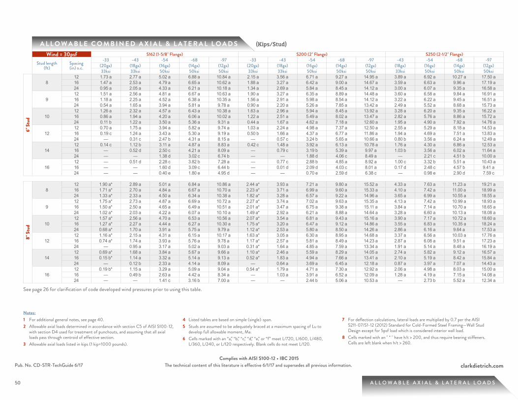
50
clarkdietrich.comPub. No. CD-STR-TechGuide 6/17 The technical content of this literature is effective 6/1/17 and supersedes all previous information.Complies with AISI S100-12 • IBC 2015
50
A L L O W A B L E C O M B I N E D A X I A L & L A T E R A L L O A D S
A L L O W A B L E A X I A L & L A T E R A L L O A D S
(Kips/Stud)
Notes:1 For additional general notes, see page 40.2 Allowable axial loads determined in accordance with section C5 of AISI S100-12,
with section D4 used for treatment of punchouts, and assuming that all axial loads pass through centroid of effective section.
3 Allowable axial loads listed in kips (1 kip=1000 pounds).
4 Listed tables are based on simple (single)-span.5 Studs are assumed to be adequately braced at a maximum spacing of Lu to
develop full allowable moment, Ma.6 Cells marked with an “a,” “b,” “c,” “d,” “e,” or “f” meet L/720, L/600, L/480,
L/360, L/240, or L/120 respectively. Blank cells do not meet L/120.
7 For deflection calculations, lateral loads are multiplied by 0.7 per the AISI S211-07/S1-12 (2012) Standard for Cold-Formed Steel Framing—Wall Stud Design except for 5psf load which is considered interior wall load.
8 Cells marked with an " * " have h/t > 200, and thus require bearing stiffeners. Cells are left blank when h/t > 260.
See page 26 for clarification of code developed wind pressures prior to using this table.
Wind = 30psf S162 (1-5/8" Flange) S200 (2" Flange) S250 (2-1/2" Flange)
Stud length (ft)
Spacing (in) o.c.
-33 -43 -54 -68 -97 -33 -43 -54 -68 -97 -43 -54 -68 -97(20ga) (18ga) (16ga) (14ga) (12ga) (20ga) (18ga) (16ga) (14ga) (12ga) (18ga) (16ga) (14ga) (12ga)33ksi 33ksi 50ksi 50ksi 50ksi 33ksi 33ksi 50ksi 50ksi 50ksi 33ksi 50ksi 50ksi 50ksi
6" S
tud
812 1.73 a 2.77 a 5.02 a 6.88 a 10.84 a 2.15 a 3.56 a 6.71 a 9.27 a 14.95 a 3.89 a 6.92 a 10.27 a 17.50 a 16 1.47 a 2.53 a 4.79 a 6.65 a 10.62 a 1.88 a 3.27 a 6.42 a 9.00 a 14.67 a 3.59 a 6.63 a 9.96 a 17.19 a 24 0.95 a 2.05 a 4.33 a 6.21 a 10.18 a 1.34 a 2.69 a 5.84 a 8.45 a 14.12 a 3.00 a 6.07 a 9.35 a 16.58 a
912 1.51 a 2.56 a 4.81 a 6.67 a 10.63 a 1.90 a 3.27 a 6.35 a 8.89 a 14.48 a 3.60 a 6.58 a 9.84 a 16.91 a 16 1.18 a 2.25 a 4.52 a 6.38 a 10.35 a 1.56 a 2.91 a 5.98 a 8.54 a 14.12 a 3.22 a 6.22 a 9.45 a 16.51 a 24 0.54 a 1.65 a 3.94 a 5.81 a 9.78 a 0.90 a 2.20 a 5.26 a 7.85 a 13.42 a 2.49 a 5.52 a 8.68 a 15.73 a
1012 1.26 a 2.32 a 4.57 a 6.43 a 10.38 a 1.63 a 2.96 a 5.94 a 8.45 a 13.92 a 3.28 a 6.20 a 9.35 a 16.22 a 16 0.86 a 1.94 a 4.20 a 6.06 a 10.02 a 1.22 a 2.51 a 5.49 a 8.02 a 13.47 a 2.82 a 5.76 a 8.86 a 15.72 a 24 0.11 b 1.22 a 3.50 a 5.36 a 9.31 a 0.44 a 1.67 a 4.62 a 7.18 a 12.60 a 1.95 a 4.90 a 7.92 a 14.76 a
1212 0.70 a 1.75 a 3.94 a 5.82 a 9.74 a 1.03 a 2.24 a 4.98 a 7.37 a 12.50 a 2.55 a 5.29 a 8.18 a 14.53 a 16 0.19 c 1.24 a 3.43 a 5.30 a 9.19 a 0.50 b 1.66 a 4.37 a 6.77 a 11.86 a 1.94 a 4.69 a 7.51 a 13.83 a 24 — 0.31 c 2.47 b 4.31 a 8.15 a — 0.57 c 3.24 b 5.65 a 10.66 a 0.80 b 3.56 a 6.24 a 12.49 a
1412 0.14 c 1.12 b 3.11 a 4.87 a 8.83 a 0.42 c 1.48 a 3.92 a 6.13 a 10.78 a 1.76 a 4.30 a 6.86 a 12.53 a 16 — 0.52 d 2.50 c 4.21 a 8.09 a — 0.79 c 3.19 b 5.39 a 9.97 a 1.03 b 3.56 a 6.02 a 11.64 a 24 — — 1.38 d 3.02 c 6.74 b — — 1.88 d 4.06 c 8.49 a — 2.21 c 4.51 b 10.00 a
1612 — 0.51 d 2.28 c 3.82 b 7.28 a — 0.77 c 2.88 b 4.85 a 8.92 a 1.00 c 3.32 b 5.51 a 10.43 a 16 — — 1.60 d 3.09 c 6.44 b — 0.01 d 2.09 d 4.03 c 8.01 a 0.17 d 2.48 c 4.57 b 9.41 a 24 — — 0.40 e 1.80 e 4.95 d — — 0.70 e 2.59 d 6.38 c — 0.98 e 2.90 d 7.59 c
8" S
tud
812 1.90 a* 2.89 a 5.01 a 6.84 a 10.86 a 2.44 a* 3.93 a 7.21 a 9.80 a 15.52 a 4.33 a 7.63 a 11.23 a 19.21 a 16 1.71 a* 2.70 a 4.84 a 6.67 a 10.70 a 2.23 a* 3.71 a 6.99 a 9.60 a 15.33 a 4.10 a 7.42 a 11.00 a 18.99 a 24 1.33 a* 2.33 a 4.50 a 6.34 a 10.38 a 1.82 a* 3.28 a 6.57 a 9.22 a 14.96 a 3.65 a 6.99 a 10.55 a 18.55 a
912 1.75 a* 2.73 a 4.87 a 6.69 a 10.72 a 2.27 a* 3.74 a 7.02 a 9.63 a 15.35 a 4.13 a 7.42 a 10.99 a 18.93 a 16 1.50 a* 2.50 a 4.65 a 6.49 a 10.51 a 2.01 a* 3.47 a 6.75 a 9.38 a 15.11 a 3.84 a 7.14 a 10.70 a 18.65 a 24 1.02 a* 2.03 a 4.22 a 6.07 a 10.10 a 1.49 a* 2.92 a 6.21 a 8.88 a 14.64 a 3.28 a 6.60 a 10.13 a 18.08 a
1012 1.57 a* 2.56 a 4.70 a 6.53 a 10.56 a 2.07 a* 3.54 a 6.81 a 9.43 a 15.16 a 3.90 a 7.17 a 10.72 a 18.60 a 16 1.27 a* 2.27 a 4.44 a 6.27 a 10.30 a 1.75 a* 3.20 a 6.47 a 9.12 a 14.86 a 3.55 a 6.83 a 10.35 a 18.24 a 24 0.68 a* 1.70 a 3.91 a 5.75 a 9.79 a 1.12 a* 2.53 a 5.80 a 8.50 a 14.26 a 2.86 a 6.16 a 9.64 a 17.53 a
1212 1.16 a* 2.15 a 4.31 a 6.15 a 10.17 a 1.63 a* 3.05 a 6.30 a 8.95 a 14.68 a 3.37 a 6.56 a 10.03 a 17.76 a 16 0.74 a* 1.74 a 3.93 a 5.76 a 9.78 a 1.17 a* 2.57 a 5.81 a 8.49 a 14.23 a 2.87 a 6.08 a 9.51 a 17.23 a 24 — 0.95 a 3.17 a 5.02 a 9.03 a 0.31 a* 1.64 a 4.85 a 7.59 a 13.34 a 1.91 a 5.14 a 8.48 a 16.19 a
1412 0.69 a* 1.68 a 3.84 a 5.67 a 9.66 a 1.10 a* 2.46 a 5.59 a 8.29 a 14.05 a 2.74 a 5.82 a 9.12 a 16.57 a 16 0.15 b* 1.14 a 3.32 a 5.14 a 9.13 a 0.52 a* 1.83 a 4.94 a 7.66 a 13.41 a 2.10 a 5.19 a 8.42 a 15.84 a 24 — 0.12 b 2.33 a 4.14 a 8.09 a — 0.64 a 3.69 a 6.45 a 12.18 a 0.87 a 3.97 a 7.07 a 14.43 a
1612 0.19 b* 1.15 a 3.29 a 5.09 a 9.04 a 0.54 a* 1.79 a 4.71 a 7.30 a 12.92 a 2.06 a 4.98 a 8.03 a 15.00 a 16 — 0.49 b 2.63 a 4.42 a 8.34 a — 1.03 a 3.91 a 6.52 a 12.09 a 1.28 a 4.19 a 7.15 a 14.08 a 24 — — 1.41 c 3.16 b 7.00 a — — 2.44 b 5.06 a 10.53 a — 2.73 b 5.52 a 12.34 a
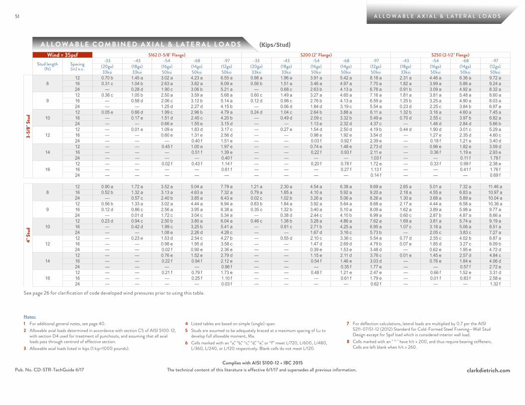
51
clarkdietrich.comPub. No. CD-STR-TechGuide 6/17 The technical content of this literature is effective 6/1/17 and supersedes all previous information.Complies with AISI S100-12 • IBC 2015
51
A L L O W A B L E C O M B I N E D A X I A L & L A T E R A L L O A D S
A L L O W A B L E A X I A L & L A T E R A L L O A D S
(Kips/Stud)
Notes:1 For additional general notes, see page 40.2 Allowable axial loads determined in accordance with section C5 of AISI S100-12,
with section D4 used for treatment of punchouts, and assuming that all axial loads pass through centroid of effective section.
3 Allowable axial loads listed in kips (1 kip=1000 pounds).
4 Listed tables are based on simple (single)-span.5 Studs are assumed to be adequately braced at a maximum spacing of Lu to
develop full allowable moment, Ma.6 Cells marked with an “a,” “b,” “c,” “d,” “e,” or “f” meet L/720, L/600, L/480,
L/360, L/240, or L/120 respectively. Blank cells do not meet L/120.
7 For deflection calculations, lateral loads are multiplied by 0.7 per the AISI S211-07/S1-12 (2012) Standard for Cold-Formed Steel Framing—Wall Stud Design except for 5psf load which is considered interior wall load.
8 Cells marked with an " * " have h/t > 200, and thus require bearing stiffeners. Cells are left blank when h/t > 260.
See page 26 for clarification of code developed wind pressures prior to using this table.
Wind = 35psf S162 (1-5/8" Flange) S200 (2" Flange) S250 (2-1/2" Flange)
Stud length (ft)
Spacing (in) o.c.
-33 -43 -54 -68 -97 -33 -43 -54 -68 -97 -43 -54 -68 -97(20ga) (18ga) (16ga) (14ga) (12ga) (20ga) (18ga) (16ga) (14ga) (12ga) (18ga) (16ga) (14ga) (12ga)33ksi 33ksi 50ksi 50ksi 50ksi 33ksi 33ksi 50ksi 50ksi 50ksi 33ksi 50ksi 50ksi 50ksi
3-5/
8" S
tud
812 0.70 b 1.45 a 3.02 a 4.23 a 6.55 a 0.98 a 1.96 a 3.91 a 5.42 a 8.18 a 2.31 a 4.46 a 6.36 a 9.72 a 16 0.31 c 1.04 b 2.63 a 3.82 a 6.09 a 0.56 b 1.51 a 3.46 a 4.97 a 7.70 a 1.82 a 3.99 a 5.86 a 9.24 a 24 — 0.28 d 1.90 c 3.06 b 5.21 a — 0.68 c 2.63 b 4.13 a 6.78 a 0.91 b 3.09 a 4.92 a 8.32 a
912 0.36 c 1.05 b 2.50 a 3.59 a 5.68 a 0.60 c 1.49 a 3.27 a 4.65 a 7.16 a 1.81 a 3.81 a 5.48 a 8.60 a 16 — 0.58 d 2.06 c 3.12 b 5.14 a 0.12 d 0.98 c 2.76 b 4.13 a 6.59 a 1.25 b 3.25 a 4.90 a 8.03 a 24 — — 1.25 d 2.27 d 4.15 b — 0.06 d 1.84 d 3.19 c 5.54 a 0.23 d 2.25 c 3.84 b 6.97 a
1012 0.05 e 0.66 d 1.99 c 2.96 b 4.79 a 0.24 d 1.04 c 2.64 b 3.88 a 6.11 a 1.32 b 3.16 a 4.60 a 7.45 a 16 — 0.17 e 1.51 d 2.45 c 4.20 b — 0.49 d 2.09 c 3.32 b 5.49 a 0.70 d 2.55 c 3.97 b 6.82 a 24 — — 0.66 e 1.55 e 3.15 d — — 1.13 e 2.32 d 4.37 c — 1.46 d 2.84 d 5.66 b
1212 — 0.01 e 1.09 e 1.83 d 3.17 c — 0.27 e 1.54 d 2.50 d 4.19 b 0.44 d 1.90 d 3.01 c 5.29 a 16 — — 0.60 e 1.31 e 2.56 d — — 0.98 e 1.92 e 3.54 d — 1.27 e 2.35 d 4.60 c 24 — — — 0.40 f 1.51 e — — 0.03 f 0.92 f 2.39 e — 0.18 f 1.21 e 3.40 d
1412 — — 0.45 f 1.00 e 1.97 e — — 0.74 e 1.48 e 2.73 d — 0.96 e 1.82 e 3.59 d 16 — — — 0.51 f 1.39 e — — 0.22 f 0.93 f 2.11 e — 0.36 f 1.19 e 2.93 e 24 — — — — 0.40 f — — — — 1.03 f — — 0.11 f 1.78 f
1612 — — 0.02 f 0.43 f 1.14 f — — 0.20 f 0.78 f 1.72 e — 0.33 f 0.99 f 2.38 e 16 — — — — 0.61 f — — — 0.27 f 1.13 f — — 0.41 f 1.76 f 24 — — — — — — — — — 0.14 f — — — 0.69 f
4" S
tud
812 0.90 a 1.72 a 3.52 a 5.04 a 7.79 a 1.21 a 2.30 a 4.54 a 6.38 a 9.69 a 2.65 a 5.01 a 7.32 a 11.46 a 16 0.52 b 1.32 a 3.13 a 4.63 a 7.32 a 0.79 a 1.85 a 4.10 a 5.92 a 9.20 a 2.18 a 4.55 a 6.83 a 10.97 a 24 — 0.57 c 2.40 b 3.85 a 6.43 a 0.02 c 1.02 b 3.26 a 5.06 a 8.26 a 1.30 a 3.68 a 5.89 a 10.04 a
912 0.56 b 1.33 a 3.02 a 4.44 a 6.94 a 0.83 b 1.84 a 3.92 a 5.64 a 8.68 a 2.17 a 4.44 a 6.58 a 10.36 a 16 0.12 d 0.86 c 2.56 a 3.95 a 6.38 a 0.35 c 1.32 b 3.40 a 5.10 a 8.09 a 1.62 a 3.89 a 5.98 a 9.77 a 24 — 0.01 d 1.72 c 3.04 c 5.34 a — 0.38 d 2.44 c 4.10 b 6.99 a 0.60 c 2.87 b 4.87 a 8.66 a
1012 0.23 d 0.94 c 2.50 b 3.80 a 6.04 a 0.46 c 1.38 b 3.28 a 4.86 a 7.62 a 1.69 a 3.81 a 5.74 a 9.19 a 16 — 0.42 d 1.99 c 3.25 b 5.41 a — 0.81 c 2.71 b 4.25 a 6.95 a 1.07 c 3.18 a 5.06 a 8.51 a 24 — — 1.08 e 2.26 d 4.26 c — — 1.67 d 3.16 c 5.73 b — 2.05 c 3.83 c 7.27 a
1212 — 0.23 e 1.53 d 2.54 c 4.27 b — 0.55 d 2.10 c 3.36 c 5.54 a 0.77 d 2.55 c 4.02 b 6.87 a 16 — — 0.98 e 1.95 d 3.58 c — — 1.47 d 2.69 d 4.79 b 0.07 e 1.85 d 3.27 c 6.09 b 24 — — 0.02 f 0.90 e 2.36 e — — 0.39 e 1.53 e 3.48 d — 0.62 e 1.95 e 4.72 d
1412 — — 0.76 e 1.52 e 2.79 d — — 1.15 e 2.11 d 3.76 c 0.01 e 1.45 e 2.57 d 4.84 c 16 — — 0.22 f 0.94 f 2.12 e — — 0.54 f 1.46 e 3.03 d — 0.76 e 1.84 e 4.06 d 24 — — — — 0.96 f — — — 0.35 f 1.77 e — — 0.57 f 2.72 e
1612 — — 0.21 f 0.79 f 1.73 e — — 0.48 f 1.21 e 2.47 e — 0.66 f 1.52 e 3.31 d 16 — — — 0.25 f 1.10 f — — — 0.61 f 1.79 e — 0.01 f 0.83 f 2.58 e 24 — — — — 0.03 f — — — — 0.62 f — — — 1.32 f

52
clarkdietrich.comPub. No. CD-STR-TechGuide 6/17 The technical content of this literature is effective 6/1/17 and supersedes all previous information.Complies with AISI S100-12 • IBC 2015
52
A L L O W A B L E C O M B I N E D A X I A L & L A T E R A L L O A D S
A L L O W A B L E A X I A L & L A T E R A L L O A D S
(Kips/Stud)
Notes:1 For additional general notes, see page 40.2 Allowable axial loads determined in accordance with section C5 of AISI S100-12,
with section D4 used for treatment of punchouts, and assuming that all axial loads pass through centroid of effective section.
3 Allowable axial loads listed in kips (1 kip=1000 pounds).
4 Listed tables are based on simple (single)-span.5 Studs are assumed to be adequately braced at a maximum spacing of Lu to
develop full allowable moment, Ma.6 Cells marked with an “a,” “b,” “c,” “d,” “e,” or “f” meet L/720, L/600, L/480,
L/360, L/240, or L/120 respectively. Blank cells do not meet L/120.
7 For deflection calculations, lateral loads are multiplied by 0.7 per the AISI S211-07/S1-12 (2012) Standard for Cold-Formed Steel Framing—Wall Stud Design except for 5psf load which is considered interior wall load.
8 Cells marked with an " * " have h/t > 200, and thus require bearing stiffeners. Cells are left blank when h/t > 260.
See page 26 for clarification of code developed wind pressures prior to using this table.
Wind = 35psf S162 (1-5/8" Flange) S200 (2" Flange) S250 (2-1/2" Flange)
Stud length (ft)
Spacing (in) o.c.
-33 -43 -54 -68 -97 -33 -43 -54 -68 -97 -43 -54 -68 -97(20ga) (18ga) (16ga) (14ga) (12ga) (20ga) (18ga) (16ga) (14ga) (12ga) (18ga) (16ga) (14ga) (12ga)33ksi 33ksi 50ksi 50ksi 50ksi 33ksi 33ksi 50ksi 50ksi 50ksi 33ksi 50ksi 50ksi 50ksi
6" S
tud
812 1.60 a 2.65 a 4.90 a 6.76 a 10.73 a 2.01 a 3.41 a 6.56 a 9.13 a 14.81 a 3.74 a 6.78 a 10.12 a 17.34 a 16 1.30 a 2.36 a 4.64 a 6.50 a 10.47 a 1.70 a 3.07 a 6.22 a 8.81 a 14.49 a 3.39 a 6.45 a 9.76 a 16.98 a 24 0.70 a 1.81 a 4.11 a 5.99 a 9.97 a 1.07 a 2.41 a 5.55 a 8.18 a 13.85 a 2.71 a 5.80 a 9.05 a 16.27 a
912 1.34 a 2.40 a 4.66 a 6.52 a 10.49 a 1.73 a 3.09 a 6.17 a 8.72 a 14.30 a 3.41 a 6.40 a 9.64 a 16.71 a 16 0.96 a 2.05 a 4.32 a 6.19 a 10.16 a 1.34 a 2.67 a 5.74 a 8.31 a 13.89 a 2.98 a 5.98 a 9.19 a 16.25 a 24 0.24 a 1.36 a 3.66 a 5.53 a 9.50 a 0.58 a 1.85 a 4.90 a 7.52 a 13.07 a 2.14 a 5.17 a 8.30 a 15.35 a
1012 1.06 a 2.13 a 4.38 a 6.24 a 10.20 a 1.42 a 2.73 a 5.71 a 8.23 a 13.69 a 3.05 a 5.97 a 9.10 a 15.97 a 16 0.61 a 1.70 a 3.96 a 5.82 a 9.78 a 0.95 a 2.23 a 5.19 a 7.73 a 13.18 a 2.52 a 5.47 a 8.55 a 15.40 a 24 — 0.88 a 3.15 a 5.02 a 8.96 a 0.07 b 1.26 a 4.20 a 6.77 a 12.18 a 1.52 a 4.49 a 7.47 a 14.29 a
1212 0.44 b 1.49 a 3.68 a 5.56 a 9.46 a 0.76 a 1.94 a 4.67 a 7.07 a 12.18 a 2.24 a 4.99 a 7.84 a 14.17 a 16 — 0.92 b 3.10 a 4.96 a 8.84 a 0.16 c 1.28 a 3.98 a 6.39 a 11.45 a 1.55 a 4.30 a 7.08 a 13.37 a 24 — — 2.03 c 3.84 b 7.66 a — 0.06 c 2.70 b 5.12 a 10.08 a 0.26 c 3.02 b 5.65 a 11.85 a
1412 — 0.81 c 2.80 b 4.54 a 8.45 a 0.10 c 1.13 b 3.55 a 5.75 a 10.37 a 1.39 a 3.92 a 6.43 a 12.08 a 16 — 0.14 d 2.11 c 3.80 b 7.62 a — 0.36 d 2.74 c 4.93 b 9.46 a 0.56 c 3.09 b 5.50 a 11.08 a 24 — — 0.87 e 2.48 d 6.11 c — — 1.28 d 3.44 d 7.80 b — 1.58 d 3.81 c 9.24 a
1612 — 0.17 d 1.93 d 3.45 c 6.85 a — 0.38 d 2.48 c 4.43 b 8.46 a 0.57 c 2.89 c 5.03 a 9.91 a 16 — — 1.18 e 2.64 d 5.92 c — — 1.60 d 3.53 c 7.44 b — 1.95 d 3.98 c 8.77 a 24 — — — 1.22 e 4.28 d — — 0.08 e 1.94 e 5.64 d — 0.31 e 2.14 d 6.77 c
8" S
tud
812 1.81 a* 2.79 a 4.92 a 6.75 a 10.78 a 2.34 a* 3.82 a 7.10 a 9.70 a 15.42 a 4.21 a 7.53 a 11.12 a 19.10 a 16 1.58 a* 2.58 a 4.73 a 6.56 a 10.59 a 2.10 a* 3.57 a 6.85 a 9.47 a 15.21 a 3.95 a 7.28 a 10.85 a 18.84 a 24 1.14 a* 2.15 a 4.34 a 6.18 a 10.22 a 1.62 a* 3.07 a 6.36 a 9.02 a 14.78 a 3.43 a 6.78 a 10.33 a 18.33 a
912 1.62 a* 2.61 a 4.76 a 6.59 a 10.62 a 2.14 a* 3.61 a 6.89 a 9.50 a 15.23 a 3.98 a 7.28 a 10.85 a 18.79 a 16 1.34 a* 2.34 a 4.51 a 6.35 a 10.38 a 1.83 a* 3.29 a 6.57 a 9.21 a 14.95 a 3.65 a 6.96 a 10.51 a 18.46 a 24 0.78 a* 1.80 a 4.01 a 5.86 a 9.90 a 1.23 a* 2.66 a 5.94 a 8.64 a 14.40 a 3.00 a 6.34 a 9.84 a 17.80 a
1012 1.42 a* 2.41 a 4.57 a 6.40 a 10.43 a 1.91 a* 3.37 a 6.64 a 9.28 a 15.01 a 3.72 a 7.00 a 10.53 a 18.42 a 16 1.07 a* 2.08 a 4.26 a 6.10 a 10.13 a 1.54 a* 2.97 a 6.25 a 8.91 a 14.66 a 3.32 a 6.61 a 10.11 a 18.00 a 24 0.40 a* 1.42 a 3.65 a 5.50 a 9.53 a 0.81 a* 2.20 a 5.47 a 8.20 a 13.96 a 2.52 a 5.83 a 9.28 a 17.18 a
1212 0.95 a* 1.94 a 4.12 a 5.95 a 9.97 a 1.40 a* 2.81 a 6.05 a 8.72 a 14.45 a 3.12 a 6.32 a 9.77 a 17.49 a 16 0.47 a* 1.47 a 3.67 a 5.51 a 9.53 a 0.88 a* 2.26 a 5.48 a 8.19 a 13.93 a 2.55 a 5.76 a 9.16 a 16.88 a 24 — 0.56 a 2.81 a 4.65 a 8.66 a — 1.18 a 4.38 a 7.15 a 12.90 a 1.44 a 4.68 a 7.98 a 15.67 a
1412 0.42 a* 1.40 a 3.58 a 5.40 a 9.39 a 0.81 a* 2.14 a 5.26 a 7.97 a 13.73 a 2.42 a 5.50 a 8.77 a 16.20 a 16 — 0.79 a 2.98 a 4.80 a 8.78 a 0.15 b* 1.42 a 4.51 a 7.25 a 13.00 a 1.68 a 4.77 a 7.96 a 15.36 a 24 — — 1.85 b 3.66 a 7.59 a — 0.08 b 3.10 a 5.88 a 11.58 a 0.29 b 3.38 a 6.42 a 13.75 a
1612 — 0.81 b 2.96 a 4.75 a 8.69 a 0.19 b* 1.41 a 4.30 a 6.91 a 12.50 a 1.66 a 4.58 a 7.59 a 14.53 a 16 — 0.07 c 2.22 b 3.99 a 7.88 a — 0.55 b 3.40 a 6.02 a 11.56 a 0.78 b 3.69 a 6.59 a 13.48 a 24 — — 0.84 d 2.57 c 6.36 a — — 1.75 c 4.37 b 9.79 a — 2.04 c 4.75 a 11.51 a
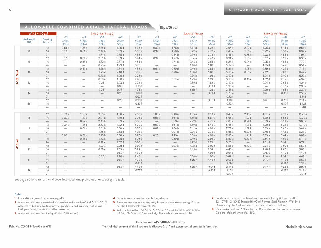
53
clarkdietrich.comPub. No. CD-STR-TechGuide 6/17 The technical content of this literature is effective 6/1/17 and supersedes all previous information.Complies with AISI S100-12 • IBC 2015
53
A L L O W A B L E C O M B I N E D A X I A L & L A T E R A L L O A D S
A L L O W A B L E A X I A L & L A T E R A L L O A D S
(Kips/Stud)
Notes:1 For additional general notes, see page 40.2 Allowable axial loads determined in accordance with section C5 of AISI S100-12,
with section D4 used for treatment of punchouts, and assuming that all axial loads pass through centroid of effective section.
3 Allowable axial loads listed in kips (1 kip=1000 pounds).
4 Listed tables are based on simple (single)-span.5 Studs are assumed to be adequately braced at a maximum spacing of Lu to
develop full allowable moment, Ma.6 Cells marked with an “a,” “b,” “c,” “d,” “e,” or “f” meet L/720, L/600, L/480,
L/360, L/240, or L/120 respectively. Blank cells do not meet L/120.
7 For deflection calculations, lateral loads are multiplied by 0.7 per the AISI S211-07/S1-12 (2012) Standard for Cold-Formed Steel Framing—Wall Stud Design except for 5psf load which is considered interior wall load.
8 Cells marked with an " * " have h/t > 200, and thus require bearing stiffeners. Cells are left blank when h/t > 260.
See page 26 for clarification of code developed wind pressures prior to using this table.
Wind = 40psf S162 (1-5/8" Flange) S200 (2" Flange) S250 (2-1/2" Flange)
Stud length (ft)
Spacing (in) o.c.
-33 -43 -54 -68 -97 -33 -43 -54 -68 -97 -43 -54 -68 -97(20ga) (18ga) (16ga) (14ga) (12ga) (20ga) (18ga) (16ga) (14ga) (12ga) (18ga) (16ga) (14ga) (12ga)33ksi 33ksi 50ksi 50ksi 50ksi 33ksi 33ksi 50ksi 50ksi 50ksi 33ksi 50ksi 50ksi 50ksi
3-5/
8" S
tud
812 0.53 b 1.27 a 2.85 a 4.05 a 6.35 a 0.80 b 1.76 a 3.71 a 5.22 a 7.97 a 2.09 a 4.26 a 6.14 a 9.51 a 16 0.10 d 0.81 c 2.42 b 3.59 a 5.83 a 0.32 c 1.26 b 3.22 a 4.72 a 7.43 a 1.55 a 3.72 a 5.58 a 8.97 a 24 — — 1.61 d 2.75 c 4.85 a — 0.34 d 2.30 c 3.79 b 6.41 a 0.55 c 2.73 b 4.54 a 7.95 a
912 0.17 d 0.84 c 2.31 b 3.39 a 5.44 a 0.39 c 1.27 b 3.04 a 4.42 a 6.91 a 1.56 a 3.57 a 5.22 a 8.35 a 16 — 0.33 d 1.82 c 2.87 b 4.84 a — 0.71 c 2.48 c 3.85 a 6.28 a 0.94 c 2.95 b 4.58 a 7.72 a 24 — — 0.93 e 1.93 d 3.75 c — — 1.48 d 2.82 c 5.12 b — 1.85 d 3.42 c 6.54 a
1012 — 0.44 d 1.78 c 2.74 b 4.53 a 0.01 d 0.80 d 2.40 c 3.63 b 5.84 a 1.05 c 2.89 b 4.32 a 7.17 a 16 — — 1.26 d 2.18 d 3.89 b — 0.20 e 1.80 d 3.02 c 5.15 a 0.38 d 2.22 c 3.63 b 6.47 a 24 — — 0.33 e 1.20 e 2.73 d — — 0.76 e 1.93 e 3.92 c — 1.04 e 2.40 d 5.20 c
1212 — — 0.88 e 1.60 e 2.90 d — 0.01 e 1.29 e 2.24 d 3.90 c 0.15 e 1.62 d 2.72 c 4.99 b 16 — — 0.35 f 1.03 e 2.24 e — — 0.69 e 1.62 e 3.19 d — 0.94 e 2.01 d 4.24 c 24 — — — 0.06 f 1.10 f — — — 0.54 f 1.95 e — — 0.77 e 2.93 e
1412 — — 0.24 f 0.78 f 1.71 e — — 0.51 f 1.23 e 2.45 e — 0.70 e 1.54 e 3.30 d 16 — — — 0.25 f 1.09 f — — — 0.64 f 1.78 e — 0.05 f 0.86 f 2.58 e 24 — — — — 0.02 f — — — — 0.62 f — — — 1.34 f
1612 — — — 0.23 f 0.90 f — — — 0.55 f 1.46 f — 0.08 f 0.73 f 2.11 e 16 — — — — 0.33 f — — — — 0.83 f — — 0.10 f 1.43 f 24 — — — — — — — — — — — — — 0.28 f
4" S
tud
812 0.73 a 1.55 a 3.35 a 4.86 a 7.58 a 1.03 a 2.10 a 4.35 a 6.18 a 9.48 a 2.45 a 4.81 a 7.11 a 11.25 a 16 0.30 c 1.10 a 2.91 a 4.40 a 7.06 a 0.57 b 1.61 a 3.85 a 5.67 a 8.93 a 1.92 a 4.30 a 6.55 a 10.70 a 24 — 0.27 c 2.10 b 3.53 a 6.06 a — 0.69 c 2.92 b 4.71 a 7.88 a 0.94 b 3.33 a 5.51 a 9.65 a
912 0.37 c 1.13 b 2.82 a 4.22 a 6.70 a 0.62 b 1.61 a 3.69 a 5.40 a 8.43 a 1.93 a 4.20 a 6.32 a 10.10 a 16 — 0.61 c 2.31 b 3.68 a 6.07 a 0.09 d 1.04 b 3.11 a 4.80 a 7.77 a 1.32 b 3.59 a 5.65 a 9.44 a 24 — — 1.38 d 2.68 c 4.92 b — 0.01 d 2.06 c 3.70 b 6.55 a 0.20 d 2.46 c 4.42 b 8.21 a
1012 0.02 d 0.71 c 2.28 b 3.56 a 5.76 a 0.23 d 1.13 c 3.03 a 4.60 a 7.33 a 1.41 b 3.53 a 5.44 a 8.89 a 16 — 0.15 d 1.72 d 2.95 c 5.06 a — 0.50 d 2.40 c 3.93 b 6.59 a 0.73 c 2.84 b 4.69 a 8.14 a 24 — — 0.72 e 1.87 d 3.80 c — — 1.27 d 2.73 d 5.25 b — 1.61 d 3.34 c 6.77 b
1212 — — 1.29 e 2.28 d 3.96 c — 0.27 e 1.82 d 3.06 c 5.21 b 0.46 d 2.24 c 3.69 b 6.53 a 16 — — 0.69 e 1.63 e 3.21 d — — 1.15 e 2.34 d 4.40 c — 1.48 d 2.87 d 5.68 b 24 — — — 0.50 f 1.89 e — — — 1.09 e 2.97 e — 0.15 e 1.45 e 4.19 d
1412 — — 0.52 f 1.26 e 2.49 d — — 0.88 e 1.82 e 3.44 d — 1.14 e 2.24 d 4.49 c 16 — — — 0.63 f 1.76 e — — 0.23 f 1.12 e 2.65 e — 0.40 f 1.45 e 3.66 d 24 — — — — 0.51 f — — — — 1.29 f — — 0.09 f 2.21 e
1612 — — — 0.55 f 1.45 e — — 0.23 f 0.94 f 2.17 e — 0.37 f 1.21 e 2.98 e 16 — — — — 0.77 f — — — 0.30 f 1.43 f — — 0.47 f 2.19 e 24 — — — — — — — — — 0.17 f — — — 0.84 f
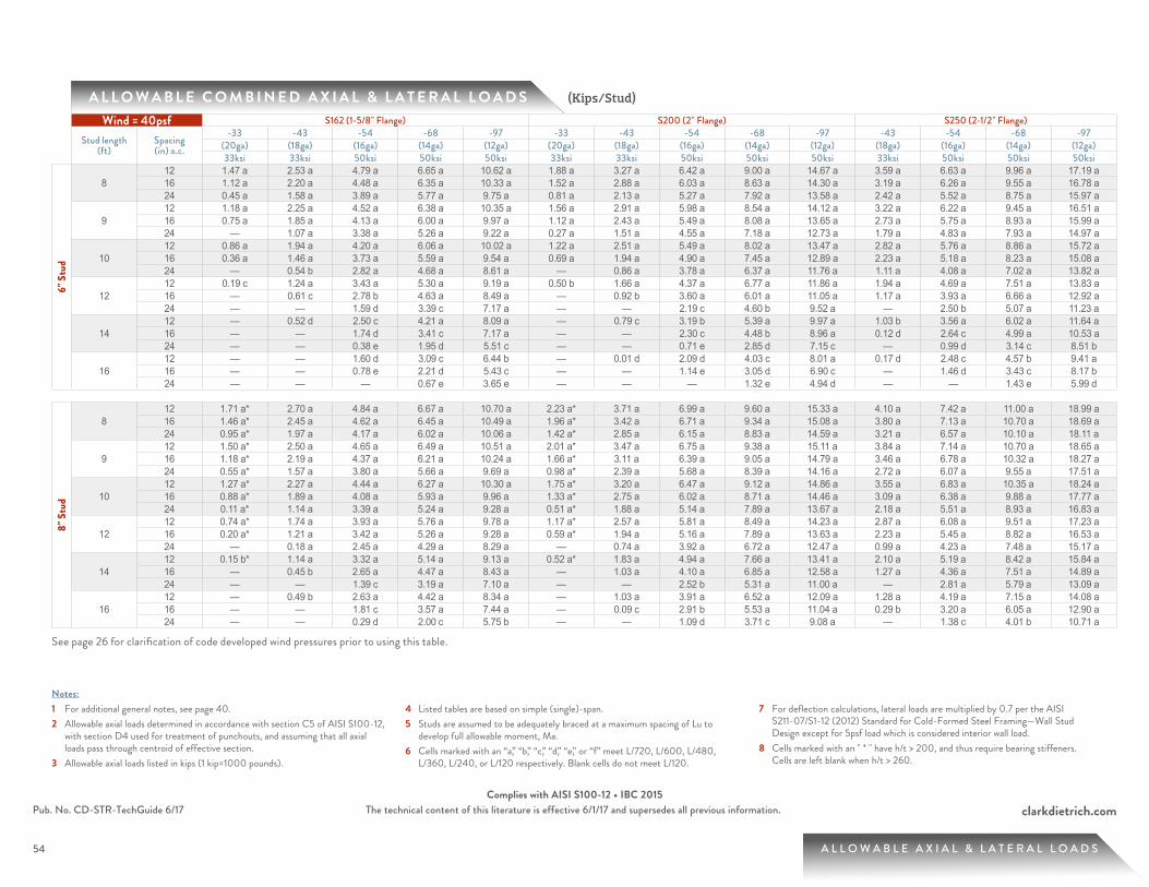
54
clarkdietrich.comPub. No. CD-STR-TechGuide 6/17 The technical content of this literature is effective 6/1/17 and supersedes all previous information.Complies with AISI S100-12 • IBC 2015
54
A L L O W A B L E C O M B I N E D A X I A L & L A T E R A L L O A D S
A L L O W A B L E A X I A L & L A T E R A L L O A D S
(Kips/Stud)
Notes:1 For additional general notes, see page 40.2 Allowable axial loads determined in accordance with section C5 of AISI S100-12,
with section D4 used for treatment of punchouts, and assuming that all axial loads pass through centroid of effective section.
3 Allowable axial loads listed in kips (1 kip=1000 pounds).
4 Listed tables are based on simple (single)-span.5 Studs are assumed to be adequately braced at a maximum spacing of Lu to
develop full allowable moment, Ma.6 Cells marked with an “a,” “b,” “c,” “d,” “e,” or “f” meet L/720, L/600, L/480,
L/360, L/240, or L/120 respectively. Blank cells do not meet L/120.
7 For deflection calculations, lateral loads are multiplied by 0.7 per the AISI S211-07/S1-12 (2012) Standard for Cold-Formed Steel Framing—Wall Stud Design except for 5psf load which is considered interior wall load.
8 Cells marked with an " * " have h/t > 200, and thus require bearing stiffeners. Cells are left blank when h/t > 260.
See page 26 for clarification of code developed wind pressures prior to using this table.
Wind = 40psf S162 (1-5/8" Flange) S200 (2" Flange) S250 (2-1/2" Flange)
Stud length (ft)
Spacing (in) o.c.
-33 -43 -54 -68 -97 -33 -43 -54 -68 -97 -43 -54 -68 -97(20ga) (18ga) (16ga) (14ga) (12ga) (20ga) (18ga) (16ga) (14ga) (12ga) (18ga) (16ga) (14ga) (12ga)33ksi 33ksi 50ksi 50ksi 50ksi 33ksi 33ksi 50ksi 50ksi 50ksi 33ksi 50ksi 50ksi 50ksi
6" S
tud
812 1.47 a 2.53 a 4.79 a 6.65 a 10.62 a 1.88 a 3.27 a 6.42 a 9.00 a 14.67 a 3.59 a 6.63 a 9.96 a 17.19 a 16 1.12 a 2.20 a 4.48 a 6.35 a 10.33 a 1.52 a 2.88 a 6.03 a 8.63 a 14.30 a 3.19 a 6.26 a 9.55 a 16.78 a 24 0.45 a 1.58 a 3.89 a 5.77 a 9.75 a 0.81 a 2.13 a 5.27 a 7.92 a 13.58 a 2.42 a 5.52 a 8.75 a 15.97 a
912 1.18 a 2.25 a 4.52 a 6.38 a 10.35 a 1.56 a 2.91 a 5.98 a 8.54 a 14.12 a 3.22 a 6.22 a 9.45 a 16.51 a 16 0.75 a 1.85 a 4.13 a 6.00 a 9.97 a 1.12 a 2.43 a 5.49 a 8.08 a 13.65 a 2.73 a 5.75 a 8.93 a 15.99 a 24 — 1.07 a 3.38 a 5.26 a 9.22 a 0.27 a 1.51 a 4.55 a 7.18 a 12.73 a 1.79 a 4.83 a 7.93 a 14.97 a
1012 0.86 a 1.94 a 4.20 a 6.06 a 10.02 a 1.22 a 2.51 a 5.49 a 8.02 a 13.47 a 2.82 a 5.76 a 8.86 a 15.72 a 16 0.36 a 1.46 a 3.73 a 5.59 a 9.54 a 0.69 a 1.94 a 4.90 a 7.45 a 12.89 a 2.23 a 5.18 a 8.23 a 15.08 a 24 — 0.54 b 2.82 a 4.68 a 8.61 a — 0.86 a 3.78 a 6.37 a 11.76 a 1.11 a 4.08 a 7.02 a 13.82 a
1212 0.19 c 1.24 a 3.43 a 5.30 a 9.19 a 0.50 b 1.66 a 4.37 a 6.77 a 11.86 a 1.94 a 4.69 a 7.51 a 13.83 a 16 — 0.61 c 2.78 b 4.63 a 8.49 a — 0.92 b 3.60 a 6.01 a 11.05 a 1.17 a 3.93 a 6.66 a 12.92 a 24 — — 1.59 d 3.39 c 7.17 a — — 2.19 c 4.60 b 9.52 a — 2.50 b 5.07 a 11.23 a
1412 — 0.52 d 2.50 c 4.21 a 8.09 a — 0.79 c 3.19 b 5.39 a 9.97 a 1.03 b 3.56 a 6.02 a 11.64 a 16 — — 1.74 d 3.41 c 7.17 a — — 2.30 c 4.48 b 8.96 a 0.12 d 2.64 c 4.99 a 10.53 a 24 — — 0.38 e 1.95 d 5.51 c — — 0.71 e 2.85 d 7.15 c — 0.99 d 3.14 c 8.51 b
1612 — — 1.60 d 3.09 c 6.44 b — 0.01 d 2.09 d 4.03 c 8.01 a 0.17 d 2.48 c 4.57 b 9.41 a 16 — — 0.78 e 2.21 d 5.43 c — — 1.14 e 3.05 d 6.90 c — 1.46 d 3.43 c 8.17 b 24 — — — 0.67 e 3.65 e — — — 1.32 e 4.94 d — — 1.43 e 5.99 d
8" S
tud
812 1.71 a* 2.70 a 4.84 a 6.67 a 10.70 a 2.23 a* 3.71 a 6.99 a 9.60 a 15.33 a 4.10 a 7.42 a 11.00 a 18.99 a 16 1.46 a* 2.45 a 4.62 a 6.45 a 10.49 a 1.96 a* 3.42 a 6.71 a 9.34 a 15.08 a 3.80 a 7.13 a 10.70 a 18.69 a 24 0.95 a* 1.97 a 4.17 a 6.02 a 10.06 a 1.42 a* 2.85 a 6.15 a 8.83 a 14.59 a 3.21 a 6.57 a 10.10 a 18.11 a
912 1.50 a* 2.50 a 4.65 a 6.49 a 10.51 a 2.01 a* 3.47 a 6.75 a 9.38 a 15.11 a 3.84 a 7.14 a 10.70 a 18.65 a 16 1.18 a* 2.19 a 4.37 a 6.21 a 10.24 a 1.66 a* 3.11 a 6.39 a 9.05 a 14.79 a 3.46 a 6.78 a 10.32 a 18.27 a 24 0.55 a* 1.57 a 3.80 a 5.66 a 9.69 a 0.98 a* 2.39 a 5.68 a 8.39 a 14.16 a 2.72 a 6.07 a 9.55 a 17.51 a
1012 1.27 a* 2.27 a 4.44 a 6.27 a 10.30 a 1.75 a* 3.20 a 6.47 a 9.12 a 14.86 a 3.55 a 6.83 a 10.35 a 18.24 a 16 0.88 a* 1.89 a 4.08 a 5.93 a 9.96 a 1.33 a* 2.75 a 6.02 a 8.71 a 14.46 a 3.09 a 6.38 a 9.88 a 17.77 a 24 0.11 a* 1.14 a 3.39 a 5.24 a 9.28 a 0.51 a* 1.88 a 5.14 a 7.89 a 13.67 a 2.18 a 5.51 a 8.93 a 16.83 a
1212 0.74 a* 1.74 a 3.93 a 5.76 a 9.78 a 1.17 a* 2.57 a 5.81 a 8.49 a 14.23 a 2.87 a 6.08 a 9.51 a 17.23 a 16 0.20 a* 1.21 a 3.42 a 5.26 a 9.28 a 0.59 a* 1.94 a 5.16 a 7.89 a 13.63 a 2.23 a 5.45 a 8.82 a 16.53 a 24 — 0.18 a 2.45 a 4.29 a 8.29 a — 0.74 a 3.92 a 6.72 a 12.47 a 0.99 a 4.23 a 7.48 a 15.17 a
1412 0.15 b* 1.14 a 3.32 a 5.14 a 9.13 a 0.52 a* 1.83 a 4.94 a 7.66 a 13.41 a 2.10 a 5.19 a 8.42 a 15.84 a 16 — 0.45 b 2.65 a 4.47 a 8.43 a — 1.03 a 4.10 a 6.85 a 12.58 a 1.27 a 4.36 a 7.51 a 14.89 a 24 — — 1.39 c 3.19 a 7.10 a — — 2.52 b 5.31 a 11.00 a — 2.81 a 5.79 a 13.09 a
1612 — 0.49 b 2.63 a 4.42 a 8.34 a — 1.03 a 3.91 a 6.52 a 12.09 a 1.28 a 4.19 a 7.15 a 14.08 a 16 — — 1.81 c 3.57 a 7.44 a — 0.09 c 2.91 b 5.53 a 11.04 a 0.29 b 3.20 a 6.05 a 12.90 a 24 — — 0.29 d 2.00 c 5.75 b — — 1.09 d 3.71 c 9.08 a — 1.38 c 4.01 b 10.71 a
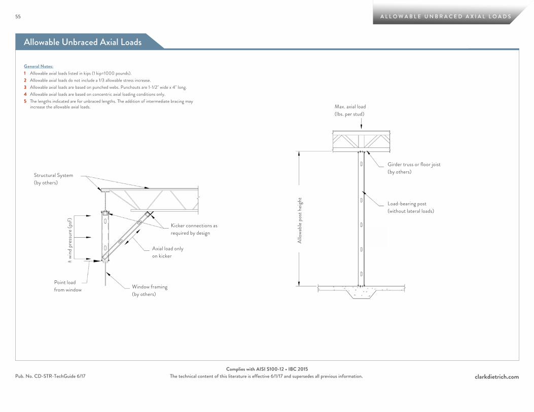
Allowable Unbraced Axial Loads
55
clarkdietrich.comPub. No. CD-STR-TechGuide 6/17 The technical content of this literature is effective 6/1/17 and supersedes all previous information.Complies with AISI S100-12 • IBC 2015
55 A L L O W A B L E U N B R A C E D A X I A L L O A D S
General Notes:1 Allowable axial loads listed in kips (1 kip=1000 pounds).2 Allowable axial loads do not include a 1/3 allowable stress increase.3 Allowable axial loads are based on punched webs. Punchouts are 1-1/2" wide x 4" long.4 Allowable axial loads are based on concentric axial loading conditions only.5 The lengths indicated are for unbraced lengths. The addition of intermediate bracing may
increase the allowable axial loads.
Kicker connections as required by design
Axial load only on kicker
± wi
nd p
ress
ure (
psf)
Structural System (by others)
Point load from window Window framing
(by others)Al
lowa
ble p
ost h
eight
Max. axial load (lbs. per stud)
Girder truss or floor joist (by others)
Load-bearing post (without lateral loads)

56
clarkdietrich.comPub. No. CD-STR-TechGuide 6/17 The technical content of this literature is effective 6/1/17 and supersedes all previous information.Complies with AISI S100-12 • IBC 2015
56 A L L O W A B L E U N B R A C E D A X I A L L O A D S
A L L O W A B L E U N B R A C E D A X I A L L O A D S Based on length (Kips)
Notes:1 Listed axial loads marked with " * " indicate the KL/r > 300.2 Listed axial loads marked with "ws" indicate that h/t > 200. This indicates that web stiffeners are required to prevent web
crippling at points of concentrated loads.3 Listed capacities are calculated per AISI-NASPEC S100-12.
Member Fy (ksi) Unbraced Length (ft)1 1.5 2 2.5 3 3.5 4 5 6 7 8 9 10 11 12 13 14 15 16 17 18 19 20
3-5/
8" S
tud
362S137-33 33 2.66 2.59 2.49 2.38 2.21 2.02 1.82 1.44 1.09 0.86 0.70 0.56 0.46 0.38 0.32 0.27 * 0.23 * 0.20 * 0.18 * 0.16 * 0.14 * 0.13 * 0.11 * 362S137-43 33 3.81 3.67 3.49 3.27 3.03 2.78 2.52 2.02 1.57 1.18 0.90 0.71 0.58 0.48 0.40 0.34 * 0.30 * 0.26 * 0.23 * 0.20 * 0.18 * 0.16 * 0.14 * 362S137-54 50 6.88 6.62 6.22 5.66 5.06 4.46 3.89 2.79 1.93 1.42 1.09 0.86 0.70 0.58 0.48 0.41 * 0.36 * 0.31 * 0.27 * 0.24 * 0.21 * 0.19 * 0.17 * 362S137-68 50 9.28 8.78 8.14 7.43 6.67 5.83 4.93 3.31 2.30 1.69 1.29 1.02 0.83 0.68 0.57 0.49 * 0.42 * 0.37 * 0.32 * 0.29 * 0.26 * 0.23 * 0.21 * 362S137-97 50 13.07 12.32 11.32 10.14 8.87 7.57 6.31 4.15 2.88 2.12 1.62 1.28 1.04 0.86 0.72 * 0.61 * 0.53 * 0.46 * 0.40 * 0.36 * 0.32 * 0.29 * 0.26 * 362S162-33 33 3.12 3.05 2.96 2.84 2.69 2.50 2.29 1.87 1.47 1.14 0.91 0.75 0.63 0.53 0.46 0.41 0.37 0.33 0.30 * 0.27 * 0.24 * 0.22 * 0.20 * 362S162-43 33 4.43 4.30 4.12 3.91 3.67 3.40 3.13 2.58 2.06 1.60 1.28 1.05 0.89 0.77 0.68 0.59 0.51 0.44 0.39 * 0.35 * 0.31 * 0.28 * 0.25 * 362S162-54 50 7.99 7.74 7.44 6.87 6.24 5.60 4.96 3.76 2.75 2.13 1.73 1.45 1.21 1.00 0.84 0.72 0.62 0.54 0.47 * 0.42 * 0.37 * 0.34 * 0.30 * 362S162-68 50 10.79 10.31 9.68 8.95 8.16 7.31 6.46 4.92 3.70 2.94 2.28 1.80 1.46 1.20 1.01 0.86 0.74 0.65 * 0.57 * 0.50 * 0.45 * 0.40 * 0.36 * 362S162-97 50 15.24 14.50 13.58 12.55 11.48 10.43 9.43 7.30 5.21 3.83 2.93 2.32 1.88 1.55 1.30 1.11 0.96 0.83 * 0.73 * 0.65 * 0.58 * 0.52 * 0.47 * 362S200-33 33 3.41 3.35 3.26 3.15 3.02 2.88 2.72 2.35 1.96 1.53 1.21 0.99 0.82 0.69 0.59 0.52 0.46 0.41 0.37 0.33 0.30 0.28 0.26 * 362S200-43 33 5.12 5.03 4.88 4.70 4.47 4.20 3.90 3.28 2.68 2.12 1.66 1.35 1.13 0.96 0.83 0.73 0.66 0.59 0.54 0.50 0.46 0.43 0.40 * 362S200-54 50 8.79 8.62 8.41 8.12 7.70 7.02 6.30 4.90 3.62 2.75 2.18 1.79 1.51 1.31 1.15 1.03 0.93 0.85 0.78 0.72 0.68 0.62 0.56 * 362S200-68 50 12.43 12.11 11.64 10.87 10.02 9.12 8.15 6.30 4.72 3.64 2.94 2.46 2.11 1.85 1.65 1.50 1.37 1.21 1.06 0.94 0.84 0.75 * 0.68 * 362S200-97 50 18.07 17.33 16.37 15.26 14.06 12.82 11.61 9.35 7.44 5.96 4.98 4.30 3.58 2.96 2.49 2.12 1.83 1.59 1.40 1.24 1.11 0.99 * 0.90 * 362S250-43 33 5.25 5.16 5.04 4.89 4.71 4.51 4.29 3.80 3.15 2.49 1.95 1.57 1.30 1.09 0.94 0.82 0.73 0.65 0.59 0.53 0.49 0.45 0.42362S250-54 50 9.00 8.77 8.46 8.08 7.63 7.13 6.64 5.67 4.25 3.20 2.51 2.04 1.70 1.45 1.26 1.11 0.99 0.90 0.82 0.75 0.70 0.65 0.61362S250-68 50 12.44 12.16 11.78 11.32 10.80 10.00 9.13 7.36 5.46 4.15 3.30 2.72 2.30 1.99 1.75 1.57 1.42 1.30 1.19 1.11 1.04 0.98 0.92362S250-97 50 19.64 18.98 18.14 17.19 16.24 14.88 13.43 10.69 8.30 6.50 5.32 4.50 3.91 3.47 3.12 2.84 2.62 2.43 2.27 2.13 1.96 1.76 1.59
4" S
tud
400S137-33 33 2.69 2.62 2.53 2.42 2.27 2.09 1.90 1.52 1.18 0.91 0.72 0.58 0.48 0.39 0.33 0.28 * 0.24 * 0.21 * 0.19 * 0.17 * 0.15 * 0.13 * 0.12 * 400S137-43 33 3.86 3.73 3.56 3.36 3.13 2.88 2.63 2.13 1.62 1.23 0.95 0.75 0.61 0.50 0.42 0.36 * 0.31 * 0.27 * 0.24 * 0.21 * 0.19 * 0.17 * 0.15 * 400S137-54 50 6.99 6.74 6.39 5.85 5.28 4.68 4.04 2.85 2.03 1.49 1.14 0.90 0.73 0.60 0.51 0.43 * 0.37 * 0.32 * 0.28 * 0.25 * 0.23 * 0.20 * 0.18 * 400S137-68 50 9.51 9.04 8.44 7.70 6.89 6.04 5.18 3.47 2.41 1.77 1.35 1.07 0.87 0.72 0.60 * 0.51 * 0.44 * 0.39 * 0.34 * 0.30 * 0.27 * 0.24 * 0.22 * 400S137-97 50 14.09 13.24 12.13 10.84 9.45 8.03 6.66 4.35 3.02 2.22 1.70 1.34 1.09 0.90 0.76 * 0.64 * 0.56 * 0.48 * 0.42 * 0.38 * 0.34 * 0.30 * 0.27 * 400S162-33 33 3.15 3.08 3.00 2.89 2.75 2.58 2.39 1.99 1.60 1.25 1.01 0.83 0.70 0.61 0.53 0.46 0.41 0.36 0.32 * 0.28 * 0.25 * 0.23 * 0.21 * 400S162-43 33 4.49 4.37 4.20 4.01 3.78 3.54 3.28 2.75 2.24 1.78 1.45 1.20 1.01 0.86 0.73 0.62 0.53 0.47 0.41 * 0.36 * 0.32 * 0.29 * 0.26 * 400S162-54 50 8.10 7.88 7.59 7.10 6.51 5.90 5.28 4.10 3.10 2.43 1.96 1.57 1.27 1.05 0.88 0.75 0.65 0.56 * 0.50 * 0.44 * 0.39 * 0.35 * 0.32 * 400S162-68 50 11.03 10.58 10.00 9.32 8.58 7.80 7.03 5.56 4.21 3.11 2.38 1.88 1.53 1.26 1.06 0.90 0.78 0.68 * 0.60 * 0.53 * 0.47 * 0.42 * 0.38 * 400S162-97 50 16.31 15.59 14.68 13.64 12.55 11.45 10.21 7.69 5.47 4.02 3.07 2.43 1.97 1.63 1.37 1.16 1.00 0.87 * 0.77 * 0.68 * 0.61 * 0.55 * 0.49 * 400S200-33 33 3.44 3.38 3.30 3.20 3.09 2.96 2.81 2.48 2.12 1.71 1.36 1.11 0.93 0.80 0.69 0.60 0.53 0.47 0.42 0.38 0.35 0.32 0.30 * 400S200-43 33 5.17 5.09 4.96 4.80 4.60 4.35 4.08 3.50 2.92 2.38 1.91 1.57 1.31 1.11 0.96 0.84 0.75 0.68 0.62 0.56 0.52 0.48 0.45 * 400S200-54 50 8.89 8.75 8.55 8.32 7.93 7.40 6.72 5.37 4.13 3.20 2.53 2.07 1.75 1.50 1.32 1.17 1.06 0.96 0.88 0.81 0.72 0.65 * 0.59 * 400S200-68 50 12.66 12.37 12.00 11.30 10.52 9.68 8.82 7.12 5.50 4.22 3.39 2.83 2.42 2.11 1.88 1.69 1.45 1.27 1.11 0.99 0.88 0.79 * 0.71 * 400S200-97 50 19.17 18.46 17.55 16.47 15.29 14.07 12.84 10.51 8.49 6.83 5.68 4.63 3.75 3.10 2.61 2.22 1.91 1.67 1.47 1.30 1.16 1.04 * 0.94 * 400S250-43 33 5.30 5.22 5.12 4.99 4.83 4.66 4.46 4.01 3.47 2.84 2.27 1.85 1.54 1.29 1.11 0.97 0.85 0.76 0.69 0.62 0.57 0.53 0.49400S250-54 50 9.12 8.92 8.65 8.31 7.91 7.47 6.98 6.15 4.94 3.78 2.98 2.41 2.01 1.71 1.48 1.30 1.16 1.04 0.95 0.87 0.80 0.75 0.70400S250-68 50 12.67 12.42 12.09 11.69 11.22 10.59 9.82 8.37 6.49 4.92 3.90 3.20 2.69 2.32 2.03 1.81 1.63 1.49 1.37 1.27 1.19 1.11 1.05400S250-97 50 20.74 20.13 19.33 18.41 17.45 16.34 14.92 12.15 9.68 7.61 6.20 5.22 4.51 3.98 3.58 3.25 2.99 2.77 2.59 2.30 2.05 1.84 1.66
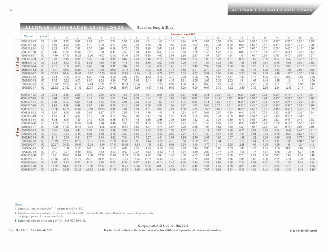
57
clarkdietrich.comPub. No. CD-STR-TechGuide 6/17 The technical content of this literature is effective 6/1/17 and supersedes all previous information.Complies with AISI S100-12 • IBC 2015
57 A L L O W A B L E U N B R A C E D A X I A L L O A D S
A L L O W A B L E U N B R A C E D A X I A L L O A D S Based on length (Kips)
Notes:1 Listed axial loads marked with " * " indicate the KL/r > 300.2 Listed axial loads marked with "ws" indicate that h/t > 200. This indicates that web stiffeners are required to prevent web
crippling at points of concentrated loads.3 Listed capacities are calculated per AISI-NASPEC S100-12.
Member Fy (ksi) Unbraced Length (ft)1 1.5 2 2.5 3 3.5 4 5 6 7 8 9 10 11 12 13 14 15 16 17 18 19 20
5-1/
2" S
tud
550S162-33 33 3.20 3.15 3.07 2.99 2.87 2.74 2.57 2.20 1.81 1.45 1.15 0.94 0.78 0.67 0.58 0.50 0.44 0.39 * 0.35 * 0.32 * 0.29 * 0.26 * 0.23 * 550S162-43 33 4.60 4.50 4.36 4.19 3.99 3.77 3.53 3.02 2.50 1.99 1.59 1.30 1.09 0.92 0.80 0.69 0.61 0.53 * 0.47 * 0.41 * 0.37 * 0.33 * 0.30 * 550S162-54 50 8.32 8.13 7.87 7.50 6.96 6.38 5.76 4.53 3.39 2.61 2.08 1.70 1.42 1.20 1.01 0.86 0.74 0.65 * 0.57 * 0.50 * 0.45 * 0.40 * 0.36 * 550S162-68 50 11.47 11.08 10.56 9.92 9.20 8.41 7.59 5.93 4.43 3.40 2.70 2.16 1.75 1.45 1.22 1.04 0.89 0.78 * 0.68 * 0.61 * 0.54 * 0.49 * 0.44 * 550S162-97 50 17.79 17.15 16.29 15.26 14.07 12.80 11.46 8.78 6.30 4.63 3.54 2.80 2.27 1.87 1.57 1.34 1.16 * 1.01 * 0.89 * 0.78 * 0.70 * 0.63 * 0.57 * 550S200-33 33 3.49 3.45 3.39 3.32 3.23 3.13 3.02 2.76 2.46 2.15 1.80 1.48 1.24 1.06 0.92 0.81 0.72 0.65 0.59 0.54 0.49 0.45 * 0.41 * 550S200-43 33 5.28 5.22 5.13 5.01 4.86 4.69 4.48 4.00 3.50 3.00 2.53 2.09 1.77 1.52 1.33 1.18 1.05 0.94 0.84 0.75 0.68 0.61 * 0.55 * 550S200-54 50 9.11 9.00 8.85 8.67 8.46 8.12 7.67 6.50 5.34 4.27 3.45 2.87 2.45 2.09 1.80 1.56 1.37 1.20 1.05 0.93 0.83 0.75 * 0.67 * 550S200-68 50 13.11 12.90 12.62 12.20 11.58 10.90 10.18 8.68 7.22 5.87 4.74 3.86 3.21 2.70 2.27 1.94 1.67 1.45 1.28 1.13 1.01 0.91 * 0.82 * 550S200-97 50 20.73 20.24 19.57 18.77 17.85 16.86 15.82 13.54 11.12 8.78 6.75 5.33 4.32 3.57 3.00 2.56 2.20 1.92 1.69 1.49 1.33 * 1.20 * 1.08 * 550S250-43 33 5.41 5.36 5.29 5.20 5.09 4.96 4.82 4.50 4.14 3.72 3.19 2.69 2.25 1.92 1.67 1.47 1.30 1.17 1.06 0.97 0.89 0.82 0.76550S250-54 50 9.36 9.22 9.03 8.80 8.52 8.20 7.85 7.06 6.41 5.46 4.39 3.61 3.05 2.62 2.29 2.02 1.81 1.63 1.49 1.35 1.24 1.14 1.06550S250-68 50 13.13 12.96 12.73 12.44 12.11 11.73 11.31 10.04 8.87 7.35 5.97 4.96 4.21 3.65 3.21 2.84 2.53 2.28 2.08 1.91 1.76 1.58 1.43550S250-97 50 22.32 21.92 21.39 20.75 20.04 19.28 18.54 16.26 13.97 11.82 9.86 8.20 6.98 6.07 5.30 4.52 3.89 3.39 2.98 2.64 2.36 2.11 1.91
6" S
tud
600S137-33 33 2.73 2.66 2.56 2.45 2.29 2.09 1.89 1.48 1.11 0.86 0.69 0.57 0.48 0.41 0.35 * 0.31 * 0.27 * 0.24 * 0.22 * 0.20 * 0.17 * 0.16 * 0.14 * 600S137-43 33 3.96 3.83 3.65 3.43 3.18 2.91 2.62 2.05 1.54 1.20 0.96 0.79 0.67 0.57 0.49 * 0.42 * 0.37 * 0.32 * 0.28 * 0.25 * 0.22 * 0.20 * 0.18 * 600S137-54 50 7.20 6.93 6.51 5.91 5.26 4.58 3.91 2.75 2.03 1.58 1.27 1.04 0.86 0.71 0.60 * 0.51 * 0.44 * 0.38 * 0.34 * 0.30 * 0.27 * 0.24 * 0.22 * 600S137-68 50 9.92 9.39 8.69 7.87 6.98 6.06 5.15 3.60 2.66 2.06 1.61 1.27 1.03 0.85 0.71 * 0.61 * 0.53 * 0.46 * 0.40 * 0.36 * 0.32 * 0.29 * 0.26 * 600S137-97 50 15.65 14.74 13.56 12.19 10.69 9.15 7.64 5.19 3.61 2.65 2.03 1.60 1.30 1.07 * 0.90 * 0.77 * 0.66 * 0.58 * 0.51 * 0.45 * 0.40 * 0.36 * 0.32 * 600S162-33 33 3.20 3.15 3.08 2.99 2.87 2.73 2.56 2.18 1.79 1.42 1.13 0.93 0.77 0.66 0.57 0.50 0.44 0.39 * 0.35 * 0.32 * 0.29 * 0.26 * 0.24 * 600S162-43 33 4.61 4.51 4.37 4.19 3.99 3.77 3.52 3.00 2.47 1.97 1.57 1.29 1.08 0.92 0.79 0.69 0.61 0.54 * 0.48 * 0.43 * 0.38 * 0.34 * 0.31 * 600S162-54 50 8.35 8.15 7.89 7.49 6.95 6.35 5.73 4.48 3.35 2.58 2.06 1.69 1.42 1.20 1.04 0.89 0.77 0.67 * 0.59 * 0.52 * 0.47 * 0.42 * 0.38 * 600S162-68 50 11.53 11.13 10.59 9.94 9.20 8.40 7.56 5.89 4.39 3.39 2.70 2.21 1.81 1.50 1.26 1.07 0.93 0.81 * 0.71 * 0.63 * 0.56 * 0.50 * 0.45 * 600S162-97 50 17.99 17.33 16.45 15.38 14.18 12.87 11.51 8.80 6.47 4.79 3.67 2.90 2.35 1.94 1.63 1.39 1.20 * 1.04 * 0.92 * 0.81 * 0.73 * 0.65 * 0.59 * 600S200-33 33 3.50 3.46 3.41 3.34 3.25 3.16 3.05 2.81 2.53 2.23 1.90 1.57 1.31 1.12 0.97 0.86 0.76 0.68 0.60 0.54 0.49 0.45 * 0.41 * 600S200-43 33 5.30 5.24 5.16 5.04 4.90 4.75 4.55 4.09 3.61 3.12 2.65 2.21 1.87 1.59 1.37 1.20 1.05 0.94 0.84 0.75 0.68 0.62 * 0.57 * 600S200-54 50 9.15 9.05 8.91 8.74 8.54 8.22 7.84 6.71 5.57 4.51 3.61 2.95 2.46 2.09 1.80 1.57 1.38 1.22 1.09 0.96 0.86 0.77 * 0.70 * 600S200-68 50 13.19 12.99 12.72 12.35 11.76 11.11 10.42 8.96 7.44 5.95 4.73 3.86 3.22 2.73 2.34 2.01 1.73 1.51 1.32 1.17 1.05 0.94 * 0.85 * 600S200-97 50 20.97 20.50 19.87 19.08 18.16 17.13 16.02 13.63 11.18 8.82 6.98 5.53 4.48 3.70 3.11 2.65 2.28 1.99 1.75 1.55 1.38 * 1.24 * 1.12 * 600S250-43 33 5.43 5.38 5.32 5.23 5.14 5.02 4.89 4.59 4.25 3.88 3.39 2.89 2.44 2.08 1.80 1.59 1.41 1.27 1.15 1.05 0.96 0.89 0.82600S250-54 50 9.40 9.27 9.10 8.89 8.63 8.33 8.00 7.27 6.62 5.82 4.75 3.91 3.30 2.83 2.47 2.19 1.96 1.77 1.61 1.48 1.36 1.27 1.18600S250-68 50 13.21 13.05 12.84 12.58 12.27 11.91 11.53 10.38 9.22 7.86 6.46 5.36 4.55 3.94 3.47 3.09 2.78 2.53 2.30 2.05 1.83 1.64 1.48600S250-97 50 22.56 22.19 21.70 21.11 20.44 19.72 19.00 16.96 14.74 12.62 10.67 9.00 7.76 6.54 5.49 4.68 4.04 3.52 3.09 2.74 2.44 2.19 1.98600S300-54 50 9.56 9.45 9.30 9.11 8.88 8.62 8.33 7.67 6.93 6.14 5.40 4.68 3.98 3.39 2.94 2.59 2.30 2.06 1.87 1.70 1.56 1.44 1.34600S300-68 50 13.52 13.36 13.14 12.86 12.52 12.13 11.71 10.76 9.85 8.83 7.56 6.41 5.40 4.64 4.05 3.58 3.20 2.88 2.61 2.38 2.18 2.01 1.86600S300-97 50 23.94 23.66 23.29 22.82 22.26 21.47 20.51 18.45 16.38 14.49 12.46 10.44 8.90 7.67 6.69 5.93 5.32 4.82 4.42 4.08 3.80 3.49 3.15
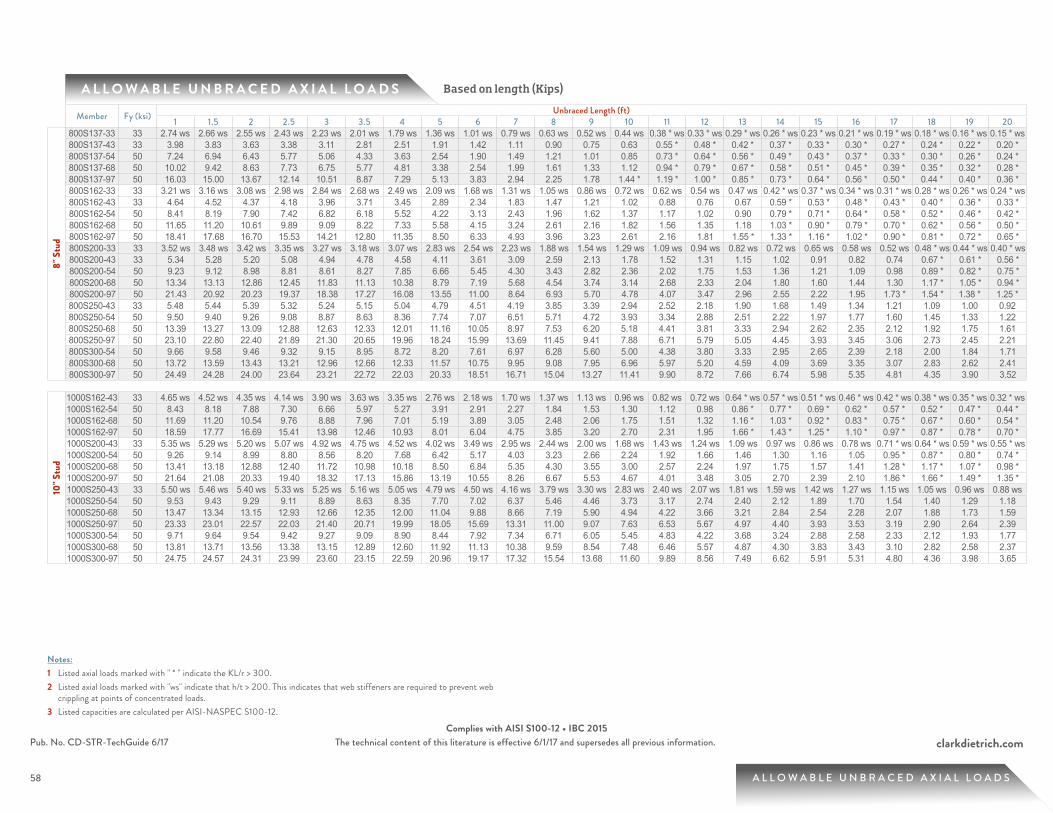
58
clarkdietrich.comPub. No. CD-STR-TechGuide 6/17 The technical content of this literature is effective 6/1/17 and supersedes all previous information.Complies with AISI S100-12 • IBC 2015
58 A L L O W A B L E U N B R A C E D A X I A L L O A D S
A L L O W A B L E U N B R A C E D A X I A L L O A D S Based on length (Kips)
Notes:1 Listed axial loads marked with " * " indicate the KL/r > 300.2 Listed axial loads marked with "ws" indicate that h/t > 200. This indicates that web stiffeners are required to prevent web
crippling at points of concentrated loads.3 Listed capacities are calculated per AISI-NASPEC S100-12.
Member Fy (ksi) Unbraced Length (ft)1 1.5 2 2.5 3 3.5 4 5 6 7 8 9 10 11 12 13 14 15 16 17 18 19 20
8" S
tud
800S137-33 33 2.74 ws 2.66 ws 2.55 ws 2.43 ws 2.23 ws 2.01 ws 1.79 ws 1.36 ws 1.01 ws 0.79 ws 0.63 ws 0.52 ws 0.44 ws 0.38 * ws 0.33 * ws 0.29 * ws 0.26 * ws 0.23 * ws 0.21 * ws 0.19 * ws 0.18 * ws 0.16 * ws 0.15 * ws800S137-43 33 3.98 3.83 3.63 3.38 3.11 2.81 2.51 1.91 1.42 1.11 0.90 0.75 0.63 0.55 * 0.48 * 0.42 * 0.37 * 0.33 * 0.30 * 0.27 * 0.24 * 0.22 * 0.20 * 800S137-54 50 7.24 6.94 6.43 5.77 5.06 4.33 3.63 2.54 1.90 1.49 1.21 1.01 0.85 0.73 * 0.64 * 0.56 * 0.49 * 0.43 * 0.37 * 0.33 * 0.30 * 0.26 * 0.24 * 800S137-68 50 10.02 9.42 8.63 7.73 6.75 5.77 4.81 3.38 2.54 1.99 1.61 1.33 1.12 0.94 * 0.79 * 0.67 * 0.58 * 0.51 * 0.45 * 0.39 * 0.35 * 0.32 * 0.28 * 800S137-97 50 16.03 15.00 13.67 12.14 10.51 8.87 7.29 5.13 3.83 2.94 2.25 1.78 1.44 * 1.19 * 1.00 * 0.85 * 0.73 * 0.64 * 0.56 * 0.50 * 0.44 * 0.40 * 0.36 * 800S162-33 33 3.21 ws 3.16 ws 3.08 ws 2.98 ws 2.84 ws 2.68 ws 2.49 ws 2.09 ws 1.68 ws 1.31 ws 1.05 ws 0.86 ws 0.72 ws 0.62 ws 0.54 ws 0.47 ws 0.42 * ws 0.37 * ws 0.34 * ws 0.31 * ws 0.28 * ws 0.26 * ws 0.24 * ws800S162-43 33 4.64 4.52 4.37 4.18 3.96 3.71 3.45 2.89 2.34 1.83 1.47 1.21 1.02 0.88 0.76 0.67 0.59 * 0.53 * 0.48 * 0.43 * 0.40 * 0.36 * 0.33 * 800S162-54 50 8.41 8.19 7.90 7.42 6.82 6.18 5.52 4.22 3.13 2.43 1.96 1.62 1.37 1.17 1.02 0.90 0.79 * 0.71 * 0.64 * 0.58 * 0.52 * 0.46 * 0.42 * 800S162-68 50 11.65 11.20 10.61 9.89 9.09 8.22 7.33 5.58 4.15 3.24 2.61 2.16 1.82 1.56 1.35 1.18 1.03 * 0.90 * 0.79 * 0.70 * 0.62 * 0.56 * 0.50 * 800S162-97 50 18.41 17.68 16.70 15.53 14.21 12.80 11.35 8.50 6.33 4.93 3.96 3.23 2.61 2.16 1.81 1.55 * 1.33 * 1.16 * 1.02 * 0.90 * 0.81 * 0.72 * 0.65 * 800S200-33 33 3.52 ws 3.48 ws 3.42 ws 3.35 ws 3.27 ws 3.18 ws 3.07 ws 2.83 ws 2.54 ws 2.23 ws 1.88 ws 1.54 ws 1.29 ws 1.09 ws 0.94 ws 0.82 ws 0.72 ws 0.65 ws 0.58 ws 0.52 ws 0.48 * ws 0.44 * ws 0.40 * ws800S200-43 33 5.34 5.28 5.20 5.08 4.94 4.78 4.58 4.11 3.61 3.09 2.59 2.13 1.78 1.52 1.31 1.15 1.02 0.91 0.82 0.74 0.67 * 0.61 * 0.56 * 800S200-54 50 9.23 9.12 8.98 8.81 8.61 8.27 7.85 6.66 5.45 4.30 3.43 2.82 2.36 2.02 1.75 1.53 1.36 1.21 1.09 0.98 0.89 * 0.82 * 0.75 * 800S200-68 50 13.34 13.13 12.86 12.45 11.83 11.13 10.38 8.79 7.19 5.68 4.54 3.74 3.14 2.68 2.33 2.04 1.80 1.60 1.44 1.30 1.17 * 1.05 * 0.94 * 800S200-97 50 21.43 20.92 20.23 19.37 18.38 17.27 16.08 13.55 11.00 8.64 6.93 5.70 4.78 4.07 3.47 2.96 2.55 2.22 1.95 1.73 * 1.54 * 1.38 * 1.25 * 800S250-43 33 5.48 5.44 5.39 5.32 5.24 5.15 5.04 4.79 4.51 4.19 3.85 3.39 2.94 2.52 2.18 1.90 1.68 1.49 1.34 1.21 1.09 1.00 0.92800S250-54 50 9.50 9.40 9.26 9.08 8.87 8.63 8.36 7.74 7.07 6.51 5.71 4.72 3.93 3.34 2.88 2.51 2.22 1.97 1.77 1.60 1.45 1.33 1.22800S250-68 50 13.39 13.27 13.09 12.88 12.63 12.33 12.01 11.16 10.05 8.97 7.53 6.20 5.18 4.41 3.81 3.33 2.94 2.62 2.35 2.12 1.92 1.75 1.61800S250-97 50 23.10 22.80 22.40 21.89 21.30 20.65 19.96 18.24 15.99 13.69 11.45 9.41 7.88 6.71 5.79 5.05 4.45 3.93 3.45 3.06 2.73 2.45 2.21800S300-54 50 9.66 9.58 9.46 9.32 9.15 8.95 8.72 8.20 7.61 6.97 6.28 5.60 5.00 4.38 3.80 3.33 2.95 2.65 2.39 2.18 2.00 1.84 1.71800S300-68 50 13.72 13.59 13.43 13.21 12.96 12.66 12.33 11.57 10.75 9.95 9.08 7.95 6.96 5.97 5.20 4.59 4.09 3.69 3.35 3.07 2.83 2.62 2.41800S300-97 50 24.49 24.28 24.00 23.64 23.21 22.72 22.03 20.33 18.51 16.71 15.04 13.27 11.41 9.90 8.72 7.66 6.74 5.98 5.35 4.81 4.35 3.90 3.52
10" S
tud
1000S162-43 33 4.65 ws 4.52 ws 4.35 ws 4.14 ws 3.90 ws 3.63 ws 3.35 ws 2.76 ws 2.18 ws 1.70 ws 1.37 ws 1.13 ws 0.96 ws 0.82 ws 0.72 ws 0.64 * ws 0.57 * ws 0.51 * ws 0.46 * ws 0.42 * ws 0.38 * ws 0.35 * ws 0.32 * ws1000S162-54 50 8.43 8.18 7.88 7.30 6.66 5.97 5.27 3.91 2.91 2.27 1.84 1.53 1.30 1.12 0.98 0.86 * 0.77 * 0.69 * 0.62 * 0.57 * 0.52 * 0.47 * 0.44 * 1000S162-68 50 11.69 11.20 10.54 9.76 8.88 7.96 7.01 5.19 3.89 3.05 2.48 2.06 1.75 1.51 1.32 1.16 * 1.03 * 0.92 * 0.83 * 0.75 * 0.67 * 0.60 * 0.54 * 1000S162-97 50 18.59 17.77 16.69 15.41 13.98 12.46 10.93 8.01 6.04 4.75 3.85 3.20 2.70 2.31 1.95 1.66 * 1.43 * 1.25 * 1.10 * 0.97 * 0.87 * 0.78 * 0.70 * 1000S200-43 33 5.35 ws 5.29 ws 5.20 ws 5.07 ws 4.92 ws 4.75 ws 4.52 ws 4.02 ws 3.49 ws 2.95 ws 2.44 ws 2.00 ws 1.68 ws 1.43 ws 1.24 ws 1.09 ws 0.97 ws 0.86 ws 0.78 ws 0.71 * ws 0.64 * ws 0.59 * ws 0.55 * ws1000S200-54 50 9.26 9.14 8.99 8.80 8.56 8.20 7.68 6.42 5.17 4.03 3.23 2.66 2.24 1.92 1.66 1.46 1.30 1.16 1.05 0.95 * 0.87 * 0.80 * 0.74 * 1000S200-68 50 13.41 13.18 12.88 12.40 11.72 10.98 10.18 8.50 6.84 5.35 4.30 3.55 3.00 2.57 2.24 1.97 1.75 1.57 1.41 1.28 * 1.17 * 1.07 * 0.98 * 1000S200-97 50 21.64 21.08 20.33 19.40 18.32 17.13 15.86 13.19 10.55 8.26 6.67 5.53 4.67 4.01 3.48 3.05 2.70 2.39 2.10 1.86 * 1.66 * 1.49 * 1.35 * 1000S250-43 33 5.50 ws 5.46 ws 5.40 ws 5.33 ws 5.25 ws 5.16 ws 5.05 ws 4.79 ws 4.50 ws 4.16 ws 3.79 ws 3.30 ws 2.83 ws 2.40 ws 2.07 ws 1.81 ws 1.59 ws 1.42 ws 1.27 ws 1.15 ws 1.05 ws 0.96 ws 0.88 ws1000S250-54 50 9.53 9.43 9.29 9.11 8.89 8.63 8.35 7.70 7.02 6.37 5.46 4.46 3.73 3.17 2.74 2.40 2.12 1.89 1.70 1.54 1.40 1.29 1.181000S250-68 50 13.47 13.34 13.15 12.93 12.66 12.35 12.00 11.04 9.88 8.66 7.19 5.90 4.94 4.22 3.66 3.21 2.84 2.54 2.28 2.07 1.88 1.73 1.591000S250-97 50 23.33 23.01 22.57 22.03 21.40 20.71 19.99 18.05 15.69 13.31 11.00 9.07 7.63 6.53 5.67 4.97 4.40 3.93 3.53 3.19 2.90 2.64 2.391000S300-54 50 9.71 9.64 9.54 9.42 9.27 9.09 8.90 8.44 7.92 7.34 6.71 6.05 5.45 4.83 4.22 3.68 3.24 2.88 2.58 2.33 2.12 1.93 1.771000S300-68 50 13.81 13.71 13.56 13.38 13.15 12.89 12.60 11.92 11.13 10.38 9.59 8.54 7.48 6.46 5.57 4.87 4.30 3.83 3.43 3.10 2.82 2.58 2.371000S300-97 50 24.75 24.57 24.31 23.99 23.60 23.15 22.59 20.96 19.17 17.32 15.54 13.68 11.60 9.89 8.56 7.49 6.62 5.91 5.31 4.80 4.36 3.98 3.65
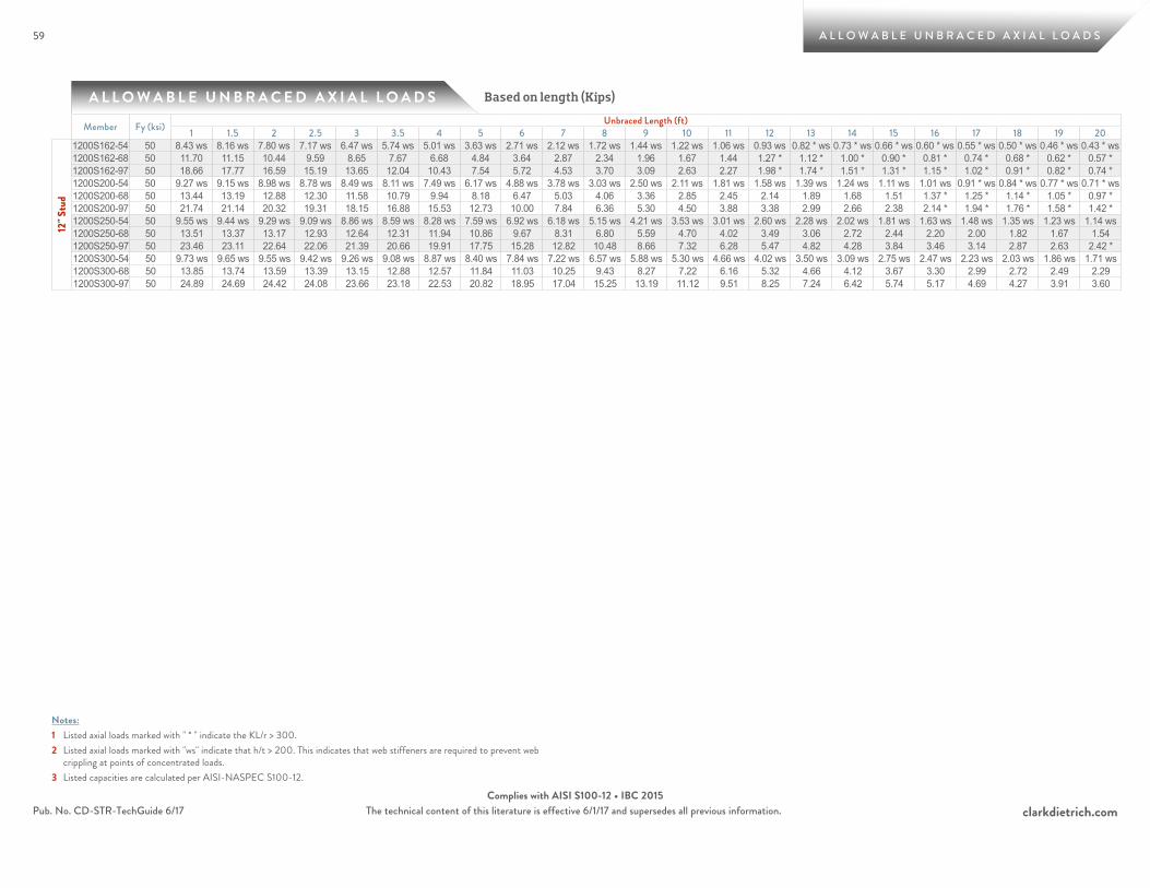
59
clarkdietrich.comPub. No. CD-STR-TechGuide 6/17 The technical content of this literature is effective 6/1/17 and supersedes all previous information.Complies with AISI S100-12 • IBC 2015
59 A L L O W A B L E U N B R A C E D A X I A L L O A D S
A L L O W A B L E U N B R A C E D A X I A L L O A D S Based on length (Kips)
Notes:1 Listed axial loads marked with " * " indicate the KL/r > 300.2 Listed axial loads marked with "ws" indicate that h/t > 200. This indicates that web stiffeners are required to prevent web
crippling at points of concentrated loads.3 Listed capacities are calculated per AISI-NASPEC S100-12.
Member Fy (ksi) Unbraced Length (ft)1 1.5 2 2.5 3 3.5 4 5 6 7 8 9 10 11 12 13 14 15 16 17 18 19 20
12" S
tud
1200S162-54 50 8.43 ws 8.16 ws 7.80 ws 7.17 ws 6.47 ws 5.74 ws 5.01 ws 3.63 ws 2.71 ws 2.12 ws 1.72 ws 1.44 ws 1.22 ws 1.06 ws 0.93 ws 0.82 * ws 0.73 * ws 0.66 * ws 0.60 * ws 0.55 * ws 0.50 * ws 0.46 * ws 0.43 * ws1200S162-68 50 11.70 11.15 10.44 9.59 8.65 7.67 6.68 4.84 3.64 2.87 2.34 1.96 1.67 1.44 1.27 * 1.12 * 1.00 * 0.90 * 0.81 * 0.74 * 0.68 * 0.62 * 0.57 * 1200S162-97 50 18.66 17.77 16.59 15.19 13.65 12.04 10.43 7.54 5.72 4.53 3.70 3.09 2.63 2.27 1.98 * 1.74 * 1.51 * 1.31 * 1.15 * 1.02 * 0.91 * 0.82 * 0.74 * 1200S200-54 50 9.27 ws 9.15 ws 8.98 ws 8.78 ws 8.49 ws 8.11 ws 7.49 ws 6.17 ws 4.88 ws 3.78 ws 3.03 ws 2.50 ws 2.11 ws 1.81 ws 1.58 ws 1.39 ws 1.24 ws 1.11 ws 1.01 ws 0.91 * ws 0.84 * ws 0.77 * ws 0.71 * ws1200S200-68 50 13.44 13.19 12.88 12.30 11.58 10.79 9.94 8.18 6.47 5.03 4.06 3.36 2.85 2.45 2.14 1.89 1.68 1.51 1.37 * 1.25 * 1.14 * 1.05 * 0.97 * 1200S200-97 50 21.74 21.14 20.32 19.31 18.15 16.88 15.53 12.73 10.00 7.84 6.36 5.30 4.50 3.88 3.38 2.99 2.66 2.38 2.14 * 1.94 * 1.76 * 1.58 * 1.42 * 1200S250-54 50 9.55 ws 9.44 ws 9.29 ws 9.09 ws 8.86 ws 8.59 ws 8.28 ws 7.59 ws 6.92 ws 6.18 ws 5.15 ws 4.21 ws 3.53 ws 3.01 ws 2.60 ws 2.28 ws 2.02 ws 1.81 ws 1.63 ws 1.48 ws 1.35 ws 1.23 ws 1.14 ws1200S250-68 50 13.51 13.37 13.17 12.93 12.64 12.31 11.94 10.86 9.67 8.31 6.80 5.59 4.70 4.02 3.49 3.06 2.72 2.44 2.20 2.00 1.82 1.67 1.541200S250-97 50 23.46 23.11 22.64 22.06 21.39 20.66 19.91 17.75 15.28 12.82 10.48 8.66 7.32 6.28 5.47 4.82 4.28 3.84 3.46 3.14 2.87 2.63 2.42 * 1200S300-54 50 9.73 ws 9.65 ws 9.55 ws 9.42 ws 9.26 ws 9.08 ws 8.87 ws 8.40 ws 7.84 ws 7.22 ws 6.57 ws 5.88 ws 5.30 ws 4.66 ws 4.02 ws 3.50 ws 3.09 ws 2.75 ws 2.47 ws 2.23 ws 2.03 ws 1.86 ws 1.71 ws1200S300-68 50 13.85 13.74 13.59 13.39 13.15 12.88 12.57 11.84 11.03 10.25 9.43 8.27 7.22 6.16 5.32 4.66 4.12 3.67 3.30 2.99 2.72 2.49 2.291200S300-97 50 24.89 24.69 24.42 24.08 23.66 23.18 22.53 20.82 18.95 17.04 15.25 13.19 11.12 9.51 8.25 7.24 6.42 5.74 5.17 4.69 4.27 3.91 3.60
F L O O R J O I S T F R A M I N G
66
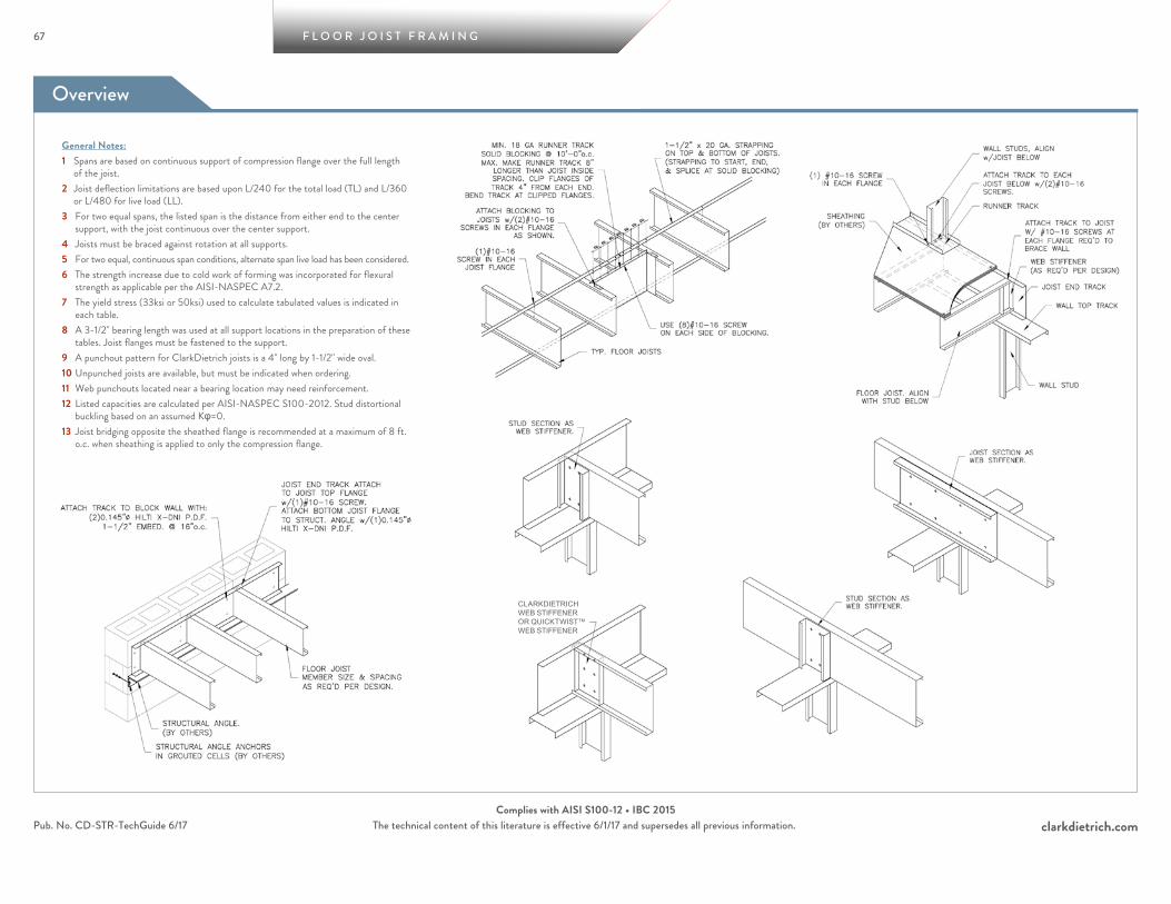
Overview
67 F L O O R J O I S T F R A M I N G
clarkdietrich.comPub. No. CD-STR-TechGuide 6/17 The technical content of this literature is effective 6/1/17 and supersedes all previous information.Complies with AISI S100-12 • IBC 2015
CLARKDIETRICH WEB STIFFENER OR QUICKTWIST™ WEB STIFFENER
General Notes:1 Spans are based on continuous support of compression flange over the full length
of the joist.2 Joist deflection limitations are based upon L/240 for the total load (TL) and L/360
or L/480 for live load (LL).3 For two equal spans, the listed span is the distance from either end to the center
support, with the joist continuous over the center support.4 Joists must be braced against rotation at all supports.5 For two equal, continuous span conditions, alternate span live load has been considered.6 The strength increase due to cold work of forming was incorporated for flexural
strength as applicable per the AISI-NASPEC A7.2.7 The yield stress (33ksi or 50ksi) used to calculate tabulated values is indicated in
each table.8 A 3-1/2" bearing length was used at all support locations in the preparation of these
tables. Joist flanges must be fastened to the support.9 A punchout pattern for ClarkDietrich joists is a 4" long by 1-1/2" wide oval.10 Unpunched joists are available, but must be indicated when ordering.11 Web punchouts located near a bearing location may need reinforcement.12 Listed capacities are calculated per AISI-NASPEC S100-2012. Stud distortional
buckling based on an assumed Kφ=0.13 Joist bridging opposite the sheathed flange is recommended at a maximum of 8 ft.
o.c. when sheathing is applied to only the compression flange.
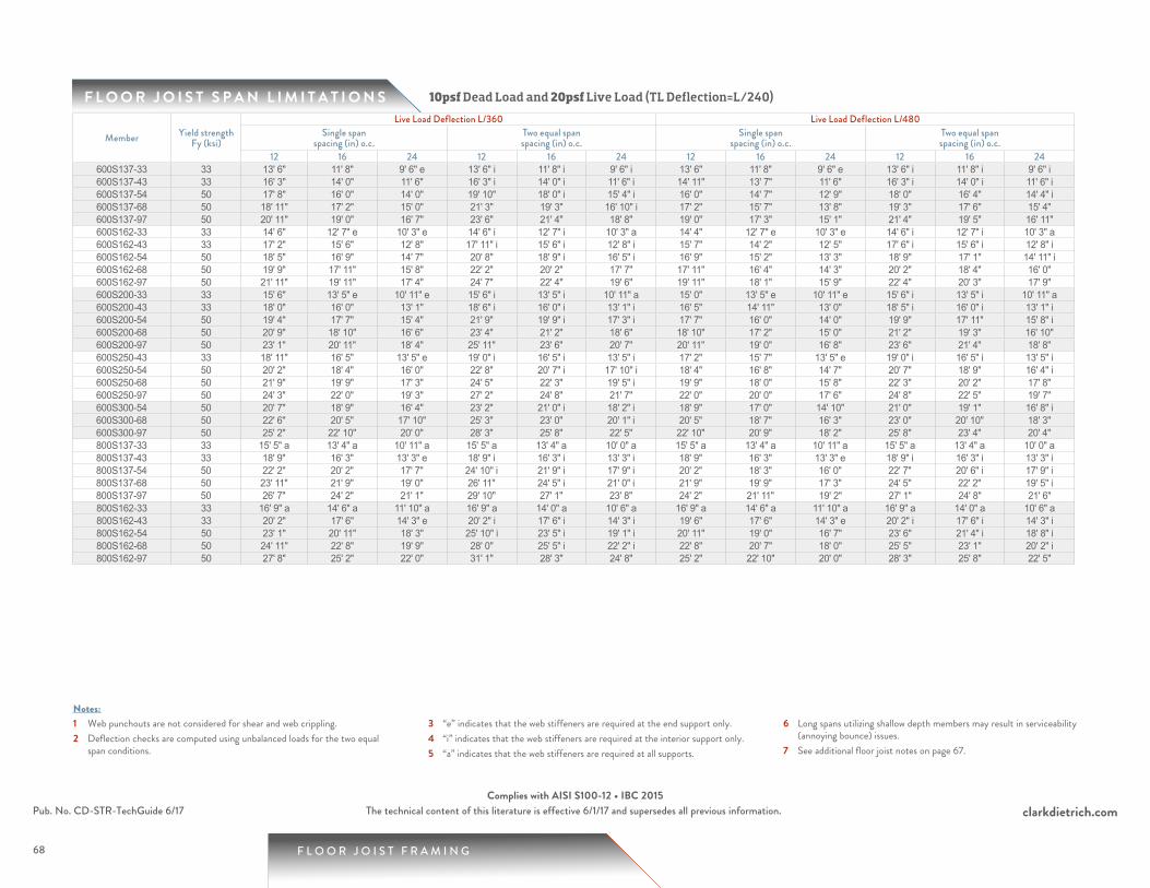
68
F L O O R J O I S T S P A N L I M I T A T I O N S
1 Web punchouts are not considered for shear and web crippling.2 Deflection checks are computed using unbalanced loads for the two equal
span conditions.
3 “e” indicates that the web stiffeners are required at the end support only.4 “i” indicates that the web stiffeners are required at the interior support only.5 “a” indicates that the web stiffeners are required at all supports.
6 Long spans utilizing shallow depth members may result in serviceability (annoying bounce) issues.
7 See additional floor joist notes on page 67.
Notes:
10psf Dead Load and 20psf Live Load (TL Deflection=L/240)
F L O O R J O I S T F R A M I N G
clarkdietrich.comPub. No. CD-STR-TechGuide 6/17 The technical content of this literature is effective 6/1/17 and supersedes all previous information.Complies with AISI S100-12 • IBC 2015
Member Yield strength Fy (ksi)
Live Load Deflection L/360 Live Load Deflection L/480Single span
spacing (in) o.c.Two equal spanspacing (in) o.c.
Single spanspacing (in) o.c.
Two equal spanspacing (in) o.c.
12 16 24 12 16 24 12 16 24 12 16 24600S137-33 33 13' 6" 11' 8" 9' 6" e 13' 6" i 11' 8" i 9' 6" i 13' 6" 11' 8" 9' 6" e 13' 6" i 11' 8" i 9' 6" i600S137-43 33 16' 3" 14' 0" 11' 6" 16' 3" i 14' 0" i 11' 6" i 14' 11" 13' 7" 11' 6" 16' 3" i 14' 0" i 11' 6" i600S137-54 50 17' 8" 16' 0" 14' 0" 19' 10" 18' 0" i 15' 4" i 16' 0" 14' 7" 12' 9" 18' 0" 16' 4" 14' 4" i600S137-68 50 18' 11" 17' 2" 15' 0" 21' 3" 19' 3" 16' 10" i 17' 2" 15' 7" 13' 8" 19' 3" 17' 6" 15' 4" 600S137-97 50 20' 11" 19' 0" 16' 7" 23' 6" 21' 4" 18' 8" 19' 0" 17' 3" 15' 1" 21' 4" 19' 5" 16' 11" 600S162-33 33 14' 6" 12' 7" e 10' 3" e 14' 6" i 12' 7" i 10' 3" a 14' 4" 12' 7" e 10' 3" e 14' 6" i 12' 7" i 10' 3" a600S162-43 33 17' 2" 15' 6" 12' 8" 17' 11" i 15' 6" i 12' 8" i 15' 7" 14' 2" 12' 5" 17' 6" i 15' 6" i 12' 8" i600S162-54 50 18' 5" 16' 9" 14' 7" 20' 8" 18' 9" i 16' 5" i 16' 9" 15' 2" 13' 3" 18' 9" 17' 1" 14' 11" i600S162-68 50 19' 9" 17' 11" 15' 8" 22' 2" 20' 2" 17' 7" 17' 11" 16' 4" 14' 3" 20' 2" 18' 4" 16' 0" 600S162-97 50 21' 11" 19' 11" 17' 4" 24' 7" 22' 4" 19' 6" 19' 11" 18' 1" 15' 9" 22' 4" 20' 3" 17' 9" 600S200-33 33 15' 6" 13' 5" e 10' 11" e 15' 6" i 13' 5" i 10' 11" a 15' 0" 13' 5" e 10' 11" e 15' 6" i 13' 5" i 10' 11" a600S200-43 33 18' 0" 16' 0" 13' 1" 18' 6" i 16' 0" i 13' 1" i 16' 5" 14' 11" 13' 0" 18' 5" i 16' 0" i 13' 1" i600S200-54 50 19' 4" 17' 7" 15' 4" 21' 9" 19' 9" i 17' 3" i 17' 7" 16' 0" 14' 0" 19' 9" 17' 11" 15' 8" i600S200-68 50 20' 9" 18' 10" 16' 6" 23' 4" 21' 2" 18' 6" 18' 10" 17' 2" 15' 0" 21' 2" 19' 3" 16' 10" 600S200-97 50 23' 1" 20' 11" 18' 4" 25' 11" 23' 6" 20' 7" 20' 11" 19' 0" 16' 8" 23' 6" 21' 4" 18' 8" 600S250-43 33 18' 11" 16' 5" 13' 5" e 19' 0" i 16' 5" i 13' 5" i 17' 2" 15' 7" 13' 5" e 19' 0" i 16' 5" i 13' 5" i600S250-54 50 20' 2" 18' 4" 16' 0" 22' 8" 20' 7" i 17' 10" i 18' 4" 16' 8" 14' 7" 20' 7" 18' 9" 16' 4" i600S250-68 50 21' 9" 19' 9" 17' 3" 24' 5" 22' 3" 19' 5" i 19' 9" 18' 0" 15' 8" 22' 3" 20' 2" 17' 8" 600S250-97 50 24' 3" 22' 0" 19' 3" 27' 2" 24' 8" 21' 7" 22' 0" 20' 0" 17' 6" 24' 8" 22' 5" 19' 7" 600S300-54 50 20' 7" 18' 9" 16' 4" 23' 2" 21' 0" i 18' 2" i 18' 9" 17' 0" 14' 10" 21' 0" 19' 1" 16' 8" i600S300-68 50 22' 6" 20' 5" 17' 10" 25' 3" 23' 0" 20' 1" i 20' 5" 18' 7" 16' 3" 23' 0" 20' 10" 18' 3" 600S300-97 50 25' 2" 22' 10" 20' 0" 28' 3" 25' 8" 22' 5" 22' 10" 20' 9" 18' 2" 25' 8" 23' 4" 20' 4" 800S137-33 33 15' 5" a 13' 4" a 10' 11" a 15' 5" a 13' 4" a 10' 0" a 15' 5" a 13' 4" a 10' 11" a 15' 5" a 13' 4" a 10' 0" a800S137-43 33 18' 9" 16' 3" 13' 3" e 18' 9" i 16' 3" i 13' 3" i 18' 9" 16' 3" 13' 3" e 18' 9" i 16' 3" i 13' 3" i800S137-54 50 22' 2" 20' 2" 17' 7" 24' 10" i 21' 9" i 17' 9" i 20' 2" 18' 3" 16' 0" 22' 7" 20' 6" i 17' 9" i800S137-68 50 23' 11" 21' 9" 19' 0" 26' 11" 24' 5" i 21' 0" i 21' 9" 19' 9" 17' 3" 24' 5" 22' 2" 19' 5" i800S137-97 50 26' 7" 24' 2" 21' 1" 29' 10" 27' 1" 23' 8" 24' 2" 21' 11" 19' 2" 27' 1" 24' 8" 21' 6" 800S162-33 33 16' 9" a 14' 6" a 11' 10" a 16' 9" a 14' 0" a 10' 6" a 16' 9" a 14' 6" a 11' 10" a 16' 9" a 14' 0" a 10' 6" a800S162-43 33 20' 2" 17' 6" 14' 3" e 20' 2" i 17' 6" i 14' 3" i 19' 6" 17' 6" 14' 3" e 20' 2" i 17' 6" i 14' 3" i800S162-54 50 23' 1" 20' 11" 18' 3" 25' 10" i 23' 5" i 19' 1" i 20' 11" 19' 0" 16' 7" 23' 6" 21' 4" i 18' 8" i800S162-68 50 24' 11" 22' 8" 19' 9" 28' 0" 25' 5" i 22' 2" i 22' 8" 20' 7" 18' 0" 25' 5" 23' 1" 20' 2" i800S162-97 50 27' 8" 25' 2" 22' 0" 31' 1" 28' 3" 24' 8" 25' 2" 22' 10" 20' 0" 28' 3" 25' 8" 22' 5"

69
F L O O R J O I S T S P A N L I M I T A T I O N S 10psf Dead Load and 20psf Live Load (TL Deflection=L/240)
F L O O R J O I S T F R A M I N G
clarkdietrich.comPub. No. CD-STR-TechGuide 6/17 The technical content of this literature is effective 6/1/17 and supersedes all previous information.Complies with AISI S100-12 • IBC 2015
1 Web punchouts are not considered for shear and web crippling.2 Deflection checks are computed using unbalanced loads for the two equal
span conditions.
3 “e” indicates that the web stiffeners are required at the end support only.4 “i” indicates that the web stiffeners are required at the interior support only.5 “a” indicates that the web stiffeners are required at all supports.
6 Long spans utilizing shallow depth members may result in serviceability (annoying bounce) issues.
7 See additional floor joist notes on page 67.
Notes:
Member Yield strength Fy (ksi)
Live Load Deflection L/360 Live Load Deflection L/480Single span
spacing (in) o.c.Two equal spanspacing (in) o.c.
Single spanspacing (in) o.c.
Two equal spanspacing (in) o.c.
12 16 24 12 16 24 12 16 24 12 16 24800S200-33 33 18' 0" a 15' 7" a 12' 8" a 17' 10" a 14' 7" a 10' 10" a 18' 0" a 15' 7" a 12' 8" a 17' 10" a 14' 7" a 10' 10" a800S200-43 33 21' 7" 18' 8" 15' 3" e 21' 7" i 18' 8" i 15' 3" a 20' 7" 18' 8" 15' 3" e 21' 7" i 18' 8" i 15' 3" a800S200-54 50 24' 4" 22' 1" 19' 4" 27' 3" i 24' 10" i 20' 5" i 22' 1" 20' 1" 17' 6" 24' 10" 22' 6" i 19' 8" i800S200-68 50 26' 1" 23' 9" 20' 9" 29' 4" 26' 8" 23' 3" i 23' 9" 21' 7" 18' 10" 26' 8" 24' 2" 21' 2" 800S200-97 50 29' 0" 26' 5" 23' 1" 32' 7" 29' 7" 25' 11" 26' 5" 24' 0" 20' 11" 29' 7" 26' 11" 23' 6" 800S250-43 33 22' 2" 19' 2" e 15' 8" e 22' 2" i 19' 2" i 15' 8" a 21' 5" 19' 2" e 15' 8" e 22' 2" i 19' 2" i 15' 8" a800S250-54 50 25' 3" 22' 11" 20' 1" 28' 4" i 25' 7" i 20' 10" i 22' 11" 20' 10" 18' 3" 25' 9" 23' 5" i 20' 5" i800S250-68 50 27' 3" 24' 9" 21' 7" 30' 7" 27' 9" i 24' 3" i 24' 9" 22' 6" 19' 8" 27' 9" 25' 3" 22' 1" i800S250-97 50 30' 4" 27' 7" 24' 1" 34' 1" 30' 11" 27' 1" 27' 7" 25' 1" 21' 11" 30' 11" 28' 2" 24' 7" 800S300-54 50 25' 10" 23' 5" 20' 6" 29' 0" i 25' 11" i 21' 2" i 23' 5" 21' 4" 18' 7" 26' 4" i 23' 11" i 20' 11" i800S300-68 50 28' 0" 25' 6" 22' 3" 31' 6" 28' 7" i 24' 10" i 25' 6" 23' 2" 20' 3" 28' 7" 26' 0" 22' 8" i800S300-97 50 31' 5" 28' 6" 24' 11" 35' 3" 32' 0" 28' 0" 28' 6" 25' 11" 22' 8" 32' 0" 29' 1" 25' 5" 1000S162-43 33 22' 4" a 19' 4" a 15' 10" a 22' 4" a 19' 4" a 15' 9" a 22' 4" a 19' 4" a 15' 10" a 22' 4" a 19' 4" a 15' 9" a1000S162-54 50 27' 5" 24' 10" 21' 2" 30' 0" i 25' 11" i 21' 2" i 24' 10" 22' 7" 19' 9" 27' 11" i 25' 4" i 21' 2" i1000S162-68 50 29' 8" 27' 0" 23' 7" 33' 4" i 30' 3" i 25' 0" i 27' 0" 24' 6" 21' 5" 30' 3" 27' 6" i 24' 0" i1000S162-97 50 33' 4" 30' 4" 26' 6" 37' 5" 34' 0" 29' 9" 30' 4" 27' 6" 24' 1" 34' 0" 30' 11" 27' 0" 1000S200-43 33 24' 1" a 20' 11" a 17' 1" a 24' 1" a 20' 11" a 16' 6" a 24' 1" a 20' 11" a 17' 1" a 24' 1" a 20' 11" a 16' 6" a1000S200-54 50 28' 8" 26' 0" 22' 9" 32' 2" i 27' 11" i 22' 9" i 26' 0" 23' 8" 20' 8" 29' 3" i 26' 7" i 22' 9" i1000S200-68 50 31' 0" 28' 2" 24' 7" 34' 10" i 31' 8" i 26' 9" i 28' 2" 25' 7" 22' 4" 31' 8" 28' 9" 25' 1" i1000S200-97 50 34' 10" 31' 8" 27' 8" 39' 1" 35' 6" 31' 0" 31' 8" 28' 9" 25' 1" 35' 6" 32' 3" 28' 2" 1000S250-54 50 30' 3" 27' 6" 23' 5" 33' 1" i 28' 8" i 23' 5" i 27' 6" 25' 0" 21' 10" 30' 10" i 28' 0" i 23' 5" i1000S250-68 50 32' 6" 29' 7" 25' 10" 36' 6" i 33' 2" i 27' 6" i 29' 7" 26' 10" 23' 5" 33' 2" 30' 2" i 26' 4" i1000S250-97 50 36' 3" 32' 11" 28' 9" 40' 9" 37' 0" 32' 4" 32' 11" 29' 11" 26' 2" 37' 0" 33' 7" 29' 4" 1000S300-54 50 30' 10" 28' 0" 23' 9" 33' 7" i 29' 1" i 23' 9" i 28' 0" 25' 6" 22' 3" 31' 6" i 28' 7" i 23' 9" i1000S300-68 50 33' 5" 30' 4" 26' 6" 37' 6" i 34' 1" i 28' 0" i 30' 4" 27' 7" 24' 1" 34' 1" 31' 0" i 27' 1" i1000S300-97 50 37' 5" 34' 0" 29' 8" 42' 0" 38' 2" 33' 4" i 34' 0" 30' 11" 27' 0" 38' 2" 34' 8" 30' 4" 1200S162-54 50 31' 6" a 27' 11" a 22' 10" a 32' 3" a 27' 11" a 22' 10" a 28' 7" a 26' 0" a 22' 9" a 32' 2" a 27' 11" a 22' 10" a1200S162-68 50 34' 3" 31' 1" 27' 1" 38' 4" i 33' 3" i 27' 1" i 31' 1" 28' 3" 24' 8" 34' 11" i 31' 9" i 27' 1" i1200S162-97 50 38' 10" 35' 3" 30' 10" 43' 7" 39' 7" 34' 7" i 35' 3" 32' 0" 28' 0" 39' 7" 36' 0" 31' 5" 1200S200-54 50 32' 11" a 29' 11" a 24' 8" a 34' 11" a 30' 3" a 24' 8" a 29' 11" a 27' 2" a 23' 9" a 33' 7" a 30' 3" a 24' 8" a1200S200-68 50 35' 9" 32' 5" 28' 4" 40' 1" i 35' 9" i 29' 2" i 32' 5" 29' 6" 25' 9" 36' 5" 33' 1" i 28' 11" i1200S200-97 50 40' 5" 36' 8" 32' 1" 45' 4" 41' 3" 36' 0" i 36' 8" 33' 4" 29' 2" 41' 3" 37' 5" 32' 9"
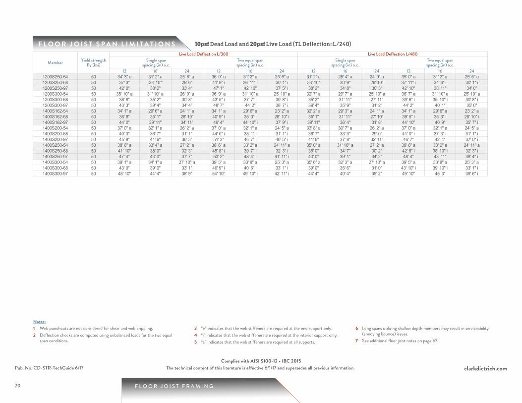
70
F L O O R J O I S T S P A N L I M I T A T I O N S
1 Web punchouts are not considered for shear and web crippling.2 Deflection checks are computed using unbalanced loads for the two equal
span conditions.
3 “e” indicates that the web stiffeners are required at the end support only.4 “i” indicates that the web stiffeners are required at the interior support only.5 “a” indicates that the web stiffeners are required at all supports.
6 Long spans utilizing shallow depth members may result in serviceability (annoying bounce) issues.
7 See additional floor joist notes on page 67.
Notes:
10psf Dead Load and 20psf Live Load (TL Deflection=L/240)
F L O O R J O I S T F R A M I N G
clarkdietrich.comPub. No. CD-STR-TechGuide 6/17 The technical content of this literature is effective 6/1/17 and supersedes all previous information.Complies with AISI S100-12 • IBC 2015
Member Yield strength Fy (ksi)
Live Load Deflection L/360 Live Load Deflection L/480Single span
spacing (in) o.c.Two equal spanspacing (in) o.c.
Single spanspacing (in) o.c.
Two equal spanspacing (in) o.c.
12 16 24 12 16 24 12 16 24 12 16 241200S250-54 50 34' 3" a 31' 2" a 25' 6" a 36' 0" a 31' 2" a 25' 6" a 31' 2" a 28' 4" a 24' 9" a 35' 0" a 31' 2" a 25' 6" a1200S250-68 50 37' 3" 33' 10" 29' 6" 41' 9" i 36' 11" i 30' 1" i 33' 10" 30' 9" 26' 10" 37' 11" i 34' 6" i 30' 1" i1200S250-97 50 42' 0" 38' 2" 33' 4" 47' 1" 42' 10" 37' 5" i 38' 2" 34' 8" 30' 3" 42' 10" 38' 11" 34' 0" 1200S300-54 50 35' 10" a 31' 10" a 26' 0" a 36' 9" a 31' 10" a 25' 10" a 32' 7" a 29' 7" a 25' 10" a 36' 7" a 31' 10" a 25' 10" a1200S300-68 50 38' 8" 35' 2" 30' 8" 43' 5" i 37' 7" i 30' 8" i 35' 2" 31' 11" 27' 11" 39' 6" i 35' 10" i 30' 8" i1200S300-97 50 43' 3" 39' 4" 34' 4" 48' 7" 44' 2" 38' 7" i 39' 4" 35' 9" 31' 2" 44' 2" 40' 1" 35' 0" 1400S162-54 50 34' 1" a 29' 6" a 24' 1" a 34' 1" a 29' 6" a 23' 2" a 32' 2" a 29' 3" a 24' 1" a 34' 1" a 29' 6" a 23' 2" a1400S162-68 50 38' 8" 35' 1" 28' 10" 40' 9" i 35' 3" i 28' 10" i 35' 1" 31' 11" 27' 10" 39' 5" i 35' 3" i 28' 10" i1400S162-97 50 44' 0" 39' 11" 34' 11" 49' 4" 44' 10" i 37' 9" i 39' 11" 36' 4" 31' 8" 44' 10" 40' 9" 35' 7" i1400S200-54 50 37' 0" a 32' 1" a 26' 2" a 37' 0" a 32' 1" a 24' 5" a 33' 8" a 30' 7" a 26' 2" a 37' 0" a 32' 1" a 24' 5" a1400S200-68 50 40' 3" 36' 7" 31' 1" 44' 0" i 38' 1" i 31' 1" i 36' 7" 33' 3" 29' 0" 41' 0" i 37' 3" i 31' 1" i1400S200-97 50 45' 8" 41' 6" 36' 3" 51' 3" 46' 7" i 40' 5" i 41' 6" 37' 8" 32' 11" 46' 7" 42' 4" 37' 0" i1400S250-54 50 38' 6" a 33' 4" a 27' 2" a 38' 6" a 33' 2" a 24' 11" a 35' 0" a 31' 10" a 27' 2" a 38' 6" a 33' 2" a 24' 11" a1400S250-68 50 41' 10" 38' 0" 32' 3" 45' 8" i 39' 7" i 32' 3" i 38' 0" 34' 7" 30' 2" 42' 8" i 38' 10" i 32' 3" i1400S250-97 50 47' 4" 43' 0" 37' 7" 53' 2" 48' 4" i 41' 11" i 43' 0" 39' 1" 34' 2" 48' 4" 43' 11" 38' 4" i1400S300-54 50 39' 1" a 34' 1" a 27' 10" a 39' 5" a 33' 8" a 25' 3" a 35' 6" a 32' 3" a 27' 10" a 39' 5" a 33' 8" a 25' 3" a1400S300-68 50 43' 0" 39' 0" 33' 1" 46' 9" i 40' 6" i 33' 1" i 39' 0" 35' 6" 31' 0" 43' 10" i 39' 10" i 33' 1" i1400S300-97 50 48' 10" 44' 4" 38' 9" 54' 10" 49' 10" i 42' 11" i 44' 4" 40' 4" 35' 2" 49' 10" 45' 3" 39' 6" i
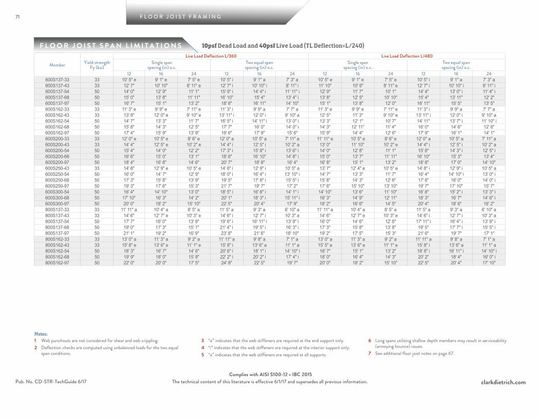
71
F L O O R J O I S T S P A N L I M I T A T I O N S
F L O O R J O I S T F R A M I N G
clarkdietrich.comPub. No. CD-STR-TechGuide 6/17 The technical content of this literature is effective 6/1/17 and supersedes all previous information.Complies with AISI S100-12 • IBC 2015
1 Web punchouts are not considered for shear and web crippling.2 Deflection checks are computed using unbalanced loads for the two equal
span conditions.
3 “e” indicates that the web stiffeners are required at the end support only.4 “i” indicates that the web stiffeners are required at the interior support only.5 “a” indicates that the web stiffeners are required at all supports.
6 Long spans utilizing shallow depth members may result in serviceability (annoying bounce) issues.
7 See additional floor joist notes on page 67.
Notes:
10psf Dead Load and 40psf Live Load (TL Deflection=L/240)
Member Yield strength Fy (ksi)
Live Load Deflection L/360 Live Load Deflection L/480Single span
spacing (in) o.c.Two equal spanspacing (in) o.c.
Single spanspacing (in) o.c.
Two equal spanspacing (in) o.c.
12 16 24 12 16 24 12 16 24 12 16 24600S137-33 33 10' 5" e 9' 1" e 7' 5" e 10' 5" i 9' 1" a 7' 3" a 10' 5" e 9' 1" e 7' 5" e 10' 5" i 9' 1" a 7' 3" a600S137-43 33 12' 7" 10' 10" 8' 11" e 12' 7" i 10' 10" i 8' 11" i 11' 10" 10' 9" 8' 11" e 12' 7" i 10' 10" i 8' 11" i600S137-54 50 14' 0" 12' 9" 11' 1" 15' 9" i 14' 4" i 11' 11" i 12' 9" 11' 7" 10' 1" 14' 4" 13' 0" i 11' 4" i600S137-68 50 15' 0" 13' 8" 11' 11" 16' 10" 15' 4" 13' 4" i 13' 8" 12' 5" 10' 10" 15' 4" 13' 11" 12' 2" 600S137-97 50 16' 7" 15' 1" 13' 2" 18' 8" 16' 11" 14' 10" 15' 1" 13' 8" 12' 0" 16' 11" 15' 5" 13' 5" 600S162-33 33 11' 3" e 9' 9" e 7' 11" e 11' 3" i 9' 9" a 7' 7" a 11' 3" e 9' 9" e 7' 11" e 11' 3" i 9' 9" a 7' 7" a600S162-43 33 13' 8" 12' 0" e 9' 10" e 13' 11" i 12' 0" i 9' 10" a 12' 5" 11' 3" 9' 10" e 13' 11" i 12' 0" i 9' 10" a600S162-54 50 14' 7" 13' 3" 11' 7" 16' 5" i 14' 11" i 13' 0" i 13' 3" 12' 1" 10' 7" 14' 11" 13' 7" i 11' 10" i600S162-68 50 15' 8" 14' 3" 12' 5" 17' 7" 16' 0" 14' 0" i 14' 3" 12' 11" 11' 4" 16' 0" 14' 6" 12' 8" 600S162-97 50 17' 4" 15' 9" 13' 9" 19' 6" 17' 9" 15' 6" 15' 9" 14' 4" 12' 6" 17' 9" 16' 1" 14' 1" 600S200-33 33 12' 0" e 10' 5" e 8' 6" e 12' 0" a 10' 5" a 7' 11" a 11' 11" e 10' 5" e 8' 6" e 12' 0" a 10' 5" a 7' 11" a600S200-43 33 14' 4" 12' 5" e 10' 2" e 14' 4" i 12' 5" i 10' 2" a 13' 0" 11' 10" 10' 2" e 14' 4" i 12' 5" i 10' 2" a600S200-54 50 15' 4" 14' 0" 12' 2" 17' 3" i 15' 8" i 13' 6" i 14' 0" 12' 8" 11' 1" 15' 8" 14' 3" i 12' 5" i600S200-68 50 16' 6" 15' 0" 13' 1" 18' 6" 16' 10" 14' 8" i 15' 0" 13' 7" 11' 11" 16' 10" 15' 3" 13' 4" 600S200-97 50 18' 4" 16' 8" 14' 6" 20' 7" 18' 8" 16' 4" 16' 8" 15' 1" 13' 2" 18' 8" 17' 0" 14' 10" 600S250-43 33 14' 8" 12' 9" e 10' 5" e 14' 8" i 12' 9" i 10' 5" a 13' 7" 12' 4" e 10' 5" e 14' 8" i 12' 9" i 10' 5" a600S250-54 50 16' 0" 14' 7" 12' 9" 18' 0" i 16' 4" i 13' 10" i 14' 7" 13' 3" 11' 7" 16' 4" 14' 10" i 13' 0" i600S250-68 50 17' 3" 15' 8" 13' 9" 19' 5" 17' 8" i 15' 5" i 15' 8" 14' 3" 12' 6" 17' 8" 16' 0" 14' 0" i600S250-97 50 19' 3" 17' 6" 15' 3" 21' 7" 19' 7" 17' 2" 17' 6" 15' 10" 13' 10" 19' 7" 17' 10" 15' 7" 600S300-54 50 16' 4" 14' 10" 13' 0" 18' 5" i 16' 8" i 14' 1" i 14' 10" 13' 6" 11' 10" 16' 8" 15' 2" i 13' 3" i600S300-68 50 17' 10" 16' 3" 14' 2" 20' 1" 18' 3" i 15' 11" i 16' 3" 14' 9" 12' 11" 18' 3" 16' 7" 14' 6" i600S300-97 50 20' 0" 18' 2" 15' 10" 22' 5" 20' 4" 17' 9" 18' 2" 16' 6" 14' 5" 20' 4" 18' 6" 16' 2" 800S137-33 33 11' 11" a 10' 4" a 8' 5" a 11' 5" a 9' 3" a 6' 10" a 11' 11" a 10' 4" a 8' 5" a 11' 5" a 9' 3" a 6' 10" a800S137-43 33 14' 6" 12' 7" e 10' 3" e 14' 6" i 12' 7" i 10' 3" a 14' 6" 12' 7" e 10' 3" e 14' 6" i 12' 7" i 10' 3" a800S137-54 50 17' 7" 16' 0" 13' 9" 19' 6" i 16' 11" i 13' 9" i 16' 0" 14' 6" 12' 8" 17' 11" i 16' 4" i 13' 9" i800S137-68 50 19' 0" 17' 3" 15' 1" 21' 4" i 19' 5" i 16' 3" i 17' 3" 15' 8" 13' 8" 19' 5" 17' 7" i 15' 5" i800S137-97 50 21' 1" 19' 2" 16' 9" 23' 8" 21' 6" 18' 10" 19' 2" 17' 5" 15' 3" 21' 6" 19' 7" 17' 1" 800S162-33 33 13' 0" a 11' 3" a 9' 2" a 11' 11" a 9' 8" a 7' 1" a 13' 0" a 11' 3" a 9' 2" a 11' 11" a 9' 8" a 7' 1" a800S162-43 33 15' 8" e 13' 6" e 11' 1" e 15' 8" i 13' 6" a 11' 1" a 15' 5" e 13' 6" e 11' 1" e 15' 8" i 13' 6" a 11' 1" a800S162-54 50 18' 3" 16' 7" 14' 6" 20' 6" i 18' 1" i 14' 10" i 16' 7" 15' 1" 13' 2" 18' 8" i 16' 11" i 14' 10" i800S162-68 50 19' 9" 18' 0" 15' 8" 22' 2" i 20' 2" i 17' 4" i 18' 0" 16' 4" 14' 3" 20' 2" 18' 4" 16' 0" i800S162-97 50 22' 0" 20' 0" 17' 5" 24' 8" 22' 5" 19' 7" 20' 0" 18' 2" 15' 10" 22' 5" 20' 4" 17' 10"
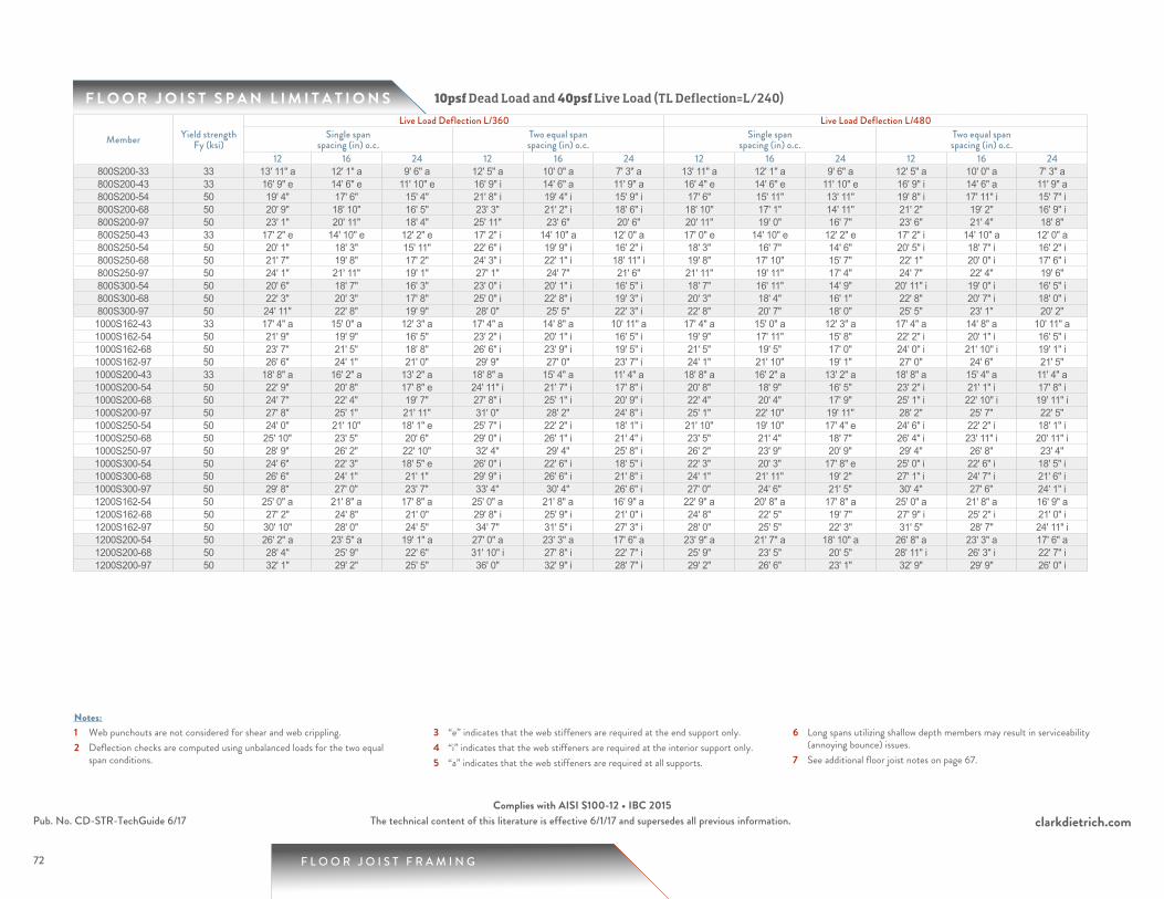
72
F L O O R J O I S T S P A N L I M I T A T I O N S
1 Web punchouts are not considered for shear and web crippling.2 Deflection checks are computed using unbalanced loads for the two equal
span conditions.
3 “e” indicates that the web stiffeners are required at the end support only.4 “i” indicates that the web stiffeners are required at the interior support only.5 “a” indicates that the web stiffeners are required at all supports.
6 Long spans utilizing shallow depth members may result in serviceability (annoying bounce) issues.
7 See additional floor joist notes on page 67.
Notes:
F L O O R J O I S T F R A M I N G
clarkdietrich.comPub. No. CD-STR-TechGuide 6/17 The technical content of this literature is effective 6/1/17 and supersedes all previous information.Complies with AISI S100-12 • IBC 2015
10psf Dead Load and 40psf Live Load (TL Deflection=L/240)
Member Yield strength Fy (ksi)
Live Load Deflection L/360 Live Load Deflection L/480Single span
spacing (in) o.c.Two equal spanspacing (in) o.c.
Single spanspacing (in) o.c.
Two equal spanspacing (in) o.c.
12 16 24 12 16 24 12 16 24 12 16 24800S200-33 33 13' 11" a 12' 1" a 9' 6" a 12' 5" a 10' 0" a 7' 3" a 13' 11" a 12' 1" a 9' 6" a 12' 5" a 10' 0" a 7' 3" a800S200-43 33 16' 9" e 14' 6" e 11' 10" e 16' 9" i 14' 6" a 11' 9" a 16' 4" e 14' 6" e 11' 10" e 16' 9" i 14' 6" a 11' 9" a800S200-54 50 19' 4" 17' 6" 15' 4" 21' 8" i 19' 4" i 15' 9" i 17' 6" 15' 11" 13' 11" 19' 8" i 17' 11" i 15' 7" i800S200-68 50 20' 9" 18' 10" 16' 5" 23' 3" 21' 2" i 18' 6" i 18' 10" 17' 1" 14' 11" 21' 2" 19' 2" 16' 9" i800S200-97 50 23' 1" 20' 11" 18' 4" 25' 11" 23' 6" 20' 6" 20' 11" 19' 0" 16' 7" 23' 6" 21' 4" 18' 8" 800S250-43 33 17' 2" e 14' 10" e 12' 2" e 17' 2" i 14' 10" a 12' 0" a 17' 0" e 14' 10" e 12' 2" e 17' 2" i 14' 10" a 12' 0" a800S250-54 50 20' 1" 18' 3" 15' 11" 22' 6" i 19' 9" i 16' 2" i 18' 3" 16' 7" 14' 6" 20' 5" i 18' 7" i 16' 2" i800S250-68 50 21' 7" 19' 8" 17' 2" 24' 3" i 22' 1" i 18' 11" i 19' 8" 17' 10" 15' 7" 22' 1" 20' 0" i 17' 6" i800S250-97 50 24' 1" 21' 11" 19' 1" 27' 1" 24' 7" 21' 6" 21' 11" 19' 11" 17' 4" 24' 7" 22' 4" 19' 6" 800S300-54 50 20' 6" 18' 7" 16' 3" 23' 0" i 20' 1" i 16' 5" i 18' 7" 16' 11" 14' 9" 20' 11" i 19' 0" i 16' 5" i800S300-68 50 22' 3" 20' 3" 17' 8" 25' 0" i 22' 8" i 19' 3" i 20' 3" 18' 4" 16' 1" 22' 8" 20' 7" i 18' 0" i800S300-97 50 24' 11" 22' 8" 19' 9" 28' 0" 25' 5" 22' 3" i 22' 8" 20' 7" 18' 0" 25' 5" 23' 1" 20' 2" 1000S162-43 33 17' 4" a 15' 0" a 12' 3" a 17' 4" a 14' 8" a 10' 11" a 17' 4" a 15' 0" a 12' 3" a 17' 4" a 14' 8" a 10' 11" a1000S162-54 50 21' 9" 19' 9" 16' 5" 23' 2" i 20' 1" i 16' 5" i 19' 9" 17' 11" 15' 8" 22' 2" i 20' 1" i 16' 5" i1000S162-68 50 23' 7" 21' 5" 18' 8" 26' 6" i 23' 9" i 19' 5" i 21' 5" 19' 5" 17' 0" 24' 0" i 21' 10" i 19' 1" i1000S162-97 50 26' 6" 24' 1" 21' 0" 29' 9" 27' 0" 23' 7" i 24' 1" 21' 10" 19' 1" 27' 0" 24' 6" 21' 5" 1000S200-43 33 18' 8" a 16' 2" a 13' 2" a 18' 8" a 15' 4" a 11' 4" a 18' 8" a 16' 2" a 13' 2" a 18' 8" a 15' 4" a 11' 4" a1000S200-54 50 22' 9" 20' 8" 17' 8" e 24' 11" i 21' 7" i 17' 8" i 20' 8" 18' 9" 16' 5" 23' 2" i 21' 1" i 17' 8" i1000S200-68 50 24' 7" 22' 4" 19' 7" 27' 8" i 25' 1" i 20' 9" i 22' 4" 20' 4" 17' 9" 25' 1" i 22' 10" i 19' 11" i1000S200-97 50 27' 8" 25' 1" 21' 11" 31' 0" 28' 2" 24' 8" i 25' 1" 22' 10" 19' 11" 28' 2" 25' 7" 22' 5" 1000S250-54 50 24' 0" 21' 10" 18' 1" e 25' 7" i 22' 2" i 18' 1" i 21' 10" 19' 10" 17' 4" e 24' 6" i 22' 2" i 18' 1" i1000S250-68 50 25' 10" 23' 5" 20' 6" 29' 0" i 26' 1" i 21' 4" i 23' 5" 21' 4" 18' 7" 26' 4" i 23' 11" i 20' 11" i1000S250-97 50 28' 9" 26' 2" 22' 10" 32' 4" 29' 4" 25' 8" i 26' 2" 23' 9" 20' 9" 29' 4" 26' 8" 23' 4" 1000S300-54 50 24' 6" 22' 3" 18' 5" e 26' 0" i 22' 6" i 18' 5" i 22' 3" 20' 3" 17' 8" e 25' 0" i 22' 6" i 18' 5" i1000S300-68 50 26' 6" 24' 1" 21' 1" 29' 9" i 26' 6" i 21' 8" i 24' 1" 21' 11" 19' 2" 27' 1" i 24' 7" i 21' 6" i1000S300-97 50 29' 8" 27' 0" 23' 7" 33' 4" 30' 4" 26' 6" i 27' 0" 24' 6" 21' 5" 30' 4" 27' 6" 24' 1" i1200S162-54 50 25' 0" a 21' 8" a 17' 8" a 25' 0" a 21' 8" a 16' 9" a 22' 9" a 20' 8" a 17' 8" a 25' 0" a 21' 8" a 16' 9" a1200S162-68 50 27' 2" 24' 8" 21' 0" 29' 8" i 25' 9" i 21' 0" i 24' 8" 22' 5" 19' 7" 27' 9" i 25' 2" i 21' 0" i1200S162-97 50 30' 10" 28' 0" 24' 5" 34' 7" 31' 5" i 27' 3" i 28' 0" 25' 5" 22' 3" 31' 5" 28' 7" 24' 11" i1200S200-54 50 26' 2" a 23' 5" a 19' 1" a 27' 0" a 23' 3" a 17' 6" a 23' 9" a 21' 7" a 18' 10" a 26' 8" a 23' 3" a 17' 6" a1200S200-68 50 28' 4" 25' 9" 22' 6" 31' 10" i 27' 8" i 22' 7" i 25' 9" 23' 5" 20' 5" 28' 11" i 26' 3" i 22' 7" i1200S200-97 50 32' 1" 29' 2" 25' 5" 36' 0" 32' 9" i 28' 7" i 29' 2" 26' 6" 23' 1" 32' 9" 29' 9" 26' 0" i
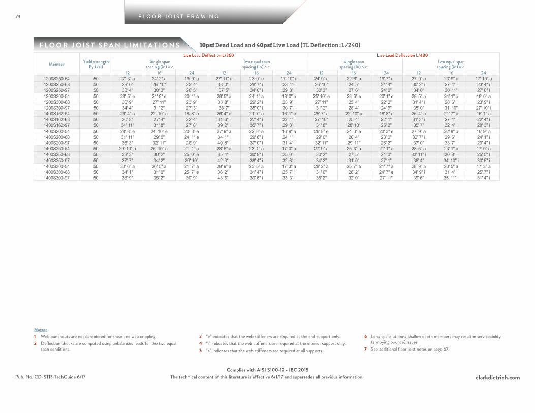
73
F L O O R J O I S T S P A N L I M I T A T I O N S
F L O O R J O I S T F R A M I N G
clarkdietrich.comPub. No. CD-STR-TechGuide 6/17 The technical content of this literature is effective 6/1/17 and supersedes all previous information.Complies with AISI S100-12 • IBC 2015
1 Web punchouts are not considered for shear and web crippling.2 Deflection checks are computed using unbalanced loads for the two equal
span conditions.
3 “e” indicates that the web stiffeners are required at the end support only.4 “i” indicates that the web stiffeners are required at the interior support only.5 “a” indicates that the web stiffeners are required at all supports.
6 Long spans utilizing shallow depth members may result in serviceability (annoying bounce) issues.
7 See additional floor joist notes on page 67.
Notes:
10psf Dead Load and 40psf Live Load (TL Deflection=L/240)
Member Yield strength Fy (ksi)
Live Load Deflection L/360 Live Load Deflection L/480Single span
spacing (in) o.c.Two equal spanspacing (in) o.c.
Single spanspacing (in) o.c.
Two equal spanspacing (in) o.c.
12 16 24 12 16 24 12 16 24 12 16 241200S250-54 50 27' 3" a 24' 2" a 19' 9" a 27' 11" a 23' 9" a 17' 10" a 24' 9" a 22' 6" a 19' 7" a 27' 9" a 23' 9" a 17' 10" a1200S250-68 50 29' 6" 26' 10" 23' 4" 33' 0" i 28' 7" i 23' 4" i 26' 10" 24' 5" 21' 4" 30' 2" i 27' 4" i 23' 4" i1200S250-97 50 33' 4" 30' 3" 26' 5" 37' 5" 34' 0" i 29' 8" i 30' 3" 27' 6" 24' 0" 34' 0" 30' 11" 27' 0" i1200S300-54 50 28' 5" e 24' 8" e 20' 1" e 28' 5" a 24' 1" a 18' 0" a 25' 10" e 23' 6" e 20' 1" e 28' 5" a 24' 1" a 18' 0" a1200S300-68 50 30' 9" 27' 11" 23' 9" 33' 8" i 29' 2" i 23' 9" i 27' 11" 25' 4" 22' 2" 31' 4" i 28' 6" i 23' 9" i1200S300-97 50 34' 4" 31' 2" 27' 3" 38' 7" 35' 0" i 30' 7" i 31' 2" 28' 4" 24' 9" 35' 0" 31' 10" 27' 10" i1400S162-54 50 26' 4" a 22' 10" a 18' 8" a 26' 4" a 21' 7" a 16' 1" a 25' 7" a 22' 10" a 18' 8" a 26' 4" a 21' 7" a 16' 1" a1400S162-68 50 30' 8" 27' 4" 22' 4" 31' 6" i 27' 4" i 22' 4" i 27' 10" 25' 4" 22' 1" 31' 3" i 27' 4" i 22' 4" i1400S162-97 50 34' 11" 31' 8" 27' 8" 39' 2" i 35' 7" i 29' 3" i 31' 8" 28' 10" 25' 2" 35' 7" 32' 4" i 28' 3" i1400S200-54 50 28' 8" e 24' 10" e 20' 3" e 27' 9" a 22' 8" a 16' 9" a 26' 8" e 24' 3" e 20' 3" e 27' 9" a 22' 8" a 16' 9" a1400S200-68 50 31' 11" 29' 0" 24' 1" e 34' 1" i 29' 6" i 24' 1" i 29' 0" 26' 4" 23' 0" 32' 7" i 29' 6" i 24' 1" i1400S200-97 50 36' 3" 32' 11" 28' 9" 40' 8" i 37' 0" i 31' 4" i 32' 11" 29' 11" 26' 2" 37' 0" 33' 7" i 29' 4" i1400S250-54 50 29' 10" a 25' 10" a 21' 1" a 28' 5" a 23' 1" a 17' 0" a 27' 9" a 25' 3" a 21' 1" a 28' 5" a 23' 1" a 17' 0" a1400S250-68 50 33' 3" 30' 2" 25' 0" e 35' 4" i 30' 8" i 25' 0" i 30' 2" 27' 5" 24' 0" 33' 11" i 30' 8" i 25' 0" i1400S250-97 50 37' 7" 34' 2" 29' 10" 42' 3" i 38' 4" i 32' 6" i 34' 2" 31' 0" 27' 1" 38' 4" 34' 10" i 30' 5" i1400S300-54 50 30' 6" a 26' 5" a 21' 7" a 28' 9" a 23' 5" a 17' 3" a 28' 2" a 25' 7" a 21' 7" a 28' 9" a 23' 5" a 17' 3" a1400S300-68 50 34' 1" 31' 0" 25' 7" e 36' 2" i 31' 4" i 25' 7" i 31' 0" 28' 2" 24' 7" e 34' 9" i 31' 4" i 25' 7" i1400S300-97 50 38' 9" 35' 2" 30' 9" 43' 6" i 39' 6" i 33' 3" i 35' 2" 32' 0" 27' 11" 39' 6" 35' 11" i 31' 4" i
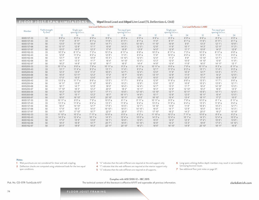
74
F L O O R J O I S T S P A N L I M I T A T I O N S
1 Web punchouts are not considered for shear and web crippling.2 Deflection checks are computed using unbalanced loads for the two equal
span conditions.
3 “e” indicates that the web stiffeners are required at the end support only.4 “i” indicates that the web stiffeners are required at the interior support only.5 “a” indicates that the web stiffeners are required at all supports.
6 Long spans utilizing shallow depth members may result in serviceability (annoying bounce) issues.
7 See additional floor joist notes on page 67.
Notes:
F L O O R J O I S T F R A M I N G
clarkdietrich.comPub. No. CD-STR-TechGuide 6/17 The technical content of this literature is effective 6/1/17 and supersedes all previous information.Complies with AISI S100-12 • IBC 2015
10psf Dead Load and 50psf Live Load (TL Deflection=L/240)
Member Yield strength Fy (ksi)
Live Load Deflection L/360 Live Load Deflection L/480Single span
spacing (in) o.c.Two equal spanspacing (in) o.c.
Single spanspacing (in) o.c.
Two equal spanspacing (in) o.c.
12 16 24 12 16 24 12 16 24 12 16 24600S137-33 33 9' 6" e 8' 3" e 6' 9" e 9' 6" a 8' 3" a 6' 5" a 9' 6" e 8' 3" e 6' 9" e 9' 6" a 8' 3" a 6' 5" a600S137-43 33 11' 6" 9' 11" 8' 1" e 11' 6" i 9' 11" i 8' 1" a 11' 0" 9' 11" 8' 1" e 11' 6" i 9' 11" i 8' 1" a600S137-54 50 13' 0" 11' 10" 10' 4" 14' 7" i 13' 3" i 10' 10" i 11' 10" 10' 9" 9' 5" 13' 3" 12' 1" i 10' 6" i600S137-68 50 13' 11" 12' 8" 11' 1" 15' 8" 14' 3" i 12' 5" i 12' 8" 11' 6" 10' 1" 14' 3" 12' 11" 11' 3" i600S137-97 50 15' 5" 14' 0" 12' 3" 17' 4" 15' 9" 13' 9" 14' 0" 12' 9" 11' 1" 15' 9" 14' 3" 12' 6" 600S162-33 33 10' 3" e 8' 11" e 7' 3" e 10' 3" a 8' 11" a 6' 8" a 10' 3" e 8' 11" e 7' 3" e 10' 3" a 8' 11" a 6' 8" a600S162-43 33 12' 8" 11' 0" e 9' 0" e 12' 8" i 11' 0" i 9' 0" a 11' 6" 10' 5" e 9' 0" e 12' 8" i 11' 0" i 9' 0" a600S162-54 50 13' 7" 12' 4" 10' 9" 15' 3" i 13' 10" i 12' 0" i 12' 4" 11' 2" 9' 9" 13' 10" 12' 7" i 11' 0" i600S162-68 50 14' 7" 13' 3" 11' 7" 16' 4" 14' 10" 13' 0" i 13' 3" 12' 0" 10' 6" 14' 10" 13' 6" 11' 9" i600S162-97 50 16' 2" 14' 8" 12' 10" 18' 1" 16' 5" 14' 4" 14' 8" 13' 4" 11' 8" 16' 5" 14' 11" 13' 1" 600S200-33 33 10' 11" e 9' 6" e 7' 9" e 10' 11" a 9' 3" a 6' 11" a 10' 11" e 9' 6" e 7' 9" e 10' 11" a 9' 3" a 6' 11" a600S200-43 33 13' 1" 11' 4" e 9' 3" e 13' 1" i 11' 4" i 9' 3" a 12' 1" 11' 0" e 9' 3" e 13' 1" i 11' 4" i 9' 3" a600S200-54 50 14' 3" 13' 0" 11' 4" 16' 0" i 14' 7" i 12' 4" i 13' 0" 11' 9" 10' 3" 14' 7" 13' 3" i 11' 7" i600S200-68 50 15' 4" 13' 11" 12' 2" 17' 2" 15' 7" 13' 8" i 13' 11" 12' 8" 11' 0" 15' 7" 14' 2" 12' 5" i600S200-97 50 17' 0" 15' 5" 13' 6" 19' 1" 17' 4" 15' 2" 15' 5" 14' 0" 12' 3" 17' 4" 15' 9" 13' 9" 600S250-43 33 13' 5" e 11' 7" e 9' 6" e 13' 5" i 11' 7" i 9' 6" a 12' 8" 11' 6" e 9' 6" e 13' 5" i 11' 7" i 9' 6" a600S250-54 50 14' 11" 13' 6" 11' 10" 16' 8" i 15' 2" i 12' 8" i 13' 6" 12' 3" 10' 9" 15' 2" i 13' 9" i 12' 1" i600S250-68 50 16' 1" 14' 7" 12' 9" 18' 0" 16' 4" i 14' 4" i 14' 7" 13' 3" 11' 7" 16' 4" 14' 10" 13' 0" i600S250-97 50 17' 10" 16' 3" 14' 2" 20' 0" 18' 2" 15' 11" 16' 3" 14' 9" 12' 10" 18' 2" 16' 6" 14' 5" 600S300-54 50 15' 2" 13' 10" 12' 1" 17' 1" i 15' 6" i 12' 10" i 13' 10" 12' 7" 10' 11" 15' 6" i 14' 1" i 12' 4" i600S300-68 50 16' 7" 15' 1" 13' 2" 18' 7" 16' 11" i 14' 9" i 15' 1" 13' 8" 12' 0" 16' 11" 15' 4" 13' 5" i600S300-97 50 18' 6" 16' 10" 14' 9" 20' 10" 18' 11" 16' 6" 16' 10" 15' 4" 13' 4" 18' 11" 17' 2" 15' 0" 800S137-33 33 10' 11" a 9' 5" a 7' 9" a 10' 0" a 8' 1" a 5' 11" a 10' 11" a 9' 5" a 7' 9" a 10' 0" a 8' 1" a 5' 11" a800S137-43 33 13' 3" e 11' 6" e 9' 4" e 13' 3" i 11' 6" a 9' 4" a 13' 3" e 11' 6" e 9' 4" e 13' 3" i 11' 6" a 9' 4" a800S137-54 50 16' 4" 14' 10" 12' 7" 17' 9" i 15' 5" i 12' 7" i 14' 10" 13' 6" 11' 9" 16' 8" i 15' 2" i 12' 7" i800S137-68 50 17' 8" 16' 0" 14' 0" 19' 10" i 18' 0" i 14' 10" i 16' 0" 14' 7" 12' 9" 18' 0" 16' 4" i 14' 3" i800S137-97 50 19' 7" 17' 10" 15' 7" 22' 0" 20' 0" 17' 5" i 17' 10" 16' 2" 14' 2" 20' 0" 18' 2" 15' 10" 800S162-33 33 11' 10" a 10' 3" a 7' 11" a 10' 6" a 8' 5" a 6' 2" a 11' 10" a 10' 3" a 7' 11" a 10' 6" a 8' 5" a 6' 2" a800S162-43 33 14' 3" e 12' 4" e 10' 1" e 14' 3" i 12' 4" a 10' 0" a 14' 3" e 12' 4" e 10' 1" e 14' 3" i 12' 4" a 10' 0" a800S162-54 50 17' 0" 15' 5" 13' 6" 19' 1" i 16' 6" i 13' 6" i 15' 5" 14' 0" 12' 3" 17' 4" i 15' 9" i 13' 6" i800S162-68 50 18' 4" 16' 8" 14' 7" 20' 7" i 18' 9" i 15' 10" i 16' 8" 15' 2" 13' 3" 18' 9" 17' 0" i 14' 10" i800S162-97 50 20' 5" 18' 6" 16' 2" 22' 11" 20' 10" 18' 2" i 18' 6" 16' 10" 14' 9" 20' 10" 18' 11" 16' 6"
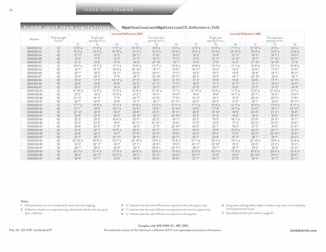
75
F L O O R J O I S T S P A N L I M I T A T I O N S
F L O O R J O I S T F R A M I N G
clarkdietrich.comPub. No. CD-STR-TechGuide 6/17 The technical content of this literature is effective 6/1/17 and supersedes all previous information.Complies with AISI S100-12 • IBC 2015
1 Web punchouts are not considered for shear and web crippling.2 Deflection checks are computed using unbalanced loads for the two equal
span conditions.
3 “e” indicates that the web stiffeners are required at the end support only.4 “i” indicates that the web stiffeners are required at the interior support only.5 “a” indicates that the web stiffeners are required at all supports.
6 Long spans utilizing shallow depth members may result in serviceability (annoying bounce) issues.
7 See additional floor joist notes on page 67.
Notes:
10psf Dead Load and 50psf Live Load (TL Deflection=L/240)
Member Yield strength Fy (ksi)
Live Load Deflection L/360 Live Load Deflection L/480Single span
spacing (in) o.c.Two equal spanspacing (in) o.c.
Single spanspacing (in) o.c.
Two equal spanspacing (in) o.c.
12 16 24 12 16 24 12 16 24 12 16 24800S200-33 33 12' 8" a 11' 0" a 7' 11" a 10' 10" a 8' 9" a 6' 4" a 12' 8" a 11' 0" a 7' 11" a 10' 10" a 8' 9" a 6' 4" a800S200-43 33 15' 3" e 13' 3" e 10' 10" e 15' 3" a 13' 3" a 10' 5" a 15' 2" e 13' 3" e 10' 10" e 15' 3" a 13' 3" a 10' 5" a800S200-54 50 17' 11" 16' 3" 14' 3" 20' 1" i 17' 8" i 14' 5" i 16' 3" 14' 9" 12' 11" 18' 3" i 16' 7" i 14' 5" i800S200-68 50 19' 3" 17' 6" 15' 3" 21' 7" i 19' 7" i 17' 2" i 17' 6" 15' 11" 13' 10" 19' 7" 17' 10" i 15' 7" i800S200-97 50 21' 5" 19' 5" 17' 0" 24' 0" 21' 10" 19' 1" 19' 5" 17' 8" 15' 5" 21' 10" 19' 10" 17' 4" 800S250-43 33 15' 8" e 13' 7" e 11' 1" e 15' 8" a 13' 7" a 10' 6" a 15' 8" e 13' 7" e 11' 1" e 15' 8" a 13' 7" a 10' 6" a800S250-54 50 18' 7" 16' 11" 14' 9" e 20' 10" i 18' 1" i 14' 9" i 16' 11" 15' 4" 13' 5" 19' 0" i 17' 3" i 14' 9" i800S250-68 50 20' 1" 18' 3" 15' 11" 22' 6" i 20' 6" i 17' 3" i 18' 3" 16' 7" 14' 6" 20' 6" 18' 7" i 16' 3" i800S250-97 50 22' 4" 20' 4" 17' 9" 25' 1" 22' 10" 19' 11" i 20' 4" 18' 5" 16' 1" 22' 10" 20' 9" 18' 1" 800S300-54 50 19' 0" 17' 3" 14' 11" e 21' 2" i 18' 4" i 14' 11" i 17' 3" 15' 8" 13' 9" 19' 5" i 17' 7" i 14' 11" i800S300-68 50 20' 8" 18' 9" 16' 5" 23' 2" i 21' 1" i 17' 7" i 18' 9" 17' 1" 14' 11" 21' 1" 19' 2" i 16' 9" i800S300-97 50 23' 2" 21' 0" 18' 4" 26' 0" 23' 7" 20' 7" i 21' 0" 19' 1" 16' 8" 23' 7" 21' 5" 18' 9" 1000S162-43 33 15' 10" a 13' 8" a 11' 2" a 15' 9" a 12' 10" a 9' 7" a 15' 10" a 13' 8" a 11' 2" a 15' 9" a 12' 10" a 9' 7" a1000S162-54 50 20' 2" 18' 4" 15' 0" e 21' 2" i 18' 4" i 15' 0" i 18' 4" 16' 8" 14' 7" e 20' 7" i 18' 4" i 15' 0" i1000S162-68 50 21' 11" 19' 11" 17' 4" 24' 7" i 21' 8" i 17' 8" i 19' 11" 18' 1" 15' 9" 22' 4" i 20' 3" i 17' 8" i1000S162-97 50 24' 7" 22' 4" 19' 6" 27' 7" 25' 1" 21' 11" i 22' 4" 20' 3" 17' 9" 25' 1" 22' 9" 19' 11" i1000S200-43 33 17' 1" a 14' 9" a 12' 1" a 16' 6" a 13' 5" a 9' 11" a 17' 1" a 14' 9" a 12' 1" a 16' 6" a 13' 5" a 9' 11" a1000S200-54 50 21' 1" 19' 2" 16' 1" e 22' 9" i 19' 9" i 15' 10" i 19' 2" 17' 5" 15' 3" e 21' 6" i 19' 7" i 15' 10" i1000S200-68 50 22' 10" 20' 9" 18' 2" 25' 8" i 23' 2" i 18' 11" i 20' 9" 18' 10" 16' 6" 23' 4" i 21' 2" i 18' 6" i1000S200-97 50 25' 8" 23' 4" 20' 4" 28' 10" 26' 2" 22' 10" i 23' 4" 21' 2" 18' 6" 26' 2" 23' 9" 20' 9" i1000S250-54 50 22' 3" 20' 3" 16' 6" e 23' 5" i 20' 3" i 16' 1" i 20' 3" 18' 5" 16' 1" e 22' 9" i 20' 3" i 16' 1" i1000S250-68 50 24' 0" 21' 9" 19' 0" 26' 11" i 23' 10" i 19' 6" i 21' 9" 19' 9" 17' 3" 24' 5" i 22' 3" i 19' 5" i1000S250-97 50 26' 9" 24' 3" 21' 3" 30' 0" 27' 3" 23' 10" i 24' 3" 22' 1" 19' 3" 27' 3" 24' 9" 21' 8" i1000S300-54 50 22' 9" 20' 7" 16' 9" e 23' 9" i 20' 7" i 16' 3" i 20' 8" 18' 9" 16' 5" e 23' 2" i 20' 7" i 16' 3" i1000S300-68 50 24' 8" 22' 5" 19' 7" 27' 8" i 24' 3" i 19' 9" i 22' 5" 20' 4" 17' 9" 25' 2" i 22' 10" i 19' 9" i1000S300-97 50 27' 7" 25' 1" 21' 11" 30' 11" 28' 1" i 24' 7" i 25' 1" 22' 9" 19' 11" 28' 1" 25' 7" 22' 4" i1200S162-54 50 22' 10" a 19' 9" a 16' 1" a 22' 10" a 19' 6" a 14' 8" a 21' 1" a 19' 2" a 16' 1" a 22' 10" a 19' 6" a 14' 8" a1200S162-68 50 25' 3" 22' 11" 19' 2" 27' 1" i 23' 6" i 19' 2" i 22' 11" 20' 10" 18' 2" 25' 9" i 23' 5" i 19' 2" i1200S162-97 50 28' 7" 26' 0" 22' 8" 32' 1" 29' 2" i 24' 11" i 26' 0" 23' 7" 20' 7" 29' 2" 26' 6" 23' 2" i1200S200-54 50 24' 3" a 21' 4" a 17' 5" a 24' 8" a 20' 6" a 15' 4" a 22' 0" a 20' 0" a 17' 5" a 24' 8" a 20' 6" a 15' 4" a1200S200-68 50 26' 4" 23' 11" 20' 8" e 29' 2" i 25' 3" i 20' 8" i 23' 11" 21' 9" 19' 0" 26' 10" i 24' 5" i 20' 8" i1200S200-97 50 29' 9" 27' 1" 23' 8" 33' 5" 30' 4" i 26' 6" i 27' 1" 24' 7" 21' 6" 30' 4" 27' 7" 24' 1" i

76
F L O O R J O I S T S P A N L I M I T A T I O N S
1 Web punchouts are not considered for shear and web crippling.2 Deflection checks are computed using unbalanced loads for the two equal
span conditions.
3 “e” indicates that the web stiffeners are required at the end support only.4 “i” indicates that the web stiffeners are required at the interior support only.5 “a” indicates that the web stiffeners are required at all supports.
6 Long spans utilizing shallow depth members may result in serviceability (annoying bounce) issues.
7 See additional floor joist notes on page 67.
Notes:
F L O O R J O I S T F R A M I N G
clarkdietrich.comPub. No. CD-STR-TechGuide 6/17 The technical content of this literature is effective 6/1/17 and supersedes all previous information.Complies with AISI S100-12 • IBC 2015
10psf Dead Load and 50psf Live Load (TL Deflection=L/240)
Member Yield strength Fy (ksi)
Live Load Deflection L/360 Live Load Deflection L/480Single span
spacing (in) o.c.Two equal spanspacing (in) o.c.
Single spanspacing (in) o.c.
Two equal spanspacing (in) o.c.
12 16 24 12 16 24 12 16 24 12 16 241200S250-54 50 25' 3" a 22' 1" a 18' 0" a 25' 6" a 20' 11" a 15' 7" a 22' 11" a 20' 10" a 18' 0" a 25' 6" a 20' 11" a 15' 7" a1200S250-68 50 27' 5" 24' 11" 21' 4" e 30' 1" i 26' 1" i 21' 4" i 24' 11" 22' 8" 19' 9" 28' 0" i 25' 5" i 21' 4" i1200S250-97 50 30' 11" 28' 1" 24' 7" 34' 9" 31' 7" i 27' 5" i 28' 1" 25' 6" 22' 4" 31' 7" 28' 8" 25' 0" i1200S300-54 50 26' 0" a 22' 6" a 18' 4" a 25' 10" a 21' 2" a 15' 9" a 24' 0" a 21' 9" a 18' 4" a 25' 10" a 21' 2" a 15' 9" a1200S300-68 50 28' 6" 25' 11" 21' 9" e 30' 8" i 26' 7" i 21' 9" i 25' 11" 23' 6" 20' 7" 29' 1" i 26' 5" i 21' 9" i1200S300-97 50 31' 11" 29' 0" 25' 4" 35' 10" i 32' 6" i 28' 0" i 29' 0" 26' 4" 23' 0" 32' 6" 29' 7" i 25' 10" i1400S162-54 50 24' 1" a 20' 10" a 17' 0" a 23' 2" a 18' 11" a 14' 0" a 23' 9" a 20' 10" a 17' 0" a 23' 2" a 18' 11" a 14' 0" a1400S162-68 50 28' 6" 24' 11" 20' 4" e 28' 10" i 24' 11" i 20' 4" i 25' 10" 23' 6" 20' 4" e 28' 10" i 24' 11" i 20' 4" i1400S162-97 50 32' 5" 29' 5" 25' 9" 36' 4" i 32' 8" i 26' 8" i 29' 5" 26' 9" 23' 4" 33' 1" 30' 0" i 26' 3" i1400S200-54 50 26' 2" a 22' 8" a 18' 6" a 24' 5" a 19' 10" a 14' 7" a 24' 9" a 22' 6" a 18' 6" a 24' 5" a 19' 10" a 14' 7" a1400S200-68 50 29' 8" 26' 11" 22' 0" e 31' 1" i 26' 11" i 22' 0" i 26' 11" 24' 6" 21' 5" e 30' 3" i 26' 11" i 22' 0" i1400S200-97 50 33' 8" 30' 7" 26' 9" 37' 9" i 34' 4" i 28' 7" i 30' 7" 27' 9" 24' 3" 34' 4" 31' 2" i 27' 3" i1400S250-54 50 27' 2" a 23' 7" a 19' 3" a 24' 11" a 20' 2" a 14' 10" a 25' 9" a 23' 5" a 19' 3" a 24' 11" a 20' 2" a 14' 10" a1400S250-68 50 30' 10" 28' 0" 22' 10" e 32' 3" i 28' 0" i 22' 6" i 28' 0" 25' 6" 22' 3" e 31' 6" i 28' 0" i 22' 6" i1400S250-97 50 34' 11" 31' 9" 27' 8" 39' 2" i 35' 7" i 29' 8" i 31' 9" 28' 10" 25' 2" 35' 7" 32' 4" i 28' 3" i1400S300-54 50 27' 10" a 24' 2" a 19' 7" a 25' 3" a 20' 5" a 14' 11" a 26' 2" a 23' 9" a 19' 7" a 25' 3" a 20' 5" a 14' 11" a1400S300-68 50 31' 8" 28' 7" 23' 4" e 33' 1" i 28' 7" i 22' 10" i 28' 9" 26' 2" 22' 10" e 32' 4" i 28' 7" i 22' 10" i1400S300-97 50 36' 0" 32' 8" 28' 7" 40' 5" i 36' 8" i 30' 4" i 32' 8" 29' 8" 25' 11" 36' 8" 33' 4" i 29' 1" i

77
F L O O R J O I S T S P A N L I M I T A T I O N S
F L O O R J O I S T F R A M I N G
clarkdietrich.comPub. No. CD-STR-TechGuide 6/17 The technical content of this literature is effective 6/1/17 and supersedes all previous information.Complies with AISI S100-12 • IBC 2015
1 Web punchouts are not considered for shear and web crippling.2 Deflection checks are computed using unbalanced loads for the two equal
span conditions.
3 “e” indicates that the web stiffeners are required at the end support only.4 “i” indicates that the web stiffeners are required at the interior support only.5 “a” indicates that the web stiffeners are required at all supports.
6 Long spans utilizing shallow depth members may result in serviceability (annoying bounce) issues.
7 See additional floor joist notes on page 67.
Notes:
10psf Dead Load and 100psf Live Load (TL Deflection=L/240)
Member Yield strength Fy (ksi)
Live Load Deflection L/360 Live Load Deflection L/480Single span
spacing (in) o.c.Two equal spanspacing (in) o.c.
Single spanspacing (in) o.c.
Two equal spanspacing (in) o.c.
12 16 24 12 16 24 12 16 24 12 16 24600S137-33 33 7' 1" e 6' 1" e 5' 0" e 6' 10" a 5' 7" a 4' 1" a 7' 1" e 6' 1" e 5' 0" e 6' 10" a 5' 7" a 4' 1" a600S137-43 33 8' 6" e 7' 4" e 6' 0" e 8' 6" a 7' 4" a 6' 0" a 8' 6" e 7' 4" e 6' 0" e 8' 6" a 7' 4" a 6' 0" a600S137-54 50 10' 4" 9' 5" 8' 0" 11' 4" i 9' 10" i 8' 0" i 9' 5" 8' 6" 7' 5" 10' 6" i 9' 7" i 8' 0" i600S137-68 50 11' 1" 10' 1" 8' 9" 12' 5" i 11' 3" i 9' 4" i 10' 1" 9' 2" 8' 0" 11' 3" 10' 3" i 8' 11" i600S137-97 50 12' 3" 11' 1" 9' 9" 13' 9" 12' 6" 10' 11" i 11' 1" 10' 1" 8' 10" 12' 6" 11' 4" 9' 11" 600S162-33 33 7' 7" e 6' 7" e 5' 4" e 7' 1" a 5' 9" a 4' 3" a 7' 7" e 6' 7" e 5' 4" e 7' 1" a 5' 9" a 4' 3" a600S162-43 33 9' 4" e 8' 1" e 6' 7" e 9' 4" a 8' 1" a 6' 7" a 9' 1" e 8' 1" e 6' 7" e 9' 4" a 8' 1" a 6' 7" a600S162-54 50 10' 9" 9' 9" 8' 7" e 12' 1" i 10' 10" i 8' 10" i 9' 9" 8' 11" 7' 9" 11' 0" i 10' 0" i 8' 9" i600S162-68 50 11' 7" 10' 6" 9' 2" 13' 0" i 11' 9" i 10' 4" i 10' 6" 9' 6" 8' 4" 11' 9" 10' 8" i 9' 4" i600S162-97 50 12' 10" 11' 8" 10' 2" 14' 4" 13' 1" 11' 5" i 11' 8" 10' 7" 9' 3" 13' 1" 11' 10" 10' 4" 600S200-33 33 8' 1" e 7' 0" e 5' 9" e 7' 4" a 6' 0" a 4' 4" a 8' 1" e 7' 0" e 5' 9" e 7' 4" a 6' 0" a 4' 4" a600S200-43 33 9' 8" e 8' 4" e 6' 10" e 9' 8" a 8' 4" a 6' 10" a 9' 7" e 8' 4" e 6' 10" e 9' 8" a 8' 4" a 6' 10" a600S200-54 50 11' 4" 10' 3" 9' 0" e 12' 9" i 11' 2" i 9' 1" i 10' 3" 9' 4" 8' 2" 11' 7" i 10' 6" i 9' 1" i600S200-68 50 12' 2" 11' 0" 9' 8" 13' 8" i 12' 5" i 10' 10" i 11' 0" 10' 0" 8' 9" 12' 5" 11' 3" i 9' 10" i600S200-97 50 13' 6" 12' 3" 10' 8" 15' 2" 13' 9" 12' 0" i 12' 3" 11' 2" 9' 9" 13' 9" 12' 6" 10' 11" 600S250-43 33 9' 11" e 8' 7" e 7' 0" e 9' 11" a 8' 7" a 7' 0" a 9' 11" e 8' 7" e 7' 0" e 9' 11" a 8' 7" a 7' 0" a600S250-54 50 11' 10" 10' 9" 9' 4" e 13' 2" i 11' 5" i 9' 4" i 10' 9" 9' 9" 8' 6" e 12' 1" i 10' 11" i 9' 4" i600S250-68 50 12' 9" 11' 7" 10' 1" 14' 4" i 13' 0" i 10' 11" i 11' 7" 10' 6" 9' 2" 13' 0" i 11' 10" i 10' 4" i600S250-97 50 14' 2" 12' 10" 11' 3" 15' 11" 14' 5" 12' 7" i 12' 10" 11' 8" 10' 3" 14' 5" 13' 1" 11' 6" 600S300-54 50 12' 1" 10' 11" 9' 6" e 13' 5" i 11' 7" i 9' 6" i 10' 11" 9' 11" 8' 8" e 12' 4" i 11' 2" i 9' 6" i600S300-68 50 13' 2" 12' 0" 10' 5" 14' 9" i 13' 5" i 11' 1" i 12' 0" 10' 10" 9' 6" 13' 5" i 12' 2" i 10' 8" i600S300-97 50 14' 9" 13' 4" 11' 8" 16' 6" 15' 0" 13' 1" i 13' 4" 12' 2" 10' 7" 15' 0" 13' 8" 11' 11" i800S137-33 33 8' 1" a 6' 6" a 4' 4" a 6' 4" a 5' 1" a 3' 5" a 8' 1" a 6' 6" a 4' 4" a 6' 4" a 5' 1" a 3' 5" a800S137-43 33 9' 9" e 8' 6" e 6' 11" e 9' 9" a 8' 3" a 6' 2" a 9' 9" e 8' 6" e 6' 11" e 9' 9" a 8' 3" a 6' 2" a800S137-54 50 12' 11" 11' 5" 9' 3" e 13' 2" i 11' 5" i 9' 3" a 11' 9" 10' 8" 9' 3" e 13' 2" i 11' 5" i 9' 3" a800S137-68 50 14' 0" 12' 9" 10' 11" 15' 6" i 13' 5" i 10' 11" i 12' 9" 11' 7" 10' 1" 14' 3" i 13' 0" i 10' 11" i800S137-97 50 15' 7" 14' 2" 12' 4" 17' 5" 15' 10" i 13' 10" i 14' 2" 12' 10" 11' 3" 15' 10" 14' 5" 12' 7" i800S162-33 33 8' 7" a 6' 6" a 4' 4" a 6' 7" a 5' 2" a 3' 5" a 8' 7" a 6' 6" a 4' 4" a 6' 7" a 5' 2" a 3' 5" a800S162-43 33 10' 7" e 9' 2" e 7' 5" e 10' 7" a 8' 8" a 6' 5" a 10' 7" e 9' 2" e 7' 5" e 10' 7" a 8' 8" a 6' 5" a800S162-54 50 13' 6" 12' 3" e 10' 0" e 14' 1" i 12' 3" i 10' 0" a 12' 3" 11' 1" 9' 9" e 13' 9" i 12' 3" i 10' 0" a800S162-68 50 14' 7" 13' 3" 11' 7" 16' 4" i 14' 4" i 11' 8" i 13' 3" 12' 0" 10' 6" 14' 10" i 13' 6" i 11' 8" i800S162-97 50 16' 2" 14' 9" 12' 10" 18' 2" 16' 6" i 14' 5" i 14' 9" 13' 4" 11' 8" 16' 6" 15' 0" 13' 1" i

78
F L O O R J O I S T S P A N L I M I T A T I O N S
1 Web punchouts are not considered for shear and web crippling.2 Deflection checks are computed using unbalanced loads for the two equal
span conditions.
3 “e” indicates that the web stiffeners are required at the end support only.4 “i” indicates that the web stiffeners are required at the interior support only.5 “a” indicates that the web stiffeners are required at all supports.
6 Long spans utilizing shallow depth members may result in serviceability (annoying bounce) issues.
7 See additional floor joist notes on page 67.
Notes:
F L O O R J O I S T F R A M I N G
clarkdietrich.comPub. No. CD-STR-TechGuide 6/17 The technical content of this literature is effective 6/1/17 and supersedes all previous information.Complies with AISI S100-12 • IBC 2015
10psf Dead Load and 100psf Live Load (TL Deflection=L/240)
Member Yield strength Fy (ksi)
Live Load Deflection L/360 Live Load Deflection L/480Single span
spacing (in) o.c.Two equal spanspacing (in) o.c.
Single spanspacing (in) o.c.
Two equal spanspacing (in) o.c.
12 16 24 12 16 24 12 16 24 12 16 24800S200-33 33 8' 7" a 6' 6" a 4' 4" a 6' 9" a 5' 2" a 3' 5" a 8' 7" a 6' 6" a 4' 4" a 6' 9" a 5' 2" a 3' 5" a800S200-43 33 11' 3" e 9' 9" e 8' 0" e 11' 0" a 9' 0" a 6' 8" a 11' 3" e 9' 9" e 8' 0" e 11' 0" a 9' 0" a 6' 8" a800S200-54 50 14' 3" 12' 11" e 10' 8" e 15' 1" i 13' 0" i 10' 8" a 12' 11" 11' 9" 10' 3" e 14' 6" i 13' 0" i 10' 8" a800S200-68 50 15' 3" 13' 10" 12' 1" e 17' 2" i 15' 7" i 12' 11" i 13' 10" 12' 7" 11' 0" 15' 7" i 14' 2" i 12' 4" i800S200-97 50 17' 0" 15' 5" 13' 6" 19' 1" 17' 4" i 15' 2" i 15' 5" 14' 0" 12' 3" 17' 4" 15' 9" 13' 9" i800S250-43 33 11' 7" e 10' 0" e 8' 2" e 11' 2" a 9' 2" a 6' 9" a 11' 7" e 10' 0" e 8' 2" e 11' 2" a 9' 2" a 6' 9" a800S250-54 50 14' 9" 13' 4" e 10' 11" e 15' 5" i 13' 4" i 10' 9" a 13' 5" 12' 2" e 10' 8" e 15' 1" i 13' 4" i 10' 9" a800S250-68 50 15' 11" 14' 6" 12' 8" e 17' 11" i 15' 8" i 12' 9" i 14' 6" 13' 2" 11' 6" 16' 3" i 14' 9" i 12' 9" i800S250-97 50 17' 9" 16' 1" 14' 1" 19' 11" 18' 1" i 15' 10" i 16' 1" 14' 8" 12' 10" 18' 1" 16' 5" 14' 4" i800S300-54 50 15' 1" 13' 6" e 11' 1" e 15' 7" i 13' 6" i 10' 11" a 13' 9" 12' 5" e 10' 11" e 15' 5" i 13' 6" i 10' 11" a800S300-68 50 16' 5" 14' 11" 13' 0" e 18' 4" i 15' 11" i 13' 0" i 14' 11" 13' 6" 11' 10" 16' 9" i 15' 2" i 13' 0" i800S300-97 50 18' 4" 16' 8" 14' 7" 20' 7" i 18' 9" i 16' 4" i 16' 8" 15' 2" 13' 3" 18' 9" 17' 0" 14' 10" i1000S162-43 33 11' 8" a 10' 1" a 7' 7" a 10' 2" a 8' 2" a 5' 11" a 11' 8" a 10' 1" a 7' 7" a 10' 2" a 8' 2" a 5' 11" a1000S162-54 50 15' 8" e 13' 7" e 11' 1" e 15' 8" i 13' 2" i 9' 11" a 14' 7" 13' 3" e 11' 1" e 15' 8" i 13' 2" i 9' 11" a1000S162-68 50 17' 4" 15' 9" 13' 1" e 18' 6" i 16' 0" i 13' 1" i 15' 9" 14' 4" 12' 6" e 17' 9" i 16' 0" i 13' 1" i1000S162-97 50 19' 6" 17' 9" 15' 6" 21' 11" i 19' 11" i 16' 9" i 17' 9" 16' 1" 14' 1" 19' 11" 18' 1" i 15' 9" i1000S200-43 33 12' 7" a 10' 11" a 7' 7" a 10' 7" a 8' 6" a 6' 1" a 12' 7" a 10' 11" a 7' 7" a 10' 7" a 8' 6" a 6' 1" a1000S200-54 50 16' 9" e 14' 7" e 11' 11" e 16' 10" i 13' 9" a 10' 3" a 15' 3" 13' 10" e 11' 11" e 16' 10" i 13' 9" a 10' 3" a1000S200-68 50 18' 2" 16' 6" 14' 0" e 19' 9" i 17' 2" i 14' 0" a 16' 6" 15' 0" 13' 1" e 18' 6" i 16' 10" i 14' 0" a1000S200-97 50 20' 4" 18' 6" 16' 2" 22' 10" i 20' 9" i 17' 10" i 18' 6" 16' 10" 14' 8" 20' 9" 18' 11" i 16' 6" i1000S250-54 50 17' 3" e 14' 11" e 12' 3" e 17' 1" i 14' 0" a 10' 5" a 16' 1" e 14' 7" e 12' 3" e 17' 1" i 14' 0" a 10' 5" a1000S250-68 50 19' 0" 17' 3" 14' 4" e 20' 4" i 17' 7" i 14' 4" a 17' 3" 15' 8" 13' 9" e 19' 5" i 17' 7" i 14' 4" a1000S250-97 50 21' 3" 19' 3" 16' 10" 23' 10" i 21' 8" i 18' 11" i 19' 3" 17' 6" 15' 4" 21' 8" 19' 8" i 17' 2" i1000S300-54 50 17' 6" e 15' 2" e 12' 5" e 17' 3" i 14' 1" a 10' 6" a 16' 5" e 14' 11" e 12' 5" e 17' 3" i 14' 1" a 10' 6" a1000S300-68 50 19' 7" 17' 9" e 14' 7" e 20' 8" i 17' 11" i 14' 7" a 17' 9" 16' 2" 14' 1" e 19' 11" i 17' 11" i 14' 7" a1000S300-97 50 21' 11" 19' 11" 17' 4" 24' 7" i 22' 4" i 18' 9" i 19' 11" 18' 1" 15' 9" 22' 4" 20' 3" i 17' 9" i1200S162-54 50 16' 10" a 14' 7" a 11' 11" a 15' 8" a 12' 8" a 9' 4" a 16' 9" a 14' 7" a 11' 11" a 15' 8" a 12' 8" a 9' 4" a1200S162-68 50 20' 0" 17' 4" e 14' 2" e 20' 0" i 17' 4" i 14' 1" a 18' 2" 16' 6" 14' 2" e 20' 0" i 17' 4" i 14' 1" a1200S162-97 50 22' 8" 20' 7" 18' 0" 25' 6" i 22' 6" i 18' 4" i 20' 7" 18' 9" 16' 4" 23' 2" i 21' 0" i 18' 4" i1200S200-54 50 18' 3" a 15' 9" a 12' 6" a 16' 4" a 13' 2" a 9' 8" a 17' 6" a 15' 9" a 12' 6" a 16' 4" a 13' 2" a 9' 8" a1200S200-68 50 20' 11" 18' 8" e 15' 3" e 21' 7" i 18' 8" i 14' 9" a 19' 0" 17' 3" e 15' 1" e 21' 4" i 18' 8" i 14' 9" a1200S200-97 50 23' 8" 21' 6" 18' 9" 26' 6" i 24' 0" i 19' 7" i 21' 6" 19' 6" 17' 0" 24' 1" i 21' 11" i 19' 2" i
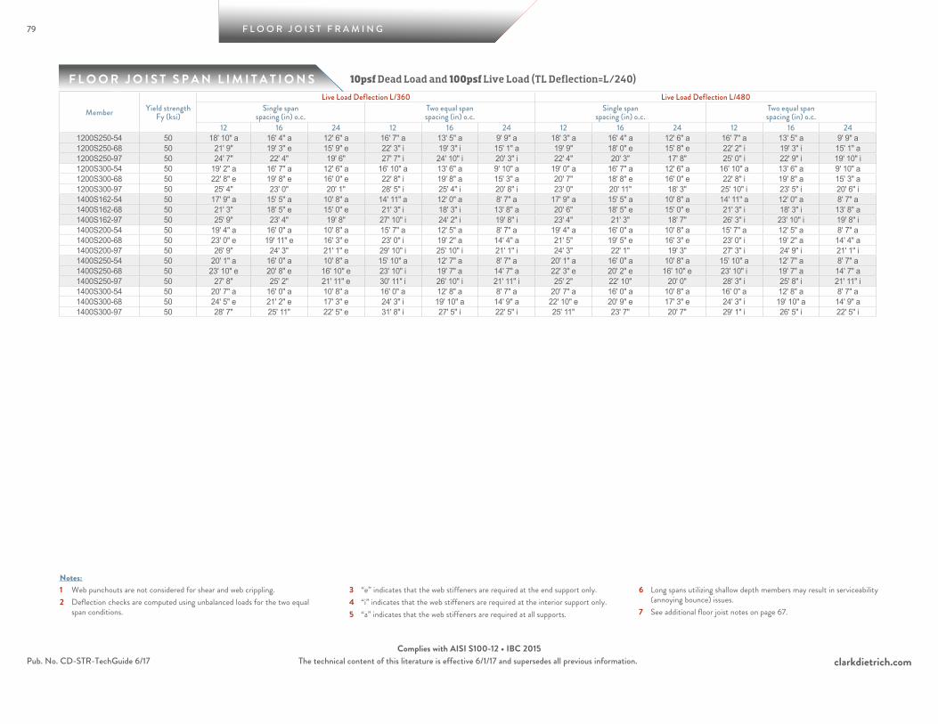
79
F L O O R J O I S T S P A N L I M I T A T I O N S
F L O O R J O I S T F R A M I N G
clarkdietrich.comPub. No. CD-STR-TechGuide 6/17 The technical content of this literature is effective 6/1/17 and supersedes all previous information.Complies with AISI S100-12 • IBC 2015
1 Web punchouts are not considered for shear and web crippling.2 Deflection checks are computed using unbalanced loads for the two equal
span conditions.
3 “e” indicates that the web stiffeners are required at the end support only.4 “i” indicates that the web stiffeners are required at the interior support only.5 “a” indicates that the web stiffeners are required at all supports.
6 Long spans utilizing shallow depth members may result in serviceability (annoying bounce) issues.
7 See additional floor joist notes on page 67.
Notes:
10psf Dead Load and 100psf Live Load (TL Deflection=L/240)
Member Yield strength Fy (ksi)
Live Load Deflection L/360 Live Load Deflection L/480Single span
spacing (in) o.c.Two equal spanspacing (in) o.c.
Single spanspacing (in) o.c.
Two equal spanspacing (in) o.c.
12 16 24 12 16 24 12 16 24 12 16 241200S250-54 50 18' 10" a 16' 4" a 12' 6" a 16' 7" a 13' 5" a 9' 9" a 18' 3" a 16' 4" a 12' 6" a 16' 7" a 13' 5" a 9' 9" a1200S250-68 50 21' 9" 19' 3" e 15' 9" e 22' 3" i 19' 3" i 15' 1" a 19' 9" 18' 0" e 15' 8" e 22' 2" i 19' 3" i 15' 1" a1200S250-97 50 24' 7" 22' 4" 19' 6" 27' 7" i 24' 10" i 20' 3" i 22' 4" 20' 3" 17' 8" 25' 0" i 22' 9" i 19' 10" i1200S300-54 50 19' 2" a 16' 7" a 12' 6" a 16' 10" a 13' 6" a 9' 10" a 19' 0" a 16' 7" a 12' 6" a 16' 10" a 13' 6" a 9' 10" a1200S300-68 50 22' 8" e 19' 8" e 16' 0" e 22' 8" i 19' 8" a 15' 3" a 20' 7" 18' 8" e 16' 0" e 22' 8" i 19' 8" a 15' 3" a1200S300-97 50 25' 4" 23' 0" 20' 1" 28' 5" i 25' 4" i 20' 8" i 23' 0" 20' 11" 18' 3" 25' 10" i 23' 5" i 20' 6" i1400S162-54 50 17' 9" a 15' 5" a 10' 8" a 14' 11" a 12' 0" a 8' 7" a 17' 9" a 15' 5" a 10' 8" a 14' 11" a 12' 0" a 8' 7" a1400S162-68 50 21' 3" 18' 5" e 15' 0" e 21' 3" i 18' 3" i 13' 8" a 20' 6" 18' 5" e 15' 0" e 21' 3" i 18' 3" i 13' 8" a1400S162-97 50 25' 9" 23' 4" 19' 8" 27' 10" i 24' 2" i 19' 8" i 23' 4" 21' 3" 18' 7" 26' 3" i 23' 10" i 19' 8" i1400S200-54 50 19' 4" a 16' 0" a 10' 8" a 15' 7" a 12' 5" a 8' 7" a 19' 4" a 16' 0" a 10' 8" a 15' 7" a 12' 5" a 8' 7" a1400S200-68 50 23' 0" e 19' 11" e 16' 3" e 23' 0" i 19' 2" a 14' 4" a 21' 5" 19' 5" e 16' 3" e 23' 0" i 19' 2" a 14' 4" a1400S200-97 50 26' 9" 24' 3" 21' 1" e 29' 10" i 25' 10" i 21' 1" i 24' 3" 22' 1" 19' 3" 27' 3" i 24' 9" i 21' 1" i1400S250-54 50 20' 1" a 16' 0" a 10' 8" a 15' 10" a 12' 7" a 8' 7" a 20' 1" a 16' 0" a 10' 8" a 15' 10" a 12' 7" a 8' 7" a1400S250-68 50 23' 10" e 20' 8" e 16' 10" e 23' 10" i 19' 7" a 14' 7" a 22' 3" e 20' 2" e 16' 10" e 23' 10" i 19' 7" a 14' 7" a1400S250-97 50 27' 8" 25' 2" 21' 11" e 30' 11" i 26' 10" i 21' 11" i 25' 2" 22' 10" 20' 0" 28' 3" i 25' 8" i 21' 11" i1400S300-54 50 20' 7" a 16' 0" a 10' 8" a 16' 0" a 12' 8" a 8' 7" a 20' 7" a 16' 0" a 10' 8" a 16' 0" a 12' 8" a 8' 7" a1400S300-68 50 24' 5" e 21' 2" e 17' 3" e 24' 3" i 19' 10" a 14' 9" a 22' 10" e 20' 9" e 17' 3" e 24' 3" i 19' 10" a 14' 9" a1400S300-97 50 28' 7" 25' 11" 22' 5" e 31' 8" i 27' 5" i 22' 5" i 25' 11" 23' 7" 20' 7" 29' 1" i 26' 5" i 22' 5" i
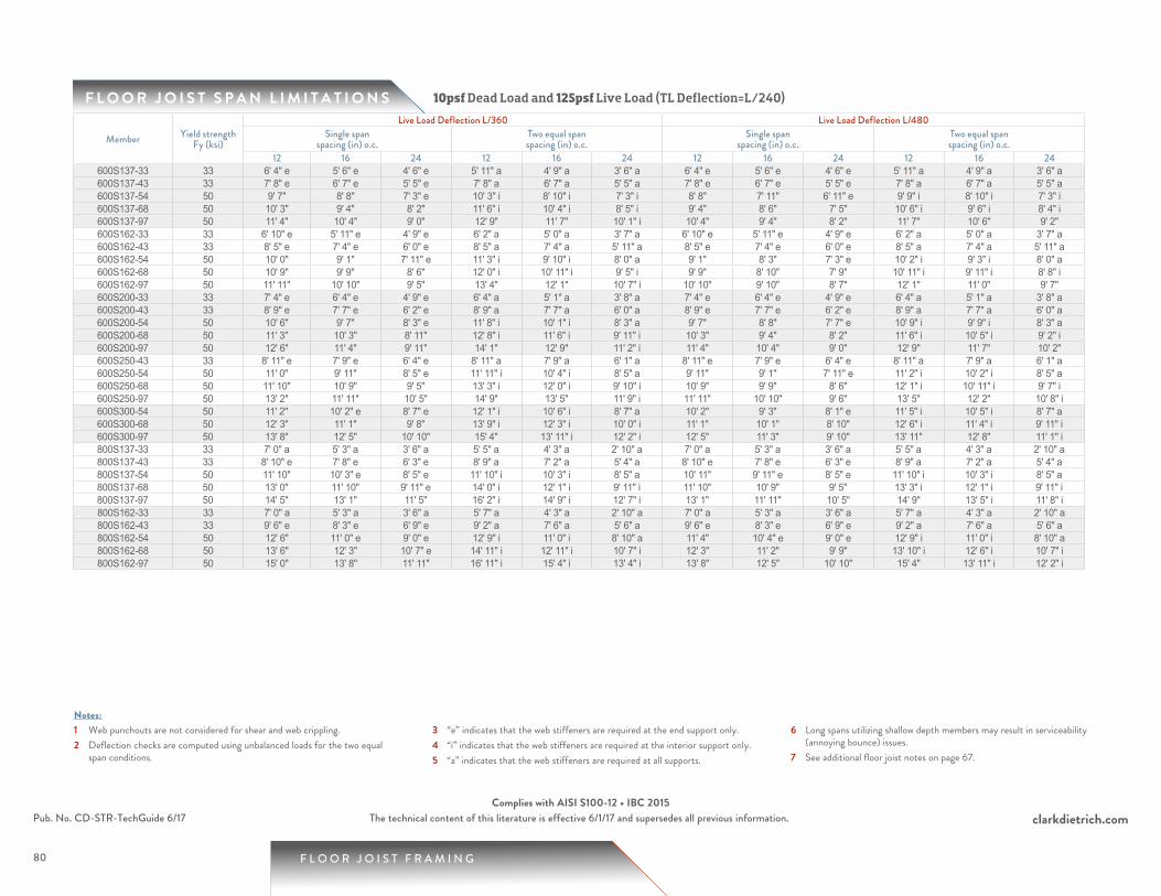
80
F L O O R J O I S T S P A N L I M I T A T I O N S
1 Web punchouts are not considered for shear and web crippling.2 Deflection checks are computed using unbalanced loads for the two equal
span conditions.
3 “e” indicates that the web stiffeners are required at the end support only.4 “i” indicates that the web stiffeners are required at the interior support only.5 “a” indicates that the web stiffeners are required at all supports.
6 Long spans utilizing shallow depth members may result in serviceability (annoying bounce) issues.
7 See additional floor joist notes on page 67.
Notes:
F L O O R J O I S T F R A M I N G
clarkdietrich.comPub. No. CD-STR-TechGuide 6/17 The technical content of this literature is effective 6/1/17 and supersedes all previous information.Complies with AISI S100-12 • IBC 2015
10psf Dead Load and 125psf Live Load (TL Deflection=L/240)
Member Yield strength Fy (ksi)
Live Load Deflection L/360 Live Load Deflection L/480Single span
spacing (in) o.c.Two equal spanspacing (in) o.c.
Single spanspacing (in) o.c.
Two equal spanspacing (in) o.c.
12 16 24 12 16 24 12 16 24 12 16 24600S137-33 33 6' 4" e 5' 6" e 4' 6" e 5' 11" a 4' 9" a 3' 6" a 6' 4" e 5' 6" e 4' 6" e 5' 11" a 4' 9" a 3' 6" a600S137-43 33 7' 8" e 6' 7" e 5' 5" e 7' 8" a 6' 7" a 5' 5" a 7' 8" e 6' 7" e 5' 5" e 7' 8" a 6' 7" a 5' 5" a600S137-54 50 9' 7" 8' 8" 7' 3" e 10' 3" i 8' 10" i 7' 3" i 8' 8" 7' 11" 6' 11" e 9' 9" i 8' 10" i 7' 3" i600S137-68 50 10' 3" 9' 4" 8' 2" 11' 6" i 10' 4" i 8' 5" i 9' 4" 8' 6" 7' 5" 10' 6" i 9' 6" i 8' 4" i600S137-97 50 11' 4" 10' 4" 9' 0" 12' 9" 11' 7" 10' 1" i 10' 4" 9' 4" 8' 2" 11' 7" 10' 6" 9' 2" 600S162-33 33 6' 10" e 5' 11" e 4' 9" e 6' 2" a 5' 0" a 3' 7" a 6' 10" e 5' 11" e 4' 9" e 6' 2" a 5' 0" a 3' 7" a600S162-43 33 8' 5" e 7' 4" e 6' 0" e 8' 5" a 7' 4" a 5' 11" a 8' 5" e 7' 4" e 6' 0" e 8' 5" a 7' 4" a 5' 11" a600S162-54 50 10' 0" 9' 1" 7' 11" e 11' 3" i 9' 10" i 8' 0" a 9' 1" 8' 3" 7' 3" e 10' 2" i 9' 3" i 8' 0" a600S162-68 50 10' 9" 9' 9" 8' 6" 12' 0" i 10' 11" i 9' 5" i 9' 9" 8' 10" 7' 9" 10' 11" i 9' 11" i 8' 8" i600S162-97 50 11' 11" 10' 10" 9' 5" 13' 4" 12' 1" 10' 7" i 10' 10" 9' 10" 8' 7" 12' 1" 11' 0" 9' 7" 600S200-33 33 7' 4" e 6' 4" e 4' 9" e 6' 4" a 5' 1" a 3' 8" a 7' 4" e 6' 4" e 4' 9" e 6' 4" a 5' 1" a 3' 8" a600S200-43 33 8' 9" e 7' 7" e 6' 2" e 8' 9" a 7' 7" a 6' 0" a 8' 9" e 7' 7" e 6' 2" e 8' 9" a 7' 7" a 6' 0" a600S200-54 50 10' 6" 9' 7" 8' 3" e 11' 8" i 10' 1" i 8' 3" a 9' 7" 8' 8" 7' 7" e 10' 9" i 9' 9" i 8' 3" a600S200-68 50 11' 3" 10' 3" 8' 11" 12' 8" i 11' 6" i 9' 11" i 10' 3" 9' 4" 8' 2" 11' 6" i 10' 5" i 9' 2" i600S200-97 50 12' 6" 11' 4" 9' 11" 14' 1" 12' 9" 11' 2" i 11' 4" 10' 4" 9' 0" 12' 9" 11' 7" 10' 2" 600S250-43 33 8' 11" e 7' 9" e 6' 4" e 8' 11" a 7' 9" a 6' 1" a 8' 11" e 7' 9" e 6' 4" e 8' 11" a 7' 9" a 6' 1" a600S250-54 50 11' 0" 9' 11" 8' 5" e 11' 11" i 10' 4" i 8' 5" a 9' 11" 9' 1" 7' 11" e 11' 2" i 10' 2" i 8' 5" a600S250-68 50 11' 10" 10' 9" 9' 5" 13' 3" i 12' 0" i 9' 10" i 10' 9" 9' 9" 8' 6" 12' 1" i 10' 11" i 9' 7" i600S250-97 50 13' 2" 11' 11" 10' 5" 14' 9" 13' 5" 11' 9" i 11' 11" 10' 10" 9' 6" 13' 5" 12' 2" 10' 8" i600S300-54 50 11' 2" 10' 2" e 8' 7" e 12' 1" i 10' 6" i 8' 7" a 10' 2" 9' 3" 8' 1" e 11' 5" i 10' 5" i 8' 7" a600S300-68 50 12' 3" 11' 1" 9' 8" 13' 9" i 12' 3" i 10' 0" i 11' 1" 10' 1" 8' 10" 12' 6" i 11' 4" i 9' 11" i600S300-97 50 13' 8" 12' 5" 10' 10" 15' 4" 13' 11" i 12' 2" i 12' 5" 11' 3" 9' 10" 13' 11" 12' 8" 11' 1" i800S137-33 33 7' 0" a 5' 3" a 3' 6" a 5' 5" a 4' 3" a 2' 10" a 7' 0" a 5' 3" a 3' 6" a 5' 5" a 4' 3" a 2' 10" a800S137-43 33 8' 10" e 7' 8" e 6' 3" e 8' 9" a 7' 2" a 5' 4" a 8' 10" e 7' 8" e 6' 3" e 8' 9" a 7' 2" a 5' 4" a800S137-54 50 11' 10" 10' 3" e 8' 5" e 11' 10" i 10' 3" i 8' 5" a 10' 11" 9' 11" e 8' 5" e 11' 10" i 10' 3" i 8' 5" a800S137-68 50 13' 0" 11' 10" 9' 11" e 14' 0" i 12' 1" i 9' 11" i 11' 10" 10' 9" 9' 5" 13' 3" i 12' 1" i 9' 11" i800S137-97 50 14' 5" 13' 1" 11' 5" 16' 2" i 14' 9" i 12' 7" i 13' 1" 11' 11" 10' 5" 14' 9" 13' 5" i 11' 8" i800S162-33 33 7' 0" a 5' 3" a 3' 6" a 5' 7" a 4' 3" a 2' 10" a 7' 0" a 5' 3" a 3' 6" a 5' 7" a 4' 3" a 2' 10" a800S162-43 33 9' 6" e 8' 3" e 6' 9" e 9' 2" a 7' 6" a 5' 6" a 9' 6" e 8' 3" e 6' 9" e 9' 2" a 7' 6" a 5' 6" a800S162-54 50 12' 6" 11' 0" e 9' 0" e 12' 9" i 11' 0" i 8' 10" a 11' 4" 10' 4" e 9' 0" e 12' 9" i 11' 0" i 8' 10" a800S162-68 50 13' 6" 12' 3" 10' 7" e 14' 11" i 12' 11" i 10' 7" i 12' 3" 11' 2" 9' 9" 13' 10" i 12' 6" i 10' 7" i800S162-97 50 15' 0" 13' 8" 11' 11" 16' 11" i 15' 4" i 13' 4" i 13' 8" 12' 5" 10' 10" 15' 4" 13' 11" i 12' 2" i

81
F L O O R J O I S T S P A N L I M I T A T I O N S
F L O O R J O I S T F R A M I N G
clarkdietrich.comPub. No. CD-STR-TechGuide 6/17 The technical content of this literature is effective 6/1/17 and supersedes all previous information.Complies with AISI S100-12 • IBC 2015
1 Web punchouts are not considered for shear and web crippling.2 Deflection checks are computed using unbalanced loads for the two equal
span conditions.
3 “e” indicates that the web stiffeners are required at the end support only.4 “i” indicates that the web stiffeners are required at the interior support only.5 “a” indicates that the web stiffeners are required at all supports.
6 Long spans utilizing shallow depth members may result in serviceability (annoying bounce) issues.
7 See additional floor joist notes on page 67.
Notes:
10psf Dead Load and 125psf Live Load (TL Deflection=L/240)
Member Yield strength Fy (ksi)
Live Load Deflection L/360 Live Load Deflection L/480Single span
spacing (in) o.c.Two equal spanspacing (in) o.c.
Single spanspacing (in) o.c.
Two equal spanspacing (in) o.c.
12 16 24 12 16 24 12 16 24 12 16 24800S200-33 33 7' 0" a 5' 3" a 3' 6" a 5' 7" a 4' 3" a 2' 10" a 7' 0" a 5' 3" a 3' 6" a 5' 7" a 4' 3" a 2' 10" a800S200-43 33 10' 2" e 8' 10" e 7' 2" e 9' 7" a 7' 9" a 5' 9" a 10' 2" e 8' 10" e 7' 2" e 9' 7" a 7' 9" a 5' 9" a800S200-54 50 13' 2" e 11' 9" e 9' 7" e 13' 7" i 11' 9" a 9' 3" a 12' 0" 10' 11" e 9' 6" e 13' 6" i 11' 9" a 9' 3" a800S200-68 50 14' 2" 12' 11" 11' 3" e 15' 11" i 14' 3" i 11' 7" a 12' 11" 11' 8" 10' 3" e 14' 5" i 13' 2" i 11' 6" a800S200-97 50 15' 9" 14' 4" 12' 6" 17' 8" 16' 1" i 14' 1" i 14' 4" 13' 0" 11' 4" 16' 1" 14' 7" 12' 9" i800S250-43 33 10' 5" e 9' 0" e 7' 5" e 9' 8" a 7' 10" a 5' 9" a 10' 5" e 9' 0" e 7' 5" e 9' 8" a 7' 10" a 5' 9" a800S250-54 50 13' 9" e 12' 0" e 9' 10" e 13' 11" i 12' 0" a 9' 4" a 12' 6" 11' 4" e 9' 10" e 13' 11" i 12' 0" a 9' 4" a800S250-68 50 14' 9" 13' 5" 11' 6" e 16' 4" i 14' 1" i 11' 6" a 13' 5" 12' 2" 10' 8" e 15' 1" i 13' 8" i 11' 6" a800S250-97 50 16' 6" 15' 0" 13' 1" 18' 6" i 16' 10" i 14' 8" i 15' 0" 13' 7" 11' 11" 16' 10" 15' 3" i 13' 4" i800S300-54 50 14' 0" e 12' 2" e 10' 0" e 14' 1" i 12' 2" a 9' 5" a 12' 9" 11' 7" e 10' 0" e 14' 1" i 12' 2" a 9' 5" a800S300-68 50 15' 3" 13' 10" 11' 8" e 16' 7" i 14' 4" i 11' 8" a 13' 10" 12' 7" 11' 0" e 15' 6" i 14' 1" i 11' 8" a800S300-97 50 17' 1" 15' 6" 13' 6" 19' 2" i 17' 5" i 14' 11" i 15' 6" 14' 1" 12' 4" 17' 5" 15' 10" i 13' 10" i1000S162-43 33 10' 6" a 9' 2" a 6' 2" a 8' 9" a 7' 0" a 4' 11" a 10' 6" a 9' 2" a 6' 2" a 8' 9" a 7' 0" a 4' 11" a1000S162-54 50 14' 1" e 12' 3" e 10' 0" e 13' 11" i 11' 5" a 8' 6" a 13' 6" e 12' 3" e 10' 0" e 13' 11" i 11' 5" a 8' 6" a1000S162-68 50 16' 1" 14' 5" e 11' 10" e 16' 8" i 14' 5" i 11' 10" a 14' 8" 13' 4" 11' 7" e 16' 5" i 14' 5" i 11' 10" a1000S162-97 50 18' 1" 16' 5" 14' 4" 20' 4" i 18' 6" i 15' 1" i 16' 5" 14' 11" 13' 1" 18' 6" i 16' 9" i 14' 8" i1000S200-43 33 11' 4" a 9' 3" a 6' 2" a 9' 1" a 7' 3" a 4' 11" a 11' 4" a 9' 3" a 6' 2" a 9' 1" a 7' 3" a 4' 11" a1000S200-54 50 15' 2" e 13' 2" e 10' 9" e 14' 7" a 11' 11" a 8' 10" a 14' 2" e 12' 10" e 10' 9" e 14' 7" a 11' 11" a 8' 10" a1000S200-68 50 16' 10" 15' 4" e 12' 7" e 17' 10" i 15' 6" i 12' 7" a 15' 4" 13' 11" 12' 2" e 17' 2" i 15' 6" i 12' 7" a1000S200-97 50 18' 11" 17' 2" 15' 0" 21' 3" i 19' 3" i 16' 1" i 17' 2" 15' 7" 13' 8" 19' 3" i 17' 6" i 15' 4" i1000S250-54 50 15' 7" e 13' 6" e 11' 0" e 14' 10" a 12' 1" a 8' 11" a 14' 11" e 13' 6" e 11' 0" e 14' 10" a 12' 1" a 8' 11" a1000S250-68 50 17' 8" 15' 11" e 13' 0" e 18' 4" i 15' 11" i 13' 0" a 16' 0" 14' 7" e 12' 9" e 18' 0" i 15' 11" i 13' 0" a1000S250-97 50 19' 8" 17' 11" 15' 8" 22' 1" i 20' 1" i 17' 3" i 17' 11" 16' 3" 14' 2" 20' 1" i 18' 3" i 15' 11" i1000S300-54 50 15' 10" e 13' 8" e 11' 2" e 14' 11" a 12' 2" a 9' 0" a 15' 3" e 13' 8" e 11' 2" e 14' 11" a 12' 2" a 9' 0" a1000S300-68 50 18' 2" 16' 2" e 13' 2" e 18' 8" i 16' 2" i 13' 2" a 16' 6" 15' 0" e 13' 1" e 18' 6" i 16' 2" i 13' 2" a1000S300-97 50 20' 4" 18' 5" 16' 1" 22' 10" i 20' 8" i 16' 11" i 18' 5" 16' 9" 14' 8" 20' 9" i 18' 10" i 16' 5" i1200S162-54 50 15' 2" a 13' 2" a 10' 2" a 13' 6" a 10' 10" a 7' 11" a 15' 2" a 13' 2" a 10' 2" a 13' 6" a 10' 10" a 7' 11" a1200S162-68 50 18' 1" 15' 8" e 12' 9" e 18' 1" i 15' 8" i 12' 3" a 16' 11" 15' 4" e 12' 9" e 18' 1" i 15' 8" i 12' 3" a1200S162-97 50 21' 1" 19' 2" 16' 7" 23' 5" i 20' 4" i 16' 7" i 19' 2" 17' 5" 15' 2" 21' 6" i 19' 6" i 16' 7" i1200S200-54 50 16' 5" a 14' 3" a 10' 2" a 14' 0" a 11' 3" a 8' 2" a 16' 3" a 14' 3" a 10' 2" a 14' 0" a 11' 3" a 8' 2" a1200S200-68 50 19' 5" e 16' 10" e 13' 9" e 19' 5" i 16' 10" a 12' 10" a 17' 7" 16' 0" e 13' 9" e 19' 5" i 16' 10" a 12' 10" a1200S200-97 50 21' 11" 19' 11" 17' 5" 24' 8" i 21' 8" i 17' 8" i 19' 11" 18' 1" 15' 10" 22' 4" i 20' 4" i 17' 8" i
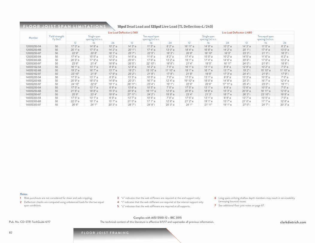
82
F L O O R J O I S T S P A N L I M I T A T I O N S
1 Web punchouts are not considered for shear and web crippling.2 Deflection checks are computed using unbalanced loads for the two equal
span conditions.
3 “e” indicates that the web stiffeners are required at the end support only.4 “i” indicates that the web stiffeners are required at the interior support only.5 “a” indicates that the web stiffeners are required at all supports.
6 Long spans utilizing shallow depth members may result in serviceability (annoying bounce) issues.
7 See additional floor joist notes on page 67.
Notes:
F L O O R J O I S T F R A M I N G
clarkdietrich.comPub. No. CD-STR-TechGuide 6/17 The technical content of this literature is effective 6/1/17 and supersedes all previous information.Complies with AISI S100-12 • IBC 2015
10psf Dead Load and 125psf Live Load (TL Deflection=L/240)
Member Yield strength Fy (ksi)
Live Load Deflection L/360 Live Load Deflection L/480Single span
spacing (in) o.c.Two equal spanspacing (in) o.c.
Single spanspacing (in) o.c.
Two equal spanspacing (in) o.c.
12 16 24 12 16 24 12 16 24 12 16 241200S250-54 50 17' 0" a 14' 9" a 10' 2" a 14' 3" a 11' 5" a 8' 2" a 16' 11" a 14' 9" a 10' 2" a 14' 3" a 11' 5" a 8' 2" a1200S250-68 50 20' 1" e 17' 5" e 14' 2" e 20' 1" i 17' 4" a 13' 0" a 18' 4" e 16' 8" e 14' 2" e 20' 1" i 17' 4" a 13' 0" a1200S250-97 50 22' 9" 20' 8" 18' 1" e 25' 7" i 22' 5" i 18' 3" i 20' 8" 18' 10" 16' 5" 23' 3" i 21' 1" i 18' 3" i1200S300-54 50 17' 4" a 15' 0" a 10' 2" a 14' 5" a 11' 6" a 8' 2" a 17' 4" a 15' 0" a 10' 2" a 14' 5" a 11' 6" a 8' 2" a1200S300-68 50 20' 6" e 17' 9" e 14' 6" e 20' 6" i 17' 6" a 13' 2" a 19' 1" e 17' 4" e 14' 6" e 20' 6" i 17' 6" a 13' 2" a1200S300-97 50 23' 6" 21' 4" 18' 8" e 26' 5" i 22' 10" i 18' 8" i 21' 4" 19' 5" 16' 11" 24' 0" i 21' 9" i 18' 8" i1400S162-54 50 16' 1" a 13' 1" a 8' 9" a 12' 9" a 10' 2" a 7' 0" a 16' 1" a 13' 1" a 8' 9" a 12' 9" a 10' 2" a 7' 0" a1400S162-68 50 19' 2" e 16' 7" e 13' 7" e 19' 2" i 15' 10" a 11' 10" a 19' 1" e 16' 7" e 13' 7" e 19' 2" i 15' 10" a 11' 10" a1400S162-97 50 23' 10" 21' 8" 17' 9" e 25' 2" i 21' 9" i 17' 9" i 21' 8" 19' 8" 17' 3" e 24' 4" i 21' 9" i 17' 9" i1400S200-54 50 17' 5" a 13' 1" a 8' 9" a 13' 3" a 10' 5" a 7' 0" a 17' 5" a 13' 1" a 8' 9" a 13' 3" a 10' 5" a 7' 0" a1400S200-68 50 20' 9" e 18' 0" e 14' 8" e 20' 3" i 16' 7" a 12' 4" a 19' 10" e 18' 0" e 14' 8" e 20' 3" i 16' 7" a 12' 4" a1400S200-97 50 24' 10" 22' 6" 19' 1" e 26' 11" i 23' 4" i 19' 1" i 22' 6" 20' 6" 17' 11" e 25' 4" i 23' 0" i 19' 1" i1400S250-54 50 17' 5" a 13' 1" a 8' 9" a 13' 6" a 10' 5" a 7' 0" a 17' 5" a 13' 1" a 8' 9" a 13' 6" a 10' 5" a 7' 0" a1400S250-68 50 21' 6" e 18' 8" e 15' 3" e 20' 9" a 16' 11" a 12' 6" a 20' 8" e 18' 8" e 15' 3" e 20' 9" a 16' 11" a 12' 6" a1400S250-97 50 25' 9" 23' 4" 19' 9" e 27' 11" i 24' 2" i 19' 9" a 23' 4" 21' 3" 18' 7" e 26' 3" i 23' 10" i 19' 9" a1400S300-54 50 17' 5" a 13' 1" a 8' 9" a 13' 7" a 10' 5" a 7' 0" a 17' 5" a 13' 1" a 8' 9" a 13' 7" a 10' 5" a 7' 0" a1400S300-68 50 22' 0" e 19' 1" e 15' 7" e 21' 0" a 17' 1" a 12' 8" a 21' 2" e 19' 1" e 15' 7" e 21' 0" a 17' 1" a 12' 8" a1400S300-97 50 26' 6" 24' 1" 20' 3" e 28' 7" i 24' 9" i 20' 3" a 24' 1" 21' 11" 19' 1" e 27' 0" i 24' 7" i 20' 3" a

83
F L O O R J O I S T S P A N L I M I T A T I O N S
F L O O R J O I S T F R A M I N G
clarkdietrich.comPub. No. CD-STR-TechGuide 6/17 The technical content of this literature is effective 6/1/17 and supersedes all previous information.Complies with AISI S100-12 • IBC 2015
1 Web punchouts are not considered for shear and web crippling.2 Deflection checks are computed using unbalanced loads for the two equal
span conditions.
3 “e” indicates that the web stiffeners are required at the end support only.4 “i” indicates that the web stiffeners are required at the interior support only.5 “a” indicates that the web stiffeners are required at all supports.
6 Long spans utilizing shallow depth members may result in serviceability (annoying bounce) issues.
7 See additional floor joist notes on page 67.
Notes:
15psf Dead Load and 125psf Live Load (TL Deflection=L/240)
Member Yield strength Fy (ksi)
Live Load Deflection L/360 Live Load Deflection L/480Single span
spacing (in) o.c.Two equal spanspacing (in) o.c.
Single spanspacing (in) o.c.
Two equal spanspacing (in) o.c.
12 16 24 12 16 24 12 16 24 12 16 24600S137-33 33 6' 3" e 5' 5" e 4' 5" e 5' 9" a 4' 8" a 3' 5" a 6' 3" e 5' 5" e 4' 5" e 5' 9" a 4' 8" a 3' 5" a600S137-43 33 7' 6" e 6' 6" e 5' 4" e 7' 6" a 6' 6" a 5' 4" a 7' 6" e 6' 6" e 5' 4" e 7' 6" a 6' 6" a 5' 4" a600S137-54 50 9' 7" 8' 8" 7' 1" e 10' 1" i 8' 9" i 7' 1" i 8' 8" 7' 11" 6' 11" e 9' 9" i 8' 9" i 7' 1" i600S137-68 50 10' 3" 9' 4" 8' 2" 11' 6" i 10' 2" i 8' 4" i 9' 4" 8' 6" 7' 5" 10' 6" i 9' 6" i 8' 4" i600S137-97 50 11' 4" 10' 4" 9' 0" 12' 9" 11' 7" 10' 1" i 10' 4" 9' 4" 8' 2" 11' 7" 10' 6" 9' 2" 600S162-33 33 6' 9" e 5' 10" e 4' 7" e 6' 0" a 4' 10" a 3' 6" a 6' 9" e 5' 10" e 4' 7" e 6' 0" a 4' 10" a 3' 6" a600S162-43 33 8' 4" e 7' 2" e 5' 10" e 8' 4" a 7' 2" a 5' 9" a 8' 4" e 7' 2" e 5' 10" e 8' 4" a 7' 2" a 5' 9" a600S162-54 50 10' 0" 9' 1" 7' 10" e 11' 1" i 9' 7" i 7' 10" a 9' 1" 8' 3" 7' 3" e 10' 2" i 9' 3" i 7' 10" a600S162-68 50 10' 9" 9' 9" 8' 6" 12' 0" i 10' 11" i 9' 3" i 9' 9" 8' 10" 7' 9" 10' 11" i 9' 11" i 8' 8" i600S162-97 50 11' 11" 10' 10" 9' 5" 13' 4" 12' 1" 10' 7" i 10' 10" 9' 10" 8' 7" 12' 1" 11' 0" 9' 7" i600S200-33 33 7' 2" e 6' 2" e 4' 7" e 6' 2" a 5' 0" a 3' 7" a 7' 2" e 6' 2" e 4' 7" e 6' 2" a 5' 0" a 3' 7" a600S200-43 33 8' 7" e 7' 5" e 6' 1" e 8' 7" a 7' 5" a 5' 11" a 8' 7" e 7' 5" e 6' 1" e 8' 7" a 7' 5" a 5' 11" a600S200-54 50 10' 6" 9' 7" 8' 1" e 11' 5" i 9' 11" i 8' 1" a 9' 7" 8' 8" 7' 7" e 10' 9" i 9' 9" i 8' 1" a600S200-68 50 11' 3" 10' 3" 8' 11" 12' 8" i 11' 6" i 9' 9" i 10' 3" 9' 4" 8' 2" 11' 6" i 10' 5" i 9' 2" i600S200-97 50 12' 6" 11' 4" 9' 11" 14' 1" 12' 9" 11' 2" i 11' 4" 10' 4" 9' 0" 12' 9" 11' 7" 10' 2" i600S250-43 33 8' 9" e 7' 7" e 6' 3" e 8' 9" a 7' 7" a 6' 0" a 8' 9" e 7' 7" e 6' 3" e 8' 9" a 7' 7" a 6' 0" a600S250-54 50 11' 0" 9' 11" e 8' 3" e 11' 8" i 10' 2" i 8' 3" a 9' 11" 9' 1" 7' 11" e 11' 2" i 10' 2" i 8' 3" a600S250-68 50 11' 10" 10' 9" 9' 5" 13' 3" i 11' 10" i 9' 8" i 10' 9" 9' 9" 8' 6" 12' 1" i 10' 11" i 9' 7" i600S250-97 50 13' 2" 11' 11" 10' 5" 14' 9" 13' 5" i 11' 9" i 11' 11" 10' 10" 9' 6" 13' 5" 12' 2" 10' 8" i600S300-54 50 11' 2" 10' 2" e 8' 5" e 11' 11" i 10' 3" i 8' 5" a 10' 2" 9' 3" 8' 1" e 11' 5" i 10' 3" i 8' 5" a600S300-68 50 12' 3" 11' 1" 9' 8" 13' 9" i 12' 0" i 9' 10" i 11' 1" 10' 1" 8' 10" 12' 6" i 11' 4" i 9' 10" i600S300-97 50 13' 8" 12' 5" 10' 10" 15' 4" 13' 11" i 12' 2" i 12' 5" 11' 3" 9' 10" 13' 11" 12' 8" 11' 1" i800S137-33 33 6' 9" a 5' 1" a 3' 5" a 5' 3" a 4' 1" a 2' 8" a 6' 9" a 5' 1" a 3' 5" a 5' 3" a 4' 1" a 2' 8" a800S137-43 33 8' 8" e 7' 6" e 6' 2" e 8' 7" a 7' 0" a 5' 2" a 8' 8" e 7' 6" e 6' 2" e 8' 7" a 7' 0" a 5' 2" a800S137-54 50 11' 8" 10' 1" e 8' 3" e 11' 8" i 10' 1" i 8' 3" a 10' 11" 9' 11" e 8' 3" e 11' 8" i 10' 1" i 8' 3" a800S137-68 50 13' 0" 11' 10" 9' 9" e 13' 9" i 11' 11" i 9' 9" i 11' 10" 10' 9" 9' 5" 13' 3" i 11' 11" i 9' 9" i800S137-97 50 14' 5" 13' 1" 11' 5" 16' 2" i 14' 9" i 12' 4" i 13' 1" 11' 11" 10' 5" 14' 9" 13' 5" i 11' 8" i800S162-33 33 6' 9" a 5' 1" a 3' 5" a 5' 5" a 4' 1" a 2' 8" a 6' 9" a 5' 1" a 3' 5" a 5' 5" a 4' 1" a 2' 8" a800S162-43 33 9' 4" e 8' 1" e 6' 7" e 9' 0" a 7' 4" a 5' 5" a 9' 4" e 8' 1" e 6' 7" e 9' 0" a 7' 4" a 5' 5" a800S162-54 50 12' 6" e 10' 10" e 8' 10" e 12' 6" i 10' 10" i 8' 8" a 11' 4" 10' 4" e 8' 10" e 12' 6" i 10' 10" i 8' 8" a800S162-68 50 13' 6" 12' 3" 10' 4" e 14' 8" i 12' 8" i 10' 4" i 12' 3" 11' 2" 9' 9" e 13' 10" i 12' 6" i 10' 4" i800S162-97 50 15' 0" 13' 8" 11' 11" 16' 11" i 15' 4" i 13' 1" i 13' 8" 12' 5" 10' 10" 15' 4" 13' 11" i 12' 2" i

84
F L O O R J O I S T S P A N L I M I T A T I O N S
1 Web punchouts are not considered for shear and web crippling.2 Deflection checks are computed using unbalanced loads for the two equal
span conditions.
3 “e” indicates that the web stiffeners are required at the end support only.4 “i” indicates that the web stiffeners are required at the interior support only.5 “a” indicates that the web stiffeners are required at all supports.
6 Long spans utilizing shallow depth members may result in serviceability (annoying bounce) issues.
7 See additional floor joist notes on page 67.
Notes:
F L O O R J O I S T F R A M I N G
clarkdietrich.comPub. No. CD-STR-TechGuide 6/17 The technical content of this literature is effective 6/1/17 and supersedes all previous information.Complies with AISI S100-12 • IBC 2015
15psf Dead Load and 125psf Live Load (TL Deflection=L/240)
Member Yield strength Fy (ksi)
Live Load Deflection L/360 Live Load Deflection L/480Single span
spacing (in) o.c.Two equal spanspacing (in) o.c.
Single spanspacing (in) o.c.
Two equal spanspacing (in) o.c.
12 16 24 12 16 24 12 16 24 12 16 24800S200-33 33 6' 9" a 5' 1" a 3' 5" a 5' 5" a 4' 1" a 2' 8" a 6' 9" a 5' 1" a 3' 5" a 5' 5" a 4' 1" a 2' 8" a800S200-43 33 10' 0" e 8' 8" e 7' 1" e 9' 4" a 7' 6" a 5' 7" a 10' 0" e 8' 8" e 7' 1" e 9' 4" a 7' 6" a 5' 7" a800S200-54 50 13' 2" e 11' 7" e 9' 5" e 13' 4" i 11' 7" a 9' 0" a 12' 0" 10' 11" e 9' 5" e 13' 4" i 11' 7" a 9' 0" a800S200-68 50 14' 2" 12' 11" 11' 3" e 15' 11" i 14' 0" i 11' 5" a 12' 11" 11' 8" 10' 3" e 14' 5" i 13' 2" i 11' 5" a800S200-97 50 15' 9" 14' 4" 12' 6" 17' 8" i 16' 1" i 14' 1" i 14' 4" 13' 0" 11' 4" 16' 1" 14' 7" i 12' 9" i800S250-43 33 10' 3" e 8' 11" e 7' 3" e 9' 6" a 7' 8" a 5' 8" a 10' 3" e 8' 11" e 7' 3" e 9' 6" a 7' 8" a 5' 8" a800S250-54 50 13' 8" e 11' 10" e 9' 8" e 13' 8" i 11' 10" a 9' 1" a 12' 6" 11' 4" e 9' 8" e 13' 8" i 11' 10" a 9' 1" a800S250-68 50 14' 9" 13' 5" 11' 4" e 16' 0" i 13' 10" i 11' 4" a 13' 5" 12' 2" 10' 8" e 15' 1" i 13' 8" i 11' 4" a800S250-97 50 16' 6" 15' 0" 13' 1" 18' 6" i 16' 10" i 14' 8" i 15' 0" 13' 7" 11' 11" 16' 10" 15' 3" i 13' 4" i800S300-54 50 13' 10" e 12' 0" e 9' 9" e 13' 10" i 12' 0" a 9' 2" a 12' 9" e 11' 7" e 9' 9" e 13' 10" i 12' 0" a 9' 2" a800S300-68 50 15' 3" 13' 10" 11' 6" e 16' 3" i 14' 1" i 11' 6" a 13' 10" 12' 7" 11' 0" e 15' 6" i 14' 1" i 11' 6" a800S300-97 50 17' 1" 15' 6" 13' 6" 19' 2" i 17' 5" i 14' 8" i 15' 6" 14' 1" 12' 4" 17' 5" 15' 10" i 13' 10" i1000S162-43 33 10' 4" a 8' 11" a 6' 0" a 8' 6" a 6' 9" a 4' 9" a 10' 4" a 8' 11" a 6' 0" a 8' 6" a 6' 9" a 4' 9" a1000S162-54 50 13' 10" e 12' 0" e 9' 10" e 13' 7" i 11' 2" a 8' 3" a 13' 6" e 12' 0" e 9' 10" e 13' 7" i 11' 2" a 8' 3" a1000S162-68 50 16' 1" 14' 2" e 11' 7" e 16' 5" i 14' 2" i 11' 7" a 14' 8" 13' 4" 11' 7" e 16' 5" i 14' 2" i 11' 7" a1000S162-97 50 18' 1" 16' 5" 14' 4" 20' 4" i 18' 2" i 14' 10" i 16' 5" 14' 11" 13' 1" 18' 6" i 16' 9" i 14' 8" i1000S200-43 33 11' 2" a 8' 11" a 6' 0" a 8' 10" a 7' 0" a 4' 9" a 11' 2" a 8' 11" a 6' 0" a 8' 10" a 7' 0" a 4' 9" a1000S200-54 50 14' 11" e 12' 11" e 10' 6" e 14' 3" a 11' 7" a 8' 6" a 14' 2" e 12' 10" e 10' 6" e 14' 3" a 11' 7" a 8' 6" a1000S200-68 50 16' 10" 15' 2" e 12' 5" e 17' 6" i 15' 2" i 12' 5" a 15' 4" 13' 11" e 12' 2" e 17' 2" i 15' 2" i 12' 5" a1000S200-97 50 18' 11" 17' 2" 15' 0" 21' 3" i 19' 3" i 15' 10" i 17' 2" 15' 7" 13' 8" 19' 3" i 17' 6" i 15' 4" i1000S250-54 50 15' 4" e 13' 3" e 10' 10" e 14' 6" a 11' 9" a 8' 8" a 14' 11" e 13' 3" e 10' 10" e 14' 6" a 11' 9" a 8' 8" a1000S250-68 50 17' 8" 15' 7" e 12' 9" e 18' 0" i 15' 7" i 12' 9" a 16' 0" 14' 7" e 12' 9" e 18' 0" i 15' 7" i 12' 9" a1000S250-97 50 19' 8" 17' 11" 15' 8" 22' 1" i 20' 1" i 16' 11" i 17' 11" 16' 3" 14' 2" 20' 1" i 18' 3" i 15' 11" i1000S300-54 50 15' 6" e 13' 5" e 11' 0" e 14' 7" a 11' 10" a 8' 8" a 15' 3" e 13' 5" e 11' 0" e 14' 7" a 11' 10" a 8' 8" a1000S300-68 50 18' 2" 15' 10" e 12' 11" e 18' 4" i 15' 10" a 12' 11" a 16' 6" 15' 0" e 12' 11" e 18' 4" i 15' 10" a 12' 11" a1000S300-97 50 20' 4" 18' 5" 16' 1" 22' 10" i 20' 4" i 16' 7" i 18' 5" 16' 9" 14' 8" 20' 9" i 18' 10" i 16' 5" i1200S162-54 50 14' 11" a 12' 11" a 9' 10" a 13' 2" a 10' 7" a 7' 8" a 14' 11" a 12' 11" a 9' 10" a 13' 2" a 10' 7" a 7' 8" a1200S162-68 50 17' 9" e 15' 4" e 12' 7" e 17' 9" i 15' 4" i 11' 11" a 16' 11" 15' 4" e 12' 7" e 17' 9" i 15' 4" i 11' 11" a1200S162-97 50 21' 1" 19' 2" 16' 3" 23' 0" i 19' 11" i 16' 3" i 19' 2" 17' 5" 15' 2" 21' 6" i 19' 6" i 16' 3" i1200S200-54 50 16' 2" a 14' 0" a 9' 10" a 13' 8" a 11' 0" a 7' 10" a 16' 2" a 14' 0" a 9' 10" a 13' 8" a 11' 0" a 7' 10" a1200S200-68 50 19' 1" e 16' 6" e 13' 6" e 19' 1" i 16' 6" a 12' 6" a 17' 7" 16' 0" e 13' 6" e 19' 1" i 16' 6" a 12' 6" a1200S200-97 50 21' 11" 19' 11" 17' 5" e 24' 7" i 21' 4" i 17' 5" i 19' 11" 18' 1" 15' 10" 22' 4" i 20' 4" i 17' 5" i

85
F L O O R J O I S T S P A N L I M I T A T I O N S
F L O O R J O I S T F R A M I N G
clarkdietrich.comPub. No. CD-STR-TechGuide 6/17 The technical content of this literature is effective 6/1/17 and supersedes all previous information.Complies with AISI S100-12 • IBC 2015
1 Web punchouts are not considered for shear and web crippling.2 Deflection checks are computed using unbalanced loads for the two equal
span conditions.
3 “e” indicates that the web stiffeners are required at the end support only.4 “i” indicates that the web stiffeners are required at the interior support only.5 “a” indicates that the web stiffeners are required at all supports.
6 Long spans utilizing shallow depth members may result in serviceability (annoying bounce) issues.
7 See additional floor joist notes on page 67.
Notes:
15psf Dead Load and 125psf Live Load (TL Deflection=L/240)
Member Yield strength Fy (ksi)
Live Load Deflection L/360 Live Load Deflection L/480Single span
spacing (in) o.c.Two equal spanspacing (in) o.c.
Single spanspacing (in) o.c.
Two equal spanspacing (in) o.c.
12 16 24 12 16 24 12 16 24 12 16 241200S250-54 50 16' 8" a 14' 5" a 9' 10" a 13' 10" a 11' 1" a 7' 10" a 16' 8" a 14' 5" a 9' 10" a 13' 10" a 11' 1" a 7' 10" a1200S250-68 50 19' 9" e 17' 1" e 13' 11" e 19' 9" i 16' 10" a 12' 8" a 18' 4" e 16' 8" e 13' 11" e 19' 9" i 16' 10" a 12' 8" a1200S250-97 50 22' 9" 20' 8" 18' 0" e 25' 5" i 22' 0" i 18' 0" i 20' 8" 18' 10" 16' 5" 23' 3" i 21' 1" i 18' 0" i1200S300-54 50 17' 0" a 14' 9" a 9' 10" a 14' 0" a 11' 3" a 7' 10" a 17' 0" a 14' 9" a 9' 10" a 14' 0" a 11' 3" a 7' 10" a1200S300-68 50 20' 1" e 17' 5" e 14' 3" e 20' 1" i 17' 1" a 12' 10" a 19' 1" e 17' 4" e 14' 3" e 20' 1" i 17' 1" a 12' 10" a1200S300-97 50 23' 6" 21' 4" 18' 4" e 25' 11" i 22' 5" i 18' 4" i 21' 4" 19' 5" 16' 11" e 24' 0" i 21' 9" i 18' 4" i1400S162-54 50 15' 9" a 12' 7" a 8' 5" a 12' 5" a 9' 10" a 6' 9" a 15' 9" a 12' 7" a 8' 5" a 12' 5" a 9' 10" a 6' 9" a1400S162-68 50 18' 10" e 16' 4" e 13' 4" e 18' 10" i 15' 5" a 11' 6" a 18' 10" e 16' 4" e 13' 4" e 18' 10" i 15' 5" a 11' 6" a1400S162-97 50 23' 10" 21' 5" 17' 6" e 24' 8" i 21' 5" i 17' 6" i 21' 8" 19' 8" 17' 3" e 24' 4" i 21' 5" i 17' 6" i1400S200-54 50 16' 10" a 12' 7" a 8' 5" a 12' 11" a 10' 1" a 6' 9" a 16' 10" a 12' 7" a 8' 5" a 12' 11" a 10' 1" a 6' 9" a1400S200-68 50 20' 4" e 17' 8" e 14' 5" e 19' 9" i 16' 2" a 12' 0" a 19' 10" e 17' 8" e 14' 5" e 19' 9" i 16' 2" a 12' 0" a1400S200-97 50 24' 10" 22' 6" 18' 9" e 26' 6" i 22' 11" i 18' 9" i 22' 6" 20' 6" 17' 11" e 25' 4" i 22' 11" i 18' 9" i1400S250-54 50 16' 10" a 12' 7" a 8' 5" a 13' 1" a 10' 1" a 6' 9" a 16' 10" a 12' 7" a 8' 5" a 13' 1" a 10' 1" a 6' 9" a1400S250-68 50 21' 2" e 18' 4" e 14' 11" e 20' 3" a 16' 6" a 12' 2" a 20' 8" e 18' 4" e 14' 11" e 20' 3" a 16' 6" a 12' 2" a1400S250-97 50 25' 9" 23' 4" 19' 5" e 27' 5" i 23' 9" i 19' 5" a 23' 4" 21' 3" 18' 7" e 26' 3" i 23' 9" i 19' 5" a1400S300-54 50 16' 10" a 12' 7" a 8' 5" a 13' 2" a 10' 1" a 6' 9" a 16' 10" a 12' 7" a 8' 5" a 13' 2" a 10' 1" a 6' 9" a1400S300-68 50 21' 8" e 18' 9" e 15' 4" e 20' 6" a 16' 8" a 12' 4" a 21' 2" e 18' 9" e 15' 4" e 20' 6" a 16' 8" a 12' 4" a1400S300-97 50 26' 6" 24' 1" 19' 10" e 28' 1" i 24' 4" i 19' 10" a 24' 1" 21' 11" 19' 1" e 27' 0" i 24' 4" i 19' 10" a

86
F L O O R J O I S T S P A N L I M I T A T I O N S
1 Web punchouts are not considered for shear and web crippling.2 Deflection checks are computed using unbalanced loads for the two equal
span conditions.
3 “e” indicates that the web stiffeners are required at the end support only.4 “i” indicates that the web stiffeners are required at the interior support only.5 “a” indicates that the web stiffeners are required at all supports.
6 Long spans utilizing shallow depth members may result in serviceability (annoying bounce) issues.
7 See additional floor joist notes on page 67.
Notes:
F L O O R J O I S T F R A M I N G
clarkdietrich.comPub. No. CD-STR-TechGuide 6/17 The technical content of this literature is effective 6/1/17 and supersedes all previous information.Complies with AISI S100-12 • IBC 2015
25psf Dead Load and 125psf Live Load (TL Deflection=L/240)
Member Yield strength Fy (ksi)
Live Load Deflection L/360 Live Load Deflection L/480Single span
spacing (in) o.c.Two equal spanspacing (in) o.c.
Single spanspacing (in) o.c.
Two equal spanspacing (in) o.c.
12 16 24 12 16 24 12 16 24 12 16 24600S137-33 33 6' 0" e 5' 3" e 4' 3" e 5' 5" a 4' 5" a 3' 3" a 6' 0" e 5' 3" e 4' 3" e 5' 5" a 4' 5" a 3' 3" a600S137-43 33 7' 3" e 6' 3" e 5' 2" e 7' 3" a 6' 3" a 5' 2" a 7' 3" e 6' 3" e 5' 2" e 7' 3" a 6' 3" a 5' 2" a600S137-54 50 9' 7" 8' 5" 6' 10" e 9' 9" i 8' 5" i 6' 10" i 8' 8" 7' 11" 6' 10" e 9' 9" i 8' 5" i 6' 10" i600S137-68 50 10' 3" 9' 4" 8' 0" 11' 4" i 9' 10" i 8' 0" i 9' 4" 8' 6" 7' 5" 10' 6" i 9' 6" i 8' 0" i600S137-97 50 11' 4" 10' 4" 9' 0" 12' 9" 11' 7" i 10' 1" i 10' 4" 9' 4" 8' 2" 11' 7" 10' 6" 9' 2" i600S162-33 33 6' 6" e 5' 7" e 4' 3" e 5' 8" a 4' 7" a 3' 4" a 6' 6" e 5' 7" e 4' 3" e 5' 8" a 4' 7" a 3' 4" a600S162-43 33 8' 0" e 6' 11" e 5' 8" e 8' 0" a 6' 11" a 5' 6" a 8' 0" e 6' 11" e 5' 8" e 8' 0" a 6' 11" a 5' 6" a600S162-54 50 10' 0" 9' 1" 7' 7" e 10' 9" i 9' 4" i 7' 7" a 9' 1" 8' 3" 7' 3" e 10' 2" i 9' 3" i 7' 7" a600S162-68 50 10' 9" 9' 9" 8' 6" 12' 0" i 10' 11" i 8' 11" i 9' 9" 8' 10" 7' 9" 10' 11" i 9' 11" i 8' 8" i600S162-97 50 11' 11" 10' 10" 9' 5" 13' 4" 12' 1" i 10' 7" i 10' 10" 9' 10" 8' 7" 12' 1" 11' 0" 9' 7" i600S200-33 33 6' 11" e 6' 0" e 4' 3" e 5' 11" a 4' 8" a 3' 5" a 6' 11" e 6' 0" e 4' 3" e 5' 11" a 4' 8" a 3' 5" a600S200-43 33 8' 3" e 7' 2" e 5' 10" e 8' 3" a 7' 2" a 5' 7" a 8' 3" e 7' 2" e 5' 10" e 8' 3" a 7' 2" a 5' 7" a600S200-54 50 10' 6" 9' 7" e 7' 10" e 11' 0" i 9' 7" i 7' 10" a 9' 7" 8' 8" 7' 7" e 10' 9" i 9' 7" i 7' 10" a600S200-68 50 11' 3" 10' 3" 8' 11" 12' 8" i 11' 6" i 9' 5" i 10' 3" 9' 4" 8' 2" 11' 6" i 10' 5" i 9' 2" i600S200-97 50 12' 6" 11' 4" 9' 11" 14' 1" 12' 9" i 11' 2" i 11' 4" 10' 4" 9' 0" 12' 9" 11' 7" 10' 2" i600S250-43 33 8' 6" e 7' 4" e 6' 0" e 8' 6" a 7' 4" a 5' 9" a 8' 6" e 7' 4" e 6' 0" e 8' 6" a 7' 4" a 5' 9" a600S250-54 50 11' 0" 9' 9" e 8' 0" e 11' 4" i 9' 9" i 8' 0" a 9' 11" 9' 1" 7' 11" e 11' 2" i 9' 9" i 8' 0" a600S250-68 50 11' 10" 10' 9" 9' 4" e 13' 2" i 11' 5" i 9' 4" i 10' 9" 9' 9" 8' 6" 12' 1" i 10' 11" i 9' 4" i600S250-97 50 13' 2" 11' 11" 10' 5" 14' 9" 13' 5" i 11' 9" i 11' 11" 10' 10" 9' 6" 13' 5" 12' 2" 10' 8" i600S300-54 50 11' 2" 9' 11" e 8' 1" e 11' 6" i 9' 11" i 8' 1" a 10' 2" 9' 3" e 8' 1" e 11' 5" i 9' 11" i 8' 1" a600S300-68 50 12' 3" 11' 1" 9' 6" e 13' 5" i 11' 7" i 9' 6" i 11' 1" 10' 1" 8' 10" 12' 6" i 11' 4" i 9' 6" i600S300-97 50 13' 8" 12' 5" 10' 10" 15' 4" i 13' 11" i 12' 0" i 12' 5" 11' 3" 9' 10" 13' 11" 12' 8" i 11' 1" i800S137-33 33 6' 4" a 4' 9" a 3' 2" a 5' 0" a 3' 9" a 2' 6" a 6' 4" a 4' 9" a 3' 2" a 5' 0" a 3' 9" a 2' 6" a800S137-43 33 8' 5" e 7' 3" e 5' 11" e 8' 2" a 6' 8" a 4' 11" a 8' 5" e 7' 3" e 5' 11" e 8' 2" a 6' 8" a 4' 11" a800S137-54 50 11' 3" 9' 9" e 7' 11" e 11' 3" i 9' 9" i 7' 10" a 10' 11" 9' 9" e 7' 11" e 11' 3" i 9' 9" i 7' 10" a800S137-68 50 13' 0" 11' 6" 9' 5" e 13' 3" i 11' 6" i 9' 5" i 11' 10" 10' 9" 9' 5" e 13' 3" i 11' 6" i 9' 5" i800S137-97 50 14' 5" 13' 1" 11' 5" 16' 2" i 14' 7" i 11' 11" i 13' 1" 11' 11" 10' 5" 14' 9" 13' 5" i 11' 8" i800S162-33 33 6' 4" a 4' 9" a 3' 2" a 5' 1" a 3' 9" a 2' 6" a 6' 4" a 4' 9" a 3' 2" a 5' 1" a 3' 9" a 2' 6" a800S162-43 33 9' 0" e 7' 10" e 6' 5" e 8' 6" a 6' 11" a 5' 1" a 9' 0" e 7' 10" e 6' 5" e 8' 6" a 6' 11" a 5' 1" a800S162-54 50 12' 1" e 10' 6" e 8' 6" e 12' 1" i 10' 6" a 8' 3" a 11' 4" 10' 4" e 8' 6" e 12' 1" i 10' 6" a 8' 3" a800S162-68 50 13' 6" 12' 3" 10' 0" e 14' 2" i 12' 3" i 10' 0" i 12' 3" 11' 2" 9' 9" e 13' 10" i 12' 3" i 10' 0" i800S162-97 50 15' 0" 13' 8" 11' 11" 16' 11" i 15' 4" i 12' 8" i 13' 8" 12' 5" 10' 10" 15' 4" 13' 11" i 12' 2" i
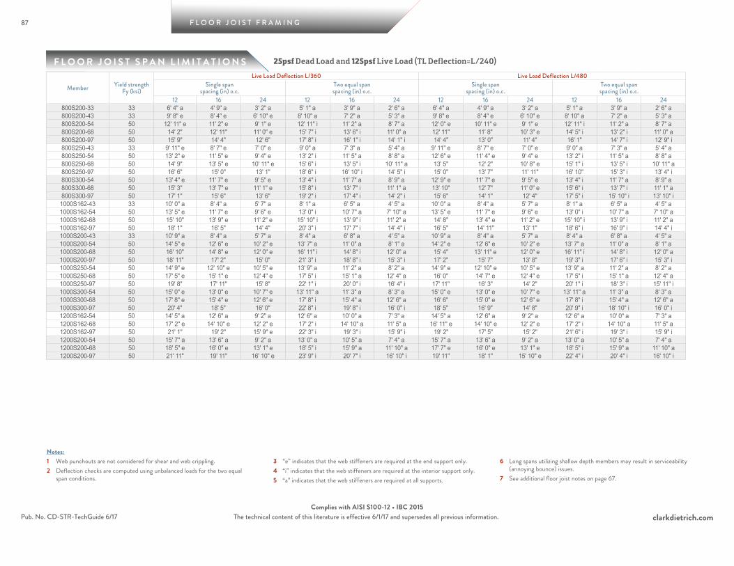
87
F L O O R J O I S T S P A N L I M I T A T I O N S
F L O O R J O I S T F R A M I N G
clarkdietrich.comPub. No. CD-STR-TechGuide 6/17 The technical content of this literature is effective 6/1/17 and supersedes all previous information.Complies with AISI S100-12 • IBC 2015
1 Web punchouts are not considered for shear and web crippling.2 Deflection checks are computed using unbalanced loads for the two equal
span conditions.
3 “e” indicates that the web stiffeners are required at the end support only.4 “i” indicates that the web stiffeners are required at the interior support only.5 “a” indicates that the web stiffeners are required at all supports.
6 Long spans utilizing shallow depth members may result in serviceability (annoying bounce) issues.
7 See additional floor joist notes on page 67.
Notes:
25psf Dead Load and 125psf Live Load (TL Deflection=L/240)
Member Yield strength Fy (ksi)
Live Load Deflection L/360 Live Load Deflection L/480Single span
spacing (in) o.c.Two equal spanspacing (in) o.c.
Single spanspacing (in) o.c.
Two equal spanspacing (in) o.c.
12 16 24 12 16 24 12 16 24 12 16 24800S200-33 33 6' 4" a 4' 9" a 3' 2" a 5' 1" a 3' 9" a 2' 6" a 6' 4" a 4' 9" a 3' 2" a 5' 1" a 3' 9" a 2' 6" a800S200-43 33 9' 8" e 8' 4" e 6' 10" e 8' 10" a 7' 2" a 5' 3" a 9' 8" e 8' 4" e 6' 10" e 8' 10" a 7' 2" a 5' 3" a800S200-54 50 12' 11" e 11' 2" e 9' 1" e 12' 11" i 11' 2" a 8' 7" a 12' 0" e 10' 11" e 9' 1" e 12' 11" i 11' 2" a 8' 7" a800S200-68 50 14' 2" 12' 11" 11' 0" e 15' 7" i 13' 6" i 11' 0" a 12' 11" 11' 8" 10' 3" e 14' 5" i 13' 2" i 11' 0" a800S200-97 50 15' 9" 14' 4" 12' 6" 17' 8" i 16' 1" i 14' 1" i 14' 4" 13' 0" 11' 4" 16' 1" 14' 7" i 12' 9" i800S250-43 33 9' 11" e 8' 7" e 7' 0" e 9' 0" a 7' 3" a 5' 4" a 9' 11" e 8' 7" e 7' 0" e 9' 0" a 7' 3" a 5' 4" a800S250-54 50 13' 2" e 11' 5" e 9' 4" e 13' 2" i 11' 5" a 8' 8" a 12' 6" e 11' 4" e 9' 4" e 13' 2" i 11' 5" a 8' 8" a800S250-68 50 14' 9" 13' 5" e 10' 11" e 15' 6" i 13' 5" i 10' 11" a 13' 5" 12' 2" 10' 8" e 15' 1" i 13' 5" i 10' 11" a800S250-97 50 16' 6" 15' 0" 13' 1" 18' 6" i 16' 10" i 14' 5" i 15' 0" 13' 7" 11' 11" 16' 10" 15' 3" i 13' 4" i800S300-54 50 13' 4" e 11' 7" e 9' 5" e 13' 4" i 11' 7" a 8' 9" a 12' 9" e 11' 7" e 9' 5" e 13' 4" i 11' 7" a 8' 9" a800S300-68 50 15' 3" 13' 7" e 11' 1" e 15' 8" i 13' 7" i 11' 1" a 13' 10" 12' 7" 11' 0" e 15' 6" i 13' 7" i 11' 1" a800S300-97 50 17' 1" 15' 6" 13' 6" 19' 2" i 17' 4" i 14' 2" i 15' 6" 14' 1" 12' 4" 17' 5" i 15' 10" i 13' 10" i1000S162-43 33 10' 0" a 8' 4" a 5' 7" a 8' 1" a 6' 5" a 4' 5" a 10' 0" a 8' 4" a 5' 7" a 8' 1" a 6' 5" a 4' 5" a1000S162-54 50 13' 5" e 11' 7" e 9' 6" e 13' 0" i 10' 7" a 7' 10" a 13' 5" e 11' 7" e 9' 6" e 13' 0" i 10' 7" a 7' 10" a1000S162-68 50 15' 10" 13' 9" e 11' 2" e 15' 10" i 13' 9" i 11' 2" a 14' 8" 13' 4" e 11' 2" e 15' 10" i 13' 9" i 11' 2" a1000S162-97 50 18' 1" 16' 5" 14' 4" 20' 3" i 17' 7" i 14' 4" i 16' 5" 14' 11" 13' 1" 18' 6" i 16' 9" i 14' 4" i1000S200-43 33 10' 9" a 8' 4" a 5' 7" a 8' 4" a 6' 8" a 4' 5" a 10' 9" a 8' 4" a 5' 7" a 8' 4" a 6' 8" a 4' 5" a1000S200-54 50 14' 5" e 12' 6" e 10' 2" e 13' 7" a 11' 0" a 8' 1" a 14' 2" e 12' 6" e 10' 2" e 13' 7" a 11' 0" a 8' 1" a1000S200-68 50 16' 10" 14' 8" e 12' 0" e 16' 11" i 14' 8" i 12' 0" a 15' 4" 13' 11" e 12' 0" e 16' 11" i 14' 8" i 12' 0" a1000S200-97 50 18' 11" 17' 2" 15' 0" 21' 3" i 18' 8" i 15' 3" i 17' 2" 15' 7" 13' 8" 19' 3" i 17' 6" i 15' 3" i1000S250-54 50 14' 9" e 12' 10" e 10' 5" e 13' 9" a 11' 2" a 8' 2" a 14' 9" e 12' 10" e 10' 5" e 13' 9" a 11' 2" a 8' 2" a1000S250-68 50 17' 5" e 15' 1" e 12' 4" e 17' 5" i 15' 1" a 12' 4" a 16' 0" 14' 7" e 12' 4" e 17' 5" i 15' 1" a 12' 4" a1000S250-97 50 19' 8" 17' 11" 15' 8" 22' 1" i 20' 0" i 16' 4" i 17' 11" 16' 3" 14' 2" 20' 1" i 18' 3" i 15' 11" i1000S300-54 50 15' 0" e 13' 0" e 10' 7" e 13' 11" a 11' 3" a 8' 3" a 15' 0" e 13' 0" e 10' 7" e 13' 11" a 11' 3" a 8' 3" a1000S300-68 50 17' 8" e 15' 4" e 12' 6" e 17' 8" i 15' 4" a 12' 6" a 16' 6" 15' 0" e 12' 6" e 17' 8" i 15' 4" a 12' 6" a1000S300-97 50 20' 4" 18' 5" 16' 0" 22' 8" i 19' 8" i 16' 0" i 18' 5" 16' 9" 14' 8" 20' 9" i 18' 10" i 16' 0" i1200S162-54 50 14' 5" a 12' 6" a 9' 2" a 12' 6" a 10' 0" a 7' 3" a 14' 5" a 12' 6" a 9' 2" a 12' 6" a 10' 0" a 7' 3" a1200S162-68 50 17' 2" e 14' 10" e 12' 2" e 17' 2" i 14' 10" a 11' 5" a 16' 11" e 14' 10" e 12' 2" e 17' 2" i 14' 10" a 11' 5" a1200S162-97 50 21' 1" 19' 2" 15' 9" e 22' 3" i 19' 3" i 15' 9" i 19' 2" 17' 5" 15' 2" 21' 6" i 19' 3" i 15' 9" i1200S200-54 50 15' 7" a 13' 6" a 9' 2" a 13' 0" a 10' 5" a 7' 4" a 15' 7" a 13' 6" a 9' 2" a 13' 0" a 10' 5" a 7' 4" a1200S200-68 50 18' 5" e 16' 0" e 13' 1" e 18' 5" i 15' 9" a 11' 10" a 17' 7" e 16' 0" e 13' 1" e 18' 5" i 15' 9" a 11' 10" a1200S200-97 50 21' 11" 19' 11" 16' 10" e 23' 9" i 20' 7" i 16' 10" i 19' 11" 18' 1" 15' 10" e 22' 4" i 20' 4" i 16' 10" i

88
F L O O R J O I S T S P A N L I M I T A T I O N S
1 Web punchouts are not considered for shear and web crippling.2 Deflection checks are computed using unbalanced loads for the two equal
span conditions.
3 “e” indicates that the web stiffeners are required at the end support only.4 “i” indicates that the web stiffeners are required at the interior support only.5 “a” indicates that the web stiffeners are required at all supports.
6 Long spans utilizing shallow depth members may result in serviceability (annoying bounce) issues.
7 See additional floor joist notes on page 67.
Notes:
F L O O R J O I S T F R A M I N G
clarkdietrich.comPub. No. CD-STR-TechGuide 6/17 The technical content of this literature is effective 6/1/17 and supersedes all previous information.Complies with AISI S100-12 • IBC 2015
25psf Dead Load and 125psf Live Load (TL Deflection=L/240)
Member Yield strength Fy (ksi)
Live Load Deflection L/360 Live Load Deflection L/480Single span
spacing (in) o.c.Two equal spanspacing (in) o.c.
Single spanspacing (in) o.c.
Two equal spanspacing (in) o.c.
12 16 24 12 16 24 12 16 24 12 16 241200S250-54 50 16' 1" a 13' 9" a 9' 2" a 13' 2" a 10' 6" a 7' 4" a 16' 1" a 13' 9" a 9' 2" a 13' 2" a 10' 6" a 7' 4" a1200S250-68 50 19' 1" e 16' 6" e 13' 6" e 19' 1" i 16' 1" a 12' 1" a 18' 4" e 16' 6" e 13' 6" e 19' 1" i 16' 1" a 12' 1" a1200S250-97 50 22' 9" 20' 8" 17' 4" e 24' 6" i 21' 3" i 17' 4" i 20' 8" 18' 10" 16' 5" e 23' 3" i 21' 1" i 17' 4" i1200S300-54 50 16' 5" a 13' 9" a 9' 2" a 13' 3" a 10' 7" a 7' 4" a 16' 5" a 13' 9" a 9' 2" a 13' 3" a 10' 7" a 7' 4" a1200S300-68 50 19' 5" e 16' 10" e 13' 9" e 19' 5" a 16' 3" a 12' 2" a 19' 1" e 16' 10" e 13' 9" e 19' 5" a 16' 3" a 12' 2" a1200S300-97 50 23' 6" 21' 4" 17' 9" e 25' 1" i 21' 8" i 17' 9" i 21' 4" 19' 5" 16' 11" e 24' 0" i 21' 8" i 17' 9" i1400S162-54 50 15' 3" a 11' 9" a 7' 10" a 11' 9" a 9' 4" a 6' 3" a 15' 3" a 11' 9" a 7' 10" a 11' 9" a 9' 4" a 6' 3" a1400S162-68 50 18' 3" e 15' 9" e 12' 11" e 18' 0" i 14' 8" a 10' 11" a 18' 3" e 15' 9" e 12' 11" e 18' 0" i 14' 8" a 10' 11" a1400S162-97 50 23' 10" 20' 8" 16' 10" e 23' 10" i 20' 8" i 16' 10" i 21' 8" 19' 8" 16' 10" e 23' 10" i 20' 8" i 16' 10" i1400S200-54 50 15' 8" a 11' 9" a 7' 10" a 12' 3" a 9' 5" a 6' 3" a 15' 8" a 11' 9" a 7' 10" a 12' 3" a 9' 5" a 6' 3" a1400S200-68 50 19' 8" e 17' 1" e 13' 11" e 18' 10" a 15' 4" a 11' 4" a 19' 8" e 17' 1" e 13' 11" e 18' 10" a 15' 4" a 11' 4" a1400S200-97 50 24' 10" 22' 2" 18' 1" e 25' 7" i 22' 2" i 18' 1" a 22' 6" 20' 6" 17' 11" e 25' 4" i 22' 2" i 18' 1" a1400S250-54 50 15' 8" a 11' 9" a 7' 10" a 12' 5" a 9' 5" a 6' 3" a 15' 8" a 11' 9" a 7' 10" a 12' 5" a 9' 5" a 6' 3" a1400S250-68 50 20' 5" e 17' 8" e 14' 5" e 19' 3" a 15' 8" a 11' 6" a 20' 5" e 17' 8" e 14' 5" e 19' 3" a 15' 8" a 11' 6" a1400S250-97 50 25' 9" 22' 11" 18' 9" e 26' 6" i 22' 11" i 18' 9" a 23' 4" 21' 3" 18' 7" e 26' 3" i 22' 11" i 18' 9" a1400S300-54 50 15' 8" a 11' 9" a 7' 10" a 12' 6" a 9' 5" a 6' 3" a 15' 8" a 11' 9" a 7' 10" a 12' 6" a 9' 5" a 6' 3" a1400S300-68 50 20' 11" e 18' 1" e 14' 9" e 19' 6" a 15' 10" a 11' 8" a 20' 11" e 18' 1" e 14' 9" e 19' 6" a 15' 10" a 11' 8" a1400S300-97 50 26' 6" 23' 6" e 19' 2" e 27' 1" i 23' 6" i 19' 2" a 24' 1" 21' 11" 19' 1" e 27' 0" i 23' 6" i 19' 2" a
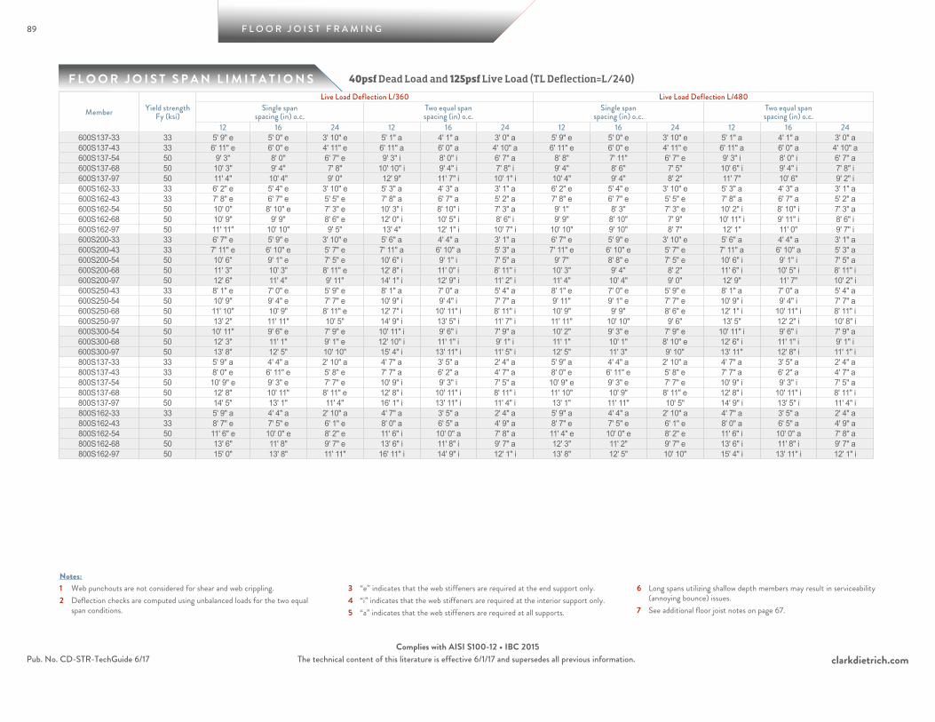
89
F L O O R J O I S T S P A N L I M I T A T I O N S
F L O O R J O I S T F R A M I N G
clarkdietrich.comPub. No. CD-STR-TechGuide 6/17 The technical content of this literature is effective 6/1/17 and supersedes all previous information.Complies with AISI S100-12 • IBC 2015
1 Web punchouts are not considered for shear and web crippling.2 Deflection checks are computed using unbalanced loads for the two equal
span conditions.
3 “e” indicates that the web stiffeners are required at the end support only.4 “i” indicates that the web stiffeners are required at the interior support only.5 “a” indicates that the web stiffeners are required at all supports.
6 Long spans utilizing shallow depth members may result in serviceability (annoying bounce) issues.
7 See additional floor joist notes on page 67.
Notes:
40psf Dead Load and 125psf Live Load (TL Deflection=L/240)
Member Yield strength Fy (ksi)
Live Load Deflection L/360 Live Load Deflection L/480Single span
spacing (in) o.c.Two equal spanspacing (in) o.c.
Single spanspacing (in) o.c.
Two equal spanspacing (in) o.c.
12 16 24 12 16 24 12 16 24 12 16 24600S137-33 33 5' 9" e 5' 0" e 3' 10" e 5' 1" a 4' 1" a 3' 0" a 5' 9" e 5' 0" e 3' 10" e 5' 1" a 4' 1" a 3' 0" a600S137-43 33 6' 11" e 6' 0" e 4' 11" e 6' 11" a 6' 0" a 4' 10" a 6' 11" e 6' 0" e 4' 11" e 6' 11" a 6' 0" a 4' 10" a600S137-54 50 9' 3" 8' 0" 6' 7" e 9' 3" i 8' 0" i 6' 7" a 8' 8" 7' 11" 6' 7" e 9' 3" i 8' 0" i 6' 7" a600S137-68 50 10' 3" 9' 4" 7' 8" 10' 10" i 9' 4" i 7' 8" i 9' 4" 8' 6" 7' 5" 10' 6" i 9' 4" i 7' 8" i600S137-97 50 11' 4" 10' 4" 9' 0" 12' 9" 11' 7" i 10' 1" i 10' 4" 9' 4" 8' 2" 11' 7" 10' 6" 9' 2" i600S162-33 33 6' 2" e 5' 4" e 3' 10" e 5' 3" a 4' 3" a 3' 1" a 6' 2" e 5' 4" e 3' 10" e 5' 3" a 4' 3" a 3' 1" a600S162-43 33 7' 8" e 6' 7" e 5' 5" e 7' 8" a 6' 7" a 5' 2" a 7' 8" e 6' 7" e 5' 5" e 7' 8" a 6' 7" a 5' 2" a600S162-54 50 10' 0" 8' 10" e 7' 3" e 10' 3" i 8' 10" i 7' 3" a 9' 1" 8' 3" 7' 3" e 10' 2" i 8' 10" i 7' 3" a600S162-68 50 10' 9" 9' 9" 8' 6" e 12' 0" i 10' 5" i 8' 6" i 9' 9" 8' 10" 7' 9" 10' 11" i 9' 11" i 8' 6" i600S162-97 50 11' 11" 10' 10" 9' 5" 13' 4" 12' 1" i 10' 7" i 10' 10" 9' 10" 8' 7" 12' 1" 11' 0" 9' 7" i600S200-33 33 6' 7" e 5' 9" e 3' 10" e 5' 6" a 4' 4" a 3' 1" a 6' 7" e 5' 9" e 3' 10" e 5' 6" a 4' 4" a 3' 1" a600S200-43 33 7' 11" e 6' 10" e 5' 7" e 7' 11" a 6' 10" a 5' 3" a 7' 11" e 6' 10" e 5' 7" e 7' 11" a 6' 10" a 5' 3" a600S200-54 50 10' 6" 9' 1" e 7' 5" e 10' 6" i 9' 1" i 7' 5" a 9' 7" 8' 8" e 7' 5" e 10' 6" i 9' 1" i 7' 5" a600S200-68 50 11' 3" 10' 3" 8' 11" e 12' 8" i 11' 0" i 8' 11" i 10' 3" 9' 4" 8' 2" 11' 6" i 10' 5" i 8' 11" i600S200-97 50 12' 6" 11' 4" 9' 11" 14' 1" i 12' 9" i 11' 2" i 11' 4" 10' 4" 9' 0" 12' 9" 11' 7" 10' 2" i600S250-43 33 8' 1" e 7' 0" e 5' 9" e 8' 1" a 7' 0" a 5' 4" a 8' 1" e 7' 0" e 5' 9" e 8' 1" a 7' 0" a 5' 4" a600S250-54 50 10' 9" 9' 4" e 7' 7" e 10' 9" i 9' 4" i 7' 7" a 9' 11" 9' 1" e 7' 7" e 10' 9" i 9' 4" i 7' 7" a600S250-68 50 11' 10" 10' 9" 8' 11" e 12' 7" i 10' 11" i 8' 11" i 10' 9" 9' 9" 8' 6" e 12' 1" i 10' 11" i 8' 11" i600S250-97 50 13' 2" 11' 11" 10' 5" 14' 9" i 13' 5" i 11' 7" i 11' 11" 10' 10" 9' 6" 13' 5" 12' 2" i 10' 8" i600S300-54 50 10' 11" 9' 6" e 7' 9" e 10' 11" i 9' 6" i 7' 9" a 10' 2" 9' 3" e 7' 9" e 10' 11" i 9' 6" i 7' 9" a600S300-68 50 12' 3" 11' 1" 9' 1" e 12' 10" i 11' 1" i 9' 1" i 11' 1" 10' 1" 8' 10" e 12' 6" i 11' 1" i 9' 1" i600S300-97 50 13' 8" 12' 5" 10' 10" 15' 4" i 13' 11" i 11' 5" i 12' 5" 11' 3" 9' 10" 13' 11" 12' 8" i 11' 1" i800S137-33 33 5' 9" a 4' 4" a 2' 10" a 4' 7" a 3' 5" a 2' 4" a 5' 9" a 4' 4" a 2' 10" a 4' 7" a 3' 5" a 2' 4" a800S137-43 33 8' 0" e 6' 11" e 5' 8" e 7' 7" a 6' 2" a 4' 7" a 8' 0" e 6' 11" e 5' 8" e 7' 7" a 6' 2" a 4' 7" a800S137-54 50 10' 9" e 9' 3" e 7' 7" e 10' 9" i 9' 3" i 7' 5" a 10' 9" e 9' 3" e 7' 7" e 10' 9" i 9' 3" i 7' 5" a800S137-68 50 12' 8" 10' 11" 8' 11" e 12' 8" i 10' 11" i 8' 11" i 11' 10" 10' 9" 8' 11" e 12' 8" i 10' 11" i 8' 11" i800S137-97 50 14' 5" 13' 1" 11' 4" 16' 1" i 13' 11" i 11' 4" i 13' 1" 11' 11" 10' 5" 14' 9" i 13' 5" i 11' 4" i800S162-33 33 5' 9" a 4' 4" a 2' 10" a 4' 7" a 3' 5" a 2' 4" a 5' 9" a 4' 4" a 2' 10" a 4' 7" a 3' 5" a 2' 4" a800S162-43 33 8' 7" e 7' 5" e 6' 1" e 8' 0" a 6' 5" a 4' 9" a 8' 7" e 7' 5" e 6' 1" e 8' 0" a 6' 5" a 4' 9" a800S162-54 50 11' 6" e 10' 0" e 8' 2" e 11' 6" i 10' 0" a 7' 8" a 11' 4" e 10' 0" e 8' 2" e 11' 6" i 10' 0" a 7' 8" a800S162-68 50 13' 6" 11' 8" 9' 7" e 13' 6" i 11' 8" i 9' 7" a 12' 3" 11' 2" 9' 7" e 13' 6" i 11' 8" i 9' 7" a800S162-97 50 15' 0" 13' 8" 11' 11" 16' 11" i 14' 9" i 12' 1" i 13' 8" 12' 5" 10' 10" 15' 4" i 13' 11" i 12' 1" i

90
F L O O R J O I S T S P A N L I M I T A T I O N S
1 Web punchouts are not considered for shear and web crippling.2 Deflection checks are computed using unbalanced loads for the two equal
span conditions.
3 “e” indicates that the web stiffeners are required at the end support only.4 “i” indicates that the web stiffeners are required at the interior support only.5 “a” indicates that the web stiffeners are required at all supports.
6 Long spans utilizing shallow depth members may result in serviceability (annoying bounce) issues.
7 See additional floor joist notes on page 67.
Notes:
F L O O R J O I S T F R A M I N G
clarkdietrich.comPub. No. CD-STR-TechGuide 6/17 The technical content of this literature is effective 6/1/17 and supersedes all previous information.Complies with AISI S100-12 • IBC 2015
40psf Dead Load and 125psf Live Load (TL Deflection=L/240)
Member Yield strength Fy (ksi)
Live Load Deflection L/360 Live Load Deflection L/480Single span
spacing (in) o.c.Two equal spanspacing (in) o.c.
Single spanspacing (in) o.c.
Two equal spanspacing (in) o.c.
12 16 24 12 16 24 12 16 24 12 16 24800S200-33 33 5' 9" a 4' 4" a 2' 10" a 4' 7" a 3' 5" a 2' 4" a 5' 9" a 4' 4" a 2' 10" a 4' 7" a 3' 5" a 2' 4" a800S200-43 33 9' 3" e 8' 0" e 6' 4" e 8' 3" a 6' 8" a 4' 11" a 9' 3" e 8' 0" e 6' 4" e 8' 3" a 6' 8" a 4' 11" a800S200-54 50 12' 3" e 10' 8" e 8' 8" e 12' 3" i 10' 8" a 8' 0" a 12' 0" e 10' 8" e 8' 8" e 12' 3" i 10' 8" a 8' 0" a800S200-68 50 14' 2" 12' 11" e 10' 6" e 14' 10" i 12' 11" i 10' 6" a 12' 11" 11' 8" 10' 3" e 14' 5" i 12' 11" i 10' 6" a800S200-97 50 15' 9" 14' 4" 12' 6" 17' 8" i 16' 1" i 13' 6" i 14' 4" 13' 0" 11' 4" 16' 1" i 14' 7" i 12' 9" i800S250-43 33 9' 5" e 8' 2" e 6' 4" e 8' 5" a 6' 9" a 4' 11" a 9' 5" e 8' 2" e 6' 4" e 8' 5" a 6' 9" a 4' 11" a800S250-54 50 12' 7" e 10' 11" e 8' 11" e 12' 7" a 10' 9" a 8' 1" a 12' 6" e 10' 11" e 8' 11" e 12' 7" a 10' 9" a 8' 1" a800S250-68 50 14' 9" 12' 9" e 10' 5" e 14' 9" i 12' 9" i 10' 5" a 13' 5" 12' 2" e 10' 5" e 14' 9" i 12' 9" i 10' 5" a800S250-97 50 16' 6" 15' 0" 13' 1" 18' 6" i 16' 10" i 13' 9" i 15' 0" 13' 7" 11' 11" 16' 10" i 15' 3" i 13' 4" i800S300-54 50 12' 9" e 11' 1" e 9' 0" e 12' 9" a 10' 11" a 8' 2" a 12' 9" e 11' 1" e 9' 0" e 12' 9" a 10' 11" a 8' 2" a800S300-68 50 15' 0" 13' 0" e 10' 7" e 15' 0" i 13' 0" i 10' 7" a 13' 10" 12' 7" e 10' 7" e 15' 0" i 13' 0" i 10' 7" a800S300-97 50 17' 1" 15' 6" 13' 6" 19' 1" i 16' 6" i 13' 6" i 15' 6" 14' 1" 12' 4" 17' 5" i 15' 10" i 13' 6" i1000S162-43 33 9' 6" a 7' 7" a 5' 1" a 7' 6" a 5' 11" a 4' 1" a 9' 6" a 7' 7" a 5' 1" a 7' 6" a 5' 11" a 4' 1" a1000S162-54 50 12' 9" e 11' 1" e 9' 0" e 12' 2" a 9' 11" a 7' 4" a 12' 9" e 11' 1" e 9' 0" e 12' 2" a 9' 11" a 7' 4" a1000S162-68 50 15' 1" 13' 1" e 10' 8" e 15' 1" i 13' 1" i 10' 8" a 14' 8" 13' 1" e 10' 8" e 15' 1" i 13' 1" i 10' 8" a1000S162-97 50 18' 1" 16' 5" 13' 8" 19' 4" i 16' 9" i 13' 8" i 16' 5" 14' 11" 13' 1" 18' 6" i 16' 9" i 13' 8" i1000S200-43 33 10' 2" a 7' 7" a 5' 1" a 7' 9" a 6' 1" a 4' 1" a 10' 2" a 7' 7" a 5' 1" a 7' 9" a 6' 1" a 4' 1" a1000S200-54 50 13' 9" e 11' 11" e 9' 8" e 12' 8" a 10' 3" a 7' 6" a 13' 9" e 11' 11" e 9' 8" e 12' 8" a 10' 3" a 7' 6" a1000S200-68 50 16' 2" e 14' 0" e 11' 5" e 16' 2" i 14' 0" a 11' 5" a 15' 4" 13' 11" e 11' 5" e 16' 2" i 14' 0" a 11' 5" a1000S200-97 50 18' 11" 17' 2" 14' 7" 20' 7" i 17' 10" i 14' 7" i 17' 2" 15' 7" 13' 8" 19' 3" i 17' 6" i 14' 7" i1000S250-54 50 14' 1" e 12' 3" e 10' 0" e 12' 10" a 10' 5" a 7' 7" a 14' 1" e 12' 3" e 10' 0" e 12' 10" a 10' 5" a 7' 7" a1000S250-68 50 16' 7" e 14' 4" e 11' 9" e 16' 7" i 14' 4" a 11' 7" a 16' 0" e 14' 4" e 11' 9" e 16' 7" i 14' 4" a 11' 7" a1000S250-97 50 19' 8" 17' 11" 15' 7" e 22' 0" i 19' 1" i 15' 7" i 17' 11" 16' 3" 14' 2" 20' 1" i 18' 3" i 15' 7" i1000S300-54 50 14' 4" e 12' 5" e 10' 1" e 13' 0" a 10' 6" a 7' 8" a 14' 4" e 12' 5" e 10' 1" e 13' 0" a 10' 6" a 7' 8" a1000S300-68 50 16' 10" e 14' 7" e 11' 11" e 16' 10" i 14' 7" a 11' 8" a 16' 6" e 14' 7" e 11' 11" e 16' 10" i 14' 7" a 11' 8" a1000S300-97 50 20' 4" 18' 5" 15' 3" e 21' 7" i 18' 9" i 15' 3" i 18' 5" 16' 9" 14' 8" e 20' 9" i 18' 9" i 15' 3" i1200S162-54 50 13' 9" a 11' 11" a 8' 4" a 11' 7" a 9' 4" a 6' 8" a 13' 9" a 11' 11" a 8' 4" a 11' 7" a 9' 4" a 6' 8" a1200S162-68 50 16' 4" e 14' 2" e 11' 7" e 16' 4" i 14' 1" a 10' 7" a 16' 4" e 14' 2" e 11' 7" e 16' 4" i 14' 1" a 10' 7" a1200S162-97 50 21' 1" 18' 4" 15' 0" e 21' 3" i 18' 4" i 15' 0" i 19' 2" 17' 5" 15' 0" e 21' 3" i 18' 4" i 15' 0" i1200S200-54 50 14' 11" a 12' 6" a 8' 4" a 12' 1" a 9' 8" a 6' 8" a 14' 11" a 12' 6" a 8' 4" a 12' 1" a 9' 8" a 6' 8" a1200S200-68 50 17' 7" e 15' 3" e 12' 5" e 17' 7" i 14' 9" a 11' 1" a 17' 7" e 15' 3" e 12' 5" e 17' 7" i 14' 9" a 11' 1" a1200S200-97 50 21' 11" 19' 7" 16' 0" e 22' 8" i 19' 7" i 16' 0" i 19' 11" 18' 1" 15' 10" e 22' 4" i 19' 7" i 16' 0" i
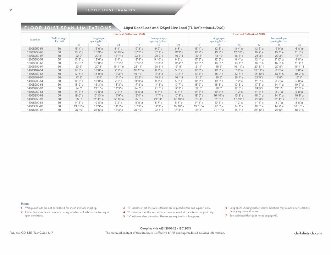
91
F L O O R J O I S T S P A N L I M I T A T I O N S
F L O O R J O I S T F R A M I N G
clarkdietrich.comPub. No. CD-STR-TechGuide 6/17 The technical content of this literature is effective 6/1/17 and supersedes all previous information.Complies with AISI S100-12 • IBC 2015
1 Web punchouts are not considered for shear and web crippling.2 Deflection checks are computed using unbalanced loads for the two equal
span conditions.
3 “e” indicates that the web stiffeners are required at the end support only.4 “i” indicates that the web stiffeners are required at the interior support only.5 “a” indicates that the web stiffeners are required at all supports.
6 Long spans utilizing shallow depth members may result in serviceability (annoying bounce) issues.
7 See additional floor joist notes on page 67.
Notes:
40psf Dead Load and 125psf Live Load (TL Deflection=L/240)
Member Yield strength Fy (ksi)
Live Load Deflection L/360 Live Load Deflection L/480Single span
spacing (in) o.c.Two equal spanspacing (in) o.c.
Single spanspacing (in) o.c.
Two equal spanspacing (in) o.c.
12 16 24 12 16 24 12 16 24 12 16 241200S250-54 50 15' 4" a 12' 6" a 8' 4" a 12' 3" a 9' 9" a 6' 8" a 15' 4" a 12' 6" a 8' 4" a 12' 3" a 9' 9" a 6' 8" a1200S250-68 50 18' 2" e 15' 9" e 12' 10" e 18' 2" a 15' 1" a 11' 3" a 18' 2" e 15' 9" e 12' 10" e 18' 2" a 15' 1" a 11' 3" a1200S250-97 50 22' 9" 20' 3" 16' 7" e 23' 5" i 20' 3" i 16' 7" i 20' 8" 18' 10" 16' 5" e 23' 3" i 20' 3" i 16' 7" i1200S300-54 50 15' 8" a 12' 6" a 8' 4" a 12' 4" a 9' 10" a 6' 8" a 15' 8" a 12' 6" a 8' 4" a 12' 4" a 9' 10" a 6' 8" a1200S300-68 50 18' 6" e 16' 0" e 13' 1" e 18' 6" a 15' 3" a 11' 4" a 18' 6" e 16' 0" e 13' 1" e 18' 6" a 15' 3" a 11' 4" a1200S300-97 50 23' 6" 20' 8" 16' 11" e 23' 11" i 20' 8" i 16' 11" i 21' 4" 19' 5" 16' 11" e 23' 11" i 20' 8" i 16' 11" i1400S162-54 50 14' 3" a 10' 8" a 7' 2" a 10' 11" a 8' 7" a 5' 8" a 14' 3" a 10' 8" a 7' 2" a 10' 11" a 8' 7" a 5' 8" a1400S162-68 50 17' 4" e 15' 0" e 12' 3" e 16' 10" i 13' 8" a 10' 2" a 17' 4" e 15' 0" e 12' 3" e 16' 10" i 13' 8" a 10' 2" a1400S162-97 50 22' 9" 19' 8" 16' 1" e 22' 9" i 19' 8" i 16' 1" i 21' 8" 19' 8" 16' 1" e 22' 9" i 19' 8" i 16' 1" i1400S200-54 50 14' 3" a 10' 8" a 7' 2" a 11' 3" a 8' 7" a 5' 8" a 14' 3" a 10' 8" a 7' 2" a 11' 3" a 8' 7" a 5' 8" a1400S200-68 50 18' 9" e 16' 3" e 13' 3" e 17' 8" a 14' 4" a 10' 7" a 18' 9" e 16' 3" e 13' 3" e 17' 8" a 14' 4" a 10' 7" a1400S200-97 50 24' 5" 21' 1" e 17' 3" e 24' 5" i 21' 1" i 17' 3" a 22' 6" 20' 6" 17' 3" e 24' 5" i 21' 1" i 17' 3" a1400S250-54 50 14' 3" a 10' 8" a 7' 2" a 11' 5" a 8' 7" a 5' 8" a 14' 3" a 10' 8" a 7' 2" a 11' 5" a 8' 7" a 5' 8" a1400S250-68 50 19' 6" e 16' 10" e 13' 9" e 18' 0" a 14' 7" a 10' 9" a 19' 6" e 16' 10" e 13' 9" e 18' 0" a 14' 7" a 10' 9" a1400S250-97 50 25' 3" 21' 11" e 17' 10" e 25' 3" i 21' 11" i 17' 10" a 23' 4" 21' 3" e 17' 10" e 25' 3" i 21' 11" i 17' 10" a1400S300-54 50 14' 3" a 10' 8" a 7' 2" a 11' 5" a 8' 7" a 5' 8" a 14' 3" a 10' 8" a 7' 2" a 11' 5" a 8' 7" a 5' 8" a1400S300-68 50 19' 11" e 17' 3" e 14' 1" e 18' 3" a 14' 9" a 10' 10" a 19' 11" e 17' 3" e 14' 1" e 18' 3" a 14' 9" a 10' 10" a1400S300-97 50 25' 10" 22' 5" e 18' 3" e 25' 10" i 22' 5" i 18' 3" a 24' 1" 21' 11" e 18' 3" e 25' 10" i 22' 5" i 18' 3" a
A L L O W A B L E W E B C R I P P L I N G L O A D S
92
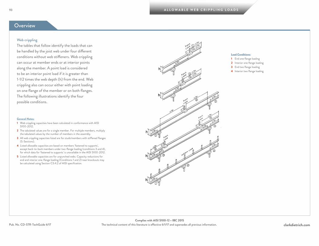
Overview
93 A L L O W A B L E W E B C R I P P L I N G L O A D S
clarkdietrich.comPub. No. CD-STR-TechGuide 6/17 The technical content of this literature is effective 6/1/17 and supersedes all previous information.Complies with AISI S100-12 • IBC 2015
Web cripplingThe tables that follow identify the loads that can be handled by the joist web under four different conditions without web stiffeners. Web crippling can occur at member ends or at interior points along the member. A point load is considered to be an interior point load if it is greater than 1-1/2 times the web depth (h) from the end. Web crippling also can occur either with point loading on one flange of the member or on both flanges. The following illustrations identify the four possible conditions.
General Notes:1 Web crippling capacities have been calculated in conformance with AISI
S100-2012. 2 The tabulated values are for a single member. For multiple members, multiply
the tabulated values by the number of members in the assembly.3 All web crippling capacities listed are for studs/members with stiffened flanges
(S-Sections).4 Listed allowable capacities are based on members 'fastened to supports',
except back-to-back members under two-flange loading (conditions 3 and 4), for which data for 'fastened to supports' is unavailable in the AISI S100-2012.
5 Listed allowable capacities are for unpunched webs. Capacity reductions for end and interior one-flange loading (Conditions 1 and 2) near knockouts may be calculated using Section C3.4.2 of AISI specification.
Load Conditions:1 End one flange loading2 Interior one flange loading3 End two flange loading4 Interior two flange loading
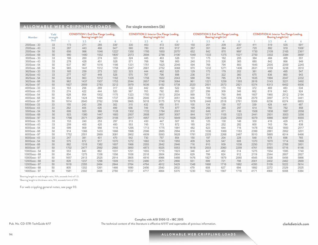
94
A L L O W A B L E W E B C R I P P L I N G L O A D S For single members (lb)
A L L O W A B L E W E B C R I P P L I N G L O A D S
clarkdietrich.comPub. No. CD-STR-TechGuide 6/17 The technical content of this literature is effective 6/1/17 and supersedes all previous information.Complies with AISI S100-12 • IBC 2015
MemberYield
strength (ksi)
CONDITION 1: End One Flange Loading, Bearing Length (in)
CONDITION 2: Interior One Flange Loading, Bearing Length (in)
CONDITION 3: End Two Flange Loading, Bearing Length (in)
CONDITION 4: Interior Two Flange Loading, Bearing Length (in)
1 3.5 4 6 1 3.5 4 6 1 3.5 4 6 1 3.5 4 6250Sxxx - 33 33 173 271 285 3361 330 453 472 5351 150 201 209 2351 411 519 535 5911
250Sxxx - 43 33 287 443 466 5471 580 780 810 9131 267 351 364 4071 720 892 918 10061
250Sxxx - 54 50 656 996 1046 12221 1350 1785 1850 20751 652 842 870 9681 1730 2109 2165 23611
250Sxxx - 68 50 990 1480 1552 18051 2073 2694 2786 31061 1049 1333 1375 15211 2750 3302 3384 36691
350Sxxx - 33 33 166 260 274 323 324 445 463 526 131 175 182 205 384 484 499 551350Sxxx - 43 33 278 428 451 528 571 768 798 900 240 315 326 365 680 842 866 949350Sxxx - 54 50 637 967 1016 1186 1331 1761 1825 2046 594 768 794 883 1645 2005 2059 2245350Sxxx - 68 50 965 1441 1512 1758 2047 2661 2752 3068 970 1232 1271 1406 2631 3159 3238 3510362Sxxx - 33 33 165 259 273 322 323 444 462 525 129 173 179 202 381 480 495 547362Sxxx - 43 33 277 427 449 526 570 767 796 898 236 311 322 360 675 836 860 943362Sxxx - 54 50 634 963 1012 1182 1329 1758 1822 2043 588 760 785 874 1635 1994 2047 2232362Sxxx - 68 50 962 1437 1507 1753 2044 2657 2748 3064 961 1221 1259 1393 2618 3143 3221 3492362Sxxx - 97 50 1827 2659 2783 3212 3979 5036 5192 5738 2020 2501 2573 2821 5374 6313 6452 6936400Sxxx - 33 33 163 256 269 317 322 442 460 522 122 164 170 192 372 469 483 534400Sxxx - 43 33 274 422 444 520 567 763 792 893 227 299 309 346 662 819 843 924400Sxxx - 54 50 628 954 1002 1170 1323 1750 1813 2034 569 735 760 846 1607 1960 2012 2194400Sxxx - 68 50 953 1424 1494 1737 2036 2646 2737 3051 936 1188 1226 1356 2579 3097 3173 3441400Sxxx - 97 50 1814 2640 2762 3189 3965 5018 5175 5718 1978 2448 2518 2761 5309 6236 6374 6853550Sxxx - 33 33 155 243 256 302 315 432 450 511 100 134 139 157 339 428 441 487550Sxxx - 43 33 262 405 426 499 556 749 778 877 195 256 265 297 614 760 782 858550Sxxx - 54 50 606 920 966 1128 1302 1722 1784 2001 502 649 671 746 1508 1838 1887 2058550Sxxx - 68 50 923 1380 1447 1683 2007 2608 2697 3007 844 1071 1105 1223 2441 2931 3003 3256550Sxxx - 97 50 1766 2571 2691 3106 3917 4957 5112 5649 1826 2261 2326 2550 5079 5966 6097 6555600Sxxx - 33 33 153 240 253 297 313 430 447 507 93 125 130 146 330 416 429 473600Sxxx - 43 33 259 400 420 493 553 745 773 872 185 243 252 282 600 743 764 838600Sxxx - 54 50 599 909 956 1116 1295 1713 1775 1991 482 623 644 716 1478 1802 1850 2017600Sxxx - 68 50 914 1366 1433 1666 1998 2596 2685 2994 816 1036 1069 1183 2399 2881 2952 3201600Sxxx - 97 50 1752 2551 2669 3081 3902 4939 5093 5628 1781 2205 2268 2487 5010 5885 6014 6466800Sxxx - 43 33 247 381 401 470 542 730 757 854 150 197 204 228 548 678 698 765800Sxxx - 54 50 575 872 917 1070 1272 1682 1743 1955 409 529 547 608 1370 1670 1714 1869800Sxxx - 68 50 882 1318 1382 1607 1966 2555 2642 2946 716 910 939 1038 2250 2701 2768 3001800Sxxx - 97 50 1702 2477 2592 2992 3850 4873 5025 5553 1618 2003 2060 2259 4761 5593 5716 61461000Sxxx - 54 50 553 840 882 1031 1251 1655 1715 1923 346 447 462 514 1275 1554 1595 17401000Sxxx - 68 50 854 1275 1338 1556 1938 2518 2604 2904 629 799 824 912 2119 2544 2607 28271000Sxxx - 97 50 1657 2413 2525 2914 3805 4816 4966 5488 1476 1827 1879 2060 4545 5338 5456 58661200Sxxx - 68 50 828 1237 1298 1509 1913 2486 2571 2866 551 699 721 798 2001 2402 2462 26691200Sxxx - 97 50 1618 2355 2464 2844 3764 4764 4912 5429 1348 1668 1716 1882 4350 5109 5222 56141400Sxxx - 68 50 805 1202 1261 1466 1890 2456 2540 2832 479 608 627 694 1892 2272 2329 25251400Sxxx - 97 50 1581 2302 2408 2780 3727 4717 4864 5375 1230 1523 1567 1718 4171 4900 5008 5384
1Bearing length to web height ratio, N/h, exceeds limit of 1.0.2Bearing length to thickness ratio, N/t, exceeds limit of 210.
For web crippling general notes, see page 93.
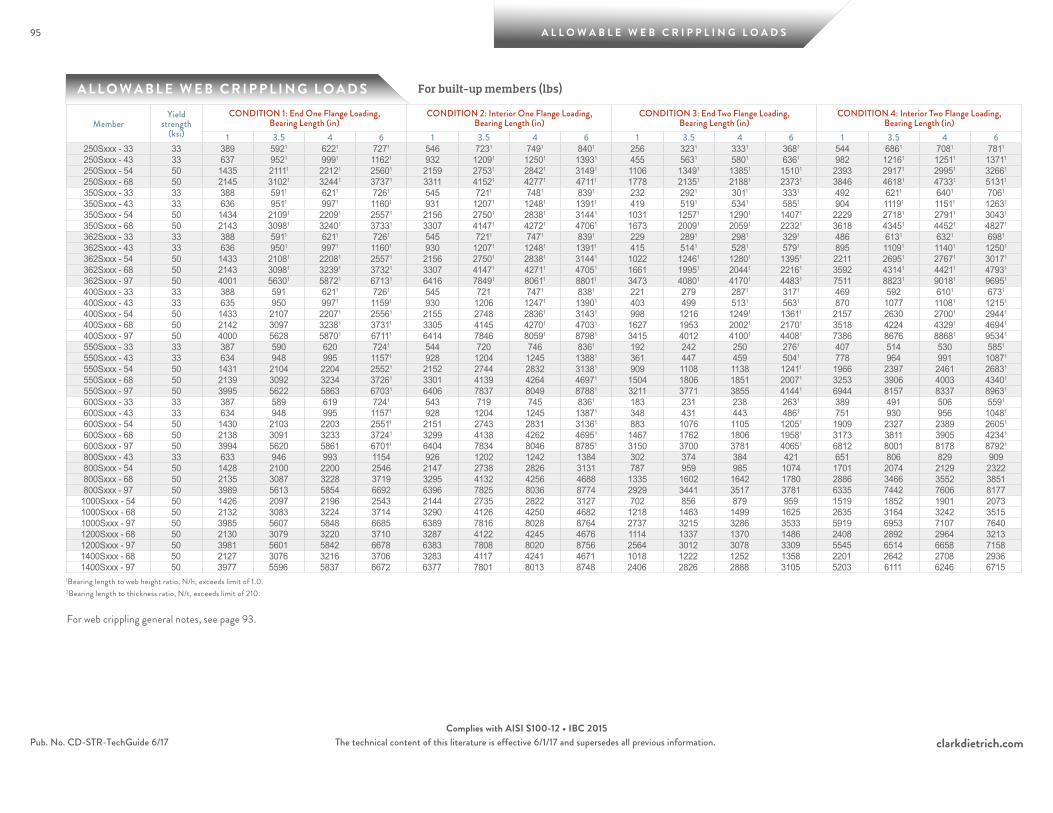
95
A L L O W A B L E W E B C R I P P L I N G L O A D S
A L L O W A B L E W E B C R I P P L I N G L O A D S
clarkdietrich.comPub. No. CD-STR-TechGuide 6/17 The technical content of this literature is effective 6/1/17 and supersedes all previous information.Complies with AISI S100-12 • IBC 2015
For built-up members (lbs)
MemberYield
strength (ksi)
CONDITION 1: End One Flange Loading, Bearing Length (in)
CONDITION 2: Interior One Flange Loading, Bearing Length (in)
CONDITION 3: End Two Flange Loading, Bearing Length (in)
CONDITION 4: Interior Two Flange Loading, Bearing Length (in)
1 3.5 4 6 1 3.5 4 6 1 3.5 4 6 1 3.5 4 6250Sxxx - 33 33 389 5921 6221 7271 546 7231 7491 8401 256 3231 3331 3681 544 6861 7081 7811
250Sxxx - 43 33 637 9521 9991 11621 932 12091 12501 13931 455 5631 5801 6361 982 12161 12511 13711
250Sxxx - 54 50 1435 21111 22121 25601 2159 27531 28421 31491 1106 13491 13851 15101 2393 29171 29951 32661
250Sxxx - 68 50 2145 31021 32441 37371 3311 41521 42771 47111 1778 21351 21881 23731 3846 46181 47331 51311
350Sxxx - 33 33 388 5911 6211 7261 545 7211 7481 8391 232 2921 3011 3331 492 6211 6401 7061
350Sxxx - 43 33 636 9511 9971 11601 931 12071 12481 13911 419 5191 5341 5851 904 11191 11511 12631
350Sxxx - 54 50 1434 21091 22091 25571 2156 27501 28381 31441 1031 12571 12901 14071 2229 27181 27911 30431
350Sxxx - 68 50 2143 30981 32401 37331 3307 41471 42721 47061 1673 20091 20591 22321 3618 43451 44521 48271
362Sxxx - 33 33 388 5911 6211 7261 545 7211 7471 8391 229 2891 2981 3291 486 6131 6321 6981
362Sxxx - 43 33 636 9501 9971 11601 930 12071 12481 13911 415 5141 5281 5791 895 11091 11401 12501
362Sxxx - 54 50 1433 21081 22081 25571 2156 27501 28381 31441 1022 12461 12801 13951 2211 26951 27671 30171
362Sxxx - 68 50 2143 30981 32391 37321 3307 41471 42711 47051 1661 19951 20441 22161 3592 43141 44211 47931
362Sxxx - 97 50 4001 56301 58721 67131 6416 78491 80611 88011 3473 40801 41701 44831 7511 88231 90181 96951
400Sxxx - 33 33 388 591 6211 7261 545 721 7471 8381 221 279 2871 3171 469 592 6101 6731
400Sxxx - 43 33 635 950 9971 11591 930 1206 12471 13901 403 499 5131 5631 870 1077 11081 12151
400Sxxx - 54 50 1433 2107 22071 25561 2155 2748 28361 31431 998 1216 12491 13611 2157 2630 27001 29441
400Sxxx - 68 50 2142 3097 32381 37311 3305 4145 42701 47031 1627 1953 20021 21701 3518 4224 43291 46941
400Sxxx - 97 50 4000 5628 58701 67111 6414 7846 80591 87981 3415 4012 41001 44081 7386 8676 88681 95341
550Sxxx - 33 33 387 590 620 7241 544 720 746 8361 192 242 250 2761 407 514 530 5851
550Sxxx - 43 33 634 948 995 11571 928 1204 1245 13881 361 447 459 5041 778 964 991 10871
550Sxxx - 54 50 1431 2104 2204 25521 2152 2744 2832 31381 909 1108 1138 12411 1966 2397 2461 26831
550Sxxx - 68 50 2139 3092 3234 37261 3301 4139 4264 46971 1504 1806 1851 20071 3253 3906 4003 43401
550Sxxx - 97 50 3995 5622 5863 67031 6406 7837 8049 87881 3211 3771 3855 41441 6944 8157 8337 89631
600Sxxx - 33 33 387 589 619 7241 543 719 745 8361 183 231 238 2631 389 491 506 5591
600Sxxx - 43 33 634 948 995 11571 928 1204 1245 13871 348 431 443 4861 751 930 956 10481
600Sxxx - 54 50 1430 2103 2203 25511 2151 2743 2831 31361 883 1076 1105 12051 1909 2327 2389 26051
600Sxxx - 68 50 2138 3091 3233 37241 3299 4138 4262 46951 1467 1762 1806 19581 3173 3811 3905 42341
600Sxxx - 97 50 3994 5620 5861 67011 6404 7834 8046 87851 3150 3700 3781 40651 6812 8001 8178 87921
800Sxxx - 43 33 633 946 993 1154 926 1202 1242 1384 302 374 384 421 651 806 829 909800Sxxx - 54 50 1428 2100 2200 2546 2147 2738 2826 3131 787 959 985 1074 1701 2074 2129 2322800Sxxx - 68 50 2135 3087 3228 3719 3295 4132 4256 4688 1335 1602 1642 1780 2886 3466 3552 3851800Sxxx - 97 50 3989 5613 5854 6692 6396 7825 8036 8774 2929 3441 3517 3781 6335 7442 7606 81771000Sxxx - 54 50 1426 2097 2196 2543 2144 2735 2822 3127 702 856 879 959 1519 1852 1901 20731000Sxxx - 68 50 2132 3083 3224 3714 3290 4126 4250 4682 1218 1463 1499 1625 2635 3164 3242 35151000Sxxx - 97 50 3985 5607 5848 6685 6389 7816 8028 8764 2737 3215 3286 3533 5919 6953 7107 76401200Sxxx - 68 50 2130 3079 3220 3710 3287 4122 4245 4676 1114 1337 1370 1486 2408 2892 2964 32131200Sxxx - 97 50 3981 5601 5842 6678 6383 7808 8020 8756 2564 3012 3078 3309 5545 6514 6658 71581400Sxxx - 68 50 2127 3076 3216 3706 3283 4117 4241 4671 1018 1222 1252 1358 2201 2642 2708 29361400Sxxx - 97 50 3977 5596 5837 6672 6377 7801 8013 8748 2406 2826 2888 3105 5203 6111 6246 6715
1Bearing length to web height ratio, N/h, exceeds limit of 1.0.2Bearing length to thickness ratio, N/t, exceeds limit of 210.
For web crippling general notes, see page 93.
R E F E R E N C E
96
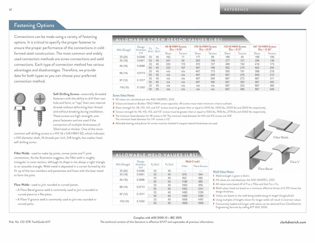
Fastening Options
97 R E F E R E N C E
clarkdietrich.comPub. No. CD-STR-TechGuide 6/17 The technical content of this literature is effective 6/1/17 and supersedes all previous information.Complies with AISI S100-12 • IBC 2015
Fillet Welds
Flare V
Flare Bevel
Connections can be made using a variety of fastening options. It is critical to specify the proper fastener to ensure the proper performance of the connections in cold-formed steel construction. The most common and widely used connection methods are screw connections and weld connections. Each type of connection method has various advantages and disadvantages. Therefore, we provide data for both types so you can choose your preferred connection method.
Weld Value Notes:1 Weld strength is given in lbs/in.2 All values are calculated per the AISI-NASPEC, 2012. 3 All values were based off of Fxx > 70ksi and that Fxx > Fu.4 Weld values listed are based on a minimum effective throat of 0.707 times the
design thickness.5 Values are based on the weld being loaded along its length (longitudinal).6 Using multiples of lengths shown for longer welds will result in incorrect values.7 Transversely loaded and longer weld values can be obtained from ClarkDietrich
Engineering Services by calling 877-832-3206.
Fillet Welds—used to make lap joints, corner joints and T-joint connections. As the illustration suggests, the fillet weld is roughly triangular in cross-section, although its shape is not always a right triangle or an isosceles triangle. Weld metal is deposited in a corner formed by the fit-up of the two members and penetrates and fuses with the base metal to form the joint.
Flare Welds—used to join rounded or curved pieces. • A Flare Bevel groove weld is commonly used to join a rounded or curved piece to a flat piece. • A Flare V groove weld is commonly used to join two rounded or curved parts.
Screw Value Notes:1 All values are calculated per the AISI-NASPEC, 2012. 2 Values are based on Buildex TEK2 HWH screw capacities. All screws must meet minimum criteria outlined.3 Shear strength for #8, #10, #12, and 1/4" screws must be greater than or equal to 1000 lbs, 1400 lbs, 2000 lbs and 2600 lbs respectively.4 Tension strength for #8, #10, #12, and 1/4" screws must be greater than or equal to 1545 lbs, 1936 lbs, 2778 lbs and 4060 lbs respectively.5 The minimum head diameter for #8 screws is 1/4." The minimum head diameter for #10 and #12 screws are 3/8."
The minimum head diameter for 1/4" screws is 1/2."6 Allowable bearing and pullover for screws must be checked if unequal material thicknesses are used.
Mils (Gauge)Design
thickness (in)
Fy (ksi)
Fu (ksi)
#8-18 HWH Screws Dia. = 0.16"
#10-16 HWH Screws Dia. = 0.19"
#12-14 HWH Screws Dia. = 0.21"
1/4"-14 HWH Screws Dia. = 0.24"
Shear Tension Shear Tension Shear Tension Shear Tension33 (20) 0.0346 33 45 162 71 177 84 186 93 199 10643 (18) 0.0451 33 45 241 92 263 109 277 121 296 138
54 (16) 0.0566 33 45 333 115 370 137 389 152 416 17350 65 333 167 467 198 562 219 600 250
68 (14) 0.0713 33 45 n/a n/a 467 173 550 191 588 21850 65 n/a n/a 467 249 667 276 849 315
97 (12) 0.1017 33 45 n/a n/a 467 246 667 272 867 31150 65 n/a n/a 467 356 667 393 867 450
118 (10) 0.1242 33 45 n/a n/a n/a n/a 667 333 867 38050 65 n/a n/a n/a n/a 667 480 867 549
Mils (Gauge)Design
thickness (in)
Fy (ksi) Fu (ksi)Weld (1 inch)
Fillet Flare Groove33 (20) 0.0346 33 45 — —43 (18) 0.0451 33 45 619 544
54 (16) 0.0566 33 45 822 68250 65 1188 985
68 (14) 0.0713 33 45 1082 85950 65 1563 1241
97 (12) 0.1017 33 45 1480 122650 65 1480 1480
118 (10) 0.1242 33 45 1808 149750 65 1808 1808
A L L O W A B L E S C R E W D E S I G N V A L U E S ( L B S )
Self-Drilling Screws—externally threaded fasteners with the ability to drill their own hole and form, or “tap,” their own internal threads without deforming their thread and without breaking during installation. These screws are high-strength, one-piece fasteners and are used if the connection of multiple thicknesses of 33mil steel or thicker. One of the more
common self-drilling screws is a #10-16 x 5/8 HWH SD, which indicates a #10 diameter shaft, 16 threads per inch, 5/8 length, hex washer head self-drilling screw.
A L L O W A B L E W E L D V A L U E S ( L B S )
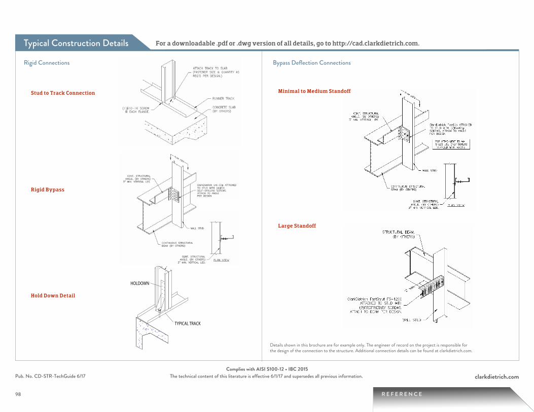
Typical Construction Details
98 R E F E R E N C E
clarkdietrich.comPub. No. CD-STR-TechGuide 6/17 The technical content of this literature is effective 6/1/17 and supersedes all previous information.Complies with AISI S100-12 • IBC 2015
For a downloadable .pdf or .dwg version of all details, go to http://cad.clarkdietrich.com.
TYPICAL Construction Details
Rigid Connections
Large Standoff
Minimal to Medium Standoff
By-Pass Deflection Connections
Hold Down Detail
Stud to Track Connection
Rigid Bypass
STRL
TYPICAL STUD
DIETRICH FCSC-3.5
PLAN VIEW
1" GAP(MAX)
PLAN VIEWSTRL ANGLE
TYPICAL STUD
DIETRICH UNICLIP USEC
PLAN VIEW
1" (MAX)OFFSET
PLAN VIEW
TYPICALWALL STUD
2" MIN.
DIETRICH FastStrut FS-1200
STRUCTURAL BEAM
HOLDOWN
SHEARWALL CHORD STUD
TYPICAL TRACK
INSTALL STUDS WITH SAME
DIMENSION FOR BRIDGING ALIGNMENT
SCREW(S) ON EACH SIDE OF STUD
Rigid Connections Bypass Deflection Connections
Stud to Track Connection Minimal to Medium Standoff
Rigid Bypass
Large Standoff
Hold Down Detail
Details shown in this brochure are for example only. The engineer of record on the project is responsible for the design of the connection to the structure. Additional connection details can be found at clarkdietrich.com.
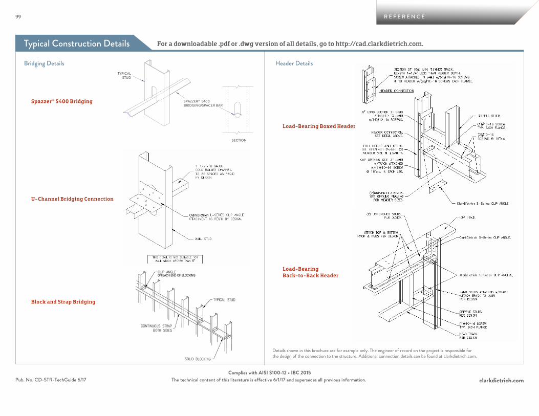
Typical Construction Details For a downloadable .pdf or .dwg version of all details, go to http://cad.clarkdietrich.com.
99 R E F E R E N C E
clarkdietrich.comPub. No. CD-STR-TechGuide 6/17 The technical content of this literature is effective 6/1/17 and supersedes all previous information.Complies with AISI S100-12 • IBC 2015
SECTION
SPAZZER® 5400BRIDGING/SPACER BAR
TYPICALSTUD
CLIP ANGLE
U-CHANNEL
TYPICAL STUD
CRIPPLE STUDSABOVE OPENING
HDS CLIP FASTENED TO JAMB
HDS JAMB
HDS HEADER
BOXED HEADER
JAMB
TRACK PIECE
SUPPORT CLIP
Bridging Details Header Details
Spazzer® 5400 Bridging
Load-Bearing Boxed Header
U-Channel Bridging Connection
Block and Strap Bridging
Load-Bearing Back-to-Back Header
Details shown in this brochure are for example only. The engineer of record on the project is responsible for the design of the connection to the structure. Additional connection details can be found at clarkdietrich.com.
ON EACH END OF BLOCKING
6"
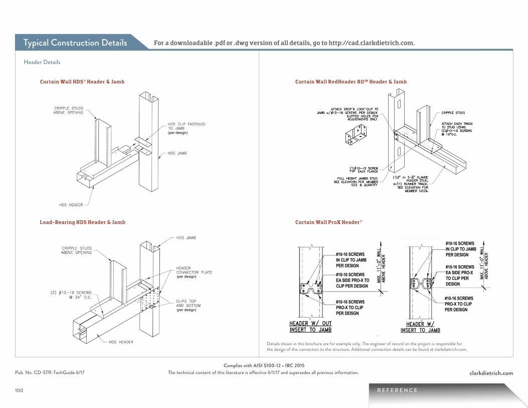
Typical Construction Details For a downloadable .pdf or .dwg version of all details, go to http://cad.clarkdietrich.com.
100 R E F E R E N C E
clarkdietrich.comPub. No. CD-STR-TechGuide 6/17 The technical content of this literature is effective 6/1/17 and supersedes all previous information.Complies with AISI S100-12 • IBC 2015
Curtain Wall HDS® Header & Jamb Curtain Wall RedHeader RO™ Header & Jamb
Load-Bearing HDS Header & Jamb Curtain Wall ProX Header®ProX
Hea
der®
Fra
min
g Sy
stem
The Brady ProX Header System has undergone stringent laboratory testing. ProX complies with all industry standard Light Gauge Metal Stud Framing ASTM criteria. Section geometry and material strengths were modeled in CFS Version 4.1, a cold-formed steel design and analysis software. Calculated in accordance 2001 addition of the American Iron and Steel Institute (AISI) Specifications for Design of Cold Formed Structural Members.
Dietrich / ProX SSMA Nomenclature Put the ProX Header System to work on your next project.
Brady ProX has become an industry standard for all wall openings.The ProX is ideal for all types of door, window, shaftwall, HVAC, and ventilation openings. This simple system has application to a wide range of openings and can carry greater loads with less steel. The contractor community prefers the ProX system over traditional built-up headers.
Typical Interior Wall Openings
on
r
Double DoorSingle Door
ProX Clip - Available Only in 16 gauge (54 mil.) 50 ksi material Patent Number 6,799,408 & 7,178,304
362 X 425 3.625” 92.1 4.25” 107.95 362 XT 162 3.464” 88 1.625” 41.3 362Clip-54 1.50” 38.1
400 X 425 4.000” 101.6 4.25” 107.95 400 XT 162 3.839” 97.5 1.625” 41.3 400Clip-54 1.50” 38.1
600 X 425 6.000” 152.4 4.25” 107.95 600 XT 162 5.839” 148.3 1.625” 41.3 600Clip-54 1.50” 38.1
800 X 425 8.000” 203.2 4.25” 107.95 800 XT 162 7.839” 199.1 1.625” 41.3 800Clip-54 1.50” 38.1
Member Types and Available Sizes
WidthProX Header (Outer Member) - OD ProX Insert (Insert Member) - OD
inches (mm) inches (mm)inches (mm) inches (mm) inches (mm)Height Width Height Leg Length
ProX Clip*Member Type Member Type Member Type
®
Building a Better Way.
Member Types and Available Sizes
Detail Dimensions
7.8395.8393.8393.4641.899
1.8993.6254.0006.0008.000
1.625
4.25
Single Piece Header
Header InsertOptional
Two Piece Header
Internal Connection Clip
SSMA - 400X425-33 SSMA - 400XT162-33 SSMA - 400XTC425-33 SSMA - 400Clip-150-54 Dietrich - 400PXH-33 Dietrich - 400PXT-33 Dietrich - Order by Piece Dietrich - 400XTC-54
Header Details
Details shown in this brochure are for example only. The engineer of record on the project is responsible for the design of the connection to the structure. Additional connection details can be found at clarkdietrich.com.
#10-16 SCREWS IN CLIP TO JAMB PER DESIGN
#10-16 SCREWS EA SIDE PRO-X TO CLIP PER DESIGN
#10-16 SCREWS PRO-X TO CLIPPER DEISGN
#10-16 SCREWS IN CLIP TO JAMB PER DESIGN
#10-16 SCREWS EA SIDE PRO-X TO CLIP PER DESIGN
#10-16 SCREWS PRO-X TO CLIPPER DEISGN
(per design)
(per design)
(per design)
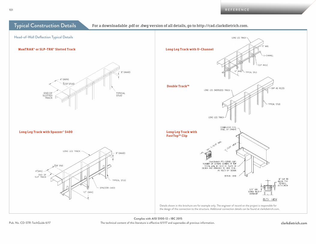
Typical Construction Details For a downloadable .pdf or .dwg version of all details, go to http://cad.clarkdietrich.com.
101 R E F E R E N C E
clarkdietrich.comPub. No. CD-STR-TechGuide 6/17 The technical content of this literature is effective 6/1/17 and supersedes all previous information.Complies with AISI S100-12 • IBC 2015
12" MAX
"X" (MAX)
U-CHANNEL
CLIP ANGLE
TYPICAL STUD
LONG LEG TRACK
GAP AS REQ'D
TYPICAL STUD
DEEP LEGSTANDARD
TRACK
OVERSIZED SLIP TRACK
CONTINUOUS STRL. STEEL
TYPICAL STUD
CLARKDIETRICH FTC
3/4" MIN.SCREW EDGE
DISTANCE
X" GAP TOALLOW FOR
VERTICALDEFLECTION
ELEV. VIEW
ENGINEER OF RECORD:VERIFY GAP DEPTH.
ELEV. VIEW
CA
B
END OFSLOTTED
TRACK
4" (MIN)
TYPICAL STUD
SLOTTEDTRACK
X" (MAX)
TYPICAL STUD
X" (MAX)
C OF STUD
WALL INSIDE EDGE OF SLABSPAZZER® 5400
TYPICAL STUD
END OFLONG LEG
4"(MIN)
12" (MAX)
X" (MAX)
C
X" (MAX)
A
TYPICAL STUD
LONG LEGTRACK
B
COF STUD
WALL OUTSIDE EDGE OF BEAM
L
Head-of-Wall Deflection Typical Details
MaxTRAK® or SLP-TRK® Slotted Track
Long Leg Track with Spazzer® 5400
Long Leg Track with U-Channel
Long Leg Track with FastTop™ Clip
Double Track™
Details shown in this brochure are for example only. The engineer of record on the project is responsible for the design of the connection to the structure. Additional connection details can be found at clarkdietrich.com.
12" MAX
"X" (MAX)
U-CHANNEL
CLIP ANGLE
TYPICAL STUD
LONG LEG TRACK
GAP AS REQ'D
TYPICAL STUD
DEEP LEGSTANDARD
TRACK
OVERSIZED SLIP TRACK
CONTINUOUS STRL. STEEL
TYPICAL STUD
CLARKDIETRICH FTC
3/4" MIN.SCREW EDGE
DISTANCE
X" GAP TOALLOW FOR
VERTICALDEFLECTION
ELEV. VIEW
ENGINEER OF RECORD:VERIFY GAP DEPTH.
ELEV. VIEW
CA
B
END OFSLOTTED
TRACK
4" (MIN)
TYPICAL STUD
SLOTTEDTRACK
X" (MAX)
TYPICAL STUD
X" (MAX)
C OF STUD
WALL INSIDE EDGE OF SLABSPAZZER® 5400
TYPICAL STUD
END OFLONG LEG
4"(MIN)
12" (MAX)
X" (MAX)
C
X" (MAX)
A
TYPICAL STUD
LONG LEGTRACK
B
COF STUD
WALL OUTSIDE EDGE OF BEAM
L
X
Support Tools
102 R E F E R E N C E
clarkdietrich.comPub. No. CD-STR-TechGuide 6/17 The technical content of this literature is effective 6/1/17 and supersedes all previous information.
clarkdietrich.com Visit to explore company information, design tools, technical documents, services and so much more. Featuring a unique product selector, our website is designed to deliver the details you want with a minimum number of clicks.
SubmittalPro®
We built this online technical submittal generator tool to make your job easier. Use it to quickly view data on our products and create your final submittal documents. Access SubmittalPro at clarkdietrich.com or on your desktop or smartphone.
iTools.clarkdietrich.comGoing mobile? With your smartphone in hand, you can perform a fast, easy search, view ProSTUD limiting heights and even email submittal documents.
Architectural Specification ReviewOver time, project specifications can become outdated. For suggestions on how to improve the performance of your specifications, contact us about a complimentary review at 330-974-0835..
Technical ServicesCount on ClarkDietrich Technical Services to respond to a variety of needs, from general questions on industry standards to specifics on accurate sizing. Call us at 888-437-3244.
103 R E F E R E N C E
clarkdietrich.comPub. No. CD-STR-TechGuide 6/17 The technical content of this literature is effective 6/1/17 and supersedes all previous information.
ClarkDietrich LEED® Information and Requirements
LEED® Services BUILD GREEN with ClarkDietrich Building Systems ClarkDietrich Building Systems is an active member of the U.S. Green Building Council and is committed to supplying quality products that are environmentally responsible. We are continually working to develop greener building products and sustainable business practices. ClarkDietrich steel framing helps contribute points toward LEED® certification. For more details contact Technical Services at 888-437-3244 or visit www.clarkdietrich.com/LEED.
ClarkDietrich plant locations:
ClarkDietrich Building Systems ClarkDietrich Building Systems, Inc. is an active member of the U.S. Green Building Council with LEED® Accredited Professionals on staff. ClarkDietrich is committed to supplying quality products and continually looking for new ways to develop greener building products and sustainable business practices. In total, ClarkDietrich products can help your project qualify for up to 7 LEED Credits under LEED for New Construction and Major Renovations (LEED-NC Ver. 2.2 and 3.0).
Riverside, CASacramento, CABristol, CT
Dade City, FLMcDonough, GAKapolei, HI
Rochelle, ILBaltimore, MDVienna, OH
Baytown, TX Dallas, TX
ClarkDietrich LEED Request Form online at clarkdietrich.com
*USGBC and its related logo are trademarks owned by the U.S. Green Building Council and are used by permission.

Structural framing standardsAISI S100-12 “North American Specification for the Design of Cold-Formed Steel Structural Members
ASTM C955 Load-bearing steel framingASTM C1007 Installation ASTM A1003 Material specification for steel sheet
Protective coating standardsASTM A653 Zinc-coated hot-dip processASTM A792 55% aluminum-zinc alloy-coated
hot-dip processASTM A875 Zinc-5% aluminum alloy-coated
hot-dip processASTM A924 Metallic-coated hot-dip process
Additional code approvalsSFIA (Steel Framing Industry Association)Intertek CCRR 0206
ProSTUD® drywall framing standardsAISI S100 2012 “North American Specification for the Design of Cold-Formed Steel Structural Members”
ASTM American Society for Testing and MaterialsA653 Zinc-coated hot-dip processA1003 Material specification for steel sheet C645 Standard specification for nonstructural steel framing C754 Standard specification for installation of steel framing C1002 Standard specification for steel self piercing
tapping screwE119 Standard test methods for fire tests E72 Standard test methods of conducting strength tests E90 Standard test method for sound transmission loss
UL® Underwriters Laboratories testing standardUL 263 Fire Tests of Building Construction and Materials
Multiple UL® design listings for ProSTUDOver 50 UL Designs; UL file number R26512
Additional code approvalsIntertek CCRR 0207
UL® and UL® Design are trademarks of Underwriters Laboratories, Inc.
Metal lath & accessoriesASTM C847 Metal lathASTM C841 Installation of interior lathing & furringASTM C1063 Installation of lathing & furringASTM A653 Zinc-coated hot-dip processASTM C1047 Accessories standards—control jointsASTM A924 Metallic-coated hot-dip processUUB790A APB type 1, grade D, style 2CE 240.01 Furring (metal) lathing and plasteringEMLA 920 Guide specs for metal lathing & furring
Additional code approvalsIntertek CCRR 0204
ClarkDietrich Building Systems has prepared this literature with the utmost diligence and care for accuracy and conformance to standards.
ClarkDietrich Building Systems reserves the right to modify or change any information contained in this literature without notification.
ClarkDietrich Building Systems intends this information to be accurate, informative, and helpful as a selection guide for choosing ClarkDietrich Building System products. However, this information is only to be used for guidance and is not intended to replace the design, drawings, specifications, and decisions of a professional architect or engineer.
ClarkDietrich Building Systems or its affiliates shall not be responsible for incidental or consequential damages, directly or indirectly sustained, nor for loss caused by application of our products for other than their intended uses. Our liability is limited to replacement of defective products. Claims shall be deemed waived unless they are made to us in writing within thirty (30) days of the date a problem was or reasonably should have been discovered.
ClarkDietrich Building Systems Manufacturing and Sales Locations:
ClarkDietrich Engineering Services. A full spectrum of solutions.Toll-Free Phone: 877.832.3206 Toll-Free Fax: 877.832.3208Technical Services: 888.437.3244Email: [email protected]
CALIFORNIA Riverside P 951.360.3500
CALIFORNIA Sacramento P 951.360.3500
CONNECTICUT Bristol P 866.921.0023
FLORIDA Dade CityP 352.518.4400
VINYL CORP. P 800.648.4695
L O C A T I O N S
GEORGIA McDonough P 678.304.5500
HAWAII Kapolei P 951.360.3500
ILLINOIS RochelleP 800.659.0745
MARYLAND BaltimoreP 410.477.4000
OHIO Warren-East P 330.372.5564
OHIO Vienna P 330.372.4014
TEXAS Baytown P 281.383.1617
TEXAS Dallas P 214.350.1716
USGBC and related logo is a trademark owned by the U.S. Green Building Council and is used by permission.
CENTRAL Crown Point, IN
NORTHEAST Bristol, CT
SOUTHEAST McDonough, GA
WEST Carlsbad, CA
104 R E F E R E N C E
clarkdietrich.comPub. No. CD-STR-TechGuide 6/17 The technical content of this literature is effective 6/1/17 and supersedes all previous information.Complies with AISI S100-12 • IBC 2015
Scan for the most up-to-date ClarkDietrich literature.
ClarkDietrich structural and nonstructural framing comply with the SFIA Code Compliance Program. ClarkDietrich is a member of SFIA.
Check the updated list of Certified Production Facilities at Architectural Testing’s website at www.archtest.com.
Typical Construction DetailsClarkDietrich Material Certification—Code Approvals and Performance

CD-STR-TechGuide © 6/17 ClarkDietrich Building Systems • The technical content of this literature is effective 6/1/17 and supersedes all previous information.
Turn to ClarkDietrich for a complete lineup of steel construction products and services nationwide:
Interior Framing∙Exterior Framing∙Interior Finishing∙Clips/Connections∙Metal Lath/Accessories∙Engineering
9050 Centre Pointe Dr. Suite 400 West Chester, OH 45069
P 513.870.1100 F 513.870.1300
clarkdietrich.comClarkwestern Dietrich Building Systems LLC
FPO
Top Related