![[STEEL Structure] Design Guide for Cold-Formed Steel Beams With Web Penetration - AISI - US 0906](https://static.fdocuments.us/doc/165x107/55cfea4e5503467d968bd1bc/steel-structure-design-guide-for-cold-formed-steel-beams-with-web-penetration.jpg)
[STEEL Structure] Design Guide for Cold-Formed Steel Beams With Web Penetration - AISI - US 0906
10/21/2016
1
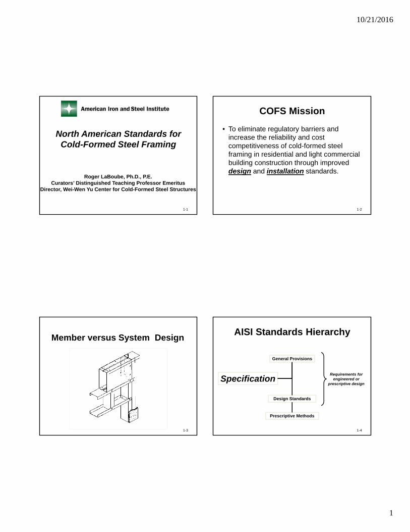
North American Standards for Cold-Formed Steel Framing
1-1
Roger LaBoube, Ph.D., P.E.Curators’ Distinguished Teaching Professor Emeritus
Director, Wei-Wen Yu Center for Cold-Formed Steel Structures
COFS Mission
• To eliminate regulatory barriers and increase the reliability and cost competitiveness of cold-formed steel framing in residential and light commercial building construction through improved design and installation standards.
1-2
Member versus System Design
1-3
Design Standards
Prescriptive Methods
Requirements for engineered or
prescriptive designSpecification
General Provisions
AISI Standards Hierarchy
1-4
10/21/2016
2
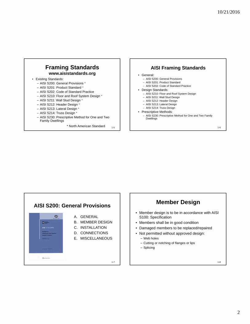
Framing Standardswww.aisistandards.org
• Existing Standards:– AISI S200: General Provisions *– AISI S201: Product Standard *– AISI S202: Code of Standard Practice– AISI S210: Floor and Roof System Design *– AISI S211: Wall Stud Design *– AISI S212: Header Design *– AISI S213: Lateral Design *– AISI S214: Truss Design *– AISI S230: Prescriptive Method for One and Two
Family Dwellings
1-5* North American Standard
AISI Framing Standards• General:
– AISI S200: General Provisions– AISI S201: Product Standard– AISI S202: Code of Standard Practice
• Design Standards:– AISI S210: Floor and Roof System Design– AISI S211: Wall Stud Design– AISI S212: Header Design– AISI S213: Lateral Design– AISI S214: Truss Design
• Prescriptive Methods:– AISI S230: Prescriptive Method for One and Two Family
Dwellings
1-6
AISI S200: General Provisions
A. GENERAL
B. MEMBER DESIGN
C. INSTALLATION
D. CONNECTIONS
E. MISCELLANEOUS
1-7
Member Design
• Member design is to be in accordance with AISI S100: Specification
• Members shall be in good condition
• Damaged members to be replaced/repaired
• Not permitted without approved design:– Web holes
– Cutting or notching of flanges or lips
– Splicing
1-8
10/21/2016
3
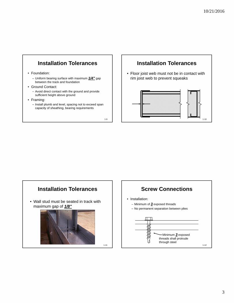
Installation Tolerances
• Foundation:
– Uniform bearing surface with maximum 1/4” gap between the track and foundation
• Ground Contact:– Avoid direct contact with the ground and provide
sufficient height above ground
• Framing:– Install plumb and level, spacing not to exceed span
capacity of sheathing, bearing requirements
1-9
Installation Tolerances
• Floor joist web must not be in contact with rim joist web to prevent squeaks
1-10
Installation Tolerances
• Wall stud must be seated in track with maximum gap of 1/8”
1-11
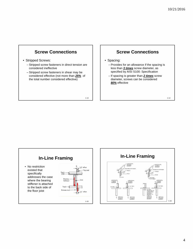
Screw Connections
• Installation:
– Minimum of 3 exposed threads
– No permanent separation between plies
1-12
Minimum 3 exposed threads shall protrude through steel
10/21/2016
4
Screw Connections
• Stripped Screws:– Stripped screw fasteners in direct tension are
considered ineffective
– Stripped screw fasteners in shear may be considered effective (not more than 25% of the total number considered effective)
1-13
Screw Connections
• Spacing:– Provides for an allowance if the spacing is
less than 3 times screw diameter, as specified by AISI S100: Specification
– If spacing is greater than 2 times screw diameter, screws can be considered 80% effective
1-14
In-Line Framing
• No restriction existed that specifically addresses the case where the bearing stiffener is attached to the back side of the floor joist
1-15
In-Line Framing
1-16
10/21/2016
5
AISI S201: Product Data
A. GENERAL
B. MATERIALS
C. PRODUCTS
D. QUALITY ASSURANCE
1-17
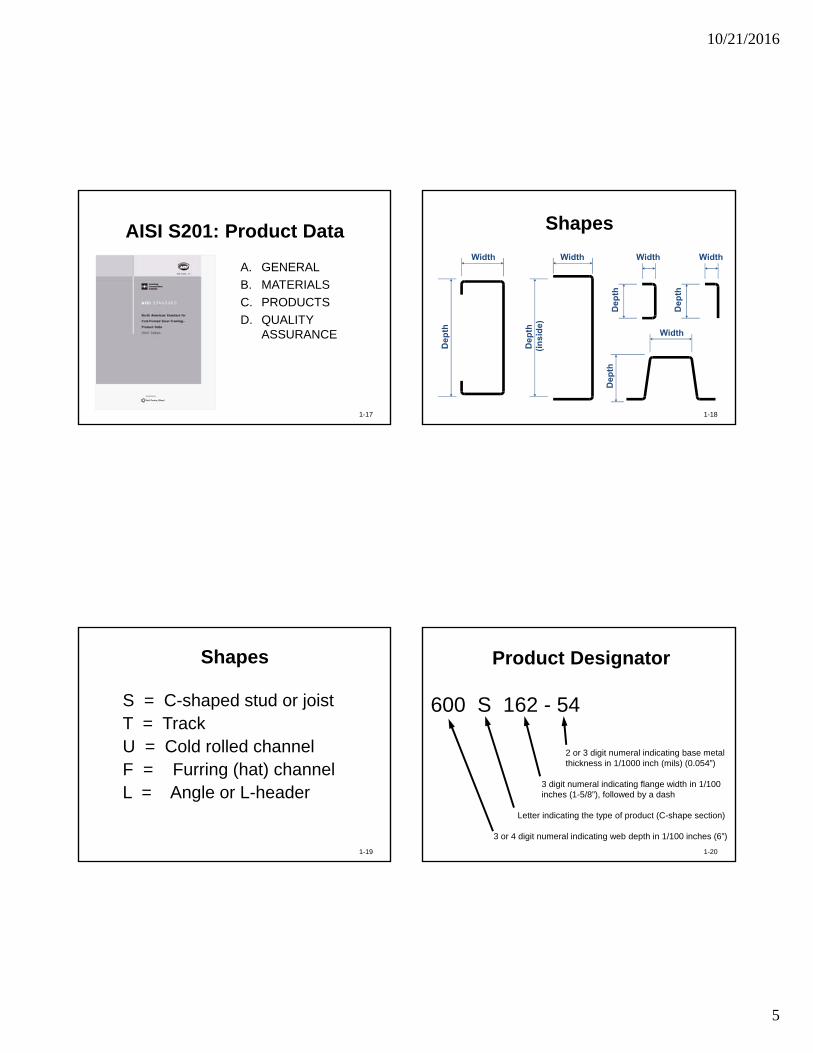
Shapes
1-18
Shapes
S = C-shaped stud or joistT = TrackU = Cold rolled channelF = Furring (hat) channelL = Angle or L-header
1-19
2 or 3 digit numeral indicating base metalthickness in 1/1000 inch (mils) (0.054”)
3 digit numeral indicating flange width in 1/100 inches (1-5/8”), followed by a dash
Letter indicating the type of product (C-shape section)
3 or 4 digit numeral indicating web depth in 1/100 inches (6”)
600 S 162 - 54
Product Designator
1-20
10/21/2016
6
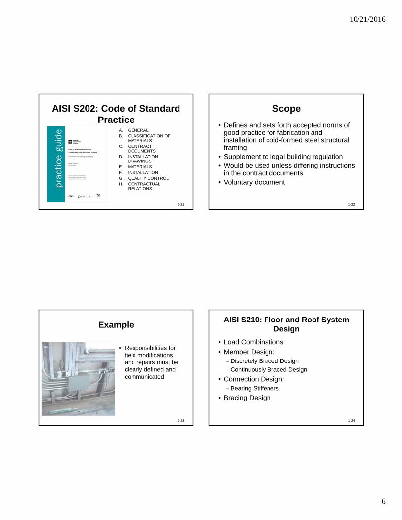
AISI S202: Code of Standard Practice
A. GENERALB. CLASSIFICATION OF
MATERIALSC. CONTRACT
DOCUMENTSD. INSTALLATION
DRAWINGSE. MATERIALSF. INSTALLATIONG. QUALITY CONTROLH. CONTRACTUAL
RELATIONS
1-21
Scope
• Defines and sets forth accepted norms of good practice for fabrication and installation of cold-formed steel structural framing
• Supplement to legal building regulation• Would be used unless differing instructions
in the contract documents• Voluntary document
1-22
Example
1-23
• Responsibilities for field modifications and repairs must be clearly defined and communicated
AISI S210: Floor and Roof System Design
• Load Combinations
• Member Design:– Discretely Braced Design
– Continuously Braced Design
• Connection Design:– Bearing Stiffeners
• Bracing Design
1-24
10/21/2016
7
Member Design
• Discretely braced design:– Neglect attached sheathings– Discrete braces provided along member
length
• Continuously braced design:– Sheathing or deck attached to
compression side– Continuous or discrete bracing attached to
tension side
1-25
Bracing Design
• Provides a “prescriptive” approach for compression side bracing:– 3/8 inch wood structural sheathing or 9/16” x 0.0269”
thickness steel deck
– attached with No. 8 screws at 12 inches o.c.
• Adapts requirements for tension side bracing from AISI S100 (Specification) requirements for members where neither flange is attached to sheathing
1-26
AISI S211: Wall Stud Design
• Load Combinations
• Sheathing Braced Design
• Stud-to-Track Connection
• Deflection Track Connection
1-27
Wall Stud Design
• All-steel design:– Neglect attached sheathings
• Sheathing braced design:– Sheathing attached to flanges
1-28
10/21/2016
8
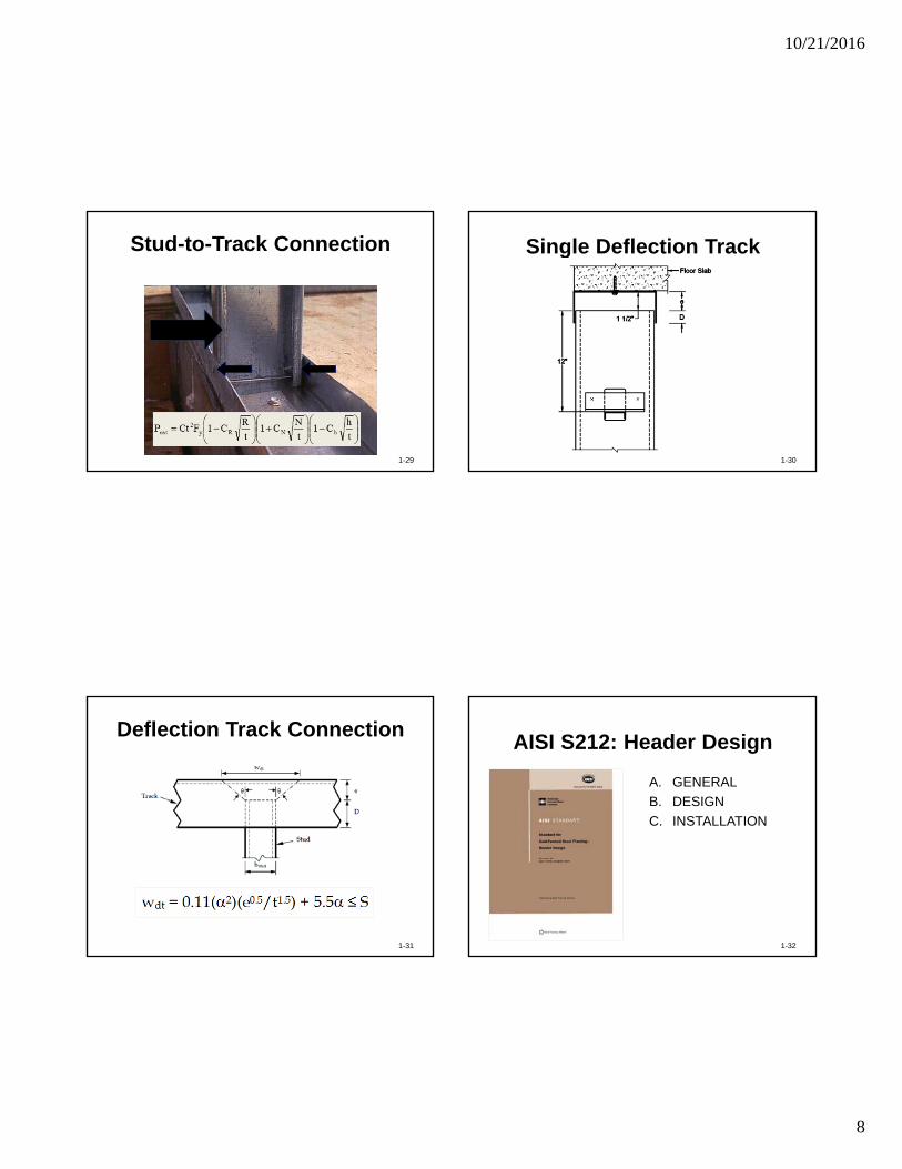
Stud-to-Track Connection
1-29
Single Deflection Track
1-30
Deflection Track Connection
1-31
wdt
bstud
Stud
Track
D
e
AISI S212: Header Design
A. GENERAL
B. DESIGN
C. INSTALLATION
1-32
10/21/2016
9
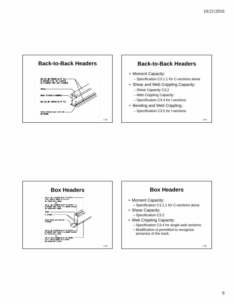
Back-to-Back Headers
1-33
Back-to-Back Headers
• Moment Capacity:– Specification C3.1.1 for C-sections alone
• Shear and Web Crippling Capacity:– Shear Capacity C3.2
– Web Crippling Capacity:
– Specification C3.4 for I-sections
• Bending and Web Crippling:– Specification C3.5 for I-sections
1-34
Box Headers
1-35
Box Headers
• Moment Capacity:– Specification C3.1.1 for C-sections alone
• Shear Capacity:– Specification C3.2
• Web Crippling Capacity:– Specification C3.4 for single-web sections– Modification is permitted to recognize
presence of the track
1-36
10/21/2016
10
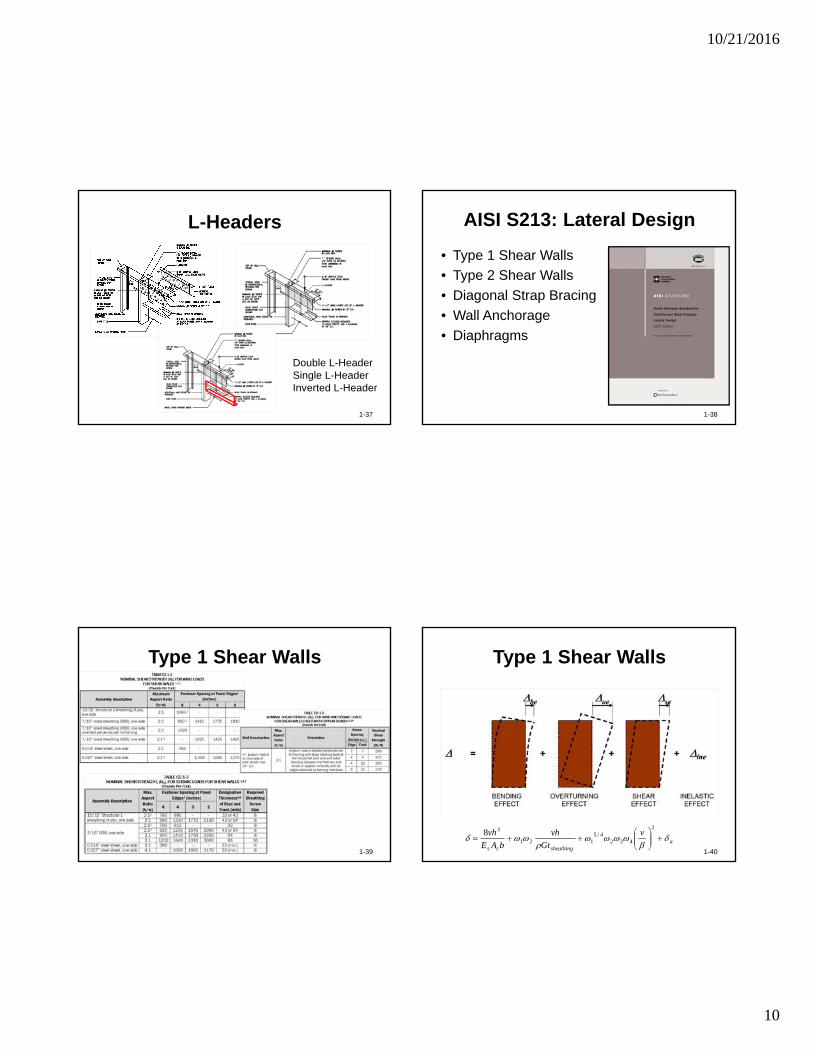
L-Headers
1-37
Double L-HeaderSingle L-HeaderInverted L-Header
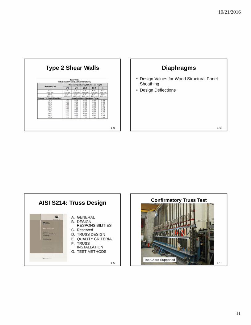
AISI S213: Lateral Design
• Type 1 Shear Walls
• Type 2 Shear Walls
• Diagonal Strap Bracing
• Wall Anchorage
• Diaphragms
1-38
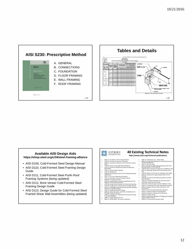
Type 1 Shear Walls
1-39
Type 1 Shear Walls
1-40
asheathingcs
v
Gt
vh
bAE
vh
2
4324/5
121
38
10/21/2016
11
Type 2 Shear Walls
1-41
Diaphragms
• Design Values for Wood Structural Panel Sheathing
• Design Deflections
1-42
AISI S214: Truss Design
A. GENERALB. DESIGN
RESPONSIBILITIESC. ReservedD. TRUSS DESIGNE. QUALITY CRITERIAF. TRUSS
INSTALLATION G. TEST METHODS
1-43
Confirmatory Truss Test
1-44Top Chord Supported
10/21/2016
12
AISI S230: Prescriptive Method
A. GENERAL
B. CONNECTIONS
C. FOUNDATION
D. FLOOR FRAMING
E. WALL FRAMING
F. ROOF FRAMING
1-45
Tables and Details
1-46
Available AISI Design Aidshttps://shop.steel.org/c/34/steel-framing-alliance
• AISI D100, Cold-Formed Steel Design Manual
• AISI D110, Cold-Formed Steel Framing Design Guide
• AISI D111, Cold-Formed Steel Purlin Roof Framing Systems (being updated)
• AISI D112, Brick Veneer Cold-Formed Steel Framing Design Guide
• AISI D113, Design Guide for Cold-Formed Steel Framed Shear Wall Assemblies (being updated)
40 Existing Technical Noteshttp://www.cfsei.org/technical‐publications
• D001‐13, Durability of CFS Framing Members• D100‐13, Corrosion Protection of Fasteners• D200‐12, Corrosion Protection for CFS Framing in Coastal
Areas • F100‐09, Design of Clip Angle Bearing Stiffeners• F101‐12, Screws for Attachment of Steel‐To‐Wood and
Wood‐Steel• F102‐11, Screw Fastener Selection• F140‐10, Welding CFS• F300‐09, Pneumatically Driven Pins for Wood‐Based Panel
Attachment• F501‐11, CFS Truss to Bearing Connections• F701‐12, Evaluation of Screw Strength Capacity• G000‐08, CFS Design Software• G100‐07, Using Chapter F of the NA Specification for the
Design of CFS Structural Members• G101‐08, Design Aids & Examples for Distortional Buckling• G102‐09, Designing CFS using the Direct Strength Method• G103‐11a, Tabulated Local and Distortional Elastic Buckling
Solutions for Standard Shapes• G104‐14, Welded Boxed‐Beam Design• G200‐15, Chase the Loads ‐ Load Path Considerations for
CFS Light‐Frame Construction• G500‐11, Guidelines for Inspecting CFS Structural Framing
in Low Rise Buildings• G800‐12, ASTM Standards for CFS• G801‐13, ASTM A1003 ‐ No Cause for Rejection
• G802‐13, AISI Section A2.2 ‐ Other Steels• G900‐15, Design Methodology for Hole Reinforcement of
CFS Bending Members• J100‐11, CFS Floor Joists• L001‐10, Design of Diagonal Strap Bracing Lateral Force
Resisting Systems for the 2006 IBC• L200‐09, Roof Framing Anchorage Forces: MWFRS or C&C• L202‐12, Diaphragm Design with Pneumatically Driven
Pins• L300‐09, Design of End Posts for Diaphragm Shear Walls• S100‐16, Antiterrorism Design Requirements for CFS
Framing• T001‐09, Fire and Acoustic‐Rated Assemblies for Multi‐
Unit Structures• T100‐12, Fire‐Rated Assemblies for CFS Construction • W100‐08a, Single Slip Track Design• W101‐09, Common Design Issues for Deflection Track• W102‐12, Introduction to Curtain Wall Design Using CFS• W103‐11, Design of By‐Pass Slip Connectors in CFS
Construction• W104‐10, Top Track Load Distribution Members• W105‐13, Design of Nonstructural Members• W106‐16, Design for Splicing of CFS Wall Studs• W200‐09, Header Design• W400‐16, Mechanical Bridging and Bridging Anchorage of
Axially Loaded CFS Studs• W500‐12, Construction Bracing for Walls
10/21/2016
13
Wei-Wen Yu
Center for Cold-Formed Steel Structure
[email protected], 573-341-4481
QUESTIONS?
1-50