New Design Method for Cold-Formed Purlins
19
Missouri University of Science and Technology Scholars' Mine International Specialty Conference on Cold- Formed Steel Structures (1988) - 9th International Specialty Conference on Cold-Formed Steel Structures Nov 8th New Design Method for Cold-formed Purlins Frans Soetens A. W. Toma Follow this and additional works at: hp://scholarsmine.mst.edu/isccss Part of the Structural Engineering Commons is Article - Conference proceedings is brought to you for free and open access by the Wei-Wen Yu Center for Cold-Formed Steel Structures at Scholars' Mine. It has been accepted for inclusion in International Specialty Conference on Cold-Formed Steel Structures by an authorized administrator of Scholars' Mine. For more information, please contact [email protected]. Recommended Citation Frans Soetens and A. W. Toma, "New Design Method for Cold-formed Purlins" (November 8, 1988). International Specialty Conference on Cold-Formed Steel Structures. Paper 4. hp://scholarsmine.mst.edu/isccss/9iccfss-session1/9iccfss-session2/4
-
Upload
bui-hong-lenh -
Category
Documents
-
view
83 -
download
1
description
New Design Method for Cold-Formed Purlins
Transcript of New Design Method for Cold-Formed Purlins
Missouri University of Science and TechnologyScholars' MineInternational Specialty Conference on Cold-Formed Steel Structures
(1988) - 9th International Specialty Conference onCold-Formed Steel Structures
Nov 8th
New Design Method for Cold-formed PurlinsFrans Soetens
A. W. Toma
Follow this and additional works at: http://scholarsmine.mst.edu/isccss
Part of the Structural Engineering Commons
This Article - Conference proceedings is brought to you for free and open access by the Wei-Wen Yu Center for Cold-Formed Steel Structures atScholars' Mine. It has been accepted for inclusion in International Specialty Conference on Cold-Formed Steel Structures by an authorizedadministrator of Scholars' Mine. For more information, please contact [email protected].
Recommended CitationFrans Soetens and A. W. Toma, "New Design Method for Cold-formed Purlins" (November 8, 1988). International Specialty Conferenceon Cold-Formed Steel Structures. Paper 4.http://scholarsmine.mst.edu/isccss/9iccfss-session1/9iccfss-session2/4
Ninth International Specialty Conference on Cold-Formed Steel Structures St_ Louis, Missouri, U.S.A., November 8-9,1988
NEW DESIGN METHOD FOR COLD-FORMED PURLINS
by: ir. F. Soetens and ir. A.W. TomA Steel Structure Department of the Institute TNO for Building Materials and Structures, Delft, The Netherlands.
1. INTRODUCTION
In Europe, a growing tendency exists for the application of cold-formed sections (e.g. Z-, ~- or C-sections) as purlins in combination with trapezoidal sheeting. For such systems, the following items are characteristic:
- the load can be due to gravity (dead and snow load) or uplift (wind-suction) ;
- the non-symmetrical cross section of these purlins implies a sensitivity to torsional behaviour; the sheeting connected to the purl in gives a restraint against this torsion.
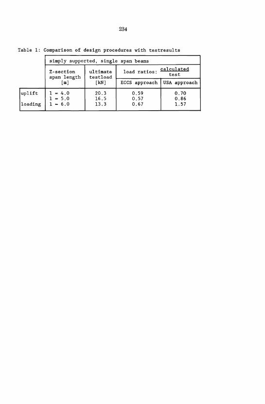
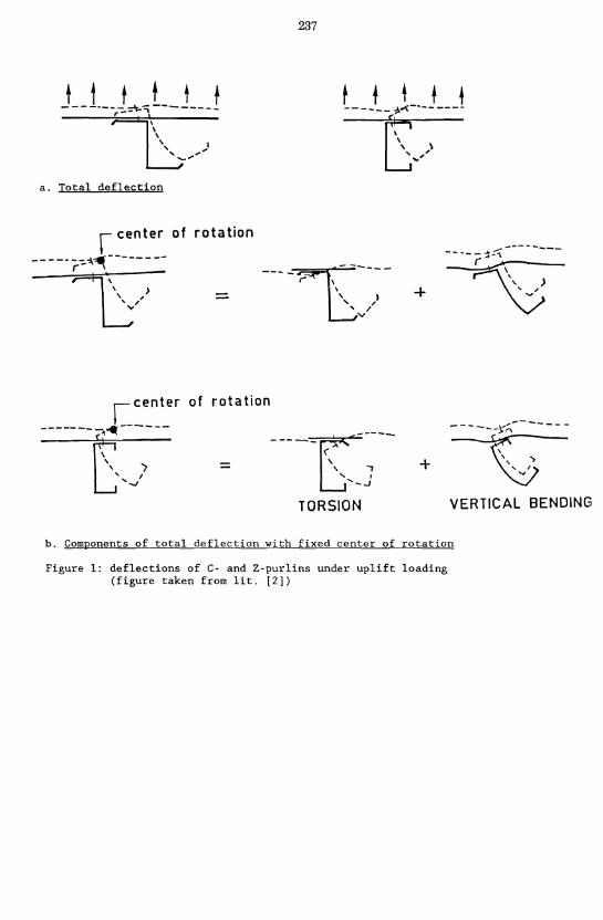
Figure 1 shows the deflections of C- and Z-purlins under uplift loading. It may be clear that a design procedure should be based on the composite action between sheeting and purl in. References [lJ (which is based on references [3J and [4J) and [2J give such design procedures. Table 1 gives a comparison of both procedures with results from tests on cold-formed Z-sections of SAB Profiel BV (Dutch manufacturer) . This paper describes a more optimal procedure, using a calculation model based on a research programme executed at TNO-IBBC. A litarature study has been carried out in the beginning of the programme (ref. [5J). A number of references have been listed, of which [2], [3J and [4J seem to be the most important. Based on this study, a design hypothesis has been derived. To check the hypothesis, a testing programme has been executed (ref. [6J). The comparison of test results and calculations has been given in references [7J and [8J. Finally, in reference [9], a survey of the whole programme has been given, including recommendations for a design procedure. This paper will focus on the hypothesis and the comparison with test results. The hypothesis has been based largely on the work by Pek6z and Soroushian (lit. [2J). The main additions are:
for uplift loading, the load transfer between sheeting and purlin via the fasteners will be taken into account; second order effects caused by compressive stresses in the free flange have been taken into account in the buckling curves and not introduced through initial imperfection.
2. DESIGN HYPOTHESIS FOR DIAPHRAGM BRACED BEAMS
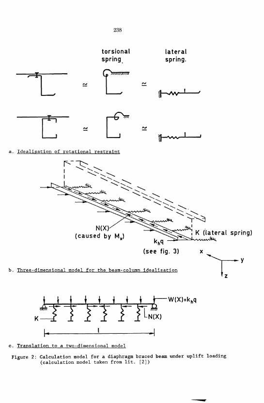
Figure 2 shows schematically the hypothesis for the calculations on a diaphragm braced beam under uplift loading. For gravity loading, a comparable scheme can be made. According to the scheme, the stresses in the section are a combination of:
229
230
- stresses from in-plane bending of the entire section due to the load q. These generate an axial force N (x) in the free flange of the section (see fig. 2b and 2c). This axial force varies along the length of the member due to the in-plane bending moment M (x); with uplift, N (x) is a compressive force and with gravity, N (x) is a tensile force.
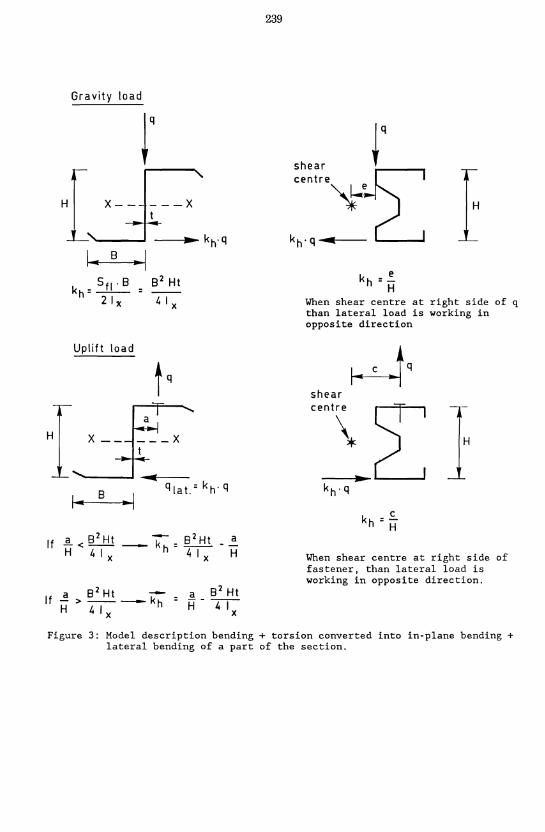
- stresses from lateral bending of a part of the section due to the lateral load ~q. The value of ~ is shown in figure 3.
For determining the in-plane bending stresses the effective widths of compressed parts of the section are applied to account for local buckling effects. The stresses caused by the lateral load of the free flange will be determined without reducing the width of the free flange.
With diaphragm braced beams, the rotation of the beam is restrained by: - the section properties of the diaphragm, - the section properties of the beam, - the connection between diaphragm and beam. Usually this rotational restraint is converted into a lateral restraint as indicated in fig. 2a (taken from [2]), being a linear extensional spring with stiffness K located at the level of the free flange. This means that the part of the section due to lateral bending (and with uplift loading also a compressive load, as explained later) can be calculated as a beam on an. elastic foundation (see figure 2b and 2c). Reference [9] gives the procedure to determine K. With the energy method, the combination of stresses will be applied. In the energy equation, the following are taken into account: - energy due to lateral load - energy due to axial force - flexural strain energy of the free flange - elastic foundation strain energy (caused by the rotational restraint of
the sheeting) This leads to equations for actual stresses depending on the edge conditions as given in appendix II. This means that imperfections (e.g. initial deflections, residual stresses) have been neglected.
As criteria for the ultimate limit state, the actual stresses will be smaller than the yield stress or the ultimate stress for flexural/torsional buckling of the free flange when it is under compression. The ultimate stress for flexural/torsional buckling will be determined in a model based on a beam-column behaviour of a part of the section. The load-bearing capacity of the beam-column is checked as follows:
w a c
Where: w a c
buckling coefficient compressive stress due section
to in-plane bending of entire (effective)
lateral bending moment acting in the free flange plus height of the web (see appendix II)
1 6th of the
section modulus based on moment of inertia (I fy ) of a part of the section yield stress
231
The buckling coefficient w depends on the slenderness X, for which following have to be taken into account: - a variable axial force along the length of the bar, - an elastic foundation, and - appropriate end conditions. In appendix III the resulting stability check equations are formulated.
It may be noted that in the model to check the beam-column capacity the influence of the energy due to the axial force has been taken into account twice (in wand in M ). For reasons of uniformity with the column philosophy, an "w" fb±~ulation is choosen (e.g. same initial deflections and residual stresses) because in M( ) the imperfections have not been taken into account. y Furthermore, the value of wa in the equation is always higher than the value of the second term (laferal bending contribution).
a. For gravity loaded systems the ultimate limit state has been defined by appearance of a failure mechanism. Ultimate moment capacity in the midspan should be determined theoretically (in principle according to 2.1, although in practice this means yield stress mUltiplied by the section modulus of the effective cross section) or by testing (single span tests with a span comparable with the length of the positive moment area). For the behaviour over the support, detailed support tests are necessary. These tests should provide information about the rotation over the support after reaching the maximum moment. The governing mechanism of the system will be reached at ultimate moment capacity in the mid-span and compatibility of moment and rotation over the support. As serviceability limit state has been defined reaching maximum moment capacity over a support with a load factor of 1.1. and deflection at mid-span.
b. For uplift loaded systems the ultimate limit state has been defined by the smallest of following loads: - The load at which the maximum moment at the support is reached. Only
local buckling should be taken into account according to reference [1]. The interaction of the support reaction with the moment may be neglected because it is introduced as a "tension" force.
- The load at which the maximum moment in the span is reached according to 2.2.a.
For the force distribution an elastic behaviour may be assumed. As serviceability limit state a deflection requirement at mid-span governs.
c. For overlap or sleeve systems the design procedure is as follows: Detailed support tests should be executed. Only the increasing part of the load-deflection curve is of interest.
- From the tests, the following can be derived: i. the stiffness of the overlapping or sleeved part ii. failure combination of bending moment + support reaction (in
overlapped or sleeved part) or bending moment + shear force (besides overlapped or sleeved part).
232
- With item "i" the force distribution in the system can be determined (also where local buckling of the cross section in the span is taken into account).
- The force distribution shall be checked for: * failure combinations of bending moment + support reaction or bending
moment + shear force (near support) * maximum moment capacity in span according to 2.2.a., neglecting the
influence of overlap or sleeve * the allowable deflections
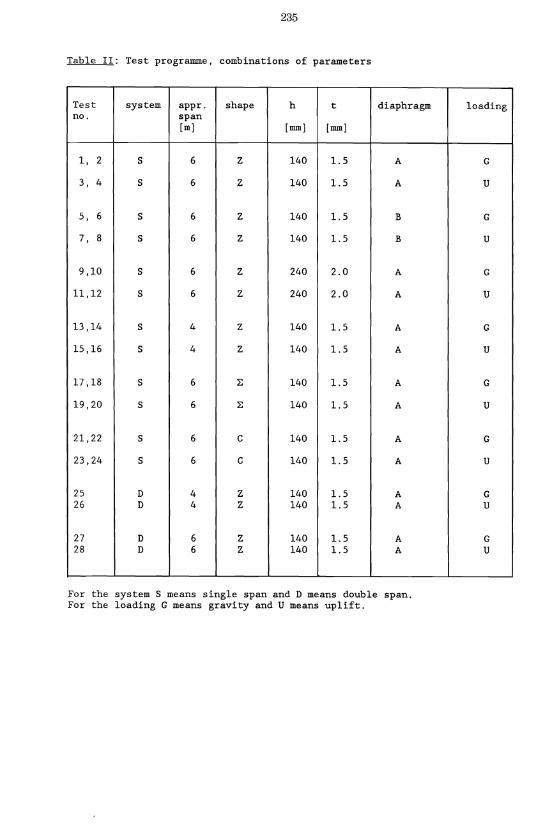
TEST PROGRAMME
In reference [6], the testing programme on C-, Z-, and L-sections has been described. The report also comprises the results of the tests and a comparison of these results. The specimens have been built up as two parallel purl ins with sheeting over it. The specimens are placed in a box and loaded by suction due to a vacuum. The choice of test specimens has been determined in such a way that almost every test will be executed in two-fold. Between the different specimens only one parameter has been varied. The combinations of parameters which have been used are: - single span and double span - spans of about 4 m and 6 m - shape of the section of the purlins Z, C and L - section height of the purlins h - 140 mm and h - 240 mm
section thickness of the purl ins t - 1.5 mm at the height h - 140 mm and t - 2.0 mm at the height h - 240 mm
- two types of torsional restraint delivered to the purlins by sheeting (type A and B) type of loading; gravity and uplift (The test specimens were to be acted upon only by vertical uniformly distributed loading)
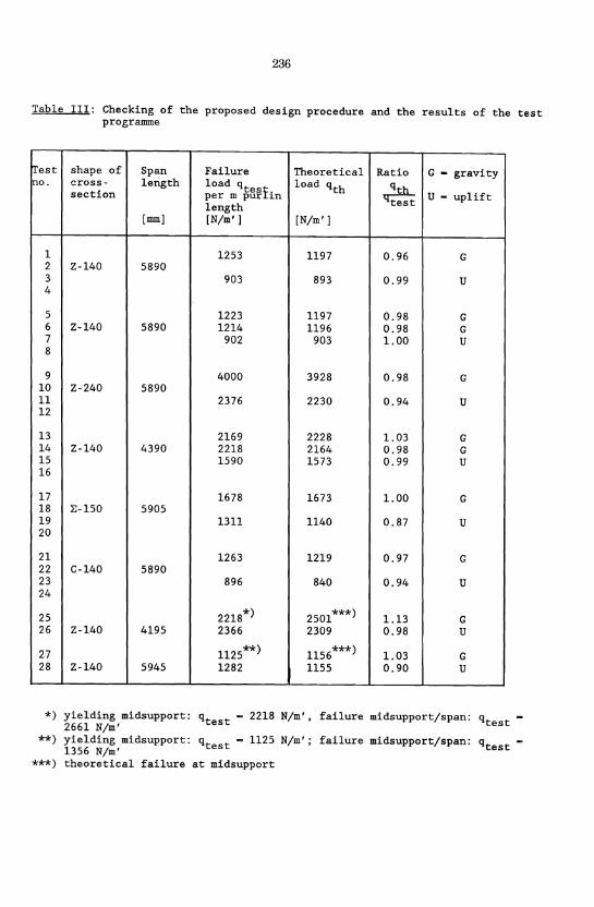
Table II gives a survey of the total of 28 test specimens. The failure loads in the test are summarized in table III.
4. COMPARISION OF CALCULATION PROCEDURE AND TEST RESULTS
The behaviour of the test specimens has been predicted by the calculation procedure given in paragraph 2. The comparison is given in table III as ratio qth/qtest' With respect to these results it can be obse:ved that: - For s~ngle span beams all test results are very well approx~mated for
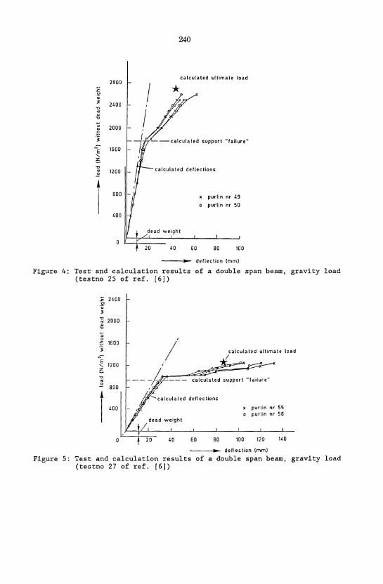
gravity loading (ratios: 0.96 - 1.03). - For double span beams the failure loads for gravity loading are higher
than the theoretical results (without redistribution of moment). If yielding at mid-support, observed during the test, should be taken as failure, the moment capacity of the mid-support is overestimated by 13% in test 25 and 3% in test 27. This overestimation is due to the support reaction. However, in the tests redistribution of forces after yielding at mid-support occurs, which allows yielding/failure in the span, while theoretically failure is defined as yielding at mid-support. Taking into account the moment redistribution the results will be as shown in the figures 4 and 5, which shows a very good approximation.
- For single span beams and uplift loading, all test results are very well approximated (ratios: 0.87 - 1.00).
233
- For double span beams and uplift loading, theoretical failure occurs with yielding at mid-support, while during the tests failure occured simultaneously at mid-support and in the span. Therefore, in accordance with the above described situation with gravity loading, there could have been a redistribution of forces at mid-support, which explains the higher test results particulary with test 28. To allow for a small amount of conservatism (qth is smaller than qf'l for the mid-support) and also because the ~a~e conditions at mid-~frp~5ft for stability check in the span will change rigorously when mid-support fails the procedure as shown in 2.2.b. has been proposed.
5. SUMMARY
The research carried out in the project described in this paper concentrates on the behaviour and load carrying capacity of diaphragm braced beams using cold-formed sections.
A hypothesis for a calculation model, partly based on reference [2] has been developed. To check the resulting model, a number of tests has been executed: - 24 tests on simply supported beams, - 4 tests on double span beams and - 4 detailed support tests.
On basis of these tests the calculation model has been improved. Finally this has led to a recommendation for a design procedure for diaphragm braced beams which is formulated in detail in reference [9]. Furthermore, it is recommended that some detailed support tests be used as one of the input parameters for designing purlin-systems. Only then can the ultimate load bearing capacity of the system be predicted. It is also sensible to do tests for the torsional restraint of the purl in delivered by the sheeting. The values for the torsional restraint given in the reference [9] are on the conservative side.
ACKNOWLEDGEMENTS
The research programme executed at TNO-IBBC has been financial supported by: - The European Community for Steel and Coal (contract no. 72l0jSAj608); - Stichting Koudprofileurs (Dutch foundation of cold rolling
manufacturers); - Staalbouwkundig Genootschap (Dutch foundation for coordination of steel
research) .
234
Table 1: Comparison of design procedures with testresults
simply supported, single span beams
Z-section ultimate load ratios: calculated
span length testload test
[m] [leN] ECCS approach USA approach
uplift 1 = 4.0 20.3 0.59 0.70 1 - 5.0 16.5 0.57 0.86
loading 1 = 6.0 13.3 0.67 1. 57
235
Table II: Test programme, combinations of parameters
I
Test system appro shape h t diaphragm no. span
[m] [mm] [mm]
1, 2 S 6 Z 140 1.5 A
3, 4 S 6 Z 140 1.5 A
5, 6 S 6 Z 140 1.5 B
7, 8 S 6 Z 140 1.5 B
9,10 S 6 Z 240 2.0 A
11,12 S 6 Z 240 2.0 A
13,14 S 4 Z 140 1.5 A
15,16 S 4 Z 140 1.5 A
17,18 S 6 2.: 140 1.5 A
19,20 S 6 2.: 140 1.5 A
21,22 S 6 C 140 1.5 A
23,24 S 6 C 140 1.5 A
25 D 4 Z 140 1.5 A 26 D 4 Z 140 1.5 A
27 D 6 Z 140 1.5 A 28 D 6 Z 140 1.5 A
For the system S means single span and D means double span. For the loading G means gravity and U means uplift.
loading
G
U
G
U
G
U
G
U
G
U
G
U
G U
G U
236
Table III: Checking of the proposed design procedure and the results of the test programme
!rest shape of Span Failure Theoretical Ratio G - gravity Ino. cross- length load qtes£. load qth qth section per m pur ~n qtest U - uplift
length [mml [N/m'l [N/m'l
1 1253 1197 0.96 G 2 Z-140 5890 3 903 893 0.99 U 4
5 1223 1197 0.98 G 6 Z-140 5890 1214 1196 0.98 G 7 902 903 1.00 U 8
9 4000 3928 0.98 G 10 Z-240 5890 11 2376 2230 0.94 U 12
13 2169 2228 1.03 G 14 Z-140 4390 2218 2164 0.98 G 15 1590 1573 0.99 U 16
17 1678 1673 1.00 G 18 ~-150 5905 19 1311 1140 0.87 U 20
21 1263 1219 0.97 G 22 C-140 5890 23 896 840 0.94 U 24
25 2218*) 2501***) 1.13 G 26 Z-140 4195 2366 2309 0.98 U
27 1125**) 1156***) 1.03 G 28 Z-140 5945 1282 1155 0.90 U
*) yielding midsupport: qtest - 2218 2661 N/m'
N/m' , failure midsupport/span: qtest -
**) yielding midsupport: qtest = 1125 1356 N/m'
N/m' ; failure midsupport/span: qtest -
***) theoretical failure at midsupport
a. Total deflection
r center of
-----~-:--, , ' .. ./
237
rotation
--- - r- \ L;------
rotation
=
\ , I " , , /
'"'
----t=\ -----, .
.... I .... --1
TORSION
+
+
-----:i.::\--------
~ V
----{;----, / ...,
VERTICAL BENDING
b. Components of total deflection with fixed center of rotation
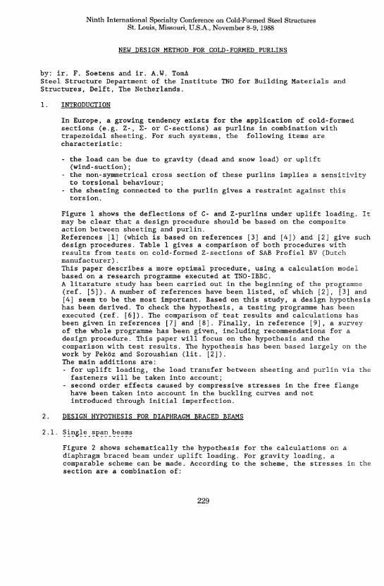
Figure 1: deflections of C- and Z-purlins under uplift loading (figure taken from lit. [2])
c
238
torsional spring.
a. Idealisation of rotational restraint
N(X) (caused by Mx)
lateral spring.
(see fig. 3)
b. Three-dimensional model for the beam-column idealisation
-I c. Translation to a two-dimensional model
x
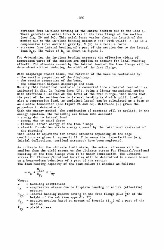
Figure 2: Calculation model for a diaphragm braced beam under uplift loading (calculation model taken from lit. [2])
-
Gravity load
r I .. B .. /
Uplift load
... I ... 8 ~I
If 1!. < 8 2 Ht H 4 I x
a 8 2 Ht H - -4-1-
x
239
kh = .:.. H
When shear centre at right side of q than lateral load is working in opposite direction
When shear centre at right side of fastener, than lateral load is working in opposite direction.
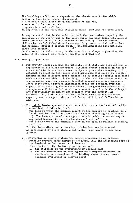
Figure 3: Model description bending + torsion converted into in-plane bending + lateral bending of a part of the section.
2800
~ ";
2400 "" ~ ~ 2000 :S ·i Ne 1600 .... ~
"" .. ~
1200 -
1 800
400
240
calculated ultimate load
*
--calculated support -failure-
calculated deflections
dead weight
60
x purlin nr '9 o purlin nr 50
80 100
---la-a.- deftection (mm)
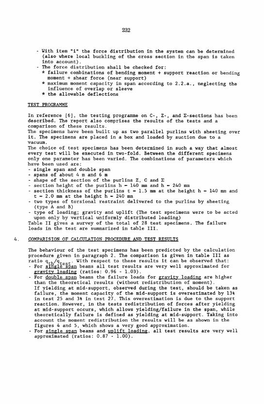
Figure 4: Test and calculation results of a double span beam, gravity load (testno 25 of ref. [6])
.c 2400 '" "; ~ 2000
" 0 -" 1600 ·i N~
1200 '-~
"" .. ~ 800
1 400
calculated ultimate load I
-- - calculated support HfaHure"
calcula ted de flections
60 80 100
purlin nr 55 purlin nr 56
120
-----.., .. _ deflection (mm)
Figure 5: Test and calculation results of a double span beam, gravity load (testno 27 of ref. [6])
241
Appendix I: References
[1] European Recommendations for the Design of light gauge steel members, ECCS-TWG 7/1 - First edition 1987.
[2] Pek~z, T., Soroushian, P. "Behaviour of C- and Z-purlins under wind uplift", Cornell University Ithaca, N.Y., February, 1981.
[3] Sokol, L. "Calcul des pannes en section Z", Construction M~tallique, no. 1 - 1979.
[4] Sokol, L. "Calcul de la longueur de flambement de la semelle comprim~e des pannes en Z", Construction M~tallique no. 2 - 1980.
[5] F. Soetens and A.W. Toma Research for the mechanical behaviour of cold-formed sections and drafting of design rules. Literature study. TNO-IBBC report BI-84-55, September 1984.
[6] A.A. Kip and A.W. Toma Research for the mechanical behaviour of cold-formed sections and drafting of design rules. Report of testing of diaphragm braced beams. TNO-IBBC report BI-86-54, August 1986.
[7] F. Soetens and A.W. Toma Research for the mechanical behaviour of cold-formed sections and drafting of design rules. Design procedure of diaphragm braced beams. TNO-IBBC report BI-87-l2, February 1987.
[8] A.W. Toma Research for the mechanical behaviour of cold-formed sections and drafting of design rules. Detail support tests for continuous systems and the derivation of a design procedure. TNO-IBBC report BI-87-8l, August 1987.
[9] F. Soetens and A.W. Toma Research for the mechanical behaviour of cold-formed sections and drafting of design rules. Final report. TNO-IBBC report BI-87-l00, September 1987
242
Appendix II: Determination of actual stresses (based on lit. [2] and figure 3)
The actual stresses in a cross section in the field follow from:
{J a
a a
!:L.UU W (for braced flange) ef
!:L.UU Wef
+ ~ (for free flange) Wfy
Herein: M (x)
M (y)
bending moment at a place x in the field due to the component of the design load acting in web direction section modulus for the effective cross section according to ref. [1] section modulus of the free flange plus 1/6 of the height of the web against lateral bending (for gross section of free flange)
f / q lq
lJ..c------,..] E
c o ax
I I o ax
M (x) = w;;-
2 El fy 1r
i 2 Al (lateral bending moment)
r- .. ·· ..
+ 1/6 h+L e ~
Yl
Young's modulus moment of inertia (of gross section) of the free flange plus 1/6 of the height of the web against lateral bending span of the purlin constant depending on edge conditions of the purlin in lateral direction
243
At midspan and compression stress in the free flange, for Al may be taken:
- Simply supported beam:
4~ q;.4
- Beams,
5 4 Sf 4 E1 fy 1f + K;' 1f - 1. 8 -I - q ;.
both ends fixed: ef
4~ q;.4 Al - --------'''-----------
4 4 Sf 4 16 E1 fy 1f + 3 K ;. 3.54 r-- q ;.
ef
- Beams, one end fixed and one end simply supported:
Herein:
5 K n 4 E1 fy 1f + .. 1f -
according to figure 3
Sf 4 1. 22 r-- q ;.
ef
the component of the design load acting in web direction span of the beam see before lateral spring stiffness according to ref. [9]; depending on place of centre of rotation of the beam static moment of the free flange plus 1/6 of the height of the web about the neutral axis (the effective cross section is governing) the moment of inertia of the effective cross section of the whole beam.
When the free flange is in tension, then the "-" sign in the denominater should be a 11+" sign.
244
Appendix III: Stability check of free flange in compression
The stability of the free flange in compression shall be checked as follows:
M...J..li + M....lll :5 f W Wef Wfy ty
Herein: M (x), M(y), Wef' Wfy and f ty see appendix II
W buckling co~ffici~nt
W - -T"-7Q~==;;:==-, F -V F2 !L I
X2
A Ag .eff ~fy
£ cr
Aeff Q - p:-
g
F 1/2 (Q + 1 + n eX - o,2)} X2
~ = 0.34 (4 - 3Q) ~ 0.76
X _ ~cr • 1\ ~ ~fy ".V E
area of gross cross section area of effective cross section belonging to M(x) radius of gyration of gross cross section of free flange plus 1/6 of web height against lateral bending buckling length depending on edge conditions in lateral deflections - simple supported beam
£V~ n 2 ".2 - 21
£cr - ; n4 + R
n - V 0.3 + V 0.09 + R,I a
n - next higher integer value of na - beams, both ends fixed
n a
n
l!. n2 ".2 + Z g 9 3 ". 16 n 4 + R
3
0.66~
next higher integer value of na
R
K
245
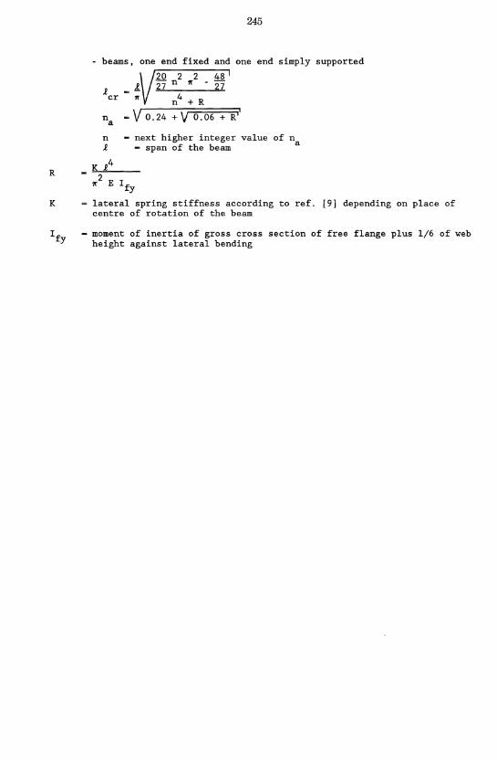
- beams, one end fixed and one end simply supported
1. cr
n a
n 1.
20 2 2 48 27 n 1£ 27
1£ n 4 + R
~ V 0.24 + V 0.06 + R ii
next higher integer value of na ~ span of the beam
2 1£ E I fy
lateral spring stiffness according to ref. [9] depending on place of centre of rotation of the beam
- moment of inertia of gross cross section of free flange plus 1/6 of web height against lateral bending