Composite Beams of Cold Formed Steel Section and Concrete … · Composite Beams of Cold Formed...
13
© 2016 IJEDR | Volume 4, Issue 4 | ISSN: 2321-9939 IJEDR1604030 International Journal of Engineering Development and Research ( www.ijedr.org ) 165 Composite Beams of Cold Formed Steel Section and Concrete Slab 1 M. A. YOUNS, 2 S.A. HASSANEEN, 3 M.R. BADR and 4 E.S. SALEM 1 Assistant lecturer, Civil Eng. Dept., Azhar University, Qena, Egypt, 2 Prof. Civil Eng. Dept., Azhar University, Cairo, Egypt, 3 Prof. Civil Eng. Dept., the researches center for housing and building, Giza, Egypt, 4 Associate prof. Civil Eng. Dept., Azhar University, Cairo, Egypt. Abstract-This work presents the experimental tests which were carried out to examine the structural behavior of composite beam of cold formed steel with concrete slab. Seven innovative composite beams cold formed steel lipped channel sections (CFS) with concrete slab, taken into account the effect of bent up half flange for the channel as a new shear dowel, were studied the test parameters include shape of shear dowel, thickness of CFS and concrete slab thickness. The results showed that by increasing the thickness of CFS will lead to an increase in the ultimate load of composite beams. Furthermore, by increasing thickness of concrete slab will provide an increase in the ultimate load. Keywords: Composite; Cold-formed;; Large-scale test; Bent-up of the half flange channel; Flexural capacity 1. INTRODUCTION In recent years, composite construction becomes more popular and broadly accounts for the dominance of steel frames in the construction sector in many developing countries. The main structural benefits of using composite beams can be listed as follows: 1. Savings in steel weight are typically 30 to 50% over non-composite beams relyed on hot-rolled sections due to greater stiffness. 2. The main economy sought in buildings is speed of construction. Cold-formed steel (CFS) sections, usually between 1.2 mm to 3.2 mm thickness, have been recognized as an important contributor to sustainable structures in the developed nations. Recent studies on composite beams with CFS had been reported by other researchers who agree about their application of CFS beams and composites with concrete [1]. However, there remains a lack of data on the behaviour and performance of CFS in composite construction. One limiting advantage of CFS is the thinness of its section that makes it susceptible to torsional, distortional, lateral torsional, lateral distortional and local buckling. Hence, a sensible solution is resorting to a composite construction of structural CFS section and reinforced concrete deck slab. This reduce the distance from the neutral-axis to the top of the deck and reduces the compressive bending stress in the CFS sections. 2. PERVIOUS WORK The population growth in the world has an increase in the demand of residential construction and houses. Dannemann, R. W., (1982) [2] introduced low cost house structure system using cold formed steel sections, which is one of the most efficient and economic structural members. In the past 25 years, wide growth of using cold formed steel sections in residential construction has been reported. Pekoz (1999) [3] states that, in the United States, there were about 500 houses built in light gauge steel in 1992. This number rose to 15,000 in 1993, 75,000 in 1994. In Australia, about 40000 new homes using load bearing cold formed steel framing are constructed per year (Hancock G. J. And Murray, T. M., 1996 [4]). In Malaysia, recent development includes the increased application of light steel trusses consisting of cost-effective profiled cold-formed channels and steel portal frame systems as alternatives to the heavier traditional hot-rolled sections (CIDB, 2003) [5]. With fast and accurate manufacturing, ease handling and transportation, efficiency in cost and material, high strength-to-weight ratio, speed in erection, fully recyclable, durability, cold-formed steel sections could be an alternative economic structural components and frame systems for residential and commercial construction (Dannemann, R. W., 1982 [2]; Yu, W., 2000 [6]; Allen, D., 2006 [7]). The use of cold formed steel sections with concrete to shape composite beams can be a new alternative solution to replace hot rolled steel and reinforced concrete beams in small and medium size buildings (Hossain, 2005) [8]. Also, a significant reduction in the cost of light-gauge construction could be expected since the composite action will minimize the size of steel sections and thickness of concrete slabs needed. In the past 25 years, few researchers (Hanaor, 2000 [9]; Lawson et al., 2001 [10]; Hambro [11]; Lakkavali and Yu, 2006 [12]; Irwan, 2009 [1]; Irwan, 2011 [13] Wehbe, 2011 [14]) had investigated the feasibility of designing cold formed steel section and concrete slab as composite beams. It was found that cold formed section and concrete slabs could be act compositely; thickness of cold formed steel section, the concrete strength and the degree of shear connection depends on the type, shape, spacing and configuration of shear connector. In this research, a new technique of shear dowels for composite beams which consists of lipped channels cold formed steel beam and concrete slab. The Innovative shear
Transcript of Composite Beams of Cold Formed Steel Section and Concrete … · Composite Beams of Cold Formed...
© 2016 IJEDR | Volume 4, Issue 4 | ISSN: 2321-9939
IJEDR1604030 International Journal of Engineering Development and Research (www.ijedr.org) 165
Composite Beams of Cold Formed Steel Section
and Concrete Slab
1M. A. YOUNS,
2S.A. HASSANEEN,
3M.R. BADR and
4E.S. SALEM
1Assistant lecturer, Civil Eng. Dept., Azhar University, Qena, Egypt, 2Prof. Civil Eng. Dept., Azhar University, Cairo, Egypt, 3Prof. Civil Eng. Dept., the researches center for housing and building, Giza, Egypt, 4Associate prof. Civil Eng. Dept., Azhar
University, Cairo, Egypt.
Abstract-This work presents the experimental tests which were carried out to examine the structural behavior of
composite beam of cold formed steel with concrete slab. Seven innovative composite beams cold formed steel lipped
channel sections (CFS) with concrete slab, taken into account the effect of bent up half flange for the channel as a new
shear dowel, were studied the test parameters include shape of shear dowel, thickness of CFS and concrete slab thickness.
The results showed that by increasing the thickness of CFS will lead to an increase in the ultimate load of composite
beams. Furthermore, by increasing thickness of concrete slab will provide an increase in the ultimate load.
Keywords: Composite; Cold-formed;; Large-scale test; Bent-up of the half flange channel; Flexural capacity
1. INTRODUCTION
In recent years, composite construction becomes more popular and broadly accounts for the dominance of steel frames
in the construction sector in many developing countries. The main structural benefits of using composite beams can be listed as
follows:
1. Savings in steel weight are typically 30 to 50% over non-composite beams relyed on hot-rolled sections due to greater
stiffness.
2. The main economy sought in buildings is speed of construction.
Cold-formed steel (CFS) sections, usually between 1.2 mm to 3.2 mm thickness, have been recognized as an important
contributor to sustainable structures in the developed nations. Recent studies on composite beams with CFS had been reported by
other researchers who agree about their application of CFS beams and composites with concrete [1]. However, there remains a
lack of data on the behaviour and performance of CFS in composite construction. One limiting advantage of CFS is the thinness
of its section that makes it susceptible to torsional, distortional, lateral torsional, lateral distortional and local buckling. Hence, a
sensible solution is resorting to a composite construction of structural CFS section and reinforced concrete deck slab. This
reduce the distance from the neutral-axis to the top of the deck and reduces the compressive bending stress in the CFS sections.
2. PERVIOUS WORK
The population growth in the world has an increase in the demand of residential construction and houses. Dannemann,
R. W., (1982) [2] introduced low cost house structure system using cold formed steel sections, which is one of the most efficient
and economic structural members. In the past 25 years, wide growth of using cold formed steel sections in residential
construction has been reported. Pekoz (1999) [3] states that, in the United States, there were about 500 houses built in light
gauge steel in 1992. This number rose to 15,000 in 1993, 75,000 in 1994. In Australia, about 40000 new homes using load
bearing cold formed steel framing are constructed per year (Hancock G. J. And Murray, T. M., 1996 [4]). In Malaysia, recent
development includes the increased application of light steel trusses consisting of cost-effective profiled cold-formed channels
and steel portal frame systems as alternatives to the heavier traditional hot-rolled sections (CIDB, 2003) [5]. With fast and
accurate manufacturing, ease handling and transportation, efficiency in cost and material, high strength-to-weight ratio, speed in
erection, fully recyclable, durability, cold-formed steel sections could be an alternative economic structural components and
frame systems for residential and commercial construction (Dannemann, R. W., 1982 [2]; Yu, W., 2000 [6]; Allen, D., 2006
[7]). The use of cold formed steel sections with concrete to shape composite beams can be a new alternative solution to replace
hot rolled steel and reinforced concrete beams in small and medium size buildings (Hossain, 2005) [8]. Also, a significant
reduction in the cost of light-gauge construction could be expected since the composite action will minimize the size of steel
sections and thickness of concrete slabs needed. In the past 25 years, few researchers (Hanaor, 2000 [9]; Lawson et al., 2001
[10]; Hambro [11]; Lakkavali and Yu, 2006 [12]; Irwan, 2009 [1]; Irwan, 2011 [13] Wehbe, 2011 [14]) had investigated the
feasibility of designing cold formed steel section and concrete slab as composite beams. It was found that cold formed section
and concrete slabs could be act compositely; thickness of cold formed steel section, the concrete strength and the degree of shear
connection depends on the type, shape, spacing and configuration of shear connector. In this research, a new technique of shear
dowels for composite beams which consists of lipped channels cold formed steel beam and concrete slab. The Innovative shear
© 2016 IJEDR | Volume 4, Issue 4 | ISSN: 2321-9939
IJEDR1604030 International Journal of Engineering Development and Research (www.ijedr.org) 166
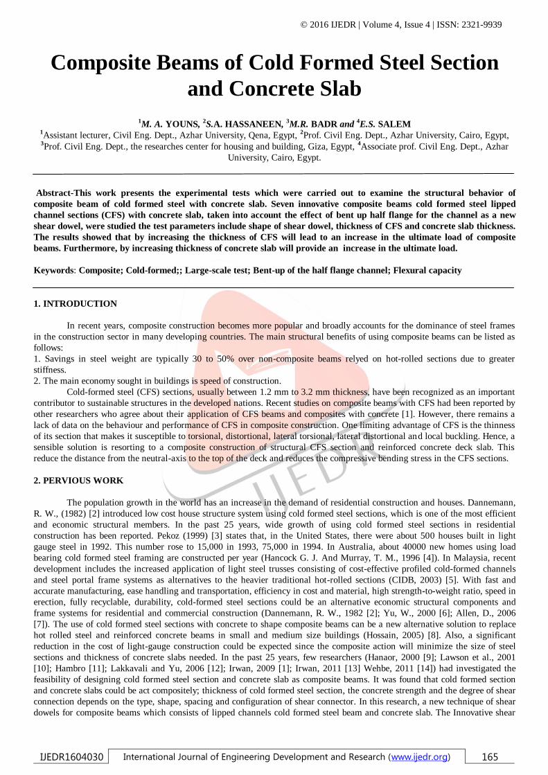
dowel (bent up half flange) is presented to connect the concrete slab and channel steel beam and make the composite action. The
proposed shear dowel is easy to fabricate.
3. THE EXPERIMENTAL PROGRAM
Seven specimens were tested to study the behaviour and capacity of the proposed composite beams. The test parameters
includes shape of shear dowel, concrete slab thickness and CFS thickness. The specimens were tested by using a four-point load
bending test.
3.1. Test specimens
The test specimen is 2 m long and the span between two supports is 1.8 m. The width of the concrete slab is 50 cm. The
CFS is lipped channel (the flange 50 mm wide, web 160 mm height and 20 mm lip). The welded wire fabric reinforcement
consists of 5 mm diameter bar with spacing of 100 mm x 100 mm. The use of wire mesh in the slab has shown higher flexural
stiffness and capacity. To increase the efficiency of the shear connection, a bent-up half flange is suggested as shear dowel as
shown in figure (1). These beams comprise three groups; these groups have different slab thickness and shear dowel shape as
shown in table (1) and figure (2). The first group includes b1, b2 and b3 which have steel thickness 2, 3 and 4 mm respectively,
these specimens have the same floor thickness (60 mm) and shear dowel (bent up to half flange along beam as in figure 1a). The
second group includes b4 and b5 which have steel thickness 3 and 4 mm respectively, these two specimens have the same floor
thickness (80 mm) and shear dowel (bent up to half flange along beam). The third group includes b6 and b7 which have steel
thickness 2 and 3 mm respectively, these two specimens have the same floor thickness (60 mm) and shear dowel (partial bent
up to half flange every 40 cm as in figure 1b).
Table (1): Details of specimens for experimental work.
group Specimen
No.
Slab
thickness
(mm)
Steel
thickness
(mm)
Shape of steel
section
Figure
L1
b1
60
2
1.3
b2 3
b3 4
L2
b4
80
3
b5 4
L3
b6
60
2
b7 3
Figure (1a): Bent-up half flange of channel along beam as shear dowel.
© 2016 IJEDR | Volume 4, Issue 4 | ISSN: 2321-9939
IJEDR1604030 International Journal of Engineering Development and Research (www.ijedr.org) 167
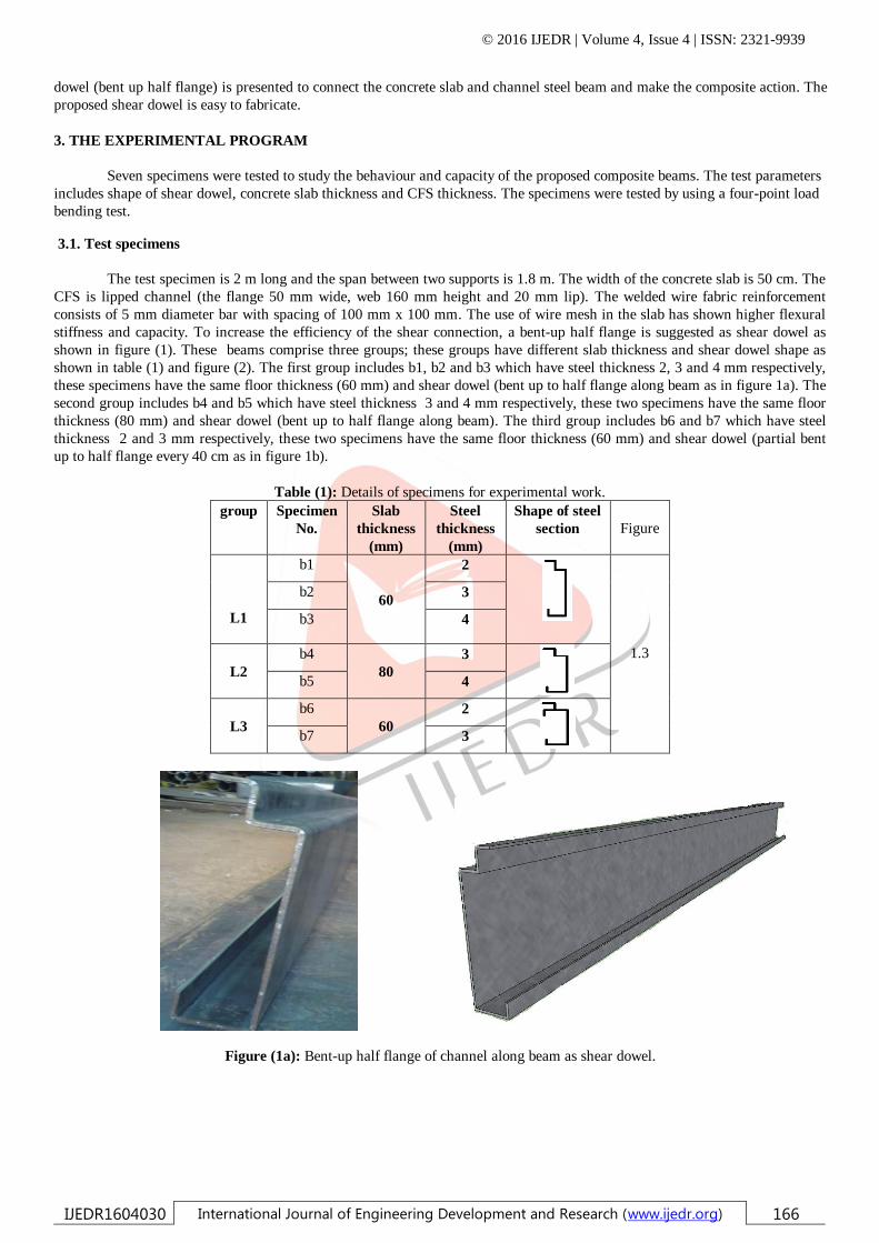
Figure (1b):Partial bent-up half flange of channel as shear dowel.
Figure (2): CFS–concrete composite beam specimen.
3.2. Test setup and procedures
All CFS–concrete composite beams specimens were tested using a Universal Testing Machine subjected to four point
bending test system. Specimens were supported with a pin at one end and a roller at the other end to simulate a simple supported
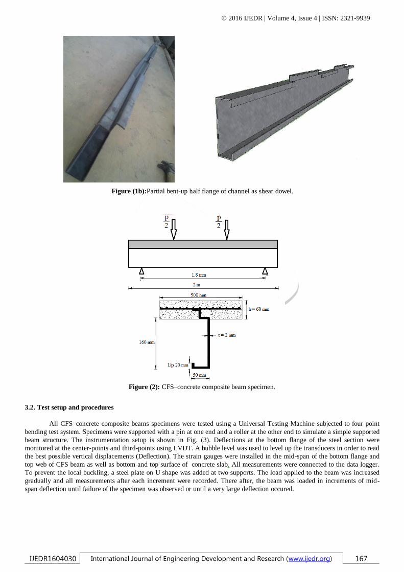
beam structure. The instrumentation setup is shown in Fig. (3). Deflections at the bottom flange of the steel section were
monitored at the center-points and third-points using LVDT. A bubble level was used to level up the transducers in order to read
the best possible vertical displacements (Deflection). The strain gauges were installed in the mid-span of the bottom flange and
top web of CFS beam as well as bottom and top surface of concrete slab. All measurements were connected to the data logger.
To prevent the local buckling, a steel plate on U shape was added at two supports. The load applied to the beam was increased
gradually and all measurements after each increment were recorded. There after, the beam was loaded in increments of mid-
span deflection until failure of the specimen was observed or until a very large deflection occured.
© 2016 IJEDR | Volume 4, Issue 4 | ISSN: 2321-9939
IJEDR1604030 International Journal of Engineering Development and Research (www.ijedr.org) 168
Figure (3): Large-scale test arrangement for composite beam.
3.3. Material properties of specimens
3.3.1 Steel bars and steel plates
Tension tests were performed on three steel bars specimens; also a tension test was carried out on steel plate and Strain
gauge was used to determine the actual stain and Young's modulus in each type. Table (2) gives the mechanical properties of the
reinforcing used and steel plate (CFS) types.
3.3.2 Concrete
The gravel used in this work was local one having specific gravity and volume weight of 2.53 and 1.52 gm/cm3,
respectively and maximum nominal size of 20 mm. Sand from natural sources having a specific gravity 2.63, volume weight and
fineness modulus of 1.73 gm/cm3, 3.19, respectively, were used. Ordinary Portland cement was used in this study, the specific
gravity 3.15, surface area 3200 cm2/gm, initial setting time 2.25hr and final setting time 4.25 hr. The concrete mix was designed
to have a 28 days cubic strength of about 27 N/mm2. The concrete mix proportion is details in table (3). Longitudinal reinforcing
steel and steel plate (CFS) were mild steel of grade 24/35.
Table (2): Mechanical properties of reinforcement steel.
Nominal
diameter
mm
Actual
dia.
mm
Yield stress
(N/mm2)
ultimate stress
(N/mm2) Elongation%
test
result
ESS#
203/2008
test
result
ESS
203/2008 test result
5 4.8 265 240 406 350 na
Steel plate 2*
272 240 381 350 28 %
(*) thickNess of steel plate (CFS)
(#)ESS: Egyption specifications
Table (3): the concrete mix proportion
Gravel kg/m3 Sand kg/m3 Water L/m3 Cement kg/m3
800 400 175 350
For each concrete batch, compressive strength, tensile strength and modulus of elasticity tests were performed on
15*15*15 cm cubes. The average compressive, tensile strength and modulus of elasticity were 27 N/mm2, 3.12 N/mm2 and 23.3
KN/mm2, respectively.
4. ANALYSIS OF EXPERIMENTAL RESULTS
The purpose of the flexural bending test for full scale specimen was to study the behavior of CFS–concrete composite
beams and to determine the efficiency of bent up part of flange of the channel as shear dowel. The results that were sustained
by testing of each specimen are summarized in Table (4).
© 2016 IJEDR | Volume 4, Issue 4 | ISSN: 2321-9939
IJEDR1604030 International Journal of Engineering Development and Research (www.ijedr.org) 169
Table (4): Experimental results of ultimate loads for specimens.
group
Specimen
No.
tf
mm
tsteel
(mm
)
Ultimate
load,
Pu (kN)
Deflection
at Pu, δu
(mm)
Ultimate
moment,
Mu,exp
(kN.m)
Failure mode
L1
b1
60
2 46.1 19.90 13.83 Buckling of CFS
b2 3 73.5 20.10 22.05 Concrete
crushing b3 4 94.7 15.76 28.41
L2
b4
80
3 77.3 16.66 23.19 Concrete
crushing b5 4 130.6 16.39 39.18
L3
b6
60
2 47.3 23.65 14.19 Buckling of CFS
b7 3 81.6 17.79 24.48 Concrete crushing
4.1. Parametric study
4.1.1 Shear dowel enhancements
Testing of specimens in Groups L1 and L3 was carried out to investigate the effect of different types of proposed shear
dowel enhancement in CFS–concrete composite beams. The ultimate loads can be sustained by all specimens are summarized in
Table (4). It was found that a CFS–concrete composite beam specimen with suggested shear dowel enhancements showed an
increase in capacity of ultimate moment. The ultimate capacity of Specimen (b6) (bent up half flange each 40 cm) is 2.6%
higher than that of Specimen (b1) (full bent up half flange). The ultimate capacity of Specimen (b7) (partially bent up half
flange) shows an increase of 11% in the ultimate capacity over Specimen (b2) (full bent up half flange). Therefore, it can be
concluded that the ultimate moment resistance of the CFS–concrete composite beam with partial bent up half flange each 40 cm
is better than the CFS–concrete composite beam with bent up half flange along beam (full bent up of half flange as shear dowel).
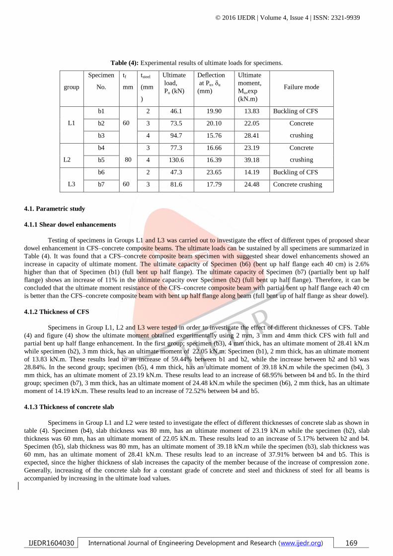
4.1.2 Thickness of CFS
Specimens in Group L1, L2 and L3 were tested in order to investigate the effect of different thicknesses of CFS. Table
(4) and figure (4) show the ultimate moment obtained experimentally using 2 mm, 3 mm and 4mm thick CFS with full and
partial bent up half flange enhancement. In the first group; specimen (b3), 4 mm thick, has an ultimate moment of 28.41 kN.m
while specimen (b2), 3 mm thick, has an ultimate moment of 22.05 kN.m. Specimen (b1), 2 mm thick, has an ultimate moment
of 13.83 kN.m. These results lead to an increase of 59.44% between b1 and b2, while the increase between b2 and b3 was
28.84%. In the second group; specimen (b5), 4 mm thick, has an ultimate moment of 39.18 kN.m while the specimen (b4), 3
mm thick, has an ultimate moment of 23.19 kN.m. These results lead to an increase of 68.95% between b4 and b5. In the third
group; specimen (b7), 3 mm thick, has an ultimate moment of 24.48 kN.m while the specimen (b6), 2 mm thick, has an ultimate
moment of 14.19 kN.m. These results lead to an increase of 72.52% between b4 and b5.
4.1.3 Thickness of concrete slab
Specimens in Group L1 and L2 were tested to investigate the effect of different thicknesses of concrete slab as shown in
table (4). Specimen (b4), slab thickness was 80 mm, has an ultimate moment of 23.19 kN.m while the specimen (b2), slab
thickness was 60 mm, has an ultimate moment of 22.05 kN.m. These results lead to an increase of 5.17% between b2 and b4.
Specimen (b5), slab thickness was 80 mm, has an ultimate moment of 39.18 kN.m while the specimen (b3), slab thickness was
60 mm, has an ultimate moment of 28.41 kN.m. These results lead to an increase of 37.91% between b4 and b5. This is
expected, since the higher thickness of slab increases the capacity of the member because of the increase of compression zone.
Generally, increasing of the concrete slab for a constant grade of concrete and steel and thickness of steel for all beams is
accompanied by increasing in the ultimate load values.
© 2016 IJEDR | Volume 4, Issue 4 | ISSN: 2321-9939
IJEDR1604030 International Journal of Engineering Development and Research (www.ijedr.org) 170
Figure (4): The ultimate moment for the experimental results.
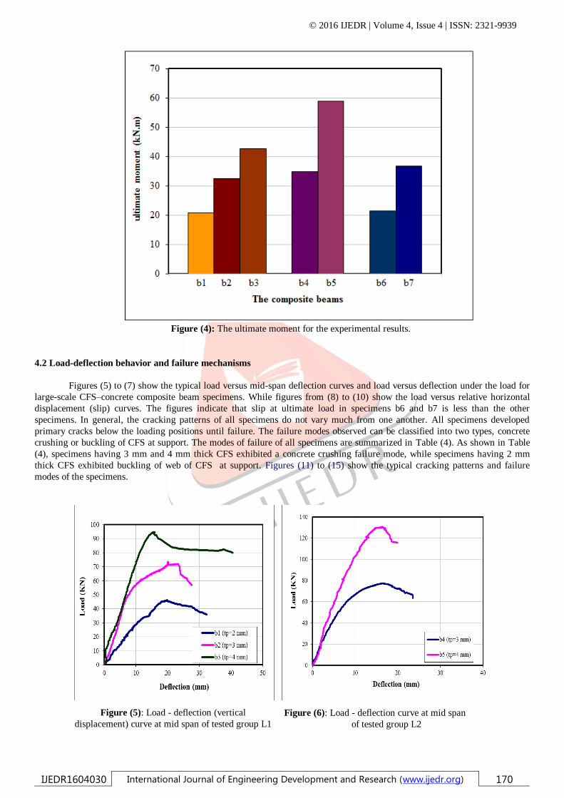
4.2 Load-deflection behavior and failure mechanisms
Figures (5) to (7) show the typical load versus mid-span deflection curves and load versus deflection under the load for
large-scale CFS–concrete composite beam specimens. While figures from (8) to (10) show the load versus relative horizontal
displacement (slip) curves. The figures indicate that slip at ultimate load in specimens b6 and b7 is less than the other
specimens. In general, the cracking patterns of all specimens do not vary much from one another. All specimens developed
primary cracks below the loading positions until failure. The failure modes observed can be classified into two types, concrete
crushing or buckling of CFS at support. The modes of failure of all specimens are summarized in Table (4). As shown in Table
(4), specimens having 3 mm and 4 mm thick CFS exhibited a concrete crushing failure mode, while specimens having 2 mm
thick CFS exhibited buckling of web of CFS at support. Figures (11) to (15) show the typical cracking patterns and failure
modes of the specimens.
Figure (5): Load - deflection (vertical
displacement) curve at mid span of tested group L1
Figure (6): Load - deflection curve at mid span
of tested group L2
© 2016 IJEDR | Volume 4, Issue 4 | ISSN: 2321-9939
IJEDR1604030 International Journal of Engineering Development and Research (www.ijedr.org) 171
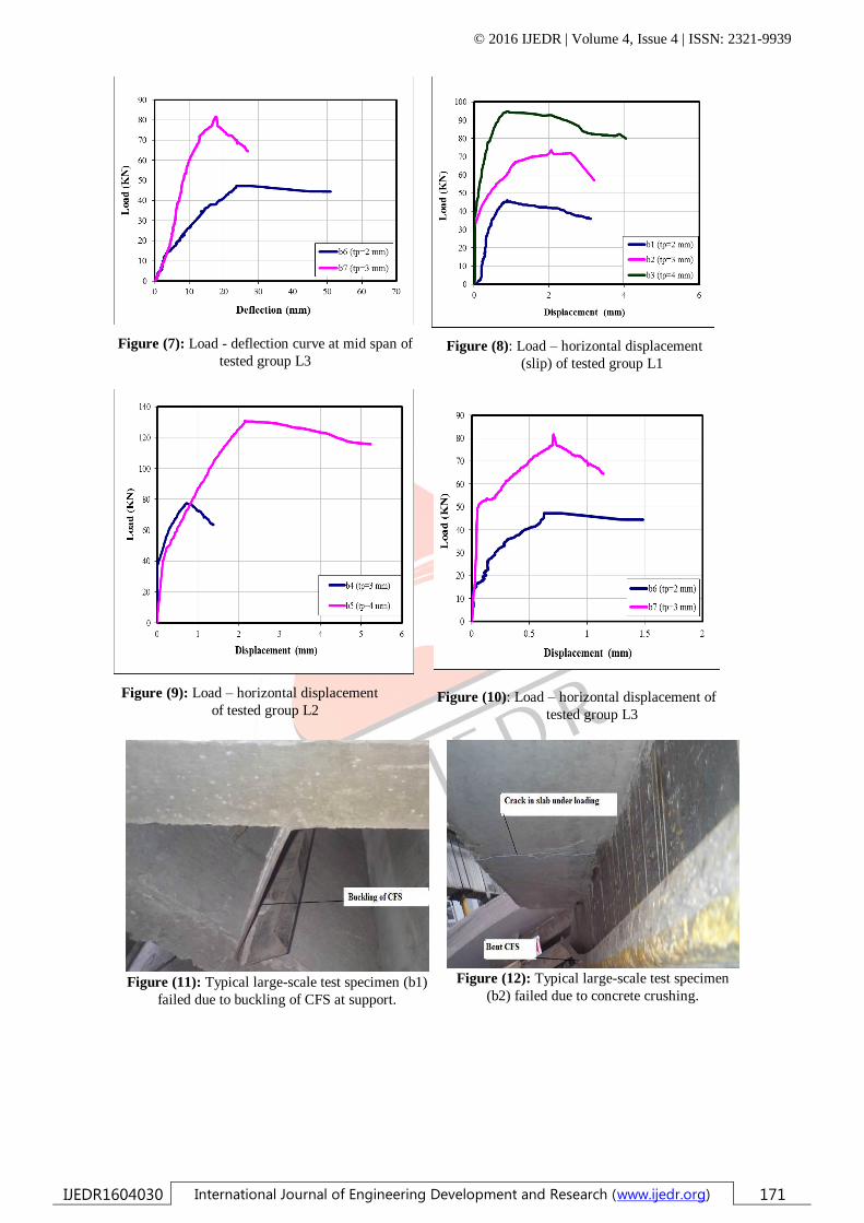
Figure (7): Load - deflection curve at mid span of
tested group L3
Figure (8): Load – horizontal displacement
(slip) of tested group L1
Figure (9): Load – horizontal displacement
of tested group L2
Figure (10): Load – horizontal displacement of
tested group L3
Figure (11): Typical large-scale test specimen (b1)
failed due to buckling of CFS at support.
Figure (12): Typical large-scale test specimen
(b2) failed due to concrete crushing.
© 2016 IJEDR | Volume 4, Issue 4 | ISSN: 2321-9939
IJEDR1604030 International Journal of Engineering Development and Research (www.ijedr.org) 172
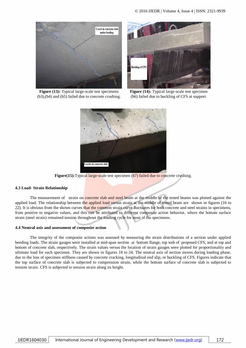
Figure (13): Typical large-scale test specimens
(b3),(b4) and (b5) failed due to concrete crushing.
Figure (14): Typical large-scale test specimen
(b6) failed due to buckling of CFS at support.
Figure(15):Typical large-scale test specimen (b7) failed due to concrete crushing.
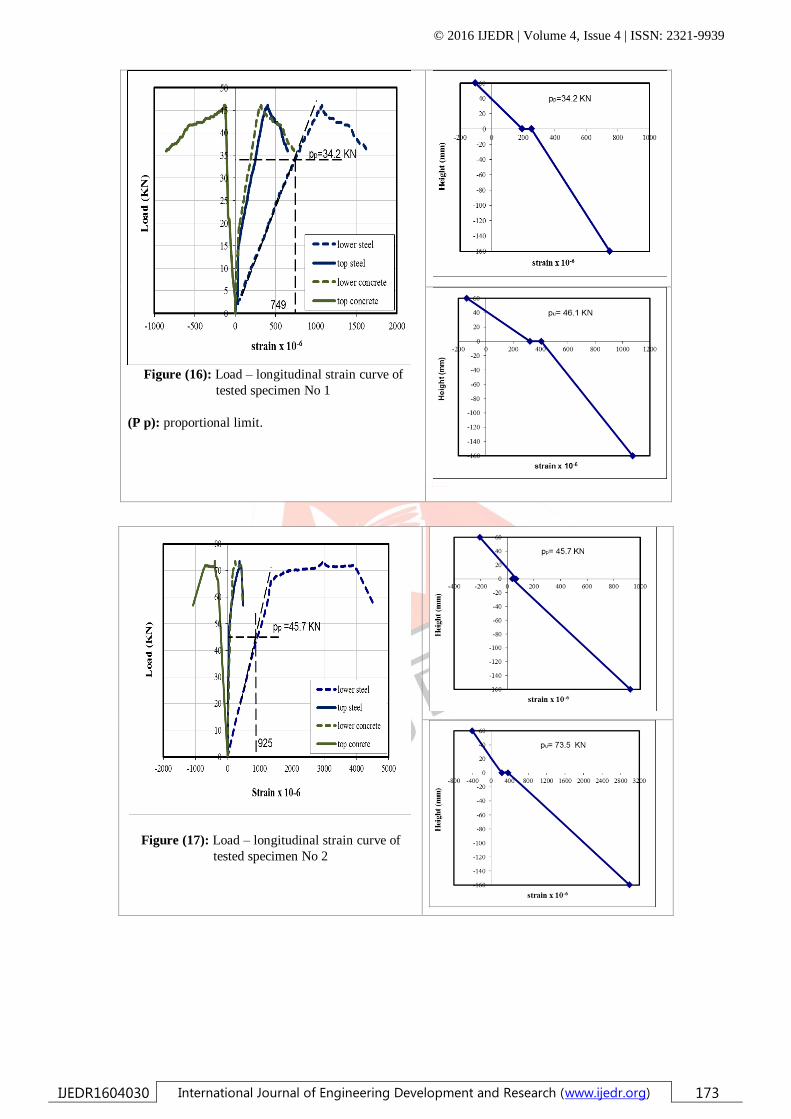
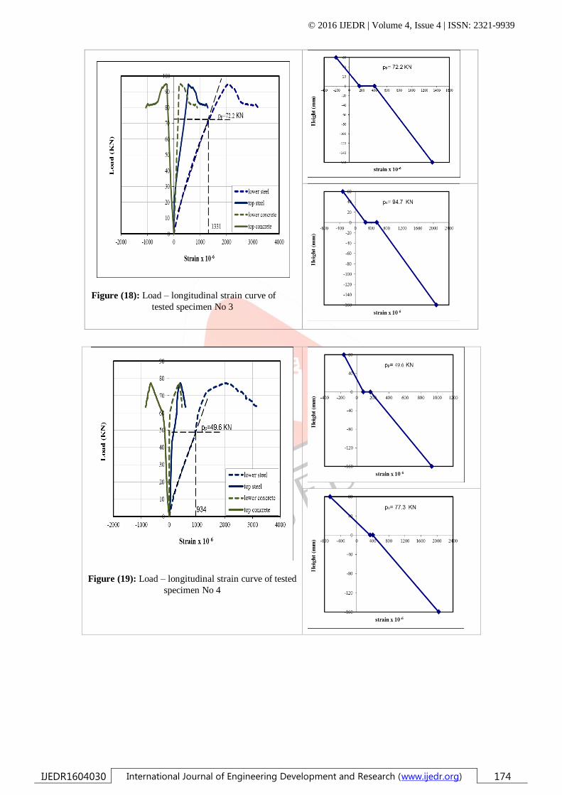
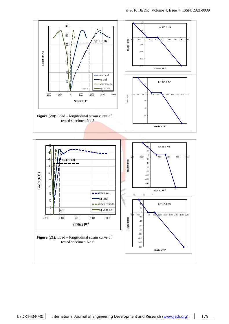
4.3 Load- Strain Relationship
The measurement of strain on concrete slab and steel beam at the middle of the tested beams was plotted against the
applied load. The relationship between the applied load versus strain at the middle of tested beam are shown in figures (16 to
22). It is obvious from the shown curves that the common strain curve fluctuates for both concrete and steel strains in specimens,
from positive to negative values, and this can be attributed to different composite action behavior, where the bottom surface
strain (steel strain) remained tension throughout the loading cycle for most of the specimens.
4.4 Neutral axis and assessment of composite action
The integrity of the composite actions was assessed by measuring the strain distributions of a section under applied
bending loads. The strain gauges were installed at mid-span section at bottom flange, top web of proposed CFS, and at top and
bottom of concrete slab, respectively. The strain values versus the location of strain gauges were plotted for proportionality and
ultimate load for each specimen. They are shown in figures 18 to 24. The neutral axis of section moves during loading phase,
due to the loss of specimen stiffness caused by concrete cracking, longitudinal end slip, or buckling of CFS. Figures indicate that
the top surface of concrete slab is subjected to compression strain, while the bottom surface of concrete slab is subjected to
tension strain. CFS is subjected to tension strain along its height.
© 2016 IJEDR | Volume 4, Issue 4 | ISSN: 2321-9939
IJEDR1604030 International Journal of Engineering Development and Research (www.ijedr.org) 173
Figure (16): Load – longitudinal strain curve of
tested specimen No 1
(P p): proportional limit.
Figure (17): Load – longitudinal strain curve of
tested specimen No 2
© 2016 IJEDR | Volume 4, Issue 4 | ISSN: 2321-9939
IJEDR1604030 International Journal of Engineering Development and Research (www.ijedr.org) 174
Figure (18): Load – longitudinal strain curve of
tested specimen No 3
Figure (19): Load – longitudinal strain curve of tested
specimen No 4
© 2016 IJEDR | Volume 4, Issue 4 | ISSN: 2321-9939
IJEDR1604030 International Journal of Engineering Development and Research (www.ijedr.org) 175
Figure (20): Load – longitudinal strain curve of
tested specimen No 5
Figure (21): Load – longitudinal strain curve of
tested specimen No 6
© 2016 IJEDR | Volume 4, Issue 4 | ISSN: 2321-9939
IJEDR1604030 International Journal of Engineering Development and Research (www.ijedr.org) 176
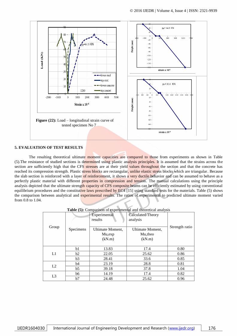
Figure (22): Load – longitudinal strain curve of
tested specimen No 7
5. EVALUATION OF TEST RESULTS
The resulting theoretical ultimate moment capacities are compared to those from experiments as shown in Table
(5).The resistance of studied sections is determined using plastic analysis principles. It is assumed that the strains across the
section are sufficiently high that the CFS stresses are at their yield values throughout the section and that the concrete has
reached its compression strength. Plastic stress blocks are rectangular, unlike elastic stress blocks which are triangular . Because
the slab section is reinforced with a layer of reinforcement, it shows a very ductile behavior and can be assumed to behave as a
perfectly plastic material with different properties in compression and tension. The manual calculations using the principle
analysis depicted that the ultimate strength capacity of CFS composite beams can be efficiently estimated by using conventional
equilibrium procedures and the constitutive laws prescribed by EC4 [15] using standard tests for the materials. Table (5) shows
the comparison between analytical and experimental results. The ratios of experimental to predicted ultimate moment varied
from 0.8 to 1.04.
Table (5): Comparison of experimental and theoretical analysis
Group
Specimens
Experimental
results
Calculated/Theory
analysis
Strength ratio
Ultimate Moment,
Mu,exp
(kN.m)
Ultimate Moment,
Mu,theo
(kN.m)
L1
b1 13.83 17.4 0.80
b2 22.05 25.62 0.86
b3 28.41 33.6 0.85
L2 b4 23.19 28.8 0.81
b5 39.18 37.8 1.04
L3 b6 14.19 17.4 0.82
b7 24.48 25.62 0.96
© 2016 IJEDR | Volume 4, Issue 4 | ISSN: 2321-9939
IJEDR1604030 International Journal of Engineering Development and Research (www.ijedr.org) 177
6. CONCLUSIONS
Based on the results of large-scale slab specimens, the following can be concluded:
1- In general, the cracking patterns of all specimens do not vary from one another and all specimens developed primary
cracks below the loading positions until failure.
2- CFS specimens with thickness of 3 mm and 4 mm exhibited concrete crushing failure mode, while CFS specimens
with thickness of 2 mm exhibited buckling of CFS failure mode at support.
3- CFS–concrete composite beam specimen with proposed shear dowel enhancements showed an increase in capacity of
ultimate moment.
4- Specimen b7 (partial bent up of half flange every 40 cm) shows an increase of 11% in the ultimate capacity over
Specimen b2 (bent up of half flange along beam).
5- Increasing thickness of CFS for constant grade of concrete and steel and thickness of slab for all composite beams is
accompanied by increase in the ultimate moment values by 28% to 73%.
6- Increasing of concrete slab for constant grade of concrete and steel and thickness of steel for all beams is accompanied
by increasing in the ultimate load values by 5% to 38%.
REFERENCES
[1] Irwan, M., Hanizah, A. and Azmi, I. (2009). Test of shear transfer enhancement in symmetric cold-formed steel concrete
composite beams. Journal of Constructional Steel Research, 65(12), 2087-2098.
[2] Dannemann, R. W. (1982). Cold Formed Standard Steel Products In A Low Cost House Construction Method. Sixth
international specialty conference on cold-formed steel structures. St. Louis, Missouri, USA, 653-674..
[3] Pekoz, T. (1999). Possible Future Developments In The Design And Application of Cold-Formed Steel. fourth international
conference. Light-Weight Steel and Aluminium Structures. Espoo, Finland.
[4] Hancock, G. J. and Murray. T. M. (1996). Residential Applications Of Cold·Formed Structural Members In Australia.
Thirteenth International Specialty Conference on Cold-Formed Steel Structures. St. Louis, Missouri, USA, 505-511.
[5] CIDB, (2003). Survey on the usage of Industrialised Building Systems (IBS) in Malaysian Construction Industry. CIDB
Malaysia publication.
[6] Yu, W. W. (2000). Cold-Formed Steel Design. (3rd ed.) New York, John Wiley &Sons, Inc.
[7] Allen, D. (2006). Mid-Rise Construction Detailing issues with Cold-Formed Steel and Compatible Construction Materials.
ASCE, Structures.
[8] Hossain, A. (2005). Designing thin-walled composite-filled beams. Proceedings of the Institution of Civil Engineers,
Structures & Buildings, 158(SB4), 267-278.
[9] Hanaor, A. (2000). Tests of composite beams with cold-formed sections. Journal of Constructional Steel Research, 54(2),
245–264.
[10] Lawson, R. M., Popo-Ola, S. O. and Varley, D. N. (2001). Innovative development of light steel composites in buildings.
In: Eligehausen, R. (ed.) International Symposium on Connections between Steel and Concrete. Stuttgart, Germany RILEM
Publications SARL.
[11] Hambro® Composite Floor Joist Systems (2004). Handbook of Hambro® D500. Hambro®, available from
http://www.hambrosystems.com/.
[12] B. S. Lakkavalli and Y. Liu, 2006. Experimental Study of Composite Cold-formed Steel C section Floor Joists. Journal of
Constructional Steel Research. 62: 995–1006.
[13] J. M. Irwan, A. H. Hanizah, I. Azmi, and H. B. Koh. 2011. Large-scale Test of Symmetric Cold-formed Steel (CFS)–
concrete Composite Beams with BTTST Enhancement. Journal of Constructional Steel Research. 67: 720–726.
[14] Wehbe, N., Wehbe, A., Dayton, L. and Sigl, A. (2011). Development of Concrete/Cold Formed Steel Composite Flexural
Members. Structures Congress, ASCE., 3099-3109.
[15]European Committee For Standardization. (2004) . EN1994-1-1. Brussels: European Committee For Standardization.