
With PE Circuit - Office of Energy Efficiency & Renewable Energy
36
Thermoelectric Conversion of Waste Heat to Electricity in an IC Engine Powered Vehicle Principal Investigator: Harold Schock Prepared by: Harold Schock, Eldon Case, Jonathan D’Angelo, Andrew Hartsig, Tim Hogan, Mercouri Kanatzidis, James Novak, Fang Peng, Fei Ren, Tom Shih, Jeff Sakamoto, Todd Sheridan, Ed Timm 08/15/2007 Supported By: Acknowledgement: ONR support US Department of Energy under MURI Program Energy Efficiency Renewable Energy (EERE) Mihal Gross, Project Monitor John Fairbanks and Samuel Taylor, Contract Monitors IOWA STATE UNIVERSITY
Transcript of With PE Circuit - Office of Energy Efficiency & Renewable Energy

Thermoelectric Conversion of Waste Heat to Electricity in an IC Engine Powered Vehicle
Principal Investigator: Harold Schock
Prepared by:Harold Schock, Eldon Case, Jonathan D’Angelo, Andrew Hartsig, Tim Hogan,
Mercouri Kanatzidis, James Novak, Fang Peng, Fei Ren,Tom Shih, Jeff Sakamoto, Todd Sheridan, Ed Timm
08/15/2007
Supported By: Acknowledgement: ONR support US Department of Energy under MURI Program Energy Efficiency Renewable Energy (EERE) Mihal Gross, Project Monitor John Fairbanks and Samuel Taylor, Contract Monitors
IOWA STATE
UNIVERSITY

Implementation of a Thermoelectric Generator with a Cummins ISX Over-the-Road Powerplant
Engine-TEG Simulation and Experimental Verification
MSU / Cummins
• Complete engine system- f(x,t)
• Temperatures and heat flux
• EGR energy
• Energy in exhaust (T, P, m)
• Turbine work, inlet/outlet temperatures
3D CFD Analysis
Iowa State / MSU
• Couple and Module Issues Convection and radiation between
legs with and without insulation Current distribution, Joule heating,
Heat fluxes
• Electrical energy production
• Unsteady heat transfer analysis to and from modules (3D, pulsatile, comp.)
TEG Design and Construction
MSU/JPL
• Generator design • TEG materials selection • Mechanical and TE material propertycharacterization including Weibullanalysis • FEA analysis • Leg and module fabrication methods
6 Cyl. Engine Test Data
Cummins
P2 - Single cylinder +TEG Demo
MSU
Systems for Utilizationof Electrical Power Recovered
MSU
• Design of electrical energy conditioning and utilization system
• Control system design and construction
• Inverter, Belt Integrated Starter-Generator Selection

Goals and ObjectivesGoals and Objectives� Using a TEG, provide a 10% improvement in fuel
economy by converting waste heat to electricity used by the OTR truck
� Evaluate currently available thermoelectric materials to determine optimum material selection and segmentation geometry for this application
� Develop TEG fabrication protocol for module and system demonstration
� Determine heat exchanger requirements needed for building TEGs of reasonable length
� Determine power electronic/control requirements � Determine if Phase 2 results make an engine demo
in Phase 3 reasonable

Important BarriersImportant Barriers• Design of heat exchanger is a major challenge with heat
transfer coefficients needed which are 5x higher than withoutenhanced heat transfer modes
• Reliable thermoelectric module fabrication methods need to be developed for the new high efficiency TE materials
• Material strength and thermoelectiric properties must meet lifecycle performance criteria
• Powder processing methods are being refined to provideincreased strength while maintaining thermoelectric propertiesof ingot forms of the material
• ZT for the temperature ranges (700K) for last material areabout 1.5 and need to be closer to 3.0 to reach the efficiencygoals requested by DOE

Accomplishment to dateAccomplishment to date� Systems for ingot synthesis and leg preparation demonstrated
� March 07, 100 ton hot press operational at MSU (up to a 10 cm puck) � Tube furnaces and leg cutting equipment operational (500 grams/batch) � Segmented legs demonstrated by Sakamoto at JPL (now at MSU)
� Segmented leg - module fabrication methods being developed� Sakamoto at JPL demonstrated segmented p-leg with 14.5% efficiency � Hogan group fabricated and tested numerous LAST/LASTT modules � Diffusion bonding of stainless steel to LAST and BiTe demonstrated
� Power electronic module isolation methods designed andbeing tested at MSU
� Transport measurements conducted by MSU have beenverified by Northwestern, JPL, Iowa State and the generalliterature
� Sublimation issues appear to be under control with aerogelcoatings developed by Sakamoto at JPL and Fortifax at MSU
� Analytical studies performed for various operation modes andconditions � Geometries for high efficiency heat transfer rates evaluated � Efficiency improvements for various operational modes for the Cummins
ISX engine evaluated for various geometries
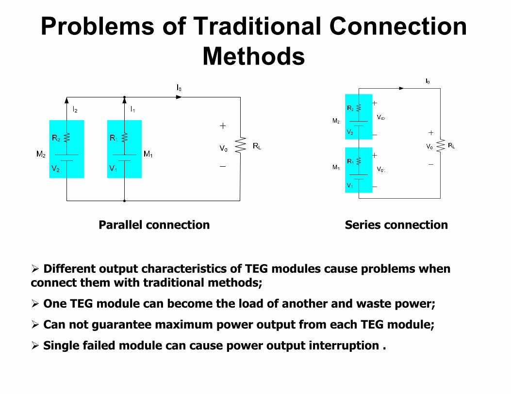
Problems of Traditional Connection Methods
Parallel connection Series connection
¾ Different output characteristics of TEG modules cause problems when connect them with traditional methods;
¾ One TEG module can become the load of another and waste power;
¾ Can not guarantee maximum power output from each TEG module;
¾ Single failed module can cause power output interruption .

Power Electronics for TE Generation
Developing power electronic circuit as an interface between TEG module and load with the features of:
¾ Load matching; ¾ Power conditioning; ¾ Maximum power point tracking; ¾ Failed TEG module bypassing.
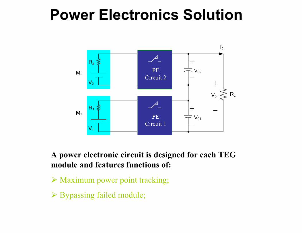
Power Electronics Solution
A power electronic circuit is designed for each TEG module and features functions of:
¾Maximum power point tracking;
¾ Bypassing failed module;

PECircuit 2
PECircuit 2
PECircuit 2
PECircuit 2
To Achieve High Power Output
RLV0
I0
Vn
Rn
V1
R1
V0nMn
M1
PE Circuit n
PE Circuit 1
V01
Vn
Rn
V1
R1
V0n
Mn
M1
PE Circuit n
PE Circuit 1
V01
¾ High power output can be achieved by series-parallel connection of TEG modules;
¾ Power electronic circuits guarantee each TEG module output its maximum power;
¾ Failed modules will not effect the operation of other modules.

TEG module and Heat Exchanger Heatsink
TEG modules
TEG module from Tellurex®
Heat elements
AssemblyOutput characteristics (Tellurex®)
¾ A heat exchanger capable of 100 W electrical power output has been fabricated and Tested.
Our test results
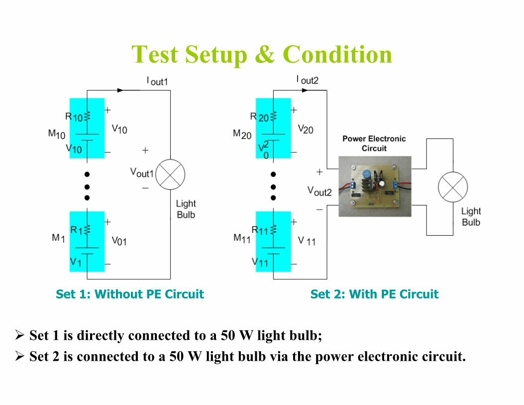
Test Setup & Condition
Set 1: Without PE Circuit Set 2: With PE Circuit
¾ Set 1 is directly connected to a 50 W light bulb; ¾ Set 2 is connected to a 50 W light bulb via the power electronic circuit.

Demo and Test Results of the PE Circuit for Maximum Power Point Tracking
TEG output electric power vs ∆T
0
5
10
15
20
25
30
35
40
45
50
30 50 70 90 110 130
ΔT=T (Hot)−T (Cold) (degree C)
TEG
Out
put P
ower
(W)
W/O PE circuit With PE circuit
¾ The PE circuit can extract the maximum electrical power from the TE modules and feed any electric loads regardless of TE module’s heat flux and load impedance/conditions.
W/O PE circuit
with PE circuit TEG maximum power

Device level efficiency projections:Skutterudite+heritage materials
CeFe3.5Co0.5Sb12 p-leg n-leg
700C
100C
CoSb3
TAGS LAST or PbTe
Option 1: LAST for cold stage of n-leg (525C interface) = 14.80% efficiency
Option 2: PbTe for cold stage of n-leg (438C interface) = ~12.4% efficiency
Option 3: PbTe for cold stage of n-leg (525C interface + TAGS at 500C) = 13.0% efficiency
SOA: Heritage TAGS & PbTe 450C-100C = 8% efficiency

Device details & power outputOption 3: PbTe for cold stage of n-leg (525C interface + TAGS at 500C) = 13.0% efficiency
CeFe3.5Co0.5Sb12 p-leg n-leg
700C
100C
CoSb3
TAGS PbTe
•0.5cm long legs 0.5cm2 each leg
•1 gram (total) for each couple
•2.2 mOhm per couple
•0.127 mV at peak load
•41 amps
•5.2W output
•Assumes 40W/cm2
•200 couples in series at 25V (6” by 6” footprint including gaps) = 1040W

MSU53 Power Output Validation @ JPLMSU53 Power Output Validation
0 10 20 30 40 50 60 70 80 90
100
Pote
ntia
l (m
V)
2.74 mΩ
2.93 mΩ
3.03 mΩ 800700 500C600 635C500400300
Pow
er (m
W)
700C
700C
200 100 0 -100 -200
0 5 10 15 20 25 30
Current (Amps)
•Resistance is within ~1% of predicted value
•14.57% conversion efficiency!

Cummins ISX 6 cylinder diesel engine

Σ
Induction Intercooler
EGR CoolerTEG-1
Thermal Power Split Hybrid – OptionsUsing the electric power recovered from waste heat
X % of exhaust to EGR, (100-X) % of exhaust to turbine.
Additional energy recovery opportunity
ηINV= 0.96 ηBIMG=0.93
Cool Exhaust Out ηmi= 0.89
Pm=249+TEG@ 100%, TEG@ 62%
I E
Wheels FD
Trans.
C
T
Induction Air
EGR
EGR Mixer
ESS, Batt + Ultra-Cap
Th , qh
Pe @62% = Y kW Pe @ 100%= Z kW
Pow
er E
lect
30 -
50 k
VA
WP
Engine Coolant
Air
Exhaust
Coolant Pump
Rad
iato
r
B-I
MG
Excess Electrical Power
T/C or clutch
Powered Ancillaries
TEG-2

Single TEG with exploded view of a module
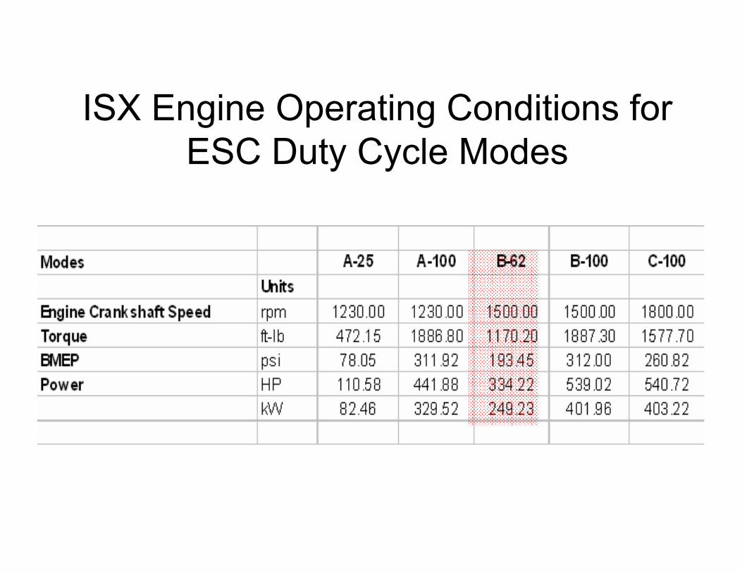
ISX Engine Operating Conditions for ESC Duty Cycle Modes

cold
Issues: hot
Heat Exchanger (HX) • How to fully utilize the hot &
cold
cold temperature sources as efficiently and compactly as possible.
Heat Transfer in the TE Couple • TE cavity: inert gas/insulation • TE legs RC TH
Durability and Life • thermal stress
considerations
J J
x RC TC
J J
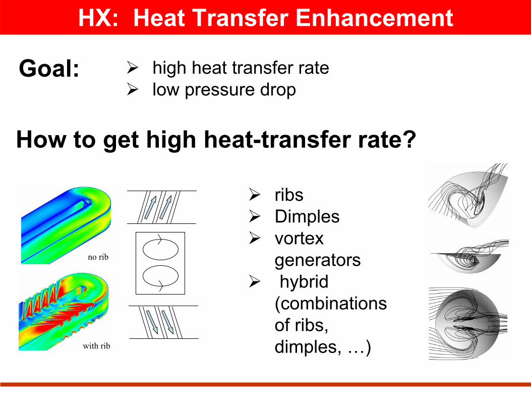
HX: Heat Transfer Enhancement
Goal: ¾ high heat transfer rate ¾ low pressure drop
How to get high heat-transfer rate?
¾ ribs ¾ Dimples ¾ vortex
generators ¾ hybrid
(combinations of ribs, dimples, …)with rib
no rib

Guiding Principle for HT Enhancement
¾ Increase streamwise vorticity / recirculating flow to increases surface heat transfer
Why?Brings hotter & higher momentum fluid in the “core” to the surface.
¾ Interrupting the streamwise recirculating flow periodically is needed (i.e., restart boundary layer).
¾ Induce unsteadiness as another mechanism to restart boundary layer.
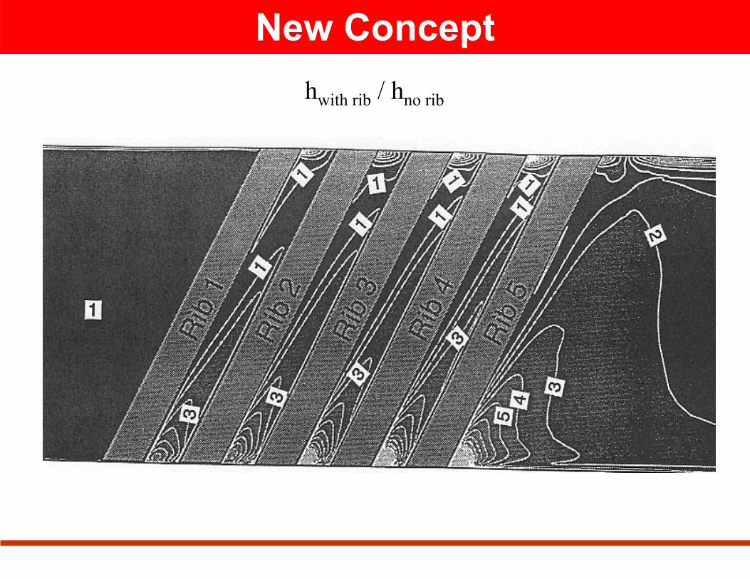
New Concept hwith rib / hno rib

TEG for Waste Heat from IC Engines
T2 T2' T3 T3' Outlet 6-1 731 727 524 342
Midpoint 6-1 781 777 546 338 Inlet 6-1 831 826 567 334
Outlet EGR Cooler 495 493 408 331 Midpoint EGR Cooler 636 633 474 331
Inlet EGR Cooler 834 829 568 334
TEG Configuration
Inlet Midpoint Outlet
1
2
2’
3
3’
radial
axial
Heat flux
Outer wall
Inner wall
Temperature
n p n pn p… …
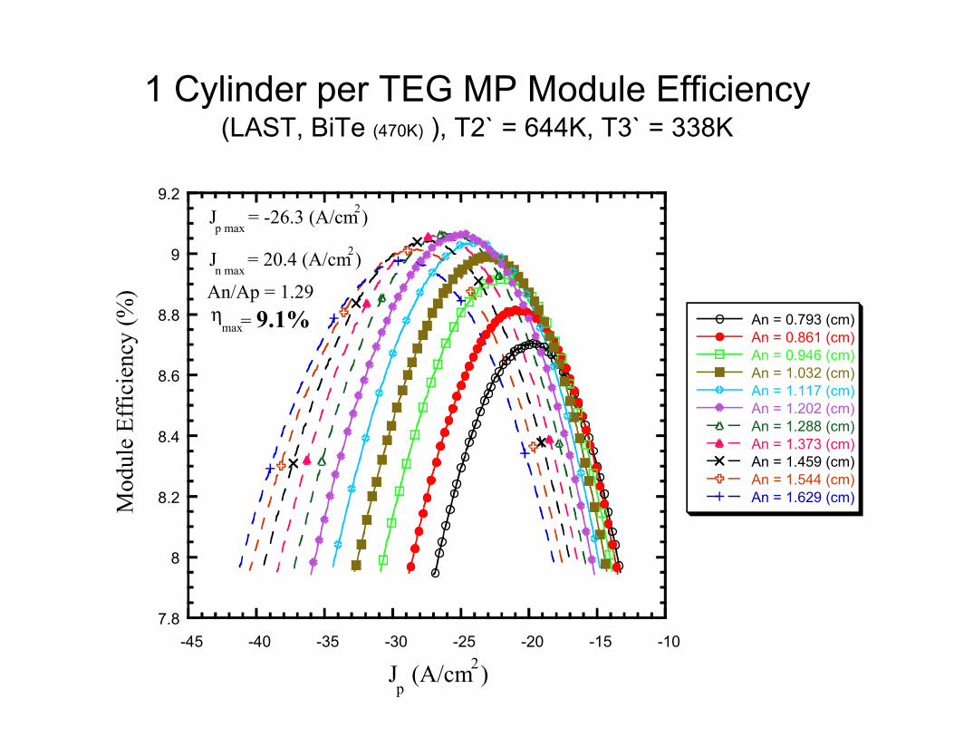
1 Cylinder per TEG MP Module EfficiencyM
odul
e Ef
ficie
ncy
(%)
(LAST, BiTe (470K) ), T2` = 644K, T3` = 338K
9.2 J = -26.3 (A/cm2)p max
9 J = 20.4 (A/cm2)n max
An/Ap = 1.29 8.8 η = 9.1%max
8.6
8.4
8.2
8
7.8 -45 -40 -35 -30 -25 -20 -15 -10
J (A/cm2)p
An = 0.793 (cm) An = 0.861 (cm) An = 0.946 (cm) An = 1.032 (cm) An = 1.117 (cm) An = 1.202 (cm) An = 1.288 (cm) An = 1.373 (cm) An = 1.459 (cm) An = 1.544 (cm) An = 1.629 (cm)

Fuel economy of ISX Engine Operating at Cruise (B62 Point) – Phase I Work
TEG Placed at Head in Exhaust Port
% Imp. In BSFC * = QTEG ⋅ NTEG ⋅ηTEG ⋅ηBISG ⋅η INV
BHP ⋅0.746
1 Cylinder into 1 TEG (6TEGs) = 31.9(6)(0.091)(0.96)(0.93) = 6.2% 334.6 ⋅0.746
3 Cylinders into 1 TEG (2 TEGs) = 50.2(2)(0.11)(0.96)(0.93) = 4.0% 334.6 ⋅0.746
6 Cylinders into 1 TEG (1TEG) = 64.5(1)(0.123)(0.96)(0.93) = 2.8% 334.6 ⋅ 0.746
Note: This does not include improvement in BSFC by utilizing an ISG which has an efficiency 2x that of current alternators or the higher TEG efficiencies at higher load operation
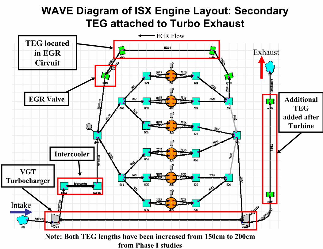
WAVE Diagram of ISX Engine Layout: Secondary TEG attached to Turbo Exhaust
TEG located in EGR Circuit
VGT Turbocharger
Intercooler
Intake
Exhaust
EGR Flow
EGR Valve Additional TEG
added after Turbine
Note: Both TEG lengths have been increased from 150cm to 200cm from Phase I studies
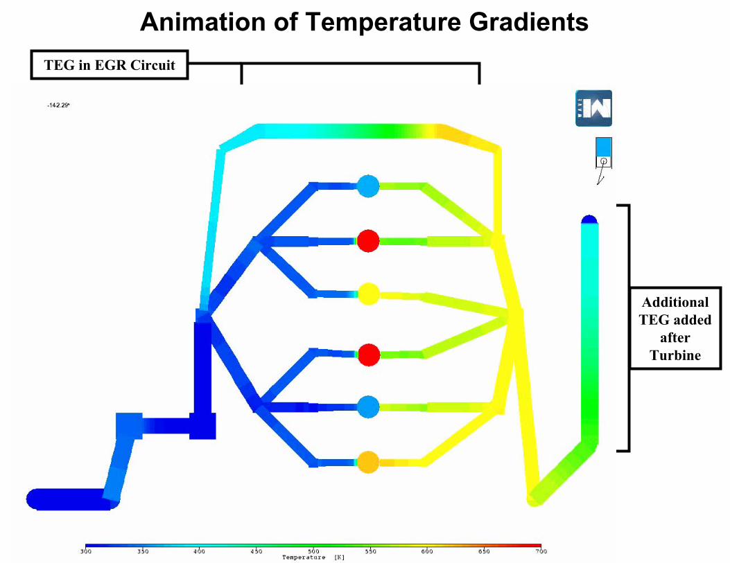
Animation of Temperature Gradients
TEG in EGR Circuit
Additional TEG added
after Turbine

BSFC % Improvement: Single TEG EGR Cooler and Dual TEG
0.0
0.5
1.0
1.5
2.0
2.5
3.0
3.5
4.0
A-25 A-100 B-62 B-100 C-100
Operating Point
% Im
prov
emen
t
Dual TEG: EGR Cooler & After Turbine Single EGR Cooler TEG

Collaborations/InteractionsCollaborations/Interactions
• MSU, JPL, Tellurex, Northwestern, Iowa State and Cummins Team continue to partner in this effort
• Office of Naval Research sponsored effort has provided the basis for new material exploration and assisted in module fabrication developments
• Oak Ridge DOE (High Temperature Materials Laboratory) has provided significant assistance in material property characterization

Publications/PatentPublications/Patent• Characterization of dry milled LAST (Lead-Antimony-Silver-Tellurium)
thermoelectric material, Pilchak, A., Ren, F., Case, E., Timm, E. and Schock, H., submitted to Philosophical Magazine, Spring 07
• Nanostructured Thermoelectric Materials and High Efficiency PowerGeneration Modules, Hogan, T., Downey, A., Short, J. et al., prepared spring07
• The Young’s modulus and Poisson’s ratio of lead-telluride basedthermoelectric materials as a function of temperature, Ren, F., Case, E., Timm, E., Schock, H., Lara-Cuzio, E., Trejo, R., Lin, C.H.,Kanatzidis, M., submitted to International Journal of Applied Ceramics Technology, Spring, 07
• Hardness as a function of composition for n-type LAST thermoelectric materials, F. Ren, E.D. Case, E.J. Timm, and H.J. Schock, Journal of Alloysand Compounds, (2007) doi:10.1016/jallcom.2007.01.086
• Young’s modulus as a function of composition of n-type lead-antimony-silver-telluride (LAST) thermoelectric materials, F. Ren, E.D. Case, E.J. Timm, and H.J. Schock, submitted to Philosophical Magazine, Spring 07
• Weibull analysis of the biaxial fracture strength of a cast p-type LAST-Tthermoelectric material, F. Ren, E.D. Case, E.J. Timm, M.D. Jacobs and H.J. Schock, Philosophical Magazine Letters, Vol. 86, No. 10, Oct. 2006, 673-682

Plans for the Rest of the YearPlans for the Rest of the Year
� July ~ Aug, 2007: Modules being fabricated, segmented concepts testing and powder processing method development ongoing
� Aug ~ Dec. 2007 Evaluation of new TE systems and stoichiometries � Sept ~ Dec. 2007 Demonstrate power electronics for 100 watt TEG � Aug ~ Nov, 2007: High efficiency module construction and performance
testing � Sept ~ Nov, 2007: Design of heat exchanger and numerical simulation of
expected system performance � Dec, 2007: Preparing quarterly project report

SummarySummary• Systems for material synthesis, powder processing, hot pressing,
leg and module fabrication are operational at MSU • Facility in place to produce materials required for a 40 watt
module in one week …thus new concepts can be evaluated inabout one week
• Thermoelectric performance testing of legs and modules at MSUis in agreement with others doing similar measurements
• Power conditioning electronics for maximum power tracking andfault mitigation are being tested
• Improved head exchanger designs are critical to success of TEeffort for waste heat recovery
• Using TEG technology, a 5% improvement in bsfc for and OTR truck is a reasonable 5 year goal …10% improvement possiblewith new TE materials

leg
5mm
MSU53: Metallized (end-end) Segmented pSKD+TAGS
•Test set up for validating power output of pSKD/TAGS segmented leg

Res
ista
nce
( μΩ
)2000
MSU 53 Contact Resistance Measurement 1800
NOTE: 4A with 89% efficiency 1600
pSKD1400
0.538mΩ cm-1200 metallization measured 4200 1000 4100
800 0.797mΩ cm-measured
600 TAGS 400
Con
tact
Res
ista
nce
(mic
ro O
hms/
cm2) 4000
3900
3800 ~170 μΩ/cm2 3700
3600
3500
3400
200
0
3300
3200 3700 3900 4100 4300 4500 4700 4900 5100 5300 5500
Distance (microns)
0 2000 4000 6000 8000
Distance (μm) •Contact resistance measured using new 100nm step scanning probe
•Measured resistivity of TAGS & pSKD within +/- 2% of published data
•Contact resistance at segmented interface is low and can be reduced by reducing thickness of metallurgical bond

uncoated uncoated aerogel coated aerogel coated
Goal = 2 x 10⁻⁶
TAGS Sublimation at 535C
1.00E-06
1.00E-05
1.00E-04
0 100 200 300 400 500 600 700 800 time (hours)
Subl
im at
ion
rate
(g/c
m2 h)
�Aerogel suppressed sublimation by a factor of 10 and is approaching the 10years of operation goal at 535C


![[PPT]Chapter 18 Renewable Energy 18-1 Renewable …environmentalscienceclass.weebly.com/.../ch_18_notes.ppt · Web viewChapter 18 Renewable Energy 18-1 Renewable Energy Today Renewable](https://static.fdocuments.us/doc/165x107/5b029fb97f8b9a6a2e900bdf/pptchapter-18-renewable-energy-18-1-renewable-envir-viewchapter-18-renewable.jpg)