Warm_Up What were the three schools of the Aztecs? What did they teach?
Upload
delphine-genouvrierCategory
view
106download
1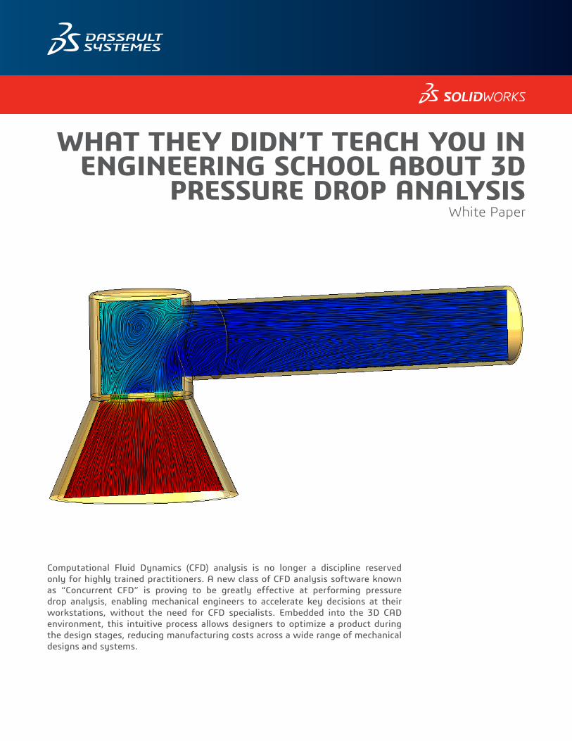
WHAT THEY DIDN’T TEACH YOU IN ENGINEERING SCHOOL ABOUT 3D
PRESSURE DROP ANALYSISWhite Paper
Computational Fluid Dynamics (CFD) analysis is no longer a discipline reserved only for highly trained practitioners. A new class of CFD analysis software known as “Concurrent CFD” is proving to be greatly effective at performing pressure drop analysis, enabling mechanical engineers to accelerate key decisions at their workstations, without the need for CFD specialists. Embedded into the 3D CAD environment, this intuitive process allows designers to optimize a product during the design stages, reducing manufacturing costs across a wide range of mechanical designs and systems.
Flow Pressure Drop: What They Didn’t Teach You in Engineering School about 3D Pressure Drop Analysis
Until recently, the commercial software available for CFD has typically been geared towards specialists, limiting its widespread use. Besides being expensive, these tools have either been difficult, cumbersome or time-consuming to use. As a result, engineering analysis for applications such as pressure drop traditionally have been carried out by specialists in analysis departments, separate from mainstream design and development departments or through costly physical prototyping only for some critical products.
To test or verify their designs, mechanical engineers therefore had to rely on creating physical prototypes and testing them on a flow bench or test rig. But this labor-intensive approach often led to incomplete results, limited to readings at discrete locations, making it difficult to thoroughly understand and characterize the underlying flow.
Fortunately, new tools have emerged that embed a complete range of flow and heat transfer analyses including pressure drop simulation within mainstream 3D CAD toolsets such as SOLIDWORKS® design software. The SOLIDWORKS Flow Simulation CFD analysis technology is aimed specifically at the mechanical design engineer. With SOLIDWORKS Flow Simulation there is no need to hire or train CFD specialists, outsource analysis to consultants, or conduct tests on expensive multiple physical prototypes.
Instead, a design engineer with standard training, working in any size company, can use his or her existing knowledge to successfully perform pressure drop analyses, entirely within today’s familiar 3D CAD environment SOLIDWORKS. SOLIDWORKS Flow Simulation can improve design productivity and may dramatically reduce the number of physical prototypes needed. Equally important, it encourages engineers to explore many more ‘what-if’ scenarios to perfect their designs.
Certainly there will always be a few very demanding applications where more advanced CFD knowledge is needed to fine-tune the meshing and solver settings in order to converge to a solution. But taking CFD out of the exclusive domain of specialists and bringing it into the mainstream with SOLIDWORKS Flow Simulation enables product engineers without specific training in CFD to analyze problems in about 80 to 90 percent of all cases. This amounts to a fundamental breakthrough in design efficiency.
Flow Pressure Drop: What They Didn’t Teach You in Engineering School about 3D Pressure Drop Analysis
PRESSURE DROP ANALYSIS IN THE 3D CAD ENVIRONMENTSOLIDWORKS Flow Simulation CFD simulation software combines all phases of pressure drop analysis in one package, from solid modelling with SOLIDWORKS CAD, to problem set-up, running, results visualization, validation, and reporting. Typical pressure drop applications include flows through valves, manifolds, heat exchangers, filtration systems, electronics enclosures and ducting; in fact any system where the goal is to reduce the amount of energy required to move flow or to maximize its capacity.
With SOLIDWORKS Flow Simulation, designers can focus on analyzing, in detail, why the flow of gas or liquid may be at a higher or lower pressure than that allowed in the technical specification. They can run ‘what-if’ scenarios and then optimize their design’s geometry within SOLIDWORKS. All the designer needs is knowledge of the 3D CAD system and the physics of the product. After installation of SOLIDWORKS Flow Simulation, all of the menus and commands necessary to run a full CFD flow analysis are created in the SOLIDWORKS menu system. This full integration between the 3D CAD system and SOLIDWORKS Flow Simulation makes it extremely easy to use. In fact, most designers are ready to use SOLIDWORKS Flow Simulation with less than eight hours of training.
The most common engineering task for fluid flow applications is to minimize the pressure losses in a system as a fluid flows from point A to point B. The basic engineering challenge is to either maximize the flow rate for a given pressure drop or minimize the pressure drop for a given flow rate. If the flow is driven by a pump or fan, then understanding the pressure drop enables the designer to optimize the size of the fan or pump.
The starting point of any flow analysis is to clearly describe the geometry of the mechanical system. SOLIDWORKS Flow Simulation lets a designer take advantage of existing CAD models for analysis, without having to export or import additional data, saving significant amounts of time and effort. There is no need to create a separate model of the fluid region, a tedious process in traditional CFD tools. SOLIDWORKS Flow Simulation recognizes the appropriate fluid region based on the empty internal spaces within the solid model, where the designer has placed boundary conditions.
SOLIDWORKS Flow Simulation can also analyze a range of fluids. This includes gases—starting with the subsonic regime up through transonic and supersonic flow—liquids and non-Newtonian fluids such as plastic flows, as well as flows for food processing applications.
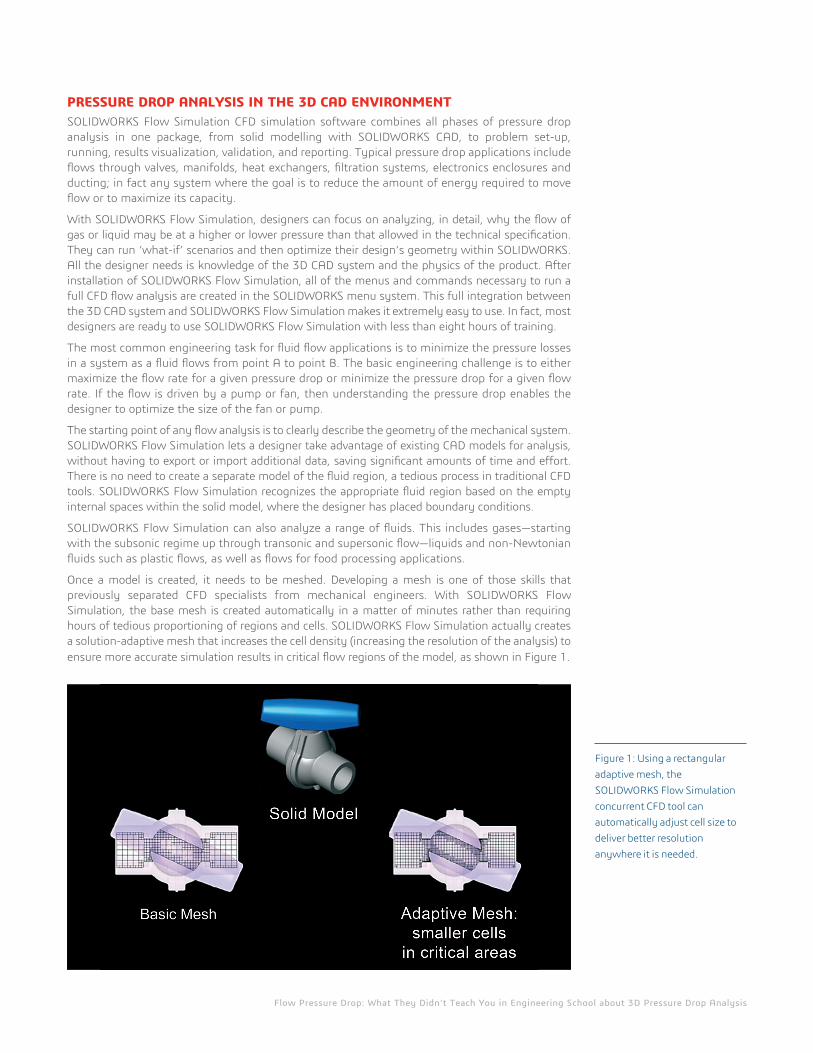
Once a model is created, it needs to be meshed. Developing a mesh is one of those skills that previously separated CFD specialists from mechanical engineers. With SOLIDWORKS Flow Simulation, the base mesh is created automatically in a matter of minutes rather than requiring hours of tedious proportioning of regions and cells. SOLIDWORKS Flow Simulation actually creates a solution-adaptive mesh that increases the cell density (increasing the resolution of the analysis) to ensure more accurate simulation results in critical flow regions of the model, as shown in Figure 1.
Figure 1: Using a rectangular adaptive mesh, the SOLIDWORKS Flow Simulation concurrent CFD tool can automatically adjust cell size to deliver better resolution anywhere it is needed.
Flow Pressure Drop: What They Didn’t Teach You in Engineering School about 3D Pressure Drop Analysis
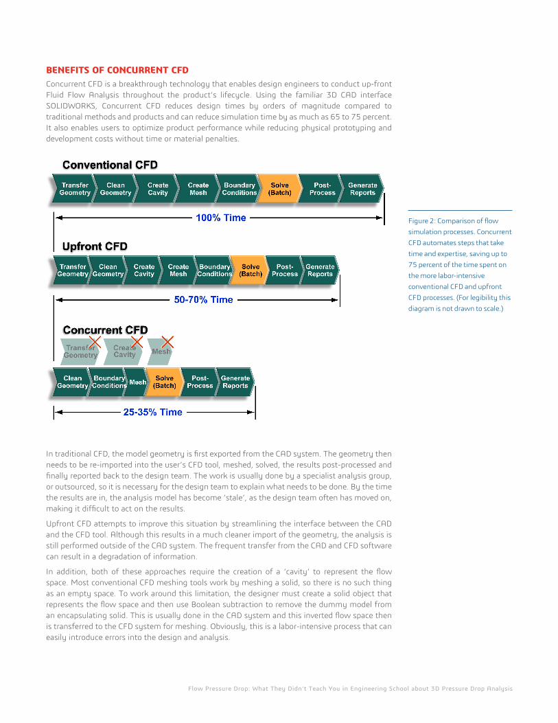
BENEFITS OF CONCURRENT CFDConcurrent CFD is a breakthrough technology that enables design engineers to conduct up-front Fluid Flow Analysis throughout the product’s lifecycle. Using the familiar 3D CAD interface SOLIDWORKS, Concurrent CFD reduces design times by orders of magnitude compared to traditional methods and products and can reduce simulation time by as much as 65 to 75 percent. It also enables users to optimize product performance while reducing physical prototyping and development costs without time or material penalties.
In traditional CFD, the model geometry is first exported from the CAD system. The geometry then needs to be re-imported into the user’s CFD tool, meshed, solved, the results post-processed and finally reported back to the design team. The work is usually done by a specialist analysis group, or outsourced, so it is necessary for the design team to explain what needs to be done. By the time the results are in, the analysis model has become ‘stale’, as the design team often has moved on, making it difficult to act on the results.
Upfront CFD attempts to improve this situation by streamlining the interface between the CAD and the CFD tool. Although this results in a much cleaner import of the geometry, the analysis is still performed outside of the CAD system. The frequent transfer from the CAD and CFD software can result in a degradation of information.
In addition, both of these approaches require the creation of a ‘cavity’ to represent the flow space. Most conventional CFD meshing tools work by meshing a solid, so there is no such thing as an empty space. To work around this limitation, the designer must create a solid object that represents the flow space and then use Boolean subtraction to remove the dummy model from an encapsulating solid. This is usually done in the CAD system and this inverted flow space then is transferred to the CFD system for meshing. Obviously, this is a labor-intensive process that can easily introduce errors into the design and analysis.
Figure 2: Comparison of flow simulation processes. Concurrent CFD automates steps that take time and expertise, saving up to 75 percent of the time spent on the more labor-intensive conventional CFD and upfront CFD processes. (For legibility this diagram is not drawn to scale.)
Flow Pressure Drop: What They Didn’t Teach You in Engineering School about 3D Pressure Drop Analysis
Concurrent CFD operates very differently. It is CAD-embedded CFD so the work is done within the designer’s familiar MCAD environment. Design changes necessary to achieve the desired product performance are made directly on the MCAD model, so the design is always up-to-date with the analysis. Preparing a model for analysis is very easy with SOLIDWORKS Flow Simulation. Unlike traditional CFD programs that require users to create additional solid parts to represent the fluid (empty) regions, SOLIDWORKS Flow Simulation automatically differentiates between the MCAD geometry for internal and external flows and automatically creates the fluid domain. As a result, engineers are able to concentrate on their project as opposed to creating extra geometry in their CAD system, minimizing confusion and saving them time and effort.
SOLVING ADVANCED PRESSURE DROP CHALLENGESSOLIDWORKS Flow Simulation provides an extensive ability to visualize what is happening to a design’s flow, giving the engineer valuable insight that can guide design decisions. The visualization capabilities allow users to interrogate the design more thoroughly and visualize the flow field.
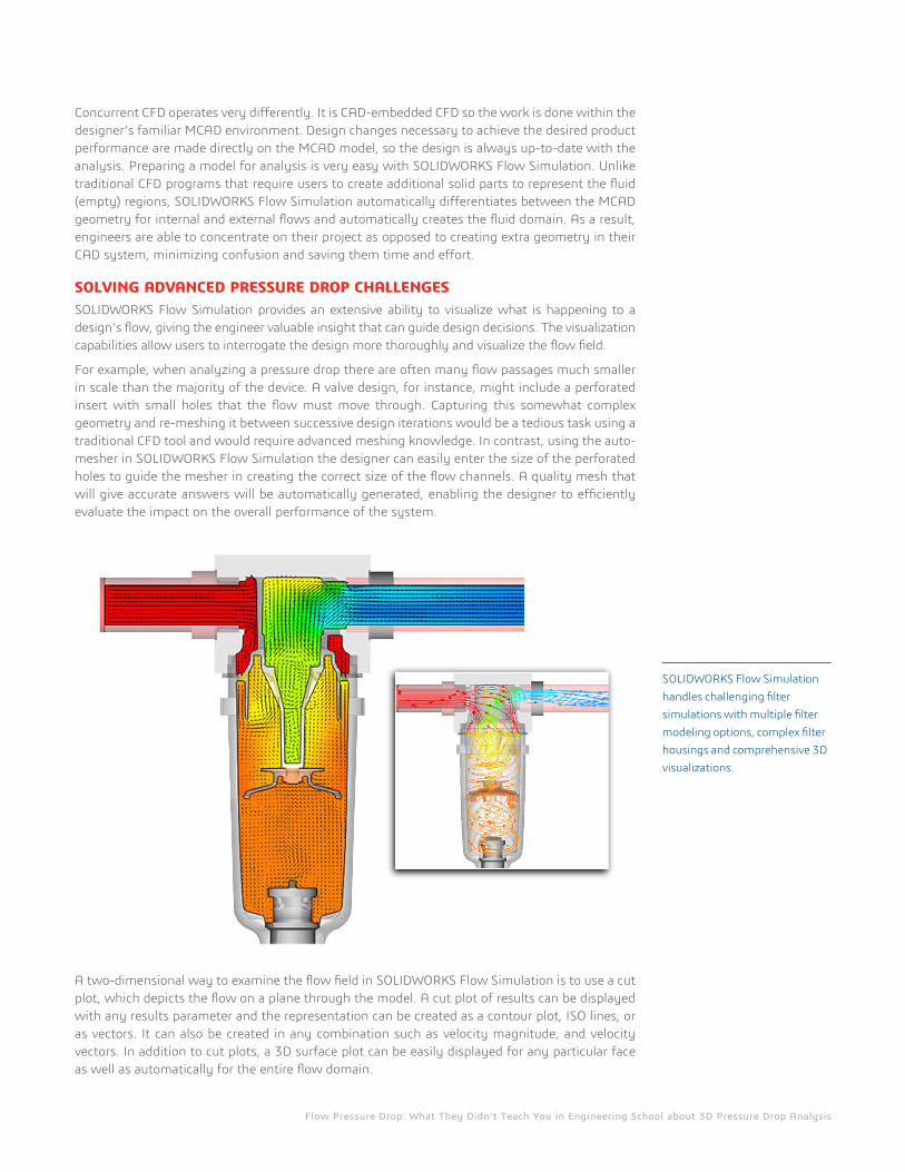
For example, when analyzing a pressure drop there are often many flow passages much smaller in scale than the majority of the device. A valve design, for instance, might include a perforated insert with small holes that the flow must move through. Capturing this somewhat complex geometry and re-meshing it between successive design iterations would be a tedious task using a traditional CFD tool and would require advanced meshing knowledge. In contrast, using the auto-mesher in SOLIDWORKS Flow Simulation the designer can easily enter the size of the perforated holes to guide the mesher in creating the correct size of the flow channels. A quality mesh that will give accurate answers will be automatically generated, enabling the designer to efficiently evaluate the impact on the overall performance of the system.
A two-dimensional way to examine the flow field in SOLIDWORKS Flow Simulation is to use a cut plot, which depicts the flow on a plane through the model. A cut plot of results can be displayed with any results parameter and the representation can be created as a contour plot, ISO lines, or as vectors. It can also be created in any combination such as velocity magnitude, and velocity vectors. In addition to cut plots, a 3D surface plot can be easily displayed for any particular face as well as automatically for the entire flow domain.
SOLIDWORKS Flow Simulation handles challenging filter simulations with multiple filter modeling options, complex filter housings and comprehensive 3D visualizations.
Flow Pressure Drop: What They Didn’t Teach You in Engineering School about 3D Pressure Drop Analysis
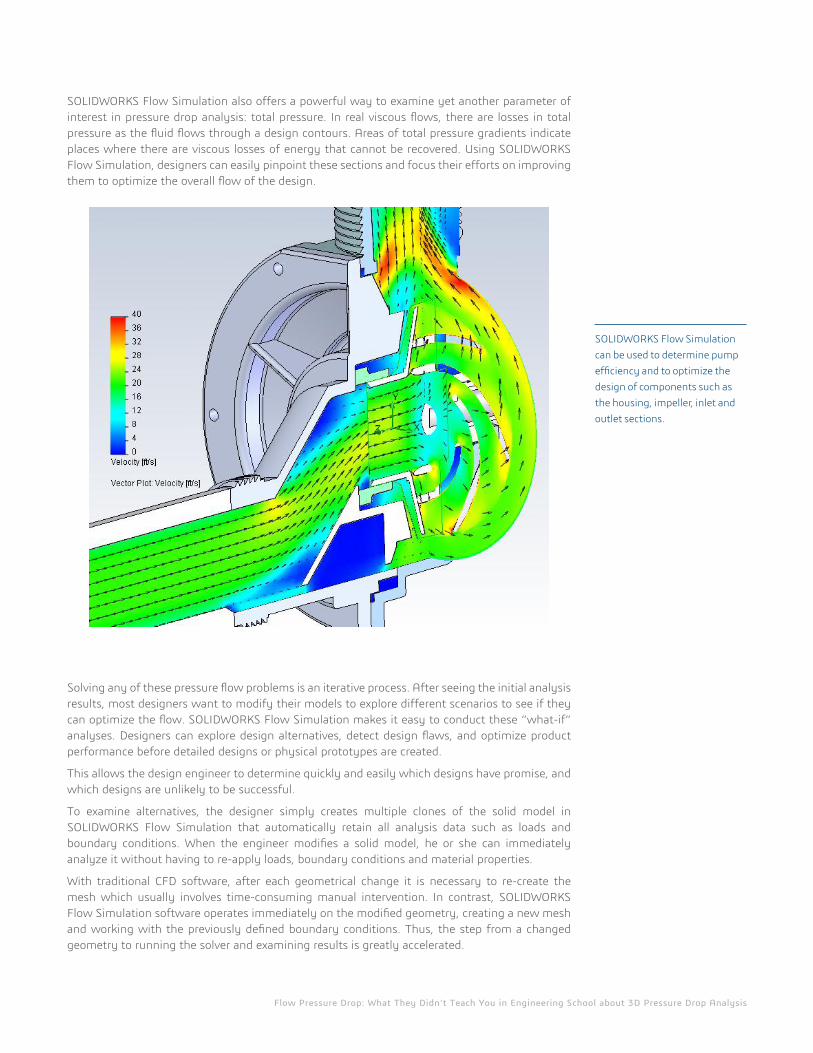
SOLIDWORKS Flow Simulation also offers a powerful way to examine yet another parameter of interest in pressure drop analysis: total pressure. In real viscous flows, there are losses in total pressure as the fluid flows through a design contours. Areas of total pressure gradients indicate places where there are viscous losses of energy that cannot be recovered. Using SOLIDWORKS Flow Simulation, designers can easily pinpoint these sections and focus their efforts on improving them to optimize the overall flow of the design.
Solving any of these pressure flow problems is an iterative process. After seeing the initial analysis results, most designers want to modify their models to explore different scenarios to see if they can optimize the flow. SOLIDWORKS Flow Simulation makes it easy to conduct these “what-if” analyses. Designers can explore design alternatives, detect design flaws, and optimize product performance before detailed designs or physical prototypes are created.
This allows the design engineer to determine quickly and easily which designs have promise, and which designs are unlikely to be successful.
To examine alternatives, the designer simply creates multiple clones of the solid model in SOLIDWORKS Flow Simulation that automatically retain all analysis data such as loads and boundary conditions. When the engineer modifies a solid model, he or she can immediately analyze it without having to re-apply loads, boundary conditions and material properties.
With traditional CFD software, after each geometrical change it is necessary to re-create the mesh which usually involves time-consuming manual intervention. In contrast, SOLIDWORKS Flow Simulation software operates immediately on the modified geometry, creating a new mesh and working with the previously defined boundary conditions. Thus, the step from a changed geometry to running the solver and examining results is greatly accelerated.
SOLIDWORKS Flow Simulation can be used to determine pump efficiency and to optimize the design of components such as the housing, impeller, inlet and outlet sections.
Flow Pressure Drop: What They Didn’t Teach You in Engineering School about 3D Pressure Drop Analysis
The software also aids in parametric study—for example, running studies with various wall thickness scenarios to determine the optimal thickness. In these ways, SOLIDWORKS Flow Simulation accelerates the iterative design process, allowing engineers to quickly and easily incorporate knowledge gained in an analysis into an improved design.
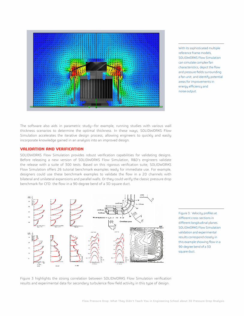
VALIDATION AND VERIFICATIONSOLIDWORKS Flow Simulation provides robust verification capabilities for validating designs. Before releasing a new version of SOLIDWORKS Flow Simulation, R&D‘s engineers validate the release with a suite of 300 tests. Based on this rigorous verification suite, SOLIDWORKS Flow Simulation offers 26 tutorial benchmark examples ready for immediate use. For example, designers could use these benchmark examples to validate the flow in a 2D channels with bilateral and unilateral expansions and parallel walls. Or they could verify the classic pressure drop benchmark for CFD: the flow in a 90-degree bend of a 3D square duct.
Figure 3 highlights the strong correlation between SOLIDWORKS Flow Simulation verification results and experimental data for secondary turbulence flow field activity in this type of design.
With its sophisticated multiple reference frame models, SOLIDWORKS Flow Simulation can simulate complex fan characteristics, depict the flow and pressure fields surrounding a fan unit, and identify potential areas for improvements in energy efficiency and noise output.
Figure 3: Velocity profiles at different cross-sections in different longitudinal planes. SOLIDWORKS Flow Simulation validation and experimental results correspond closely in this example showing flow in a 90-degree bend of a 3D square duct.
Flow Pressure Drop: What They Didn’t Teach You in Engineering School about 3D Pressure Drop Analysis
COMMUNICATIONOnce the results are available, the product engineer needs to report his/her findings to others. SOLIDWORKS Flow Simulation is fully integrated with Microsoft® Word® and Excel®, allowing engineers to create report documents and collect important data in graphical form from any SOLIDWORKS Flow Simulation project. In addition it automatically creates Excel spreadsheets summarizing the outputs of an analysis.
By using SOLIDWORKS Flow Simulation the product engineer can create a customized report, including the boundary conditions, the material properties, the mesh definition and the results plots, that is automatically saved in a word document. This report is a valuable project asset and is often archived by your data management system.
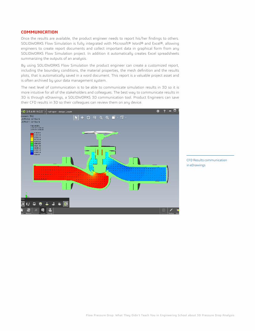
The next level of communication is to be able to communicate simulation results in 3D so it is more intuitive for all of the stakeholders and colleagues. The best way to communicate results in 3D is through eDrawings, a SOLIDWORKS 3D communication tool. Product Engineers can save their CFD results in 3D so their colleagues can review them on any device.
CFD Results communication in eDrawings
Flow Pressure Drop: What They Didn’t Teach You in Engineering School about 3D Pressure Drop Analysis
REAL WORLD DESIGNERS With SOLIDWORKS Flow Simulation, designers can focus on improving product performance and functionality without requiring them to become full-time fluid dynamics specialists. The following real-world examples, accumulated over the past few years, demonstrate the effectiveness of SOLIDWORKS Flow Simulation in helping designers meet tight deadlines, achieve higher quality results and/or minimize costs.
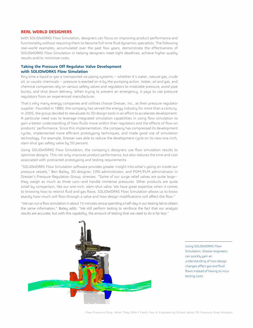
Taking the Pressure Off Regulator Valve Development with SOLIDWORKS Flow SimulationAny time a liquid or gas is transported via piping systems -- whether it’s water, natural gas, crude oil, or caustic chemicals -- pressure is exerted on it by the pumping action. Water, oil and gas, and chemical companies rely on various safety valves and regulators to modulate pressure, avoid pipe bursts, and shut down delivery. When trying to prevent an emergency, it pays to use pressure regulators from an experienced manufacturer.
That’s why many energy companies and utilities choose Dresser, Inc., as their pressure regulator supplier. Founded in 1880, the company has served the energy industry for more than a century. In 2005, the group decided to reevaluate its 3D design tools in an effort to accelerate development. A particular need was to leverage integrated simulation capabilities in using flow simulation to gain a better understanding of how fluids move within their regulators and the effects of flow on products’ performance. Since this implementation, the company has compressed its development cycles, implemented more efficient prototyping techniques, and made good use of simulation technology. For example, Dresser was able to reduce the development cycle on its new one-inch, slam-shut gas safety valve by 50 percent.
Using SOLIDWORKS Flow Simulation, the company’s designers use flow simulation results to optimize designs. This not only improves product performance, but also reduces the time and cost associated with protracted prototyping and testing requirements.
“SOLIDWORKS Flow Simulation software provides greater insight into what’s going on inside our pressure vessels,” Ben Bailey, 3D designer, CAD administrator, and PDM/PLM administrator in Dresser’s Pressure Regulation Group, stresses. “Some of our surge relief valves are quite large—they weigh as much as three cars—and handle immense pressures. Other products are quite small by comparison, like our one-inch, slam-shut valve. We have great expertise when it comes to knowing how to restrict fluid and gas flows. SOLIDWORKS Flow Simulation allows us to know exactly how much will flow through a valve and how design modifications will affect the flow.”
“We can run a flow simulation in about 15 minutes versus spending a half-day in our testing lab to obtain the same information,” Bailey adds. “We still perform testing to reinforce the fact that our analysis results are accurate; but with this capability, the amount of testing that we need to do is far less.”
Using SOLIDWORKS Flow Simulation, Dresser engineers can quickly gain an understanding of how design changes affect gas and fluid flows instead of having to incur testing costs
Flow Pressure Drop: What They Didn’t Teach You in Engineering School about 3D Pressure Drop Analysis
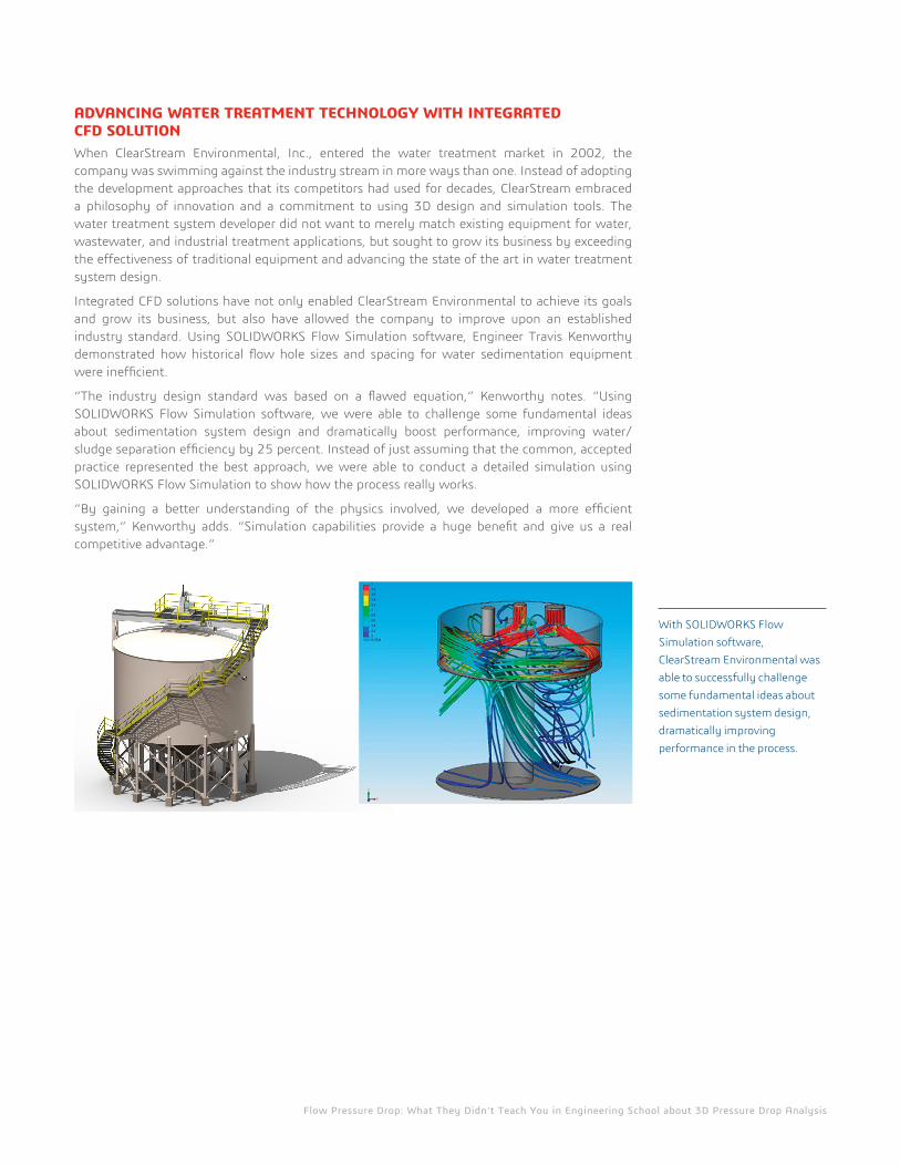
ADVANCING WATER TREATMENT TECHNOLOGY WITH INTEGRATED CFD SOLUTIONWhen ClearStream Environmental, Inc., entered the water treatment market in 2002, the company was swimming against the industry stream in more ways than one. Instead of adopting the development approaches that its competitors had used for decades, ClearStream embraced a philosophy of innovation and a commitment to using 3D design and simulation tools. The water treatment system developer did not want to merely match existing equipment for water, wastewater, and industrial treatment applications, but sought to grow its business by exceeding the effectiveness of traditional equipment and advancing the state of the art in water treatment system design.
Integrated CFD solutions have not only enabled ClearStream Environmental to achieve its goals and grow its business, but also have allowed the company to improve upon an established industry standard. Using SOLIDWORKS Flow Simulation software, Engineer Travis Kenworthy demonstrated how historical flow hole sizes and spacing for water sedimentation equipment were inefficient.
“The industry design standard was based on a flawed equation,” Kenworthy notes. “Using SOLIDWORKS Flow Simulation software, we were able to challenge some fundamental ideas about sedimentation system design and dramatically boost performance, improving water/sludge separation efficiency by 25 percent. Instead of just assuming that the common, accepted practice represented the best approach, we were able to conduct a detailed simulation using SOLIDWORKS Flow Simulation to show how the process really works.
“By gaining a better understanding of the physics involved, we developed a more efficient system,” Kenworthy adds. “Simulation capabilities provide a huge benefit and give us a real competitive advantage.”
With SOLIDWORKS Flow Simulation software, ClearStream Environmental was able to successfully challenge some fundamental ideas about sedimentation system design, dramatically improving performance in the process.
Our 3DEXPERIENCE Platform powers our brand applications, serving 12 industries, and provides a rich portfolio of industry solution experiences. Dassault Systèmes, the 3DEXPERIENCE Company, provides business and people with virtual universes to imagine sustainable innovations. Its world-leading solutions transform the way products are designed, produced, and supported. Dassault Systèmes’ collaborative solutions foster social innovation, expanding possibilities for the virtual world to improve the real world. The group brings value to over 170,000 customers of all sizes in all industries in more than 140 countries. For more information, visit www.3ds.com.
©20
14 D
assa
ult S
ystè
mes
. All
righ
ts re
serv
ed. 3
DEX
PER
IEN
CE, t
he C
ompa
ss ic
on a
nd th
e 3D
S lo
go, C
ATI
A, S
OLI
DW
OR
KS, E
NO
VIA
, DEL
MIA
, SIM
ULI
A, G
EOVI
A, E
XALE
AD
, 3D
VIA
, BIO
VIA
, NET
VIB
ES, 3
DSW
YM, a
nd 3
DEX
CITE
are
com
mer
cial
trad
emar
ks
or re
gist
ered
trad
emar
ks o
f Das
saul
t Sys
tèm
es o
r its
sub
sidi
arie
s in
the
U.S
. and
/or o
ther
cou
ntri
es. A
ll ot
her t
rade
mar
ks a
re o
wne
d by
thei
r res
pect
ive
owne
rs. U
se o
f any
Das
saul
t Sys
tèm
es o
r its
sub
sidi
arie
s tr
adem
arks
is s
ubje
ct to
thei
r exp
ress
wri
tten
app
rova
l.
Corporate HeadquartersDassault Systèmes 10, rue Marcel Dassault CS 40501 78946 Vélizy-Villacoublay Cedex France
AmericasDassault Systèmes SolidWorks Corporation 175 Wyman Street Waltham, MA 02451 USA Phone: 1 800 693 9000 Outside the US: +1 781 810 5011 Email: [email protected]
Asia-PacificDassault Systèmes K.K.ThnkPark Tower2-1-1 Osaki, Shinagawa-ku,Tokyo 141-6020Japan
CFD FOR ALL PRODUCT ENGINEERSFor systems where fluid is flowing inside of a product, pressure drop is a critical characteristic to understand. Unfortunately, the traditional technique used to measure pressure drop is through experience or estimation with expensive and time consuming physical prototype testing.
SOLIDWORKS Flow Simulation moves away from tradition by taking a concurrent engineering approach. Concurrent engineering gives product engineers the power to accurately analyze complex systems, as well as component pressures, to ensure reliability before products are finalized. For example, while using this approach, pressure-related parameters can then be explored using ‘what-if’ scenarios over a wide range of flow regimes.
With a 20 year history, SOLIDWORKS Flow Simulation gives every product engineer the ability to evaluate how their designs will work in the real world; and analysis as you design allows you to make important design decisions with confidence.